Guidelines for Application of Ballast Water Treatment ... · PDF fileGuideline for Application...
291
Guidelines for Application of Ballast Water Treatment Systems in Ships 2010 Machinery Team Korean Register of Shipping
Transcript of Guidelines for Application of Ballast Water Treatment ... · PDF fileGuideline for Application...

Guidelines for Application of Ballast
Water Treatment Systems in Ships
2010
Machinery Team
Korean Register of Shipping

Guideline for Application of BWTS in Ships Machinery Team1
Preamble
The world's trade and traffic volume have been rapidly expanded over the last few decades
resulting in environmental damages caused by invasive species in ship's ballast water. The effects
in many areas have been reported that our ecosystem is being disturbed at an alarming rate. Since
the volume of sea-born trade continues to increase, the rate of bio-invasions is also expected to
continuously increase.
In 1988, Canada and Australia first reported on invasive marine species in ballast waters. In
response, IMO adopted, at its assembly in 1993, Res. A. 774(18 ) “Guidelines for preventing the
introduction of unwanted aquatic organism and pathogens from ship's ballast water and sediments
discharges”. After more than 14 years of complex negotiations between IMO Member States,
the International Convention for the Control and Management of Ships' Ballast Water and
sedimentss (BWM Convention) was adopted at the Diplomatic Conference held at IMO
Headquarters in London on 13 February 2004. This convention will enter into force 12 month
after the date on which not less than 30 states, the combined merchant fleets of which
constitute not less than 35% of the gross tonnage of the world's merchant shipping.
There have been many questions regarding the installation requirements of Ballast Water
Treatment System (BWTS) raised by ship owners and shipyards as the effective date of BWM
convention(2004) is approaching. In response, Korean Register of Shipping outlined reference
information for the selection/installation of BWTS by vessel type.
This interim guidelines is based on the discussions carried out so far and revised edition will be
issued should there be any additional requirements or unified representation set out by IMO or
IACS.
We hope this guidelines would help ship owners, shipyard and field surveyors and encourage
readers to provide advise and guidance for further improvement.
Contact : Kim, Jung-hoon / Principle Surveyor (042-869-9454, [email protected]) Jang, Jae-shik / Senior Surveyor (042-869-9456, [email protected]) Lee, Sang-su / Deputy Senior Surveyor (042-869-9451, [email protected]) Kim, Jun-tae / Deputy Senior Surveyor (042-869-9457, [email protected]) Kong, Young-gyu / Surveyor (042-869-9481, [email protected])
Chief Editor : Oh, Joo-won / General Manager of Machinery Team(042-869-9440, [email protected])
- In order to avoid any potential damage to Korea Register, dissemination, distribution or copying of this document is prohibited without prior permission from the publishing division.
2
Table of Contents
Part I Introduction to Ballast Water Management Convention
1. Outline of Ballast Water Management Convention 2004 ········································· 42. MEPC Meetings ··················································································································· 8
Part II Application of Ballast Water Treatment System
1. Outline of Ballast Water Treatment Systems ···························································· 122. General Aspect of Ballast Water Treatment Systems ············································ 123. Type Approval of Ballast Water Treatment Systems ·············································· 17
Part III Technologies for Ballast Water Treatment Systems
1. Ballast Water Treatment Technologies ········································································ 232. Characteristics of Ballast Water Treatment Systems by Manufacturers ············· 28
Part IV Application of Ballast Water Treatment Systems
1. Ships other than Tankers ······························································································· 572. Oil Tankers ························································································································· 713. Chemical Tankers ············································································································· 904. Gas Carriers ····················································································································· 110
Part V Ballast Water Sampling
1. General ······························································································································ 1272. Requirements for Ballast Water Sampling ······························································· 1273. Assessment of Sampling Pipe Installation Using CFD ········································· 129
Part VI Approval of Ballast Water Treatment Systems
1. Requirements for Ballast Water Treatment Systems ············································ 1312. Drawing Approval and On-board Inspection ···························································· 1363. Application of Local Regulations ··············································································· 139

Guideline for Application of BWTS in Ships Machinery Team3
Appendix
A. Hazardous Areas and Requirements for Electrical Installation in
Each Ship Type
B. Requirements for Ballast Water Treatment in California
C. Requirements for Ballast Water Treatment in New York
D. Means to Verify Ballast Water Treatment Systems for Ships
Entering Australian Ports
E. Questionnaires [BWTS manufacturers]
Part I Introduction to Ballast Water Management Convention
Guideline for Application of BWTS in Ships Machinery Team4
Part I Introduction to Ballast Water Management Convention
Outline of Ballast Water Management Convention 2004
The Ballast Water Treatment Convention 2004 (hereinafter the "BWM Conention") consists of a Preamble, 24 Articles and an Annex which is made up of 24 regulations and 2 appendices. (Refer to Table. I-1-A BWM Convention).
There are many complicated technical requirements and procedures to meet this convention where different measures may be taken by different countries resulting in increased complication. Hence, for the uniform implementation of the BWM convention, IMO set out 14 guidelines (Refer to Table. I-1-B and Fig. I-1-A).
Of the 14 guidelines, the "Guidelines for Ballast Water Sampling (G2)", "Guidelines for Approval of Ballast Water Management Systems (G8)", "Procedure for Approval of Ballast water Management Systems that make use of Active Substances (G9)", "Guidelines for Approval and Oversight of prototype Ballast Water Treatment Technology programmes (G10)", "Guidelines for Risk Assessment under Regulation (G7)", "Guidelines on Designation of Areas for Balalst Water Exchange (G14)" and "Guidelines for Additional Measures regarding Ballast Water Management including Emergency Situation (G13)" are intended to governments, while the "Guidelines for Ballast Water Management Equivalent Compliance (G3)", "Guidelines for Ballast Water Management and Development of Ballast Water Management Plans (G4)", "Guidelines for Ballast Water Exchange (G6)", "Guidelines for Ballast Water Exchange Design and Construction Standards (G11)" and "Guidelines on Design and Construction to Facilitate sediments Control on Ships (G12)" are intended to ship owners and shipyards.

International Convention for the Control and Management of Ship's Ballast Water and sedimentss
Preamble
Article
Article 1 Definition Article 12 Undye Delay to Ships
Article 2 General obligations Article 13 Technical Assistance, Co-operation and Regional Co-operation
Article 3 Application Article 14 Communication of Information
Article 4
Control of the Transfer of Harmful Aquatic Organism and Pathogens Through Ship's Ballast Water sedimentss
Article 15 Dispute Settlement
Article 5 sedimentss Reception Facilities Article 16 Relationship to International Law
and other Agreements
Article 6 Scientific and Technical Research and Monitoring Article 17 Signature, Ratification, Acceptance,
Approval and Accession
Article 7 Survey and Certification Article 18 Entry into ForceArticle 8 Violation Article 19 AmendmentsArticle 9 Inspection of Ships Article 20 Denunciation
Article 10 Detection of Violation and Control of Ships Article 21 Depositary
Article 11 Notification of Control Actions Article 22 Language
Part I Introduction to Ballast Water Management Convention
Guideline for Application of BWTS in Ships Machinery Team5
Annex
Section A - General Provision Reg. A-1 DefinitionsReg. A-2 General ApplicabilityReg. A-3 ExeptionsReg. A-4 ExemptionsReg. A-5 Equivalent Compliance
Section B - Management and Control Requirements for Ships Reg. B-1 Ballast Water Management Plan
Reg. B-2 Ballast Water Record Book
Reg. B-3 Ballast Water Management for Ships
Reg. B-4 Ballast Water ExchangeReg. B-5 sediments Management for ShipsReg. B-6 Duties of Officers and Crew
Section C - Special Requirements in Certain Areas Reg. C-1 Additional Measures
Reg. C-2Warning concerning Ballast Water Uptake in Certain Areas and Related Flag Sate Measures
Reg. C-3 Communication of InformationSection D - Standard for Ballast Water Management Reg. D-1 Ballast Water Exchange Standard
Reg. D-2 Ballast Water Performance Standard
Reg. D-3 Approval Requirement for Ballast Water Management System
Reg. D-4 Prototype Ballast Water Treatment Technologies
Reg. D-5 Review of Standards by the
Table. I-1-A Ballast Water Management Convention
Part I Introduction to Ballast Water Management Convention
Guideline for Application of BWTS in Ships Machinery Team6
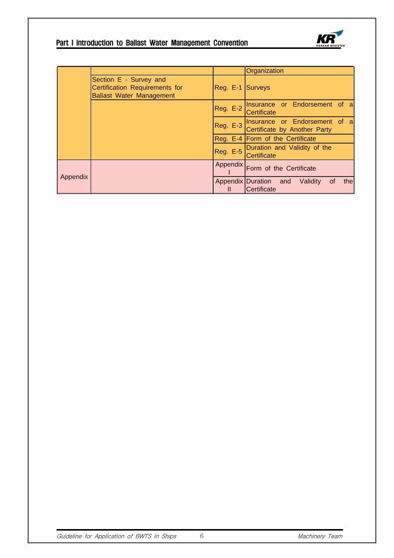
OrganizationSection E - Survey and Certification Requirements for Ballast Water Management
Reg. E-1 Surveys
Reg. E-2 Insurance or Endorsement of a Certificate
Reg. E-3 Insurance or Endorsement of a Certificate by Another Party
Reg. E-4 Form of the Certificate
Reg. E-5 Duration and Validity of the Certificate
Appendix
Appendix I Form of the Certificate
Appendix II
Duration and Validity of the Certificate

Part I Introduction to Ballast Water Management Convention
Guideline for Application of BWTS in Ships Machinery Team7
Table. I-1-B Ballast Water Management Guidelines
No Ballast Water Management Guidelines MEPC Resolution
G1 Guidelines for sediments Reception Facilities Res.MEPC.152(55)
G2 Guidelines for Ballast Water Sampling Res.MEPC.173(58)
G3 Guidelines for Ballast Water Management Equivalent Compliance Res.MEPC.123(53)
G4 Guidelines for Ballast Water Management and Development of Ballast Water Management Plans Res.MEPC.127(53)
G5 Guidelines for Ballast Water Reception Facilities Res.MEPC.153(55)
G6 Guidelines for Ballast Water Exchange Res.MEPC.124(53)
G7 Guidelines for Risk Assessment under Regulation A-4 Res.MEPC.162(56)
G8 Guidelines for Approval of Ballast Water Management Systems Res.MEPC.174(58)
G9 Guidelines for Approval of Ballast Water Management Systems that use of Active Substances Res.MEPC.169(57)
G10 Guidelines for Approval and Oversight of Prototype Ballast Water Treatment Technology Programs Res.MEPC.140(54)
G11 Guidelines for Ballast Exchange Design and Construction Standards Res.MEPC.149(55)
G12 Guidelines on Design and Construction to Facilitate sediments Control on Ships Res.MEPC.150(55)
G13 Guidelines for Additional Measures regarding Ballast Water Management including Emergency Situation Res.MEPC.161(56)
G14 Guidelines on Designation of Areas for Ballast Water Exchange Res.MEPC.151(55)

Part I Introduction to Ballast Water Management Convention
Guideline for Application of BWTS in Ships Machinery Team8
Fig. I-1-A Ballast Water Management Convention Guidelines
MEPC Meetings
The guidelines for application of BWM Convention have been discussed and selected at MEPC. In this chapter, the details of MEPC meetings as of 2010.12 will be briefly introduced.
2.1 MEPC 59(2009. 7) Meeting
2.1.1 Basic/final Approval Status of Ballast Water Systems that Make Use of Active Substances. 1) Approval status as of MEPC 58 is listed in BWM.2/Circ.16(2008.10.17) and further
Basic/Final Approval for the sediments of active substances produced during ballast water treatment will be issued as BWM.2/Circ.**.
Country Manufacturer Product Approval Related Document Status
Korea HHI EcoBallast Basic Approval MEPC59/2/4 Approved
Germany Aquaworx Aqua TriComb Basic Approval MEPC59/2/8 Approved
China COSCO Blue Ocean Shield Basic Approval MEPC59/2/2 Approved
Korea NK NK-03 BlueBallast Final Approval MEPC59/2/3 Approved
Germany RWO CleanBallast Final Approval MEPC59/2 Approved
Japan Hitachi ClearBallast Final Approval MEPC59/2/5 Approved
Netherland Greenship Greenship Sedinox Final Approval MEPC59/2/6 Approved
Note : Techross (Korea) was approved at MEPC 59.
2.1.2 Using Portable Water as Ship's Ballast Water 1) The committee at this session acknowledged that chemical contained in portable
water may potentially be discharged and agreed that any water used as ballast should comply with the Ballast Water Convention. This matter will be further discussed at BLG after the finalization of “Procedure for assessing other methods of ballast water management".
2.1.3 Possible Further Extension of the Entry Into Force of D2 (Ballast Water Treatment System Onboard) for New Ships Built in 2010 and with a Ballast Water Capacity Less than 5,000m3
1) The committee noted that postponing the date stipulated in regulation B-3.3 would

Part I Introduction to Ballast Water Management Convention
Guideline for Application of BWTS in Ships Machinery Team9
not be beneficial to the implementation process and would not stimulate the installation of new ballast water technologies on board ships, hence concluded that no change to Assembly A.1005(25) was needed for those constructed in 2010.
2.2 MEPC 60(2010. 3) Meeting
2.2.1 GESAMP-BWWG provided basic approval for the following active substances and encouraged manufacturers to apply for final approval.
Country Manufacturer Product Approval Related Document Status
Korea Panasia GloEn-Patrol Final Approval MEPC59/2/7 Approved
Germany Ecochlor Ecochlor Final Approval MEPC59/2/9 Rejected
Germany Siemens SiCURE Basic Approval MEPC59/2/11 Approved
South Africa
Resource Ballast Tech. Resource Final
Approval MEPC59/2/10 Approved
Denmark ATLAS-DANMARK ATLAS-DANMARK Basic Approval MEPC60/2 Rejected
Japan Toagosei JEF Final Approval MEPC60/2/2 Approved
China Sunrui CFCC Sunrui Basic Approval MEPC60/2/3 Approved
Denmark DESMI Ocean Guard Basic Approval MEPC60/2/4 Approved
Korea 21st Century Shipbuilding Co.Ltd Blue Ocean Guard Basic
Approval MEPC60/2/5 Approved
Korea Hyundai HeavyIndustries Co. Ltd. HiBallast Basic
Approval MEPC60/2/6 Approved
Korea Kwang San Co., Ltd. En-Ballast Basic Approval MEPC60/2/7 Approved
Norway Qingdao Headway OceanGuard Basic Approval MEPC60/2/8 Approved
Germany Severn TrentDeNora BalPure Basic
Approval MEPC60/2/9 Approved
Korea Hyundai HeavyIndustries Co. Ltd. EcoBallast1) Final
Approval MEPC60/2/1 Approved
1) : Not reviewed by the GESAMP-BWWG, however, it had been deemed to have met all the requirements
for final approval at MEPC 59 and therefore was advised to apply for final approval at MEPC 60. Accordingly, this system received a final approval at this session.
2.2.2 Follow-up Measures to IMO Res.A.1005(25)1) It is deemed that there are sufficient numbers of type approved ballast water
treatment systems available in the market, and therefore at MEPC 59, it was agreed to provide no further extension other than [IMO Res.A.1005(25) : Delay of entry into force for vessels constructed in 2009] which was adopted at the 25th IMO assembly

Part I Introduction to Ballast Water Management Convention
Guideline for Application of BWTS in Ships Machinery Team10
(2007.11). The committee encouraged its member states for the prompt ratification of the BWM convention and installation of the ballast water treatment system before entry into force of the convention
2.3 MEPC 61(2010. 9) Meeting
2.3.1 The GESAMP-BWWG recommended basic/final approval for the following treatment systems that make use of active substances.
Country Manufacturer Product Approval Related Document Status
Korea Techone Eco Purimar Basic Approval MEPC61/2 Approved
Korea Aqua ENG Aquastar Basic Approval MEPC60/2/1 Approved
Japan Kuraray Kuraray Basic Approval MEPC60/2/6 Approved
Japan Mitsui Heavy Ind. FineBallast1)
Korea 21st Century Shipbuilding Co.Ltd ARA Ballast Final
Approval MEPC61/2/5 Approved
Norway Qingdao headway OceanGuard Final Approval MEPC60/2/2 Approved
Germany Severn TrentDeNora BalPure Final
Approval MEPC61/2/9 Approved
Germany Eka Chem Ecochlor Final Approval MEPC61/2/8 Approved
Japan Mitsui Heavy Ind. SP-Hybrid Final Approval MEPC61/2/2 Approved
China Sunrui CFCC BalClor Final Approval MEPC61/2/4 Approved
1) : No active substances are used. Hence, recommended to apply for government type approval in accordance with G8.
2.3.2 The Current Status of BWM Convention (As of November 2010)1) No. of contracting states : 27 countries2) Sum of tonnage : 25.32%3) This convention will enter into force 12 month after the date on which not less than
30 states, the combined merchant fleets of which constitutes not less than 35% of the gross tonnage of the world's merchant shipping.

Part II Application of Ballast Water Treatment Systems
Guideline for Application of BWTS in Ships Machinery Team11
Part II Application of Ballast Water Treatment Systems
Outline of Ballast Water Treatment Systems
In prior to the development and commercialization of BWTS, active substances used in the treatment process should be approved by IMO for its potential impact to the marine environment. Active substance means a substance or organism, including a virus or a fungus that has a general or specific action on or against harmful Aquatic Organisms and Pathogens. The approval steps are divided into basic approval and final approval, and each step should be approved by MEPC.
A BWTS received basic approval and final approval by IMO is then required to grant type approval by each country for its organism extinction ability, operational performance and application on board ships. In order to receive the type approval, a land-based test demonstrating that the BWTS meets the requirements of Guidelines for Approval of Ballast Water Management Systems (G8) and the standard as set out in Regulation D-2 of the Convention should be carried out at a equipment factory where a laboratory pilot plant including a moored test barge or test ship. Also, in order to assess whether the BWTS meets the standards of Regulation D-2, an on-board test should be carried out at the BWTS's maximum capacity.
And, in order to verify the performance of BWTS under ship's operating condition, the test should be of carried out under following conditions ; vibration, temperature, moisture, green sea, ship's trim, and electrical load change. And the tests should able to evaluate the liability of the electrical equipment.
General Aspect of Ballast Water Treatment Systems
2.1 General
2.1.1 Definitions1) "Ballast Water" means water with its suspended matter taken on board a ship to
control trim, list, draught, stability or stress of the ship.2) "Ballast Water Treatment" means mechanical, physical, chemical, and biological
processes, either singularly or in combination to remove, render harmless, or avoid the uptake or discharge of Harmful Aquatic Organisms and Pathogens within Ballast Water sediments.
3) "Gross Tonnage" means the gross tonnage calculated in accordance with the tonnage measurement regulations contained in Annex 1 to the International Convention on Tonnage Measurement of Ships, 1969 or any successor Convention.
4) "Ship" means a vessel of any type whatsoever operating in the aquatic environment

Part II Application of Ballast Water Treatment Systems
Guideline for Application of BWTS in Ships Machinery Team12
and includes submersibles, floating craft, floating platforms, FSUs and FPSOs. 5) "sedimentss" means matter settled out of Ballast Wataer within a ship.6) "Ballast Water Capacity" means the total volumetric capacity of any tanks, spaces
or compartments on a ship used for carrying, loading or discharging Ballast Water, including any multi-use tank, space or compartment designed to allow carriage of Ballast Water.
7) "Active substance" means a substance or organism, including a virus or a fungus that has a general or specific action on or against Harmful Aquatic Organisms and Pathogens.
2.1.2 Definition of Constructed and Major Constructed1) "Constructed" in respect of a ship means a stage of construction where :
a. the keel is laid; or b. construction identifiable with the specific ship begins c. assembly of the ship has commenced comprising at least 50 tonnes or 1 percent of
the estimated mass of all structural material, whichever is less; or d. the ship undergoes a major conversion
2) "Major conversion" means a conversion of a ship a. which change its ballast water carrying capacity by 15 percent or greater, or b. which changes the ship type, or c. which, in the opinion of the Administration, is projected to prolong its life by ten years
or more, or d. which results in modifications to its ballast water system other than component
replacement-in-kind. Conversion of a ship to meet the provisions of regulation D-1 should not be deemed to constitute a major conversion for the purpose of this Annex.
2.2 Application
2.2.1 Extent of Application1) Applies to all ships designed to carry ballast water (submersible vessel, floating
vessel, FSUs, and FPSOs
2.2.2 Ships Subject to Survey1) Except Floating Platform, FSUs or FPSOs, all ships over GT 400 ton are required to
furnish a certificate of survey stipulated by the convention on board ships.
2.2.3 Exceptions 1) Ships not designed or constructed to carry Ballast Water or ships having permanent
ballast water in sealed tanks on ships, that is not subject to discharge 2) Any warship, naval auxiliary or other ship owned or operated by a state and used,
for the time being, only on government non-commercial service.3) Ships not designed or constructed to carry Ballast Water.
Part II Application of Ballast Water Treatment Systems
Guideline for Application of BWTS in Ships Machinery Team13
D2-≥ 2012
D2D1 or D2≥ 5000
2009 ~ 2011
D2 < 5000 ≥ 2009
Ships whose keel is laid after 2009
D2D1 or D2> 5000 < 2009
D2D1 or D21500 ~ 5000 < 2009
D2D1 or D2< 1500 < 2009
Ships whose keel is laid before 2009
201720162015201420132012201120102009BW Tank(m3)Keel Laying기준
D2-≥ 2012
D2D1 or D2≥ 5000
2009 ~ 2011
D2 < 5000 ≥ 2009
Ships whose keel is laid after 2009
D2D1 or D2> 5000 < 2009
D2D1 or D21500 ~ 5000 < 2009
D2D1 or D2< 1500 < 2009
Ships whose keel is laid before 2009
201720162015201420132012201120102009BW Tank(m3)Keel Laying기준
2.2.4 Equivalent Compliance1) Equivalent compliance for pleasure craft used solely for recreation or competition or
craft used primarily for search and rescue, less than 50 meters in length overall, and with a maximum Ballast Water capacity of 8 cubic meters, should be determined by the Administration taking into account Guidelines developed by the Organization.
2.3 Entry into force of D-1 and D-2 Regulations
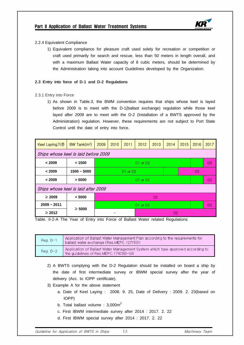
2.3.1 Entry into Force1) As shown in Table.3, the BWM convention requires that ships whose keel is layed
before 2009 is to meet with the D-1(ballast exchange) regulation while those keel layed after 2009 are to meet with the D-2 (Installation of a BWTS approved by the Administration) regulation. However, these requirements are not subject to Port State Control until the date of entry into force.
Table. II-2-A The Year of Entry into Force of Ballast Water related Regulations
2) A BWTS complying with the D-2 Regulation should be installed on board a ship by the date of first intermediate survey or IBWM special survey after the year of delivery (Acc. to IOPP certificate).
3) Example A for the above statement a. Date of Keel Laying : 2008. 9. 25, Date of Delivery : 2009. 2. 23(based on
IOPP) b. Total ballast volume : 3,000m3 c. First IBWM intermediate survey after 2014 : 2017. 2. 22 d. First IBWM special survey after 2014 : 2017. 2. 22

Part II Application of Ballast Water Treatment Systems
Guideline for Application of BWTS in Ships Machinery Team14
4) Example B for the above statement a. Date of Keel Laying : 1991.08.24, Date of Delivery : 1992. 5. 215(Acc. to IOPP) b. Total ballast volume : 6,000m3 c. First IBWM intermediate survey after 2014 : 2017. 5. 14 d. First IBWM special survey after 2020 : 2017. 5. 14
2.3.2 Standards for Ballast Exchange set out in Regulation D-1
1) Ships performing ballast water exchange should do so with an efficiency of at least 95% volumetric exchange of ballast water
2) For ships exchanging ballast water by the flow-through method, pumping through three times the volume of each ballast water tank should be considered to meet the standard described in paragraph 1. Pumping through less than three times the volume may be accepted provided that ships can demonstrate that at lease 95% volumetric exchange is met.
Table. II-2-B Standards for Ballast Exchange set out in Regulation D-1
2.3.3 Standards for Ballast Exchange set out in Regulation D-21) Less than 10 viable organism per cubic meter greater than or equal to 50
micrometers in minimum dimension2) Less than 10 viable organism per milliliter less than 50 micrometers in minimum
dimension and greater than or equal to 10 micrometers in minimum dimension3) Microbes indicator
a. Toxicogenic vibrio cholerae with less than 1 Colony Forming Unit (cfu) per 100 milliliters
b. Escherichia coli less than 250 cfu per 100 milliliters c. Intestinal Enterococci less than 100 cfu per 100 milliliters.

Part II Application of Ballast Water Treatment Systems
Guideline for Application of BWTS in Ships Machinery Team15
Table. II-2-C D-2 Standards for Ballast Exchange set out in Regulation D-2
2.3.4 Regarding requirements for California and New York, please refer to Appendix B and C.

Part II Application of Ballast Water Treatment Systems
Guideline for Application of BWTS in Ships Machinery Team16
Type Approval of Ballast Water Treatment Systems
3.1 General
Approval of Ballast Water Treatment Systems that make use of active substance is conducted at IMO according to "Procedure for Approval of Ballast Water Treatment Systems that Make Use of Active Substances (G9)". The purpose of the guideline (G9) is to determine the acceptability of active substances and preparations containing one or more active substances and their application in ballast water treatment systems concerning ship safety, human health and aquatic environment.
Basic approval means a pre-approval of the BWTS to comply with the requirements of the BWM Convention. At basic approval stage, it is to be verified that the application of BWTS has no harm to environment, human health, properties and resources.
Final approval means approval of ballast water treatment systems that make use of active substances or preparation to comply with the Convention. Type approval tests in accordance with "Guidelines for Approval of Ballast Water Management System (G8)" are regarded as a part of the final approval. Technical assessment for approval of active substances is conducted by BWWG (Ballast Water Working Group) which is under GESAMP (Group of Experts on Scientific Aspects of Marine Environmental Protection), where GESAMP-BWWG is a working group of GESAMP under MEPC. The working group is composed of experts from each field to review the application for the approval of ballast water treatment systems using active substance submitted by the Administration.
3.2 Procedure for IMO Type Approval
3.2.1 Approval Procedure for Ballast Water treatment Systems not using Active Substances. (Guidelines for Approval of Ballast Water Management System (G8))1) A BWTS that does not make use of an active substance should, without basic or
final approval by IMO, be approved by the Administration for fitting on board ships according to "Guidelines for Approval of Ballast Water Management System (G8").
2) A typical example of a BWTS that does not make use of active substances is a UV type.
3) Procedure for type approval according to "Guidelines for Approval of Ballast Water Management System (G8)" is shown in FIg. II-3-A. Also, registered organizations which are authorized to conduct the test on behalf of the Administration and test standards are shown in Table II-3-D.

Part II Application of Ballast Water Treatment Systems
Guideline for Application of BWTS in Ships Machinery Team17
Plan Approval : Design, Manufacturing,
Operation, Performance
Type approval Tests- Land-based Test (RO)- On-board Test (RO)- Environmental Test (RO)
- Feasibility Test (KR or KST)
Issue a Type
Approval Certificate
Inspection
On-board Ships
- KR (Korean Register of Shipping)
- KSSTA (Korea Ship Safety Technology Authority)
- KTL (Korea Testing Laboratory)
- KOMERI (Korea Marine Equipment Research Institute)
- SGS Tesco
- KORDI (Korea Ocean Research and Development Institute)
- KOMERI (Korea Marine Equipment Research Institute)
- Busan Techno Park
Registered Organizations Test StandardsTest Items
- Vibration Test
- Temperature Test
- Moisture Test
- IP Test
- Power Variation Test
- Incline Test
- EMC Test
Environmental Test
- Feasibility for ship's operation
- Performance of Alarm Device and Recording Equipment
- Control and Monitoring System
Feasibility Test
- Test cycle : more than 5 times per each cycle (PSU), minimum 2
cycles (total 10 times)
- Capacity of control tank and ballast tank should be greater than 200
m3
- Time of sampling : 3 times shortly before/after ballast water treatment
Land-based Test
- To comply with D-2 requirements after repeating ballast water
suction → storage → discharge process 3 times
- Test organism
- Sampling
On-board Test
Fig. II-3-A Type Approval Procedure According to Guidelines for Approval of Ballast Water Management System (G8)
Table. II-3-D Type Approval Procedure according to Guidelines for Approval of Ballast Water Management System (G8) [In Korea]

Part II Application of Ballast Water Treatment Systems
Guideline for Application of BWTS in Ships Machinery Team18
Application(Manufacturer)
Application (Member State)
Approval(IMO/MEPC)
Evaluation(IMO/GESAMP)
Approval(IMO/MEPC)
Circulation of Approval Result
AdditionalComments
- Submission of documents (laboratorial level)
- Assume discharge period
- Closure of Evaluation Result
- Evaluation and Analysis of Toxicity
- Report to the Administration
3.2.2 Procedure for Approval of Ballast Water Management Systems that Make Use of Active Substances (G9)1) A BWTS that make use of active substances should, according to "Procedure for
Approval of Ballast Water Management Systems that Make Use of Active Substances (G9)", acquire basic approval and final approval.
2) Procedures for basic approval and final approval are shown in Fig. II-3-B and Fig. II-3-C, respectively. The application form for basic approval should include information of the active substance.
3) Application for final approval should include a result of land-based test for confirmation that the residual toxicity of the discharge conforms to the evaluation undertaken for basic approval.
4) The application should be submitted under the name of applying member state and therefore all contents of the application should be guaranteed by the member state.
Fig. II-3-B Procedure for Basic Approval

Part II Application of Ballast Water Treatment Systems
Guideline for Application of BWTS in Ships Machinery Team19
Application(Manufacturer)
Land-based Test (Manufacturer + Member
State (Test Facility)]
Approval(IMO/MEPC)
Evaluation(IMO/GESAMP)
Approval(IMO/MEPC)
Circulation of Approval Result
Additional Comments
Application[Member State]
-Using Basic Approved Active Substances
-Comparing Toxicity of Discharged Ballast Water with the Figure Measured During Basic Approval
-Notification of Approval to the Administration and Circulation to Member States
Fig. II-3-C Procedure for Final Approval
5) A BWTS using active substances should conduct the following tests in addition to the tests required by "Guidelines for Approval of Ballast Water Management System (G8)". The additional tests are described in Table.7.
Table. II-3-E Additional tests and requirements in accordance with Procedure for Approval of Ballast Water Management Systems that Make Use of Active Substances (G9)
Additional Requirements
Item Test Standard / Document
Test Toxicity Test
- Toxicity Test of the treated ballast water - Persistence Tests, Bioaccumulation Tests, Toxicity Tests
PSPC Corrosion Test
- Effect on corrosion of ballast tank.
Application Form
- Data on effects on aquatic plants, invertebrates, fish and other biota
- Data on mammalian toxicity - Data on environmental fate and effect under aerobic and
anaerobic conditions - Data specifying the name, dosage, and maintained period
of each ingredient of active substances

Part II Application of Ballast Water Treatment Systems
Guideline for Application of BWTS in Ships Machinery Team20
Fig. II-3-D Requirements for Type Approval from the Administration
Fig. II-3-E Procedure for Feasibility Test
Part II Application of Ballast Water Treatment Systems
Guideline for Application of BWTS in Ships Machinery Team21
3.2.3 Procedure for Type Approval from the Administration1) A BWTS that does not make use of active substances is, according to "Guidelines
for Approval of Ballast Water Management System (G8)", exempted from basic approval and final approval, and required to obtain type approval from the Administration after a land-based test, on-board test, environment test, and feasibility test, as shown in Fig. II-3-D.
2) A BWTS that makes use of an active substance is required to obtain a basic approval from IMO and to submit the result of toxicity test, assessment of PSPC corrosion test, etc in order to get a final approval from IMO. Also, after passing 4 types of test mentioned in above 1), a type approval is required to be obtained from the Administration.
3) The feasibility test is conducted by KR on behalf of Korean Government. The procedure is shown in Fig. II-3-E.
Part III Technologies for Ballast Water Treatment Systems
Guideline for Application of BWTS in Ships Machinery Team22
Part III Technologies for Ballast Water Treatment Systems
Ballast Water Treatment Technologies
Ballast water treatment technologies have been developed since May 2005 on which the performance standard was not yet set out by IMO so that low-performance technologies may have been applied. After the performance standard was set out, many ballast water treatment technologies using chemicals or combined methods were introduced at the 2nd International Conference on Ballast Water Management (ICBWM) which was held in Singapore on April 2004.
At the 53rd session of MEPC held on July 2005, technical review on ballast treatment methods was conducted and the technologies proposed by each member state were put together to verify whether the development status will meet the date of entry into force of the International Convention by 2009. Due to strengtened regulations on using active substances, attention was given to those that do not make use of active substances.
Currently, it is being reported that many different technologies for ballast water treatment are being developed by each country, however, it is difficult to make reliable technical evaluation due to its cost effectiveness, under performance, or unrealistic methods.
Among many technologies, those using active substances are providing reliable information based on the reports for assessment of active substances, which facilitates making reliable technical evaluation. Typical ballast water treatment technologies are described in the below table. The description of each representative technology is, as described in Table III-1-A, based on each manufacturer's web site, brochure, etc.
Part III Technologies for Ballast Water Treatment Systems
Guideline for Application of BWTS in Ships Machinery Team23
BWTSSea
Chest Ballast TankPhysical Treatment
Chemical Treatment
NeutralizationOverboard
: Treated Ballast Water : Ballast Water
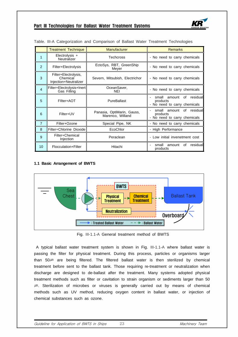
Table. III-A Categorization and Comparison of Ballast Water Treatment Technologies
Treatment Technique Manufacturer Remarks
1 Electrolysis + Neutralizer Techcross - No need to carry chemicals
2 Filter+Electrolysis EctoSys, RBT, GreenShipMeyer - No need to carry chemicals
3Filter+Electrolysis,
Chemical Injection+Neutralizer
Severn, Mitsubish, Electrichor - No need to carry chemicals
4 Filter+Electrolysis+Inert Gas Filling
OceanSaver, NEI - No need to carry chemicals
5 FIlter+AOT PureBallast - small amount of residual
products - No need to carry chemicals
6 Filter+UV Panasia, OptiMarin, Gauss, Marenco, Willand
- small amount of residual products
- No need to carry chemicals7 Filter+Ozone Special Pipe, NK - No need to carry chemicals8 Filter+Chlorine Dioxide EcoChlor - High Performance
9 Filter+Chemical Injection Peraclean - Low initial invenetment cost
10 Flocculation+Filter Hitachi - small amount of residual products
1.1 Basic Arrangement of BWTS
Fig. III-1.1-A General treatment method of BWTS
A typical ballast water treatment system is shown in Fig. III-1.1-A where ballast water is passing the filter for physical treatment. During this process, particles or organisms larger than 50㎛ are being filtered. The filtered ballast water is then sterilized by chemical treatment before sent to the ballast tank. Those requiring re-treatment or neutralization when discharge are designed to de-ballast after the treatment. Many systems adopted physical treatment methods such as filter or cavitation to strain organism or sediments larger than 50 ㎛. Sterilization of microbes or viruses is generally carried out by means of chemical methods such as UV method, reducing oxygen content in ballast water, or injection of chemical substances such as ozone.

Part III Technologies for Ballast Water Treatment Systems
Guideline for Application of BWTS in Ships Machinery Team24
BWTSSea
Chest Ballast TankFilter
Photo Catalysis
Overboard
: Treated Ballast Water : Ballast Water
BWTSSea
Chest Ballast TankGas, Hydroxyl
Ion
Cavitation
Filter
Overboard
: Treated Ballast Water : Ballast Water
1.2 Treatment Using Filter + Photo Catalysis
Fig. III-1.2-A Treatment Process Using Filter + UV
This method generally uses a filter and Photo Catalysis to treat ballast water. The advantage of this method is that it does not use any chemical substances. Fig. III-1.2-A shows the outline of the treatment method. The system first eliminates large aquatic organisms by the filter and then, sterilizes the left-out aquatic organisms or viruses with radicals that are produced when titanium dioxide is exposed to the light. Radical means an atom or molecule containing unpaired electron.
1.3 Treatment Using Filter + Cavitation + N2
Fig. III-1.3-A Treatment process using Filter + Cavitation + N2
This system consists of a filter, a cavitation unit and an N2 generator. This method does not make use of any active substances. Fig. III-1.3-A shows the outline of the treatment method. The ballast water passes through the filter where aquatic organism or sediments larger than 50㎛ are filtered. The filtered ballast water is then sanitized by the cavitation unit, and then the ballast water is further sanitized by adding electrolysis-produced hydroxyl ion and N2 gas into the ballast tank.
Part III Technologies for Ballast Water Treatment Systems
Guideline for Application of BWTS in Ships Machinery Team25
BWTSSea
Chest Ballast TankInert Gas Injection
Water Quality Control
Overboard
: Treated Ballast Water : Ballast Water
BWTSSea
Chest Ballast TankElectrolysis
NeutralizationOverboard
: Treated Ballast Water : Ballast Water
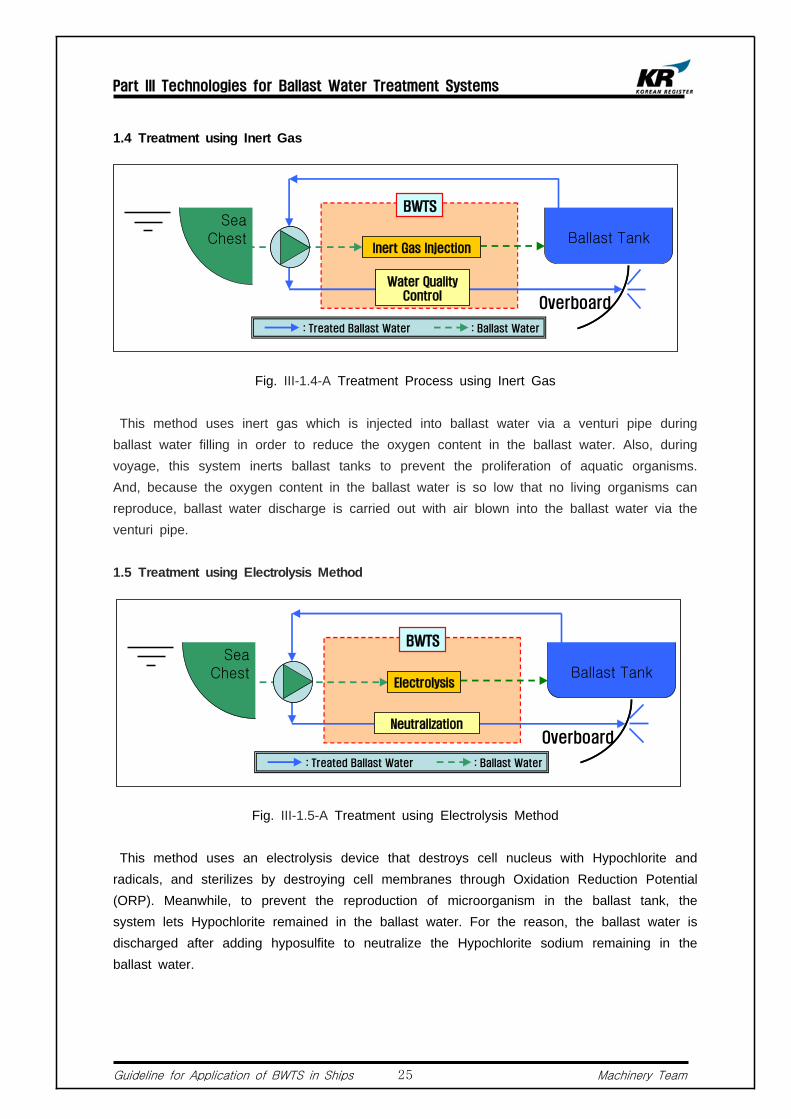
1.4 Treatment using Inert Gas
Fig. III-1.4-A Treatment Process using Inert Gas
This method uses inert gas which is injected into ballast water via a venturi pipe during ballast water filling in order to reduce the oxygen content in the ballast water. Also, during voyage, this system inerts ballast tanks to prevent the proliferation of aquatic organisms. And, because the oxygen content in the ballast water is so low that no living organisms can reproduce, ballast water discharge is carried out with air blown into the ballast water via the venturi pipe.
1.5 Treatment using Electrolysis Method
Fig. III-1.5-A Treatment using Electrolysis Method
This method uses an electrolysis device that destroys cell nucleus with Hypochlorite and radicals, and sterilizes by destroying cell membranes through Oxidation Reduction Potential (ORP). Meanwhile, to prevent the reproduction of microorganism in the ballast tank, the system lets Hypochlorite remained in the ballast water. For the reason, the ballast water is discharged after adding hyposulfite to neutralize the Hypochlorite sodium remaining in the ballast water.

Part III Technologies for Ballast Water Treatment Systems
Guideline for Application of BWTS in Ships Machinery Team26
BWTSSea
Chest Ballast Tank
Overboard
: Treated Ballast Water : Ballast Water
필터Filter
Stir Magnetic Separation
BWTSSea
Chest Ballast TankFilter UV
Overboard
: Treated Ballast Water : Ballast Water
1.6 Treatment using Filter + Magnetic Separation
Fig. III-1.6-A Treatment Process using Filter + Magnetic Separation
This system consists of a stirring facility, a magnetic separation device and a filter. This method treats ballast water by inserting magnetic substances in the ballast water during ballast uptake to induce stir and magnetic separation. This system uses no chemicals nor changes the property of ballast water and therefore no re-treatment or neutralization is required.
1.7 Treatment using FIlter + UV
Fig. III-1.7-A Treatment using FIlter + UV
This system is composed of a filter and a UV unit. This system first eliminates large aquatic organism and sediments by the filter without using any chemical substances and then sterilizes microbes and viruses by UV. During discharge, the ballast water is passing the UV unit again to make sure all the microbes and viruses that might have been survived are completely sterilized.

Part III Technologies for Ballast Water Treatment Systems
Guideline for Application of BWTS in Ships Machinery Team27
Characteristics of BWTS by Manufacturers
Below descriptions for various ballast water treatment systems are based on each
manufacturer's website and brochures. Readers should note that there may be changes or
updates in their system configuration, performance, explosion protection design, etc. For
additional information on each products, please refer to Appendix E.
2.1 PureBallast System(Norway / MEPC 56(Final Approval))
2.1.1 General
1) PureBallast is a ballast water treatment system developed in Norway. This technology was submitted for approval at MEPC 55 and received Basic Approval and Final Approval under the name of Norway at MEPC 56 on July 2007. The system consists of a filer and AOT (Advanced Oxidation Technology) units .
2.1.2 Characteristics
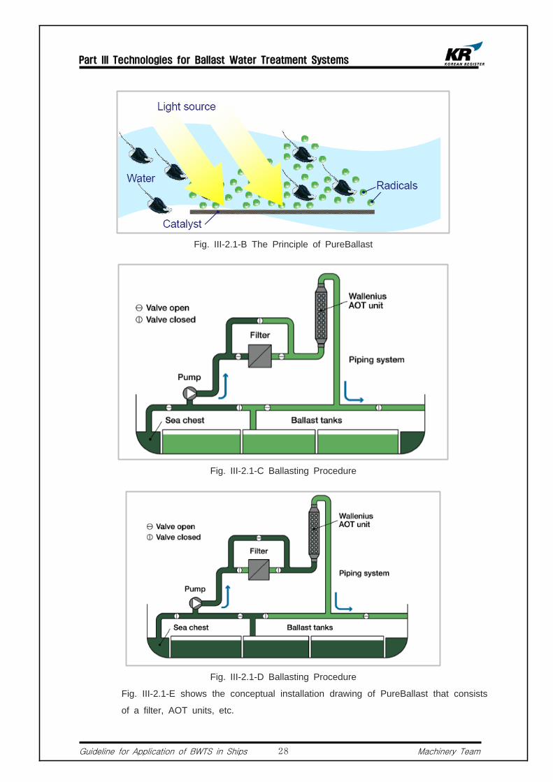
1) A 50 μm self-cleaning filter is used during ballasting operations. (During
de-ballasting, the filter is bypassed.) This not only blocks the intake of larger
organisms, but also reduces the amount of sediments in the ballast water tanks.
2) Depending on the system flow rate, one or more AOT units comprise the active
stage of PureBallast treatment, in which generated radicals that neutralize
microorganisms and other organic matter.
3) The AOT can treat ballast water without generating toxic substances and shows
not only stronger oxidizing power compare with other oxidizing agents such as
chlorine, chlorine dioxide, or calcium permanganate but also quick reaction without
leaving toxic substances or residuals. Fig. III-2.1-C and III-2.1-D are diagrams
showing ballast water flow during treatment stage.
Fig. III-2.1-A The Principle of PureBallast
Part III Technologies for Ballast Water Treatment Systems
Guideline for Application of BWTS in Ships Machinery Team28
Fig. III-2.1-B The Principle of PureBallast
Fig. III-2.1-C Ballasting Procedure
Fig. III-2.1-D Ballasting Procedure
Fig. III-2.1-E shows the conceptual installation drawing of PureBallast that consists
of a filter, AOT units, etc.

Part III Technologies for Ballast Water Treatment Systems
Guideline for Application of BWTS in Ships Machinery Team29
Fig. III-2.1-E Conceptual Drawing of PureBallast
Fig. III-2.1-F AOT Assembly Fig. III-2.1-G Filter
Fig. III-2.1-H Table of Electric Consumption
Part III Technologies for Ballast Water Treatment Systems
Guideline for Application of BWTS in Ships Machinery Team30
2.2 Electro-Cleen(Korea / MEPC 58(Final Approval))
2.2.1 General
1) Techcross Inc's Electro-Cleen System was granted Basic Approval of ballast water
treatment system that makes use of active substance by IMO at MEPC 54th on Mar.
2006 and received Final Approval at MEPC 58th on Oct. 2008.
2.2.2 Characteristics
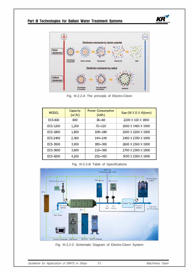
1) Electro-Cleen System uses electrolysis with application of electric current. In the
process of electrolysis, proton ion and hydroxide ion are being released from positive
anode and negative anode, respectively, where sufficient potential of disinfection
forms around the positive anode and the hydroxide ion released from the negative
anode has an outstanding performance in hydrolysing organisms. In other words,
when electrolyze water, it decomposes into various kinds of radicals such as OH,
HCO, O2, H2O2, O3, and Cl- . And since the radicals have high potential differences,
they react fast with almost all organisms.
2) Although radicals are unstable substances that only last for very short period of time,
from few millionth seconds to few seconds, they destroy organisms instantaneously.
Also, residual chlorine prohibits the re-growth of microorganisms in the ballast tank. A
neutralization unit is installed in the discharge line to neutralize the chlorine content
down to nearly zero when de-ballasting,
2.2.3 Components
1) Control PC : controls the ballast water treatment system.2) ECU : Eletro-Chamber Unit : is a core component of the ballast water treatment
system where electrolysis process actually occurs by high-voltage direct current transmitted from a Rectifier.
3) Power Distributor : distributes power to the ballast water treatment system.4) Rectifier : converts the input power supplied by the power distributor to high-voltage
direct current. 5) Auto Neutralization Unit : automatically controls the chlorine contents by a TSU
(TRO(total residual oxidant) sensor unit) during de-ballasting.
Part III Technologies for Ballast Water Treatment Systems
Guideline for Application of BWTS in Ships Machinery Team31
Fig. III-2.2-A The principle of Electro-Cleen
Fig. III-2.2-B Table of Specifications
Fig. III-2.2-C Schematic Diagram of Electro-Cleen System

Part III Technologies for Ballast Water Treatment Systems
Guideline for Application of BWTS in Ships Machinery Team32
2.3 OceanSaver(Norway / MEPC 58(Final Approval))
2.3.1 General
1) Developed by OceanSaver in Norway, this system was granted basic approval at MEPC 57th on Mar. 2008 followed by final approval for ballast water management system that make use of active substances on Oct. 2008.
2.3.2 Characteristics
1) OceanSaver was launched in 2007 as a technology that treats ballast water by pre-filtering
ballast water followed by cavitation and filling nitrogen gas in the ballast tank.
2) However, to enhance its performance, an electrolysis unit was added to the system. The
additional components are as follows :
a. Mechanical Filtration Unit
b. C3T Unit : Hydrodynamic cavitation
c. C2E Unit : Activated water
d. Nitrogen(N2) Supersaturation unit
3) Until the introduction of the electrolysis unit in 2006, the C3T was the main component of
the treatment system. The C3T, as shown in Fig. III-2.3-A, is a device that induces
cavitation inside the chamber to destroy micro-organisms.
4) Because this unit shows low efficiency of destroying micro-organisms and there is a
chance of re-growth of micro-organisms in the ballast tank, the system requires the
ballast to pass the C3T during de-ballasting. Fig. III-2.3-B and III-2.3-C show the
process of ballasting and de-ballasting, respectively.
Fig. III-2.3-A Cavitation Unit of OceanSaver C3T(600m3/h)

Part III Technologies for Ballast Water Treatment Systems
Guideline for Application of BWTS in Ships Machinery Team33
Fig. III-2.3-B Ballasting Procedure of OceanSaver
Fig. III-2.3-C De-ballasting Procedure of OceanSaver
Fig. III-2.3-D Conceptual Installation Drawing of OceanSaver

Part III Technologies for Ballast Water Treatment Systems
Guideline for Application of BWTS in Ships Machinery Team34
Fig. III-2.3-E Conceptual Installation Drawing of OceanSaver
2.4 RWO(Germany / MEPC 59(Final Approval))
2.4.1 General
1) CleanBallast developed by RWO received Final Approval at MEPC 59th. This
system consists of 2 major treatment processes, filter and electrolysis.
2.4.2 Characteristics
1) This system consists of a filtering device called DiskFilter that primarily filters solid
matters and sediments, and EctoSys (Electrolysis Unit) that secondarily treats the
remaining micro-organisms. Also, during de-ballasting, the treated ballast water is
being sent to the EctoSys again to destroy the micro-organisms that might have
not been fully destroyed or re-grown in the ballast tank.
2) FIg. III-2.4-A shows a ballasting procedure where organisms greater than 50㎛ are
filtered by the DiskFilter and those smaller than 50㎛ are destroyed by the
EctoSys. Whereas Fig. III-2.4-B shows the de-ballasting procedure where the
treated ballast water is being discharged after passing the EctoSys. Also, III-2.4-C,
III-2.4-D and III-2.4-E are the picture of Monitor, DiskFilter and EctoSys
respectively. The specifications of main treatment system are as follows :
a. Power Consumption : Min. 0.008kWh/m3 ~ Max. 0.1kWh/m3
b. Pressure Drop : 0.6 ~ 1.3bar
c. System Capacities : 100 ~ 7,000m3/h

Part III Technologies for Ballast Water Treatment Systems
Guideline for Application of BWTS in Ships Machinery Team35
Fig. III-2.4-A Ballasting Procedure
Fig. III-2.4-B De-ballasting Procedure
Fig. III-2.4-C Monitor Fig. III-2.4-D EctoSys
Part III Technologies for Ballast Water Treatment Systems
Guideline for Application of BWTS in Ships Machinery Team36
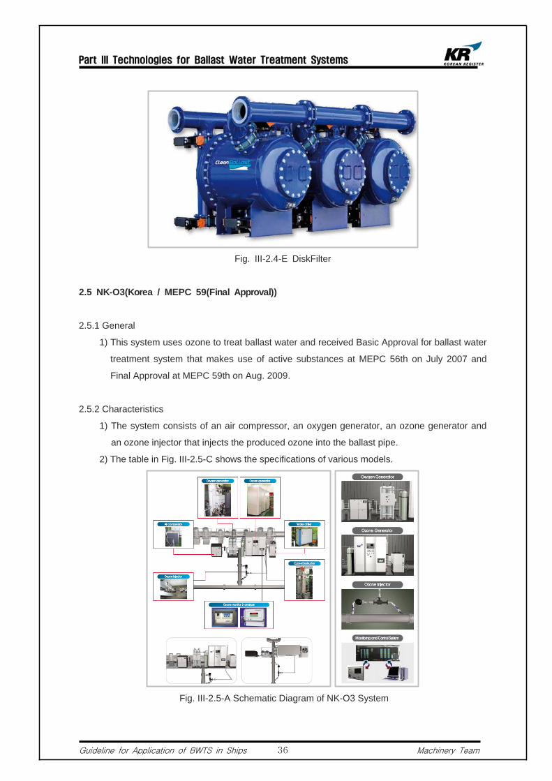
Fig. III-2.4-E DiskFilter
2.5 NK-O3(Korea / MEPC 59(Final Approval))
2.5.1 General
1) This system uses ozone to treat ballast water and received Basic Approval for ballast water
treatment system that makes use of active substances at MEPC 56th on July 2007 and
Final Approval at MEPC 59th on Aug. 2009.
2.5.2 Characteristics
1) The system consists of an air compressor, an oxygen generator, an ozone generator and
an ozone injector that injects the produced ozone into the ballast pipe.
2) The table in Fig. III-2.5-C shows the specifications of various models.
Fig. III-2.5-A Schematic Diagram of NK-O3 System

Part III Technologies for Ballast Water Treatment Systems
Guideline for Application of BWTS in Ships Machinery Team37
Fig. III-2.5-B Piping Arrangement for NK-O3
Fig. III-2.5-C Table of Specifications
2.6 Hitachi-ClearBallast(Japan / MEPC 59(Final Approval))
2.6.1 General
1) CleanBallast developed by Hitachi. Ltd in Japan was granted Basic Approval at
MEPC 57th on Mar. 2008 followed by Final Approval at MEPC 59.
2.7.2 Characteristics
1) This treatment system, as shown in Fig.III-2.6-A, treats ballast water by combining
magnetic separation technology and coagulation technology. In contrast to
sterilizatoin-type approaches, the coagulation method does not use chlorine, ozone,
ultraviolet light, or other disinfectants and therefore the risk of residual chemicals
causing secondary contamination is removed. The treatment take place in the
following order : insertion of flocculation agent, magnetic separation, and filter.
Magnetic powder and flocculation agents are added to sea water and the water is

Part III Technologies for Ballast Water Treatment Systems
Guideline for Application of BWTS in Ships Machinery Team38
roiled to form magnetized floc consisting of plankton, bacteria, mud, and other
materials. When passed through a magnetic separator, the floc adheres to
magnetic disks. Finally, the treated water is filtered by a filter separator, before
being pumped into the ballast tanks.
Fig. III-2.6-A Treatment Principle of ClearBallast
Fig. III-2.6-B Treatment Procedure of ClearBallast
Part III Technologies for Ballast Water Treatment Systems
Guideline for Application of BWTS in Ships Machinery Team39
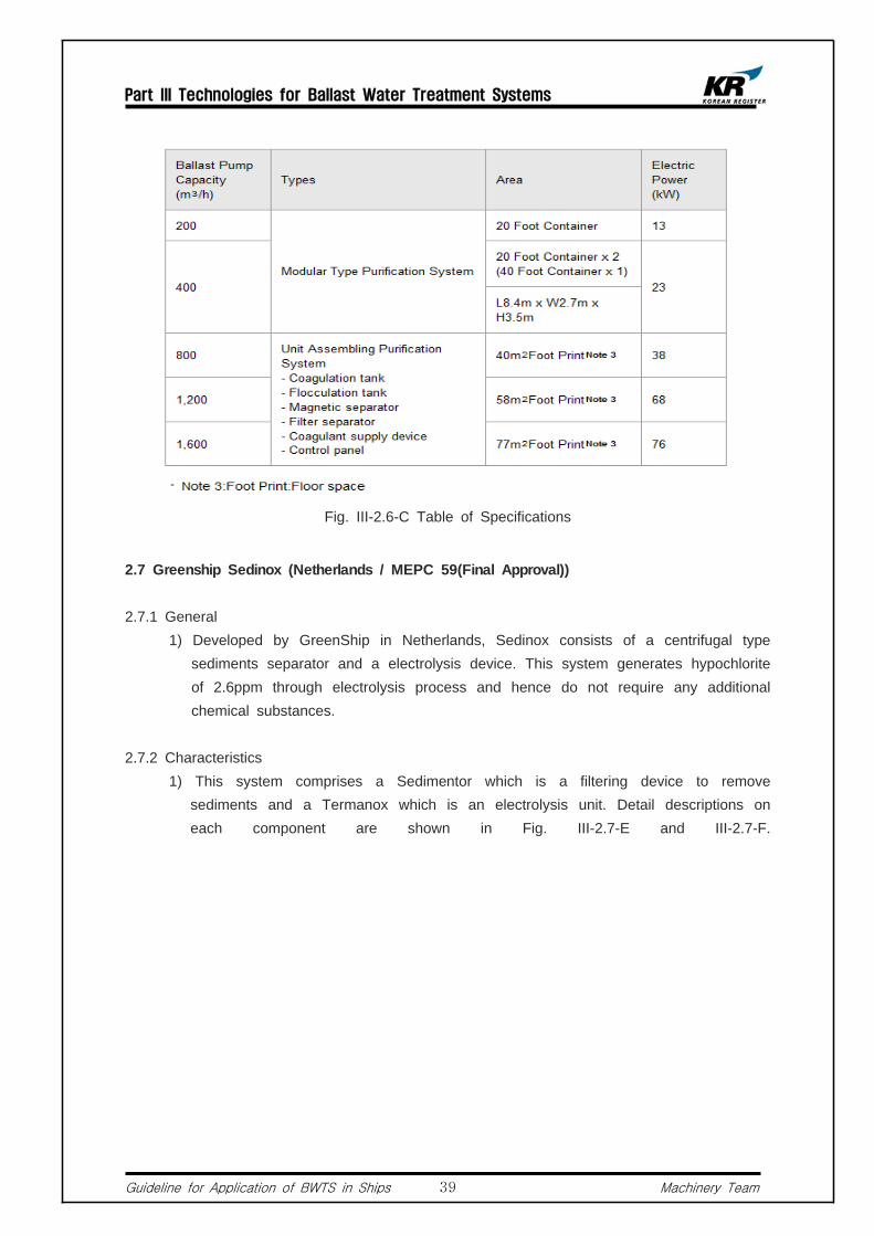
Fig. III-2.6-C Table of Specifications
2.7 Greenship Sedinox (Netherlands / MEPC 59(Final Approval))
2.7.1 General 1) Developed by GreenShip in Netherlands, Sedinox consists of a centrifugal type
sediments separator and a electrolysis device. This system generates hypochlorite of 2.6ppm through electrolysis process and hence do not require any additional chemical substances.
2.7.2 Characteristics 1) This system comprises a Sedimentor which is a filtering device to remove
sediments and a Termanox which is an electrolysis unit. Detail descriptions on each component are shown in Fig. III-2.7-E and III-2.7-F.

Part III Technologies for Ballast Water Treatment Systems
Guideline for Application of BWTS in Ships Machinery Team40
Fig. III-2.7-A Sedimentor(100m3/hr) Fig. III-2.7-B Termanox(100m3/hr)
2) Fig. III-2.8-C is a picture showing actual installation of Sedinox onboard and Fig. III-2.8-D shows the conceptual drawing of a system having 300m3/h capacity.
Fig. III-2.7-C Installation Fig. III-2.7-D Configuration of 300m3/h Model
Part III Technologies for Ballast Water Treatment Systems
Guideline for Application of BWTS in Ships Machinery Team41
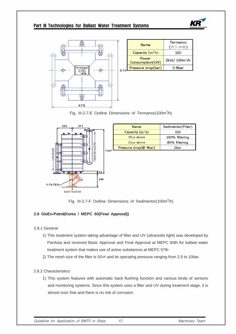
Fig. III-2.7-E Outline Dimensions of Termanox(100m3/h)
FIg. III-2.7-F Outline Dimensions of Sedimentor(100m3/h)
2.8 GloEn-Patrol(Korea / MEPC 60(Final Approval))
2.8.1 General
1) This treatment system taking advantage of filter and UV (ultraviolet light) was developed by
PanAsia and received Basic Approval and Final Approval at MEPC 60th for ballast water
treatment system that makes use of active substances at MEPC 57th
2) The mesh size of the filter is 50㎛ and its operating pressure ranging from 2.5 to 10bar.
2.8.2 Characteristics
1) This system features with automatic back flushing function and various kinds of sensors
and monitoring systems. Since this system uses a filter and UV during treatment stage, it is
almost toxic free and there is no risk of corrosion.

Part III Technologies for Ballast Water Treatment Systems
Guideline for Application of BWTS in Ships Machinery Team42
Fig. III-2.8-A Schematic Diagram of GloEn-Patrol
Fig. III-2.8-B Isometric Drawing of GloEn-Patrol
Fig. III-2.8-C Table of Specifications

Part III Technologies for Ballast Water Treatment Systems
Guideline for Application of BWTS in Ships Machinery Team43
2.9 Resource Ballast Tech. Sys.(South Africa / MEPC 60(Final Approval))
2.9.1 General
1) This system was developed by Resource Ballast Technology(RBT) in South Africa and granted Basic Approval for ballast water treatment system that makes use of active substances at MEPC 57th on Mar. 2008 followed by Final Approval at MEPC 60th.
2.9.2 Characteristics
1) The cavitation and the application of the disinfectants all take place within the reactor vessels (RBT), while the filter removes larger organisms and particulate matter. The cavitation creates very strong sheer forces that effectively rupture the aquatic organisms. Electrodes mounted inside the reactor vessels produce sodium hypochlorite at a concentration of <1.0 ppm. A small ozone generator incorporated in the control system provides ozone at <1.0 ppm. With both sodium hypochlorite and ozone systems complete disinfection is achieved.
2) III-2.9-A shows the treatment process of the system. And Fig. III-2.9 shows the specifications of the system that comes in different sizes.
+
Fig. III-2.9-A Process Flow Chart
Fig. III-2.9-B Table of Specifications

Part III Technologies for Ballast Water Treatment Systems
Guideline for Application of BWTS in Ships Machinery Team44
Fig. III-2.9-C Filter Fig. III-2.9-D Electro-Chemical Reactor
2.10 JFE(Japan / MEPC 60(Final Approval))
2.10.1 General
1) Developed by JFE in Japan, this system uses the combination of filter, cavitation
and sodium hypochlorite. Granted Basic Approval at MEPC 58th and Final
Approval at MEPC 60th.
2.10.2 Characteristics
1) This system treats ballast water by injecting sodium hypochlorite that is stored
onboard a ship at a concentrate of 30 ppm into the ballast water. Fig. III-2.10-A
and III-2.10-B show the treatment processes during ballasting and de-ballasting.
FIg. III-2.10-A Treatment Process during Ballasting

Part III Technologies for Ballast Water Treatment Systems
Guideline for Application of BWTS in Ships Machinery Team45
FIg. III-2.10-B Treatment Process during De-ballasting
FIg. III-2.10-C Main Components of the Treatment System
Fig. III-2.10-D Overall Flow Chart of the System

Part III Technologies for Ballast Water Treatment Systems
Guideline for Application of BWTS in Ships Machinery Team46
2.11 EcoBallast(Korea / MEPC 60(Final Approval))
2.11.1 General
1) Developed by Hyundai Heavy Industries Co. Ltd., EcoBallast System was granted
Final Approval at MEPC 60th. This system is composed of two main units : a
filter and a UV reactor. The system is controlled by a programmable logic
controller installed in the control panel. This system is considered as
environment-friendly since it does not use any chemicals or active substances.
2.11.2 System Configuration
1) Control Unit including System Valves and Instruments
2) Auto Back-flushing Filter
3) UV Reactor
4) UV Cleaning Unit
5) By-pass line for Auto Back-flushing filter and UV Reactor
Fig. III-2.11.-A Schematic System Diagram
2.11.3 Auto Back-flushing Filter
1) The auto back-flushing filter is driven by a pressure difference between inlet and
outlet of the filter, that is generated by a back-flushing pump. The specifications
and configuration of the auto back-flushing filter are as follows :
Table III-2.11-B Specifications of Auto Back-flushing Filter
Part III Technologies for Ballast Water Treatment Systems
Guideline for Application of BWTS in Ships Machinery Team47
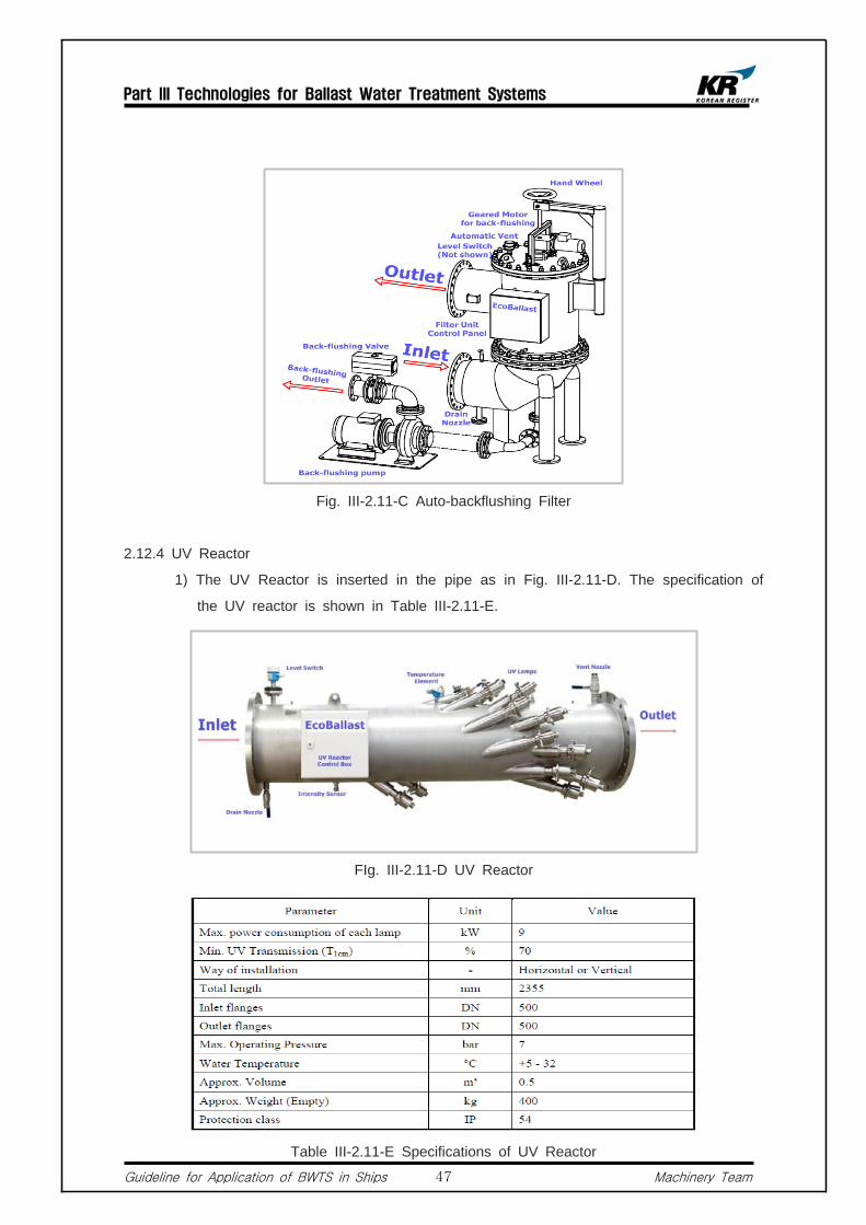
Fig. III-2.11-C Auto-backflushing Filter
2.12.4 UV Reactor
1) The UV Reactor is inserted in the pipe as in Fig. III-2.11-D. The specification of
the UV reactor is shown in Table III-2.11-E.
FIg. III-2.11-D UV Reactor
Table III-2.11-E Specifications of UV Reactor
Part III Technologies for Ballast Water Treatment Systems
Guideline for Application of BWTS in Ships Machinery Team48
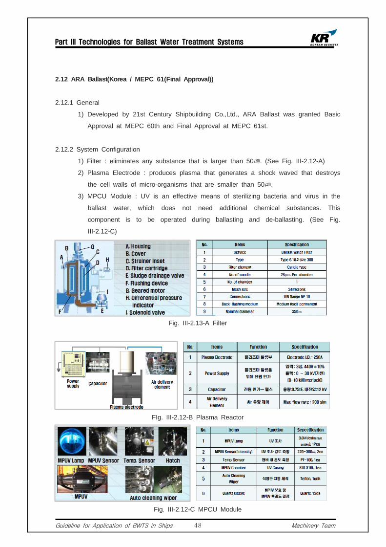
2.12 ARA Ballast(Korea / MEPC 61(Final Approval))
2.12.1 General
1) Developed by 21st Century Shipbuilding Co.,Ltd., ARA Ballast was granted Basic
Approval at MEPC 60th and Final Approval at MEPC 61st.
2.12.2 System Configuration
1) Filter : eliminates any substance that is larger than 50㎛. (See Fig. III-2.12-A)
2) Plasma Electrode : produces plasma that generates a shock waved that destroys
the cell walls of micro-organisms that are smaller than 50㎛.
3) MPCU Module : UV is an effective means of sterilizing bacteria and virus in the
ballast water, which does not need additional chemical substances. This
component is to be operated during ballasting and de-ballasting. (See Fig.
III-2.12-C)
Fig. III-2.13-A Filter
FIg. III-2.12-B Plasma Reactor
Fig. III-2.12-C MPCU Module
Part III Technologies for Ballast Water Treatment Systems
Guideline for Application of BWTS in Ships Machinery Team49
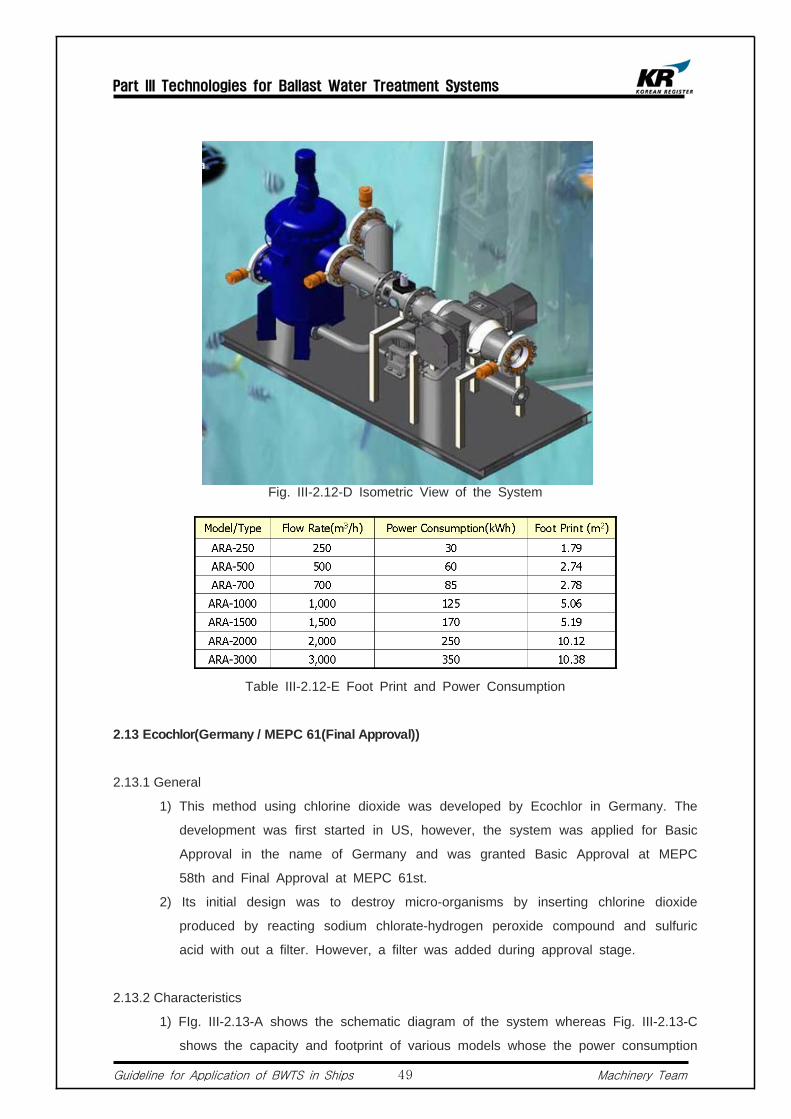
Fig. III-2.12-D Isometric View of the System
Table III-2.12-E Foot Print and Power Consumption
2.13 Ecochlor(Germany / MEPC 61(Final Approval))
2.13.1 General
1) This method using chlorine dioxide was developed by Ecochlor in Germany. The
development was first started in US, however, the system was applied for Basic
Approval in the name of Germany and was granted Basic Approval at MEPC
58th and Final Approval at MEPC 61st.
2) Its initial design was to destroy micro-organisms by inserting chlorine dioxide
produced by reacting sodium chlorate-hydrogen peroxide compound and sulfuric
acid with out a filter. However, a filter was added during approval stage.
2.13.2 Characteristics
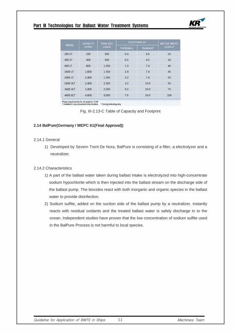
1) FIg. III-2.13-A shows the schematic diagram of the system whereas Fig. III-2.13-C
shows the capacity and footprint of various models whose the power consumption
Part III Technologies for Ballast Water Treatment Systems
Guideline for Application of BWTS in Ships Machinery Team50
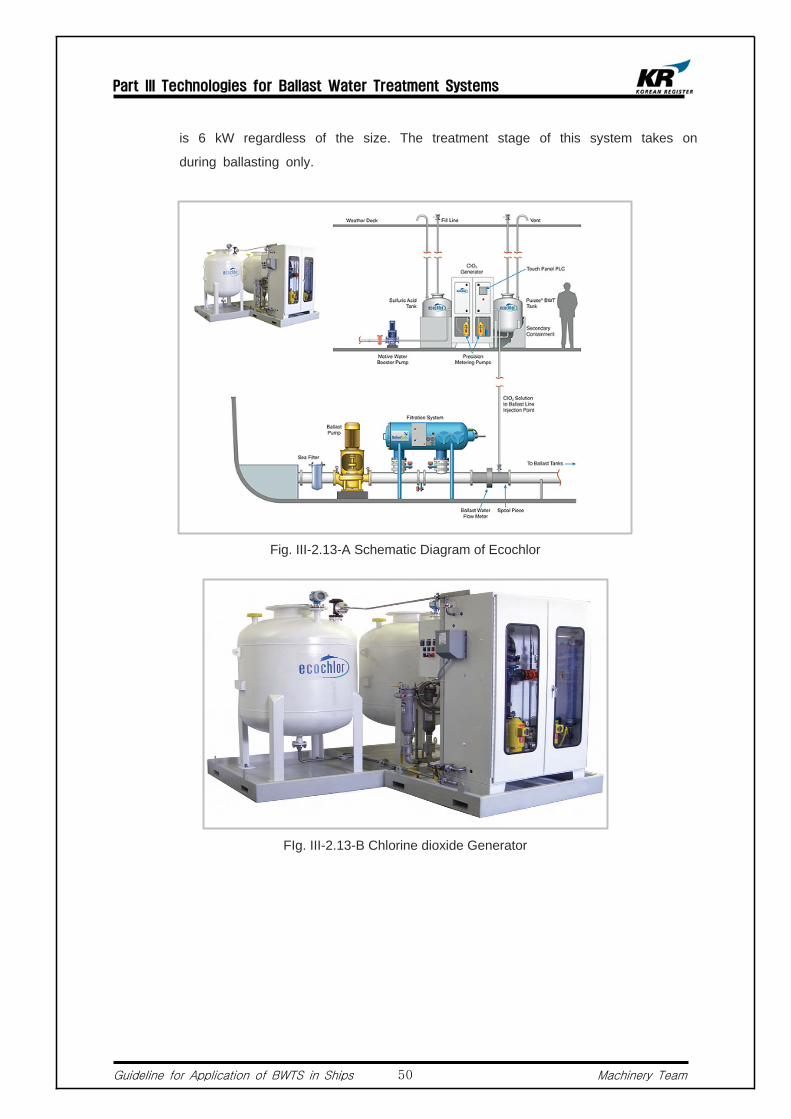
is 6 kW regardless of the size. The treatment stage of this system takes on
during ballasting only.
Fig. III-2.13-A Schematic Diagram of Ecochlor
FIg. III-2.13-B Chlorine dioxide Generator
Part III Technologies for Ballast Water Treatment Systems
Guideline for Application of BWTS in Ships Machinery Team51
Fig. III-2.13-C Table of Capacity and Footprint
2.14 BalPure(Germany / MEPC 61(Final Approval))
2.14.1 General
1) Developed by Severn Trent De Nora, BalPure is consisting of a filter, a electrolyzer and a
neutralizer.
2.14.2 Characteristics
1) A part of the ballast water taken during ballast intake is electrolyzed into high-concentrate
sodium hypochlorite which is then injected into the ballast stream on the discharge side of
the ballast pump. The biocides react with both inorganic and organic species in the ballast
water to provide disinfection.
2) Sodium sulfite, added on the suction side of the ballast pump by a neutralizer, instantly
reacts with residual oxidants and the treated ballast water is safely discharge in to the
ocean. Independent studies have proven that the low concentration of sodium sulfite used
in the BalPure Process is not harmful to local species.

Part III Technologies for Ballast Water Treatment Systems
Guideline for Application of BWTS in Ships Machinery Team52
FIg. III-2.14-A BalPure Ballast Water Treatment System
3) Fig. II-2.14-A, III-2.14-B and III-2.14-C show the outlines of the system, ballast water
treatment procedure during intake, and ballast water discharge procedure, respectively.
Fig. III-2.14-B Ballasting Procedure for BalPure

Part III Technologies for Ballast Water Treatment Systems
Guideline for Application of BWTS in Ships Machinery Team53
Fig. III-2.14-C De-ballasting Procedure for BalPure
Fig. III-2.14-D Table of Specifications
2.15 OceanGuard(Norway / MEPC 61(Final Approval))
2.15.1 General
1) OceanGuard received Basic Approval at MEPC 60th and Final Approval at MEPC61st.
2) The system was developed by a technical co-operation between Headway Technology.
Co. Ltd., and Harbin Engineering University.
2.15.2 Characteristics
1) This treatment system uses an AOP (Advanced Oxidation Process) technology which is
the combination of electrolysis and ultrasonic wave type that destroys micro-organisms
through an oxidative breakdown initiated by powerful oxidizing species such as hydroxyl
radicals.
2) When electrolyze sea water, it decomposes into various radicals such as OH, HCO, O2,
H2O2, O3, and OCl- radical. These radicals react fast with almost all organisms due to high

Part III Technologies for Ballast Water Treatment Systems
Guideline for Application of BWTS in Ships Machinery Team54
potential differences. Although radicals are unstable substances that only last for very short
period of time, from few millionth seconds to few seconds, they destroy organisms
instantaneously. Also, residual chlorine prohibits the re-growth of microorganisms in the
ballast tank.
Fig. III-2.15-A Isometric View of OceanGuard
3) This system also uses ultrasonic wave that produces a high intensive wave in the treated
area to kill the remaining micro-organisms in the ballast water. Fig. III-2.15-A shows the
piping arrangement of the system.
2.15.3 System Configuration
1) Control Unit : The control unit is responsible for regulating the entire system including the monitoring of a variety of sensor signals, dealing with any alarm signals and automatically controlling system startup and shutdown sequences. The Control Unit includes all procedures needed for system operation, monitoring the system, including the working condition of various parts as well as the data and conditions reported by real time inspection from the various sensors. (See Fig. III-2.15-B)
2) Filter : The filter has 50 microns precision filtration. The filter can accomplish both automatic backflush and filtering at the same time, removing any biological matter larger than 50 microns. It is able to prevent large-sized organism from entering ballast tank, so as to reduce the sedimentss inside.
3) EUT : The EUT Unit, which is the core part of OceanGuard, comprises two parts: Electro catalysis Unit and Ultrasonic Unit. The Electrocatalysis Unit is able to produce large number of Hydroxyl and other highly active oxidizing substances, and has a super long lifetime. The Ultrasonic Unit can produce a high intensity wave in a treated area instantly, killing biological material, including bacteria. (See Fig. III-2.15-D)

Part III Technologies for Ballast Water Treatment Systems
Guideline for Application of BWTS in Ships Machinery Team55
Fig. III-2.15-B Control Unit Fig. III-2.15-C Filter Fig. III-2.15-D EUT Units
Fig. III-2.15-E Table of Capacity, Size, and Power Consumption
Part IV Application of Ballast Water Treatment Systems
Guideline for Application of BWTS in Ships Machinery Team56
Part IV Application of Ballast Water Treatment Systems
Ships other than Tankers
1. General
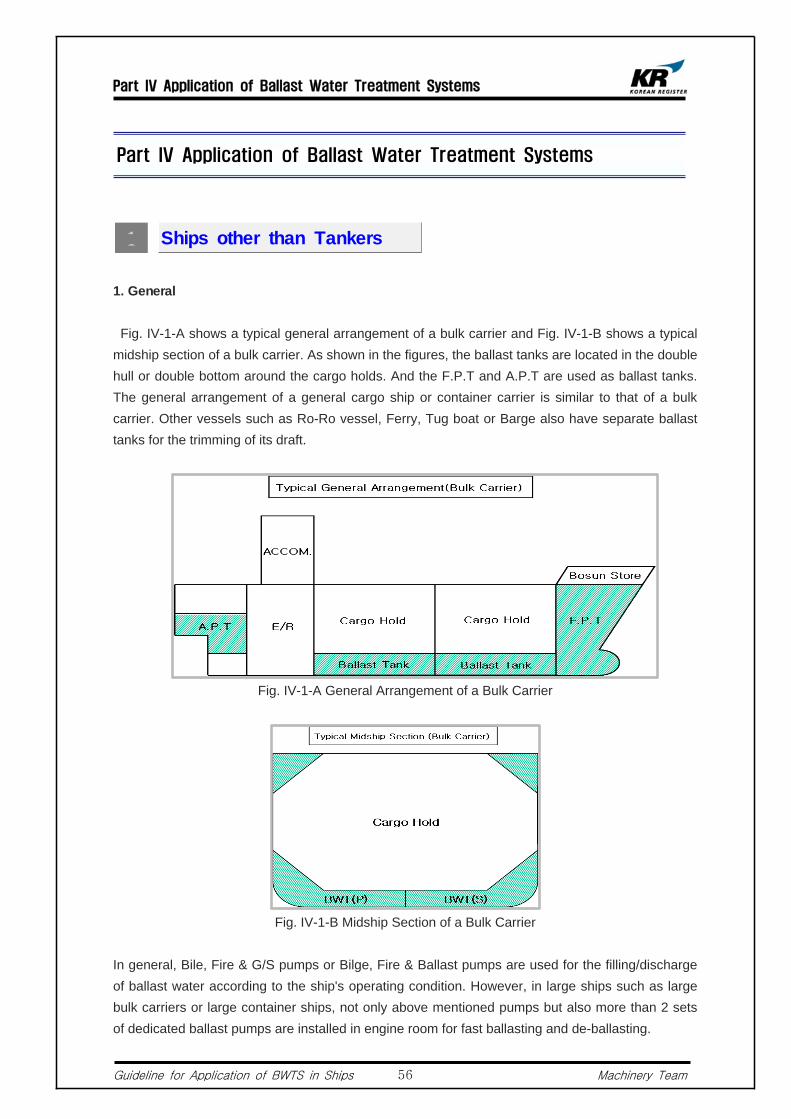
Fig. IV-1-A shows a typical general arrangement of a bulk carrier and Fig. IV-1-B shows a typical midship section of a bulk carrier. As shown in the figures, the ballast tanks are located in the double hull or double bottom around the cargo holds. And the F.P.T and A.P.T are used as ballast tanks. The general arrangement of a general cargo ship or container carrier is similar to that of a bulk carrier. Other vessels such as Ro-Ro vessel, Ferry, Tug boat or Barge also have separate ballast tanks for the trimming of its draft.
Fig. IV-1-A General Arrangement of a Bulk Carrier
Fig. IV-1-B Midship Section of a Bulk Carrier
In general, Bile, Fire & G/S pumps or Bilge, Fire & Ballast pumps are used for the filling/discharge of ballast water according to the ship's operating condition. However, in large ships such as large bulk carriers or large container ships, not only above mentioned pumps but also more than 2 sets of dedicated ballast pumps are installed in engine room for fast ballasting and de-ballasting.

Part IV Application of Ballast Water Treatment Systems
Guideline for Application of BWTS in Ships Machinery Team57
2. Related Regulations
2.1 KR Rules for the Classification of Steel Ships (Hereinafter the KR-Rules) Part 5 Chapter 6
402.2.(2)
All ballast tanks are to be connected to at least two(2) power driven ballast pumps where one of
which may be driven by a propulsion unit. Bilge, sanitary or general service pumps driven by
independent power may be accepted as independent-power ballast pumps, provided that they
are connected properly to the line. However, gravity discharge from top side tanks are to be
complied with 302. 2 (1) (B) of the Guidance. And, where cargo pump is arranged for
de-ballasting in emergency as Pt 7, Ch 1, 1003. 2 (2), the cargo pump may be accepted as
one(1) independent power ballast pumps.
2.2 KR-Rules Part 5 Chapter 6 406.7
2.2.1 Ballast piping system is to be provided with a suitable provision such as a non-return valve or
a stop valve which can be kept closed at all times excluding the time of ballasting and
de-ballasting and which is provided with an indicator to show whether it is open or closed, in
order to prevent the possibility of water inadvertently passing from the sea to the ballast tanks
or of ballast passing from one ballast tank to another. Where butterfly valves(except remote
control valves) are used, they are to be of type with positive holding arrangements, or
equivalents, that will prevent movement of the valve position due to vibration or flow of fluids.
2.2.2 Remote control valves, where fitted, are to be arranged so that they will close and remain
closed in the event of loss of control power. Alternatively, the remote control valves may
remain in the last ordered position upon loss of power, provided that there is a readily
accessible manual means to the valves upon loss of power. Remote control valves are to be
clearly identified as to the tanks they serve and are to be provided with position indicators at
the ballast control station.
2.3 KR-Rules Part 5 Chapter 6 406.7
In case where gravitational ballasting/de-ballasting is intended by using sea chests provided in
the exclusive ballast tanks, double stop valves being operable from a position on the freeboard
deck are to be provided.

Part IV Application of Ballast Water Treatment Systems
Guideline for Application of BWTS in Ships Machinery Team58
2.4 KR Rules for the Classification of Mobile Offshore Units Chapter 10 104.7
2.4.1 The ballast system of semi-submersible structure should comply with follows :
1) The ballast systems are to consist of two or more adequate means by way of pumps or other suitable apparatuses, and they are to be capable of ballasting and de-ballasting all compartments even when one of them is out of service.
2) The system is to be capable of raising the unit, starting from a level trim condition at the deepest normal operating draft, to the severe storm draft, or a greater distance as may be specified by the Society, within three hours.
3) Ballast pumps, ballast tank valves and sea chest valves are to be provided with a means of remote control from a central ballast control station.
3. Dangerous space
3.1 General Cargo Ships, Bulk Carriers, and Container Carriers When carrying flammable cargoes (SOLAS Reg. II-2/19) classified by IMSBC Code or IMDG
Code, according to IEC 60092-506, the cargo area and its ventilation duct are being designated as dangerous spaces. If carrying Class 2.1, 3(flash point≤23℃), 6.1(flash point≤23℃), 8 cargoes or Class 4.3 cargoes in bulk, 3-meter radius of the ventilation in/outlet is being designated as a dangerous space.
3.2 Ro-Ro Vessel, Car Carrier Although enclosed Ro-Ro or car spaces are categorized as dangerous spaces, if the area or
space is equipped with a mechanical ventilation of minimum 10 change-time per hour and an alarm system for the failure of ventilation, the dangerous space can be reduced to 450mm above each deck. In this case, electric equipment with sealing protection against spread of sparks (IP55 or above) and those whose maximum surface temperature is less than 200℃ are allowed to be installed above 450mm of each deck.
3.3 Specially Categorized Area In specially categorized area, regardless of ventilation capacity, all areas below the
compartment deck are considered dangerous spaces in addition to the requirements in above 3.2.
3.4 Dangerous Space other than Cargo Area Other than above mentioned areas, a battery room, a paint store and an acetylene store are
also considered as dangerous spaces.
3.5 Installation of BWTS in Confined Space The electrical installation of BWTS should, as far as practicable, be avoided in the dangerous
spaces mentioned in above 3.1~3.4. However, If the installation is necessary due to ships's structure, explosion-proof electrical equipment complying with the minimum explosion proof level of the area should be installed. When installed in enclosed Ro-Ro or Car spaces, except

Part IV Application of Ballast Water Treatment Systems
Guideline for Application of BWTS in Ships Machinery Team59
IIB T3 or higher, the installation should be located above 450mm of each platform. Also, the electrical equipment should be of IP55 or higher and its surface temperature should not exceed 200℃.
3.6 Please refer to Appendix A for explosion-proof levels and protection types for electrical installation sorted by cargo types and ship types.
4. Installation of BWTS
4.1 Installation in Engine Room Fig. IV-1-C shows the schematic diagram of BWTS installation in engine room. Excluding
tankers, most ship's, ballast tanks are considered safe spaces that there is no restriction whatsoever in relation to the installation of BWTS in engine room. However, If the BWTS is equipped with an ozone(O3) generator, an ozone detection device that activates alarm in case of leakage is required to be installed in which the ozone generator is installed. Also, due consideration should be given to O3 pipes to prevent leakage; for example, using double pipes or welded joint SUS pipes.
Fig. IV-1-C Installation of BWTS in E/R
4.2 Installation outside the Engine Room The BWTS may also be installed outside the engine room if installation space is not available in
engine room. Please refer to Appendix E and F for information about the minimum required installation space by manufacturers. Below Fig. IV-1-D is the schematic diagram of BWTS installation outside the E/R.
Fig. IV-1-D Installation of BWTS outside the E/R
Part IV Application of Ballast Water Treatment Systems
Guideline for Application of BWTS in Ships Machinery Team60
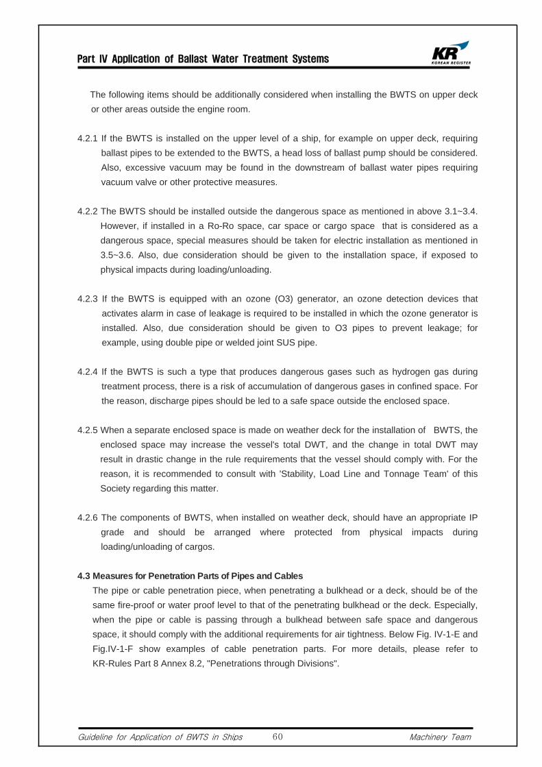
The following items should be additionally considered when installing the BWTS on upper deck or other areas outside the engine room.
4.2.1 If the BWTS is installed on the upper level of a ship, for example on upper deck, requiring ballast pipes to be extended to the BWTS, a head loss of ballast pump should be considered. Also, excessive vacuum may be found in the downstream of ballast water pipes requiring vacuum valve or other protective measures.
4.2.2 The BWTS should be installed outside the dangerous space as mentioned in above 3.1~3.4. However, if installed in a Ro-Ro space, car space or cargo space that is considered as a dangerous space, special measures should be taken for electric installation as mentioned in 3.5~3.6. Also, due consideration should be given to the installation space, if exposed to physical impacts during loading/unloading.
4.2.3 If the BWTS is equipped with an ozone (O3) generator, an ozone detection devices that activates alarm in case of leakage is required to be installed in which the ozone generator is installed. Also, due consideration should be given to O3 pipes to prevent leakage; for example, using double pipe or welded joint SUS pipe.
4.2.4 If the BWTS is such a type that produces dangerous gases such as hydrogen gas during treatment process, there is a risk of accumulation of dangerous gases in confined space. For the reason, discharge pipes should be led to a safe space outside the enclosed space.
4.2.5 When a separate enclosed space is made on weather deck for the installation of BWTS, the enclosed space may increase the vessel's total DWT, and the change in total DWT may result in drastic change in the rule requirements that the vessel should comply with. For the reason, it is recommended to consult with 'Stability, Load Line and Tonnage Team' of this Society regarding this matter.
4.2.6 The components of BWTS, when installed on weather deck, should have an appropriate IP grade and should be arranged where protected from physical impacts during loading/unloading of cargos.
4.3 Measures for Penetration Parts of Pipes and Cables The pipe or cable penetration piece, when penetrating a bulkhead or a deck, should be of the
same fire-proof or water proof level to that of the penetrating bulkhead or the deck. Especially, when the pipe or cable is passing through a bulkhead between safe space and dangerous space, it should comply with the additional requirements for air tightness. Below Fig. IV-1-E and Fig.IV-1-F show examples of cable penetration parts. For more details, please refer to KR-Rules Part 8 Annex 8.2, "Penetrations through Divisions".
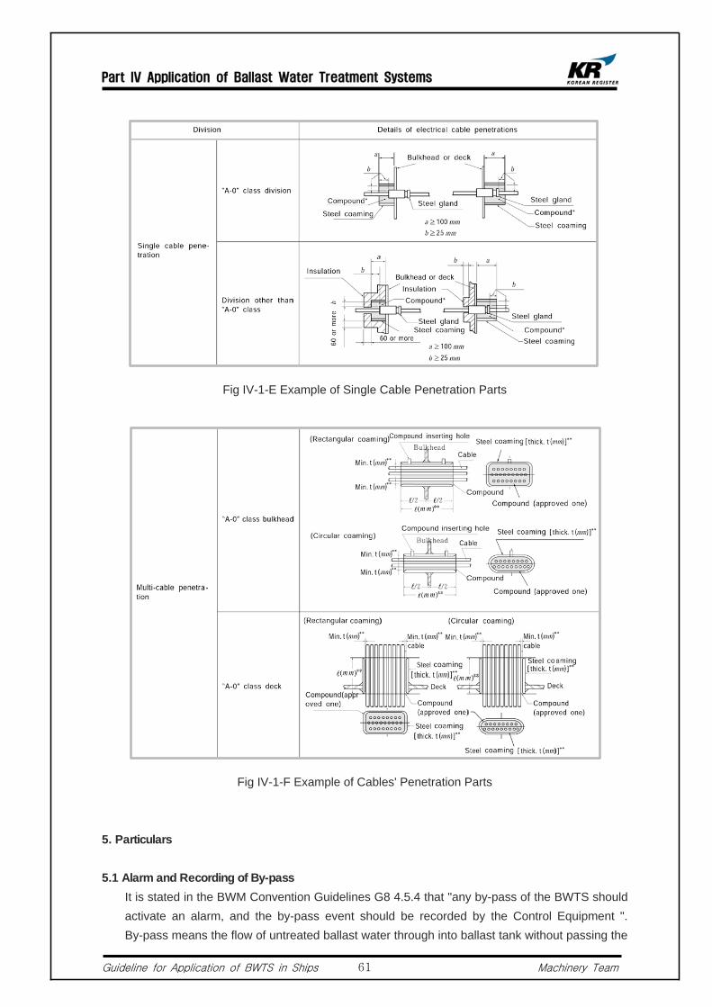
Part IV Application of Ballast Water Treatment Systems
Guideline for Application of BWTS in Ships Machinery Team61
Fig IV-1-E Example of Single Cable Penetration Parts
Fig IV-1-F Example of Cables' Penetration Parts
5. Particulars
5.1 Alarm and Recording of By-pass It is stated in the BWM Convention Guidelines G8 4.5.4 that "any by-pass of the BWTS should
activate an alarm, and the by-pass event should be recorded by the Control Equipment ". By-pass means the flow of untreated ballast water through into ballast tank without passing the

Part IV Application of Ballast Water Treatment Systems
Guideline for Application of BWTS in Ships Machinery Team62
BWTS. Any by-pass of the BWTS should be alarmed and recorded. For the reason, all valves in the by-pass line should be remote-controllable or be equipped with an open/close indicator for automatic detection of the by-pass event by the control equipment.
5.1.1 Installation in Narrow Space In general, most ships are equipped with 2 or more ballast pumps whose discharge outlets
are connected to ballast tanks through 2 main ballast pipelines. However, in small ships, there are cases where the BWTS is connected to only 1 of the main ballast pipe due to limited installation space. In this case, below design consideration should be taken into account. Fig. IV-1-G is an example of BWTS installation where only 1 main ballast pipe is connected to the BWTS.1) All pipes related to the by-pass of BWTS should be removed, or an automatic alarm
system activated in the event of by-pass should be equipped for all valves that may cause by-pass when adjusted. And the by-pass event should be recorded by the control equipment.
2) In most cases, although 2 ballast pumps are used, ballast water is carried through 1 main pipe line. For the reason, design consideration such as over pressure of pipes or excessive flow of ballast water into the BWTS should be taken into account. (In general, piping system is designed for abt. 2~3m/s)
Fig. IV-1-G Piping diagram of water ballast where the BWTS is connected to only 1 main ballast pipe line
5.1.2 Initial operation of BWTS A BWTS that requires by-pass or re-circulation for some periods during its initial ballasting or
de-ballasting is generally designed to have an automatic interlock function to prevent filling/discharging of untreated ballast water flow. This design feature is included in the most
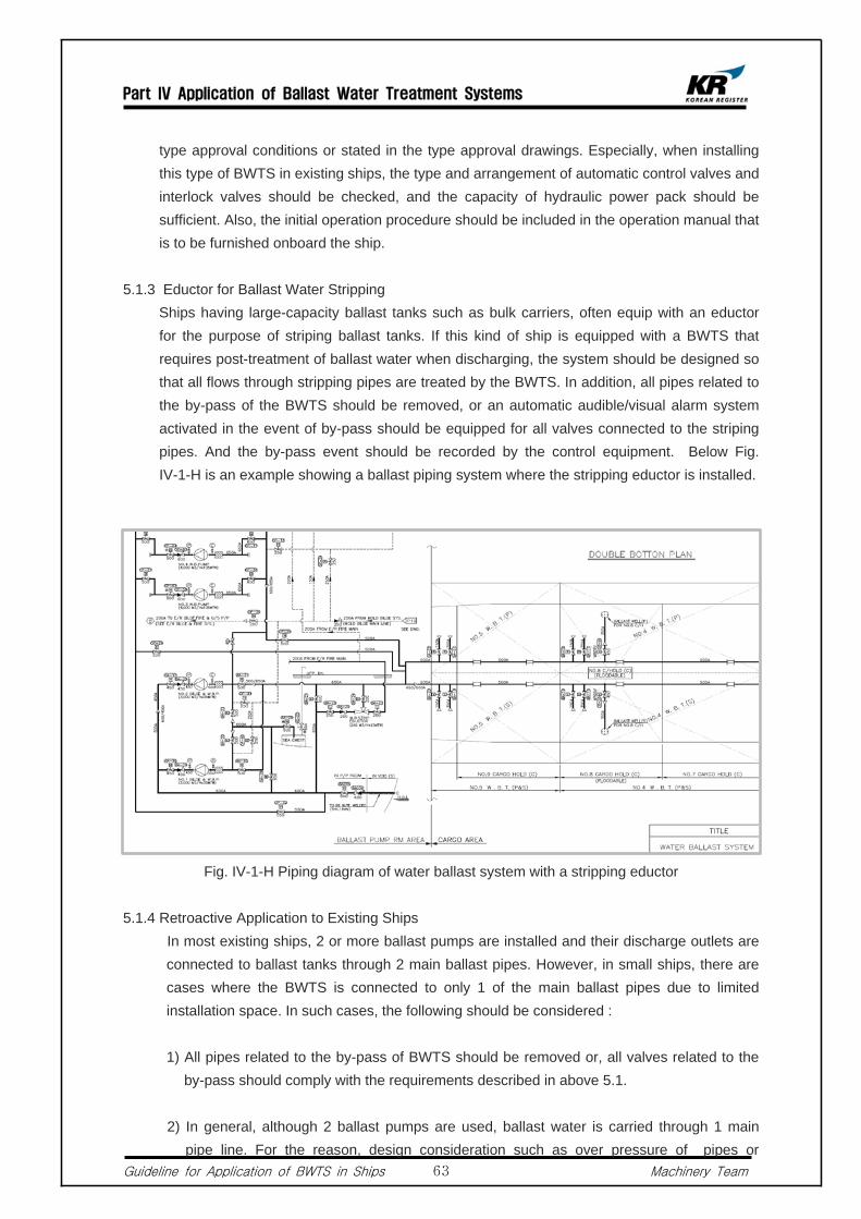
Part IV Application of Ballast Water Treatment Systems
Guideline for Application of BWTS in Ships Machinery Team63
type approval conditions or stated in the type approval drawings. Especially, when installing this type of BWTS in existing ships, the type and arrangement of automatic control valves and interlock valves should be checked, and the capacity of hydraulic power pack should be sufficient. Also, the initial operation procedure should be included in the operation manual that is to be furnished onboard the ship.
5.1.3 Eductor for Ballast Water Stripping Ships having large-capacity ballast tanks such as bulk carriers, often equip with an eductor
for the purpose of striping ballast tanks. If this kind of ship is equipped with a BWTS that requires post-treatment of ballast water when discharging, the system should be designed so that all flows through stripping pipes are treated by the BWTS. In addition, all pipes related to the by-pass of the BWTS should be removed, or an automatic audible/visual alarm system activated in the event of by-pass should be equipped for all valves connected to the striping pipes. And the by-pass event should be recorded by the control equipment. Below Fig. IV-1-H is an example showing a ballast piping system where the stripping eductor is installed.
Fig. IV-1-H Piping diagram of water ballast system with a stripping eductor
5.1.4 Retroactive Application to Existing Ships In most existing ships, 2 or more ballast pumps are installed and their discharge outlets are
connected to ballast tanks through 2 main ballast pipes. However, in small ships, there are cases where the BWTS is connected to only 1 of the main ballast pipes due to limited installation space. In such cases, the following should be considered :
1) All pipes related to the by-pass of BWTS should be removed or, all valves related to the by-pass should comply with the requirements described in above 5.1.
2) In general, although 2 ballast pumps are used, ballast water is carried through 1 main pipe line. For the reason, design consideration such as over pressure of pipes or

Part IV Application of Ballast Water Treatment Systems
Guideline for Application of BWTS in Ships Machinery Team64
excessive flow of ballast water into the BWTS should be taken into account.
5.2 Filling and Discharging by Gravity Ships having a sea chest inside the ballast tank for filling & discharging of ballast water by
gravity, such as large bulk carriers, are required to have double stop-valves connected to the sea chest and the valves should be controllable from a freeboard deck. Below Fig. IV-1-I and IV-1-J are examples of a ship where filling/discharing ballast water is carrying out by gravity.
5.2.1 A BWTS that Treats during Ballast Intake Only1) Ships equipped with a BWTS that treats ballast water during filling process only are
required to close all valves that are attached to the sea chests when filling ballast water into ballast tanks. Also, the valves should comply with the requirements of above 5.1. as by-pass may occur by adjusting the valves.
2) Discharging may be carried out by means of gravity.
5.2.2 A BWTS Having an Additional Treatment Stage During De-ballasting1) Ships equipped with a BWTS that treats ballast water not only during ballast intake
but also during ballast discharge are required to close the valves attached to the sea chests while filling and discharging ballast water. Also, the valves should comply with the requirements of above 5.1. as by-pass may occur by adjusting the valves.
Fig. IV-1-I Filling and Discharging Ballast Water by Gravity

Part IV Application of Ballast Water Treatment Systems
Guideline for Application of BWTS in Ships Machinery Team65
Fig. IV-1-J Filling and Discharging Ballast Water by Gravity
5.3 Ballast Water Discharge by Gravity
5.3.1 A BWTS that Treats during Ballast Intake Only1) If ships equipped with a BWTS that treats during ballast intake only, such as bulk
carriers having a Top Side B.W. Tanks, ballast water discharge may be carried out by gravity.
2) There should be no ingress of untreated ballast water into ballast tanks when during ballast intake. For the reason, check valves should be used in the discharge line. If stop valves are used, requirements in above 5.1 should be met since by pass may occur by adjusting the stop valves.
5.3.2 A BWTS having an additional treatment stage during de-ballasting1) Ships equipped with a BWTS having an additional treatment stage during
de-ballasting are required to close the valves that are attached to the sea chests at all times. Also, since by-pass may occur by adjusting the valves, the requirements in above 5.1 should be complied with.
2) Above 1) should be considered, in particular, if an overflow pipe for ballast exchange is installed in an existing ship for the purpose of complying with the BWM Convention D1 (Ballast Water Exchange Method).
5.4 Cargo Holds Used as Ballast Tanks in Case of Emergency In bulk carriers, there are cases where pipes are installed for the filling of ballast water into
cargo holds for the trimming of draft or maintaining stability in heavy weather. In such cases, the following should be considered.
5.4.1 Ships equipped with a BWTS requiring additional treatment process during ballast discharge must additionally treat the ballast water during ballast discharge.
5.4.2 Due consideration should be given to the arrangement of BWTS whose performance may be affected by sediments or remnants in cargo holds.

Part IV Application of Ballast Water Treatment Systems
Guideline for Application of BWTS in Ships Machinery Team66
5.4.3 For a BWTS using inert gas, due consideration should be given to maintaining an inerting concentration when filling inert gas into the ballast tanks.
5.5 When Using a Ballast Pump for Other Purposes For ships whose fire pump also serves as the ballast pump, if the BWTS is of
remote-controllable type, the in / outlet valves of the fire pump should be remote-controllable. The same should be applied when a bilge pump serves as the ballast pump.
5.6 For Ships Having a KR Class Notation of UMA or Above Ships registered to this Society and having a Class Notation of UMA or above (UMA, UMA1,
UMA2, UMA3) are required to equip with remote-controllable fire pumps according to Pt 9, Ch 3 of the KR-Rules for the Classification of Steel Ships (hereinafter the KR-Rules). Hence, those using fire pumps also for ballasting should take above into account.
5.7 For Ships Having a KR Class Notation UMA or Above Ships registered to this Society and having a Class Notation of UMA1 or above (UMA, UMA1,
UMA2, UMA3) are, according to the KR-Rules Pt 9, Ch 3, 502.1, required to equip with a system that should control ballasting remotely. Hence, for ships with UMA1 or above and having a BWTS installed onboard, all valves related to filling/discharging of ballast water or operation of the BWTS should be of remote controllable type.
5.8 Passenger Ships Engaged on International Voyage The engine room of passenger ships engaged on international voyages is divided into several
sections such as; main engine room, aux. room, pump room, etc. Also, in general, these kinds of ships are designed to use fire or bilge pumps for ballasting and hence required to meet the followings. Fig. IV-1-K is an example of BWTS installation in a passenger ship.
5.8.1 There are cases where the fire pumps or bilge pumps that serve as ballast pumps are scattered in various sections of the engine room. For the reason, the locations or sections in which the BWTS is to be installed should be carefully reviewed in advance. Where all components of the BWTS are remote controllable, please refer to above 5.5.
5.8.2 In case where the fire pumps serves as ballast pumps, refer to above 5.5 and 5.6. Also, if fire pumps that are required to start automatically are commonly used for ballasting, the system should be designed to supply fire-extinguishing water immediately by automatic starting when necessary.
5.8.3 In case where a bilge pump serves as a ballast pump, please refer to above 5.1 and 5.5. Also, due consideration should be given to valve's remote control system because there are cases where the valves for bilge pipe or bilge pump are required to be remote-controllable in case of water ingress or etc.
5.8.4 An inlet pipe of the fire pump or a bilge pump, when installed in a separate area, is often led to a separate sea chest. In this case, the system should be designed such that an alarm
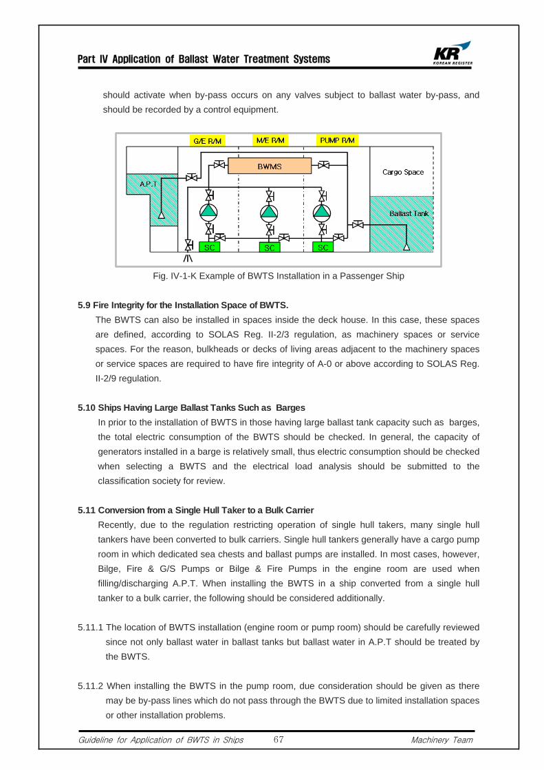
Part IV Application of Ballast Water Treatment Systems
Guideline for Application of BWTS in Ships Machinery Team67
should activate when by-pass occurs on any valves subject to ballast water by-pass, and should be recorded by a control equipment.
Fig. IV-1-K Example of BWTS Installation in a Passenger Ship
5.9 Fire Integrity for the Installation Space of BWTS. The BWTS can also be installed in spaces inside the deck house. In this case, these spaces
are defined, according to SOLAS Reg. II-2/3 regulation, as machinery spaces or service spaces. For the reason, bulkheads or decks of living areas adjacent to the machinery spaces or service spaces are required to have fire integrity of A-0 or above according to SOLAS Reg. II-2/9 regulation.
5.10 Ships Having Large Ballast Tanks Such as Barges In prior to the installation of BWTS in those having large ballast tank capacity such as barges,
the total electric consumption of the BWTS should be checked. In general, the capacity of generators installed in a barge is relatively small, thus electric consumption should be checked when selecting a BWTS and the electrical load analysis should be submitted to the classification society for review.
5.11 Conversion from a Single Hull Taker to a Bulk Carrier Recently, due to the regulation restricting operation of single hull takers, many single hull
tankers have been converted to bulk carriers. Single hull tankers generally have a cargo pump room in which dedicated sea chests and ballast pumps are installed. In most cases, however, Bilge, Fire & G/S Pumps or Bilge & Fire Pumps in the engine room are used when filling/discharging A.P.T. When installing the BWTS in a ship converted from a single hull tanker to a bulk carrier, the following should be considered additionally.
5.11.1 The location of BWTS installation (engine room or pump room) should be carefully reviewed since not only ballast water in ballast tanks but ballast water in A.P.T should be treated by the BWTS.
5.11.2 When installing the BWTS in the pump room, due consideration should be given as there may be by-pass lines which do not pass through the BWTS due to limited installation spaces or other installation problems.

Part IV Application of Ballast Water Treatment Systems
Guideline for Application of BWTS in Ships Machinery Team68
5.11.3 If an existing turbine-driven cargo pump is served as a ballast pump, the head of the turbine-driven cargo pump, which is generally very high, should be take into consideration when installing the BWTS.
5.11.4 For a BWTS that also treats ballast water during ballast discharge and using a Ballast Stripping Pump or an Eductor, the location of its components should be carefully determined during design stage. In this case, above 5.1.3 should be referred to.
5.12 Modification of Ballast Tank According to the BWM Convention Annex A-1, Reg.5, an existing ship carrying out major
conversion is considered as a new ship. "Major conversion" means the conversion of a ship :
- which changes its ballast water carrying capacity by 15% or greater, or - which changes the ship type, or - which, approved by the Administration, is projected to prolong its life by ten years or more,
or - which results in modification to its ballast water system other than replacement of
components
5.13 Fresh Water Tank When a fresh water tank is served as a ballast tank, chemicals contained in the fresh water
may potentially be discharged. In this regards, the application of the BWM Convention to portable water is under discussion at IMO.
5.14 Electric Consumption and Composition of Electric Circuit Electric load analysis should be carried out and the result should be submitted to this Society
to make sure that the electric power installed on-board is sufficient to cover the increased electric consumption. Also, electrical equipment of the BWTS should be protected from overloading or short-circuit.
5.15 Special Considerations for Electrolysis Type BWTS
5.15.1 Electric Pressure Drop1) In case of an electrolysis type BWTS, DC 36V converted from AC 440V (or 220V)
by means of a rectifier is supplied to the BWTS. In a such case, a large quantity of electric current flows in the circuit.
2) Therefore, the longer the distance of power transmission, the bigger the electric pressure drops. For the reason, the length of cables should be within the supplier's recommendation.
5.15.2 Construction of Cable Runs using Bus-bars1) The electrolysis type BWTS transmits a large amount of electric current that when
the capacity of BWTS increases, the size and number of cables also increase. For

Part IV Application of Ballast Water Treatment Systems
Guideline for Application of BWTS in Ships Machinery Team69
the reason, the Bus-bars are often used to reduce the size of electric installation.2) Installation of Bus-bars in weather deck or dangerous areas should be avoided. If
installed in dangerous spaces, the Bus-bars should be of explosion proof type. Specially, when the Bus-bars penetrates a boundary between a safe area and a dangerous area, explosion and sealing requirements for the penetration parts should be met. Also, the methods of on-board installation and penetration piece installation should be approved by this Society.
5.16 Control, Monitoring and Alarm of BWTS The BWM Convention Guidance 8, Chapter4, describes the requirements of control
equipment, monitoring and alarm equipment.
5.16.1 Control, Monitoring and Alarm of BWTS1) The amount of injection or the injection level of BWTS that is required for the
treatment of ballast water should be controlled automatically. The control equipment should be capable of continuous self-monitoring during operation, and operation related items should be automatically monitored and controled.
2) Malfunction or errors occurring in the system should be monitored. And if these kinds of problems affect operation of the BWTS, audible/visual alarm should be activated in all areas in which the ballast water treatment process is regulated.
5.16.2 Operation and Control1) Operation and control of BWTS should be simple and effective, and all control
should be remote controllable, as far as practicable. However, this does not necessarily mean the automation of all valves related to the BWTS, but easy and effective manual operation is acceptable, except those that may cause BWTS's malfunction. In such a case, it is recommended that guidelines for the handling procedure of manual valves when filling/discharging ballast water and piping diagrams indicating related valves should be posted in all control areas.
2) Ships registered to this Society and having a notation of UMA1 or above are required that all valves related to the operation of BWTS and ballast pumps should be remote controllable, and such a system should be interconnected with the existing remote control devices of the ballast pumps for automatic control.
5.16.3 By-pass and Override 1) Ships equipped with a BWTS should install a means of by-pass or override for the
protection of the ships or their crews in case of emergency. Also, in the event of by-pass, audible/visual alarm should be automatically activated by the monitoring system and the by-pass events should be recorded in the control system.
2) In case of existing ships, a BWTS is generally to be installed in one side of the ballast lines. For the reason, the usage of other ballast lines should be monitored. In relation to this, suppliers should submit the list of all possible by-pass scenarios considering the ships's ballast piping arrangement to this Society for review.
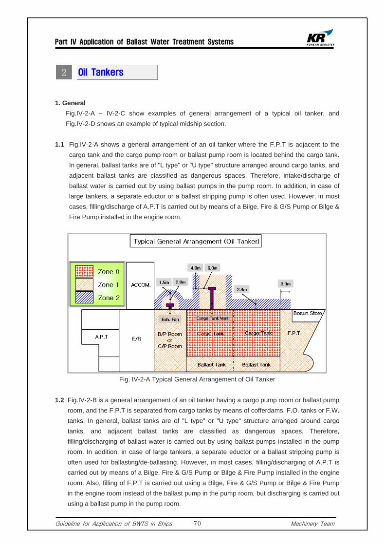
Part IV Application of Ballast Water Treatment Systems
Guideline for Application of BWTS in Ships Machinery Team70
Oil Tankers
1. General Fig.IV-2-A ~ IV-2-C show examples of general arrangement of a typical oil tanker, and
Fig.IV-2-D shows an example of typical midship section.
1.1 Fig.IV-2-A shows a general arrangement of an oil tanker where the F.P.T is adjacent to the cargo tank and the cargo pump room or ballast pump room is located behind the cargo tank. In general, ballast tanks are of "L type" or "U type" structure arranged around cargo tanks, and adjacent ballast tanks are classified as dangerous spaces. Therefore, intake/discharge of ballast water is carried out by using ballast pumps in the pump room. In addition, in case of large tankers, a separate eductor or a ballast stripping pump is often used. However, in most cases, filling/discharge of A.P.T is carried out by means of a Bilge, Fire & G/S Pump or Bilge & Fire Pump installed in the engine room.
Fig. IV-2-A Typical General Arrangement of Oil Tanker
1.2 Fig.IV-2-B is a general arrangement of an oil tanker having a cargo pump room or ballast pump room, and the F.P.T is separated from cargo tanks by means of cofferdams, F.O. tanks or F.W. tanks. In general, ballast tanks are of "L type" or "U type" structure arranged around cargo tanks, and adjacent ballast tanks are classified as dangerous spaces. Therefore, filling/discharging of ballast water is carried out by using ballast pumps installed in the pump room. In addition, in case of large tankers, a separate eductor or a ballast stripping pump is often used for ballasting/de-ballasting. However, in most cases, filling/discharging of A.P.T is carried out by means of a Bilge, Fire & G/S Pump or Bilge & Fire Pump installed in the engine room. Also, filling of F.P.T is carried out using a Bilge, Fire & G/S Pump or Bilge & Fire Pump in the engine room instead of the ballast pump in the pump room, but discharging is carried out using a ballast pump in the pump room.

Part IV Application of Ballast Water Treatment Systems
Guideline for Application of BWTS in Ships Machinery Team71
Fig. IV-2-B Typical General Arrangement of an Oil Tanker-1
Fig. IV-2-C Typical General Arrangement of an Oil Tanker-2
1.3 Fig. IV-2-C is an example of an oil tanker not having a cargo pump room or ballast pump room. In general, ballast tanks are of "L type" or "U type" structure arranged around cargo tanks, and adjacent ballast tanks are classified as dangerous spaces. In this case, a submersible type pump is generally used for ballasting, and ballast pumps and sea chests are arranged inside the ballast tanks. Also, valves installed in the ballast piping system are of remote controllable type. Therefore, filling and discharging of ballast water is carried out by means of submersible pumps. However, there are cases where a Bilge, Fire & G/S Pump or Bilge & Fire Pump installed in the engine room is used for filling and discharging of A.P.T. Also, filling of F.P.T is carried out using a Bilge, Fire & G/S Pump or Bilge & Fire Pump in the engine room instead of ballast pumps in the pump room. But discharging is generally carried out using ballast pumps in the pump room.

Part IV Application of Ballast Water Treatment Systems
Guideline for Application of BWTS in Ships Machinery Team72
Fig. IV-2-D Typical Midship Section of an Oil Tanker
1.4 Fig IV-2-E is an example of general arrangement and midship section of a FA Tanker designed for carrying cargo oil having a flash point above 60℃. In this case, ballast tanks are typically of "L type" or "U type" structure arranged around cargo tanks. According to IEC 60092-502 Reg. 4.3, adjacent ballast tanks are classified as safe spaces except when carrying cargoes having a flash point below 15℃. Filling/discharging of each ballast tank is carried out using a Bilge, Fire & G/S Pump or Bilge & Fire Pump installed in the engine room or ballast pumps installed in the ballast pump room.
Fig. IV-2-E A Typical General Arrangement and Midship Section of a FA Oil Tanker
2. Related Regulations
2.1 KR-Rules Part7, Chapter1 1003.2 Ballast tanks adjacent to cargo oil tanks should comply with followings;
2.1.1 The requirements in this Paragraph are also applied to ballast tanks used as cofferdams at the fore and after ends of cargo oil tanks.

Part IV Application of Ballast Water Treatment Systems
Guideline for Application of BWTS in Ships Machinery Team73
2.1.2 Ballast pipes in ballast tanks adjacent to cargo oil tanks are to be separated from other pipes and are not to be led to the engine room. For this purpose, an exclusive pump for ballasting and de-ballasting these tanks is generally to be provided in the pump room. However, if specially approved by this Society, cargo pumps may be used for the purpose of de-ballasting in case of emergency only. In addition, ballast tanks are classified as a safe area in case that tanks are not adjacent to cargo oil tanks. In this case, other requirements set out by this Society may be applied.
2.1.3 Air pipes of ballast tanks adjacent to cargo oil tanks are to be provided with an easily replaceable flame screen at their outlets.
2.1.4 Sounding pipes of ballast tanks adjacent to cargo oil tanks are to be led above the weather deck, unless otherwise approved by this Society.
2.2 KR Guidance Relating to the Rules for the Classification of Steel Ships (hereinafter the KR-Guidance) Part7, Chapter1 1003.2
In application of the above 2.1 Rules, a ballast piping system for ballast tanks adjacent to cargo oil tanks is to comply with the following requirements:
2.2.1 Ballast tanks defined as being safe are to be ballasted and de-ballasted by pumps which are located in gas safe areas. However, they may be de-ballasted by pumps which are located in dangerous areas, provided that a check valve is fitted on the line for de-ballasting only.
2.2.2 In case where ballast tanks adjacent to cargo oil tanks are intended to be de-ballasted by cargo oil pumps in an emergency, a spool piece(or blank flange) and a screw-down non-return valve are to be provided on each ballast pipe at joints with cargo oil pipes. Further, a warning notice is to be posted stating that spool pieces are to be removed except for emergencies.
2.3 KR-Rules, Part 7, Chapter 1, 1003.3 A fore peak ballast tank ballasted through pipes serving other ballast tanks in cargo areas is to
meet with the following requirements: (Refer to IACS UR F44)
2.3.1 Openings of vent pies are to be located on open deck separated from ignition sources by the distance required by IEC 60092-502.
2.3.2 Means are to be provided on open deck to allow measurement of flammable gas concentrations in a fore peak tank by a suitable portable instrument.
2.3.3 The sounding arrangement to a fore peak tank is to be direct from open deck.
2.3.4 The access to a fore peak tank is to be direct from open deck. Alternatively, indirect access from open deck to a fore peak tank through an enclosed space may be accepted provided that :

Part IV Application of Ballast Water Treatment Systems
Guideline for Application of BWTS in Ships Machinery Team74
1) In case that the enclosed space is separated from cargo tanks by cofferdams, the access is to be through a gas tight bolted manhole located in enclosed spaces and a warning sign is to be provided at the manhole stating that the fore peak tank may only be opened after;
a. it has been proven to be gas free; or b. any electrical equipment which is not certified safe in the enclosed space is isolated. 2) In case that an enclosed space has a common boundary with cargo tanks and is therefore
hazardous, the enclosed space is to be well ventilated.
2.4 KR-Guidance, Part7, Chapter1, 1003.2 In application of the above 2.3 requirements, ballast piping system for ballast tanks adjacent to
cargo oil tanks is to be dealt with under the following requirements:
2.4.1 Ballast tanks defined as being safe are to be ballasted and de-ballasted by pumps which are located in gas safe areas. However, they may be de-ballasted by pumps which are located in dangerous area, provided that a check valve fitted on the line for only de-ballasting.
2.4.2 In case where ballast tanks adjacent to cargo oil tanks are intended to be de-ballasted by cargo oil pumps in an emergency, a spool piece(or blank flange) and a screw-down non-return valve are to be provided on each ballast pipe at joints with cargo oil pipes. Further, a warning notice is to be posted stating that spool pieces are to be removed except for emergencies.
3. Protection for Dangerous Area and Electrical Equipment
3.1 Dangerous spaces in oil tankers carrying cargo oil having a flash point of 60℃ or below For oil takers carrying cargo oil having a flash point of 60℃ or below, dangerous space is
classified under space 0, space 1, and space 2 according to the probability of existence of flammable oil mist and its dangerousness, where each class demands different requirements for electrical installation. Ballast tanks related to the BWTS and a cargo pump room where the BWTS is likely to be installed are classified as space 1. And spaces up to 2.4m above upper deck are classified as space 2. Therefore, when installing electrical equipment in the above-mentioned dangerous spaces, special consideration for explosion-proof requirements should be taken into account. Fig. IV-2-A~D are examples of typical dangerous spaces in FB tankers. For more information regarding dangerous spaces and protection of electrical equipment, please refer to Appendix "Hazardous Areas and Requirements for Electrical Installation in Each Ship Type", chapter 2.
3.2 Dangerous Spaces in Oil Tankers Carrying Cargo Having a Flash Point Above 60℃. In tankers carrying cargo oil having a flash point above 60℃, cargo tanks, cargo tank
ventilation pipes and inside of cargo pipes are, according to IEC 60092-502 Reg.4.3, classified as dangerous space 2. Fig. IV-2-E shows examples of areas which are generally classified as dangerous spaces in FA tankers.
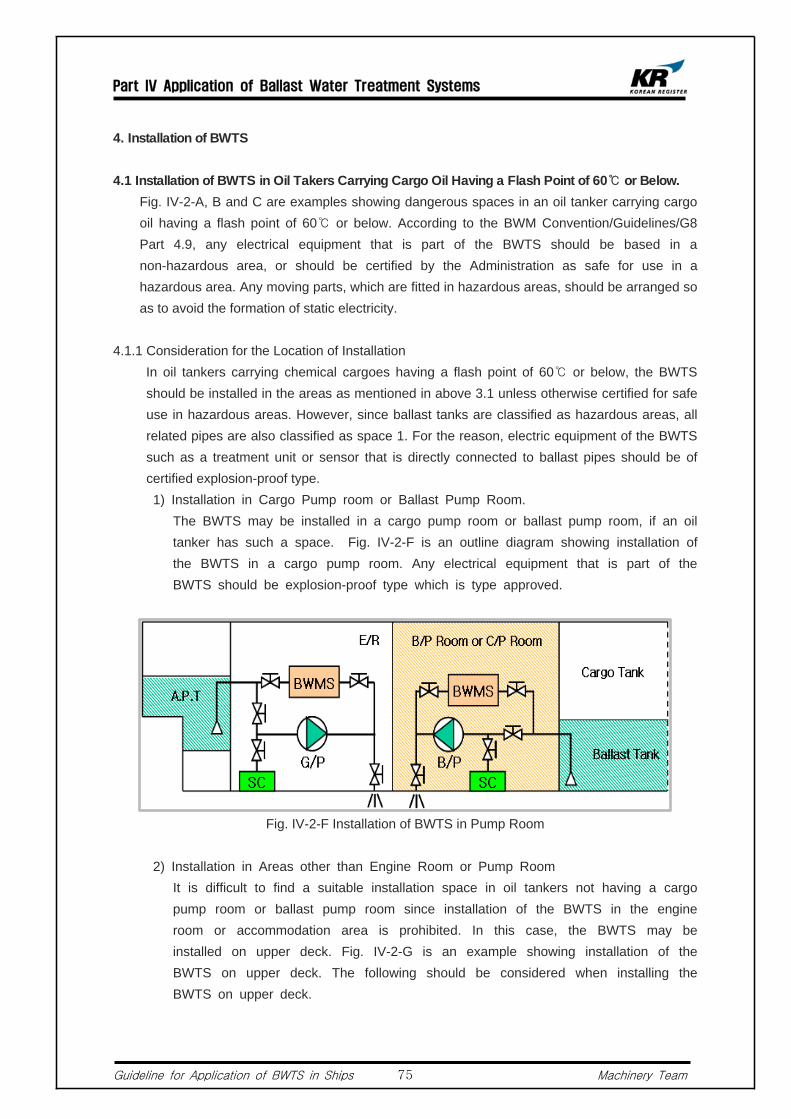
Part IV Application of Ballast Water Treatment Systems
Guideline for Application of BWTS in Ships Machinery Team75
4. Installation of BWTS
4.1 Installation of BWTS in Oil Takers Carrying Cargo Oil Having a Flash Point of 60℃ or Below. Fig. IV-2-A, B and C are examples showing dangerous spaces in an oil tanker carrying cargo
oil having a flash point of 60℃ or below. According to the BWM Convention/Guidelines/G8 Part 4.9, any electrical equipment that is part of the BWTS should be based in a non-hazardous area, or should be certified by the Administration as safe for use in a hazardous area. Any moving parts, which are fitted in hazardous areas, should be arranged so as to avoid the formation of static electricity.
4.1.1 Consideration for the Location of Installation In oil tankers carrying chemical cargoes having a flash point of 60℃ or below, the BWTS
should be installed in the areas as mentioned in above 3.1 unless otherwise certified for safe use in hazardous areas. However, since ballast tanks are classified as hazardous areas, all related pipes are also classified as space 1. For the reason, electric equipment of the BWTS such as a treatment unit or sensor that is directly connected to ballast pipes should be of certified explosion-proof type.
1) Installation in Cargo Pump room or Ballast Pump Room. The BWTS may be installed in a cargo pump room or ballast pump room, if an oil
tanker has such a space. Fig. IV-2-F is an outline diagram showing installation of the BWTS in a cargo pump room. Any electrical equipment that is part of the BWTS should be explosion-proof type which is type approved.
Fig. IV-2-F Installation of BWTS in Pump Room
2) Installation in Areas other than Engine Room or Pump Room It is difficult to find a suitable installation space in oil tankers not having a cargo
pump room or ballast pump room since installation of the BWTS in the engine room or accommodation area is prohibited. In this case, the BWTS may be installed on upper deck. Fig. IV-2-G is an example showing installation of the BWTS on upper deck. The following should be considered when installing the BWTS on upper deck.
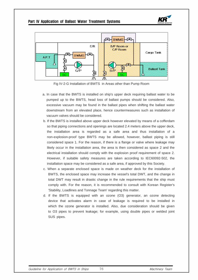
Part IV Application of Ballast Water Treatment Systems
Guideline for Application of BWTS in Ships Machinery Team76
Fig IV-2-G Installation of BWTS in Areas other than Pump Room
a. In case that the BWTS is installed on ship's upper deck requiring ballast water to be pumped up to the BWTS, head loss of ballast pumps should be considered. Also, excessive vacuum may be found in the ballast pipes when shifting the ballast water downstream from an elevated place, hence countermeasures such as installation of vacuum valves should be considered.
b. If the BWTS is installed above upper deck however elevated by means of a cofferdam so that piping connections and openings are located 2.4 meters above the upper deck, the installation area is regarded as a safe area and thus installation of a non-explosion-proof type BWTS may be allowed, however, ballast piping is still considered space 1. For the reason, if there is a flange or valve where leakage may likely occur in the installation area, the area is then considered as space 2 and the electrical installation should comply with the explosion proof requirement of space 2. However, if suitable safety measures are taken according to IEC60092-502, the installation space may be considered as a safe area, if approved by this Society.
c. When a separate enclosed space is made on weather deck for the installation of BWTS, the enclosed space may increase the vessel's total DWT, and the change in total DWT may result in drastic change in the rule requirements that the ship must comply with. For the reason, it is recommended to consult with Korean Register's 'Stability, Loadlines and Tonnage Team' regarding this matter.
d. If the BWTS is equipped with an ozone (O3) generator, an ozone detecting device that activates alarm in case of leakage is required to be installed in which the ozone generator is installed. Also, due consideration should be given to O3 pipes to prevent leakage; for example, using double pipes or welded joint SUS pipes.
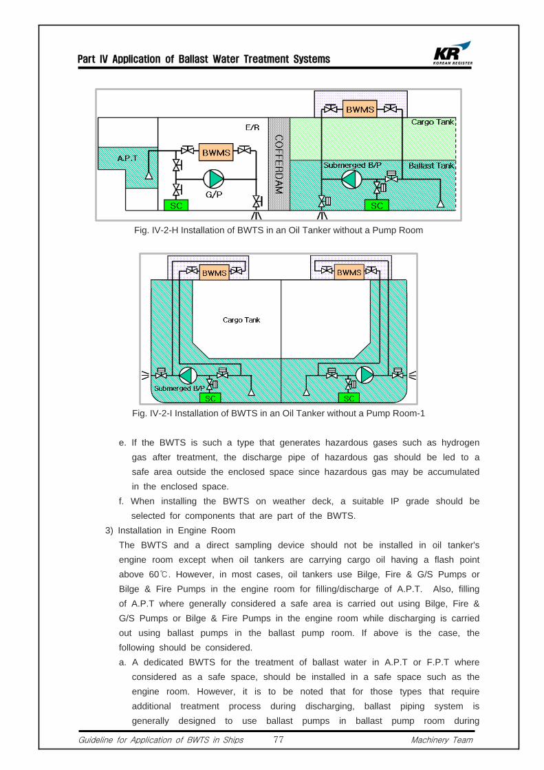
Part IV Application of Ballast Water Treatment Systems
Guideline for Application of BWTS in Ships Machinery Team77
Fig. IV-2-H Installation of BWTS in an Oil Tanker without a Pump Room
Fig. IV-2-I Installation of BWTS in an Oil Tanker without a Pump Room-1
e. If the BWTS is such a type that generates hazardous gases such as hydrogen gas after treatment, the discharge pipe of hazardous gas should be led to a safe area outside the enclosed space since hazardous gas may be accumulated in the enclosed space.
f. When installing the BWTS on weather deck, a suitable IP grade should be selected for components that are part of the BWTS.
3) Installation in Engine Room The BWTS and a direct sampling device should not be installed in oil tanker's
engine room except when oil tankers are carrying cargo oil having a flash point above 60℃. However, in most cases, oil tankers use Bilge, Fire & G/S Pumps or Bilge & Fire Pumps in the engine room for filling/discharge of A.P.T. Also, filling of A.P.T where generally considered a safe area is carried out using Bilge, Fire & G/S Pumps or Bilge & Fire Pumps in the engine room while discharging is carried out using ballast pumps in the ballast pump room. If above is the case, the following should be considered.
a. A dedicated BWTS for the treatment of ballast water in A.P.T or F.P.T where considered as a safe space, should be installed in a safe space such as the engine room. However, it is to be noted that for those types that require additional treatment process during discharging, ballast piping system is generally designed to use ballast pumps in ballast pump room during

Part IV Application of Ballast Water Treatment Systems
Guideline for Application of BWTS in Ships Machinery Team78
discharging and thus use of the BWTS in the engine room may not be possible.
b. If the BWTS is equipped with an ozone (O3) generator, an ozone detecting device that activates alarm in case of leakage is required to be installed in which the ozone generator is installed. Also, due consideration should be given to O3 pipes to prevent leakage; for example, using double pipes or welded joint SUS pipes.
c. If the BWTS is such a type that generates hazardous gas such as hydrogen gas after treatment, the discharge pipe of the hazardous gas should be led to a safe area outside the enclosed space since the hazardous gas may be accumulated in the enclosed space.
d. In case that some components of the BWTS installed in the engine room inject treatment materials to other components of the BWTS in ballast pump room, the following should be satisfied.
Should only be used during ballast intake Should not penetrate a bulkhead between an engine room and pump room
but penetrate through a deck. Pipes with small diameter should be used. To prevent a back flow in injection pipes, suitable countermeasures (2 sets
of check valves connected in series) should be installed in cargo areas. Fig. IV-2-J is an example showing blocking up of back flow applied in a similar piping system.
Fig. IV-2-J Example of Blocking Up Method
4.1.2 Electrical Installation for Ballast Sampling Type BWTS Those sampling directly from ballast pipes such as a TRO(Total Residual Oxidant)
Sensor Unit or a Gas Sensor Unit should be explosion-proof type which is type approved even when installed outside the dangerous area. If installed in a safe space,

Part IV Application of Ballast Water Treatment Systems
Guideline for Application of BWTS in Ships Machinery Team79
electrical equipment should be of appropriate type for the area.
4.1.2 Special Considerations for Electrolysis Type BWTS 1) Voltage Drop over Cable Runs In case of an electrolysis type BWTS, AC 440V (or 220V) is converted into DC
36V by a rectifier so that a large amount of electric current flows in the circuit, hence the distance of power transmission may be a cause of voltage drop. Therefore, for safe operation, the length of cables should be within manufacturer's recommendation.
2) Composition of Cable Runs using Bus-bars The electrolysis type BWTS, when its capacity become larger, the required electric
current transmission also become larger resulting in increase in size and number of cables. For the reason, a Bus-bar is often used to reduce the installation space. In this case, the Bus-bars should be of KR type-approved and be installed in a trunk whose protection grade is IP54 or above. Installation in dangerous spaces or on weather deck should be avoided. If installed in dangerous spaces, the Bus-bar should be explosion-protection type. Particularly, when penetrating a boundary between a safe area and a dangerous space, fire protection and sealing requirements for penetrating pieces should be complied with. Also, on-board installation methods and the details of penetration parts should be approved by this Society.
4.1.4 General Requirements for Electrical Equipment in Oil Tanker's Dangerous Spaces. The following should be complied with according to KR-Rules Part 7 Chapter 1/11. 1) Explosion Protection Level The explosion protection level of electric equipment such as ballast water treatment
equipment, sensors and automatic control valves installed in ballast piping are to be IIB T4 or above.
2) Hull Return System of Distribution Electrical equipment installed in oil tankers is not to earth or use hull return
system unless otherwise listed in KR's Rules for the Classification of Steel Ships Part7, Chapter1 1101.3.
3) Isolation Switch Each distribution circuit for electrical equipment installed in dangerous spaces
should be provided with multi-pole linked isolation switches installed in a safe space. In addition, the isolation switches are to be clearly labelled to identify the electrical equipment to be connected with, and further effective means are to be provided to avert danger due to unauthorized operation of isolation switches.
4) Monitoring of Insulation Level Excluding intrinsically safe circuits, feeders and distribution circuits to be connected
to the electrical equipments in dangerous spaces or to run through dangerous spaces are to be provided with such devices that keep monitoring the insulation levels and will give an alarm in case of abnormally low level.
5) Cable

Part IV Application of Ballast Water Treatment Systems
Guideline for Application of BWTS in Ships Machinery Team80
a. Cables are to be of armored Non-metallic Sheath Type. b. Cables are to be installed as close to the hull centre line as practicable. c. Cables are sufficiently distant from decks, bulkheads, tanks, and various kinds of
pipes. d. Cables installed on the fore and aft gangways and the decks are to be
protected against mechanical damage. Further, the cables and their supports are to be fitted in such a manner as to withstand expansion and contraction and other effects of the hull structure.
e. The penetration part of cables or cable pipes through decks and bulkheads of dangerous spaces is to be constructed so as to maintain gas-tightness and liquid-tightness as the case may require.
f. When mineral insulated cables are used, special precaution is to be taken to ensure sound terminations.
g. All metallic protective coverings of power and lighting cables passing through dangerous spaces, or connected to equipment in such spaces, are to be earthed at least at each end.
4.1.5 Examples of Installation Fig. IV-2-J and K are examples showing the installation of BWTS in a dangerous
space of an oil tanker carrying cargo oil having a flash point below 60℃. In the figure, the ballast treatment equipment and sensors installed in ballast pipes inside the red box in Fig IV-2-K and L are explosion-proof type and other non-explosion protected equipment is arranged outside dangerous spaces. In addition, sensors directly connected to ballast pipes such as FMU (FLOW METER UNIT) are to be of explosion-proof type.
Fig.IV-2-K Electrolysis Type BWTS

Part IV Application of Ballast Water Treatment Systems
Guideline for Application of BWTS in Ships Machinery Team81
Fig. IV-2-L Ozone Type BWTS
4.2 Tankers Carrying Cargo Oil having a Flash Point Above 60℃
If installed outside the dangerous spaces mentioned in 3.2, explosion protection is not required since ballast tanks are not considered as dangerous spaces.
4.3 Measures for Pipes and Penetration Parts of Cables Penetrating parts of pipes and cables for the BWTS, when penetrating a bulkhead or
a deck, are required to be of the same water-tight or fire protection level to that of the penetrated bulk head or the deck. Additionally, when a cable is penetrating a boundary between a safe space and a dangerous space, gas-tight requirements should be complied with. For more details about penetrating parts, please refer to KR-Rules Part 8, Annex 8-2 "Penetrations through Divisions".
5. Particulars
5.1 By-pass Alarm and Recording for BWTS It is stated in the BWM Convention Guidelines G8 4.5.4 that any by-pass of the
BWTS should activate an alarm, and the by-pass event should be recorded by the control equipment. "by-pass" means filling/discharging of untreated ballast water in/from ballast tanks without passing the BWTS. Therefore, all valves related to the by-pass event should be of remote controllable type or be equipped with an open/close indicator so that automatic detection and alarm are enabled from BWTS's control device.
5.1.1 Installation in Narrow Space In general, 2 or more ballast pumps are installed onboard ships, and in most of the

Part IV Application of Ballast Water Treatment Systems
Guideline for Application of BWTS in Ships Machinery Team82
cases, ballast water is filled/discharged in/out of ballast tanks via 2 main ballast pipes on the ballast pump's discharge side. However in small ships, there are cases where the BWTS is installed on only one side of the ballast pipes due to limited installation space. In this case, the below design considerations should be taken into account. Fig. IV-2-M is an example where the BWTS is installed on only one side of main ballast pipes.
1) All pipes related to the by-pass of BWTS should be removed, or an automatic alarm system activated in the event of by-pass should be equipped for all valves that may cause by-pass when adjusted. And the by-pass event should be recorded by control equipment.
2) In general, although 2 ballast pumps are used, ballast water is carried through a main pipe line. For the reason, design consideration such as over pressure of pipes or excessive flow of ballast water into the BWTS should be given (In general, piping system is designed for abt. 2~3m/s)
Fig. IV-2-M Piping diagram where the BWTS is installed in only one side of the main ballast pipes
5.1.2 Initial Operation of BWTS For a BWTS that requires by-pass or re-circulation for some periods during its initial
operation, valves controling filling and discharging are generally designed to have an automatic interlock function to prevent filling/discharging of untreated ballast water flow. This design feature is included in the most type approval conditions or stated in type approval drawings. Especially, when installing this type of BWTS in existing ships, the type and arrangement of automatic control valves and interlock valves should be checked, and the capacity of hydraulic power pack should be sufficient. Also, initial operation procedure should be included in the BWTS' operation manual that is to be

Part IV Application of Ballast Water Treatment Systems
Guideline for Application of BWTS in Ships Machinery Team83
furnished onboard ships.
5.1.3 Eductor for Ballast Water Stripping Ships having large-capacity ballast tanks such as bulk carriers often equip with an
eductor for the purpose of striping ballast tanks. If this kind of ship is equipped with a BWTS that requires post-treatment of ballast water when discharging, the system should be designed so that all flows through stripping pipes are treated by the BWTS. In addition, all pipes that may enable the by-pass of BWTS should be removed, or an automatic audible/visual alarm system activated in the event of by-pass is to be equipped for all valves connected to the striping pipes. And the by-pass event should be recorded by the control equipment. Fig. IV-2-N is an example showing a ballast piping system where a stripping eductor is installed.
Fig. IV-2-N Ballast Piping System with a Stripping Eductor
5.1.4 Retroactive Application to Existing Ships In most existing ships, 2 or more ballast pumps are installed, and their discharge
outlet are connected to ballast tanks through 2 main ballast pipes. However, in small ships, there are cases where the BWTS is connected to only one of the main ballast pipes due to limited installation space. In such cases, the following should be considered.
1) All pipes related to the by-pass of BWTS should be removed or, all valves related to the by-pass should comply with the requirements described in above 5.1.
2) In general, although 2 ballast pumps are used, ballast water is carried through 1 main pipe line. For the reason, design consideration such as over pressure of pipes or excessive flow of ballast water into the BWTS should be taken into account.
5.2 Filling and Discharging by Gravity Ships having a sea chest inside ballast tanks therefore carrying out filling &

Part IV Application of Ballast Water Treatment Systems
Guideline for Application of BWTS in Ships Machinery Team84
discharging of ballast water by gravity, such as large oil tankers, are required to have double stop-valves connected to the sea chest and the valves should be controllable from freeboard deck. This type of ships can be further categorized into those carrying out ballast water filling by gravity and those carrying out both filling and discharging by gravity. Fig. IV-2-O and IV-2-P are examples of a ship carrying out filling and discharging ballast water by gravity.
5.2.1 A BWTS that Treats During Ballast Water Intake Only 1) Ships equipped with a BWTS that treats ballast water during filling process only
are required to close all valves that are attached to sea chests when filling ballast water into ballast tanks. Also, valves should comply with the requirements of above 5.1. as by-pass may occur at the valves.
2) Discharging may be carried out by means of gravity.
5.2.2 A BWTS Having an Additional Treatment Stage During De-ballasting 1) Ships equipped with a BWTS that treats ballast water not only during ballast intake but
also during ballast discharge are required to close the valves attached to the sea chests while filling and discharging ballast water. Also, the valves should comply with the requirements of above 5.1. as by-pass may occur by adjusting the valves.
Fig. IV-2-O Filling and Discharging by Gravity

Part IV Application of Ballast Water Treatment Systems
Guideline for Application of BWTS in Ships Machinery Team85
Fig. IV-2-P Filling and Discharging by Gravity
5.3 Ballast Water Discharge by Gravity
5.3.1 A BWTS that Treats During De-ballasting Only 1) Ships designed to discharge ballast water by gravity, if a BWTS that treats ballast
water during filling only is installed, may discharge ballast water by gravity. 2) There should be no ingress of untreated ballast water into ballast tanks during
ballast intake. For the reason, check valves should be used in the discharge section. If stop valves are used, requirements in above 5.1 should be met since by-pass may occur at the stop valve.
5.3.2 A BWTS having an Additional Treatment Stage During De-ballasting 1) Ships equipped with a BWTS having an additional treatment stage during
de-ballasting are required to close valves that are attached to sea chests at all times. Also, the valves should comply with the requirements of above 5.1. as by-pass may occur at the valves.
2) Above 1) should be considered, in particular, if an overflow pipe for the ballast exchange is installed in an existing ship for the purpose of complying with the BWM Convention D1 (Ballast Water Exchange Method).
5.4 Cargo Holds Used as Ballast Tanks Generally, oil tankers are capable of filling ballast water into cargo holds in case of
heavy weather or emergency. In case of VLCC, there are cases where piping which is normally closed by a blind flange is installed to enable direct suction of ballast water by means of cargo pumps from a sea chest in the cargo pump room. Also, in most oil tankers, a piping system is designed to enable pumping of ballast water from cargo holds not by ballast pumps but by cargo pumps, which is then discharged overboard via an ODME. For the reason, where the BWTS that requires post treatment during discharging is installed onboard this type of ships, the following should be considered.

Part IV Application of Ballast Water Treatment Systems
Guideline for Application of BWTS in Ships Machinery Team86
5.4.1 Cargo tank piping should be designed so that discharging is possible.
5.4.2 There may be oily impurities in cargo tanks which may reduce the performance of BWTS during discharging. Therefore, due consideration should be given when choosing or arranging a BWTS.
5.4.3 It is to be considered that a UV lamp type BWTS whose UV lamps are in directly contact with ballast water, may have an auto cleaning function, however this function may not perform well with oily substances.
5.4.4 Valves installed in the ballast piping system should meet the requirements of above
5.1 as by-pass event may occur at the valves.
5.5 When Using Ballast Pump for Other Purposes For ships whose fire pumps also serve as ballast pumps, if the BWTS is of
remote-controllable type, the valves in the in/outlet of the fire pump should also be remote-controllable. The same should be applied when a bilge pump serves as a ballast pump.
5.6 Ships Having a KR Class Notation of UMA or Above Ships registered to this Society and having a Class Notation of UMA or above (UMA,
UMA1, UMA2, UMA3) are required to equip with a remote-controllable fire pump according to KR-Rules Pt 9, Ch 3. Hence, those using fire pumps also for ballasting should take above into account.
5.7 Ships Having a KR Class Notation of UMA1 or Above Ships registered to KR and having a Class Notation of UMA1 or above (UMA, UMA1,
UMA2, UMA3) are, according to KR-Rules Pt 9, Ch 3, 502.1 , required to equip with a system that can control ballasting remotely. Hence, for ships with UMA1 or above and having a BWTS installed onboard, all valves related to the filling/discharging of ballast water or operation of the BWTS should be remote controllable.
5.8 Astern F.P.T In principle, it is not allowed to use the BWTS in the pump room for the treatment of
ballast water in the F.P.T, which is considered as a safe space. However, such a case may be permitted if the following conditions are satisfied (Refer to IACS UR F44).
5.8.1 The F.P.T is considered as a dangerous space.
5.8.2 Air pipe openings of the F.P.T should be installed on weather deck separated from ignition sources by the distance set out by IEC 60092-502.
5.8.3 There should be a means of measuring concentration of flammable gas in the F.P.T.

Part IV Application of Ballast Water Treatment Systems
Guideline for Application of BWTS in Ships Machinery Team87
In this case, a detector tube led to the weather deck and a portable detector should be arranged.
5.8.4 The sounding pipe of the F.P.T should be led to the weather deck.
5.8.5 The entrance of the F.P.T should be directly accessible from an open deck. However, entrance to the F.P.T via a enclosed space may be permitted if following conditions are met.
1) If the enclosed space is not adjacent to cargo tanks, the entrance of the F.P.T should be of a gas-tight manhole. In this case, a warning plate describing that the door should be opened after non-existence of flammable gas in the F.P.T is checked and electrical equipment other than explosion-proof type is shut off should be attached on the manhole.
2) If adjacent to cargo tanks, the enclosed space is classified as a dangerous space, and therefore should comply with all the related requirements. Also, efficient means of ventilation should be arranged.
5.9 Fire Integrity for Areas where BWTS is Installed. The BWTS can also be installed in a space inside the deckhouse. In this case, the
said space is defined, according to SOLAS Reg. II-2/3 regulation, as a machinery space or service space. For the reason, bulkheads or decks of living areas adjacent to the machinery space or service space are required to have fire integrity of A-0 or above according to SOLAS Reg. II-2/9 regulation.
5.10 Fresh Water Tank When a fresh water tank is served as a ballast tank, chemicals contained in fresh water
may potentially be discharged. In this regards, the application of the BWM Convention to portable water is under discussion at IMO.
5.11 Electric Consumption and Composition of Electric Circuit Electric load analysis should be carried out and the result should be submitted to this
Society to make sure that the electric power installed on-board is sufficient to cover the increased electric consumption. Also, electrical components of the BWTS should be protected from overloading or short-circuit.
5.12 Modification of Ballast Tanks According to the BWM Convention Annex A-1, Reg.5, an existing ship carrying out
major conversion is considered as a new ship. "Major conversion" means a conversion of a ship :
1) which changes its ballast water carrying capacity by 15% or greater, or 2) which changes the ship type, or 3) which, approved by the Administration, is projected to prolong its life by ten years
or more, or 4) which results in modification to its ballast water system other than component

Part IV Application of Ballast Water Treatment Systems
Guideline for Application of BWTS in Ships Machinery Team88
replacement-in-kind.
5.13 Control, Monitoring and Alarm of BWTS The BWM Convention Guidance8, Chapter4, describes the requirements of control
equipment and monitoring & alarm equipment.
5.13.1 Control Device and Monitoring and Alarm Device 1) The injection amount or injection level of the BWTS that is required for the
treatment of ballast water should be controlled automatically. The control equipment should be capable of continuous self-monitoring during operation, and operation related items should be automatically monitored and controlled.
2) Malfunctions or errors occurring in the system should be monitored. If this kind of problem affects operation of the BWTS, audible/visual alarm should be activated in all areas in which the ballast water treatment process is regulated.
5.13.2 Operation and Control 1) Operation and control of the BWTS should be simple and effective, and all control
should be remote controllable, as far as practicable. However, this does not necessarily mean the automation of all valves related to the BWTS, but easy and effective manual operation is acceptable, except those that may cause the BWTS's malfunction. In this case, it is recommended that guidelines for the handling procedure of manual valves when filling/discharging ballast water and piping diagrams indicating related valves should be posted in all control areas.
2) Ships registered to this Society and having a notation of UMA1 or above are required that all valves related to the operation of BWTS and ballast pumps should be remote controllable, and such a system should be interconnected with the existing remote control device of the ballast pumps for automatic control.
5.13.3 By-pass and Override 1) Ships equipped with a BWTS should install a means of by-pass or override for
the protection of ships or their crews in case of emergency. Also, in case of by-pass, audible/visual alarm should be activated automatically by the monitoring system and the by-pass event should be recorded in the control system.
2) In case of existing ships, the BWTS is generally to be installed in one side of the ballast lines. For the reason, the usage of other ballast lines should be monitored. In relation to this, suppliers should submit list of all possible by-pass scenarios considering the ships's ballast piping arrangement, for review.

Part IV Application of Ballast Water Treatment Systems
Guideline for Application of BWTS in Ships Machinery Team89
Chemical Tankers
1. General Fig. IV-3-A, B and C are examples showing a general arrangement of a typical chemical
tanker and Fig. IV-3-D is an example of typical midship section of a chemical tanker.
1.1 Fig.IV-3-A shows a general arrangement of a chemical tanker where the F.P.T is adjacent to cargo tanks, and the cargo pump room or ballast pump room is located in the AFT of the vessel. In general, ballast tanks are of "L type" or "U type" structure arranged around cargo tanks and the adjacent ballast tanks are classified as dangerous spaces. Therefore, filling/discharging of ballast water is carried out by using ballast pumps installed in the pump room. In addition, in case of large tankers, a separate eductor or ballast stripping pump is often used. However, in most cases, filling/discharging of the A.P.T is carried out by means of the Bilge, Fire & G/S Pumps or Bilge & Fire Pumps installed in the engine room.
Fig. IV-3-A General Arrangement of Typical Chemical Tanker
1.2 Fig. IV-3-B is a general arrangement of a typical chemical tanker having a cargo pump room or ballast pump room. The F.P.T is separated from cargo tanks by means of Cofferdams, F.O. tanks, or F.W. tanks. In general, ballast tanks are of "L type" or "U type" structure arranged around cargo tanks, and adjacent ballast tanks are classified as dangerous spaces. Therefore, filling/discharging of ballast water is carried out by using ballast pumps installed in the pump room. In addition, in case of large tankers, there are cases where a separate eductor or a ballast stripping pump is used for ballasting/de-ballasting.

Part IV Application of Ballast Water Treatment Systems
Guideline for Application of BWTS in Ships Machinery Team90
Fig. IV-3-B General Arrangement of Chemical Tanker-1
Fig. IV-3-C General Arrangement of Chemical Tanker-1
1.3 Fig. IV-3-C is an example of a chemical tanker that do not have a cargo pump room or ballast pump room. In general, ballast tanks are of "L type" or "U type" structure arranged around cargo tanks, and adjacent ballast tanks are classified as dangerous spaces. In this case, a submersible type pump is generally used, and ballast pumps and sea chests are arranged inside the ballast tank. Also, valves connected to the ballast pipes are of remote controllable type. Therefore, filling/ discharging of ballast water in/out of each ballast tank is carried out by means of submersible pumps. However, in most cases, Bilge, Fire & G/S Pumps or Bilge & Fire Pumps installed in the engine room are used for filling and discharging of the A.P.T. Also, there are cases where filling of the F.P.T is carried out by a Bilge, Fire & G/S Pumps or Bilge & Fire Pumps installed in the engine room instead of ballast pumps in the pump room while discharging is carried out by ballast pumps in the pump room. In addition, in case of
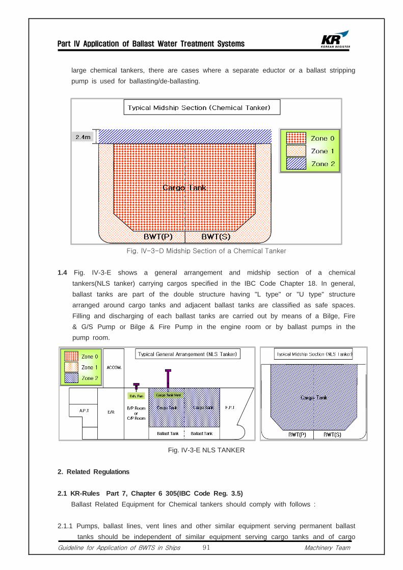
Part IV Application of Ballast Water Treatment Systems
Guideline for Application of BWTS in Ships Machinery Team91
large chemical tankers, there are cases where a separate eductor or a ballast stripping pump is used for ballasting/de-ballasting.
Fig. IV-3-D Midship Section of a Chemical Tanker
1.4 Fig. IV-3-E shows a general arrangement and midship section of a chemical tankers(NLS tanker) carrying cargos specified in the IBC Code Chapter 18. In general, ballast tanks are part of the double structure having "L type" or "U type" structure arranged around cargo tanks and adjacent ballast tanks are classified as safe spaces. Filling and discharging of each ballast tanks are carried out by means of a Bilge, Fire & G/S Pump or Bilge & Fire Pump in the engine room or by ballast pumps in the pump room.
Fig. IV-3-E NLS TANKER
2. Related Regulations
2.1 KR-Rules Part 7, Chapter 6 305(IBC Code Reg. 3.5) Ballast Related Equipment for Chemical tankers should comply with follows :
2.1.1 Pumps, ballast lines, vent lines and other similar equipment serving permanent ballast tanks should be independent of similar equipment serving cargo tanks and of cargo

Part IV Application of Ballast Water Treatment Systems
Guideline for Application of BWTS in Ships Machinery Team92
tanks themselves. Discharge arrangements for permanent ballast tanks sited immediately adjacent to cargo tanks should be outside machinery spaces and accommodation spaces. Filling arrangement may be in machinery spaces provided that such arrangements ensure filling from tank deck level and non-return valves are fitted.
2.1.2 Filling of ballast in cargo tanks may be arranged from deck level by pumps serving permanent ballast tanks provided that the filling line has no permanent connection to cargo tanks or piping, and non-return valves are fitted.
2.1.3 Bilge pumping arrangements for cargo pump rooms, pump rooms, void spaces, slop tanks, double bottom tanks and similar spaces should be situated entirely within cargo areas except for void spaces, double bottom tanks and ballast tanks were such spaces are separated from tanks containing cargo or residues of cargo by a double bulkhead.
2.2 KR-Guidance Part 7, Chapter 6 305
2.2.1 General 1) The discharge arrangements of permanent ballast tanks adjacent to cargo tanks
may be such that ballast pumps in a machinery space are used as given as Fig. IV-3-F of the Guidance, and ballast or bilge is discharged overboard through the eductor in the cargo pump room. In this case, a check valve is to be provided between the ballast pump and eductor, and the spool piece is to be provided on weather deck within cargo areas.
Fig. IV-3-F Discharge Arrangement of Ballast tank
2) In Chapter 7, part 6, 305.1 of the KR-rule, it is stated that "Filling arrangements may be in the machinery spaces provided that such arrangements ensure filling from tank deck level and non return valves are fitted" which refers to cases where pipes exclusively used for filling but can not be used for discharging are fitted with stop valves and check valves that are operable from weather deck or stop valves on weather deck. Also, stability requirements must be sustained in the event of progressive flooding due to damage in the piping system and due consideration
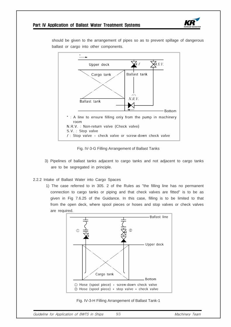
Part IV Application of Ballast Water Treatment Systems
Guideline for Application of BWTS in Ships Machinery Team93
should be given to the arrangement of pipes so as to prevent spillage of dangerous ballast or cargo into other components.
Fig. IV-3-G Filling Arrangement of Ballast Tanks
3) Pipelines of ballast tanks adjacent to cargo tanks and not adjacent to cargo tanks are to be segregated in principle.
2.2.2 Intake of Ballast Water into Cargo Spaces 1) The case referred to in 305. 2 of the Rules as "the filling line has no permanent
connection to cargo tanks or piping and that check valves are fitted" is to be as given in Fig 7.6.25 of the Guidance. In this case, filling is to be limited to that from the open deck, where spool pieces or hoses and stop valves or check valves are required.
Fig. IV-3-H Filling Arrangement of Ballast Tank-1
Part IV Application of Ballast Water Treatment Systems
Guideline for Application of BWTS in Ships Machinery Team94
2) When filling is made from open deck according to the preceding (1), the piping arrangement in cargo tanks is to be such that filling pipes are extended as close to the bottom as practicable to minimize generation of static electricity.
3. Protection for dangerous spaces and electrical equipment
3.1 Dangerous Spaces in Chemical Tankers Carrying Chemical Cargoes Having a Flash Point Below 60℃
For chemical takers carrying chemical cargoes having a flash point of 60℃ or below,
dangerous space is classified under space 0, space 1, and space 2 according to the probability of existence of flammable oil mist and its dangerousness, where each level demands different requirements for electrical Installation. Ballast tanks related to the BWTS, and a cargo pump room where the BWTS is likely to be installed are classified as space 1. And a space up to 2.4m above the cargo deck is classified as space 2. Therefore, when installing electrical equipment in the said dangerous spaces, special consideration for explosion-protection requirements should be taken into account. Fig. IV-3-A~D are examples of typical dangerous spaces in chemical tankers. For more information regarding dangerous spaces and protection of electrical equipment, please refer to Appendix "Hazardous Areas and Requirements for Electrical Installation in Each Ship Type", chapter 2.
3.2 Dangerous Spaces in Chemical Tankers Carrying Chemical Cargoes Having a Flash Point Above 60℃.
In chemical tankers carrying chemical cargoes having a flash point above 60℃, cargo tanks, cargo tank ventilation pipes and the inside of cargo pipes are, according to IEC 60092-502 Reg.4.3, classified as space 2. Fig. IV-3-E is an example of areas that are generally classified as dangerous spaces in NLS Tankers.
4. Installation of BWTS
4.1 Installation of BWTS in Chemical Tankers Carrying Chemical Cargoes Having a Flash Point of 60℃ or below.
Fig. IV-3-A, B and C are examples showing dangerous spaces in chemical tankers carrying chemical cargoes having a flash point of 60℃ or below. According to the BWM Convention/Guidelines/G8 Part 4.9, any electrical equipment that is part of the BWTS should be installed in a non-hazardous area, or should be certified by the Administration as safe for use in a hazardous area. Any moving parts, which are fitted in hazardous areas, should be arranged so as to avoid the formation of static electricity.
4.1.1 Considerations for Installation Location In chemical tankers carrying chemical cargoes having a flash point of 60 or below,
the BWTS should be installed in the areas as mentioned in above 3.1 unless it is certified for safe use in hazardous areas. However, since ballast tanks are classified

Part IV Application of Ballast Water Treatment Systems
Guideline for Application of BWTS in Ships Machinery Team95
as hazardous areas, all related pipes are also classified as space 1. For the reason, electric components of the BWTS such as treatment units or sensors that are directly connected to the ballast pipe should be of certified explosion-proof type.
1) Installation of BWTS in Cargo Pump Room or Ballast Pump Room. The BWTS may be installed in a cargo pump room or ballast pump room if a
chemical tanker has such a space. Fig. IV-2-I is an outline diagram showing the installation of the BWTS in the cargo pump room. Any electrical equipment that is part of the BWTS should be of type approved explosion-proof type.
2) Installation in Areas Other than Engine Room or Pump Room It is difficult to find a suitable installation space in chemical tankers not having a
cargo pump room or ballast pump room since the installation of the BWTS in the engine room or accommodation area is prohibited. In this case, the BWTS may be installed on upper deck. Fig. IV-3-K is an example showing the installation of BWTS on upper deck. The following should be considered when installing the BWTS on upper deck.
Fig IV-3-I Installation of BWTS in Pump Room
Fig. IV-3-J Installation of BWTS Outside the Pump Room
a. In case that the BWTS is installed on ship's upper deck requiring ballast water to be pumped up to the BWTS, head loss of the ballast pump should be considered. Also, excessive vacuum may be found in the ballast pipes when shifting the ballast water downstream from an elevated place, hence countermeasures such as installation of vacuum valves should be considered.
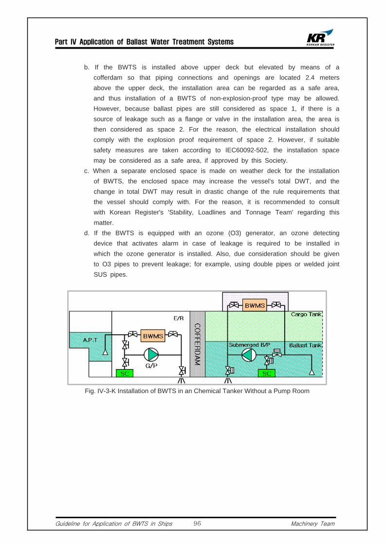
Part IV Application of Ballast Water Treatment Systems
Guideline for Application of BWTS in Ships Machinery Team96
b. If the BWTS is installed above upper deck but elevated by means of a cofferdam so that piping connections and openings are located 2.4 meters above the upper deck, the installation area can be regarded as a safe area, and thus installation of a BWTS of non-explosion-proof type may be allowed. However, because ballast pipes are still considered as space 1, if there is a source of leakage such as a flange or valve in the installation area, the area is then considered as space 2. For the reason, the electrical installation should comply with the explosion proof requirement of space 2. However, if suitable safety measures are taken according to IEC60092-502, the installation space may be considered as a safe area, if approved by this Society.
c. When a separate enclosed space is made on weather deck for the installation of BWTS, the enclosed space may increase the vessel's total DWT, and the change in total DWT may result in drastic change of the rule requirements that the vessel should comply with. For the reason, it is recommended to consult with Korean Register's 'Stability, Loadlines and Tonnage Team' regarding this matter.
d. If the BWTS is equipped with an ozone (O3) generator, an ozone detecting device that activates alarm in case of leakage is required to be installed in which the ozone generator is installed. Also, due consideration should be given to O3 pipes to prevent leakage; for example, using double pipes or welded joint SUS pipes.
Fig. IV-3-K Installation of BWTS in an Chemical Tanker Without a Pump Room

Part IV Application of Ballast Water Treatment Systems
Guideline for Application of BWTS in Ships Machinery Team97
Fig. IV-3- Installation of BWTS in an Chemical Tanker without a Pump Room
e. If the BWTS is such a type that generates hazardous gas such as hydrogen gas after treatment, discharge pipes of the hazardous gas should be led to a safe area outside the enclosed space since the hazardous gas may be accumulated in the enclosed space.
f. When installing the BWTS on weather deck, a suitable IP grade should be selected for the components that are parts of the BWTS.
3) Installation in Engine Room The BWTS and a direct sampling device should not be installed in chemical
tanker's engine room except when the chemical tankers are carrying chemical cargoes having a flash point above 60℃. However, in most cases, chemical tankers use Bilge, Fire & G/S Pumps or Bilge & Fire Pumps in the engine room for filling/discharging ballast water in/out of A.P.T. Also, filling of A.P.T which is generally considered a safe area is carried out using Bilge, Fire & G/S Pumps or Bilge & Fire Pumps in the engine room while discharging is carried out using ballast pumps in the ballast pump room. In these cases, the following should be considered.
a. A dedicated BWTS for the treatment of ballast water in A.P.T or F.P.T where considered a space, should be installed in a safe space such as an engine room. However, it is to be noted that for those BWTS that require additional treatment process during discharging, ballast piping is generally designed to use ballast pumps in the ballast pump room during discharging, thus use of the BWTS in the engine room may not be possible.
b. If the BWTS is equipped with an ozone (O3) generator, an ozone detecting device that activates alarm in case of leakage is required to be installed in which the ozone generator is installed. Also, due consideration should be given to O3 pipes to prevent leakage; for example, using double pipes or welded joint SUS pipes.
c. If the BWTS is such a type that generates hazardous gas such as hydrogen gas after treatment, discharge pipes of the hazardous gas should be led to a
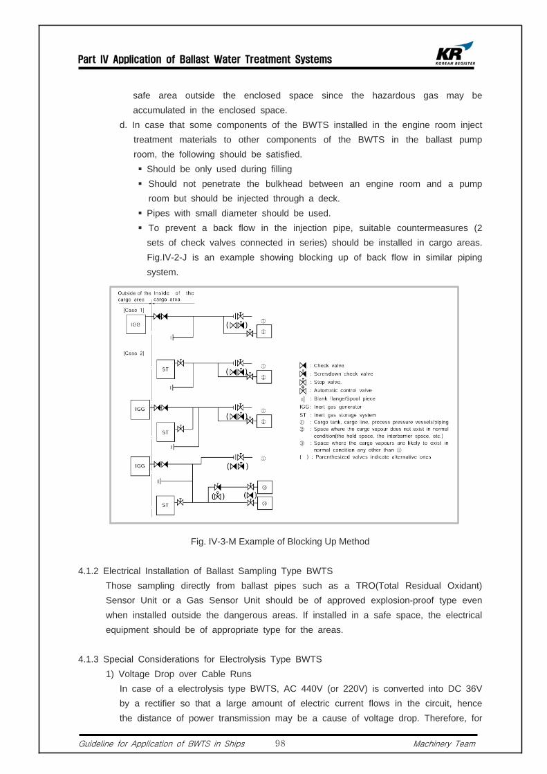
Part IV Application of Ballast Water Treatment Systems
Guideline for Application of BWTS in Ships Machinery Team98
safe area outside the enclosed space since the hazardous gas may be accumulated in the enclosed space.
d. In case that some components of the BWTS installed in the engine room inject treatment materials to other components of the BWTS in the ballast pump room, the following should be satisfied.
Should be only used during filling Should not penetrate the bulkhead between an engine room and a pump
room but should be injected through a deck. Pipes with small diameter should be used. To prevent a back flow in the injection pipe, suitable countermeasures (2
sets of check valves connected in series) should be installed in cargo areas. Fig.IV-2-J is an example showing blocking up of back flow in similar piping system.
Fig. IV-3-M Example of Blocking Up Method
4.1.2 Electrical Installation of Ballast Sampling Type BWTS Those sampling directly from ballast pipes such as a TRO(Total Residual Oxidant)
Sensor Unit or a Gas Sensor Unit should be of approved explosion-proof type even when installed outside the dangerous areas. If installed in a safe space, the electrical equipment should be of appropriate type for the areas.
4.1.3 Special Considerations for Electrolysis Type BWTS 1) Voltage Drop over Cable Runs In case of a electrolysis type BWTS, AC 440V (or 220V) is converted into DC 36V
by a rectifier so that a large amount of electric current flows in the circuit, hence the distance of power transmission may be a cause of voltage drop. Therefore, for

Part IV Application of Ballast Water Treatment Systems
Guideline for Application of BWTS in Ships Machinery Team99
safe operation, the length of cables should be within manufacturer's recommendation.
2) Composition of Cable Runs Using Bus-bar The electrolysis type BWTS, when its capacity become larger, the required electric
current transmission also become larger resulting in increase in size and number of cables. For the reason, a Bus-bar is often used to reduce the installation space. In this case, the Bus-bars should be of KR type-approved and be installed in a trunk whose protection grade is IP54 or above. Installation in dangerous spaces or on weather deck should be avoided. If installed in dangerous spaces, the Bus-bar should be explosion-protection type. Particularly, when penetrating a boundary between a safe area and a dangerous space, fire protection and sealing requirements for penetrating pieces should be complied with. Also, on-board installation methods and the details of penetration parts should be approved by this Society.
4.1.4 General Requirements for Electrical Equipment in Chemical Tanker's Dangerous Area. According to KR-Rules Part 7 Chapter 6 Section 10, the following requirements should
be satisfied. 1) Electrical installations should be such as to minimize the risk of fire and explosion
from flammable products. 2) Ships carrying a specific cargo which is liable to damage materials that are
normally used in electrical apparatus, due consideration should be given to the particular characteristics of materials chosen for conductors, insulation and metal parts, etc. As far as necessary, these components should be protected to prevent contact with gas or vapour liable to be encountered.
3) If the flash point of a substance is in excess of 60°C however being heated within 15°C above the flash point, the requirements for cargoes having a flash point not exceeding 60°C may be applied.
4) Independent cargo tanks should be electrically bonded to the hull. All cargo pipe joints and hose connections having gaskets should be electrically bonded.
5) Disconnection Switch Each distribution circuit for electrical equipment installed in dangerous spaces
should be provided with multi pole linked isolation switches installed in a safe space. In addition, the isolation switches are to be clearly labelled to identify the electrical equipment to be connected with, and further effective means are to be provided to avert danger due to unauthorized operation of the isolation switches.
6) Monitoring of Insulation Level Excluding intrinsically safe circuits, feeder and distribution circuits that are in
contact with electrical equipment or run through dangerous spaces are to be provided with a system that monitors insulation level and activates alarm in case of abnormal condition.

Part IV Application of Ballast Water Treatment Systems
Guideline for Application of BWTS in Ships Machinery Team100
5) Cable
a. Cables are to be of armored Non-metallic Sheath Type. b. Cables are to be installed as close to the hull centre line as practicable. c. Cables are sufficiently distant from decks, bulkheads, tanks and various kinds of
pipes. d. Cables, which are installed on the passages and the decks, are to be protected
against mechanical damage. Further, the cables and their supports are to be fitted in such a manner as to withstand expansion and contraction and other effects of the hull structure.
e. The penetration parts of the cables or cable pipes through decks and bulkheads of the dangerous spaces are to be constructed so as to maintain gas-tightness and liquid-tightness as the case may require.
f. When mineral insulated cables are used, special precaution is to be taken to ensure sound terminations.
g. All metallic protective coverings of power and lighting cables passing through dangerous spaces, or connected to equipment in such spaces, are to be earthed at least at each end.
4.1.5 Installation Examples Fig. IV-3-N and O are examples showing the installation of BWTS in a dangerous
area of chemical tankers carrying chemical cargoes having a flash point below 60℃. The ballast treatment equipment and sensors installed in ballast pipes inside the red box in Fig IV-3-N and O are explosion-proof type and other non-explosion protected equipment is arranged outside the dangerous spaces. In addition, sensors directly connected to ballast pipes such as FMU (Flow Meter Unit) are to be of explosion proof type.
4.2 Chemical Tankers Dedicated to Carry Cargoes Specified in IBC Code Chapter 18. If the BWTS is installed outside the dangerous spaces as in above 3.2, ballast tanks
are not considered as dangerous spaces and thus the BWTS is not required to be explosion-proof type.
4.3 Measures for Pipes and Penetration Parts of Cables The penetrating parts of pipes and cables for the BWTS, when penetrating bulkheads or
decks, are required to be of the same water-tight or fire protection level to that of the penetrated bulk heads or the decks. Additionally, when the cable is penetrating a boundary between safe spaces and dangerous spaces, gas-tight requirements should be complied with. For more details about the penetrating parts, please refer to "KR-Rules Part 8, Annex 8-2 "Penetrations through Divisions".
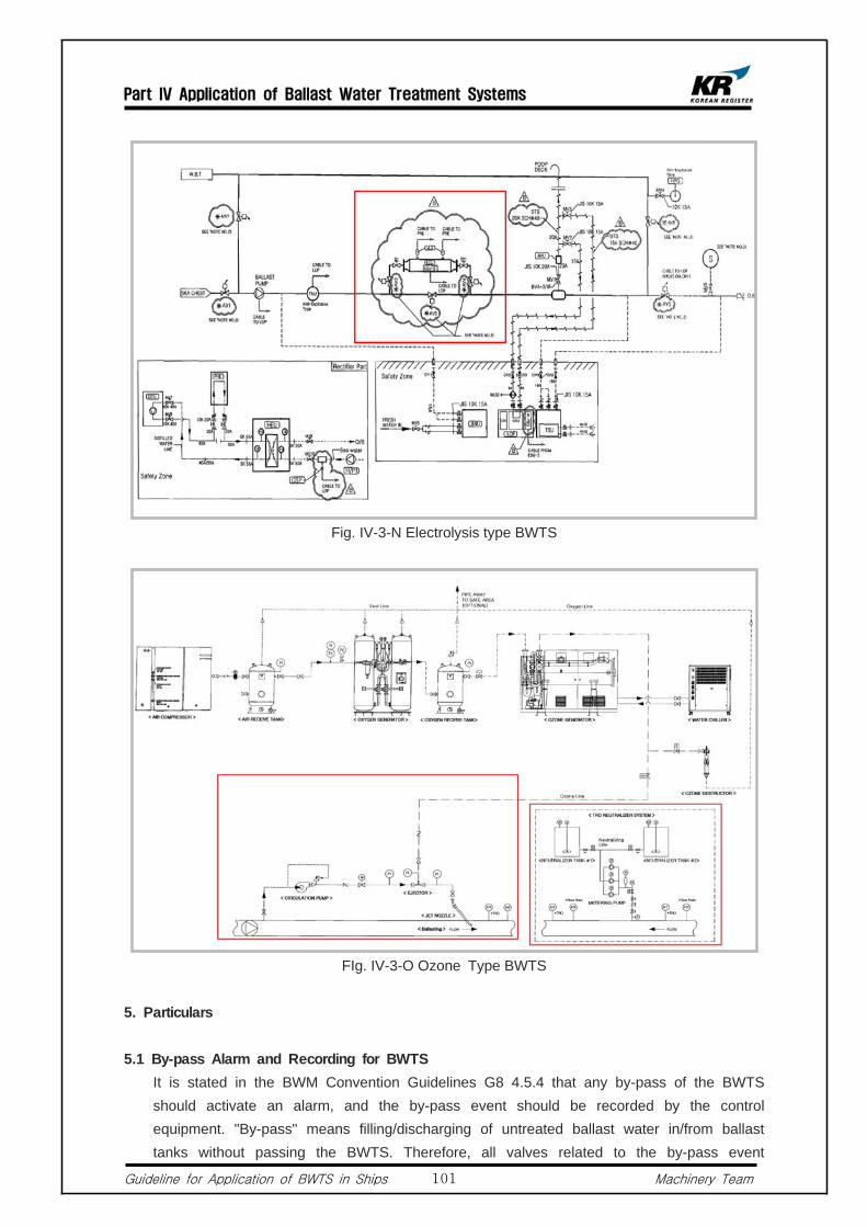
Part IV Application of Ballast Water Treatment Systems
Guideline for Application of BWTS in Ships Machinery Team101
Fig. IV-3-N Electrolysis type BWTS
FIg. IV-3-O Ozone Type BWTS
5. Particulars
5.1 By-pass Alarm and Recording for BWTS It is stated in the BWM Convention Guidelines G8 4.5.4 that any by-pass of the BWTS
should activate an alarm, and the by-pass event should be recorded by the control equipment. "By-pass" means filling/discharging of untreated ballast water in/from ballast tanks without passing the BWTS. Therefore, all valves related to the by-pass event

Part IV Application of Ballast Water Treatment Systems
Guideline for Application of BWTS in Ships Machinery Team102
should be of remote controllable type or be equipped with an open/close indicator so that automatic detection and alarm is enabled from BWTS's control device.
5.1.1 Installation in Narrow Space In general, 2 or more ballast pumps are installed onboard ships, and in most of the
cases, ballast water is filled/discharged in/out of ballast tanks via 2 main ballast pipes on the ballast pump's discharge side. However in small ships, there are cases where the BWTS is installed on only one side of ballast pipes due to limited installation space. In this case, the below design considerations should be taken into account. Fig. IV-2-M is an example where the BWTS is installed on only one side of main ballast pipes.
1) All pipes related to the by-pass of BWTS should be removed, or an automatic alarm system activated in the event of by-pass should be equipped for all valves that may cause by-pass when adjusted. And the by-pass event should be recorded by the control equipment.
2) In general, although 2 ballast pumps are used, ballast water is carried through 1 main pipe line. For the reason, design consideration such as over pressure of pipe or excessive flow of ballast water into the BWTS should be taken into account (In general, piping system is designed for abt. 2~3m/s)
Fig. IV-3-P Example of Installation Where the BWTS is Installed in Only One Side of the Main Ballast Lines
5.1.2 Initial Operation of BWTS For a BWTS that requires by-pass or re-circulation for some periods during its initial
operation, valves controling filling and discharging are generally designed to have an automatic interlock function to prevent filling/discharging of untreated ballast water flow.

Part IV Application of Ballast Water Treatment Systems
Guideline for Application of BWTS in Ships Machinery Team103
This design feature is included in the most type approval conditions or stated in type approval drawings. Especially, when installing this type of BWTS in existing ships, the type and arrangement of automatic control valves and interlock valves should be checked, and the capacity of hydraulic power pack should be sufficient. Also, initial operation procedure should be included in the BWTS' operation manual that is to be furnished onboard ships.
5.1.3 Eductor for Ballast Water Stripping Ships having large-capacity ballast tanks such as chemical tankers, often equip with
an eductor for the purpose of striping ballast tanks. If this kind of ship is equipped with a BWTS that requires the post-treatment of ballast water when discharging, the system should be designed so that all flows through stripping pipes are treated by the BWTS. In addition, all pipes that may enable the BWTS to by-pass should be removed, or an automatic audible/visual alarm system activated in the event of by-pass is to be equipped for all valves connected to striping pipes. And the by-pass event should be recorded by the control equipment. Below Fig. IV-3-Q is an example showing a ballast piping system where a stripping eductor is installed.
Fig. IV-3-Q Ballast Piping System with a Stripping Eductor
5.1.4 Retroactive application to existing vessels In most existing ships, 2 or more ballast pumps are installed, and their discharge
outlets are connected to ballast tanks through 2 main ballast pipes. However, in small ships, there are cases where the BWTS is connected to only 1 of the main ballast pipes due to the limited installation space. In such cases, the following should be considered.
1) All pipes related to the by-pass of BWTS should be removed or, all valves related
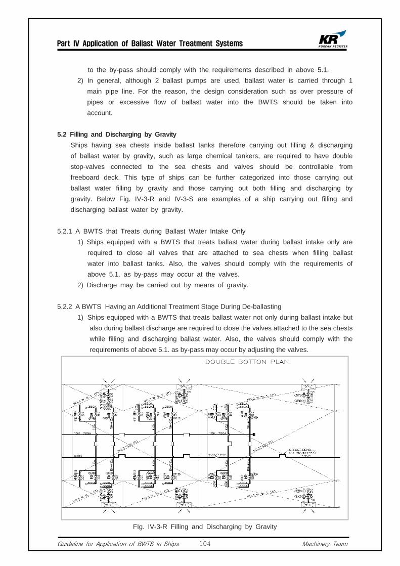
Part IV Application of Ballast Water Treatment Systems
Guideline for Application of BWTS in Ships Machinery Team104
to the by-pass should comply with the requirements described in above 5.1. 2) In general, although 2 ballast pumps are used, ballast water is carried through 1
main pipe line. For the reason, the design consideration such as over pressure of pipes or excessive flow of ballast water into the BWTS should be taken into account.
5.2 Filling and Discharging by Gravity Ships having sea chests inside ballast tanks therefore carrying out filling & discharging
of ballast water by gravity, such as large chemical tankers, are required to have double stop-valves connected to the sea chests and valves should be controllable from freeboard deck. This type of ships can be further categorized into those carrying out ballast water filling by gravity and those carrying out both filling and discharging by gravity. Below Fig. IV-3-R and IV-3-S are examples of a ship carrying out filling and discharging ballast water by gravity.
5.2.1 A BWTS that Treats during Ballast Water Intake Only 1) Ships equipped with a BWTS that treats ballast water during ballast intake only are
required to close all valves that are attached to sea chests when filling ballast water into ballast tanks. Also, the valves should comply with the requirements of above 5.1. as by-pass may occur at the valves.
2) Discharge may be carried out by means of gravity.
5.2.2 A BWTS Having an Additional Treatment Stage During De-ballasting 1) Ships equipped with a BWTS that treats ballast water not only during ballast intake but
also during ballast discharge are required to close the valves attached to the sea chests while filling and discharging ballast water. Also, the valves should comply with the requirements of above 5.1. as by-pass may occur by adjusting the valves.
FIg. IV-3-R Filling and Discharging by Gravity

Part IV Application of Ballast Water Treatment Systems
Guideline for Application of BWTS in Ships Machinery Team105
Fig. IV-3-S Filling and Discharging by Gravity
5.3 Ballast Water Discharge by Gravity
5.3.1 A BWTS that Treats during De-ballasting only 1) Ships designed to discharge ballast water by gravity, if a BWTS that treats ballast
water during filling only is installed, may discharge the ballast water by gravity. 2) There should be no ingress of untreated ballast water into ballast tanks when filling
ballast water. For the reason, check valves should be used in the discharge section. If stop valves are used, the requirements in above 5.1 should be met since by pass may occur at the stop valve.
5.3.2 A BWTS having an Additional Treatment Stage During De-ballasting 1) Ships equipped with a BWTS having an additional treatment stage during
de-ballasting are required to close the valves that are attached to the sea chests at all times. Also, the valves should comply with the requirements of above 5.1. as by-pass may occur at the valves.
2) Above 1) should be considered, in particular, if an overflow pipe for the ballast exchange is installed in an existing ship for the purpose of complying with the BWM Convention D1 (Ballast Water Exchange Method).
5.4 Cargo Holds Used as Ballast Tanks Generally, chemical tankers are capable of filling ballast water into cargo holds in case
of heavy weather or emergency. In most chemical tankers, a piping system is designed to enable pumping of ballast water from cargo holds not by ballast pumps but by cargo pumps, which is then discharged overboard via discharge piping that complies with the requirements of MARPOL ANNEX 2. For the reason, where the BWTS that requires post treatment during discharging is installed onboard, the following should be considered.
5.4.1 Cargo tank piping system should be designed so that discharging is possible.

Part IV Application of Ballast Water Treatment Systems
Guideline for Application of BWTS in Ships Machinery Team106
5.4.2 There may be oily impurities in cargo tanks which may reduce the performance of
BWTS during discharging. Therefore, due consideration should be given when choosing or arranging the BWTS.
5.4.3 It is to be considered that a UV lamp type BWTS, whose UV lamps are in directly contact with ballast water, may have an auto cleaning function, however this function may not perform well with oily substances.
5.5 When Using Ballast Pump for Other Purposes For ships whose fire pumps also serve as ballast pumps, if the BWTS is of
remote-controllable type, valves in the in/outlet of the fire pumps should also be remote-controllable. The same should be applied when bilge pumps serve as ballast pumps.
5.6 Ships having a KR Class Notation of UMA or Above Ships registered to KR and having a Class Notation of UMA or above (UMA, UMA1,
UMA2, UMA3) are required to equip with a remote-controllable fire pump according to KR-Rules Pt 9, Ch 3. Hence, those using the fire pump also for ballasting should take above into account.
5.7 Ships with a KR Class Notation of UMA1 or above Ships registered to this Society and having a Class Notation of UMA1 or above (UMA,
UMA1, UMA2, UMA3) are, according to KR-Rules Pt 9, Ch 3, 502.1 , required to equip with a system that can control ballasting remotely. Hence, for ships with UMA1 or above and having a BWTS installed onboard, all valves related to the filling/discharging of ballast water or operation of the BWTS should be remote controllable.
5.8 Astern F.P.T In principle, it is not allowed to use the BWTS in the pump room for the treatment of
ballast water in the F.P.T, which is considered as a safe space. However, such a case may be permitted if the following conditions are satisfied (Refer to IACS UR F44).
5.8.1 The F.P.T is considered as a dangerous space.
5.8.2 Air pipe openings of the F.P.T should be installed on weather deck separated from ignition sources by the distance set out by IEC 60092-502.
5.8.3 There should be a means of measuring concentration of flammable gas in the F.P.T. In this case, a detector tube led to weather deck and a portable detector should be arranged.
5.8.4 Sounding pipes of the F.P.T should be led to weather deck.

Part IV Application of Ballast Water Treatment Systems
Guideline for Application of BWTS in Ships Machinery Team107
5.8.5 The entrance of the F.P.T should be directly accessible from an open deck. However, entrance to the F.P.T via a confined space may be permitted if following conditions are met.
1) If the enclosed space is not adjacent to cargo tanks, the entrance of the F.P.T should be of a gas-tight manhole. In this case, a warning plate, describing that the door should be opened after checking non-existence of flammable gas in the F.P.T or shutting off electrical equipment other than explosion-proof type, should be attached on the manhole.
2) If adjacent to cargo tanks, the enclosed space is classified as a dangerous space. Therefore it should comply with all the related requirements. Also, efficient means of ventilation should be arranged.
5.9 Fire integrity for Areas Where BWTS Is Installed. The BWTS can also be installed in a space inside the deckhouse. In this case, the
said space is defined, according to SOLAS Reg. II-2/3 regulation, as a machinery space or service space. For the reason, bulkheads or decks of living areas adjacent to the machinery space or service space are required to have fire integrity of A-0 or above according to SOLAS Reg. II-2/9 regulation.
5.10 Fresh Water Tank When a fresh water tank is served as a ballast tank, chemicals contained in the fresh
water may potentially be discharged. In this regards, the application of the BWM Convention to portable water is under discussion at IMO.
5.11 Electric Consumption and Composition of Electric Circuit Electrical load analysis should be carried out and the result should be submitted to this
Society to make sure that the electric power installed on-board is sufficient to cover the increased electric consumption. Also, BWTS's electrical equipment should be protected from overloading or short-circuit.
5.12 Modification of Ballast Tanks According to the BWM Convention Annex A-1, Reg.5, an existing ship carrying out
major conversion is considered as a new ship. "Major conversion" means a conversion of a ship :
1) which changes its ballast water carrying capacity by 15% or greater, or 2) which changes the ship type, or 3) which, approved by Administration, is projected to prolong its life by ten years or
more, or 4) which results in modification to its ballast water system other than component
replacement-in-kind.
5.13 Control, Monitoring and Alarm of BWTS The BWM Convention Guidance 8, Chapter4, describes the requirement of control
equipment and monitoring & alarm equipment.
Part IV Application of Ballast Water Treatment Systems
Guideline for Application of BWTS in Ships Machinery Team108
5.13.1 Control Device and Monitoring and Alarm Device 1) The injection amount or the injection level of BWTS that is required for the
treatment of ballast water should be controlled automatically. The control equipment should be capable of continuous self-monitoring during operation and operation related items should be automatically monitored and controlled.
2) Malfunction or errors occurring in the system should be monitored. And if this kind of problem affects operation of the BWTS, audible/visual alarm should be activated in all areas in which the ballast water treatment process is regulated.
5.13.2 Operation and Control 1) Operation and control of the BWTS should be simple and effective, and all
controls should be remote controllable, as far as practicable. However, this does not necessarily mean the automation of all valves related to the BWTS, but easy and effective manual operation is acceptable, except those that may cause the BWTS's malfunction. In this case, it is recommended that guidelines for the handling procedure of manual valves when filling/discharging ballast water and piping diagrams indicating related valves should be posted in all control areas.
2) Ships registered to this Society and having a notation of UMA1 or above are required that all valves related to the operation of BWTS and ballast pumps should be remote controllable, and such a system should be interconnected with the existing remote control devices of the ballast pumps for automatic control.
5.13.3 By-pass and Override 1) Ships equipped with a BWTS should install a means of by-pass or override for
the protection of the ships or their crews in case of emergency. Also, in case of by-pass, audible/visual alarm should be activated automatically by the monitoring system and the by-pass event should be recorded in the control system.
2) In case of existing ships, the BWTS is generally installed in one side of the ballast lines. For the reason, the usage of other ballast lines should be monitored. In relation to this, suppliers should submit the list of situations where by-pass may occur considering the ships's ballast piping arrangements for review.
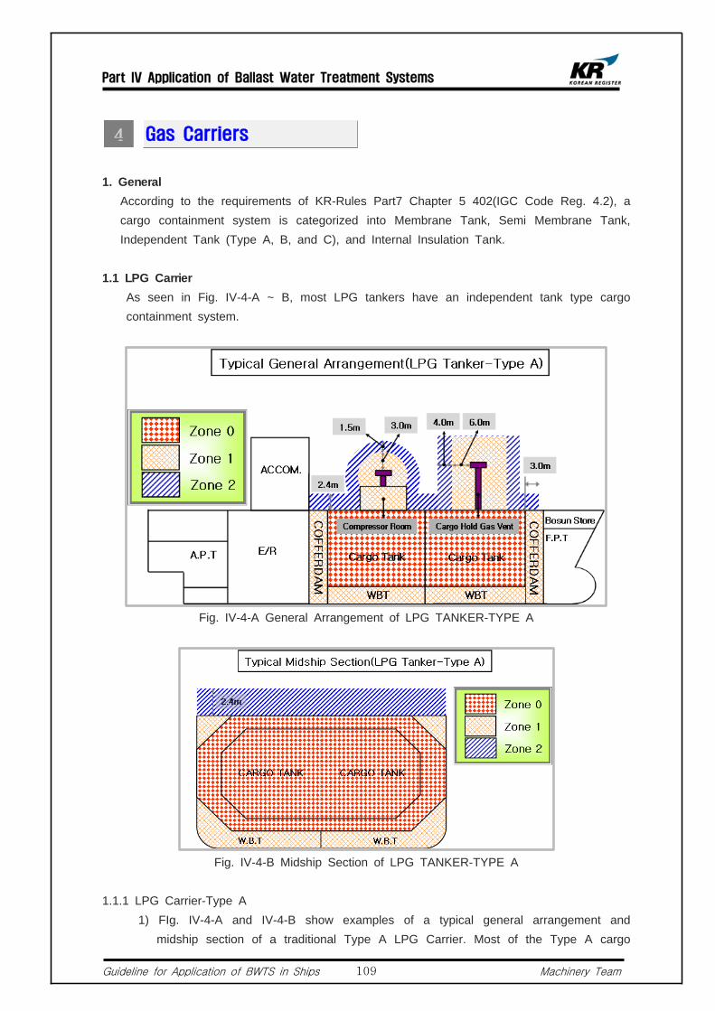
Part IV Application of Ballast Water Treatment Systems
Guideline for Application of BWTS in Ships Machinery Team109
Gas Carriers
1. General According to the requirements of KR-Rules Part7 Chapter 5 402(IGC Code Reg. 4.2), a
cargo containment system is categorized into Membrane Tank, Semi Membrane Tank, Independent Tank (Type A, B, and C), and Internal Insulation Tank.
1.1 LPG Carrier As seen in Fig. IV-4-A ~ B, most LPG tankers have an independent tank type cargo
containment system.
Fig. IV-4-A General Arrangement of LPG TANKER-TYPE A
Fig. IV-4-B Midship Section of LPG TANKER-TYPE A
1.1.1 LPG Carrier-Type A 1) FIg. IV-4-A and IV-4-B show examples of a typical general arrangement and
midship section of a traditional Type A LPG Carrier. Most of the Type A cargo

Part IV Application of Ballast Water Treatment Systems
Guideline for Application of BWTS in Ships Machinery Team110
containment systems are maintained at low temperature and low pressure, and widely applied in medium to large LPG Carriers having cargo tank capacity of 20K, 40K, or 80K.
2) As shown in the midship section of Fig.62, type A LPG carriers having an independent type cargo containment system have separate hold spaces where the cargo containment system is confined by the ship's hull structure, and the ballast tanks are arranged alongside the hold spaces. However, because the hull structure may act as a 2nd barrier when the cargo space temperature is above -55℃ under atmospheric pressure, both Port & STBD side of the hold spaces and parts of the front side should not be in contact with ballast tanks. In addition, the midship section of a Type A LPG Carrier is similar to that of a typical single hull bulk carrier.
3) Installation of ballast pumps in the engine room is accepted according to KR-Rules Part 7 Chapter 5 307.4 (GC Code Reg. 3.7.4). For the reason, most of the type A LPG carriers have 2 sets of ballast pumps installed in the engine room in addition to Bilge, Fire & G/S Pumps or Bilge & Fire Pumps. Filling and discharging of A.P.T and all ballast tanks are carried out by means of ballast pumps. Furthermore, in case of large ships, there are cases where a separate ballast stripping pump such as an eductor is installed.
1.1.2 LPG Carrier-Type C 1) Fig. IV-4-C and D show the general arrangement and midship section of a typical
Type C LPG Carrier, respectively. In general, the Type C cargo tanks have ball or cylindrical shape. This type is commonly used in medium to small LPG Carrier having cargo tank capacity below 10K.
2) As shown in the midship section of Fig. IV-4-D, Type A LPG carriers having an independent type cargo containment system have separate hold spaces where the cargo containment system is confined by the ship's hull structure, and the ballast tanks are arranged alongside the hold spaces. Therefore, these ballast tanks are not in direct contact with the cargo containment system.
3) Installation of ballast pumps in the engine room is accepted according to the KR-Rule Part 7 Chapter 5 307.4 (IGC Code Reg. 3.7.4). Therefore, most type C LPG carriers carry out filling or discharging of A.P.T by means of Bilge, Fire & G/S Pumps or Bilge, Ballast & Fire Pumps in the engine room.
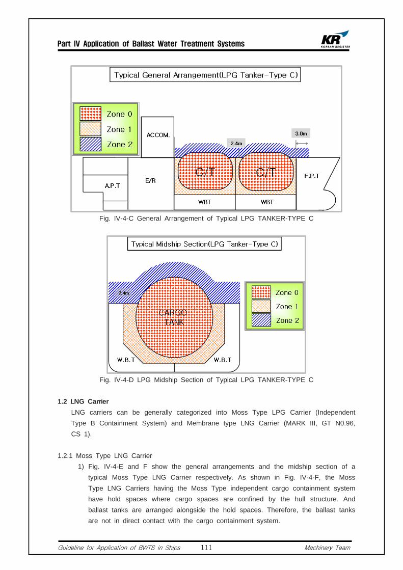
Part IV Application of Ballast Water Treatment Systems
Guideline for Application of BWTS in Ships Machinery Team111
Fig. IV-4-C General Arrangement of Typical LPG TANKER-TYPE C
Fig. IV-4-D LPG Midship Section of Typical LPG TANKER-TYPE C
1.2 LNG Carrier LNG carriers can be generally categorized into Moss Type LPG Carrier (Independent
Type B Containment System) and Membrane type LNG Carrier (MARK III, GT N0.96, CS 1).
1.2.1 Moss Type LNG Carrier 1) Fig. IV-4-E and F show the general arrangements and the midship section of a
typical Moss Type LNG Carrier respectively. As shown in Fig. IV-4-F, the Moss Type LNG Carriers having the Moss Type independent cargo containment system have hold spaces where cargo spaces are confined by the hull structure. And ballast tanks are arranged alongside the hold spaces. Therefore, the ballast tanks are not in direct contact with the cargo containment system.

Part IV Application of Ballast Water Treatment Systems
Guideline for Application of BWTS in Ships Machinery Team112
2) Installation of ballast pumps in the engine room is accepted according to the KR-Rules Part 7 Chapter 5 307.4 (GC Code Reg. 3.7.4). For the reason, most of the Moss Type LNG carriers have 2 sets of ballast pumps installed in the engine room in addition to Bilge, Fire & G/S Pumps or Bilge & Fire Pumps. And filling and discharging of A.P.T and all ballast tanks are carried out by means of ballast pumps. Furthermore, In case of large ships, there are cases where a separate ballast stripping pump such as an eductor is installed.
Fig. IV-4-E General Arrangement of LNG TANKER-MOSS TYPE
Fig. IV-4-F Midship Section of LNG TANKER-MOSS TYPE

Part IV Application of Ballast Water Treatment Systems
Guideline for Application of BWTS in Ships Machinery Team113
Fig. IV-4-G General Arrangement of LNG TANKER-MEMBRANE TYPE
Fig. IV-4-H Midship Section of LNG TANKER-MEMBRANE TYPE
1.2.2 Membrane Type LNG Carrier 1) The membrane type cargo constrainment system consists of the primary barrier that
houses LNG, the secondary barrier that houses the primary barrier and can contain the LNG for a limited period, and the Inner Hull Structure that supports these barriers. And ballast tanks are arranged between the inner hull structure and the ship's outer shell.
2) Fig. IV-4-G and H show typical general arrangement and midship section of a Membrane Type LNG Carrier respectively. As shown in Fig. IV-4-H, the cargo containment system of Membrane Type LNG Carrier consists of a primary barrier that contains the LNG cargo, a secondary barrier that houses the primary barrier and can contain the LNG cargo for a limited period, and the Inner Hull Structure that supports these barriers. And the ballast tanks are arranged between the inner hull structure and the ship's outer shell. Therefore, the ballast tanks are in direct contact with the cargo containment system.
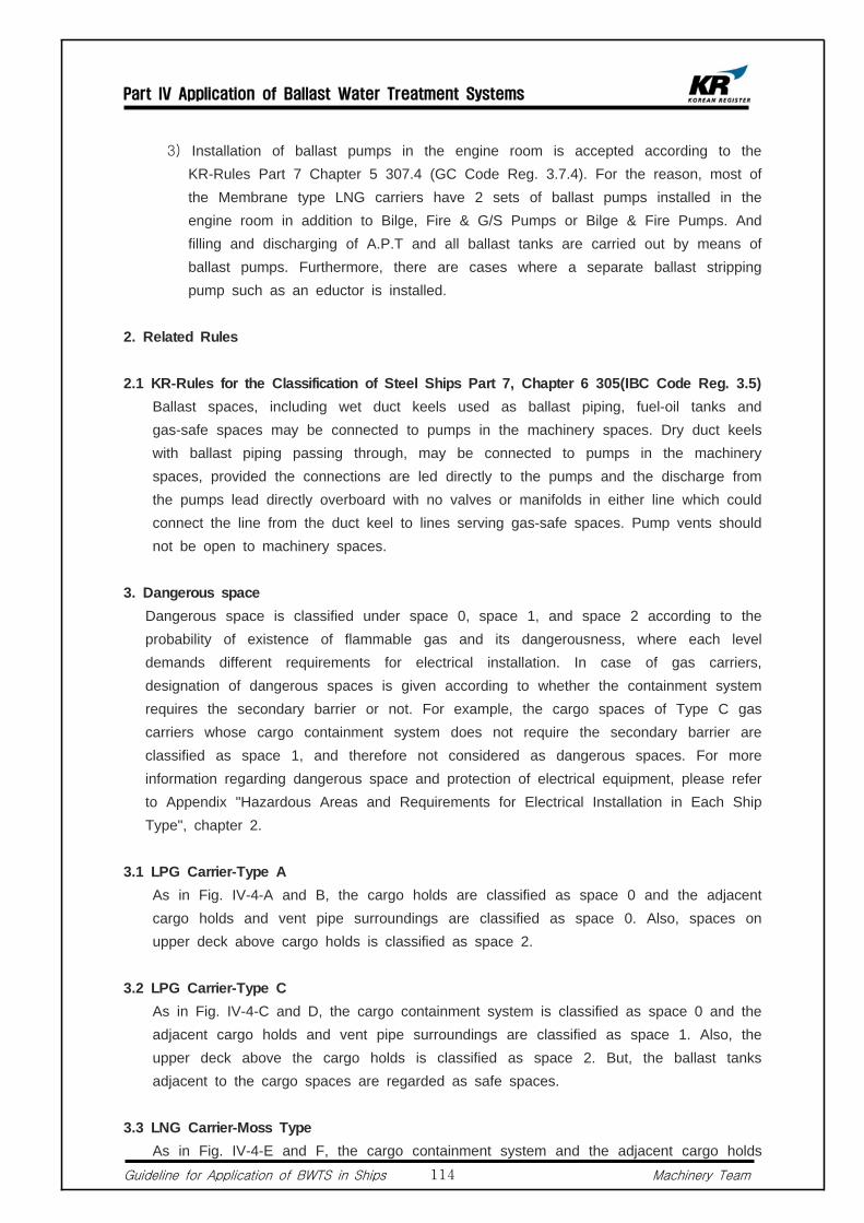
Part IV Application of Ballast Water Treatment Systems
Guideline for Application of BWTS in Ships Machinery Team114
3) Installation of ballast pumps in the engine room is accepted according to the KR-Rules Part 7 Chapter 5 307.4 (GC Code Reg. 3.7.4). For the reason, most of the Membrane type LNG carriers have 2 sets of ballast pumps installed in the engine room in addition to Bilge, Fire & G/S Pumps or Bilge & Fire Pumps. And filling and discharging of A.P.T and all ballast tanks are carried out by means of ballast pumps. Furthermore, there are cases where a separate ballast stripping pump such as an eductor is installed.
2. Related Rules
2.1 KR-Rules for the Classification of Steel Ships Part 7, Chapter 6 305(IBC Code Reg. 3.5) Ballast spaces, including wet duct keels used as ballast piping, fuel-oil tanks and
gas-safe spaces may be connected to pumps in the machinery spaces. Dry duct keels with ballast piping passing through, may be connected to pumps in the machinery spaces, provided the connections are led directly to the pumps and the discharge from the pumps lead directly overboard with no valves or manifolds in either line which could connect the line from the duct keel to lines serving gas-safe spaces. Pump vents should not be open to machinery spaces.
3. Dangerous space Dangerous space is classified under space 0, space 1, and space 2 according to the
probability of existence of flammable gas and its dangerousness, where each level demands different requirements for electrical installation. In case of gas carriers, designation of dangerous spaces is given according to whether the containment system requires the secondary barrier or not. For example, the cargo spaces of Type C gas carriers whose cargo containment system does not require the secondary barrier are classified as space 1, and therefore not considered as dangerous spaces. For more information regarding dangerous space and protection of electrical equipment, please refer to Appendix "Hazardous Areas and Requirements for Electrical Installation in Each Ship Type", chapter 2.
3.1 LPG Carrier-Type A As in Fig. IV-4-A and B, the cargo holds are classified as space 0 and the adjacent
cargo holds and vent pipe surroundings are classified as space 0. Also, spaces on upper deck above cargo holds is classified as space 2.
3.2 LPG Carrier-Type C As in Fig. IV-4-C and D, the cargo containment system is classified as space 0 and the
adjacent cargo holds and vent pipe surroundings are classified as space 1. Also, the upper deck above the cargo holds is classified as space 2. But, the ballast tanks adjacent to the cargo spaces are regarded as safe spaces.
3.3 LNG Carrier-Moss Type As in Fig. IV-4-E and F, the cargo containment system and the adjacent cargo holds
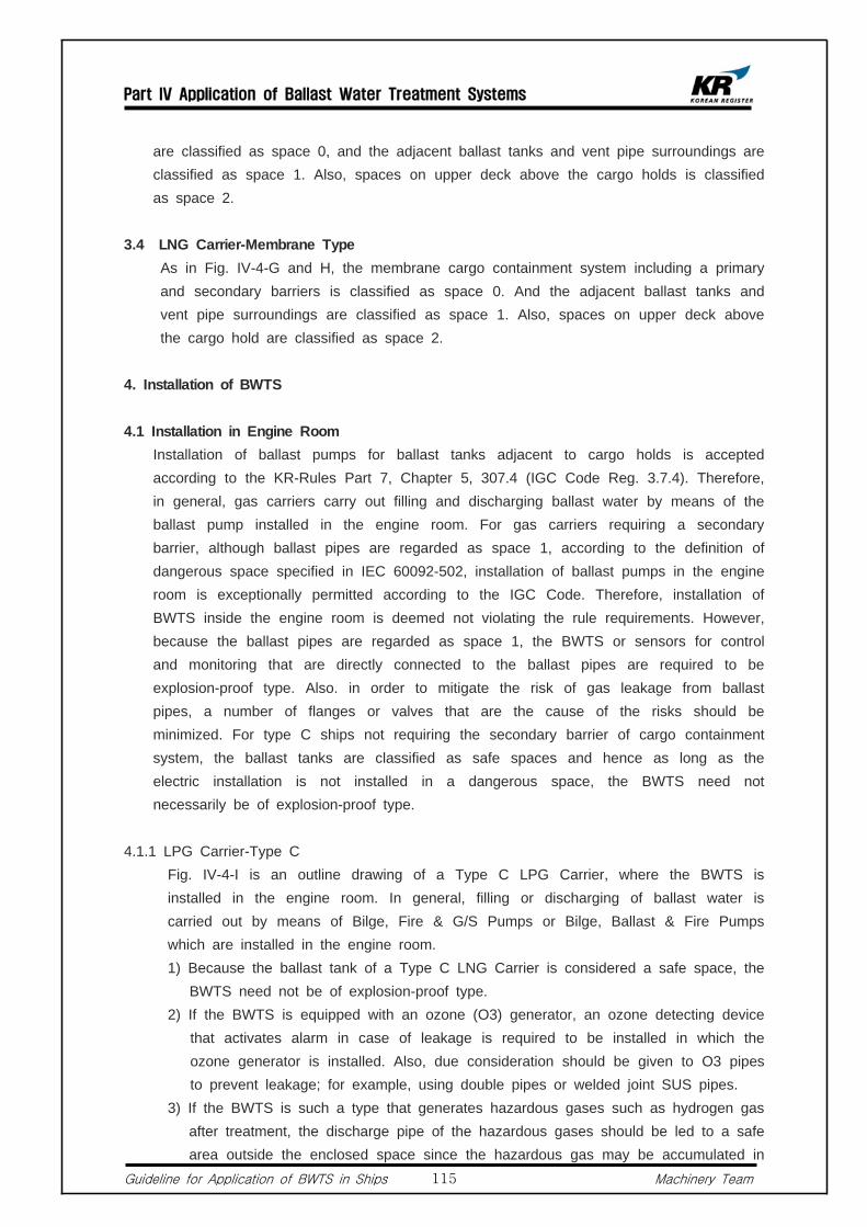
Part IV Application of Ballast Water Treatment Systems
Guideline for Application of BWTS in Ships Machinery Team115
are classified as space 0, and the adjacent ballast tanks and vent pipe surroundings are classified as space 1. Also, spaces on upper deck above the cargo holds is classified as space 2.
3.4 LNG Carrier-Membrane Type As in Fig. IV-4-G and H, the membrane cargo containment system including a primary
and secondary barriers is classified as space 0. And the adjacent ballast tanks and vent pipe surroundings are classified as space 1. Also, spaces on upper deck above the cargo hold are classified as space 2.
4. Installation of BWTS
4.1 Installation in Engine Room Installation of ballast pumps for ballast tanks adjacent to cargo holds is accepted
according to the KR-Rules Part 7, Chapter 5, 307.4 (IGC Code Reg. 3.7.4). Therefore, in general, gas carriers carry out filling and discharging ballast water by means of the ballast pump installed in the engine room. For gas carriers requiring a secondary barrier, although ballast pipes are regarded as space 1, according to the definition of dangerous space specified in IEC 60092-502, installation of ballast pumps in the engine room is exceptionally permitted according to the IGC Code. Therefore, installation of BWTS inside the engine room is deemed not violating the rule requirements. However, because the ballast pipes are regarded as space 1, the BWTS or sensors for control and monitoring that are directly connected to the ballast pipes are required to be explosion-proof type. Also. in order to mitigate the risk of gas leakage from ballast pipes, a number of flanges or valves that are the cause of the risks should be minimized. For type C ships not requiring the secondary barrier of cargo containment system, the ballast tanks are classified as safe spaces and hence as long as the electric installation is not installed in a dangerous space, the BWTS need not necessarily be of explosion-proof type.
4.1.1 LPG Carrier-Type C Fig. IV-4-I is an outline drawing of a Type C LPG Carrier, where the BWTS is
installed in the engine room. In general, filling or discharging of ballast water is carried out by means of Bilge, Fire & G/S Pumps or Bilge, Ballast & Fire Pumps which are installed in the engine room.
1) Because the ballast tank of a Type C LNG Carrier is considered a safe space, the BWTS need not be of explosion-proof type.
2) If the BWTS is equipped with an ozone (O3) generator, an ozone detecting device that activates alarm in case of leakage is required to be installed in which the ozone generator is installed. Also, due consideration should be given to O3 pipes to prevent leakage; for example, using double pipes or welded joint SUS pipes.
3) If the BWTS is such a type that generates hazardous gases such as hydrogen gas after treatment, the discharge pipe of the hazardous gases should be led to a safe area outside the enclosed space since the hazardous gas may be accumulated in

Part IV Application of Ballast Water Treatment Systems
Guideline for Application of BWTS in Ships Machinery Team116
the enclosed space.
Fig. IV-4-I Installation of BWTS in Engine Room : LPG Carrier-Type C
4.1.2 Gas Carriers Other than LPG Carrier-Type C FIg. IV-4-J, K and L are outline drawings showing installation of the BWTS in the
engine room of a Type A LPG Carrier, Moss Type LNG Carrier and Membrane Type LNG Carrier respectively. In general, filling and discharging of ballast water is carried out using dedicated ballast pumps installed in the engine room. As shown in Fig. IV-4-A&B and IV-4-E~H, ballast tanks adjacent to the cargo containment system are considered as space 1. But, according to the KR-Rules Part 7 Chapter 5 307.4 (IGC Code Reg. 3.7.4), installation of ballast pumps in the engine room for the purpose of filling/discharging adjacent to ballast tanks is accepted and therefore treatment of ballast water may be carried out by the BWTS installed in the engine room. Because the ballast tanks are classified as space 1, the following should be considered.
FIg. IV-4-J Installation of BWTS in Engine Room : LPG Carrier-Type A
1) A BWTS that treats during filling only may be exempted from explosion-protection requirements, only if approved by KR. But those requiring an additional treatment process during discharge, electrical installation for the control of the BWTS should be of approved explosion-proof type. In case of a non-explosion-proof type BWTS, the system should be designed so as to prevent random power supply to the BWTS while discharging.
2) Ships with a BWTS that treats ballast water during ballast intake and discharge, all

Part IV Application of Ballast Water Treatment Systems
Guideline for Application of BWTS in Ships Machinery Team117
electrical equipment of the BWTS related to ballast pipes are to be of approved explosion-proof type.
3) When installing a drain pipe in a TSU (TRO Sensor Unit) or a GSU (Gas Sensor Unit) which is part of the BWTS, the drain pipe should led to a safe space outside the enclosed space.
4) When installing air vent pipes on an AVU (Auto Air Vent Unit) which is installed as part of the BWTS, the air pipe should be led to a safe space outside the confined space.
5) A sampling pipe which is attached on the ballast discharge pipe should be led outside the enclosed space. If the BWTS is such a type that produces dangerous gas during treatment process, there is a risk of accumulation of dangerous gas in the enclosed space. For the reason, discharge pipes should be led to a safe space outside the enclosed space. If the BWTS is equipped with an ozone (O3) generator, an ozone detection device that activates alarm in case of leakage is required to be installed in which the ozone generator is installed. Also, due consideration should be given to O3 pipes to prevent leakage; for example, using double pipe or welded joint SUS pipe.
Fig. IV-4-K Installation of BWTS in Engine Room : LNG Carrier-Membrane Type
Fig. IV-4-L Installation of BWTS in Engine Room : LNG Carrier-MOSS Type
4.2 Installation of BWTS in Areas Other than Engine Room
Installation of BWTS requires a sufficient installation space. But, there are cases where the BWTS is installed outside the engine room due to limited installation space in the
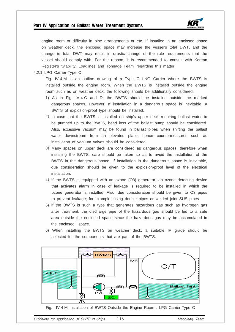
Part IV Application of Ballast Water Treatment Systems
Guideline for Application of BWTS in Ships Machinery Team118
engine room or difficulty in pipe arrangements or etc. If installed in an enclosed space on weather deck, the enclosed space may increase the vessel's total DWT, and the change in total DWT may result in drastic change of the rule requirements that the vessel should comply with. For the reason, it is recommended to consult with Korean Register's 'Stability, Loadlines and Tonnage Team' regarding this matter.
4.2.1 LPG Carrier-Type C Fig. IV-4-M is an outline drawing of a Type C LNG Carrier where the BWTS is
installed outside the engine room. When the BWTS is installed outside the engine room such as on weather deck, the following should be additionally considered.
1) As in Fig. IV-4-C and D, the BWTS should be installed outside the marked dangerous spaces. However, If installation in a dangerous space is inevitable, a BWTS of explosion-proof type should be installed.
2) In case that the BWTS is installed on ship's upper deck requiring ballast water to be pumped up to the BWTS, head loss of the ballast pump should be considered. Also, excessive vacuum may be found in ballast pipes when shifting the ballast water downstream from an elevated place, hence countermeasures such as installation of vacuum valves should be considered.
3) Many spaces on upper deck are considered as dangerous spaces, therefore when installing the BWTS, care should be taken so as to avoid the installation of the BWTS in the dangerous space. If installation in the dangerous space is inevitable, due consideration should be given to the explosion-proof level of the electrical installation.
4) If the BWTS is equipped with an ozone (O3) generator, an ozone detecting device that activates alarm in case of leakage is required to be installed in which the ozone generator is installed. Also, due consideration should be given to O3 pipes to prevent leakage; for example, using double pipes or welded joint SUS pipes.
5) If the BWTS is such a type that generates hazardous gas such as hydrogen gas after treatment, the discharge pipe of the hazardous gas should be led to a safe area outside the enclosed space since the hazardous gas may be accumulated in the enclosed space.
6) When installing the BWTS on weather deck, a suitable IP grade should be selected for the components that are part of the BWTS.
Fig. IV-4-M Installation of BWTS Outside the Engine Room : LPG Carrier-Type C

Part IV Application of Ballast Water Treatment Systems
Guideline for Application of BWTS in Ships Machinery Team119
4.2.2 Gas Carriers Other than LPG Carrier-Type C Fig. IV-4-N, O and P are outline drawings showing installation of the BWTS outside
the engine room of a Type A LPG Carrier, Moss Type LNG Carrier and Membrane Type LNG Carrier, respectively. The ballast tanks adjacent to the cargo containment system of the Type A LPG Carrier, Moss Type LNG Carrier and Membrane Type LNG Carrier are classified as space 1.
1) When installing the BWTS in an enclosed space which is considered as a space, the following should be considered.
a. A BWTS that treats during filling only is not subject to explosion-proof requirements in relation to electrical installation.
b. When installing a drain pipe in a TSU (TRO Sensor Unit) or a GSU (Gas Sensor Unit) which is a part of the BWTS, the drain pipe should led to a safe space outside the enclosed space.
c. When installing air vent pipes on an AVU (Auto Air Vent Unit) which is installed as a part of the BWTS, air pipes should be led to a safe space outside the enclosed space.
d. A sampling pipe which is attached on the ballast discharge pipe should be led outside the enclosed space.
e. If the BWTS is equipped with an ozone (O3) generator, an ozone detection devices that activates alarm in case of leakage is required to be installed in which the ozone generator is installed. Also, due consideration should be given to O3 pipes to prevent leakage; for example, using double pipes or welded joint SUS pipes.
f. If the BWTS is such a type that produces dangerous gas during treatment process, there is a risk of accumulation of dangerous gas in an enclosed space. For the reason, discharge pipes should be led to a safe space outside the enclosed space
Fig. IV-4-N Installation of BWTS Outside the Engine Room : LPG Carrier-Type A
2) In case that the BWTS is installed on ship's upper deck requiring ballast water to be pumped up to the BWTS, head loss of ballast pump should be considered. Also, excessive vacuum may be found in the ballast pipes when shifting the
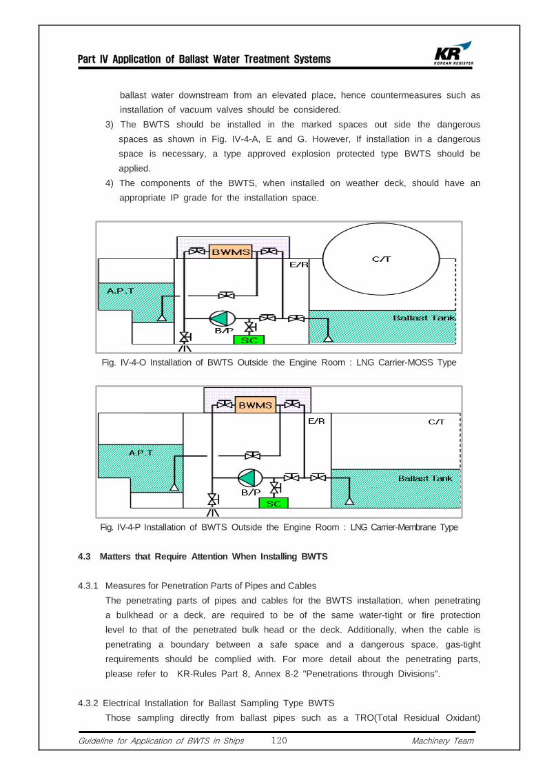
Part IV Application of Ballast Water Treatment Systems
Guideline for Application of BWTS in Ships Machinery Team120
ballast water downstream from an elevated place, hence countermeasures such as installation of vacuum valves should be considered.
3) The BWTS should be installed in the marked spaces out side the dangerous spaces as shown in Fig. IV-4-A, E and G. However, If installation in a dangerous space is necessary, a type approved explosion protected type BWTS should be applied.
4) The components of the BWTS, when installed on weather deck, should have an appropriate IP grade for the installation space.
Fig. IV-4-O Installation of BWTS Outside the Engine Room : LNG Carrier-MOSS Type
Fig. IV-4-P Installation of BWTS Outside the Engine Room : LNG Carrier-Membrane Type
4.3 Matters that Require Attention When Installing BWTS
4.3.1 Measures for Penetration Parts of Pipes and Cables The penetrating parts of pipes and cables for the BWTS installation, when penetrating
a bulkhead or a deck, are required to be of the same water-tight or fire protection level to that of the penetrated bulk head or the deck. Additionally, when the cable is penetrating a boundary between a safe space and a dangerous space, gas-tight requirements should be complied with. For more detail about the penetrating parts, please refer to KR-Rules Part 8, Annex 8-2 "Penetrations through Divisions".
4.3.2 Electrical Installation for Ballast Sampling Type BWTS Those sampling directly from ballast pipes such as a TRO(Total Residual Oxidant)

Part IV Application of Ballast Water Treatment Systems
Guideline for Application of BWTS in Ships Machinery Team121
Sensor Unit or a Gas Sensor Unit should be of approved explosion-proof type even when installed outside the dangerous area. If installed in a safe space, the electrical equipment should be of appropriate type for the area.
4.3.3 Special Considerations for Electrolysis Type BWTS 1) Voltage Drop over Cable Runs In the case of an electrolysis type BWTS, AC 440V (or 220V) is converted into
DC 36V by a rectifier so that a large amount of electric current flows in the circuit, hence the distance of power transmission may be a cause of voltage drop. Therefore, for safe operation, the length of cables should be within manufacturer's recommendation.
2) Composition of Cable Runs Using Bus-bar The electrolysis type BWTS, when its capacity become larger, the required electric
current transmission also become larger resulting in increase of size and number of cables. For the reason, a Bus-bar is often used to reduce the installation space. And in this case, the Bus-bar should be of KR type-approved type and be installed in a trunk whose protection grade is IP54 or above. Installation in dangerous spaces or on weather deck should be avoided. If installed in dangerous spaces, the Bus-bar should be explosion-protection type. Particularly, when penetrating a boundary between a safe area and a dangerous space, fire protection and sealing requirements for penetrating pieces should be complied with. Also, on-board installation methods and the details of penetration parts should be approved by this Society.
5. Particulars
5.1 By-pass Alarm and Recording for BWTS It is stated in the BWM Convention Guidelines G8 4.5.4 that "any by-pass of the BWTS
should activate an alarm, and the by-pass event should be recorded by the control equipment". "By-pass" means filling/discharging of untreated ballast water in/out of ballast tanks without passing the BWTS. Therefore, all valves related to the by-pass event should be of remote controllable type or be equipped with an open/close indicator so that automatic detection and alarm is enabled from BWTS's control device.
5.1.1 Installation in narrow space In general, 2 or more ballast pumps are installed onboard ships, and in most of the
cases, ballast water is filled/discharged in/out of ballast tanks via 2 main ballast pipes on the ballast pump's discharge side. However in small ships, there are cases where the BWTS is installed on only one side of ballast pipes due to limited installation space. In this case, the below design considerations should be taken into account. Fig. IV-2-M is an example where the BWTS is installed on only one side of the main ballast pipes.
1) All pipes related to the by-pass of BWTS should be removed, or an automatic alarm system activated in the event of by-pass should be equipped for all valves
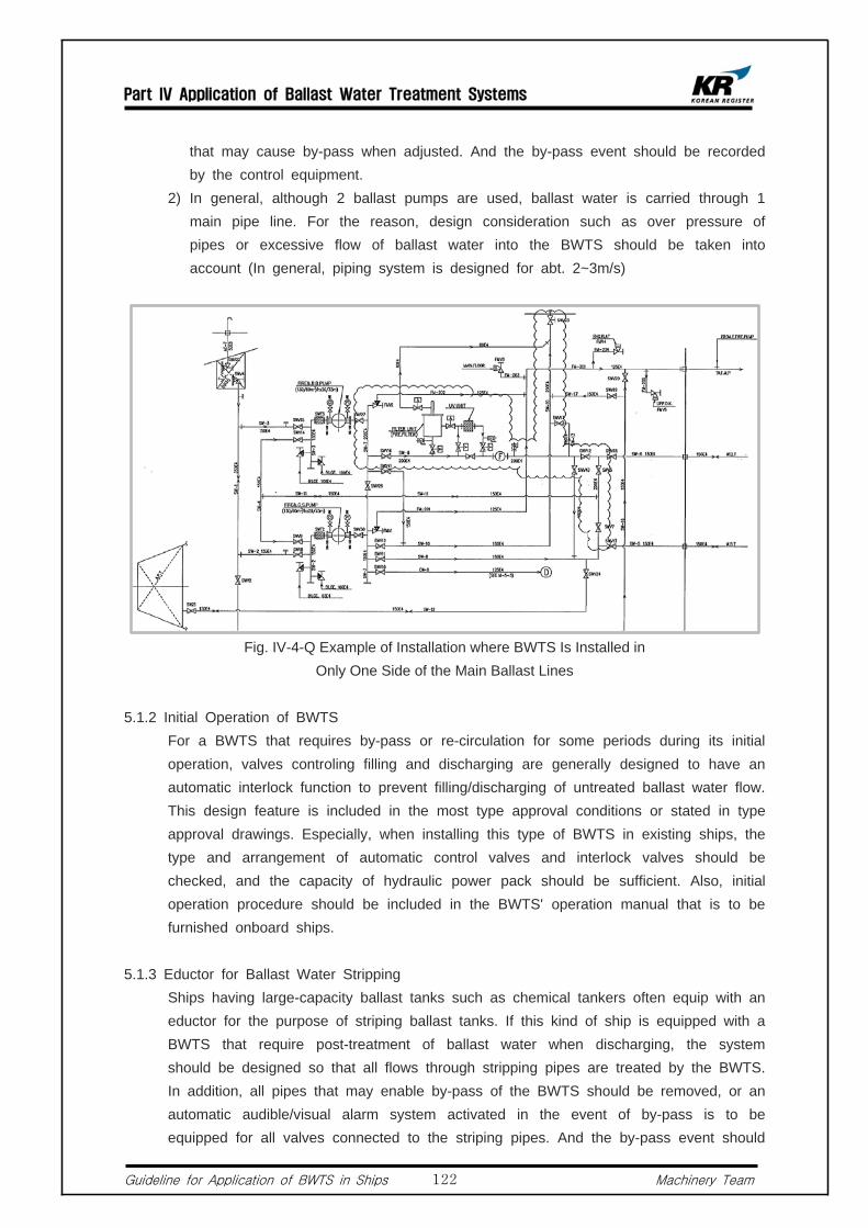
Part IV Application of Ballast Water Treatment Systems
Guideline for Application of BWTS in Ships Machinery Team122
that may cause by-pass when adjusted. And the by-pass event should be recorded by the control equipment.
2) In general, although 2 ballast pumps are used, ballast water is carried through 1 main pipe line. For the reason, design consideration such as over pressure of pipes or excessive flow of ballast water into the BWTS should be taken into account (In general, piping system is designed for abt. 2~3m/s)
Fig. IV-4-Q Example of Installation where BWTS Is Installed in Only One Side of the Main Ballast Lines
5.1.2 Initial Operation of BWTS For a BWTS that requires by-pass or re-circulation for some periods during its initial
operation, valves controling filling and discharging are generally designed to have an automatic interlock function to prevent filling/discharging of untreated ballast water flow. This design feature is included in the most type approval conditions or stated in type approval drawings. Especially, when installing this type of BWTS in existing ships, the type and arrangement of automatic control valves and interlock valves should be checked, and the capacity of hydraulic power pack should be sufficient. Also, initial operation procedure should be included in the BWTS' operation manual that is to be furnished onboard ships.
5.1.3 Eductor for Ballast Water Stripping Ships having large-capacity ballast tanks such as chemical tankers often equip with an
eductor for the purpose of striping ballast tanks. If this kind of ship is equipped with a BWTS that require post-treatment of ballast water when discharging, the system should be designed so that all flows through stripping pipes are treated by the BWTS. In addition, all pipes that may enable by-pass of the BWTS should be removed, or an automatic audible/visual alarm system activated in the event of by-pass is to be equipped for all valves connected to the striping pipes. And the by-pass event should

Part IV Application of Ballast Water Treatment Systems
Guideline for Application of BWTS in Ships Machinery Team123
be recorded by the control equipment.
5.1.4 Retroactive Application to Existing Ships In most existing ships, 2 or more ballast pumps are installed, and their discharge
outlets are connected to ballast tanks through 2 main ballast pipes. However, in small ships, there are cases where the BWTS is connected to only 1 of the main ballast pipes due to limited installation space. In such cases, the following should be considered.
1) All pipes related to the by-pass of BWTS should be removed or, all valves related to the by-pass should comply with the requirements described in above 5.1.
2) In general, although 2 ballast pumps are used, ballast water is carried through 1 main pipe line. For the reason, design consideration such as over pressure of pipes or excessive flow of ballast water into the BWTS should be taken into account.
5.2 Filling and Discharging by Gravity
5.2.1 A BWTS that Treats During Ballast Water Intake Only 1) Ships designed to discharge ballast water by gravity such as large LPG carriers or
LNG carriers may discharge the ballast water by gravity if a BWTS that treats ballast water during filling only is installed. FIg. IV-4-R shows an example of a ship capable of discharging ballast water by gravity.
2) There should be no ingress of untreated ballast water into ballast tanks during ballast intake. For the reason, check valves should be used in the discharge section. If stop valves are used, requirements in above 5.1 should be met since by pass may occur at the stop valve.
5.2.2 A BWTS Having an Additional Treatment Stage During De-ballasting 1) Ships equipped with a BWTS that treats ballast water not only during filling
process but also during discharging process are required to close the valves that are attached to the sea chests at all time. Also, the valves should comply with the requirements of above 5.1. as by-pass may occur at the valves.
2) Above 1) should be considered, in particular, if an overflow pipe for the ballast exchange is installed in an existing ship for the purpose of complying with the BWM Convention D1 (Ballast Water Exchange Method).

Part IV Application of Ballast Water Treatment Systems
Guideline for Application of BWTS in Ships Machinery Team124
Fig. IV-4-R Ballast Water Discharge by Gravity
5.3 When Using Ballast Pump for Other Purposes For ships whose fire pumps also serve as a ballast pump, if the BWTS is of
remote-controllable type, the valves in the in/outlet of the fire pumps should also be remote-controllable. The same should be applied when the bilge pumps serve as the ballast pump.
5.4 Ships having a KR Class Notation of UMA or above Ships registered to this Society and having a Class Notation of UMA or above (UMA,
UMA1, UMA2, UMA3) are required to equip with a remote-controllable fire pump according to KR-Rules Pt 9, Ch 3. Hence, those using fire pumps also for ballasting should take above into account.
5.5 Ships Having a KR Class Notation of UMA1 or Above Ships registered to this Society and having a Class Notation of UMA1 or above (UMA,
UMA1, UMA2, UMA3) are, according to KR-Rules Pt 9, Ch 3, 502.1, required to equip with a system that can control ballasting remotely. Hence, for ships with UMA1 or above and having a BWTS installed onboard, all valves related to the filling/discharging of ballast water or operation of the BWTS should be remote controllable.
5.6 Fresh Water Tank When a fresh water tank is served as a ballast tank, chemicals contained in fresh water
may potentially be discharged. In this regards, the application of the BWM Convention to portable water is under discussion at IMO.
5.7 Electric Consumption and Composition of Electric Circuit Electric load analysis should be carried out and the result should be submitted to this
Society to make sure that the electric power installed on-board is sufficient to cover the increased electric consumption. Also, electrical components of the BWTS should be protected from overloading or short-circuit.
5.8 Fire Integrity for Areas Where BWTS Is Installed. The BWTS can also be installed in a space inside the deckhouse. In this case, the
said space is defined, according to SOLAS Reg. II-2/3 regulation, as a machinery space

Part IV Application of Ballast Water Treatment Systems
Guideline for Application of BWTS in Ships Machinery Team125
or service space. For the reason, bulkheads or decks of living area adjacent to the machinery space or service space are required to have fire integrity of A-0 or above according to SOLAS Reg. II-2/9 regulation.
5.9 Modification of Ballast Tanks According to the BWM Convention Annex A-1, Reg.5, an existing ship carrying out
major conversion is considered as a new ship. "Major conversion" means a conversion of a ship :
1) which changes its ballast water carrying capacity by 15% or greater, or 2) which changes the ship type, or 3) which, in the opinion of the Administration, is projected to prolong its life by ten
years or more, or 4) which results in modification to its ballast water system other than component
replacement-in-kind.
5.10 Control, Monitoring and Alarm of BWTS The BWM Convention Guidance8, Chapter4, describes the requirements of control
equipment and monitoring & alarm equipment.
5.10.1 Control Device and Monitoring and Alarm Device 1) The injection amount or the injection level of BWTS that is required for the
treatment of ballast water should be controlled automatically. The control equipment should be capable of continuous self-monitoring during operation, and operation related items should be automatically monitored and control.
2) Malfunctions or errors occurring in the system should be monitored. And should this kind of problem affects operation of the BWTS, audible/visual alarm should be activated in all areas in which the ballast water treatment process is regulated.
5.10.2 Operation and Control 1) Operation and control of the BWTS should be simple and effective, and all control
should be remote controllable, as far as practicable. However, this does not necessarily mean the automation of all valves related to the BWTS, but easy and effective manual operation is acceptable, except those that may cause BWTS's malfunction. In this case, it is recommended that guidelines for the handling procedure of manual valves when filling/discharging ballast water and piping diagrams indicating related valves should be posted in all control areas.
2) Ships registered to this Society and having a notation of UMA1 or above are required that all valves related to the operation of BWTS and ballast pumps should be remote controllable, and such a system should be interconnected with the existing remote control device of the ballast pumps for automatic control.
5.10.3 By-pass and Override 1) Ships equipped with a BWTS should install a means of by-pass or override for

Part IV Application of Ballast Water Treatment Systems
Guideline for Application of BWTS in Ships Machinery Team126
the protection of the ships or their crews in case of emergency. Also, in case of by-pass, audible/visual alarm should be activated automatically by the monitoring system and the by-pass event should be recorded in the control system.
2) In case of existing ships, the BWTS is generally to be installed in one side of the ballast lines. For the reason, the usage of other ballast lines should be monitored. In relation to this, suppliers should submit the list of situations where by-pass may occur, considering the ships's ballast piping arrangement, for review.
Part V Ballast Water Sampling
Guideline for Application of BWTS in Ships Machinery Team127
Part V Ballast Water Sampling
General
1.1 According to the regulation A-2 of the BWM Convention, discharge of ballast water should only be conducted by ballast water management in accordance with the provision of the annex to the convention. Also, article 9 of the BWM Convention provides that a ship to which the convention applies may, in any port or offshore terminal of another parties, be subject to inspection by officers duly authorized by that party for the purpose of determining whether the ship is in compliance with the convention.
1.2 Sampling requirements for complying with regulations D-1 and D-2 of the Convention will differ as these two regulations have significantly different parameters. In this part of the guidelines, location of sampling points and installation of sampling devices in compliance with regulations D-1 and D-2 of the convention will be discussed.
1.3 Although the Convention contains no requirement for provisions of sampling points, the Guidelines for approval of ballast water management systems (G8) adopted by resolution MEPC.174(58) do expressly call for the provision of sampling facilities, not only for the purpose of type approval, but also for the purpose of the Draft Guidelines for Ballast Water Sampling (G2).
1.4 Currently, there is much discussion on ballast sampling and approval methods at IMO,
and related guidelines will be finalized later.
1.5 Definitions 1) "Sampling point" means that place in the ballast water piping where the sample is
taken. 2) "Sampling Facilities" mean the equipment installed to take the sample.
Requirements for Ballast Water Sampling
2.1 Requirements for Compliance with the Ballast Water Exchange Standard (Regulation D-1) Ballast water sampling from ballast tanks may be taken via sounding or air pipes and
manholes by using pumps, sampling bottles or other water containers. Sampling may also be taken from the discharge line.
2.2 Requirements for Compliance with the Ballast Water Exchange Standard (Regulation D-2)
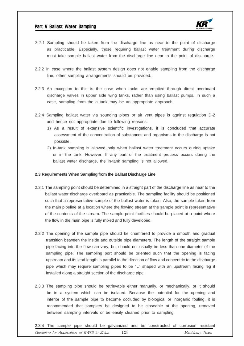
Part V Ballast Water Sampling
Guideline for Application of BWTS in Ships Machinery Team128
2.2.1 Sampling should be taken from the discharge line as near to the point of discharge as practicable. Especially, those requiring ballast water treatment during discharge must take sample ballast water from the discharge line near to the point of discharge.
2.2.2 In case where the ballast system design does not enable sampling from the discharge line, other sampling arrangements should be provided.
2.2.3 An exception to this is the case when tanks are emptied through direct overboard discharge valves in upper side wing tanks, rather than using ballast pumps. In such a case, sampling from the a tank may be an appropriate approach.
2.2.4 Sampling ballast water via sounding pipes or air vent pipes is against regulation D-2
and hence not appropriate due to following reasons. 1) As a result of extensive scientific investigations, it is concluded that accurate
assessment of the concentration of substances and organisms in the discharge is not possible.
2) In-tank sampling is allowed only when ballast water treatment occurs during uptake or in the tank. However, If any part of the treatment process occurs during the ballast water discharge, the in-tank sampling is not allowed.
2.3 Requirements When Sampling from the Ballast Discharge Line
2.3.1 The sampling point should be determined in a straight part of the discharge line as near to the ballast water discharge overboard as practicable. The sampling facility should be positioned such that a representative sample of the ballast water is taken. Also, the sample taken from the main pipeline at a location where the flowing stream at the sample point is representative of the contents of the stream. The sample point facilities should be placed at a point where the flow in the main pipe is fully mixed and fully developed.
2.3.2 The opening of the sample pipe should be chamfered to provide a smooth and gradual transition between the inside and outside pipe diameters. The length of the straight sample pipe facing into the flow can vary, but should not usually be less than one diameter of the sampling pipe. The sampling port should be oriented such that the opening is facing upstream and its lead length is parallel to the direction of flow and concentric to the discharge pipe which may require sampling pipes to be "L" shaped with an upstream facing leg if installed along a straight section of the discharge pipe.
2.3.3 The sampling pipe should be retrievable either manually, or mechanically, or it should be in a system which can be isolated. Because the potential for the opening and interior of the sample pipe to become occluded by biological or inorganic fouling, it is recommended that samplers be designed to be closeable at the opening, removed between sampling intervals or be easily cleaned prior to sampling.
2.3.4 The sample pipe should be galvanized and be constructed of corrosion resistant
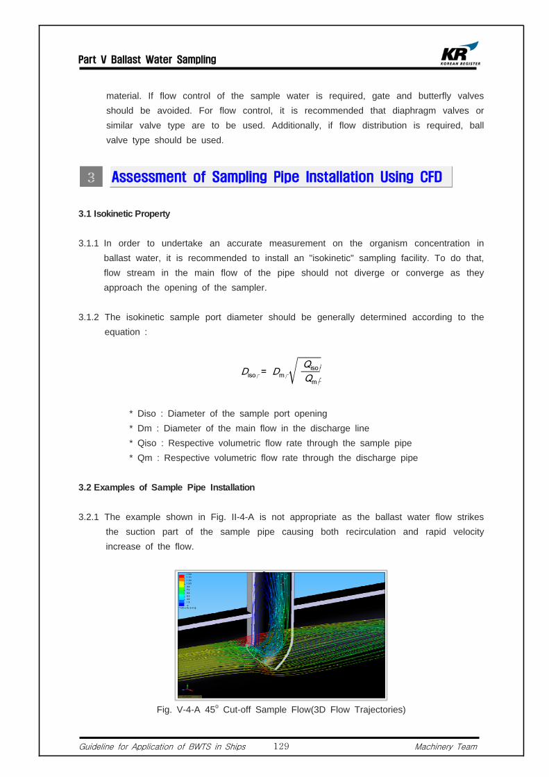
Part V Ballast Water Sampling
Guideline for Application of BWTS in Ships Machinery Team129
material. If flow control of the sample water is required, gate and butterfly valves should be avoided. For flow control, it is recommended that diaphragm valves or similar valve type are to be used. Additionally, if flow distribution is required, ball valve type should be used.
Assessment of Sampling Pipe Installation Using CFD
3.1 Isokinetic Property
3.1.1 In order to undertake an accurate measurement on the organism concentration in ballast water, it is recommended to install an "isokinetic" sampling facility. To do that, flow stream in the main flow of the pipe should not diverge or converge as they approach the opening of the sampler.
3.1.2 The isokinetic sample port diameter should be generally determined according to the equation :
Diso� = Dm� Qiso��
Qm��
* Diso : Diameter of the sample port opening * Dm : Diameter of the main flow in the discharge line * Qiso : Respective volumetric flow rate through the sample pipe * Qm : Respective volumetric flow rate through the discharge pipe
3.2 Examples of Sample Pipe Installation
3.2.1 The example shown in Fig. II-4-A is not appropriate as the ballast water flow strikes the suction part of the sample pipe causing both recirculation and rapid velocity increase of the flow.
Fig. V-4-A 45o Cut-off Sample Flow(3D Flow Trajectories)
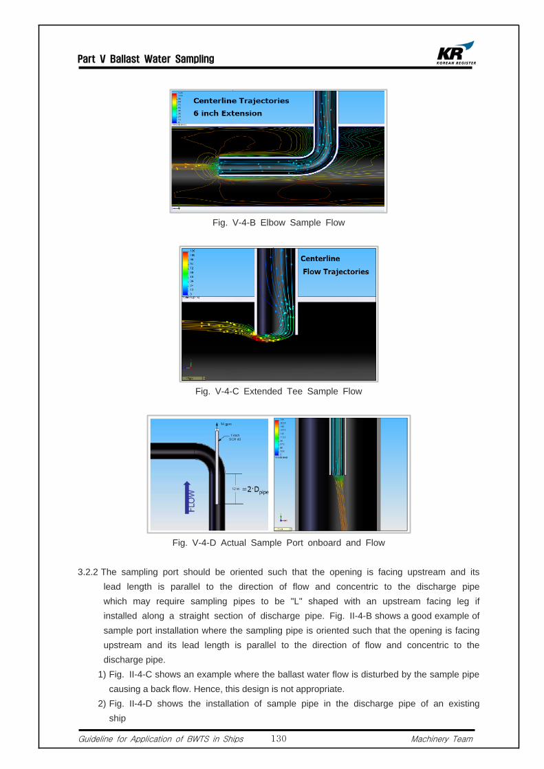
Part V Ballast Water Sampling
Guideline for Application of BWTS in Ships Machinery Team130
Fig. V-4-B Elbow Sample Flow
Fig. V-4-C Extended Tee Sample Flow
Fig. V-4-D Actual Sample Port onboard and Flow
3.2.2 The sampling port should be oriented such that the opening is facing upstream and its lead length is parallel to the direction of flow and concentric to the discharge pipe which may require sampling pipes to be "L" shaped with an upstream facing leg if installed along a straight section of discharge pipe. Fig. II-4-B shows a good example of sample port installation where the sampling pipe is oriented such that the opening is facing upstream and its lead length is parallel to the direction of flow and concentric to the discharge pipe.
1) Fig. II-4-C shows an example where the ballast water flow is disturbed by the sample pipe causing a back flow. Hence, this design is not appropriate.
2) Fig. II-4-D shows the installation of sample pipe in the discharge pipe of an existing ship

Part Vi Approval of Ballast Water Treatment Systems
Guideline for Application of BWTS in Ships Machinery Team131
Part VI Approval of Ballast Water Treatment Systems
Requirements for Ballast Water Treatment Systems
1.1 Ballast Water Treatment Systems
1.1.1 Outline of BWTS 1) The BWTS should be assessed whether it meets the standard of Regulation D-2 (See Fig.
II-2-C) via a test. According to Part 2 and 3 of the Annex to the BWM Convention Guidelines (G8), a land-based test or on-board test should be conducted and the BWTS should be certified for a type approval by the Administration.
2) Ships subject to the BWM Convention should install a type approved BWTS according to the application schedule that varies by ships tonnage (see Fig. II-2-C).
1.1.2 Definitions 1) Shipboard Testing : is a full-scale test of a complete BWTS carried out on board a ship
according to Part 2 of the annex to the guidelines of the BWTS Convention, to confirm that the system meets the standards set by Regulation D-2 of the Convention.
2) Land-based Testing : is a test of a BWTS carried out in a laboratory, equipment factory or pilot plant including a moored test barge or test ship, according to Part 2 and 3 of the Annex to the G8.
3) Control Equipment : refers to the installed equipment required to operate and control the Ballast Water Treatment Equipment.
4) Monitoring Equipment : refers to the equipment installed for the assessment of the effective operation of the Ballast Water Treatment Equipment.
5) Treatment Rated Capacity(TRC) : is the maximum continuous capacity expressed in cubic meters per hour for which the BWTS is type approved. It states the amount of ballast water that can be treated per unit time by the BWTS to meet the standard in Regulation D-2 of the Convention.
1.2 General Requirements for BWTS
1.2.1 Alarm Device and Automation Arrangements 1) Alarm Device
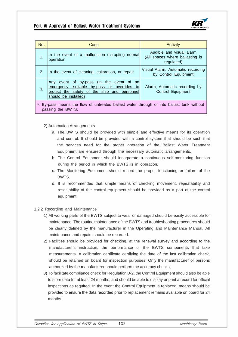
Part Vi Approval of Ballast Water Treatment Systems
Guideline for Application of BWTS in Ships Machinery Team132
No. Case Activity
1. In the event of a malfunction disrupting normal operation
Audible and visual alarm(All spaces where ballasting is
regulated)
2. In the event of cleaning, calibration, or repair Visual Alarm, Automatic recording by Control Equipment
3.
Any event of by-pass (in the event of an emergency, suitable by-pass or overrides to protect the safety of the ship and personnel should be installed)
Alarm, Automatic recording by Control Equipment
※ By-pass means the flow of untreated ballast water through or into ballast tank without passing the BWTS.
2) Automation Arrangements a. The BWTS should be provided with simple and effective means for its operation
and control. It should be provided with a control system that should be such that the services need for the proper operation of the Ballast Water Treatment Equipment are ensured through the necessary automatic arrangements.
b. The Control Equipment should incorporate a continuous self-monitoring function during the period in which the BWTS is in operation.
c. The Monitoring Equipment should record the proper functioning or failure of the BWTS.
d. It is recommended that simple means of checking movement, repeatability and reset ability of the control equipment should be provided as a part of the control equipment.
1.2.2 Recording and Maintenance 1) All working parts of the BWTS subject to wear or damaged should be easily accessible for
maintenance. The routine maintenance of the BWTS and troubleshooting procedures should be clearly defined by the manufacturer in the Operating and Maintenance Manual. All maintenance and repairs should be recorded.
2) Facilities should be provided for checking, at the renewal survey and according to the manufacturer's instruction, the performance of the BWTS components that take measurements. A calibration certificate certifying the date of the last calibration check, should be retained on board for inspection purposes. Only the manufacturer or persons authorized by the manufacturer should perform the accuracy checks.
3) To facilitate compliance check for Regulation B-2, the Control Equipment should also be able to store data for at least 24 months, and should be able to display or print a record for official inspections as required. In the event the Control Equipment is replaced, means should be provided to ensure the data recorded prior to replacement remains available on board for 24 months.

Part Vi Approval of Ballast Water Treatment Systems
Guideline for Application of BWTS in Ships Machinery Team133
1.3 General Requirements for BWTS
1.3.1 Control Equipment 1) The BWTS should be provided with a control system that should be such that the services
need for the proper operation of the BWTS are ensured through necessary automatic arrangements.
1.3.2 Dangerous Spaces 1) The Ballast Water Treatment Equipment should, if intended to be fitted in locations
where flammable atmospheres may be present, comply with the relevant safety regulations for such spaces.
2) Any electrical equipment that is part of the BWTS should be based in a non-hazardous area, or should be certified by the Administration as safe for use in a hazardous area. Any moving parts, which are fitted in hazardous areas, should be arranged so as to avoid the formation of static electricity.
1.4 Cautions When Applying in Existing Ships
1.4.1 Electric Consumption and Main Power Capacity 1) In prior to the installation BWTS, it is to be checked whether the main power is
sufficient to cover the electrical consumption of the BWTS. For the reason, an electric load table including the load of BWTS should be submitted to this Society for review.
2) It is to be checked whether the electric consumption of BWTS has been reflected in the electric load table. The electric load table is calculated, as shown in Fig. V-1.4.1-A, according to ship's operating conditions (normal sea going, at port in/out, at cargo handling, and at harbor). And because the BWTS may be operated while loading/unloading cargoes, the electric consumption required for loading/unloading conditions should be included in the calculation. Therefore, an additional generator may be considered, if required.
3) If the capacity of additionally installed generator is above 100KVA, the generator is subject to drawing approval and materials and equipment inspection.
4) The larger the ship, the larger the ballast tanks, accordingly, the electric consumption of BWTS become larger. For the reason, electric power should be checked in the electric load table, especially in case of large ships.
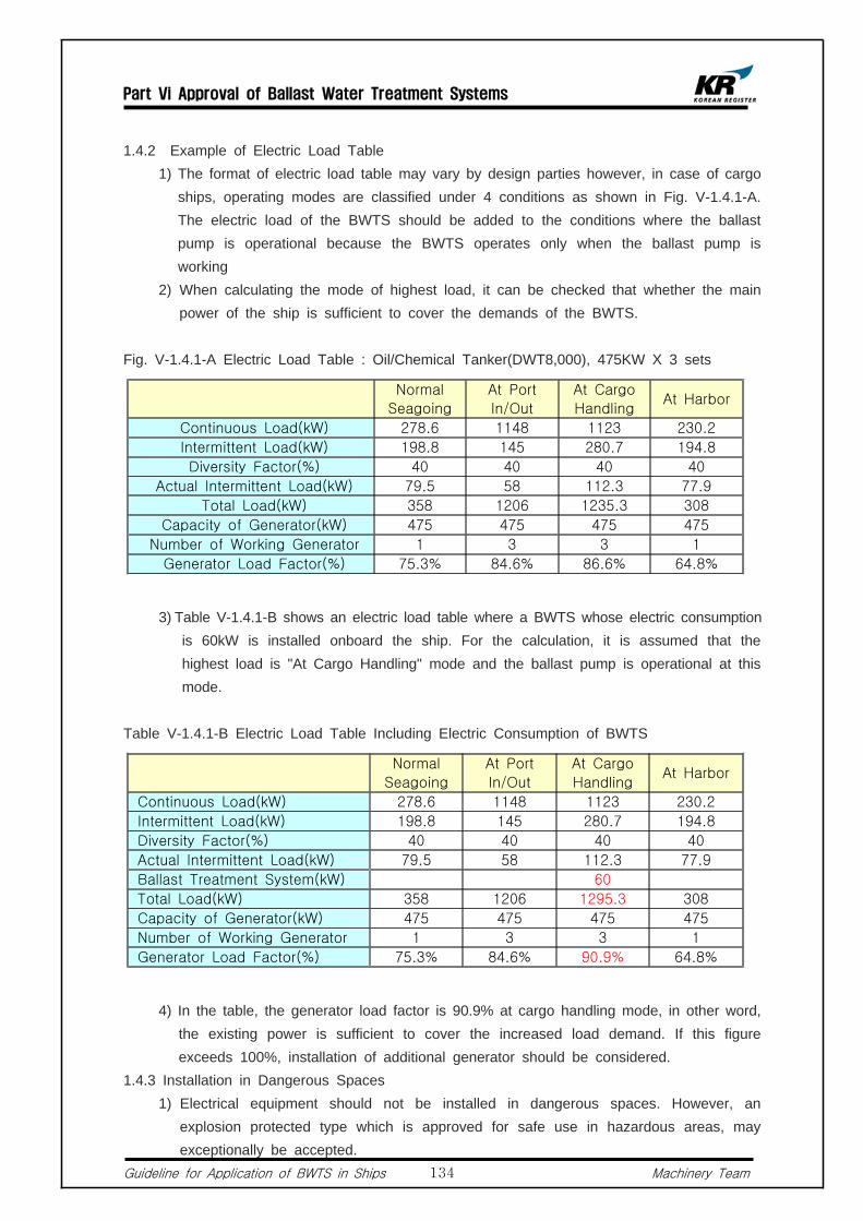
Part Vi Approval of Ballast Water Treatment Systems
Guideline for Application of BWTS in Ships Machinery Team134
1.4.2 Example of Electric Load Table 1) The format of electric load table may vary by design parties however, in case of cargo
ships, operating modes are classified under 4 conditions as shown in Fig. V-1.4.1-A. The electric load of the BWTS should be added to the conditions where the ballast pump is operational because the BWTS operates only when the ballast pump is working
2) When calculating the mode of highest load, it can be checked that whether the main power of the ship is sufficient to cover the demands of the BWTS.
Fig. V-1.4.1-A Electric Load Table : Oil/Chemical Tanker(DWT8,000), 475KW X 3 sets
Normal
Seagoing
At Port
In/Out
At Cargo
HandlingAt Harbor
Continuous Load(kW) 278.6 1148 1123 230.2
Intermittent Load(kW) 198.8 145 280.7 194.8
Diversity Factor(%) 40 40 40 40
Actual Intermittent Load(kW) 79.5 58 112.3 77.9
Total Load(kW) 358 1206 1235.3 308
Capacity of Generator(kW) 475 475 475 475
Number of Working Generator 1 3 3 1
Generator Load Factor(%) 75.3% 84.6% 86.6% 64.8%
3) Table V-1.4.1-B shows an electric load table where a BWTS whose electric consumption is 60kW is installed onboard the ship. For the calculation, it is assumed that the highest load is "At Cargo Handling" mode and the ballast pump is operational at this mode.
Table V-1.4.1-B Electric Load Table Including Electric Consumption of BWTS
Normal
Seagoing
At Port
In/Out
At Cargo
HandlingAt Harbor
Continuous Load(kW) 278.6 1148 1123 230.2
Intermittent Load(kW) 198.8 145 280.7 194.8
Diversity Factor(%) 40 40 40 40
Actual Intermittent Load(kW) 79.5 58 112.3 77.9
Ballast Treatment System(kW) 60
Total Load(kW) 358 1206 1295.3 308
Capacity of Generator(kW) 475 475 475 475
Number of Working Generator 1 3 3 1
Generator Load Factor(%) 75.3% 84.6% 90.9% 64.8%
4) In the table, the generator load factor is 90.9% at cargo handling mode, in other word, the existing power is sufficient to cover the increased load demand. If this figure exceeds 100%, installation of additional generator should be considered.
1.4.3 Installation in Dangerous Spaces 1) Electrical equipment should not be installed in dangerous spaces. However, an
explosion protected type which is approved for safe use in hazardous areas, may exceptionally be accepted.
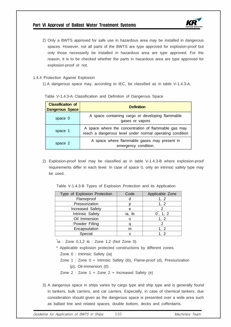
Part Vi Approval of Ballast Water Treatment Systems
Guideline for Application of BWTS in Ships Machinery Team135
2) Only a BWTS approved for safe use in hazardous area may be installed in dangerous spaces. However, not all parts of the BWTS are type approved for explosion-proof but only those necessarily be installed in hazardous area are type approved. For the reason, it is to be checked whether the parts in hazardous area are type approved for explosion-proof or not.
1.4.4 Protection Against Explosion 1) A dangerous space may, according to IEC, be classified as in table V-1.4.3-A. Table V-1.4.3-A Classification and Definition of Dangerous Space
Classificaiton of Dangerous Space Definition
space 0 A space containing cargo or developing flammable gases or vapors
space 1 A space where the concentration of flammable gas may reach a dangerous level under normal operating condition
space 2 A space where flammable gases may present in emergency condition.
2) Explosion-proof level may be classified as in table V-1.4.3-B where explosion-proof requirements differ in each level. In case of space 0, only an intrinsic safety type may be used.
Table V-1.4.3-B Types of Explosion Protection and its Application
Type of Explosion Protection Code Applicable ZoneFlameproof d 1, 2
Pressurization p 1, 2Increased Safety e 2Intrinsic Safety ia, ib 0*, 1, 2Oil Immersion o 1, 2Powder Filling q 2Encapsulation m 1, 2
Special s 1, 2 *ia : Zone 0,1,2 ib : Zone 1,2 (Not Zone 0)
* Applicable explosion protected constructions by different zones.Zone 0 : Intrinsic Safety (ia)Zone 1 : Zone 0 + Intrinsic Safety (ib), Flame-proof (d), Pressurization (p), Oil-Immersion (0) Zone 2 : Zone 1 + Zone 2 + Increased Safety (e)
3) A dangerous space in ships varies by cargo type and ship type and is generally found in tankers, bulk carriers, and car carriers. Especially, in case of chemical tankers, due consideration should given as the dangerous space is presented over a wide area such as ballast line and related spaces, double bottom, decks and cofferdams.

Part Vi Approval of Ballast Water Treatment Systems
Guideline for Application of BWTS in Ships Machinery Team136
Drawing Approval and On-board Inspection
2.1 Drawing Approval in Prior to BWTS Installation Onboard Ships
2.1.1 A list of drawings to be approved by Machinery Team for the installation of BWTS in new ships is as follows. And the BWTS should be type-approved by the Administration.
1) Supplier's detail drawings (ship owner or manufacturer) - should include followings : a. Installation drawings of the BWTS b. Sampling faculties c. Pumping and piping arrangements 2) A generic operation and technical manual (Ship owner or manufacturer) - should include
followings : a. A description of major components and the operation and maintenance of the
BWTS; b. Normal operation procedures; c. Procedures for the discharge of untreated water in the event of malfunction of the
Ballast Water Treatment Equipment, maintenance procedures, and emergency action necessary for securing the ship;
d. A technical section of the manual including adequate information (description and diagrammatic drawings of the monitoring system and electrical/ electronic wiring diagrams) to enable faultfinding. This section should include instructions for keeping a maintenance record;
e. Requirements for the location and mounting of components, arrangements for maintaining the integrity of the boundary between safe and hazardous spaces
f. A technical installation specification defining the arrangement of the sample piping. 3) A description of BWTS side streams (e.g., filtered materials, centrifugal concentrate, waste
or residual chemicals) including a description of the actions planned to properly manage and dispose of such wastes (ship owner or manufacturer);
4) A recommended test and checkout procedure specific to the BWTS (ship owner or manufacturer);
a. Including all the checks carried out in a functional test 5) Machinery arrangements in relation to BWTS installation (ship yard) 6) Machinery arrangements in relation to BWTS installation (ship yard) 7) General arrangement for electrical systems (ship yard) 8) Wiring diagram for power systems (ship yard) 9) Investigation table of electrical load analysis (ship yard) 2.1.2 When installing a BWTS in existing ships, the list of drawings to be approved by
Machinery Team is follows. And the BWTS should be type-approved by the Administration.
1) Supplier's detail drawings (ship owner or manufacturer) - should include followings :
Part Vi Approval of Ballast Water Treatment Systems
Guideline for Application of BWTS in Ships Machinery Team137
a. Installation drawings of the BWTS b. Sampling faculties c. Pumping and piping arrangements 2) A generic operation and technical manual (Ship owner or manufacturer)- should include the
followings : a. A description of major components and the operation and maintenance of the
BWTS; b. Normal operation procedures; c. Procedures for the discharge of untreated water in the event of malfunction of the
Ballast Water Treatment Equipment, maintenance procedures, and emergency action necessary for securing the ship;
d. A technical section of the manual including adequate information (description and diagrammatic drawings of the monitoring system and electrical/ electronic wiring diagrams) to enable faultfinding. This section should include instructions for keeping a maintenance record;
e. Requirements for the location and mounting of components, arrangements for maintaining the integrity of the boundary between safe and hazardous spaces
f. A technical installation specification defining the arrangement of the sample piping. 3) A description of BWTS side streams (e.g., filtered materials, centrifugal concentrate, waste
or residual chemicals) including a description of the actions planned to properly manage and dispose of such wastes (ship owner or manufacturer);
4) A recommended test and checkout procedure specific to the BWTS (ship owner or manufacturer);
a. Including all the checks carried out in a functional test 5) Machinery arrangements in relation to BWTS installation (ship yard) 6) Machinery arrangements in relation to BWTS installation (ship yard) 7) General arrangement for electrical systems (ship yard) 8) Wiring diagram for power systems (ship yard) 9) Investigation table of electrical load analysis (ship yard)2.1.3 An additional requirement for BWTS that make use of active substances (G9) 1) Toxicity tests should include assessments of the effects of hold time following
treatment, and dilution, on the toxicity. Toxicity tests of the treated water should be conducted in accordance with procedures in G9 and its result should provided together with the test manual.
2.2 Materials and Equipment Inspection
2.2.1 Type Approval by Korean Government 1) Considering the fact that Korean Resister has been participating in the part of the final
drawing approvals and feasibility tests as a Recognized Organization for Feasibility Test and been provided with relevant drawings and information, a type approval by this Society will be exempted. However, drawing approval and material and equipment inspection for registered ships should be conducted and a certificate will be issued.
Part Vi Approval of Ballast Water Treatment Systems
Guideline for Application of BWTS in Ships Machinery Team138
2.2.2 Type Approval by Non-Korean Government (including those type-approved by RO of the country)
1) Considering the fact that Korean Resister has not been able to participate in the process of final approval and difficulties in checking conformity between products and submitted drawings, for those type approval by this Society, a certificate will be issued after drawing approval and materials and equipment inspection.
2.2.3 Inspection of Materials and Equipment for a Single Product 1) Inspection will be carried out by a KR branch office covering the location of manufacturers. 2) Items for inspection a. Inspection of structure and exterior according to the drawings and specifications.
And checking labeling requirements. b. Hydro test, if applicable c. Insulation resistance test/high voltage test for Control Panel/Starting Panel d. Performance Test (excluding biological tests)
2.3 Inspection On-board Ships
2.3.1 List of Drawings to be kept Aboard a Ship 1) Above mentioned KR-approved drawings and below lists documents should be kept
on-board ships. a. A copy of the type approval certificate of BWTS b. A statement from the Administration, or from a laboratory authorized by the
Administration, to confirm that the electrical and electronic components of the BWTS have been type-tested in accordance with the specifications for environmental testing.
c. Specifications for Installation d. Installation commissioning procedures e. Initial calibration procedures2.3.2 The followings are to be verified that : 1) the BWTS installation has been carried out in accordance with the technical installation
specification. 2) the BWTS is in conformity with the Type Approval Certificate of BWTS issued by the
Administration or its representative; 3) the installation of the complete BWTS has been carried out in accordance with the
manufacturer's equipment specification; 4) any operational inlets and outlets are located in the positions indicated on the drawing of the
pumping and piping arrangements;

Part Vi Approval of Ballast Water Treatment Systems
Guideline for Application of BWTS in Ships Machinery Team139
5) the workmanship of the installation is satisfactory and, in particular, that any bulkhead penetrations or penetrations of the ballast system piping are to the relevant approved standards;
6) the control and monitoring equipment operates correctly and be able to store records for 24 months, and the records are viewable and printable when required for official survey.
7) the BWTS is provided with sampling facilities so arranged in order to collect representative samples of the ship's ballast water.
Application of Local Regulations (Korea)
3.1 Inspection of Ships
3.1.1 Drawing Approval 1) Ship owners wishing to install a BWTS on-board ships are required to receive an approval
from the Ministry of Land, Transport, Maritime Affairs 2) Ship owners are required to furnish an approved drawing on-board ships.
3.1.2 Renewal Inspection 1) Ships having a BWTS installed onboard and operating it for the first time for normal
seagoing, or whose renewal survey period (5 years) has been expired are subject to a renewal survey.
2) A certificate for the inspection of BWTS should be provided for those passed the renewal survey.
3) Ship owners are required to furnish a certificate of the survey on-board the ship.

Appendix
A. Hazardous Areas and Requirements for Electrical Installation in
Each Ship Type
B. Requirements for Ballast Water Treatment in California
C. Requirements for Ballast Water Treatment in New York
D. Means to Verify Ballast Water Treatment Systems for Ships
Entering Australian Ports
E. Questionnaires [BWTS Manufacturers]
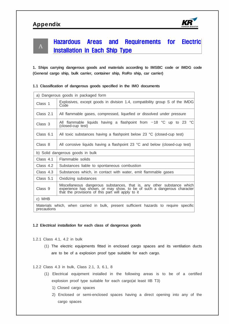
Appendix
Hazardous Areas and Requirements for Electric
Installation in Each Ship Type
1. Ships carrying dangerous goods and materials according to IMSBC code or IMDG code (General cargo ship, bulk carrier, container ship, RoRo ship, car carrier)
1.1 Classification of dangerous goods specified in the IMO documents
a) Dangerous goods in packaged form
Class 1 Explosives, except goods in division 1.4, compatibility group S of the IMDG Code
Class 2.1 All flammable gases, compressed, liquefied or dissolved under pressure
Class 3 All flammable liquids having a flashpoint from −18 °C up to 23 °C(closed-cup test)
Class 6.1 All toxic substances having a flashpoint below 23 °C (closed-cup test)
Class 8 All corrosive liquids having a flashpoint 23 °C and below (closed-cup test)
b) Solid dangerous goods in bulk
Class 4.1 Flammable solidsClass 4.2 Substances liable to spontaneous combustion
Class 4.3 Substances which, in contact with water, emit flammable gasesClass 5.1 Oxidizing substances
Class 9Miscellaneous dangerous substances, that is, any other substance which experience has shown, or may show, to be of such a dangerous character that the provisions of this part will apply to it
c) MHB
Materials which, when carried in bulk, present sufficient hazards to require specific precautions
1.2 Electrical installation for each class of dangerous goods
1.2.1 Class 4.1, 4.2 in bulk
(1) The electric equipments fitted in enclosed cargo spaces and its ventilation ducts
are to be of a explosion proof type suitable for each cargo.
1.2.2 Class 4.3 in bulk, Class 2.1, 3, 6.1, 8
(1) Electrical equipment installed in the following areas is to be of a certified
explosion proof type suitable for each cargo(at least IIB T3)
1) Closed cargo spaces
2) Enclosed or semi-enclosed spaces having a direct opening into any of the
cargo spaces

Appendix
3) The ventilation ducts of cargo spaces and areas within 3m of any exhaust
ventilation outlet of cargo spaces
(2) Where equipments such as flanges, valves, pumps, etc are installed in the
enclosed spaces(e.g. pipe space, duck keel) containing the bilge pipes for cargo
spaces, the following types of electrical equipments are accepted to be installed
in the enclosed space unless provided with a minimum overpressure of 25 Pa
according to IEC60092-506.
1) Electrical equipment with the type of protection as permitted in cargo spaces,
or
2) Equipment of protection class Exn, or
3) Electrical equipment which ensures absence of sparks or arcs during normal
operation and whose surface does not reach unacceptably high temperature
1.3 Protection type of electric equipment for solid bulk cargoes
Table 1 Protection type of electric equipments
2. Hazardous areas in tankers carrying flammable liquids having a flashpoint below 60℃
(crude Oil, oil products, chemical products)
In case of tankers carrying flammable liquids not exceeding flashpoint 60℃, hazardous area
is classified from zone 0 to zone 2 according to IEC 60092-502 4.2 and the types of

Appendix
allowable electrical equipments vary depending on the class of hazardous area.
2.1 Zone 0
(1) Cargo tanks
(2) Cargo ventilation pipes and ducts
(3) Cargo pipes
2.2 Zone 1
(1) Spaces adjacent to cargo tanks such as cofferdams, ballast tanks, etc
Fig. 1 Example of hazardous area
(2) Enclosed or semi-enclosed spaces, immediately above cargo tanks or having
bulkheads above and in line with cargo tank bulkheads
(3) Cargo pump rooms, compartments for cargo hoses, enclosed or semi-enclosed
spaces in which pipes containing cargoes are located
(4) Areas within 3m of any cargo tank outlet, gas or vapour outlet, cargo manifold
valve, cargo valve, cargo pipe flange, cargo pump room outlets and cargo tank
openings for pressure release.
(5) Areas within a vertical cylinder or unlimited height and 6m radius centered upon the
center of the outlet, and within a hemisphere of 6m radius from any cargo gas
outlet intended for the passage of large volumes of gas or vapour mixture
(6) Areas within 1.5m of cargo pump room entrance, cargo pump room ventilation inlet,
opening into cofferdams or other zone 1 spaces
(7) Areas on open deck within spillage coaming surrounding cargo manifold valves and
3m beyond these, up to a height of 2.4m above the deck
(8) Enclosed spaces or semi-enclosed spaces having direct openings to zone 1

Appendix
Fig. 2 Example of hazardous area
Fig. 3 Example of hazardous area
Fig. 4 Example of hazardous area

Appendix
2.3 Zone 2
(1) Areas of 1.5m surrounding zone 1 as specified in 2.2
Fig. 5 Example of hazardous area
(2) Areas on open deck over all cargo tank and to the full breadth of the ship plus 3m
fore and aft of the forward-most and aft-most cargo tank bulkhead, up to a height
of 2.4m above the deck
(3) Spaces 4m beyond the cylinder and 3m beyond the sphere defined in 2.2.5)
Fig. 6 Example of hazardous area
2.4 Types of explosion proof equipments suitable for each cargo
Please refer to relevant requirements in Chapter 17 of IBC Code.
3. Hazardous areas in tankers carrying flammable liquids having a flashpoint exceeding 60℃
Cargo tanks, cargo ventilation pipes and ducts, cargo pipes are considered to be
hazardous area zone 2 according to IEC 60092-502, 4.3.

Appendix
4. Hazardous area in gas carriers
In case of gas carrier, hazardous areas are classified from zone 0 to zone 2 according to
IEC 60092-502, 4.4 depending on likelihood of the presence of an explosive atmosphere
and the level of danger.
4.1 Zone 0
(1) Cargo tanks, slop tanks, cargo pipes, cargo ventilation pipes and ducts
(2) Interbarrier spaces where the cargo tank requires a secondary barrier.
Fig. 7 Example of hazardous area
4.2 Zone 1
(1) Areas as specified in 2.2 including cargo compressor rooms
Fig. 8 Example of hazardous area
(2) A space separated from a hold space, where cargo is carried in a cargo
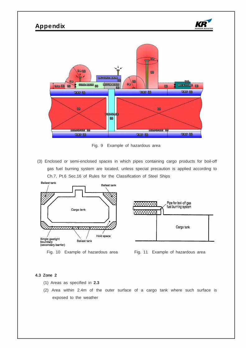
Appendix
Fig. 9 Example of hazardous area
(3) Enclosed or semi-enclosed spaces in which pipes containing cargo products for boil-off
gas fuel burning system are located, unless special precaution is applied according to
Ch.7, Pt.6 Sec.16 of Rules for the Classification of Steel Ships
Fig. 10 Example of hazardous area Fig. 11 Example of hazardous area
4.3 Zone 2
(1) Areas as specified in 2.3
(2) Area within 2.4m of the outer surface of a cargo tank where such surface is
exposed to the weather
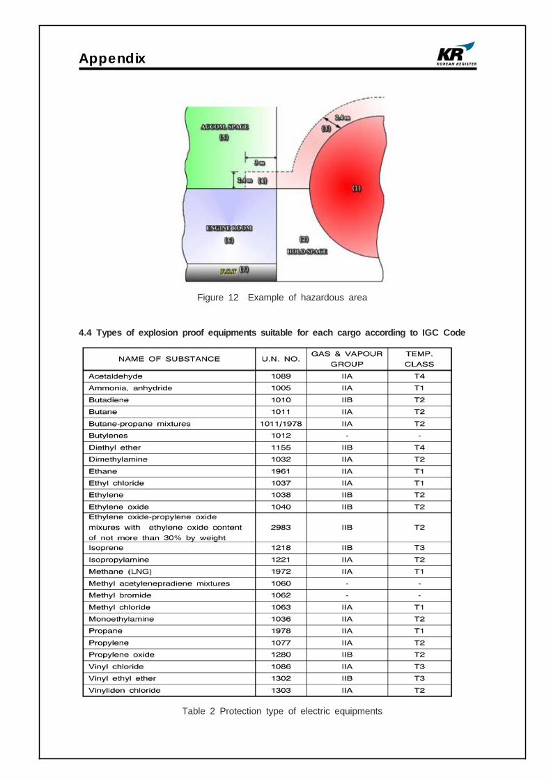
Appendix
Figure 12 Example of hazardous area
4.4 Types of explosion proof equipments suitable for each cargo according to IGC Code
Table 2 Protection type of electric equipments

Appendix
Requirements for Ballast Water Treatment in California

Korean Register of Shipping Page 1/7
KRKOREAN REGISTER OF SHIPPING
TECHNICALINFORMATION
23-7, Jang-Dong, Yusung-gu,
Yusung P. O. Box 29, Taejon,
The Republic of Korea
Phone
Fax
Date
: +82-42-869-9346
: +82-42-862-6098
: 1 September 2009
NO. 2009027/IMO Person in charge : Kim Kyong-Min
Subject : The notice for the application date for each ship and the
approval for Ballast Water Management Plan with regard to BWM
Convention
International Convention for the Control and Management of Ship's Ballast Water and
Sediments, 2004(hereinafter referred to "the convention) was adopted in February 2004
and has not been in effective yet. However, the convention will be retroactively applied
to the existing ships and new ships distinguished by the ship's delivery year of
2009(based on keel laying date) when it is entered into force.
The purpose of this Technical Information is to inform that First, the application date for
each vessel for Ballast water exchange standard(D-1) and Ballast water performance
standard, Second, the approval for Ballast water Management Plan(BWMP) which is dealt
with the procedure of Ballast water exchange and Ballast performance standard for the
ship, Third, the three methods which are described in the convention for Ballast water
exchange standard(D-1).
This Technical Information contains additional information to the previously KR issued
Technical Informations, 2007006/IMO(14 May 2007) and 2009007/IMO(04 March 2009)
which are issued with regard to the BWM Convention.
- Contents -
1. The application date for each vessel for Ballast water exchange
standard(D-1) and Ballast water performance standard(D-2) (Reg.B-3)
: The convention shall be applied to all ships including existing ships as shown in the table.

Korean Register of Shipping Page 2/7
Reg.B-3 Keel layingBW tank
capacity, ㎥2009 2010 2011 2012 2013 2014 2015 2016 2017
【Existing ships ; ships constructed before 2009】
Para.1.2 before 2009 less than
1,500 D1 or D2 D2
Para 1.1 before 2009between
1,500 and 5,000
D1 or D2 D2
Para 1.2 before 2009 greater than 5,000
D1 or D2 D2
【New ships ; ships constructed on or after 2009】
Para. 3 On or after 2009
less than 5,000
D2
Para. 4 on or after
2009, before 2012 5,000 or
more
D1 or D2 D2
Para. 5 on or after 2012 - D2
Based on ship's keel laying date, the D1 or D2 requirement shall be complied regardless
of the effective date of the convention.
"Constructed" referred in the convention and this technical Information means "ship's
Keel was laid" and "Anniversary date of delivery of the ship" means the day and the
month of each year based on the delivery date referred in IOPP(International Oil
Pollution Prevention) Cert. for the ship.
D1(Reg.D-1) means Ballast Water Exchange Standard and D2(Reg.D-2) means Ballast
Water Performance Standard.
[The application date of D1 and D2 for the existing ships and new ships]
1.1 For the existing ship(constructed before 2009), when the convention is
in effective
1) The existing ship shall comply with the D1(Ballast water exchange standard)
requirement not later than the first intermediate or renewal survey, whichever occurs
first, after the anniversary date of delivery of the ship in the year 2009 regardless of the
capacity of ballast water tanks.

Korean Register of Shipping Page 3/7
2) D2(ballast water performance standard) requirement shall be complied not later than
the following date depending on the capacity of ship's ballast water tank.
a) Ships carrying Ballast water less than 1,500㎥ or greater than 5,000㎥
⇒ Not later than the first intermediate or renewal survey, whichever occurs first, after
the anniversary date of delivery of the ship in the year 2016.
b) Ships carrying Ballast water capacity between 1,500㎥ and 5,000㎥
⇒ Not later than the first intermediate or renewal survey, whichever occurs first, after
the anniversary date of delivery of the ship in the year 2014.
1.2 For the new ship(constructed on or after 2009), when the convention is
in effective
a) Ships carrying ballast water less than 5,000㎥ which constructed on or after 2009
⇒ D2 requirement shall be applied at the time of construction of the ship
(According to Res.A.1005(25), a ship constructed in 2009(2009.01.01 〜 2009.12.31)
with a ballast capacity of less than 5,000 ㎥ may not be required to comply with regulation
D-2 until its second annual survey, but no later than 31 December 2011 subject to the
approval by the Administration as follows: ).
※ Notice
However, it should be noted that a ship constructed in 2009(2009.01.01 〜 2009.12.31)
with a Ballast Water Capacity of less than 5,000㎥ shall install BWMS which at least
meets the standard described in regulation D-2 as far as practicable except for the ship
owner's particular request.
b) Ships carrying ballast water more than 5,000㎥ which are constructed between 01
January 2009 and 31 December 2011
⇒ D1 requirement shall be applied as soon as the convention is in effective and D2
requirement shall be complied with not later than 31 December 2016.
c) Ships carrying ballast water capacity more than 5,000㎥ which are constructed on or
after 2012
⇒ D2 requirement shall be applied at the time of construction of the ship.

Korean Register of Shipping Page 4/7
2. The approval and the contents of Ballast Water Management
Plan(BWMP) (Reg. B-1)
: Each ship shall have the BWMP on board which was approved by This classification
society or Administrations in accordance with Guideline 4(Res.MEPC.127(53)).
※ If BWMP is approved only in accordance with the standard of Res.A868(20), it is
not an official Plan complying with the requirements of BWM Convention. Therefore,
BWM Certificate(or Statement of Compliance for BWM) can not be issued.
※ If "BWMP for BW exchange standards" only had been approved, "BWMP for Ballast
Water Management System" shall be approved additionally prior to installation of
BWMS.
2.1 The application date for approval of Ballast Water Management Plan
1) For existing ships(Constructed before 2009),
⇒ For the existing ships, when the convention is in effective, it will be retroactively
applied to the existing ships, therefore BWMP shall be approved not later than the first
intermediate or renewal survey, whichever occurs first, after the anniversary date of
delivery of the ship.
2) For new ships(Constructed on or after 2009),
a) Ships carrying ballast water capacity less than 5,000㎥ which are constructed on or
after 01 January 2009 or Ships carrying ballast water capacity more than 5,000㎥ which
are constructed on or after 01 January 2012
⇒ BWMP complying with D2 requirement shall be approved at the time of the
construction of the ships.
b) Ships carrying ballast water capacity more than 5,000㎥ which are constructed
between 1 January 2009 and 31 December 2011
⇒ BWMP shall be approved at the time of the construction of the ships because D1
requirement shall be applied as soon as the convention enters into force.

Korean Register of Shipping Page 5/7
2.2 The composition of BWMP (Reg. B-1)
.1 detail safety procedures for the ship and the crew associated with Ballast Water
Management as required by this Convention;
.2 provide a detailed description of the actions to be taken to implement the Ballast
Water Management requirements and supplemental Ballast Water Management
practices as set forth in this Convention;
.3 detail the procedures for the disposal of Sediments:
ⅰ) at sea; and
ⅱ) to shore;
.4 include the procedures for coordinating shipboard Ballast Water Management that
involves discharge to the sea with the authorities of the State into whose waters
such discharge will take place;
.5 designate the officer on board in charge of ensuring that the plan is properly
implemented;
.6 contain the reporting requirements for ships provided for under this Convention;
and
.7 be written in the working language of the ship. If the language used is not
English, French or Spanish, a translation into one of these languages shall be
include
3. The three methods described in the convention for Ballast water
exchange standard(D-1) (Refer to the convention Guideline 11 para.2 and
para.3.5)
: the three methods which are described in the convention are as follows. Among them
Flow-through method and Sequential method are used more often.
※ Attention:
If the existing ships use Flow-through method to comply with D1, additional works may
be necessary(such as installation of new air vents) to avoid over-pressure. In this case,
the prior consideration should be necessary before D1 requirement is applied to the ship
especially when the work only can carry out during Dry Docking for the ships. If
Sequential method is used, a particular attention should be given to the calculation of
ship's longitudinal strength.
3.1 Flow-through method
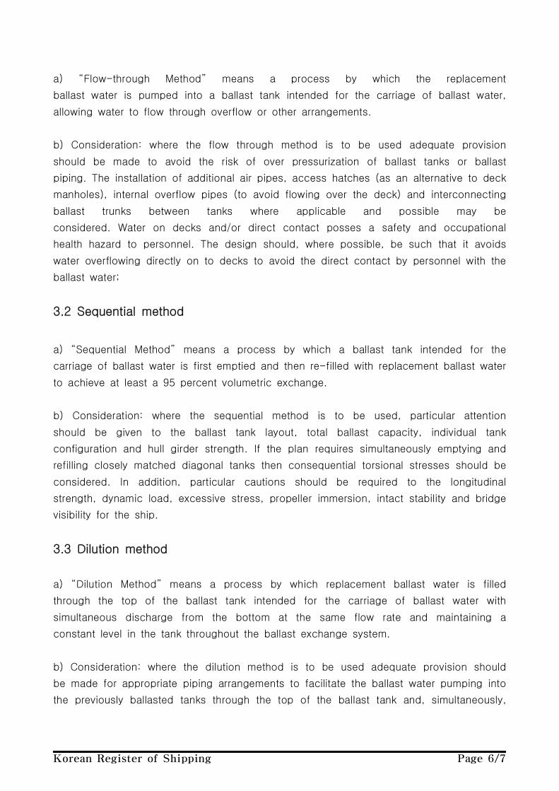
Korean Register of Shipping Page 6/7
a) “Flow-through Method” means a process by which the replacement
ballast water is pumped into a ballast tank intended for the carriage of ballast water,
allowing water to flow through overflow or other arrangements.
b) Consideration: where the flow through method is to be used adequate provision
should be made to avoid the risk of over pressurization of ballast tanks or ballast
piping. The installation of additional air pipes, access hatches (as an alternative to deck
manholes), internal overflow pipes (to avoid flowing over the deck) and interconnecting
ballast trunks between tanks where applicable and possible may be
considered. Water on decks and/or direct contact posses a safety and occupational
health hazard to personnel. The design should, where possible, be such that it avoids
water overflowing directly on to decks to avoid the direct contact by personnel with the
ballast water;
3.2 Sequential method
a) “Sequential Method” means a process by which a ballast tank intended for the
carriage of ballast water is first emptied and then re-filled with replacement ballast water
to achieve at least a 95 percent volumetric exchange.
b) Consideration: where the sequential method is to be used, particular attention
should be given to the ballast tank layout, total ballast capacity, individual tank
configuration and hull girder strength. If the plan requires simultaneously emptying and
refilling closely matched diagonal tanks then consequential torsional stresses should be
considered. In addition, particular cautions should be required to the longitudinal
strength, dynamic load, excessive stress, propeller immersion, intact stability and bridge
visibility for the ship.
3.3 Dilution method
a) “Dilution Method” means a process by which replacement ballast water is filled
through the top of the ballast tank intended for the carriage of ballast water with
simultaneous discharge from the bottom at the same flow rate and maintaining a
constant level in the tank throughout the ballast exchange system.
b) Consideration: where the dilution method is to be used adequate provision should
be made for appropriate piping arrangements to facilitate the ballast water pumping into
the previously ballasted tanks through the top of the ballast tank and, simultaneously,

Korean Register of Shipping Page 7/7
discharging the ballast water through the bottom of the tank at the same flow rate while
maintaining a constant ballast water level in the tank throughout the exchange operation.
Adequate provision should also be made to avoid the risk of over pressurization of
ballast tanks or ballast piping. The hydrodynamic performance of the ballast tank is
crucial to ensure full water exchange and sediment scouring. - the end -
Lim Sam-Taek
Executive Vice President
Statutory Survey Division
Korean Register of Shipping
Distributions : Ship owners, Shipyards and KR surveyors
Disclaimer :Although all possible efforts have been made to ensure correctness and completeness of the contents contained in this information service, the Korean Register of Shipping is not responsible for any errors or omissions made herein, nor held liable for any actions taken by any party as a result of information retrieved from this information service.

Appendix
Requirements for Ballast Water Treatment in New York

1
Subject : New York State Ballast Water Standards
This is to inform to ship owners/operators additional detailed information in accordance with
Ballast Water Standards included in Vessel General Permit of Environmental Protection
Agency.
As we previously informed through the KR technical information No. 2009003/ETC,
2010002/ETC, on 6 February 2009, all commercial vessels with discharges of pollutants
incidental to their normal operation, including but not limited to ballast water discharges,
into the US three mile territorial sea or inland waters became subject to the Environmental
Protection Agency's (EPA) Vessel General Permit (VGP) requirements and needs permit
coverage for all vessels with their length of 24 meters (79 feet) or longer, except fishing
vessels.
In this regard, the supplement 2.2.3(Discharges of Ballast Water) of Vessel General Permit
(VGP) provides the instruction to ship owners/operators in respect of caution points for
implementation of Ballast Water Standards as below.
1. Maintain a vessel-specific ballast water management plan.
- Master and crew must understand and follow plan.
- Plan must be available to EPA, upon request.
2. Clean ballast tanks regularly(no sediment discharge allowed).
3. Treat ballast water onshore, if available and economically practicable, and achievable or
use onboard ballast water treatment system approved by U.S Coast Guard.
On a basis of VGP, especially Ballast Water Management, New York State notifies that each
vessel covered under the VGP that operates in New York waters shall have a ballast water
treatment system that meets the standards prescribed by the states by not later than 1
January 2012.
Furthermore, new ships which are constructed on or after 1 January 2013 covered under
the VGP that operates in New York waters shall have a ballast water treatment system that
meets more stringent standards prescribed by the state.
New York three mile territorial sea or inland waters
Port Rule
All ship owners
No. 2010006/port 5th July 2010
Statutory Zone
Regulatory
Applicability
Port Rule Information

Port Rule Information
2
Organisms, microbes
New York StateIMO's standard
(Regulation D-2)Year 2012
(All)
Year 2013
(New Ship)Organisms 50µm or over <0.1 / m³ 0 / m³ <10 / m³Organisms 10µm-50µm <0.1 / ml <0.01 / ml <10 / ml
Toxicogenic vibrio cholerae
(0 1, 0 139)< 1 cfu / 100ml < 1 cfu / 100ml < 1 cfu / 100ml
Escherichia coli < 126 cfu / 100ml < 126 cfu / 100ml < 250 cfu / 100ml
Intestinal Enterococci < 33 cfu / 100ml < 33 cfu / 100ml < 100 cfu / 100ml
Bacteria N.A. < 1,000 / 100ml N.A.
Viruses N.A. < 10,000 / 100ml N.A.
The Requirements of New York State Ballast Water Standards are as following.
(cfu : colony forming unit)
There are the relevant information written in original document of VGP including overall
content of Ship Ballast Water Discharges and instruction of Marshall Islands and ICS
(International Chamber of Shipping) explaining approval procedure and extension request of
Ship Ballast Water Discharges in New York State.
The original document of VGP and Marine Guideline No.2-11-10 issued by the Marshall
Islands and MC(10)43 issued by ICS can be available through the following URL
respectively and attached files on this port information.
http://www.epa.gov/npdes/pubs/vessel_vgp_permit.pdf
Marine Guideline No.2-10-11
http://www.register-iri.com/forms/upload/MG-2-11-10.doc
MC(10)43
http://www.marisec.org/icsorange/icscirculars10/MC_10_43%20-%20NYState%20BW%20Requi
rements.pdf
Ship owners/operators are kindly requested to be noticed and pay attention to the above
information against checking for basis compliance with New York State Ballast Water
Standards in the VGP at the time of arriving at New York port.
General Manager
Convention & Legislation Service Team
Korean Register of Shipping
T +82-42-869-9340
F +82-42-862-6098
Disclaimer
Although all possible efforts have been made to ensure correctness and completeness of the contents contained in
this information service, the Korean Register of Shipping is not responsible for any errors or omissions made herein,
nor held liable for any actions taken by any party as a result of information retrieved from this information service.

Appendix
Means to Verify Ballast Water Treatment Systems for
Ships Entering Australian Ports

1
Subject : Verification tools of Ballast Water Management System for the
ships berthing in the Australia Port
This Port Rule Information is to inform to ship owners/operators the Guideline for the
Port State Control of Australia State, even though the Ballast Water Management
Convention is not effective, some ships already installed and operated onboard the
type-approved Ballast Water Management System, therefore, the Australia State have plans
to verify whether the ship complies with the specifications and instruction of manufacturer
or not, for the ships which installed onboard the Ballast Water Management System,
berthing in the Australia Port. Therefore, Korean-Register would like to provide the
detailed information as follows in accordance with verification tools for the Ballast Water
Management System and PSC inspection items on a basis of the document which was
submitted by Australia State(MEPC 61/INF.19).
- Contents -
1. HARMFUL AQUATIC ORGANISMS IN BALLAST WATER - MEPC 61/INF.19
1.1 Australia has applied ballast water management requirements in Australia waters since
2001 and is currently working towards the ratification of the Ballast Water
Management(BWM) Convention. Australia is progressing development of new legislation,
supporting tools and procedures to assist the effective implementation, compliance and
enforcement of the Convention.
1.2 In recognizing that some ships are being fitted or retrofitted with type-approved ballast
water management systems (BWMS), the development of tools to facilitate the
verification of the operation of these new systems is of particular interest. These tools
will assist compliance activity to verify that the system meets Australia's current
requirements and also for when the BWM Convention is in force.
1.3 These tools include a Treatment System Particular (TSP) document on individual
BWMS detailing its function and relevant aspects specific to the system (e.g., treatment
Australia inland waters
Port Rule (PSC)
All ship owners
No. 2010007/port 11th October 2010
Statutory Zone
Regulatory
Applicability
Port Rule Information

2
Verification Check Items
Sterilisation
The number of AOT units should correspond to the
BW pump capacity (1 unit[AOT] = 250 m³/h)
Request crew to open the AOT unit control box to
ascertain operational activity with no warning lights
Control Panel,
Storage in BW tanks
and discharge,
Cleaning in Place Unit
Request maintenance log to examine records
of routine crew checks (note every 3 months)
Cleaning solution should be pH 3 or lower
Note CIP fluid levels which should be replaced/refilled
whenever pH is > 3, or level is low
Maintenance
How often is filter inspected or replaced?
What is minimum number of UV lamps that can be
faulty in a reactor? (all lamps need to be operational)
How often are UV lamps checked?
(lifetime expectancy is 1500 hours of operation)
What is pH of the cleaning solution in the CIP unit,
and how often is it checked?
Data
Compare the recent ballast activity (total volume
and pump capacity) with the Ballast Water Record
Book and the Ballast Water Management Plan
Identify if any system alarms have been triggered (Note that the
system will be shut down automatically when a problem occurs)
on uptake and discharge, flow rates or retention periods, etc.). These TSPs are being
developed in consultation with BWMS manufacturers, local governments and industry.
1.4 The TSP and associated verification procedure is designed to provide inspection officers
with information to verify that the particular system has been operated in accordance
with the manufacturer's instructions and the ship's ballast water management plan. The
TSP and verification procedure will complement port state control guideline under the
Convention. An example of a TSP and verification checklist is provided at the annex.
Also, Australia invites Member States to consider the benefit of using these tools and
procedures to assist in the inspection and verification of the operation of BWMS, this is
already mentioned through the Marine Environment Protection Committee 61st session
Agenda item 2.
1.5 At the time of MEPC 61st session, on the Treatment System Particulars (TSP)
attached on the document of MEPC 61/INF.19 submitted by Australia State, verification
check items of BWMS which were made for PSC inspection officers are as below.

Port Rule Information
3
Ascertain that no components of
the system have been bypassed
Ascertain that the system has not shutdown during
ballasting and/or deballasting.(If it has, then it is
important to ascertain that any problems have been fixed)
* If all the verification checks are positive then the ballast water management system
should be considered to be operating effectively.
In addition, attached files are Treatment System Particular (TSP) including functional details
of Ballast Water Management System designed by a specific manufacturer and verification
check items. Accordingly, ship owners/operators are kindly requested to be noticed and pay
attention to the above information against checking for compliance with Treatment System
Particular (TSP) and verification checklists in accordance with PSC inspection of BWMS.
-The end-
General Manager
Convention & Legislation Service Team
Korean Register of Shipping
T +82-42-869-9340
F +82-42-862-6098
Disclaimer
Although all possible efforts have been made to ensure correctness and completeness of the contents contained in
this information service, the Korean Register of Shipping is not responsible for any errors or omissions made herein,
nor held liable for any actions taken by any party as a result of information retrieved from this information service.
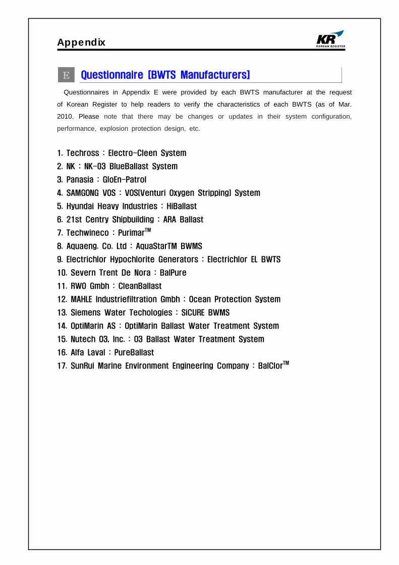
Appendix
Questionnaire [BWTS Manufacturers]
Questionnaires in Appendix E were provided by each BWTS manufacturer at the request
of Korean Register to help readers to verify the characteristics of each BWTS (as of Mar.
2010. Please note that there may be changes or updates in their system configuration,
performance, explosion protection design, etc.
1. Techross : Electro-Cleen System
2. NK : NK-03 BlueBallast System
3. Panasia : GloEn-Patrol
4. SAMGONG VOS : VOS(Venturi Oxygen Stripping) System
5. Hyundai Heavy Industries : HiBallast
6. 21st Centry Shipbuilding : ARA Ballast
7. Techwineco : PurimarTM
8. Aquaeng. Co. Ltd : AquaStarTM BWMS
9. Electrichlor Hypochlorite Generators : Electrichlor EL BWTS
10. Severn Trent De Nora : BalPure
11. RWO Gmbh : CleanBallast
12. MAHLE Industriefiltration Gmbh : Ocean Protection System
13. Siemens Water Techologies : SiCURE BWMS
14. OptiMarin AS : OptiMarin Ballast Water Treatment System
15. Nutech O3, Inc. : O3 Ballast Water Treatment System
16. Alfa Laval : PureBallast
17. SunRui Marine Environment Engineering Company : BalClorTM
Machinery Team of KR
Korean Register of Shipping, with the objective of GLOBAL TOP+, will always do our best
to provide the costumers with quicker and better quality services.
As the implementation of the Ballast Water Management Convention is imminent,
consideration is being given to the ship's design changes in relation to the installation of
Ballast Water Treatment System (hereinafter referred to as 'BWTS'), which is now put in
place on board some new ships.
The Machinery Team of this Society is planning to publish a Guidance for Installation of the
BWTS.
The KR's BWTS Guidance is intended to assist shipyards and ship owners in selecting
appropriate BWTS by describing the physical and mechanical properties of the BWTS,
technical aspects to be considered at the time of installation, and specific considerations
per each ship type.
In order for us to be able to complete the BWTS Guidance, we would highly appreciate it if
you could fill the questionnaire in as much as possible, and submit to us the completed
questionnaire by 30 April 2011 at the latest.
Your responses to the questionnaire are required for guidance purposes only and will not
be disclosed partly or wholly if specifically requested by the respondents.
Oh Joo-won / General Manager of Machinery Team
Korean Register of Shipping Please return completed questionnaire to ; Fax : +82 42-862-6016 E-mail : [email protected] (Contact : Jang Jae-shik, +82-42-869-9456)
Questionnaire about
Ballast Water Treatment System

Machinery Team of KR
Thank you for participating in the BWTS Guidance questionnaire. If you have any questions
about how to complete it, please contact Jang Jae-shik, KR Machinery Team by phone: +82-42-
869-9456 or E-mail: [email protected]
1. Please describe about your company
Company name Techcross Person in Charge Mr. J. W. Lee
Telephone No. 02 3775 7777
Fax. No. 02 3775 7788
E-mail [email protected]
2. Please describe briefly about the Ballast Water Treatment System(hereinafter referred to as
'BWTS') manufactured by your company.
1) Product Name :
- ECS (Electro-Cleen TM System)
2) Treatment Type (e.g. electrolysis, UV, ozone, ozone+electrolysis, etc.) :
- Electrolysis Disinfection
3) In which process does the ballast water treatment occur ?
Treatment process Put a mark(○) in the relevant row
Ballasting O
De-ballasting
Ballasting and De-ballasting
In the ballast tank
Others
(describe in detail)
3. Please list strengths of your BWTS.

Machinery Team of KR
4. Please describe what needs to be specially considered when your BWTS is installed on
board ships.
1) Consider the maintenance space for ECS components
2) Consider the electric consumption of ECS components
3) Consider the equal flow rate when the ECU(Electro-Chamber Unit)s are operated in
parallel
5. Please fill in all applicable columns of the following table about the power consumption and
the required space.
1) ECU300 Model
2) ECU600 Model

Machinery Team of KR
6. In case of ships carrying dangerous cargoes (such as Oil / Chemical Tanker, Gas Carrier), please indicate the spaces where each part and
equipment of your BWTS are installed.[Put (○) or description in all relevant rows and columns]
(e.g. ECU, UV chamber)
Installed Spaces Explosion
Proof TypeE/R(Cargo/Ballast)
Pump Room
On-deck
(Hazardous Area)
On-deck
(Non-Hazardous Area)
Other Space
[If applicable, fill out the belows]
Ballast Water
Treatment
Equipment
ECU
(Electro-Chamber Unit) O O O Y
ANU
(Auto Neut. Unit) O O N
PRE
(Power Ref. Equip) O O N
Control and
Monitoring
Equipment
TRO Sensor Unit O O N
Gas Sensor Unit O O N
Flow Meter Unit O O N
Conductivity Sensor Unit O O O N
Power Distributor Equip. O O O Y
Power Control Unit O O N

Machinery Team of KR
7. In case where the BWTS is installed on board Oil/Chemical Tankers and if it is equipped with
monitoring devices which take samples from ballast pipe lines, please answer the following questions.
No. Question Answer
1 What sampling type of monitoring equipment is used?
□ N/A ■ TRO Sensor Unit ■ Gas Sensor Unit □ Others :
2 Is the monitoring equipment an explosion-proof type? □ Yes ■ No
3 Where is the monitoring equipment installed?
■ E/R □ (Ballast or Cargo)Pump Room ■ Others :
4
If the monitoring equipment of sampling type is installed in safety areas (e.g. E/R, Dedicated space) outside the cargo dangerous area, what kind of safety measures is taken against the risk of toxic or flammable gas?
■ Mechanical Ventilation ■ Gas Detection & Alarm □ Self-closing Gas-tight Door □ Others :
7-1. In the above case and where components are directly fitted in ballast pipe line,
please answer the following questions.
No. Question Answer Explosion Proof Type
1 What components are directly fitted in ballast pipe line?
□ N/A ■ TRO Sensor Unit □ Yes ■ No ■ Gas Sensor Unit □ Yes ■ No ■ Flow Meter Unit ■ Yes □ No □ Level Sensor Unit □ Yes □ No □ Temp. Sensor Unit □ Yes □ No ■ Pressure Sensor Unit ■ Yes □ No □ Other 1 :
□ Yes □ No
□ Other 2 :
□ Yes □ No
2
If the components are not of an explosion-proof type, what kind of safety measures is taken against the expected hazard?
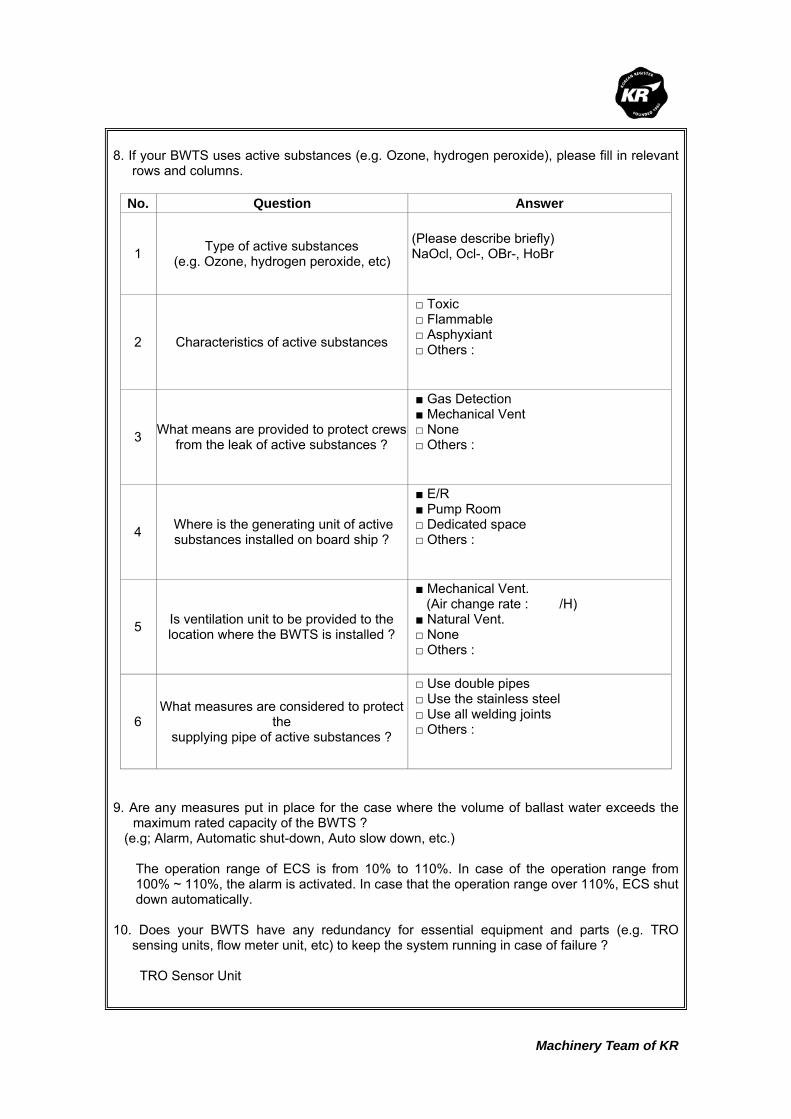
Machinery Team of KR
8. If your BWTS uses active substances (e.g. Ozone, hydrogen peroxide), please fill in relevant
rows and columns.
No. Question Answer
1 Type of active substances (e.g. Ozone, hydrogen peroxide, etc)
(Please describe briefly) NaOcl, Ocl-, OBr-, HoBr
2 Characteristics of active substances
□ Toxic □ Flammable □ Asphyxiant □ Others :
3 What means are provided to protect crews from the leak of active substances ?
■ Gas Detection ■ Mechanical Vent □ None □ Others :
4 Where is the generating unit of active substances installed on board ship ?
■ E/R ■ Pump Room □ Dedicated space □ Others :
5 Is ventilation unit to be provided to the location where the BWTS is installed ?
■ Mechanical Vent. (Air change rate : /H) ■ Natural Vent. □ None □ Others :
6 What measures are considered to protect
the supplying pipe of active substances ?
□ Use double pipes □ Use the stainless steel □ Use all welding joints □ Others :
9. Are any measures put in place for the case where the volume of ballast water exceeds the
maximum rated capacity of the BWTS ? (e.g; Alarm, Automatic shut-down, Auto slow down, etc.)
The operation range of ECS is from 10% to 110%. In case of the operation range from 100% ~ 110%, the alarm is activated. In case that the operation range over 110%, ECS shut down automatically.
10. Does your BWTS have any redundancy for essential equipment and parts (e.g. TRO
sensing units, flow meter unit, etc) to keep the system running in case of failure ? TRO Sensor Unit

Machinery Team of KR
11. Where are the spaces that you recommend to install sampling equipment according to BWM Convention/Guideline G2 ? (e.g; Ballast Water Discharge Line, etc.) The sampling is carried out with a manhole in ECS. 12. Regarding the bi-products that are generated from the ballast water treatment process,
please fill in all relevant rows. No. Question Answer
1 Are dangerous gases generated as by-products after ballast water treatment process?
■ Yes □ No
2 What type of dangerous gases is generated? (e.g; Hydrogen, chlorine, etc.)
3 What are properties of the by- product?
□ Toxic ■ Flammable □ Asphyxiant □ Others :
4
What is the generation rate of dangerous gases per each type of BWTS ? (e.g. 1m3/hr, etc) Please use a separate sheet if needed.
ECS300(1set) : H2 0.7m3/Hr, 63g
5 Is the gas detection unit an explosion-proof type? □ Yes ■ No
6
Where are the residue gases ventilated to aftergas detection? (e.g. installation location of the gas detection unit,or safety area on the exposed weather deck)
- Monitor H2 continuously - Vent H2 to poop deck by
mechanical vent. system

Machinery Team of KR
Korean Register of Shipping, with the objective of GLOBAL TOP+, will always do our best
to provide the costumers with quicker and better quality services.
As the implementation of the Ballast Water Management Convention is imminent,
consideration is being given to the ship's design changes in relation to the installation of
Ballast Water Treatment System (hereinafter referred to as 'BWTS'), which is now put in
place on board some new ships.
The Machinery Team of this Society is planning to publish a Guidance for Installation of the
BWTS.
The KR's BWTS Guidance is intended to assist shipyards and ship owners in selecting
appropriate BWTS by describing the physical and mechanical properties of the BWTS,
technical aspects to be considered at the time of installation, and specific considerations
per each ship type.
In order for us to be able to complete the BWTS Guidance, we would highly appreciate it if
you could fill the questionnaire in as much as possible, and submit to us the completed
questionnaire by 30 April 2011 at the latest.
Your responses to the questionnaire are required for guidance purposes only and will not
be disclosed partly or wholly if specifically requested by the respondents.
Oh Joo-won / General Manager of Machinery Team
Korean Register of Shipping Please return completed questionnaire to ; Fax : +82 42-862-6016 E-mail : [email protected] (Contact : Jang Jae-shik, +82-42-869-9456)
Questionnaire about
Ballast Water Treatment System

Machinery Team of KR
Thank you for participating in the BWTS Guidance questionnaire. If you have any questions
about how to complete it, please contact Jang Jae-shik, KR Machinery Team by phone: +82-42-
869-9456 or E-mail: [email protected]
1. Please describe about your company
Company name NK Person in Charge Mr. S. J. Park
Telephone No. 051-200-0810
Fax. No. 051-207-2208
E-mail [email protected]
2. Please describe briefly about the Ballast Water Treatment System(hereinafter referred to as
'BWTS') manufactured by your company.
1) Product Name :
- NK-O3 BlueBallast System
2) Treatment Type (e.g. electrolysis, UV, ozone, ozone+electrolysis, etc.) :
- Onzone : Side Stream Ozone Injection
3) In which process does the ballast water treatment occur ?
Treatment process Put a mark(○) in the relevant row
Ballasting O
De-ballasting
Ballasting and De-ballasting
In the ballast tank
Others
(describe in detail)
3. Please list strengths of your BWTS.
1) Applicable all kinds of vessels
2) To install on new/existing vessels without correction of design
3) No head loss
4) Low operating cost (0.8 cent/m3)

Machinery Team of KR
4. Please describe what needs to be specially considered when your BWTS is installed on
board ships.
1) To design an inserting line in ballast discharge lines
2) To consider the installation space
3) To arrange an injection piece at the side of a pump discharge in case that ballast pumps
are installed in dangerous area or underwater
5. Please fill in all applicable columns of the following table about the power consumption and
the required space.
용량(m3/h) 소비전력(kW) 설치공간(L x B x H)m
250 36.2 4.2
300 36.5 4.2
600 60.4 6.6
800 68.4 9.1
1000 86.9 8.3
1500 123.2 10.6
2000 148.4 14.5
3000 243.5 17.0
4000 317.6 20.3
5000 385.8 23.9
6000 438.3 25.3
기타 : 8000 613.8 36.8
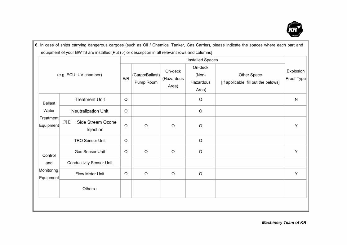
Machinery Team of KR
6. In case of ships carrying dangerous cargoes (such as Oil / Chemical Tanker, Gas Carrier), please indicate the spaces where each part and
equipment of your BWTS are installed.[Put (○) or description in all relevant rows and columns]
(e.g. ECU, UV chamber)
Installed Spaces
Explosion
Proof Type E/R(Cargo/Ballast)
Pump Room
On-deck
(Hazardous
Area)
On-deck
(Non-
Hazardous
Area)
Other Space
[If applicable, fill out the belows]
Ballast
Water
Treatment
Equipment
Treatment Unit O O N
Neutralization Unit O O
기타 : Side Stream Ozone Injection
O O O O Y
Control
and
Monitoring
Equipment
TRO Sensor Unit O O
Gas Sensor Unit O O O O Y
Conductivity Sensor Unit
Flow Meter Unit O O O O Y
Others :
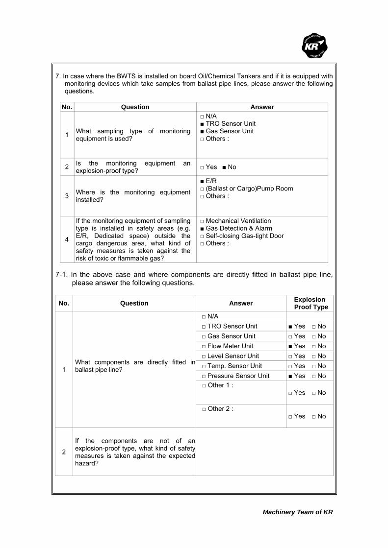
Machinery Team of KR
7. In case where the BWTS is installed on board Oil/Chemical Tankers and if it is equipped with
monitoring devices which take samples from ballast pipe lines, please answer the following questions.
No. Question Answer
1 What sampling type of monitoring equipment is used?
□ N/A ■ TRO Sensor Unit ■ Gas Sensor Unit □ Others :
2 Is the monitoring equipment an explosion-proof type? □ Yes ■ No
3 Where is the monitoring equipment installed?
■ E/R □ (Ballast or Cargo)Pump Room □ Others :
4
If the monitoring equipment of sampling type is installed in safety areas (e.g. E/R, Dedicated space) outside the cargo dangerous area, what kind of safety measures is taken against the risk of toxic or flammable gas?
□ Mechanical Ventilation ■ Gas Detection & Alarm □ Self-closing Gas-tight Door □ Others :
7-1. In the above case and where components are directly fitted in ballast pipe line,
please answer the following questions.
No. Question Answer Explosion Proof Type
1 What components are directly fitted in ballast pipe line?
□ N/A □ TRO Sensor Unit ■ Yes □ No □ Gas Sensor Unit □ Yes □ No □ Flow Meter Unit ■ Yes □ No □ Level Sensor Unit □ Yes □ No □ Temp. Sensor Unit □ Yes □ No □ Pressure Sensor Unit ■ Yes □ No □ Other 1 :
□ Yes □ No
□ Other 2 :
□ Yes □ No
2
If the components are not of an explosion-proof type, what kind of safety measures is taken against the expected hazard?

Machinery Team of KR
8. If your BWTS uses active substances (e.g. Ozone, hydrogen peroxide), please fill in relevant
rows and columns.
No. Question Answer
1 Type of active substances (e.g. Ozone, hydrogen peroxide, etc)
(Please describe briefly)
2 Characteristics of active substances
■ Toxic □ Flammable □ Asphyxiant □ Others :
3 What means are provided to protect crews from the leak of active substances ?
■ Gas Detection □ Mechanical Vent □ None □ Others :
4 Where is the generating unit of active substances installed on board ship ?
■ E/R □ Pump Room □ Dedicated space □ Others :
5 Is ventilation unit to be provided to the location where the BWTS is installed ?
□ Mechanical Vent. (Air change rate : /H) ■ Natural Vent. □ None □ Others :
6 What measures are considered to protect
the supplying pipe of active substances ?
□ Use double pipes ■ Use the stainless steel □ Use all welding joints □ Others :
9. Are any measures put in place for the case where the volume of ballast water exceeds the
maximum rated capacity of the BWTS ? (e.g; Alarm, Automatic shut-down, Auto slow down, etc.) To activate alarm in excess of its capacity or control flow rate 10. Does your BWTS have any redundancy for essential equipment and parts (e.g. TRO
sensing units, flow meter unit, etc) to keep the system running in case of failure ? TRO Sensor

Machinery Team of KR
11. Where are the spaces that you recommend to install sampling equipment according to BWM
Convention/Guideline G2 ? (e.g; Ballast Water Discharge Line, etc.) Ballast discharge line 12. Regarding the bi-products that are generated from the ballast water treatment process,
please fill in all relevant rows. No. Question Answer
1 Are dangerous gases generated as by-products after ballast water treatment process?
□ Yes ■ No
2 What type of dangerous gases is generated? (e.g; Hydrogen, chlorine, etc.)
3 What are properties of the by- product?
□ Toxic □ Flammable □ Asphyxiant □ Others :
4
What is the generation rate of dangerous gasesper each type of BWTS ? (e.g. 1m3/hr, etc) Please use a separate sheet if needed.
5 Is the gas detection unit an explosion-proof type? ■ Yes □ No
6
Where are the residue gases ventilated to aftergas detection? (e.g. installation location of the gas detection unit,or safety area on the exposed weather deck)
Natural vent. space

Machinery Team of KR
Korean Register of Shipping, with the objective of GLOBAL TOP+, will always do our best
to provide the costumers with quicker and better quality services.
As the implementation of the Ballast Water Management Convention is imminent,
consideration is being given to the ship's design changes in relation to the installation of
Ballast Water Treatment System (hereinafter referred to as 'BWTS'), which is now put in
place on board some new ships.
The Machinery Team of this Society is planning to publish a Guidance for Installation of the
BWTS.
The KR's BWTS Guidance is intended to assist shipyards and ship owners in selecting
appropriate BWTS by describing the physical and mechanical properties of the BWTS,
technical aspects to be considered at the time of installation, and specific considerations
per each ship type.
In order for us to be able to complete the BWTS Guidance, we would highly appreciate it if
you could fill the questionnaire in as much as possible, and submit to us the completed
questionnaire by 31 March 2010 at the latest.
Your responses to the questionnaire are required for guidance purposes only and will not
be disclosed partly or wholly if specifically requested by the respondents.
Oh Joo-won / General Manager of Machinery Team
Korean Register of Shipping Please return completed questionnaire to ; Fax : +82 42-862-6016 Email : [email protected] (Contact : Jee Jae-hoon, +82-42-869-9474)
Questionnaire about
Ballast Water Treatment System

Machinery Team of KR
Thank you for participating in the BWTS Guidance questionnaire. If you have any questions
about how to complete it, please contact Jee Jae-hoon, KR Machinery Team by phone: +82-42-
869-9474 or email: [email protected]
1. Please describe about your company
Company name PANASIA CO., LTD. Person in Charge Hyun-O, Kim
Telephone No. 051-970-1537
Fax. No. 051-831-1399
E-mail [email protected]
2. Please describe briefly about the Ballast Water Treatment System(hereinafter referred to as
'BWTS') manufactured by your company.
1) Product Name : GloEn-PatrolTM
2) Treatment Type (e.g. electrolysis, UV, ozone, ozone+electrolysis, etc.) :
Filter + UV Disinfection
The 1st stage is a filter that was specially designed for ballast water applications. It significantly
reduces the sediment load of the ballast water and also removes some of the microorganisms.
The UV unit employs high-intensity, medium-pressure ultra violet (MPUV) lamps to destroy living
microorganisms present in the liquid being treated.
3) In which process does the ballast water treatment occur ?
Treatment process Put a mark(○) in the relevant row
Ballasting
De-ballasting
Ballasting and De-ballasting ○
In the ballast tank
Others
(describe in detail)
3. Please list strengths of your BWTS.
1) Automatic cleaning, Easy maintenance.
2) No biocide chemicals are required.
3) No toxic by-products are formed. No corrosion problems in ballast tanks.
4) The process requires little maintenance and easy handling.
5) Optimized design for each sizes and type of ship.

Machinery Team of KR
4. Please describe what needs to be specially considered when your BWTS is installed on
board ships.
1) Installation of Filter back-flushing pump (It depend on ship’s design) : Option
2)
3)
5. Please fill in all applicable columns of the following table about the power consumption and
the required space.
Treatment Capacity
(m3/h) Power Consumption (kW) Required Space (L x B x H)m
100
200
300
400
500
600
700
800
900
1000
1500
2000
2500
3000
3500
4000
4500
5000
6000
7000
Others :
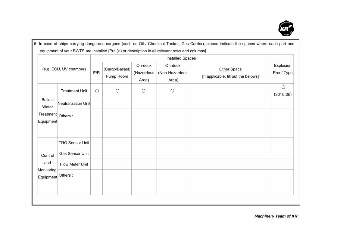
Machinery Team of KR
6. In case of ships carrying dangerous cargoes (such as Oil / Chemical Tanker, Gas Carrier), please indicate the spaces where each part and
equipment of your BWTS are installed.[Put (○) or description in all relevant rows and columns]
(e.g. ECU, UV chamber)
Installed Spaces
Explosion
Proof TypeE/R(Cargo/Ballast)
Pump Room
On-deck
(Hazardous
Area)
On-deck
(Non-Hazardous
Area)
Other Space
[If applicable, fill out the belows]
Ballast
Water
Treatment
Equipment
Treatment Unit ○ ○ ○ ○ ○
(2010.06)
Neutralization Unit
Others :
Control
and
Monitoring
Equipment
TRO Sensor Unit
Gas Sensor Unit
Flow Meter Unit
Others :

Machinery Team of KR
7. In case where the BWTS is installed on board Oil/Chemical Tankers and if it is equipped with
monitoring devices which take samples from ballast pipe lines, please answer the following questions. : There are no devices which take samples from ballast pipe lines in our BWMS.
No. Question Answer
1 What sampling type of monitoring equipment is used?
□ N/A □ TRO Sensor Unit □ Gas Sensor Unit □ Others :
2 Is the monitoring equipment an explosion-proof type? □ Yes □ No
3 Where is the monitoring equipment installed?
□ E/R □ (Ballast or Cargo)Pump Room □ Others :
4
If the monitoring equipment of sampling type is installed in safety areas (e.g. E/R, Dedicated space) outside the cargo dangerous area, what kind of safety measures is taken against the risk of toxic or flammable gas?
□ Mechanical Ventilation □ Gas Detection & Alarm □ Self-closing Gas-tight Door □ Others :
7-1. In the above case and where components are directly fitted in ballast pipe line,
please answer the following questions.
No. Question Answer Explosion Proof Type
1 What components are directly fitted in ballast pipe line?
□ N/A □ TRO Sensor Unit □ Yes □ No □ Gas Sensor Unit □ Yes □ No ☑ Flow Meter Unit ☑ Yes □ No
□ Level Sensor Unit □ Yes □ No □ Temp. Sensor Unit □ Yes □ No ☑ Pressure Sensor Unit ☑ Yes □ No □ Other 1 :
□ Yes □ No
□ Other 2 :
□ Yes □ No
2
If the components are not of an explosion-proof type, what kind of safety measures is taken against the expected hazard?
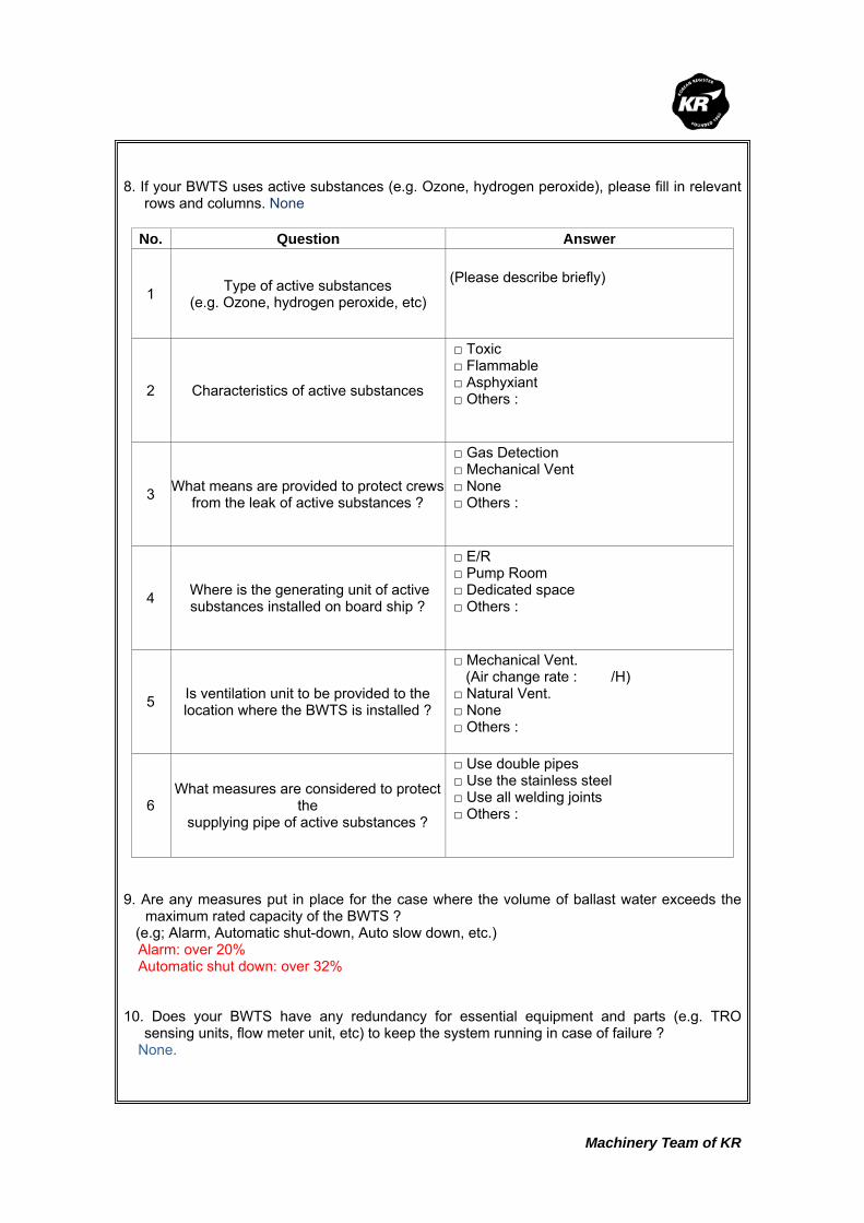
Machinery Team of KR
8. If your BWTS uses active substances (e.g. Ozone, hydrogen peroxide), please fill in relevant
rows and columns. None
No. Question Answer
1 Type of active substances (e.g. Ozone, hydrogen peroxide, etc)
(Please describe briefly)
2 Characteristics of active substances
□ Toxic □ Flammable □ Asphyxiant □ Others :
3 What means are provided to protect crews from the leak of active substances ?
□ Gas Detection □ Mechanical Vent □ None □ Others :
4 Where is the generating unit of active substances installed on board ship ?
□ E/R □ Pump Room □ Dedicated space □ Others :
5 Is ventilation unit to be provided to the location where the BWTS is installed ?
□ Mechanical Vent. (Air change rate : /H) □ Natural Vent. □ None □ Others :
6 What measures are considered to protect
the supplying pipe of active substances ?
□ Use double pipes □ Use the stainless steel □ Use all welding joints □ Others :
9. Are any measures put in place for the case where the volume of ballast water exceeds the
maximum rated capacity of the BWTS ? (e.g; Alarm, Automatic shut-down, Auto slow down, etc.) Alarm: over 20% Automatic shut down: over 32% 10. Does your BWTS have any redundancy for essential equipment and parts (e.g. TRO
sensing units, flow meter unit, etc) to keep the system running in case of failure ? None.

Machinery Team of KR
11. Where are the spaces that you recommend to install sampling equipment according to BWM
Convention/Guideline G2 ? (e.g; Ballast Water Discharge Line, etc.) Ballast water discharge line. (after BWMS) 12. Regarding the bi-products that are generated from the ballast water treatment process,
please fill in all relevant rows. None No. Question Answer
1 Are dangerous gases generated as by-products after ballast water treatment process?
□ Yes □ No
2 What type of dangerous gases is generated? (e.g; Hydrogen, chlorine, etc.)
3 What are properties of the by- product?
□ Toxic □ Flammable □ Asphyxiant □ Others :
4
What is the generation rate of dangerous gases per each type of BWTS ? (e.g. 1m3/hr, etc) Please use a separate sheet if needed.
5 Is the gas detection unit an explosion-proof type? □ Yes □ No
6
Where are the residue gases ventilated to aftergas detection? (e.g. installation location of the gas detection unit,or safety area on the exposed weather deck)

Machinery Team of KR
Korean Register of Shipping, with the objective of GLOBAL TOP+, will always do our best
to provide the costumers with quicker and better quality services.
As the implementation of the Ballast Water Management Convention is imminent,
consideration is being given to the ship's design changes in relation to the installation of
Ballast Water Treatment System (hereinafter referred to as 'BWTS'), which is now put in
place on board some new ships.
The Machinery Team of this Society is planning to publish a Guidance for Installation of the
BWTS.
The KR's BWTS Guidance is intended to assist shipyards and ship owners in selecting
appropriate BWTS by describing the physical and mechanical properties of the BWTS,
technical aspects to be considered at the time of installation, and specific considerations
per each ship type.
In order for us to be able to complete the BWTS Guidance, we would highly appreciate it if
you could fill the questionnaire in as much as possible, and submit to us the completed
questionnaire by 30 April 2011 at the latest.
Your responses to the questionnaire are required for guidance purposes only and will not
be disclosed partly or wholly if specifically requested by the respondents.
Oh Joo-won / General Manager of Machinery Team
Korean Register of Shipping Please return completed questionnaire to ; Fax : +82 42-862-6016 E-mail : [email protected] (Contact : Jang Jae-shik, +82-42-869-9456)
Questionnaire about
Ballast Water Treatment System

Machinery Team of KR
Thank you for participating in the BWTS Guidance questionnaire. If you have any questions
about how to complete it, please contact Jang Jae-shik, KR Machinery Team by phone: +82-42-
869-9456 or E-mail: [email protected]
1. Please describe about your company
Company name SAMGONG VOS CO., LTD
Person in Charge Cho, Young Mook
Telephone No. 051-200-3080
Fax. No. 051-200-3046
E-mail [email protected]
2. Please describe briefly about the Ballast Water Treatment System(hereinafter referred to as
'BWTS') manufactured by your company.
1) Product Name : VOS (Venturi Oxygen Stripping) System
2) Treatment Type (e.g. electrolysis, UV, ozone, ozone+electrolysis, etc.) :
De-oxygenation
This system injects Inert Gas which is generated by an IGG (Inert Gas Generator) into
ballast water through a Ventury Injector to maintain the rate of dissolved oxygen in the
ballast water to a certain level (7ppm 1ppm) to sterilize micro-organisms in the ballast
water and consequently meet the requirements of IMO D-2.
3) In which process does the ballast water treatment occur ?
Treatment process Put a mark(○) in the relevant row
Ballasting O
De-ballasting
Ballasting and De-ballasting
In the ballast tank
Others
(describe in detail)
3. Please list strengths of your BWTS.
1) User friendly equipment (Similar to inerting equipment for cargo tanks)
2) Effective for ballast tank corrosion protection
3) Can be used in hazardous areas
4) Does not make use of dangerous active substances
5) Easy to assess system performance (Simply by measuring the rate of dissolved oxygen
(below 1ppm))

Machinery Team of KR
4. Please describe what needs to be specially considered when your BWTS is installed on
board ships.
1) Riser loop piping coupled to a ballast pump need to be installed on main deck level.
2) The system requires secondary deck piping for an inert gas system inside the ballast
tank.
3) Since the I.G.G. burns DMA, relevant fire safety protection and ventilation (E/R only)
should be considered.
5. Please fill in all applicable columns of the following table about the power consumption and
the required space.
Treatment Capacity
(m3/h) Power Consumption (kW) Required Space (L x B x H)m
100 17.3 2.5x0.9x1.9 (4.8x3.4x2.4)
200 17.3 2.5x0.9x1.9 (4.8x3.4x2.4)
300 17.3 2.5x0.9x1.9 (4.8x3.4x2.4)
400 24.3 2.5x0.9x1.9 (4.8x3.4x2.4)
500 24.3 2.5x0.9x1.9 (4.8x3.4x2.4)
600 24.3 2.7x1.5x2.2 (5.0x4.0x2.7)
700 24.3 2.7x1.5x2.2 (5.0x4.0x2.7)
800 24.3 2.7x1.5x2.2 (5.0x4.0x2.7)
900 24.3 2.7x1.5x2.2 (5.0x4.0x2.7)
1000 40.3 2.7x1.5x2.2 (5.0x4.0x2.7)
1500 62.3 3.2x1.8x2.6 (5.5x4.3x3.1)
2000 62.3 3.2x1.8x2.6 (5.5x4.3x3.1)
2500 92.3 3.8x2.1x3.0 (6.1x4.6x3.5)
3000 92.3 3.8x2.1x3.0 (6.1x4.6x3.5)
3500 112.3 4.0x2.2x3.4 (6.3x4.7x3.9)
4000 152.3 4.0x2.2x3.4 (6.3x4.7x3.9)
4500 152.3 5.0x2.6x3.6 (7.3x5.1x4.1)
5000 152.3 5.0x2.6x3.6 (7.3x5.1x4.1)
6000 182.3 5.0x2.6x3.6 (7.3x5.1x4.1)
7000 224.5 3500 Model x 2 sets
Others :
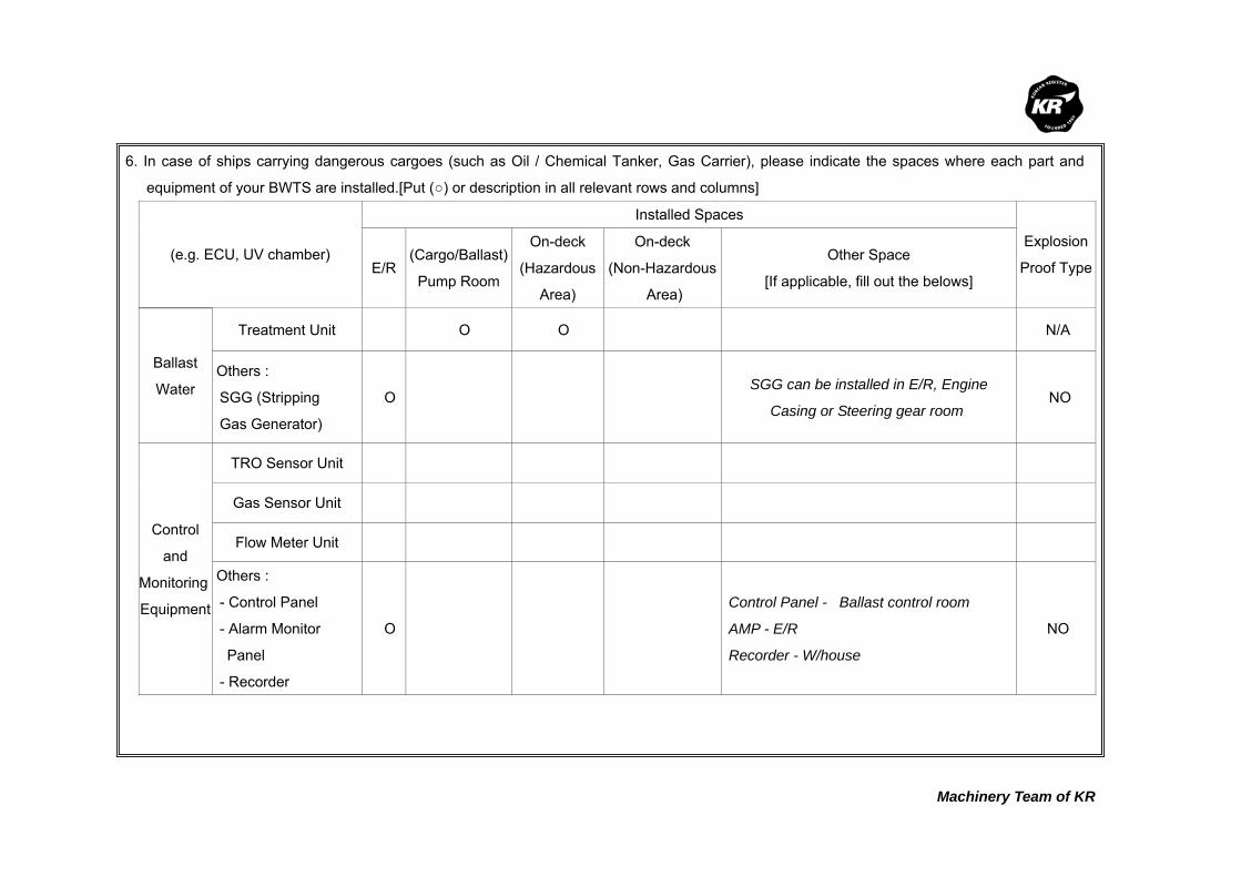
Machinery Team of KR
6. In case of ships carrying dangerous cargoes (such as Oil / Chemical Tanker, Gas Carrier), please indicate the spaces where each part and
equipment of your BWTS are installed.[Put (○) or description in all relevant rows and columns]
(e.g. ECU, UV chamber)
Installed Spaces
Explosion
Proof Type E/R(Cargo/Ballast)
Pump Room
On-deck
(Hazardous
Area)
On-deck
(Non-Hazardous
Area)
Other Space
[If applicable, fill out the belows]
Ballast
Water
Treatment Unit O O N/A
Others :
SGG (Stripping
Gas Generator)
O SGG can be installed in E/R, Engine
Casing or Steering gear room NO
Control
and
Monitoring
Equipment
TRO Sensor Unit
Gas Sensor Unit
Flow Meter Unit
Others :
- Control Panel
- Alarm Monitor
Panel
- Recorder
O
Control Panel - Ballast control room
AMP - E/R
Recorder - W/house
NO
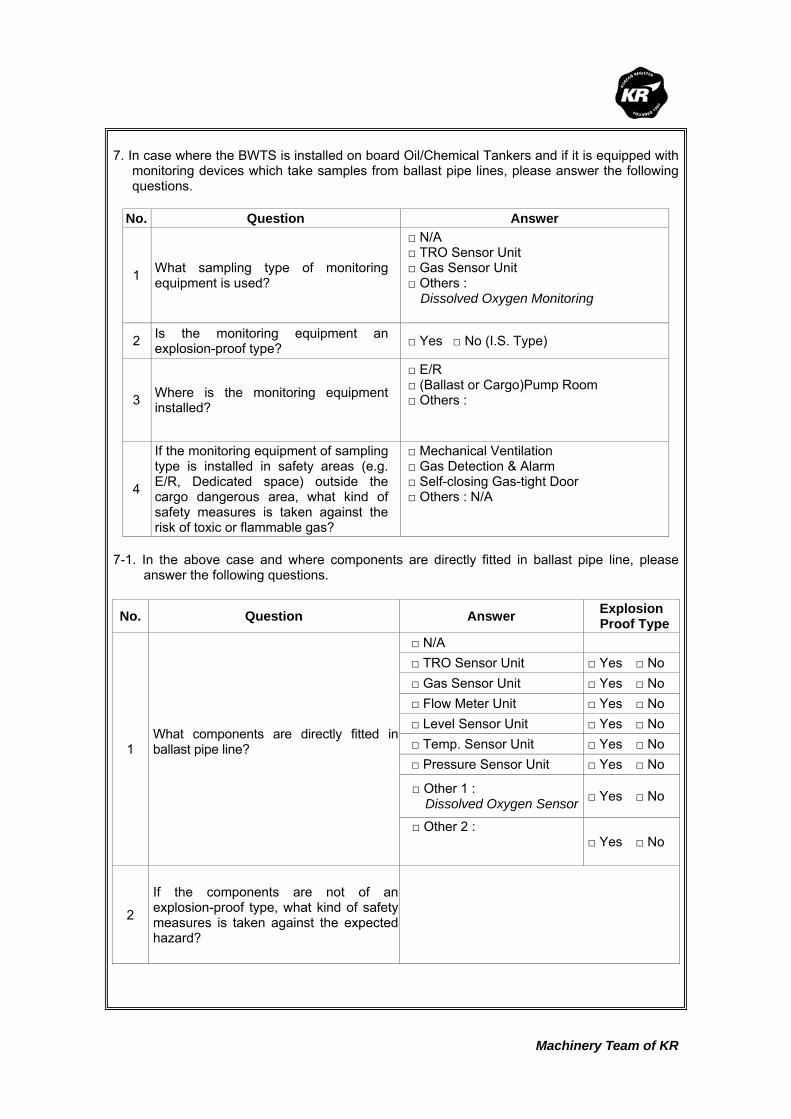
Machinery Team of KR
7. In case where the BWTS is installed on board Oil/Chemical Tankers and if it is equipped with
monitoring devices which take samples from ballast pipe lines, please answer the following questions.
No. Question Answer
1 What sampling type of monitoring equipment is used?
□ N/A □ TRO Sensor Unit □ Gas Sensor Unit □ Others : Dissolved Oxygen Monitoring
2 Is the monitoring equipment an explosion-proof type? □ Yes □ No (I.S. Type)
3 Where is the monitoring equipment installed?
□ E/R □ (Ballast or Cargo)Pump Room □ Others :
4
If the monitoring equipment of sampling type is installed in safety areas (e.g. E/R, Dedicated space) outside the cargo dangerous area, what kind of safety measures is taken against the risk of toxic or flammable gas?
□ Mechanical Ventilation □ Gas Detection & Alarm □ Self-closing Gas-tight Door □ Others : N/A
7-1. In the above case and where components are directly fitted in ballast pipe line, please
answer the following questions.
No. Question Answer Explosion Proof Type
1 What components are directly fitted in ballast pipe line?
□ N/A □ TRO Sensor Unit □ Yes □ No □ Gas Sensor Unit □ Yes □ No □ Flow Meter Unit □ Yes □ No □ Level Sensor Unit □ Yes □ No □ Temp. Sensor Unit □ Yes □ No □ Pressure Sensor Unit □ Yes □ No
□ Other 1 : Dissolved Oxygen Sensor □ Yes □ No
□ Other 2 :
□ Yes □ No
2
If the components are not of an explosion-proof type, what kind of safety measures is taken against the expected hazard?

Machinery Team of KR
8. If your BWTS uses active substances (e.g. Ozone, hydrogen peroxide), please fill in relevant
rows and columns.
No. Question Answer
1 Type of active substances (e.g. Ozone, hydrogen peroxide, etc)
(Please describe briefly)
2 Characteristics of active substances
□ Toxic □ Flammable □ Asphyxiant □ Others :
3 What means are provided to protect crews from the leak of active substances ?
□ Gas Detection □ Mechanical Vent □ None □ Others :
4 Where is the generating unit of active substances installed on board ship ?
□ E/R □ Pump Room □ Dedicated space □ Others :
5 Is ventilation unit to be provided to the location where the BWTS is installed ?
□ Mechanical Vent. (Air change rate : /H) □ Natural Vent. □ None □ Others :
6 What measures are considered to protect the supplying pipe of active substances ?
□ Use double pipes □ Use the stainless steel □ Use all welding joints □ Others :
9. Are any measures put in place for the case where the volume of ballast water exceeds the
maximum rated capacity of the BWTS ? (e.g; Alarm, Automatic shut-down, Auto slow down, etc.) This system controls ballast water flow rate by using a Throttle valve inside the Venturi
Injector. 10. Does your BWTS have any redundancy for essential equipment and parts (e.g. TRO
sensing units, flow meter unit, etc) to keep the system running in case of failure ? The system is equipped with 2 sets of air blowers (each 50% of system requirement)

Machinery Team of KR
11. Where are the spaces that you recommend to install sampling equipment according to BWM
Convention/Guideline G2 ? (e.g; Ballast Water Discharge Line, etc.) Sounding pipe 12. Regarding the bi-products that are generated from the ballast water treatment process,
please fill in all relevant rows. No. Question Answer
1 Are dangerous gases generated as by-products after ballast water treatment process?
□ Yes □ No
2 What type of dangerous gases is generated? (e.g; Hydrogen, chlorine, etc.)
Low Oxygen Inert Gas (N2, CO2)
3 What are properties of the by- product?
□ Toxic □ Flammable □ Asphyxiant □ Others :
4
What is the generation rate of dangerous gasesper each type of BWTS ? (e.g. 1m3/hr, etc) Please use a separate sheet if needed.
Ballast pump design capacity X 1.25
5 Is the gas detection unit an explosion-proof type? □ Yes □ No
6
Where are the residue gases ventilated to aftergas detection? (e.g. installation location of the gas detection unit,or safety area on the exposed weather deck)
N/A

Machinery Team of KR
Korean Register of Shipping, with the objective of GLOBAL TOP+, will always do our best
to provide the costumers with quicker and better quality services.
As the implementation of the Ballast Water Management Convention is imminent,
consideration is being given to the ship's design changes in relation to the installation of
Ballast Water Treatment System (hereinafter referred to as 'BWTS'), which is now put in
place on board some new ships.
The Machinery Team of this Society is planning to publish a Guidance for Installation of the
BWTS.
The KR's BWTS Guidance is intended to assist shipyards and ship owners in selecting
appropriate BWTS by describing the physical and mechanical properties of the BWTS,
technical aspects to be considered at the time of installation, and specific considerations
per each ship type.
In order for us to be able to complete the BWTS Guidance, we would highly appreciate it if
you could fill the questionnaire in as much as possible, and submit to us the completed
questionnaire by 30 April 2011 at the latest.
Your responses to the questionnaire are required for guidance purposes only and will not
be disclosed partly or wholly if specifically requested by the respondents.
Oh Joo-won / General Manager of Machinery Team
Korean Register of Shipping Please return completed questionnaire to ; Fax : +82 42-862-6016 E-mail : [email protected] (Contact : Jang Jae-shik, +82-42-869-9456)
Questionnaire about
Ballast Water Treatment System

Machinery Team of KR
Thank you for participating in the BWTS Guidance questionnaire. If you have any questions
about how to complete it, please contact Jang Jae-shik, KR Machinery Team by phone: +82-42-
869-9456 or E-mail: [email protected]
1. Please describe about your company
Company name HYUDAI HEAVY INDUSTRY CO., LTD
Person in Charge Kim, Ha Jong
Telephone No. 052-202-6327
Fax. No. 052-202-6330
E-mail [email protected]
2. Please describe briefly about the Ballast Water Treatment System(hereinafter referred to as
'BWTS') manufactured by your company.
1) Product Name : HiBallast
2) Treatment Type (e.g. electrolysis, UV, ozone, ozone+electrolysis, etc.) :
Electrolysis type
During ballasting operation, filter unit removes particles or organisms larger than 50 ㎛
and disinfectant produced by Electrolysis Unit is injected to the main ballast pipe to kill
micro-organisms in ballast water.
3) In which process does the ballast water treatment occur ?
Treatment process Put a mark(○) in the relevant row
Ballasting O (Neutralization during de-ballasting)
De-ballasting
Ballasting and De-ballasting
In the ballast tank
Others
(describe in detail)
3. Please list strengths of your BWTS.
1) Low cost
2) Easy to install
3) Easy to maintenance
4) Low electric power consumption
5) Automatic and remote control using PLC

Machinery Team of KR
4. Please describe what needs to be specially considered when your BWTS is installed on
board ships.
1) To install a booster pump for the operation of the system.
2) Not suitable for hazardous area (Explosion proof type to be developed later)
3) Require a mechanical vent. system
5. Please fill in all applicable columns of the following table about the power consumption and
the required space.
Treatment Capacity (m3/h) Power Consumption(kW) Required Space (L x B x H)m
100
200
300 < 33 kW
400
500 < 48 kW
600 4000x3500x2000
700
800
900
1000 < 92 kW 4000x3500x2000
1500 < 133 kW
2000 < 176 kW 7000x3500x2000
2500 < 216 kW
3000
3500
4000
4500
5000 < 430 kW 8000x3500x2000
6000 < 507 kW
7000
Others :
* Base on the maximum electric consumption of each system
* Models with blank spaces are under development.

Machinery Team of KR
6. In case of ships carrying dangerous cargoes (such as Oil / Chemical Tanker, Gas Carrier), please indicate the spaces where each part and
equipment of your BWTS are installed.[Put (○) or description in all relevant rows and columns]
(e.g. ECU, UV chamber)
Installed Spaces
Explosion
Proof Type E/R(Cargo/Ballast)
Pump Room
On-deck
(Hazardous
Area)
On-deck
(Non-Hazardous
Area)
Other Space
[If applicable, fill out the belows]
Ballast
Water
Treatment
Equipment
Treatment Unit O NO
Neutralization Unit O NO
Others : (PDE, PRE),
Sampling Tank O NO
Control
and
Monitoring
Equipment
TRO Sensor Unit O NO
Gas Sensor Unit O Yes
Conductivity Sensor
Unit N/A NO
Flow Meter Unit N/A NO
Others :
(LOP, AVU) O NO
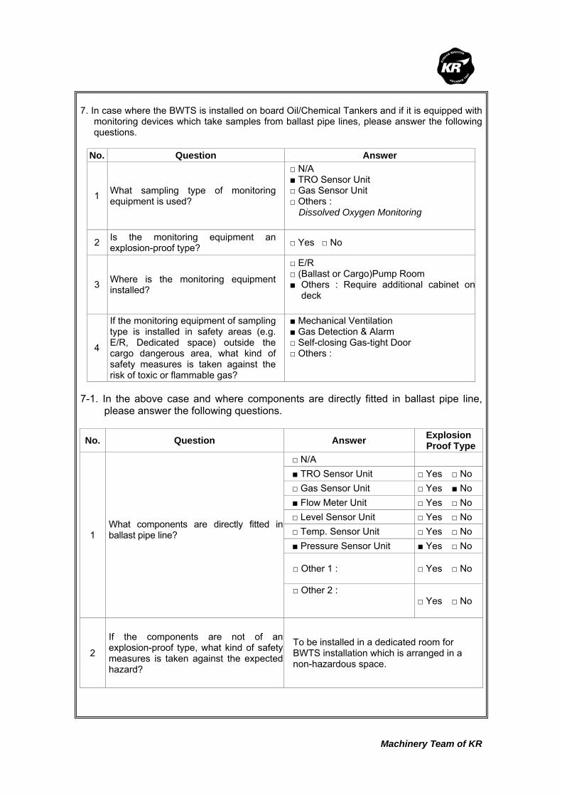
Machinery Team of KR
7. In case where the BWTS is installed on board Oil/Chemical Tankers and if it is equipped with
monitoring devices which take samples from ballast pipe lines, please answer the following questions.
No. Question Answer
1 What sampling type of monitoring equipment is used?
□ N/A ■ TRO Sensor Unit □ Gas Sensor Unit □ Others : Dissolved Oxygen Monitoring
2 Is the monitoring equipment an explosion-proof type? □ Yes □ No
3 Where is the monitoring equipment installed?
□ E/R □ (Ballast or Cargo)Pump Room ■ Others : Require additional cabinet on
deck
4
If the monitoring equipment of sampling type is installed in safety areas (e.g. E/R, Dedicated space) outside the cargo dangerous area, what kind of safety measures is taken against the risk of toxic or flammable gas?
■ Mechanical Ventilation ■ Gas Detection & Alarm □ Self-closing Gas-tight Door □ Others :
7-1. In the above case and where components are directly fitted in ballast pipe line,
please answer the following questions.
No. Question Answer Explosion Proof Type
1 What components are directly fitted in ballast pipe line?
□ N/A ■ TRO Sensor Unit □ Yes □ No □ Gas Sensor Unit □ Yes ■ No ■ Flow Meter Unit □ Yes □ No □ Level Sensor Unit □ Yes □ No □ Temp. Sensor Unit □ Yes □ No ■ Pressure Sensor Unit ■ Yes □ No
□ Other 1 : □ Yes □ No
□ Other 2 :
□ Yes □ No
2
If the components are not of an explosion-proof type, what kind of safety measures is taken against the expected hazard?
To be installed in a dedicated room for BWTS installation which is arranged in a non-hazardous space.
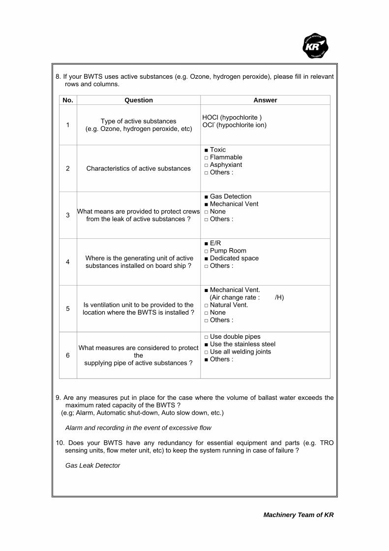
Machinery Team of KR
8. If your BWTS uses active substances (e.g. Ozone, hydrogen peroxide), please fill in relevant
rows and columns.
No. Question Answer
1 Type of active substances (e.g. Ozone, hydrogen peroxide, etc)
HOCl (hypochlorite ) OCl- (hypochlorite ion)
2 Characteristics of active substances
■ Toxic □ Flammable □ Asphyxiant □ Others :
3 What means are provided to protect crews from the leak of active substances ?
■ Gas Detection ■ Mechanical Vent □ None □ Others :
4 Where is the generating unit of active substances installed on board ship ?
■ E/R □ Pump Room ■ Dedicated space □ Others :
5 Is ventilation unit to be provided to the location where the BWTS is installed ?
■ Mechanical Vent. (Air change rate : /H) □ Natural Vent. □ None □ Others :
6 What measures are considered to protect
the supplying pipe of active substances ?
□ Use double pipes ■ Use the stainless steel □ Use all welding joints ■ Others :
9. Are any measures put in place for the case where the volume of ballast water exceeds the
maximum rated capacity of the BWTS ? (e.g; Alarm, Automatic shut-down, Auto slow down, etc.) Alarm and recording in the event of excessive flow 10. Does your BWTS have any redundancy for essential equipment and parts (e.g. TRO
sensing units, flow meter unit, etc) to keep the system running in case of failure ? Gas Leak Detector
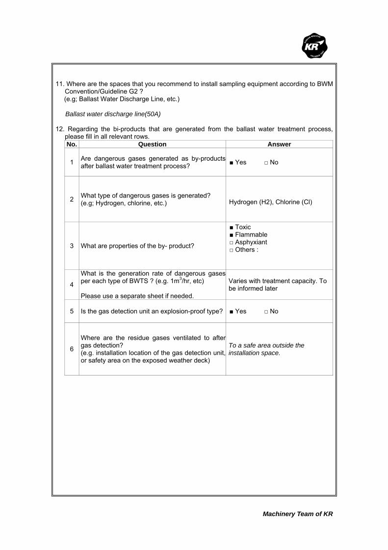
Machinery Team of KR
11. Where are the spaces that you recommend to install sampling equipment according to BWM
Convention/Guideline G2 ? (e.g; Ballast Water Discharge Line, etc.) Ballast water discharge line(50A) 12. Regarding the bi-products that are generated from the ballast water treatment process,
please fill in all relevant rows. No. Question Answer
1 Are dangerous gases generated as by-products after ballast water treatment process?
■ Yes □ No
2 What type of dangerous gases is generated? (e.g; Hydrogen, chlorine, etc.)
Hydrogen (H2), Chlorine (Cl)
3 What are properties of the by- product?
■ Toxic ■ Flammable □ Asphyxiant □ Others :
4
What is the generation rate of dangerous gasesper each type of BWTS ? (e.g. 1m3/hr, etc) Please use a separate sheet if needed.
Varies with treatment capacity. To be informed later
5 Is the gas detection unit an explosion-proof type? ■ Yes □ No
6
Where are the residue gases ventilated to aftergas detection? (e.g. installation location of the gas detection unit,or safety area on the exposed weather deck)
To a safe area outside the installation space.

Machinery Team of KR
Korean Register of Shipping, with the objective of GLOBAL TOP+, will always do our best
to provide the costumers with quicker and better quality services.
As the implementation of the Ballast Water Management Convention is imminent,
consideration is being given to the ship's design changes in relation to the installation of
Ballast Water Treatment System (hereinafter referred to as 'BWTS'), which is now put in
place on board some new ships.
The Machinery Team of this Society is planning to publish a Guidance for Installation of the
BWTS.
The KR's BWTS Guidance is intended to assist shipyards and ship owners in selecting
appropriate BWTS by describing the physical and mechanical properties of the BWTS,
technical aspects to be considered at the time of installation, and specific considerations
per each ship type.
In order for us to be able to complete the BWTS Guidance, we would highly appreciate it if
you could fill the questionnaire in as much as possible, and submit to us the completed
questionnaire by 30 April 2011 at the latest.
Your responses to the questionnaire are required for guidance purposes only and will not
be disclosed partly or wholly if specifically requested by the respondents.
Oh Joo-won / General Manager of Machinery Team
Korean Register of Shipping Please return completed questionnaire to ; Fax : +82 42-862-6016 E-mail : [email protected] (Contact : Jang Jae-shik, +82-42-869-9456)
Questionnaire about
Ballast Water Treatment System
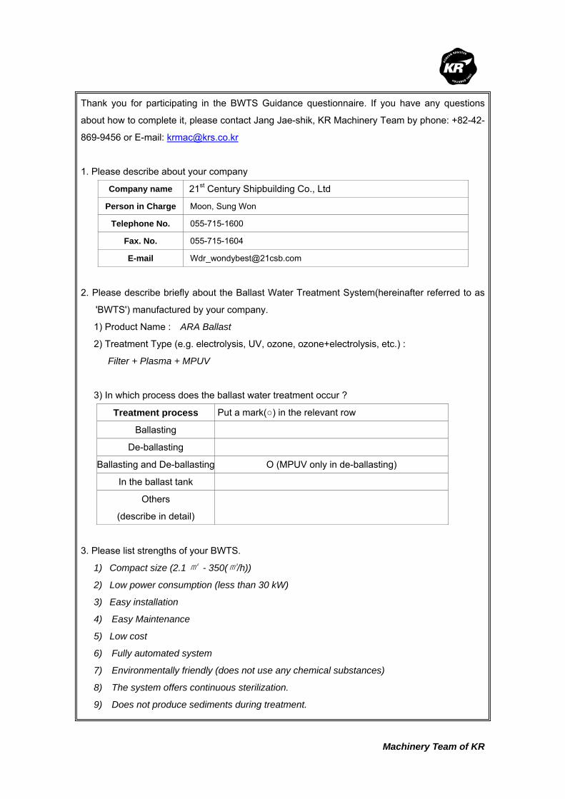
Machinery Team of KR
Thank you for participating in the BWTS Guidance questionnaire. If you have any questions
about how to complete it, please contact Jang Jae-shik, KR Machinery Team by phone: +82-42-
869-9456 or E-mail: [email protected]
1. Please describe about your company
Company name 21st Century Shipbuilding Co., Ltd
Person in Charge Moon, Sung Won
Telephone No. 055-715-1600
Fax. No. 055-715-1604
E-mail [email protected]
2. Please describe briefly about the Ballast Water Treatment System(hereinafter referred to as
'BWTS') manufactured by your company.
1) Product Name : ARA Ballast
2) Treatment Type (e.g. electrolysis, UV, ozone, ozone+electrolysis, etc.) :
Filter + Plasma + MPUV
3) In which process does the ballast water treatment occur ?
Treatment process Put a mark(○) in the relevant row
Ballasting
De-ballasting
Ballasting and De-ballasting O (MPUV only in de-ballasting)
In the ballast tank
Others
(describe in detail)
3. Please list strengths of your BWTS.
1) Compact size (2.1 ㎡ - 350(㎥/h))
2) Low power consumption (less than 30 kW)
3) Easy installation
4) Easy Maintenance
5) Low cost
6) Fully automated system
7) Environmentally friendly (does not use any chemical substances)
8) The system offers continuous sterilization.
9) Does not produce sediments during treatment.

Machinery Team of KR
4. Please describe what needs to be specially considered when your BWTS is installed on
board ships.
1) Select a model according to the treatment capacity.
2) Check installation space to verify whether the system need to explosion-proof type or not
5. Please fill in all applicable columns of the following table about the power consumption and
the required space.
Model of system Flow rate
(m3/h)
Power
consumption(kW) Footprint
Dimension summary
(L x B x H)㎜
ARA-350 350 30 1.79㎡ 1860 x 964 x 1865
ARA-500 500 60 2.74㎡ 2650 x 1035 x 2540
ARA-750 750 85 2.78㎡ 2684 x 1035 x 2540
ARA-1000 1000 125 5.06㎡ 4098 x 1235 x 2680
ARA-1500 1500 170 5.19㎡ 4204 x 1235 x 2875
ARA-2000 2000 250 10.12㎡ 4098 x 2470 x 2680
ARA-3000 3000 350 10.38㎡ 4204 x 2470 x 2875
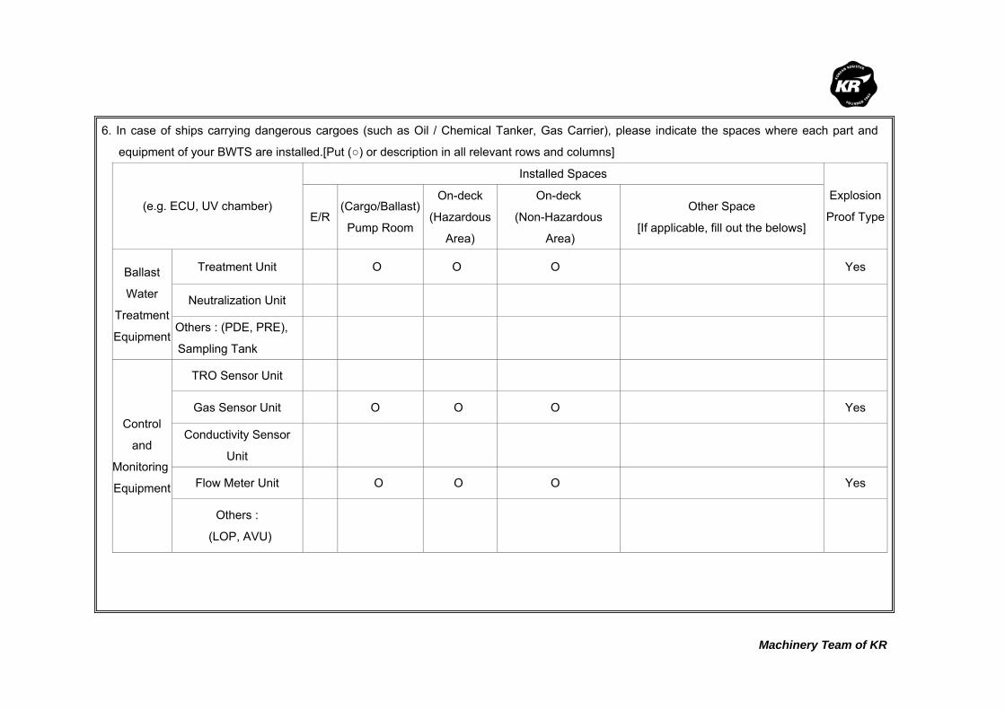
Machinery Team of KR
6. In case of ships carrying dangerous cargoes (such as Oil / Chemical Tanker, Gas Carrier), please indicate the spaces where each part and
equipment of your BWTS are installed.[Put (○) or description in all relevant rows and columns]
(e.g. ECU, UV chamber)
Installed Spaces
Explosion
Proof Type E/R(Cargo/Ballast)
Pump Room
On-deck
(Hazardous
Area)
On-deck
(Non-Hazardous
Area)
Other Space
[If applicable, fill out the belows]
Ballast
Water
Treatment
Equipment
Treatment Unit O O O Yes
Neutralization Unit
Others : (PDE, PRE),
Sampling Tank
Control
and
Monitoring
Equipment
TRO Sensor Unit
Gas Sensor Unit O O O Yes
Conductivity Sensor
Unit
Flow Meter Unit O O O Yes
Others :
(LOP, AVU)

Machinery Team of KR
7. In case where the BWTS is installed on board Oil/Chemical Tankers and if it is equipped with
monitoring devices which take samples from ballast pipe lines, please answer the following questions.
No. Question Answer
1 What sampling type of monitoring equipment is used?
□ N/A □ TRO Sensor Unit ■ Gas Sensor Unit ■ Others : Dissolved Oxygen Monitoring
2 Is the monitoring equipment an explosion-proof type? ■ Yes □ No
3 Where is the monitoring equipment installed?
■ E/R □ (Ballast or Cargo)Pump Room ■ Others : ECR, CCR, Up Decker
4
If the monitoring equipment of sampling type is installed in safety areas (e.g. E/R, Dedicated space) outside the cargo dangerous area, what kind of safety measures is taken against the risk of toxic or flammable gas?
■ Mechanical Ventilation ■ Gas Detection & Alarm ■ Self-closing Gas-tight Door □ Others :
7-1. In the above case and where components are directly fitted in ballast pipe line,
please answer the following questions.
No. Question Answer Explosion Proof Type
1 What components are directly fitted in ballast pipe line?
□ N/A □ TRO Sensor Unit □ Yes □ No ■ Gas Sensor Unit ■ Yes □ No ■ Flow Meter Unit ■ Yes □ No ■ Level Sensor Unit ■ Yes □ No ■ Temp. Sensor Unit ■ Yes □ No ■ Pressure Sensor Unit ■ Yes □ No
□ Other 1 : Throttle valve ■ Yes □ No
□ Other 2 :
□ Yes □ No
2
If the components are not of an explosion-proof type, what kind of safety measures is taken against the expected hazard?
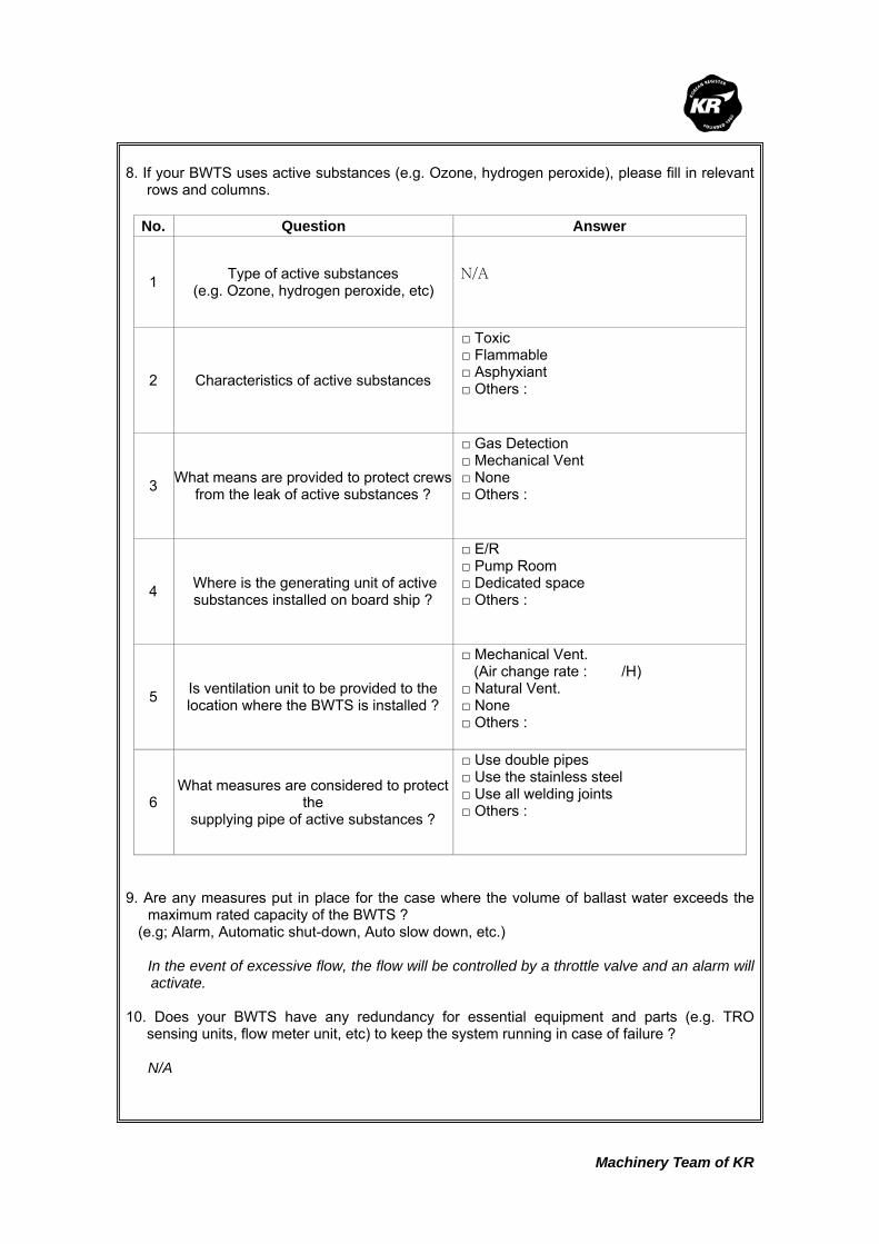
Machinery Team of KR
8. If your BWTS uses active substances (e.g. Ozone, hydrogen peroxide), please fill in relevant
rows and columns.
No. Question Answer
1 Type of active substances (e.g. Ozone, hydrogen peroxide, etc)
N/A
2 Characteristics of active substances
□ Toxic □ Flammable □ Asphyxiant □ Others :
3 What means are provided to protect crews from the leak of active substances ?
□ Gas Detection □ Mechanical Vent □ None □ Others :
4 Where is the generating unit of active substances installed on board ship ?
□ E/R □ Pump Room □ Dedicated space □ Others :
5 Is ventilation unit to be provided to the location where the BWTS is installed ?
□ Mechanical Vent. (Air change rate : /H) □ Natural Vent. □ None □ Others :
6 What measures are considered to protect
the supplying pipe of active substances ?
□ Use double pipes □ Use the stainless steel □ Use all welding joints □ Others :
9. Are any measures put in place for the case where the volume of ballast water exceeds the
maximum rated capacity of the BWTS ? (e.g; Alarm, Automatic shut-down, Auto slow down, etc.) In the event of excessive flow, the flow will be controlled by a throttle valve and an alarm will
activate. 10. Does your BWTS have any redundancy for essential equipment and parts (e.g. TRO
sensing units, flow meter unit, etc) to keep the system running in case of failure ? N/A

Machinery Team of KR
11. Where are the spaces that you recommend to install sampling equipment according to BWM
Convention/Guideline G2 ? (e.g; Ballast Water Discharge Line, etc.) At suction side of a filter and ballast water discharge line. 12. Regarding the bi-products that are generated from the ballast water treatment process,
please fill in all relevant rows. No. Question Answer
1 Are dangerous gases generated as by-products after ballast water treatment process?
□ Yes ■ No
2 What type of dangerous gases is generated? (e.g; Hydrogen, chlorine, etc.)
Low Oxygen Inert Gas (N2, CO2)
3 What are properties of the by- product?
□ Toxic □ Flammable □ Asphyxiant □ Others :
4
What is the generation rate of dangerous gasesper each type of BWTS ? (e.g. 1m3/hr, etc) Please use a separate sheet if needed.
5 Is the gas detection unit an explosion-proof type? □ Yes □ No
6
Where are the residue gases ventilated to aftergas detection? (e.g. installation location of the gas detection unit,or safety area on the exposed weather deck)
Machinery Team of KR
Korean Register of Shipping, with the objective of GLOBAL TOP+, will always do our best
to provide the costumers with quicker and better quality services.
As the implementation of the Ballast Water Management Convention is imminent,
consideration is being given to the ship's design changes in relation to the installation of
Ballast Water Treatment System (hereinafter referred to as 'BWTS'), which is now put in
place on board some new ships.
The Machinery Team of this Society is planning to publish a Guidance for Installation of the
BWTS.
The KR's BWTS Guidance is intended to assist shipyards and ship owners in selecting
appropriate BWTS by describing the physical and mechanical properties of the BWTS,
technical aspects to be considered at the time of installation, and specific considerations
per each ship type.
In order for us to be able to complete the BWTS Guidance, we would highly appreciate it if
you could fill the questionnaire in as much as possible, and submit to us the completed
questionnaire by 30 April 2011 at the latest.
Your responses to the questionnaire are required for guidance purposes only and will not
be disclosed partly or wholly if specifically requested by the respondents.
Oh Joo-won / General Manager of Machinery Team
Korean Register of Shipping
Please return completed questionnaire to ; Fax : +82 42-862-6016 E-mail : [email protected] (Contact : Jang Jae-shik, +82-42-869-9456)
Questionnaire about
Ballast Water Treatment System
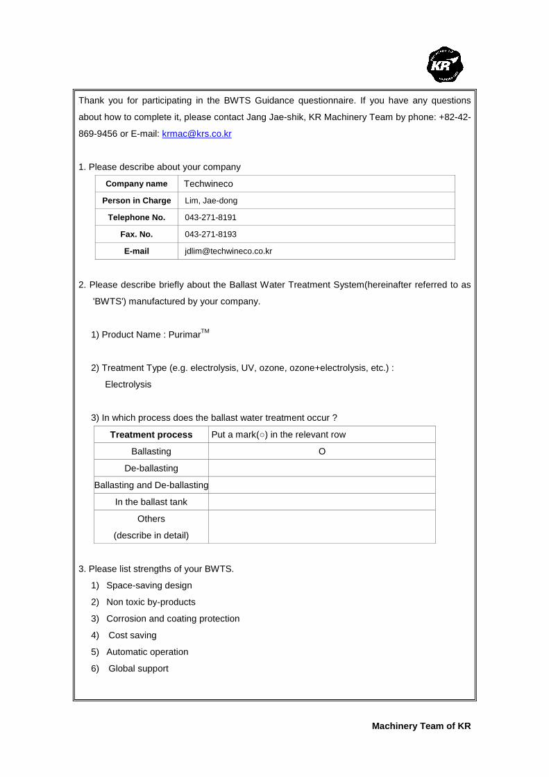
Machinery Team of KR
Thank you for participating in the BWTS Guidance questionnaire. If you have any questions
about how to complete it, please contact Jang Jae-shik, KR Machinery Team by phone: +82-42-
869-9456 or E-mail: [email protected]
1. Please describe about your company
Company name Techwineco
Person in Charge Lim, Jae-dong
Telephone No. 043-271-8191
Fax. No. 043-271-8193
E-mail [email protected]
2. Please describe briefly about the Ballast Water Treatment System(hereinafter referred to as
'BWTS') manufactured by your company.
1) Product Name : PurimarTM
2) Treatment Type (e.g. electrolysis, UV, ozone, ozone+electrolysis, etc.) :
Electrolysis
3) In which process does the ballast water treatment occur ?
Treatment process Put a mark(○) in the relevant row
Ballasting O
De-ballasting
Ballasting and De-ballasting
In the ballast tank
Others
(describe in detail)
3. Please list strengths of your BWTS.
1) Space-saving design
2) Non toxic by-products
3) Corrosion and coating protection
4) Cost saving
5) Automatic operation
6) Global support

Machinery Team of KR
4. Please describe what needs to be specially considered when your BWTS is installed on
board ships.
1) Explosion-proof type should be considered when installed in pump room.
2) Vent pipes for Hydrogen gas should be installed in a safe space.
5. Please fill in all applicable columns of the following table about the power consumption and
the required space.
Install dimension and weight
Electrolysis Unit Neutralization Unit Sensor Unit No.
Flow
Rate
(m3/h) Dimension
(LxWxH)
Weight
(Kg)
Dimension
(¢xH)
Weight
(Kg)
Dimension
(LxWxH)
Weight
(Kg)
Power
Consumption
(kW)
1 200 1950x1530x1800 900 1100x1400 60 900x300x1600 80 14.4
2 500 2000x2000x2050 1030 1400x1900 150 900x300x1600 80 25.6
3 700 2150x2000x2040 1120 1500x2100 210 900x300x1600 80 32.5
4 1,000 2600x2400x2130 1610 1700x2200 300 900x300x1600 80 46.9
5 1,500 2800x2500x2400 1850 2000x2500 450 900x300x1600 80 64.2
6 2,000 3100x2600x2560 2390 2100x2800 600 900x300x1600 80 81.5
7 2,500 3200x2600x2560 2600 2200x2500 750 900x300x1600 80 99.6
8 3,000 3300x2700x2600 3120 2400x2800 900 900x300x1600 80 117.0
9 3,500 4300x2900x2650 3640 2500x3500 1050 900x300x1600 80 134.3
10 4,000 4600x3200x2700 3930 2600x3200 1200 900x300x1600 80 151.6
11 4,500 4650x3300x2800 4500 2700x3200 13510 900x300x1600 80 168.9
12 5,000 4700x3300x2800 4830 2800x3200 1500 900x300x1600 80 188.3
13 6,000 5000x3300x3000 5550 3000x3300 1800 900x300x1600 80 223.7
14 7,000 5200x3500x3200 6000 3000x4000 2100 900x300x1600 80 258.3
* Power consumption for auto back-flush pump not included.

Machinery Team of KR
6. In case of ships carrying dangerous cargoes (such as Oil / Chemical Tanker, Gas Carrier), please indicate the spaces where each part and
equipment of your BWTS are installed.[Put (○) or description in all relevant rows and columns]
Installed Spaces
(e.g. ECU, UV chamber) E/R
(Cargo/Ballast)
Pump Room
On-deck
(Hazardous
Area)
On-deck
(Non-Hazardous
Area)
Other Space
[If applicable, fill out the belows]
Explosion
Proof Type
Treatment Unit O O No
Neutralization Unit O O O O Yes
Ballast
Water
Treatment
Equipment Others : Filter O O Yes
TRO Sensor Unit O O O O Yes
Gas Sensor Unit O O Yes
Conductivity Sensor
Unit O O Yes
Flow Meter Unit O O O Yes
Control
and
Monitoring
Equipment
Others :
Control Panel O O
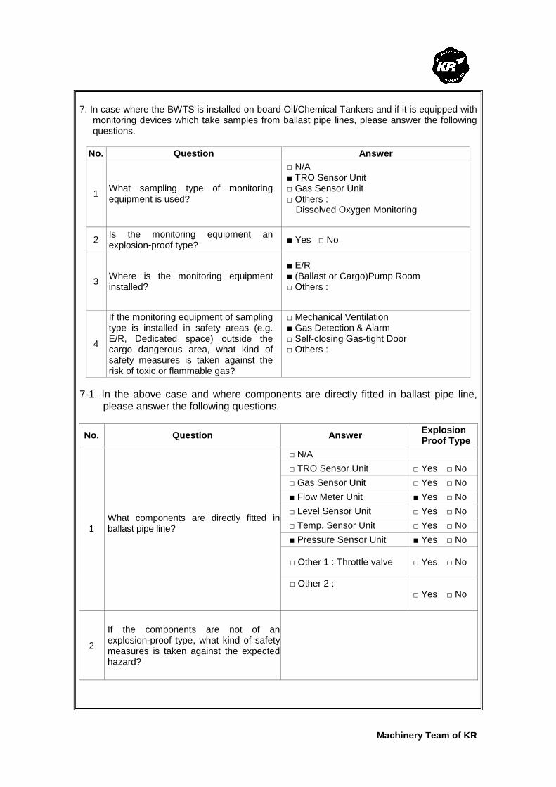
Machinery Team of KR
7. In case where the BWTS is installed on board Oil/Chemical Tankers and if it is equipped with
monitoring devices which take samples from ballast pipe lines, please answer the following questions.
No. Question Answer
1 What sampling type of monitoring equipment is used?
□ N/A ■ TRO Sensor Unit □ Gas Sensor Unit □ Others : Dissolved Oxygen Monitoring
2 Is the monitoring equipment an explosion-proof type?
■ Yes □ No
3 Where is the monitoring equipment installed?
■ E/R ■ (Ballast or Cargo)Pump Room □ Others :
4
If the monitoring equipment of sampling type is installed in safety areas (e.g. E/R, Dedicated space) outside the cargo dangerous area, what kind of safety measures is taken against the risk of toxic or flammable gas?
□ Mechanical Ventilation ■ Gas Detection & Alarm □ Self-closing Gas-tight Door □ Others :
7-1. In the above case and where components are directly fitted in ballast pipe line,
please answer the following questions.
No. Question Answer Explosion
Proof Type
□ N/A
□ TRO Sensor Unit □ Yes □ No
□ Gas Sensor Unit □ Yes □ No
■ Flow Meter Unit ■ Yes □ No
□ Level Sensor Unit □ Yes □ No
□ Temp. Sensor Unit □ Yes □ No
■ Pressure Sensor Unit ■ Yes □ No
□ Other 1 : Throttle valve □ Yes □ No
1 What components are directly fitted in ballast pipe line?
□ Other 2 :
□ Yes □ No
2
If the components are not of an explosion-proof type, what kind of safety measures is taken against the expected hazard?
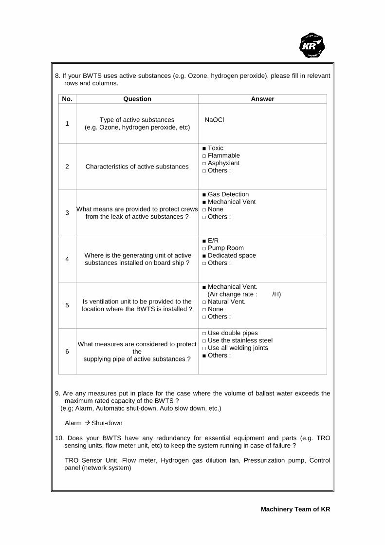
Machinery Team of KR
8. If your BWTS uses active substances (e.g. Ozone, hydrogen peroxide), please fill in relevant
rows and columns.
No. Question Answer
1 Type of active substances
(e.g. Ozone, hydrogen peroxide, etc) NaOCl
2 Characteristics of active substances
■ Toxic □ Flammable □ Asphyxiant □ Others :
3 What means are provided to protect crews
from the leak of active substances ?
■ Gas Detection ■ Mechanical Vent □ None □ Others :
4 Where is the generating unit of active substances installed on board ship ?
■ E/R □ Pump Room ■ Dedicated space □ Others :
5 Is ventilation unit to be provided to the location where the BWTS is installed ?
■ Mechanical Vent. (Air change rate : /H) □ Natural Vent. □ None □ Others :
6 What measures are considered to protect
the supplying pipe of active substances ?
□ Use double pipes □ Use the stainless steel □ Use all welding joints ■ Others :
9. Are any measures put in place for the case where the volume of ballast water exceeds the
maximum rated capacity of the BWTS ? (e.g; Alarm, Automatic shut-down, Auto slow down, etc.) Alarm � Shut-down 10. Does your BWTS have any redundancy for essential equipment and parts (e.g. TRO
sensing units, flow meter unit, etc) to keep the system running in case of failure ? TRO Sensor Unit, Flow meter, Hydrogen gas dilution fan, Pressurization pump, Control
panel (network system)

Machinery Team of KR
11. Where are the spaces that you recommend to install sampling equipment according to BWM
Convention/Guideline G2 ? (e.g; Ballast Water Discharge Line, etc.) Ballast water discharge Line, Over board line 12. Regarding the bi-products that are generated from the ballast water treatment process,
please fill in all relevant rows.
No. Question Answer
1 Are dangerous gases generated as by-products after ballast water treatment process?
■ Yes □ No
2 What type of dangerous gases is generated? (e.g; Hydrogen, chlorine, etc.)
Hydrogen, Chlorine
3 What are properties of the by- product?
■ Toxic ■ Flammable □ Asphyxiant □ Others :
4
What is the generation rate of dangerous gases per each type of BWTS ? (e.g. 1m3/hr, etc) Please use a separate sheet if needed.
Under 2%
5 Is the gas detection unit an explosion-proof type? ■ Yes □ No
6
Where are the residue gases ventilated to after gas detection? (e.g. installation location of the gas detection unit, or safety area on the exposed weather deck)
Safe area on upper deck

Machinery Team of KR
Korean Register of Shipping, with the objective of GLOBAL TOP+, will always do our best
to provide the costumers with quicker and better quality services.
As the implementation of the Ballast Water Management Convention is imminent,
consideration is being given to the ship's design changes in relation to the installation of
Ballast Water Treatment System (hereinafter referred to as 'BWTS'), which is now put in
place on board some new ships.
The Machinery Team of this Society is planning to publish a Guidance for Installation of the
BWTS.
The KR's BWTS Guidance is intended to assist shipyards and ship owners in selecting
appropriate BWTS by describing the physical and mechanical properties of the BWTS,
technical aspects to be considered at the time of installation, and specific considerations
per each ship type.
In order for us to be able to complete the BWTS Guidance, we would highly appreciate it if
you could fill the questionnaire in as much as possible, and submit to us the completed
questionnaire by 30 April 2011 at the latest.
Your responses to the questionnaire are required for guidance purposes only and will not
be disclosed partly or wholly if specifically requested by the respondents.
Oh Joo-won / General Manager of Machinery Team
Korean Register of Shipping
Please return completed questionnaire to ; Fax : +82 42-862-6016 E-mail : [email protected] (Contact : Jang Jae-shik, +82-42-869-9456)
Questionnaire about
Ballast Water Treatment System
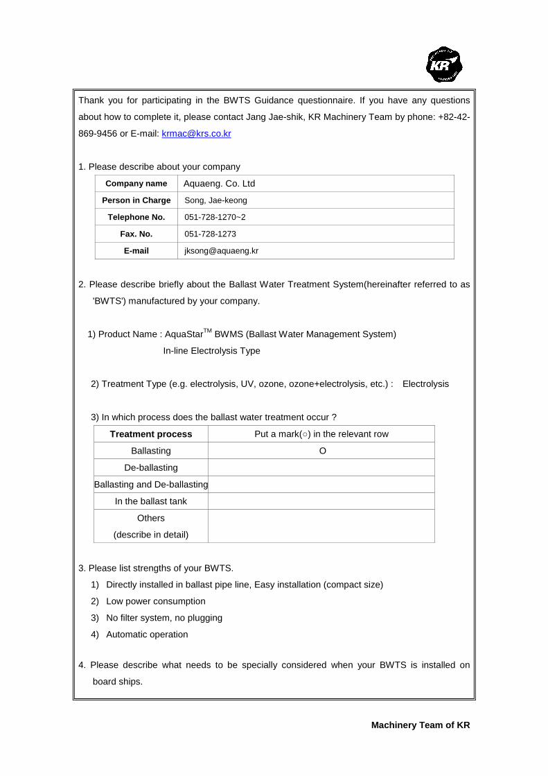
Machinery Team of KR
Thank you for participating in the BWTS Guidance questionnaire. If you have any questions
about how to complete it, please contact Jang Jae-shik, KR Machinery Team by phone: +82-42-
869-9456 or E-mail: [email protected]
1. Please describe about your company
Company name Aquaeng. Co. Ltd
Person in Charge Song, Jae-keong
Telephone No. 051-728-1270~2
Fax. No. 051-728-1273
E-mail [email protected]
2. Please describe briefly about the Ballast Water Treatment System(hereinafter referred to as
'BWTS') manufactured by your company.
1) Product Name : AquaStarTM BWMS (Ballast Water Management System)
In-line Electrolysis Type
2) Treatment Type (e.g. electrolysis, UV, ozone, ozone+electrolysis, etc.) : Electrolysis
3) In which process does the ballast water treatment occur ?
Treatment process Put a mark(○) in the relevant row
Ballasting O
De-ballasting
Ballasting and De-ballasting
In the ballast tank
Others
(describe in detail)
3. Please list strengths of your BWTS.
1) Directly installed in ballast pipe line, Easy installation (compact size)
2) Low power consumption
3) No filter system, no plugging
4) Automatic operation
4. Please describe what needs to be specially considered when your BWTS is installed on
board ships.
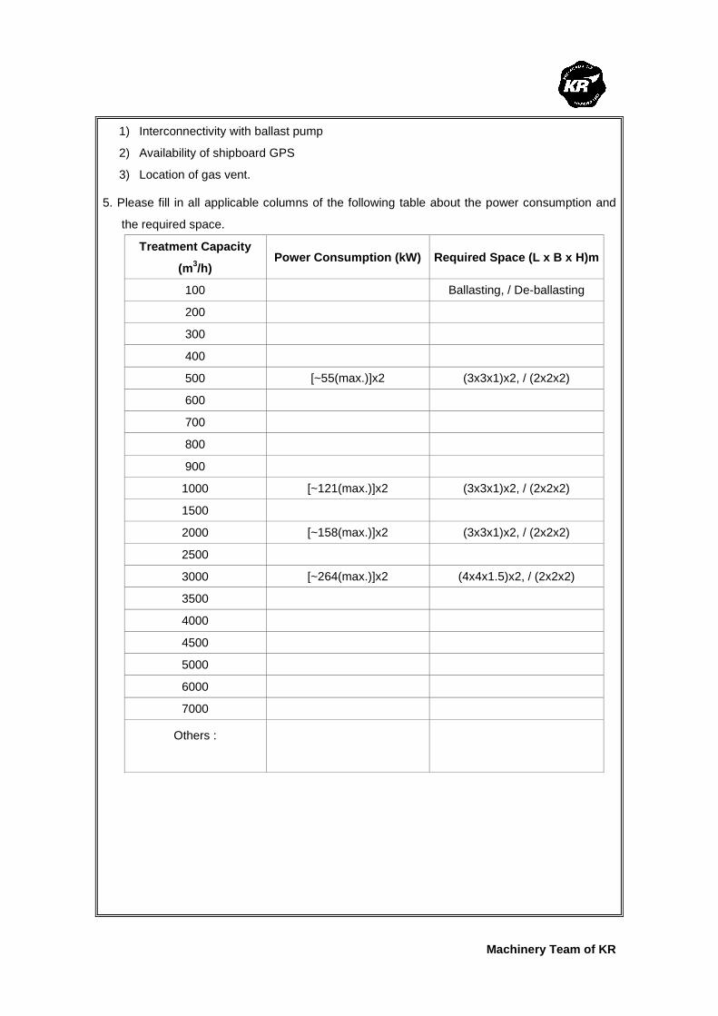
Machinery Team of KR
1) Interconnectivity with ballast pump
2) Availability of shipboard GPS
3) Location of gas vent.
5. Please fill in all applicable columns of the following table about the power consumption and
the required space.
Treatment Capacity
(m3/h) Power Consumption (kW) Required Space (L x B x H)m
100 Ballasting, / De-ballasting
200
300
400
500 [~55(max.)]x2 (3x3x1)x2, / (2x2x2)
600
700
800
900
1000 [~121(max.)]x2 (3x3x1)x2, / (2x2x2)
1500
2000 [~158(max.)]x2 (3x3x1)x2, / (2x2x2)
2500
3000 [~264(max.)]x2 (4x4x1.5)x2, / (2x2x2)
3500
4000
4500
5000
6000
7000
Others :
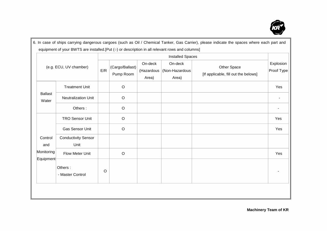
Machinery Team of KR
6. In case of ships carrying dangerous cargoes (such as Oil / Chemical Tanker, Gas Carrier), please indicate the spaces where each part and
equipment of your BWTS are installed.[Put (○) or description in all relevant rows and columns]
Installed Spaces
(e.g. ECU, UV chamber) E/R
(Cargo/Ballast)
Pump Room
On-deck
(Hazardous
Area)
On-deck
(Non-Hazardous
Area)
Other Space
[If applicable, fill out the belows]
Explosion
Proof Type
Treatment Unit O Yes
Neutralization Unit O - Ballast
Water
Others : O -
TRO Sensor Unit O Yes
Gas Sensor Unit O Yes
Conductivity Sensor
Unit
Flow Meter Unit O Yes
Control
and
Monitoring
Equipment
Others :
- Master Control O -

Machinery Team of KR
7. In case where the BWTS is installed on board Oil/Chemical Tankers and if it is equipped with
monitoring devices which take samples from ballast pipe lines, please answer the following questions.
No. Question Answer
1 What sampling type of monitoring equipment is used?
□ N/A ■ TRO Sensor Unit □ Gas Sensor Unit □ Others : Dissolved Oxygen Monitoring
2 Is the monitoring equipment an explosion-proof type?
■ Yes □ No (I.S. Type)
3 Where is the monitoring equipment installed?
□ E/R ■ (Ballast or Cargo)Pump Room □ Others :
4
If the monitoring equipment of sampling type is installed in safety areas (e.g. E/R, Dedicated space) outside the cargo dangerous area, what kind of safety measures is taken against the risk of toxic or flammable gas?
■ Mechanical Ventilation ■ Gas Detection & Alarm □ Self-closing Gas-tight Door ■ Others : N/A
7-1. In the above case and where components are directly fitted in ballast pipe line, please
answer the following questions.
No. Question Answer Explosion
Proof Type □ N/A
■ TRO Sensor Unit ■ Yes □ No
□ Gas Sensor Unit □ Yes □ No
■ Flow Meter Unit ■ Yes □ No
□ Level Sensor Unit □ Yes □ No
□ Temp. Sensor Unit □ Yes □ No
■ Pressure Sensor Unit □ Yes □ No
□ Other 1 : Dissolved Oxygen Sensor □ Yes □ No
1 What components are directly fitted in ballast pipe line?
□ Other 2 :
□ Yes □ No
2
If the components are not of an explosion-proof type, what kind of safety measures is taken against the expected hazard?
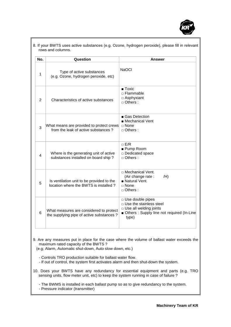
Machinery Team of KR
8. If your BWTS uses active substances (e.g. Ozone, hydrogen peroxide), please fill in relevant
rows and columns.
No. Question Answer
1 Type of active substances
(e.g. Ozone, hydrogen peroxide, etc)
NaOCl
2 Characteristics of active substances
■ Toxic □ Flammable □ Asphyxiant □ Others :
3 What means are provided to protect crews
from the leak of active substances ?
■ Gas Detection ■ Mechanical Vent □ None □ Others :
4 Where is the generating unit of active substances installed on board ship ?
□ E/R ■ Pump Room □ Dedicated space □ Others :
5 Is ventilation unit to be provided to the location where the BWTS is installed ?
□ Mechanical Vent. (Air change rate : /H) ■ Natural Vent. □ None □ Others :
6 What measures are considered to protect the supplying pipe of active substances ?
□ Use double pipes □ Use the stainless steel □ Use all welding joints ■ Others : Supply line not required (In-Line
type)
9. Are any measures put in place for the case where the volume of ballast water exceeds the
maximum rated capacity of the BWTS ? (e.g; Alarm, Automatic shut-down, Auto slow down, etc.) - Controls TRO production suitable for ballast water flow. - If out of control, the system first activates alarm and then shut-down the system. 10. Does your BWTS have any redundancy for essential equipment and parts (e.g. TRO
sensing units, flow meter unit, etc) to keep the system running in case of failure ?
- The BWMS is installed in each ballast pump so as to give redundancy to the system. - Pressure indicator (transmitter)

Machinery Team of KR
- Temperature indicator (transmitter), etc 11. Where are the spaces that you recommend to install sampling equipment according to BWM
Convention/Guideline G2 ? (e.g; Ballast Water Discharge Line, etc.) Ballast Water Discharge Line 12. Regarding the bi-products that are generated from the ballast water treatment process,
please fill in all relevant rows. No. Question Answer
1 Are dangerous gases generated as by-products after ballast water treatment process?
■ Yes □ No
2 What type of dangerous gases is generated? (e.g; Hydrogen, chlorine, etc.)
Hydrogen
3 What are properties of the by- product?
□ Toxic ■ Flammable □ Asphyxiant □ Others :
4
What is the generation rate of dangerous gases per each type of BWTS ? (e.g. 1m3/hr, etc) Please use a separate sheet if needed.
[0.7m3/hr of H2 treats 200on/hr of ballast water] 1,000 ton/hr – 3.5m3/hr 2,000 ton/hr – 7.5m3/hr 3,000 ton/hr – 10.5m3/hr
5 Is the gas detection unit an explosion-proof type? ■ Yes □ No
6
Where are the residue gases ventilated to after gas detection? (e.g. installation location of the gas detection unit, or safety area on the exposed weather deck)
Safe area on upper deck
Machinery Team of KR
Korean Register of Shipping, with the objective of GLOBAL TOP+, will always do our best
to provide the costumers with quicker and better quality services.
As the implementation of the Ballast Water Management Convention is imminent,
consideration is being given to the ship's design changes in relation to the installation of
Ballast Water Treatment System (hereinafter referred to as 'BWTS'), which is now put in
place on board some new ships.
The Machinery Team of this Society is planning to publish a Guidance for Installation of the
BWTS.
The KR's BWTS Guidance is intended to assist shipyards and ship owners in selecting
appropriate BWTS by describing the physical and mechanical properties of the BWTS,
technical aspects to be considered at the time of installation, and specific considerations
per each ship type.
In order for us to be able to complete the BWTS Guidance, we would highly appreciate it if
you could fill the questionnaire in as much as possible, and submit to us the completed
questionnaire by 31 March 2010 at the latest.
Your responses to the questionnaire are required for guidance purposes only and will not
be disclosed partly or wholly if specifically requested by the respondents.
Oh Joo-won / General Manager of Machinery Team
Korean Register of Shipping
Please return completed questionnaire to ; Fax : +82 42-862-6016 Email : [email protected] (Contact : Jee Jae-hoon, +82-42-869-9474)
Questionnaire about
Ballast Water Treatment System
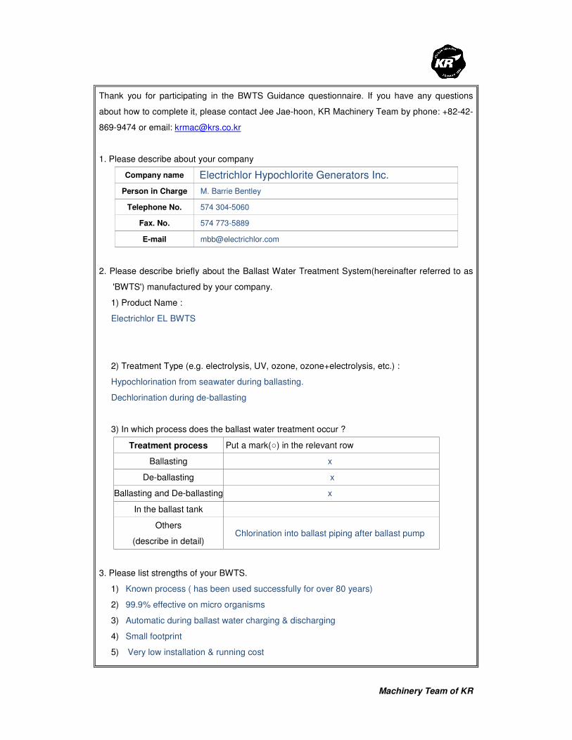
Machinery Team of KR
Thank you for participating in the BWTS Guidance questionnaire. If you have any questions
about how to complete it, please contact Jee Jae-hoon, KR Machinery Team by phone: +82-42-
869-9474 or email: [email protected]
1. Please describe about your company
Company name Electrichlor Hypochlorite Generators Inc.
Person in Charge M. Barrie Bentley
Telephone No. 574 304-5060
Fax. No. 574 773-5889
E-mail [email protected]
2. Please describe briefly about the Ballast Water Treatment System(hereinafter referred to as
'BWTS') manufactured by your company.
1) Product Name :
Electrichlor EL BWTS
2) Treatment Type (e.g. electrolysis, UV, ozone, ozone+electrolysis, etc.) :
Hypochlorination from seawater during ballasting.
Dechlorination during de-ballasting
3) In which process does the ballast water treatment occur ?
Treatment process Put a mark(○) in the relevant row
Ballasting x
De-ballasting x
Ballasting and De-ballasting x
In the ballast tank
Others
(describe in detail) Chlorination into ballast piping after ballast pump
3. Please list strengths of your BWTS.
1) Known process ( has been used successfully for over 80 years)
2) 99.9% effective on micro organisms
3) Automatic during ballast water charging & discharging
4) Small footprint
5) Very low installation & running cost

Machinery Team of KR
4. Please describe what needs to be specially considered when your BWTS is installed on
board ships.
1) Small piping installation from sea chest to unit and into upstream of ballast pump piping
2) Whether to install on deck on in machinery space
3) Hydrogen discharge to be piped upwards to atmosphere
5. Please fill in all applicable columns of the following table about the power consumption and
the required space.
Treatment Capacity
(m3/h)
Power Consumption (kW) Required Space (L x B x H)m
100 .45
200 .9
300 1.35
400 1.8
500 2.25
600 2.7
700 11.25
800 3.6
900 4.05
1000 4.5
1500 6.75
2000 9
2500 11.25
3000 13.5
3500 15.75
4000 18
4500 20.25
5000 22.5
6000 27
7000 31.5
Others :

Machinery Team of KR
6. In case of ships carrying dangerous cargoes (such as Oil / Chemical Tanker, Gas Carrier), please indicate the spaces where each part and
equipment of your BWTS are installed.[Put (○) or description in all relevant rows and columns]
(e.g. ECU, UV chamber)
Installed Spaces
Explosion Proof
Type E/R (Cargo/Ballast)
Pump Room
On-deck
(Hazardous
Area)
On-deck
(Non-Hazardous
Area)
Other Space
[If applicable, fill out the belows]
Ballast
Water
Treatment
Equipment
Treatment Unit x x x Class1, Div 2 Groups C&D
Neutralization Unit x x x
Others :
Control
and
Monitoring
Equipment
TRO Sensor Unit
Gas Sensor Unit
Flow Meter Unit x
Others :

Machinery Team of KR
7. In case where the BWTS is installed on board Oil/Chemical Tankers and if it is equipped with
monitoring devices which take samples from ballast pipe lines, please answer the following questions.
No. Question Answer
1 What sampling type of monitoring equipment is used?
□ N/A □ TRO Sensor Unit □ Gas Sensor Unit □ Others : Total Chlorine Analyzer
2 Is the monitoring equipment an explosion-proof type?
Yes □ No
3 Where is the monitoring equipment installed?
□ E/R □ (Ballast or Cargo)Pump Room □ Others : At the ballast water discharge
point
4
If the monitoring equipment of sampling type is installed in safety areas (e.g. E/R, Dedicated space) outside the cargo dangerous area, what kind of safety measures is taken against the risk of toxic or flammable gas?
□ Mechanical Ventilation □ Gas Detection & Alarm □ Self-closing Gas-tight Door □ Others :
7-1. In the above case and where components are directly fitted in ballast pipe line, please answer the following questions.
No. Question Answer Explosion
Proof Type
1 What components are directly fitted in ballast pipe line?
□ N/A
□ TRO Sensor Unit □ Yes □ No
□ Gas Sensor Unit □ Yes □ No
□ Flow Meter Unit □ Yes □ No
□ Level Sensor Unit □ Yes □ No
□ Temp. Sensor Unit □ Yes □ No
□ Pressure Sensor Unit □ Yes □ No
□ Other 1 :
□ Yes □ No
□ Other 2 :
□ Yes □ No
2
If the components are not of an explosion-proof type, what kind of safety measures is taken against the expected hazard?

Machinery Team of KR
8. If your BWTS uses active substances (e.g. Ozone, hydrogen peroxide), please fill in relevant
rows and columns.
No. Question Answer
1 Type of active substances
(e.g. Ozone, hydrogen peroxide, etc)
(Please describe briefly) Sodium Hypochlorite
2 Characteristics of active substances
□ Toxic NO □ Flammable NO □ Asphyxiant NO □ Others :
3 What means are provided to protect crews
from the leak of active substances ?
□ Gas Detection □ Mechanical Vent □ None □ Others : There is a drip tray that directs
any leaks to drain
4 Where is the generating unit of active substances installed on board ship ?
□ E/R □ Pump Room □ Dedicated space □ Others : Can be installed anywhere
5 Is ventilation unit to be provided to the location where the BWTS is installed ?
□ Mechanical Vent. (Air change rate : 800m
3/H)
□ Natural Vent. □ None □ Others :
6 What measures are considered to protect
the supplying pipe of active substances ?
□ Use double pipes □ Use the stainless steel □ Use all welding joints □ Others : PVC Lined Steel Pipe
9. Are any measures put in place for the case where the volume of ballast water exceeds the
maximum rated capacity of the BWTS ? (e.g; Alarm, Automatic shut-down, Auto slow down, etc.) No the unit is sized for the maximum ballast water flow rate 10. Does your BWTS have any redundancy for essential equipment and parts (e.g. TRO
sensing units, flow meter unit, etc) to keep the system running in case of failure ? Redundant dosing pumps and blowers
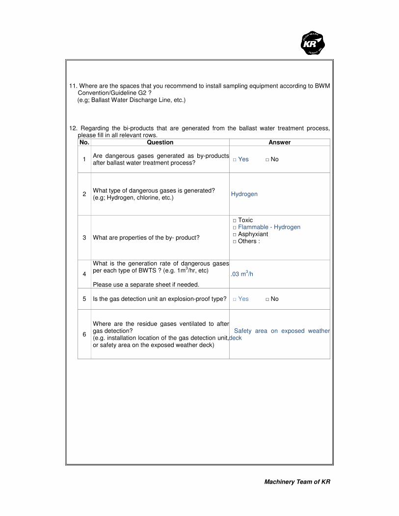
Machinery Team of KR
11. Where are the spaces that you recommend to install sampling equipment according to BWM
Convention/Guideline G2 ? (e.g; Ballast Water Discharge Line, etc.) 12. Regarding the bi-products that are generated from the ballast water treatment process,
please fill in all relevant rows. No. Question Answer
1 Are dangerous gases generated as by-products after ballast water treatment process?
□ Yes □ No
2 What type of dangerous gases is generated? (e.g; Hydrogen, chlorine, etc.)
Hydrogen
3 What are properties of the by- product?
□ Toxic □ Flammable - Hydrogen □ Asphyxiant □ Others :
4
What is the generation rate of dangerous gases per each type of BWTS ? (e.g. 1m
3/hr, etc)
Please use a separate sheet if needed.
.03 m
3/h
5 Is the gas detection unit an explosion-proof type? □ Yes □ No
6
Where are the residue gases ventilated to after gas detection? (e.g. installation location of the gas detection unit, or safety area on the exposed weather deck)
Safety area on exposed weather deck

Machinery Team of KR
Korean Register of Shipping, with the objective of GLOBAL TOP+, will always do our best
to provide the costumers with quicker and better quality services.
As the implementation of the Ballast Water Management Convention is imminent,
consideration is being given to the ship's design changes in relation to the installation of
Ballast Water Treatment System (hereinafter referred to as 'BWTS'), which is now put in
place on board some new ships.
The Machinery Team of this Society is planning to publish a Guidance for Installation of the
BWTS.
The KR's BWTS Guidance is intended to assist shipyards and ship owners in selecting
appropriate BWTS by describing the physical and mechanical properties of the BWTS,
technical aspects to be considered at the time of installation, and specific considerations
per each ship type.
In order for us to be able to complete the BWTS Guidance, we would highly appreciate it if
you could fill the questionnaire in as much as possible, and submit to us the completed
questionnaire by 31 March 2010 at the latest.
Your responses to the questionnaire are required for guidance purposes only and will not
be disclosed partly or wholly if specifically requested by the respondents.
Oh Joo-won / General Manager of Machinery Team
Korean Register of Shipping
Please return completed questionnaire to ; Fax : +82 42-862-6016 Email : [email protected] (Contact : Jee Jae-hoon, +82-42-869-9474)
Questionnaire about
Ballast Water Treatment System

Machinery Team of KR
Thank you for participating in the BWTS Guidance questionnaire. If you have any questions
about how to complete it, please contact Jee Jae-hoon, KR Machinery Team by phone: +82-42-
869-9474 or email: [email protected]
1. Please describe about your company
Company name Severn Trent De Nora
Person in Charge William Burroughs
Telephone No. +1 281 274 8472
Fax. No. +1 281 240 6762
E-mail [email protected]
2. Please describe briefly about the Ballast Water Treatment System (hereinafter referred to as
'BWTS') manufactured by your company.
1) Product Name : BalPure®
2) Treatment Type (e.g. electrolysis, UV, ozone, ozone+electrolysis, etc.) :
UPTAKE: 40µm pre-filtration + electrolysis (NaHOCl)
DISCHARGE: TRO neutralization
3) In which process does the ballast water treatment occur ?
Treatment process Put a mark(○) in the relevant row
Ballasting ○
De-ballasting Neutralization only – Sodium Bisulfite
Ballasting and De-ballasting
In the ballast tank Optional – to prevent reqrowth/can circulate & redoes
in the ballast tanks.
Others
(describe in detail)
○
DISCHARGE – TRO Neutralization only
3. Please list strengths of your BWTS.
1) Meets current interim California performance standards & current MEPC D-2
2) Meets USCG Phase 1 & Phase 2 proposed standards
3) Will meet California Final performance standards (CY 2020)

Machinery Team of KR
4) Filtration provides improvement to sediment control (Regulation B-5). Also, provides
compliance with MEPC 150(55) Guidelines
5) Fully automated/integrated into ships’ ballast water control system. Instant on-
instantaneous production of sodium hypochlorite for disinfection of uptake ballast water.
Electronic compliance with Regulation B-2 & Appendix II, Form of Ballast Water Record
Book.
6) Very low maintenance – approximately 4 hours per month.
7) Specialized/revolutionary DSA® electrode coating allows full-power at reversed current –
totally eliminating any/all electrolyzer cleaning requirements. Automatic self-cleaning system.
8) Slip-stream bypass feed to electrolytic generator. BalPure® is installed in engine
room/machinery room – to avoid added capital expense for hazardous area costs. Can be
single-skid mounted or modularized for retrofit in spaces available.
4. Please describe what needs to be specially considered when your BWTS is installed on
board ships.
1) Filter can be provided as Atex/Hazardous location/Ex-Proof for hazardous cargo
applications when needed.
2) BalPure® system can be installed single skid or multiple/modularized for retrofit
applications
3) Requires salt water at > 10 psu. This can be taken from the harbor or carried in a small
ballast tank. Requirement is 1% of total ballast volume rate.
5. Please fill in all applicable columns of the following table about the power consumption and
the required space.
Treatment Capacity
(m3/h) Power Consumption (kW) Required Space (L x B x H)m
250 - 750 40 MAX
Discharge ~ 250 W 4.8 x 1.8 x 2.8
750 – 1150 72 MAX (uptake only)
Discharge ~ 250 W 4.8 x 1.8 x 2.8
1150 – 1550 104 MAX (uptake only)
Discharge ~ 250 W 4.8 x 1.8 x 2.8
1550 – 2500 189 MAX (uptake only)
Discharge ~ 500 W 6.2 x 2.0 x 3.2
2500 – 3500 231 MAX (uptake only)
Discharge ~ 500 W 6.6 x 2.0 x 3.2

Machinery Team of KR
3500 – 4500 275 MAX (uptake only)
Discharge ~ 750 W 6.6 x 2.0 x 3.2
4500 - 5800 343 MAX (uptake only)
Discharge ~ 750 W 6.6 x 2.0 x 3.2
6000 360 MAX (uptake only)
Discharge ~ 1 kW 6.6 x 2.0 x 3.2
7000 420 MAX (uptake only)
Discharge ~ 1.25 kW 6.6 x 2.5 x 3.2
8000 480 MAX (uptake only)
Discharge ~ 1.50 kW 6.6 x 2.5 x 3.2
9000 540 MAX (uptake only)
Discharge ~ 1.75 kW 7.0 x 3.0 x 3.2
Others :
Each specified size is
optimized with DC power
source (transformer/SCR-
based rectifier) & specialized
electrolytic cells.

Machinery Team of KR
6. In case of ships carrying dangerous cargoes (such as Oil / Chemical Tanker, Gas Carrier), please indicate the spaces where each part and
equipment of your BWTS are installed.[Put (○) or description in all relevant rows and columns]
Installed Spaces
(e.g. ECU, UV chamber) E/R
(Cargo/Ballast)
Pump Room
On-deck
(Hazardous
Area)
On-deck
(Non-Hazardous
Area)
Other Space
[If applicable, fill out the belows]
Explosion
Proof Type
Treatment Unit ○ ○ ○ ○ Reduced Capex when installed in E/R ○
Neutralization Unit ○ ○ ○ ○ Reduced Capex when installed in E/R ○ Ballast
Water
Treatment
Equipment
Others :
TRO Sensor Unit ○ ○ ○
Gas Sensor Unit ○ ○ ○ ○ Hydrogen gas detector ○
Flow Meter Unit ○ ○ ○ ○ ○
Control
and
Monitoring
Equipment Others :

Machinery Team of KR
7. In case where the BWTS is installed on board Oil/Chemical Tankers and if it is equipped with
monitoring devices which take samples from ballast pipe lines, please answer the following questions.
No. Question Answer
1 What sampling type of monitoring equipment is used?
□ N/A X TRO Sensor Unit X Gas Sensor Unit (hydrogen) □ Others :
2 Is the monitoring equipment an explosion-proof type?
X Yes □ No
3 Where is the monitoring equipment installed?
X E/R X (Ballast or Cargo)Pump Room □ Others :
4
If the monitoring equipment of sampling type is installed in safety areas (e.g. E/R, Dedicated space) outside the cargo dangerous area, what kind of safety measures is taken against the risk of toxic or flammable gas?
X Mechanical Ventilation X Gas Detection & Alarm □ Self-closing Gas-tight Door □ Others : Hydrogen byproduct is diluted to less than
1% H2 in air & vented to safe location. H2 detector is adjacent to equipment
7-1. In the above case and where components are directly fitted in ballast pipe line,
please answer the following questions.
No. Question Answer Explosion
Proof Type
□ N/A
X TRO Sensor Unit X Yes □ No
□ Gas Sensor Unit □ Yes □ No
Flow Meter Unit Yes □ No
□ Level Sensor Unit □ Yes □ No
□ Temp. Sensor Unit □ Yes □ No
□ Pressure Sensor Unit □ Yes □ No
X Other 1 : ORP bisulfite
X Yes □ No
1
What components are directly fitted in ballast pipe line? Flow meter is outside the ballast line; no penetration needed
□ Other 2 :
□ Yes □ No
2
If the components are not of an explosion-proof type, what kind of safety measures is taken against the expected hazard?
Electronics are intrinsically safe
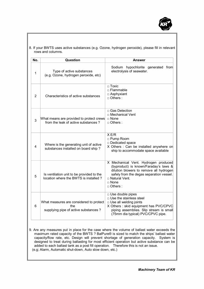
Machinery Team of KR
8. If your BWTS uses active substances (e.g. Ozone, hydrogen peroxide), please fill in relevant
rows and columns.
No. Question Answer
1 Type of active substances
(e.g. Ozone, hydrogen peroxide, etc)
Sodium hypochlorite generated from electrolysis of seawater.
2 Characteristics of active substances
□ Toxic □ Flammable □ Asphyxiant □ Others :
3 What means are provided to protect crews
from the leak of active substances ?
□ Gas Detection □ Mechanical Vent □ None □ Others :
4 Where is the generating unit of active substances installed on board ship ?
X E/R □ Pump Room □ Dedicated space X Others : Can be installed anywhere on
ship to accommodate space available
5 Is ventilation unit to be provided to the location where the BWTS is installed ?
X Mechanical Vent. Hydrogen produced (byproduct) is known/Faraday’s laws & dilution blowers to remove all hydrogen safely from the degas separation vessel.
□ Natural Vent. □ None □ Others :
6 What measures are considered to protect
the supplying pipe of active substances ?
□ Use double pipes □ Use the stainless steel □ Use all welding joints X Others : skid equipment has PVC/CPVC
piping assemblies. Slip stream is small (75mm dia typical) PVC/CPVC pipe.
9. Are any measures put in place for the case where the volume of ballast water exceeds the
maximum rated capacity of the BWTS ? BalPure® is sized to match the ships’ ballast water capacity/flow rate, etc. Design will prevent shortage of generation capacity. System is designed to treat during ballasting for most efficient operation but active substance can be added to each ballast tank as a post fill operation. Therefore this is not an issue.
(e.g; Alarm, Automatic shut-down, Auto slow down, etc.)
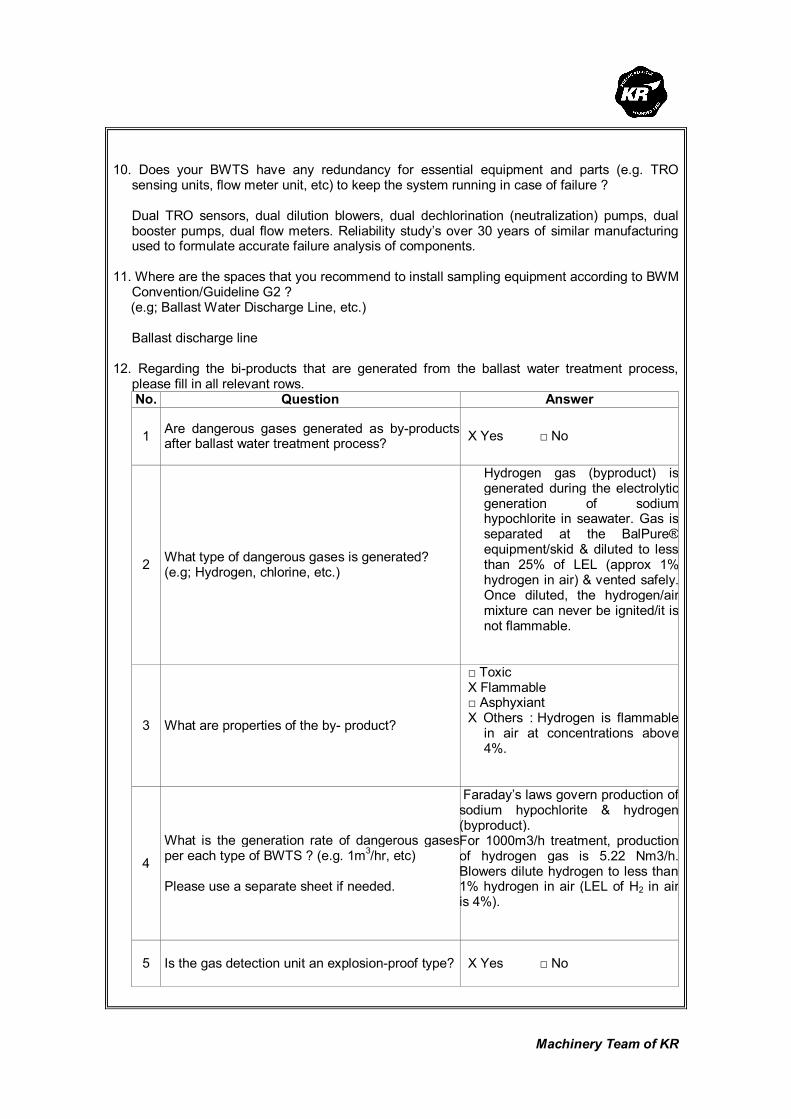
Machinery Team of KR
10. Does your BWTS have any redundancy for essential equipment and parts (e.g. TRO
sensing units, flow meter unit, etc) to keep the system running in case of failure ? Dual TRO sensors, dual dilution blowers, dual dechlorination (neutralization) pumps, dual
booster pumps, dual flow meters. Reliability study’s over 30 years of similar manufacturing used to formulate accurate failure analysis of components.
11. Where are the spaces that you recommend to install sampling equipment according to BWM
Convention/Guideline G2 ? (e.g; Ballast Water Discharge Line, etc.) Ballast discharge line 12. Regarding the bi-products that are generated from the ballast water treatment process,
please fill in all relevant rows. No. Question Answer
1 Are dangerous gases generated as by-products after ballast water treatment process?
X Yes □ No
2 What type of dangerous gases is generated? (e.g; Hydrogen, chlorine, etc.)
Hydrogen gas (byproduct) is generated during the electrolytic generation of sodium hypochlorite in seawater. Gas is separated at the BalPure® equipment/skid & diluted to less than 25% of LEL (approx 1% hydrogen in air) & vented safely. Once diluted, the hydrogen/air mixture can never be ignited/it is not flammable.
3 What are properties of the by- product?
□ Toxic X Flammable □ Asphyxiant X Others : Hydrogen is flammable
in air at concentrations above 4%.
4
What is the generation rate of dangerous gases per each type of BWTS ? (e.g. 1m
3/hr, etc)
Please use a separate sheet if needed.
Faraday’s laws govern production of sodium hypochlorite & hydrogen (byproduct). For 1000m3/h treatment, production of hydrogen gas is 5.22 Nm3/h. Blowers dilute hydrogen to less than 1% hydrogen in air (LEL of H2 in air is 4%).
5 Is the gas detection unit an explosion-proof type? X Yes □ No

Machinery Team of KR
6
Where are the residue gases ventilated to after gas detection? (e.g. installation location of the gas detection unit, or safety area on the exposed weather deck)
Gasses are wholly contained in the process. 2-phase (liquid/gas) is separated in degas vessel & hydrogen is directed to a vent duct. Dilution air is added & the entire hydrogen/air mixture is directed via a vent duct outside the engine room. Detection unit is installed adjacent to the hydrogen vent duct to detect any unintentional duct failure/piping breaks at the BalPure® unit.

Machinery Team of KR
Korean Register of Shipping, with the objective of GLOBAL TOP+, will always do our best
to provide the costumers with quicker and better quality services.
As the implementation of the Ballast Water Management Convention is imminent,
consideration is being given to the ship's design changes in relation to the installation of
Ballast Water Treatment System (hereinafter referred to as 'BWTS'), which is now put in
place on board some new ships.
The Machinery Team of this Society is planning to publish a Guidance for Installation of the
BWTS.
The KR's BWTS Guidance is intended to assist shipyards and ship owners in selecting
appropriate BWTS by describing the physical and mechanical properties of the BWTS,
technical aspects to be considered at the time of installation, and specific considerations
per each ship type.
In order for us to be able to complete the BWTS Guidance, we would highly appreciate it if
you could fill the questionnaire in as much as possible, and submit to us the completed
questionnaire by 31 March 2010 at the latest.
Your responses to the questionnaire are required for guidance purposes only and will not
be disclosed partly or wholly if specifically requested by the respondents.
Oh Joo-won / General Manager of Machinery Team
Korean Register of Shipping Please return completed questionnaire to ; Fax : +82 42-862-6016 Email : [email protected] (Contact : Jee Jae-hoon, +82-42-869-9474)
Questionnaire about
Ballast Water Treatment System

Machinery Team of KR
Thank you for participating in the BWTS Guidance questionnaire. If you have any questions
about how to complete it, please contact Jee Jae-hoon, KR Machinery Team by phone: +82-42-
869-9474 or email: [email protected]
1. Please describe about your company
Company name RWO GmbH, Marine Water Technology Person in Charge Mr Steffen Schlöricke
Telephone No. 0049-421-53705225
Fax. No. 0049-421-53705442
E-mail [email protected]
2. Please describe briefly about the Ballast Water Treatment System(hereinafter referred to as
'BWTS') manufactured by your company.
1) Product Name : CleanBallast®
2) Treatment Type (e.g. electrolysis, UV, ozone, ozone+electrolysis, etc.) :
Filtration plus advanced electrolysis Ectosys®
3) In which process does the ballast water treatment occur ?
Treatment process Put a mark(○) in the relevant row
Ballasting
De-ballasting
Ballasting and De-ballasting X
In the ballast tank
Others
(describe in detail)
3. Please list strengths of your BWTS.
1) High reduction of sediment loads
2) Low pressure loss
3) Low power consumption
4) No increase in corrosion or material damage
5)

Machinery Team of KR
4. Please describe what needs to be specially considered when your BWTS is installed on
board ships.
1)
2)
3)
5. Please fill in all applicable columns of the following table about the power consumption and
the required space.
Treatment Capacity
(m3/h) Power Consumption (kW) Required Space (L x B x H)m
100
200
300
400
500
Installed total power: 170 kW
Power consumption: 10 - 55
kW/h
3 Disc filters, each: ø=980;
depth=1080; height=1300
EctoSys, each: ø700;
height=1100
Electrical cabinet: width=1200;
height=2000; depth=700
Rectifier: width=600;
height=2000; depth=750
Flushing pump: ø600;
height=2200
All in mm indication
600
700
800
900
1000
1500
2000
2500
3000
3500
4000
Machinery Team of KR
4500
5000
6000
7000
Others :

Machinery Team of KR
6. In case of ships carrying dangerous cargoes (such as Oil / Chemical Tanker, Gas Carrier), please indicate the spaces where each part and
equipment of your BWTS are installed.[Put (○) or description in all relevant rows and columns]
Installed Spaces
(e.g. ECU, UV chamber) E/R
(Cargo/Ballast)
Pump Room
On-deck
(Hazardous
Area)
On-deck
(Non-Hazardous
Area)
Other Space
[If applicable, fill out the belows]
Explosion
Proof Type
Treatment Unit X In non hazardous area
Neutralization Unit X In non hazardous area Ballast
Water
Treatment
Equipment
Others :
X In non hazardous area
TRO Sensor Unit X In non hazardous area
Gas Sensor Unit X In non hazardous area
Flow Meter Unit X In non hazardous area
Control
and
Monitoring
Equipment Others :
X In non hazardous area

Machinery Team of KR
7. In case where the BWTS is installed on board Oil/Chemical Tankers and if it is equipped with
monitoring devices which take samples from ballast pipe lines, please answer the following questions.
No. Question Answer
1 What sampling type of monitoring equipment is used?
□ N/A X TRO Sensor Unit X Gas Sensor Unit X Others :algae monitor, salinity meter
2 Is the monitoring equipment an explosion-proof type? □ Yes X No
3 Where is the monitoring equipment installed?
X E/R □ (Ballast or Cargo)Pump Room X Others : at BWTS
4
If the monitoring equipment of sampling type is installed in safety areas (e.g. E/R, Dedicated space) outside the cargo dangerous area, what kind of safety measures is taken against the risk of toxic or flammable gas?
□ Mechanical Ventilation □ Gas Detection & Alarm □ Self-closing Gas-tight Door X Others : no safety measures are taken
7-1. In the above case and where components are directly fitted in ballast pipe line,
please answer the following questions. No. Question Answer Explosion
Proof Type □ N/A X TRO Sensor Unit □ Yes X No X Gas Sensor Unit □ Yes X No X Flow Meter Unit □ Yes X No □ Level Sensor Unit □ Yes X No □ Temp. Sensor Unit □ Yes X No X Pressure Sensor Unit □ Yes X No
X Other 1 : salinity meter
□ Yes X No
1 What components are directly fitted in ballast pipe line?
X Other 2 : algae monitor
□ Yes X No
2
If the components are not of an explosion-proof type, what kind of safety measures is taken against the expected hazard?
BWTS: current design is not suitable for hazardous area

Machinery Team of KR
8. If your BWTS uses active substances (e.g. Ozone, hydrogen peroxide), please fill in relevant
rows and columns.
No. Question Answer
1 Type of active substances (e.g. Ozone, hydrogen peroxide, etc)
Hydroxyl Radicals, OH* Hypochloric acid, HOCL Hypochlorite, OCL¯
2 Characteristics of active substances
□ Toxic □ Flammable □ Asphyxiant X Others : electrochemical oxidation
3 What means are provided to protect crews from the leak of active substances ?
□ Gas Detection □ Mechanical Vent □ None X Others : N/A
4 Where is the generating unit of active substances installed on board ship ?
X E/R □ Pump Room □ Dedicated space □ Others :
5 Is ventilation unit to be provided to the location where the BWTS is installed ?
□ Mechanical Vent. (Air change rate : /H) X Natural Vent. □ None □ Others :
6 What measures are considered to protect
the supplying pipe of active substances ?
□ Use double pipes □ Use the stainless steel □ Use all welding joints X Others : N/A
9. Are any measures put in place for the case where the volume of ballast water exceeds the
maximum rated capacity of the BWTS ? (e.g; Alarm, Automatic shut-down, Auto slow down, etc.) Alarm 10. Does your BWTS have any redundancy for essential equipment and parts (e.g. TRO
sensing units, flow meter unit, etc) to keep the system running in case of failure ? No redundancy in case of standard equipment

Machinery Team of KR
11. Where are the spaces that you recommend to install sampling equipment according to BWM
Convention/Guideline G2 ? (e.g; Ballast Water Discharge Line, etc.) There are any recommendation by manufacture. Installation of sampling equipment has to be installed acc. to G2. 12. Regarding the bi-products that are generated from the ballast water treatment process,
please fill in all relevant rows. No. Question Answer
1 Are dangerous gases generated as by-products after ballast water treatment process?
X Yes □ No
2 What type of dangerous gases is generated? (e.g; Hydrogen, chlorine, etc.)
HOBr, OBr¯, CHBr2CL
3 What are properties of the by- product?
□ Toxic □ Flammable □ Asphyxiant X Others : oxidation
4
What is the generation rate of dangerous gases per each type of BWTS ? (e.g. 1m3/hr, etc) Please use a separate sheet if needed.
Less than 2% H2 of the lower explosion limit (LEL)
5 Is the gas detection unit an explosion-proof type? □ Yes X No
6
Where are the residue gases ventilated to after gas detection? (e.g. installation location of the gas detection unit, or safety area on the exposed weather deck)
To open deck

Machinery Team of KR
Korean Register of Shipping, with the objective of GLOBAL TOP+, will always do our best
to provide the costumers with quicker and better quality services.
As the implementation of the Ballast Water Management Convention is imminent,
consideration is being given to the ship's design changes in relation to the installation of
Ballast Water Treatment System (hereinafter referred to as 'BWTS'), which is now put in
place on board some new ships.
The Machinery Team of this Society is planning to publish a Guidance for Installation of the
BWTS.
The KR's BWTS Guidance is intended to assist shipyards and ship owners in selecting
appropriate BWTS by describing the physical and mechanical properties of the BWTS,
technical aspects to be considered at the time of installation, and specific considerations
per each ship type.
In order for us to be able to complete the BWTS Guidance, we would highly appreciate it if
you could fill the questionnaire in as much as possible, and submit to us the completed
questionnaire by 31 March 2010 at the latest.
Your responses to the questionnaire are required for guidance purposes only and will not
be disclosed partly or wholly if specifically requested by the respondents.
Oh Joo-won / General Manager of Machinery Team
Korean Register of Shipping
Please return completed questionnaire to ; Fax : +82 42-862-6016 Email : [email protected] (Contact : Jee Jae-hoon, +82-42-869-9474)
Questionnaire about
Ballast Water Treatment System

Machinery Team of KR
Thank you for participating in the BWTS Guidance questionnaire. If you have any questions
about how to complete it, please contact Jee Jae-hoon, KR Machinery Team by phone: +82-42-
869-9474 or email: [email protected]
1. Please describe about your company
Company name MAHLE Industriefiltration GmbH
Person in Charge Ralph Michael
Telephone No. +49 (0)40 - 53 00 40-24110
Fax. No. +49 (0)40 - 53 00 40-24193
E-mail [email protected]
2. Please describe briefly about the Ballast Water Treatment System(hereinafter referred to as
'BWTS') manufactured by your company.
1) Product Name :
Ocean Protection System (OPS)
2) Treatment Type (e.g. electrolysis, UV, ozone, ozone+electrolysis, etc.) :
Filtration + UV (low-pressure lamps)
3) In which process does the ballast water treatment occur ?
Treatment process Put a mark(○) in the relevant row
Ballasting
De-ballasting
Ballasting and De-ballasting ○
In the ballast tank
Others
(describe in detail)
3. Please list strengths of your BWTS.
1) no chemicals, energy efficient UV disinfection
2) minimum operating cost, low power consumption
3) low pressure drop, can use already installed BW-pumps
4) system can be supplied as modular, skid mounted or installed in a container
5) no holding time in tanks necessary, no reaction nor chemical tanks

Machinery Team of KR
4. Please describe what needs to be specially considered when your BWTS is installed on
board ships.
1) nothing
2)
3)
5. Please fill in all applicable columns of the following table about the power consumption and
the required space.
Treatment Capacity
(m3/h) Power Consumption (kW)
Required Space (L x B x H)m
Variable construction (m3)
100
200 ~ 19 ~ 12
300 ~ 25 ~ 18
400
500 ~ 37 ~ 26
600 ~ 49 ~ 32
700 ~ 54 ~ 35
800 ~ 60 ~ 40
900
1000 ~ 77 ~ 49
1500 ~ 120 ~ 65
2000 ~ 159 ~ 93
2500
3000
3500
4000
4500
5000
6000
7000
Others :

Machinery Team of KR
6. In case of ships carrying dangerous cargoes (such as Oil / Chemical Tanker, Gas Carrier), please indicate the spaces where each part and
equipment of your BWTS are installed.[Put (○) or description in all relevant rows and columns]
Installed Spaces
(e.g. ECU, UV chamber) E/R
(Cargo/Ballast)
Pump Room
On-deck
(Hazardous
Area)
On-deck
(Non-Hazardous
Area)
Other Space
[If applicable, fill out the belows]
Explosion
Proof Type
Treatment Unit
Neutralization Unit Ballast
Water
Treatment
Equipment
Others :
TRO Sensor Unit
Gas Sensor Unit
Flow Meter Unit
Control
and
Monitoring
Equipment Others :

Machinery Team of KR
7. In case where the BWTS is installed on board Oil/Chemical Tankers and if it is equipped with
monitoring devices which take samples from ballast pipe lines, please answer the following questions.
No. Question Answer
1 What sampling type of monitoring equipment is used?
□ N/A □ TRO Sensor Unit □ Gas Sensor Unit □ Others :
2 Is the monitoring equipment an explosion-proof type?
□ Yes □ No
3 Where is the monitoring equipment installed?
□ E/R □ (Ballast or Cargo)Pump Room □ Others :
4
If the monitoring equipment of sampling type is installed in safety areas (e.g. E/R, Dedicated space) outside the cargo dangerous area, what kind of safety measures is taken against the risk of toxic or flammable gas?
□ Mechanical Ventilation □ Gas Detection & Alarm □ Self-closing Gas-tight Door □ Others :
7-1. In the above case and where components are directly fitted in ballast pipe line,
please answer the following questions.
No. Question Answer Explosion
Proof Type
□ N/A
□ TRO Sensor Unit □ Yes □ No
□ Gas Sensor Unit □ Yes □ No
□ Flow Meter Unit □ Yes □ No
□ Level Sensor Unit □ Yes □ No
□ Temp. Sensor Unit □ Yes □ No
□ Pressure Sensor Unit □ Yes □ No
□ Other 1 :
□ Yes □ No
1 What components are directly fitted in ballast pipe line?
□ Other 2 :
□ Yes □ No
2
If the components are not of an explosion-proof type, what kind of safety measures is taken against the expected hazard?
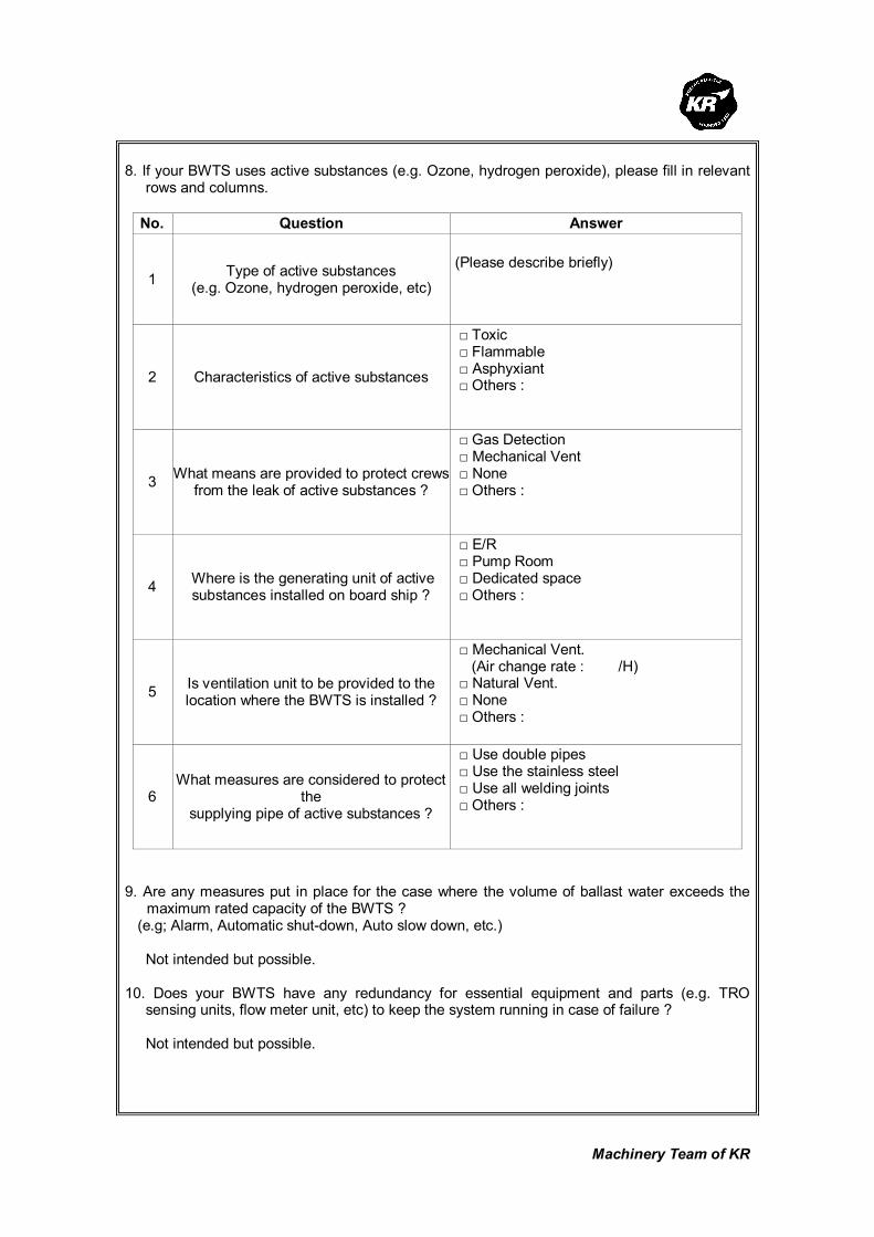
Machinery Team of KR
8. If your BWTS uses active substances (e.g. Ozone, hydrogen peroxide), please fill in relevant
rows and columns.
No. Question Answer
1 Type of active substances
(e.g. Ozone, hydrogen peroxide, etc)
(Please describe briefly)
2 Characteristics of active substances
□ Toxic □ Flammable □ Asphyxiant □ Others :
3 What means are provided to protect crews
from the leak of active substances ?
□ Gas Detection □ Mechanical Vent □ None □ Others :
4 Where is the generating unit of active substances installed on board ship ?
□ E/R □ Pump Room □ Dedicated space □ Others :
5 Is ventilation unit to be provided to the location where the BWTS is installed ?
□ Mechanical Vent. (Air change rate : /H) □ Natural Vent. □ None □ Others :
6 What measures are considered to protect
the supplying pipe of active substances ?
□ Use double pipes □ Use the stainless steel □ Use all welding joints □ Others :
9. Are any measures put in place for the case where the volume of ballast water exceeds the
maximum rated capacity of the BWTS ? (e.g; Alarm, Automatic shut-down, Auto slow down, etc.)
Not intended but possible. 10. Does your BWTS have any redundancy for essential equipment and parts (e.g. TRO
sensing units, flow meter unit, etc) to keep the system running in case of failure ?
Not intended but possible.
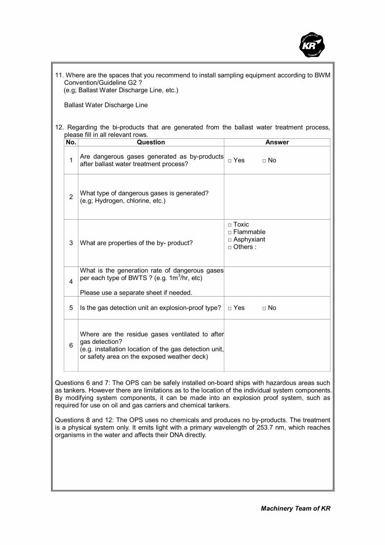
Machinery Team of KR
11. Where are the spaces that you recommend to install sampling equipment according to BWM
Convention/Guideline G2 ? (e.g; Ballast Water Discharge Line, etc.)
Ballast Water Discharge Line
12. Regarding the bi-products that are generated from the ballast water treatment process,
please fill in all relevant rows. No. Question Answer
1 Are dangerous gases generated as by-products after ballast water treatment process?
□ Yes □ No
2 What type of dangerous gases is generated? (e.g; Hydrogen, chlorine, etc.)
3 What are properties of the by- product?
□ Toxic □ Flammable □ Asphyxiant □ Others :
4
What is the generation rate of dangerous gases per each type of BWTS ? (e.g. 1m3/hr, etc) Please use a separate sheet if needed.
5 Is the gas detection unit an explosion-proof type? □ Yes □ No
6
Where are the residue gases ventilated to after gas detection? (e.g. installation location of the gas detection unit, or safety area on the exposed weather deck)
Questions 6 and 7: The OPS can be safely installed on-board ships with hazardous areas such as tankers. However there are limitations as to the location of the individual system components. By modifying system components, it can be made into an explosion proof system, such as required for use on oil and gas carriers and chemical tankers. Questions 8 and 12: The OPS uses no chemicals and produces no by-products. The treatment is a physical system only. It emits light with a primary wavelength of 253.7 nm, which reaches organisms in the water and affects their DNA directly.

Machinery Team of KR
Korean Register of Shipping, with the objective of GLOBAL TOP+, will always do our best
to provide the costumers with quicker and better quality services.
As the implementation of the Ballast Water Management Convention is imminent,
consideration is being given to the ship's design changes in relation to the installation of
Ballast Water Treatment System (hereinafter referred to as 'BWTS'), which is now put in
place on board some new ships.
The Machinery Team of this Society is planning to publish a Guidance for Installation of the
BWTS.
The KR's BWTS Guidance is intended to assist shipyards and ship owners in selecting
appropriate BWTS by describing the physical and mechanical properties of the BWTS,
technical aspects to be considered at the time of installation, and specific considerations
per each ship type.
In order for us to be able to complete the BWTS Guidance, we would highly appreciate it if
you could fill the questionnaire in as much as possible, and submit to us the completed
questionnaire by 31 March 2010 at the latest.
Your responses to the questionnaire are required for guidance purposes only and will not
be disclosed partly or wholly if specifically requested by the respondents.
Oh Joo-won / General Manager of Machinery Team
Korean Register of Shipping
Please return completed questionnaire to ; Fax : +82 42-862-6016 Email : [email protected] (Contact : Jee Jae-hoon, +82-42-869-9474)
Questionnaire about
Ballast Water Treatment System

Machinery Team of KR
Thank you for participating in the BWTS Guidance questionnaire. If you have any questions
about how to complete it, please contact Jee Jae-hoon, KR Machinery Team by phone: +82-42-
869-9474 or email: [email protected]
1. Please describe about your company
Company name Siemens Water Technologies
Person in Charge Louis Lombardo
Telephone No. +1 908 851 6930
Fax. No. + 1 908 851 6906
E-mail [email protected]
2. Please describe briefly about the Ballast Water Treatment System(hereinafter referred to as
'BWTS') manufactured by your company.
1) Product Name :
SiCURE™ Ballast Water Management System
2) Treatment Type (e.g. electrolysis, UV, ozone, ozone+electrolysis, etc.) :
Filtration and electrochlorination with proprietary control logic.
3) In which process does the ballast water treatment occur ?
Treatment process Put a mark(○) in the relevant row
Ballasting ○
De-ballasting
Ballasting and De-ballasting
In the ballast tank
Others
(describe in detail)
3. Please list strengths of your BWTS.
1) The production of active substance in a side stream generates several advantages as:
Low pressure drop, flexible footprint, easy to install
2) Treatment only on uptake of ballast water results in low operating expenses
3) No need of handling or storage of chemicals due to in-situ production of active substance,
no need for de-chlorination chemicals and self cleaning design (no cleaning chemicals)
4) Based on more than 35 years proven Chloropac technology guarantees for safety and
reliability

Machinery Team of KR
5) Dual Action option: The SiCURE System can be customized to be used for BWT while
ballasting and for Biofouling control of sea water pipelines for cooling water circuits during
voyage
4. Please describe what needs to be specially considered when your BWTS is installed on
board ships.
No special requirements
5. Please fill in all applicable columns of the following table about the power consumption and
the required space.
Treatment Capacity
(m3/h) Power Consumption (kW) Required Space (L x B x H)m
100 15 Flexible footprint ca. 9.5 m2
200 21 Flexible footprint ca. 9.5 m2
300 28 Flexible footprint ca. 9.5 m2
400 33.7 Flexible footprint ca. 9.5 m2
500 41 Flexible footprint ca. 10.1 m2
600 46 Flexible footprint ca. 10.1 m2
700 53 Flexible footprint ca. 10.1 m2
800 60 Flexible footprint ca. 10.1 m2
900 69 Flexible footprint ca. 10.1 m2
1000 73 Flexible footprint ca. 12.7 m2
1500 107 Flexible footprint ca. 15.2 m2
2000 145 Flexible footprint ca. 15.8 m2
2500 190 Flexible footprint ca. 15.8 m2
3000 216 Flexible footprint ca. 23.0 m2
3500 265 Flexible footprint ca. 23.0 m2
4000 292 Flexible footprint ca. 30.7 m2
4500 339 Flexible footprint ca. 30.7 m2
5000 368 Flexible footprint ca. 30.7 m2
6000 440 Flexible footprint ca. 42.8 m2
7000 513 Flexible footprint ca. 44.8 m2
Others :
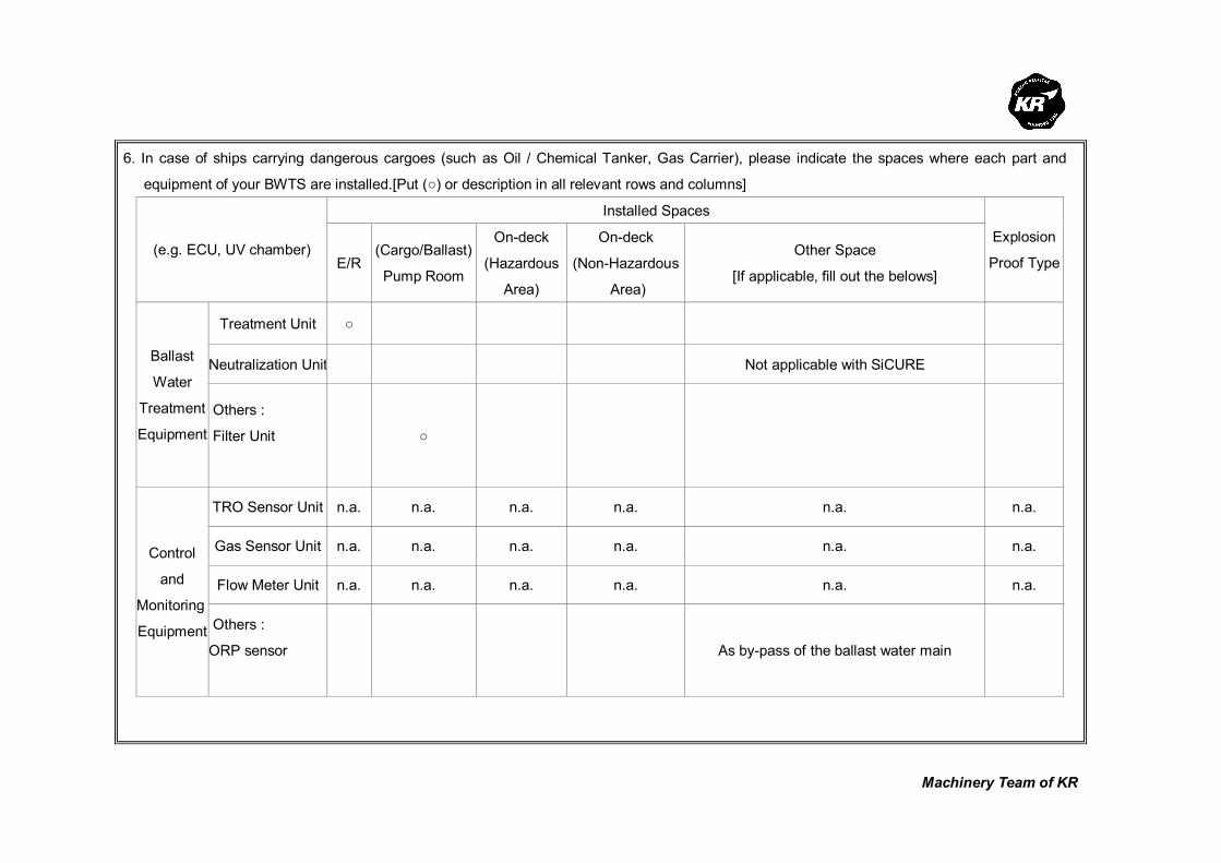
Machinery Team of KR
6. In case of ships carrying dangerous cargoes (such as Oil / Chemical Tanker, Gas Carrier), please indicate the spaces where each part and
equipment of your BWTS are installed.[Put (○) or description in all relevant rows and columns]
Installed Spaces
(e.g. ECU, UV chamber) E/R
(Cargo/Ballast)
Pump Room
On-deck
(Hazardous
Area)
On-deck
(Non-Hazardous
Area)
Other Space
[If applicable, fill out the belows]
Explosion
Proof Type
Treatment Unit ○
Neutralization Unit Not applicable with SiCURE Ballast
Water
Treatment
Equipment
Others :
Filter Unit
○
TRO Sensor Unit n.a. n.a. n.a. n.a. n.a. n.a.
Gas Sensor Unit n.a. n.a. n.a. n.a. n.a. n.a.
Flow Meter Unit n.a. n.a. n.a. n.a. n.a. n.a.
Control
and
Monitoring
Equipment Others :
ORP sensor
As by-pass of the ballast water main
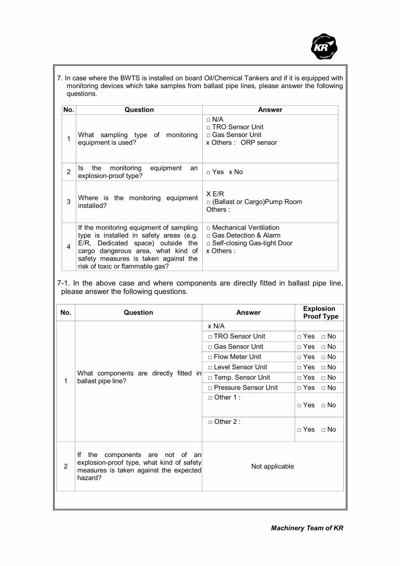
Machinery Team of KR
7. In case where the BWTS is installed on board Oil/Chemical Tankers and if it is equipped with
monitoring devices which take samples from ballast pipe lines, please answer the following questions.
No. Question Answer
1 What sampling type of monitoring equipment is used?
□ N/A □ TRO Sensor Unit □ Gas Sensor Unit x Others : ORP sensor
2 Is the monitoring equipment an explosion-proof type?
□ Yes x No
3 Where is the monitoring equipment installed?
X E/R □ (Ballast or Cargo)Pump Room Others :
4
If the monitoring equipment of sampling type is installed in safety areas (e.g. E/R, Dedicated space) outside the cargo dangerous area, what kind of safety measures is taken against the risk of toxic or flammable gas?
□ Mechanical Ventilation □ Gas Detection & Alarm □ Self-closing Gas-tight Door x Others :
7-1. In the above case and where components are directly fitted in ballast pipe line, please answer the following questions.
No. Question Answer Explosion
Proof Type
x N/A
□ TRO Sensor Unit □ Yes □ No
□ Gas Sensor Unit □ Yes □ No
□ Flow Meter Unit □ Yes □ No
□ Level Sensor Unit □ Yes □ No
□ Temp. Sensor Unit □ Yes □ No
□ Pressure Sensor Unit □ Yes □ No
□ Other 1 :
□ Yes □ No
1 What components are directly fitted in ballast pipe line?
□ Other 2 :
□ Yes □ No
2
If the components are not of an explosion-proof type, what kind of safety measures is taken against the expected hazard?
Not applicable

Machinery Team of KR
8. If your BWTS uses active substances (e.g. Ozone, hydrogen peroxide), please fill in relevant
rows and columns.
No. Question Answer
1 Type of active substances
(e.g. Ozone, hydrogen peroxide, etc)
hypochlorite
2 Characteristics of active substances
x Toxic □ Flammable □ Asphyxiant □ Others :
3 What means are provided to protect crews
from the leak of active substances ?
□ Gas Detection □ Mechanical Vent □ None x Others :
4 Where is the generating unit of active substances installed on board ship ?
x E/R □ Pump Room □ Dedicated space □ Others :
5 Is ventilation unit to be provided to the location where the BWTS is installed ?
□ Mechanical Vent. (Air change rate : /H) □ Natural Vent. □ None x Others : No special requirement
6 What measures are considered to protect
the supplying pipe of active substances ?
□ Use double pipes □ Use the stainless steel □ Use all welding joints x Others :
9. Are any measures put in place for the case where the volume of ballast water exceeds the
maximum rated capacity of the BWTS ? (e.g; Alarm, Automatic shut-down, Auto slow down, etc.) Not necessary with SiCURE design 10. Does your BWTS have any redundancy for essential equipment and parts (e.g. TRO
sensing units, flow meter unit, etc) to keep the system running in case of failure ? Redundancy can be provided if requested

Machinery Team of KR
11. Where are the spaces that you recommend to install sampling equipment according to BWM
Convention/Guideline G2 ? (e.g; Ballast Water Discharge Line, etc.) In the ballast water discharge line 12. Regarding the bi-products that are generated from the ballast water treatment process,
please fill in all relevant rows. No. Question Answer
1 Are dangerous gases generated as by-products after ballast water treatment process?
□ Yes x No
2 What type of dangerous gases is generated? (e.g; Hydrogen, chlorine, etc.)
Hydrogen is produced as a by-product when generating hypochlorite. Hydrogen is removed before the ballast water treatment process (Before introducing the hypochlorite into the ballast water main)
3 What are properties of the by- product?
□ Toxic x Flammable □ Asphyxiant □ Others :
4
What is the generation rate of dangerous gases per each type of BWTS ? (e.g. 1m3/hr, etc) Please use a separate sheet if needed.
0.3 Nm3 Hydrogen gas is produced per every 100 m3 treated ballast water
5 Is the gas detection unit an explosion-proof type? □ Yes □ No
6
Where are the residue gases ventilated to after gas detection? (e.g. installation location of the gas detection unit, or safety area on the exposed weather deck)
Hydrogen is degassed and diluted constantly during the process. No accumulation can occur. Gas detection not necessary.

Machinery Team of KR
Korean Register of Shipping, with the objective of GLOBAL TOP+, will always do our best
to provide the costumers with quicker and better quality services.
As the implementation of the Ballast Water Management Convention is imminent,
consideration is being given to the ship's design changes in relation to the installation of
Ballast Water Treatment System (hereinafter referred to as 'BWTS'), which is now put in
place on board some new ships.
The Machinery Team of this Society is planning to publish a Guidance for Installation of the
BWTS.
The KR's BWTS Guidance is intended to assist shipyards and ship owners in selecting
appropriate BWTS by describing the physical and mechanical properties of the BWTS,
technical aspects to be considered at the time of installation, and specific considerations
per each ship type.
In order for us to be able to complete the BWTS Guidance, we would highly appreciate it if
you could fill the questionnaire in as much as possible, and submit to us the completed
questionnaire by 31 March 2010 at the latest.
Your responses to the questionnaire are required for guidance purposes only and will not
be disclosed partly or wholly if specifically requested by the respondents.
Oh Joo-won / General Manager of Machinery Team
Korean Register of Shipping
Please return completed questionnaire to ; Fax : +82 42-862-6016 Email : [email protected] (Contact : Jee Jae-hoon, +82-42-869-9474)
Questionnaire about
Ballast Water Treatment System

Machinery Team of KR
Thank you for participating in the BWTS Guidance questionnaire. If you have any questions
about how to complete it, please contact Jee Jae-hoon, KR Machinery Team by phone: +82-42-
869-9474 or email: [email protected]
1. Please describe about your company
Company name OptiMarin AS
Person in Charge Pal Sanner
Telephone No. +47 51 11 45 33
Fax. No. +47 51 12 31 03
E-mail [email protected]
2. Please describe briefly about the Ballast Water Treatment System(hereinafter referred to as
'BWTS') manufactured by your company.
1) Product Name : OptiMarin Ballast Water Treatment System.
The patented OptiMarin Ballast System is based on solid separation (filter) as pre-t
reatment and high doses of UV irradiation for inactivation of marine organisms, viru
ses and bacteria, without affecting the normal operation of the ship. Ballast water is
treated both during ballasting and de-ballasting to ensure a dual effect.
The OptiMarin Ballast System can be fitted in new ships and retrofitted in older
ships. The MicroKill Medium Pressure UV can handle almost any flow when
multiple chambers are built into a manifold system. The components in the
OptiMarin system are flexible; the filter can be installed either horizontally or
vertically. The installation is normally in the pump room or engine room and in
close proximity to the ballast pumps. Being flexible in design, the various
components do not need to be side by side but can be installed wherever they will
fit.
2) Treatment Type (e.g. electrolysis, UV, ozone, ozone+electrolysis, etc.) :
One Filter plus UV lamps/chambers based on flow rate.
3) In which process does the ballast water treatment occur ?
Treatment process Put a mark(○) in the relevant row
Ballasting Filtering and UV
De-ballasting UV only
Ballasting and De-ballasting √ (filter & UV for ballast / UV for deballast)
In the ballast tank None

Machinery Team of KR
Others
(describe in detail) None
3. Please list strengths of your BWTS.
1) Environmentally friendly – chemical free (no chemicals stored or made)
2) Simple and flexible design – modular, pieces can be placed where they fit
3) Few movable parts – 1 filter with 1 movable part, lamps are cleaned by flow – no
moving parts
4) Highly effective (99.999% removal of zoo plankton, 99.99% of phytoplankton)
5) Exceeds IMO Reg D-2. Type approval certificate issued by DnV
6) Low need for maintenance
7) No extra noise
8) Low weight / small foot print
9) Relatively low cost.
The OptiMarin Ballast System has been tested successfully according to the INTERNATIONAL CONVENTION FOR THE CONTROL AND MANAGEMENT OF SHIPS’ BALLAST WATER AND SEDIMENTS, 2004, D2 standard by NIVA (Norwegian Institute for Water Research). Verified by DNV: Based on these results we have also received confirmation from the California State Land Commission that we meet their standard for best available technologies to be implemented starting 2010. We meet current New York state regulations and the proposed US Coast Guard Regulations.
4. Please describe what needs to be specially considered when your BWTS is installed on
board ships.
1) UV chambers must be installed horizontally
2) Service area for filter and UV chambers
3) Max distance between UV power cabinets and UV chambers should not exceed 25
meters. ( Pls contact Optimarin if longer distance is needed)
5. Please fill in all applicable columns of the following table about the power consumption and
the required space.
Please note that the system requires 1 x UV lamp/chamber for every 167m3/hr. Each uses
approximately 38kw of power. We added numbers in parenthesis in the first column which
represents the maximum flow an OptiMarin system can handle for the requested flow.
Treatment Capacity
(m3/h) Power Consumption (kW) Required Space (L x B x H)m
100 (167) 38 See attached table
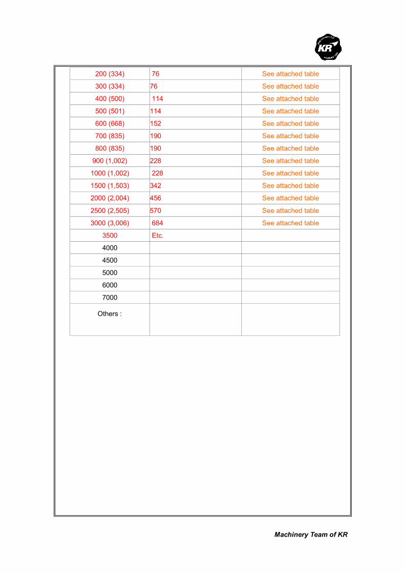
Machinery Team of KR
200 (334) 76 See attached table
300 (334) 76 See attached table
400 (500) 114 See attached table
500 (501) 114 See attached table
600 (668) 152 See attached table
700 (835) 190 See attached table
800 (835) 190 See attached table
900 (1,002) 228 See attached table
1000 (1,002) 228 See attached table
1500 (1,503) 342 See attached table
2000 (2,004) 456 See attached table
2500 (2,505) 570 See attached table
3000 (3,006) 684 See attached table
3500 Etc.
4000
4500
5000
6000
7000
Others :

Machinery Team of KR
6. In case of ships carrying dangerous cargoes (such as Oil / Chemical Tanker, Gas Carrier), please indicate the spaces where each part and
equipment of your BWTS are installed.[Put (○) or description in all relevant rows and columns]
We are currently not EX certified, but we are in the process of completing a feasibility study, and hope to have this completed by summer of 2010.
In the meantime, the filter is EX rated, so can be placed anywhere. The UV chambers and control/power system must be located in non-
hazardous areas.
Installed Spaces
(e.g. ECU, UV chamber) E/R
(Cargo/Ballast)
Pump Room
On-deck
(Hazardous
Area)
On-deck
(Non-Hazardous
Area)
Other Space
[If applicable, fill out the belows]
Explosion
Proof Type
Treatment Unit
Neutralization Unit Ballast
Water
Treatment
Equipment
Others :
TRO Sensor Unit
Gas Sensor Unit
Control
and
Monitoring
Equipment Flow Meter Unit

Machinery Team of KR
Others :

Machinery Team of KR
7. In case where the BWTS is installed on board Oil/Chemical Tankers and if it is equipped with
monitoring devices which take samples from ballast pipe lines, please answer the following questions.
See above. We do not have any ex certified equipment at the moment.
No. Question Answer
1 What sampling type of monitoring equipment is used?
□ N/A □ TRO Sensor Unit □ Gas Sensor Unit □ Others :
2 Is the monitoring equipment an explosion-proof type?
□ Yes □ No
3 Where is the monitoring equipment installed?
□ E/R □ (Ballast or Cargo)Pump Room □ Others
4
If the monitoring equipment of sampling type is installed in safety areas (e.g. E/R, Dedicated space) outside the cargo dangerous area, what kind of safety measures is taken against the risk of toxic or flammable gas?
□ Mechanical Ventilation □ Gas Detection & Alarm □ Self-closing Gas-tight Door □ Others :
7-1. In the above case and where components are directly fitted in ballast pipe line,
please answer the following questions.
No. Question Answer Explosion
Proof Type
□ N/A
□ TRO Sensor Unit □ Yes □ No
□ Gas Sensor Unit □ Yes □ No
□ Flow Meter Unit x Yes □ No
□ Level Sensor Unit □ Yes □ No
□ Temp. Sensor Unit x Yes □ No
□ Pressure Sensor Unit xYes □ No
□ Other 1 : UV intensity measurement
x□ Yes □ No
1 What components are directly fitted in ballast pipe line?
□ Other 2 :
□ Yes □ No
2
If the components are not of an explosion-proof type, what kind of safety measures is taken against the expected hazard?
Not Applicable

Machinery Team of KR
8. If your BWTS uses active substances (e.g. Ozone, hydrogen peroxide), please fill in relevant
rows and columns. We do not use any active substances, yet we exceed the IMO Ballast Water Standards from Reg D-2.
No. Question Answer
1 Type of active substances
(e.g. Ozone, hydrogen peroxide, etc)
None
2 Characteristics of active substances None
3 What means are provided to protect crews
from the leak of active substances ?
No substances, so no leakage
4 Where is the generating unit of active substances installed on board ship ?
No active substances
5 Is ventilation unit to be provided to the location where the BWTS is installed ?
No gases or chemicals, so no venting needed
6 What measures are considered to protect
the supplying pipe of active substances ?
No active substances.
9. Are any measures put in place for the case where the volume of ballast water exceeds the
maximum rated capacity of the BWTS ? (e.g; Alarm, Automatic shut-down, Auto slow down, etc.) Installed on all systems is a flow & pressure control valve (FPV). Should the limit be reached
this valve will restrict flow so as not to exceed the limit of the ballast water treatment system. 10. Does your BWTS have any redundancy for essential equipment and parts (e.g. TRO
sensing units, flow meter unit, etc) to keep the system running in case of failure ?
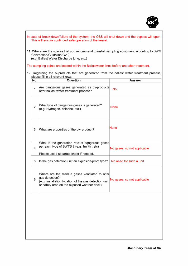
Machinery Team of KR
In case of break-down/failure of the system, the OBS will shut-down and the bypass will open.
This will ensure continued safe operation of the vessel. 11. Where are the spaces that you recommend to install sampling equipment according to BWM
Convention/Guideline G2 ? (e.g; Ballast Water Discharge Line, etc.) The sampling points are located within the Ballastwater lines before and after treatment. 12. Regarding the bi-products that are generated from the ballast water treatment process,
please fill in all relevant rows. No. Question Answer
1 Are dangerous gases generated as by-products after ballast water treatment process?
No
2 What type of dangerous gases is generated? (e.g; Hydrogen, chlorine, etc.)
None
3 What are properties of the by- product?
None
4
What is the generation rate of dangerous gases per each type of BWTS ? (e.g. 1m3/hr, etc) Please use a separate sheet if needed.
No gases, so not applicable
5 Is the gas detection unit an explosion-proof type? No need for such a unit
6
Where are the residue gases ventilated to after gas detection? (e.g. installation location of the gas detection unit, or safety area on the exposed weather deck)
No gases, so not applicable
Machinery Team of KR
Korean Register of Shipping, with the objective of GLOBAL TOP+, will always do our best
to provide the costumers with quicker and better quality services.
As the implementation of the Ballast Water Management Convention is imminent,
consideration is being given to the ship's design changes in relation to the installation of
Ballast Water Treatment System (hereinafter referred to as 'BWTS'), which is now put in
place on board some new ships.
The Machinery Team of this Society is planning to publish a Guidance for Installation of the
BWTS.
The KR's BWTS Guidance is intended to assist shipyards and ship owners in selecting
appropriate BWTS by describing the physical and mechanical properties of the BWTS,
technical aspects to be considered at the time of installation, and specific considerations
per each ship type.
In order for us to be able to complete the BWTS Guidance, we would highly appreciate it if
you could fill the questionnaire in as much as possible, and submit to us the completed
questionnaire by 31 March 2010 at the latest.
Your responses to the questionnaire are required for guidance purposes only and will not
be disclosed partly or wholly if specifically requested by the respondents.
Oh Joo-won / General Manager of Machinery Team
Korean Register of Shipping
Please return completed questionnaire to ; Fax : +82 42-862-6016 Email : [email protected] (Contact : Jee Jae-hoon, +82-42-869-9474)
Questionnaire about
Ballast Water Treatment System
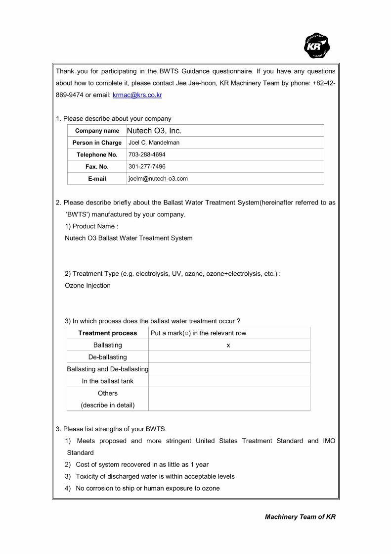
Machinery Team of KR
Thank you for participating in the BWTS Guidance questionnaire. If you have any questions
about how to complete it, please contact Jee Jae-hoon, KR Machinery Team by phone: +82-42-
869-9474 or email: [email protected]
1. Please describe about your company
Company name Nutech O3, Inc.
Person in Charge Joel C. Mandelman
Telephone No. 703-288-4694
Fax. No. 301-277-7496
E-mail [email protected]
2. Please describe briefly about the Ballast Water Treatment System(hereinafter referred to as
'BWTS') manufactured by your company.
1) Product Name :
Nutech O3 Ballast Water Treatment System
2) Treatment Type (e.g. electrolysis, UV, ozone, ozone+electrolysis, etc.) :
Ozone Injection
3) In which process does the ballast water treatment occur ?
Treatment process Put a mark(○) in the relevant row
Ballasting x
De-ballasting
Ballasting and De-ballasting
In the ballast tank
Others
(describe in detail)
3. Please list strengths of your BWTS.
1) Meets proposed and more stringent United States Treatment Standard and IMO
Standard
2) Cost of system recovered in as little as 1 year
3) Toxicity of discharged water is within acceptable levels
4) No corrosion to ship or human exposure to ozone

Machinery Team of KR
5) No toxic consumables are stored on ship
4. Please describe what needs to be specially considered when your BWTS is installed on
board ships.
1) Ballast loading rate/frequency of ballasting
2) Space Available in engine room for installation/can be modular installation
3) Layout of ballast tanks
optimal location of system will be determined after engineering survey
5. Please fill in all applicable columns of the following table about the power consumption and
the required space.
Treatment Capacity
(m3/h) Power Consumption (kW) Required Space (L x B x H)m
100
200 36.2 4.2 m2
300 36.5 4.2 m2
400
500
600 60.4 6.6 m2
700
800 68.4 9.1 m2
900
1000 86.9 9.1 m2
1500 123.2 10.6 m2
2000 148.4 14.5 m2
2500
3000 243.5 17.0 m2
3500
4000 317.6 20.3 m2
4500
5000 385.8 23.9 m2
6000 438.3 25.3 m2
7000
Others :
8000 613.8 36.8 m2

Machinery Team of KR
6. In case of ships carrying dangerous cargoes (such as Oil / Chemical Tanker, Gas Carrier), please indicate the spaces where each part and
equipment of your BWTS are installed.[Put (○) or description in all relevant rows and columns]
Installed Spaces
(e.g. ECU, UV chamber) E/R
(Cargo/Ballast)
Pump Room
On-deck
(Hazardous
Area)
On-deck
(Non-Hazardous
Area)
Other Space
[If applicable, fill out the belows]
Explosion
Proof Type
Treatment Unit x yes
Neutralization Unit x yes Ballast
Water
Treatment
Equipment
Ozone injector &
Pumps
x yes
TRO Sensor Unit x x yes
Gas Sensor Unit x x yes
Flow Meter Unit x x yes
Control
and
Monitoring
Equipment Others :
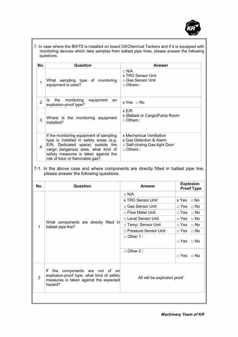
Machinery Team of KR
7. In case where the BWTS is installed on board Oil/Chemical Tankers and if it is equipped with
monitoring devices which take samples from ballast pipe lines, please answer the following questions.
No. Question Answer
1 What sampling type of monitoring equipment is used?
□ N/A x TRO Sensor Unit □ Gas Sensor Unit □ Others :
2 Is the monitoring equipment an explosion-proof type?
x Yes □ No
3 Where is the monitoring equipment installed?
x E/R x (Ballast or Cargo)Pump Room □ Others :
4
If the monitoring equipment of sampling type is installed in safety areas (e.g. E/R, Dedicated space) outside the cargo dangerous area, what kind of safety measures is taken against the risk of toxic or flammable gas?
x Mechanical Ventilation x Gas Detection & Alarm □ Self-closing Gas-tight Door □ Others :
7-1. In the above case and where components are directly fitted in ballast pipe line,
please answer the following questions.
No. Question Answer Explosion
Proof Type
□ N/A
x TRO Sensor Unit x Yes □ No
□ Gas Sensor Unit □ Yes □ No
□ Flow Meter Unit □ Yes □ No
□ Level Sensor Unit □ Yes □ No
□ Temp. Sensor Unit □ Yes □ No
□ Pressure Sensor Unit □ Yes □ No
□ Other 1 :
□ Yes □ No
1 What components are directly fitted in ballast pipe line?
□ Other 2 :
□ Yes □ No
2
If the components are not of an explosion-proof type, what kind of safety measures is taken against the expected hazard?
All will be explosion proof
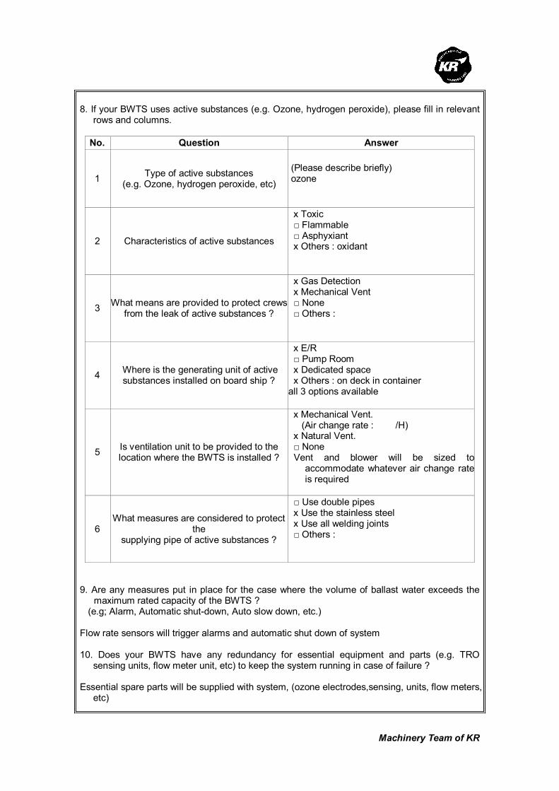
Machinery Team of KR
8. If your BWTS uses active substances (e.g. Ozone, hydrogen peroxide), please fill in relevant
rows and columns.
No. Question Answer
1 Type of active substances
(e.g. Ozone, hydrogen peroxide, etc)
(Please describe briefly) ozone
2 Characteristics of active substances
x Toxic □ Flammable □ Asphyxiant x Others : oxidant
3 What means are provided to protect crews
from the leak of active substances ?
x Gas Detection x Mechanical Vent □ None □ Others :
4 Where is the generating unit of active substances installed on board ship ?
x E/R □ Pump Room x Dedicated space x Others : on deck in container all 3 options available
5 Is ventilation unit to be provided to the location where the BWTS is installed ?
x Mechanical Vent. (Air change rate : /H) x Natural Vent. □ None Vent and blower will be sized to
accommodate whatever air change rate is required
6 What measures are considered to protect
the supplying pipe of active substances ?
□ Use double pipes x Use the stainless steel x Use all welding joints □ Others :
9. Are any measures put in place for the case where the volume of ballast water exceeds the
maximum rated capacity of the BWTS ? (e.g; Alarm, Automatic shut-down, Auto slow down, etc.) Flow rate sensors will trigger alarms and automatic shut down of system 10. Does your BWTS have any redundancy for essential equipment and parts (e.g. TRO
sensing units, flow meter unit, etc) to keep the system running in case of failure ? Essential spare parts will be supplied with system, (ozone electrodes,sensing, units, flow meters,
etc)

Machinery Team of KR
11. Where are the spaces that you recommend to install sampling equipment according to BWM
Convention/Guideline G2 ? (e.g; Ballast Water Discharge Line, etc.) Ballast water discharge line 12. Regarding the bi-products that are generated from the ballast water treatment process,
please fill in all relevant rows. No. Question Answer
1 Are dangerous gases generated as by-products after ballast water treatment process?
□ Yes x No
2 What type of dangerous gases is generated? (e.g; Hydrogen, chlorine, etc.)
N/A
3 What are properties of the by- product?
□ Toxic □ Flammable □ Asphyxiant □ Others :
4
What is the generation rate of dangerous gases per each type of BWTS ? (e.g. 1m3/hr, etc) Please use a separate sheet if needed.
N/A
5 Is the gas detection unit an explosion-proof type? x Yes □ No
6
Where are the residue gases ventilated to after gas detection? (e.g. installation location of the gas detection unit, or safety area on the exposed weather deck)
N/A

Machinery Team of KR
Korean Register of Shipping, with the objective of GLOBAL TOP+, will always do our best
to provide the costumers with quicker and better quality services.
As the implementation of the Ballast Water Management Convention is imminent,
consideration is being given to the ship's design changes in relation to the installation of
Ballast Water Treatment System (hereinafter referred to as 'BWTS'), which is now put in
place on board some new ships.
The Machinery Team of this Society is planning to publish a Guidance for Installation of the
BWTS.
The KR's BWTS Guidance is intended to assist shipyards and ship owners in selecting
appropriate BWTS by describing the physical and mechanical properties of the BWTS,
technical aspects to be considered at the time of installation, and specific considerations
per each ship type.
In order for us to be able to complete the BWTS Guidance, we would highly appreciate it if
you could fill the questionnaire in as much as possible, and submit to us the completed
questionnaire by 31 March 2010 at the latest.
Your responses to the questionnaire are required for guidance purposes only and will not
be disclosed partly or wholly if specifically requested by the respondents.
Oh Joo-won / General Manager of Machinery Team
Korean Register of Shipping
Please return completed questionnaire to ; Fax : +82 42-862-6016 Email : [email protected] (Contact : Jee Jae-hoon, +82-42-869-9474)
Questionnaire about
Ballast Water Treatment System

Machinery Team of KR
Thank you for participating in the BWTS Guidance questionnaire. If you have any questions
about how to complete it, please contact Jee Jae-hoon, KR Machinery Team by phone: +82-42-
869-9474 or email: [email protected]
1. Please describe about your company
Company name Alfa Laval
Person in Charge Per Warg, Business Manager
Telephone No. +46 8 530 654 33
Fax. No.
E-mail [email protected]
2. Please describe briefly about the Ballast Water Treatment System(hereinafter referred to as
'BWTS') manufactured by your company.
1) Product Name : PureBallast
2) Treatment Type (e.g. electrolysis, UV, ozone, ozone+electrolysis, etc.) : Advanced
Oxidation Technology
3) In which process does the ballast water treatment occur ?
Treatment process Put a mark(○) in the relevant row
Ballasting
De-ballasting
Ballasting and De-ballasting 0
In the ballast tank
Others
(describe in detail)
3. Please list strengths of your BWTS.
1) Free of chemicals
2) Modular design and small footprint, which means easy installation
3) Ballast & deballast as you do today
4) Experienced marine supplier with global sales and service network

Machinery Team of KR
4. Please describe what needs to be specially considered when your BWTS is installed on
board ships.
1) Space
2) Availability of power
3) Ballast pump pressure head
5. Please fill in all applicable columns of the following table about the power consumption and
the required space.
Treatment Capacity
(m3/h) Power Consumption (kW) Required Space (L x B x H)m
100
200
300
400
500 120 7
600
700
800
900
1000 240 12
1500 360 15
2000 480 20
2500 600 25
3000
3500
4000
4500
5000
6000
7000
Others :
250 60 4

Machinery Team of KR
6. In case of ships carrying dangerous cargoes (such as Oil / Chemical Tanker, Gas Carrier), please indicate the spaces where each part and
equipment of your BWTS are installed.[Put (○) or description in all relevant rows and columns]
Installed Spaces
(e.g. ECU, UV chamber) E/R
(Cargo/Ballast)
Pump Room
On-deck
(Hazardous
Area)
On-deck
(Non-Hazardous
Area)
Other Space
[If applicable, fill out the belows]
Explosion
Proof Type
Treatment Unit 0 0 0 0
Neutralization Unit na na Na na Ballast
Water
Treatment
Equipment
Others :
Filter
Cleaning-in-place
unit
0 0 0 0
TRO Sensor Unit
Gas Sensor Unit
Control
and
Monitoring
Equipment Flow Meter Unit 0 0 0 0

Machinery Team of KR
Others :
Control&
power distribution
0 0

Machinery Team of KR
7. In case where the BWTS is installed on board Oil/Chemical Tankers and if it is equipped with
monitoring devices which take samples from ballast pipe lines, please answer the following questions.
No. Question Answer
1 What sampling type of monitoring equipment is used?
X N/A □ TRO Sensor Unit □ Gas Sensor Unit □ Others :
2 Is the monitoring equipment an explosion-proof type?
□ Yes □ No
3 Where is the monitoring equipment installed?
□ E/R □ (Ballast or Cargo)Pump Room □ Others :
4
If the monitoring equipment of sampling type is installed in safety areas (e.g. E/R, Dedicated space) outside the cargo dangerous area, what kind of safety measures is taken against the risk of toxic or flammable gas?
□ Mechanical Ventilation □ Gas Detection & Alarm □ Self-closing Gas-tight Door □ Others :
7-1. In the above case and where components are directly fitted in ballast pipe line,
please answer the following questions.
No. Question Answer Explosion
Proof Type
□ N/A
□ TRO Sensor Unit □ Yes □ No
□ Gas Sensor Unit □ Yes □ No
X Flow Meter Unit X Yes □ No
X Level Sensor Unit X Yes □ No
X Temp. Sensor Unit X Yes □ No
X Pressure Sensor Unit X Yes □ No
□ Other 1 :
□ Yes □ No
1 What components are directly fitted in ballast pipe line?
□ Other 2 :
□ Yes □ No
2
If the components are not of an explosion-proof type, what kind of safety measures is taken against the expected hazard?

Machinery Team of KR
8. If your BWTS uses active substances (e.g. Ozone, hydrogen peroxide), please fill in relevant
rows and columns.
No. Question Answer
1 Type of active substances
(e.g. Ozone, hydrogen peroxide, etc)
(Please describe briefly)
2 Characteristics of active substances
□ Toxic □ Flammable □ Asphyxiant □ Others :
3 What means are provided to protect crews
from the leak of active substances ?
□ Gas Detection □ Mechanical Vent □ None □ Others :
4 Where is the generating unit of active substances installed on board ship ?
□ E/R □ Pump Room □ Dedicated space □ Others :
5 Is ventilation unit to be provided to the location where the BWTS is installed ?
□ Mechanical Vent. (Air change rate : /H) □ Natural Vent. □ None □ Others :
6 What measures are considered to protect
the supplying pipe of active substances ?
□ Use double pipes □ Use the stainless steel □ Use all welding joints □ Others :
9. Are any measures put in place for the case where the volume of ballast water exceeds the
maximum rated capacity of the BWTS ? (e.g; Alarm, Automatic shut-down, Auto slow down, etc.) Alarm 10. Does your BWTS have any redundancy for essential equipment and parts (e.g. TRO
sensing units, flow meter unit, etc) to keep the system running in case of failure ?

Machinery Team of KR
11. Where are the spaces that you recommend to install sampling equipment according to BWM
Convention/Guideline G2 ? (e.g; Ballast Water Discharge Line, etc.) PureBallast is equipped with sampling equipment. 12. Regarding the bi-products that are generated from the ballast water treatment process,
please fill in all relevant rows. No. Question Answer
1 Are dangerous gases generated as by-products after ballast water treatment process?
□ Yes X No
2 What type of dangerous gases is generated? (e.g; Hydrogen, chlorine, etc.)
3 What are properties of the by- product?
□ Toxic □ Flammable □ Asphyxiant □ Others :
4
What is the generation rate of dangerous gases per each type of BWTS ? (e.g. 1m3/hr, etc) Please use a separate sheet if needed.
5 Is the gas detection unit an explosion-proof type? □ Yes □ No
6
Where are the residue gases ventilated to after gas detection? (e.g. installation location of the gas detection unit, or safety area on the exposed weather deck)

Machinery Team of KR
Korean Register of Shipping, with the objective of GLOBAL TOP+, will always do our best
to provide the costumers with quicker and better quality services.
As the implementation of the Ballast Water Management Convention is imminent,
consideration is being given to the ship's design changes in relation to the installation of
Ballast Water Treatment System (hereinafter referred to as 'BWTS'), which is now put in
place on board some new ships.
The Machinery Team of this Society is planning to publish a Guidance for Installation of the
BWTS.
The KR's BWTS Guidance is intended to assist shipyards and ship owners in selecting
appropriate BWTS by describing the physical and mechanical properties of the BWTS,
technical aspects to be considered at the time of installation, and specific considerations
per each ship type.
In order for us to be able to complete the BWTS Guidance, we would highly appreciate it if
you could fill the questionnaire in as much as possible, and submit to us the completed
questionnaire by 30 April 2011 at the latest.
Your responses to the questionnaire are required for guidance purposes only and will not
be disclosed partly or wholly if specifically requested by the respondents.
Oh Joo-won / General Manager of Machinery Team
Korean Register of Shipping
Please return completed questionnaire to ; Fax : +82 42-862-6016 E-mail : [email protected] (Contact : Jang Jae-shik, +82-42-869-9456)
Questionnaire about
Ballast Water Treatment System

Machinery Team of KR
Thank you for participating in the BWTS Guidance questionnaire. If you have any questions
about how to complete it, please contact Jang Jae-shik, KR Machinery Team by phone: +82-42-
869-9456 or E-mail: [email protected]
1. Please describe about your company
Company name SunRui Marine Environment Engineering Company
Person in Charge Mr Yu Jiangshui
Telephone No. +86 (0)532-68725831
Fax. No. +86 (0)532-68725001
E-mail [email protected]
2. Please describe briefly about the Ballast Water Treatment System(hereinafter referred to as
'BWTS') manufactured by your company.
1) Product Name :
BalClorTM
2) Treatment Type (e.g. electrolysis, UV, ozone, ozone+electrolysis, etc.) :
Filtration + Electrolysis +Neutralization
3) In which process does the ballast water treatment occur ?
Treatment process Put a mark(○) in the relevant row
Ballasting ○ De-ballasting ○
Ballasting and De-ballasting
In the ballast tank
Others
(describe in detail)
3. Please list strengths of your BWTS.
1) side-stream
2) low power consumption
3) low maintenance cost
4) flexible modular design
5) function unaffected by water condition
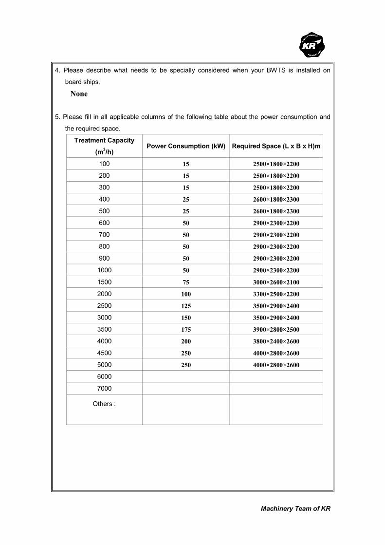
Machinery Team of KR
4. Please describe what needs to be specially considered when your BWTS is installed on
board ships.
None
5. Please fill in all applicable columns of the following table about the power consumption and
the required space.
Treatment Capacity
(m3/h)
Power Consumption (kW) Required Space (L x B x H)m
100 15 2500×1800×2200
200 15 2500×1800×2200
300 15 2500×1800×2200
400 25 2600×1800×2300
500 25 2600×1800×2300
600 50 2900×2300×2200
700 50 2900×2300×2200
800 50 2900×2300×2200
900 50 2900×2300×2200
1000 50 2900×2300×2200
1500 75 3000×2600×2100
2000 100 3300×2500×2200
2500 125 3500×2900×2400
3000 150 3500×2900×2400
3500 175 3900×2800×2500
4000 200 3800×2400×2600
4500 250 4000×2800×2600
5000 250 4000×2800×2600
6000
7000
Others :
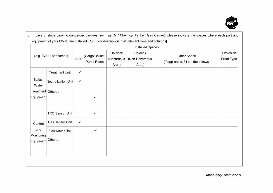
Machinery Team of KR
6. In case of ships carrying dangerous cargoes (such as Oil / Chemical Tanker, Gas Carrier), please indicate the spaces where each part and
equipment of your BWTS are installed.[Put (○) or description in all relevant rows and columns]
Installed Spaces
(e.g. ECU, UV chamber) E/R
(Cargo/Ballast)
Pump Room
On-deck
(Hazardous
Area)
On-deck
(Non-Hazardous
Area)
Other Space
[If applicable, fill out the belows]
Explosion
Proof Type
Treatment Unit
Neutralization Unit Ballast
Water
Treatment
Equipment
Others :
TRO Sensor Unit
Gas Sensor Unit
Flow Meter Unit
Control
and
Monitoring
Equipment Others :
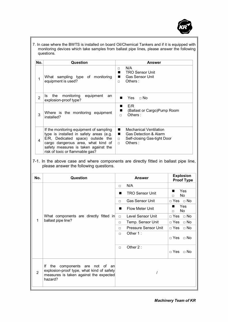
Machinery Team of KR
7. In case where the BWTS is installed on board Oil/Chemical Tankers and if it is equipped with
monitoring devices which take samples from ballast pipe lines, please answer the following questions.
No. Question Answer
1 What sampling type of monitoring equipment is used?
□ N/A TRO Sensor Unit Gas Sensor Unit
□ Others :
2 Is the monitoring equipment an explosion-proof type?
Yes □ No
3 Where is the monitoring equipment installed?
E/R (Ballast or Cargo)Pump Room
□ Others :
4
If the monitoring equipment of sampling type is installed in safety areas (e.g. E/R, Dedicated space) outside the cargo dangerous area, what kind of safety measures is taken against the risk of toxic or flammable gas?
Mechanical Ventilation Gas Detection & Alarm
□ Self-closing Gas-tight Door □ Others :
7-1. In the above case and where components are directly fitted in ballast pipe line,
please answer the following questions.
No. Question Answer Explosion
Proof Type
□ N/A
TRO Sensor Unit Yes □ No
□ Gas Sensor Unit □ Yes □ No
Flow Meter Unit Yes □ No
□ Level Sensor Unit □ Yes □ No
□ Temp. Sensor Unit □ Yes □ No
□ Pressure Sensor Unit □ Yes □ No
□ Other 1 :
□ Yes □ No
1 What components are directly fitted in ballast pipe line?
□ Other 2 :
□ Yes □ No
2
If the components are not of an explosion-proof type, what kind of safety measures is taken against the expected hazard?
/

Machinery Team of KR
8. If your BWTS uses active substances (e.g. Ozone, hydrogen peroxide), please fill in relevant rows and columns.
No. Question Answer
1 Type of active substances
(e.g. Ozone, hydrogen peroxide, etc)
(Please describe briefly)
2 Characteristics of active substances
□ Toxic □ Flammable □ Asphyxiant □ Others :
3 What means are provided to protect crews
from the leak of active substances ?
□ Gas Detection □ Mechanical Vent □ None □ Others :
4 Where is the generating unit of active substances installed on board ship ?
□ E/R □ Pump Room □ Dedicated space □ Others :
5 Is ventilation unit to be provided to the location where the BWTS is installed ?
□ Mechanical Vent. (Air change rate : /H) □ Natural Vent. □ None □ Others :
6 What measures are considered to protect
the supplying pipe of active substances ?
□ Use double pipes □ Use the stainless steel □ Use all welding joints □ Others :
9. Are any measures put in place for the case where the volume of ballast water exceeds the
maximum rated capacity of the BWTS ? (e.g; Alarm, Automatic shut-down, Auto slow down, etc.)
Alarm 10. Does your BWTS have any redundancy for essential equipment and parts (e.g. TRO
sensing units, flow meter unit, etc) to keep the system running in case of failure?
No

Machinery Team of KR
11. Where are the spaces that you recommend to install sampling equipment according to BWM Convention/Guideline G2 ?
(e.g; Ballast Water Discharge Line, etc.)
Near de-ballasting pipe outlet 12. Regarding the bi-products that are generated from the ballast water treatment process,
please fill in all relevant rows. No. Question Answer
1 Are dangerous gases generated as by-products after ballast water treatment process?
Yes □ No
2 What type of dangerous gases is generated? (e.g; Hydrogen, chlorine, etc.)
Hydrogen
3 What are properties of the by- product?
□ Toxic Flammable
□ Asphyxiant □ Others :
4
What is the generation rate of dangerous gases per each type of BWTS ? (e.g. 1m3/hr, etc) Please use a separate sheet if needed.
/
5 Is the gas detection unit an explosion-proof type? □ Yes No
6
Where are the residue gases ventilated to after gas detection? (e.g. installation location of the gas detection unit, or safety area on the exposed weather deck)
On Deck
Guideline for Application of BWTS in Ships Machinery Team
Guidelines for Application of Ballast Water
Treatment Systems in Ships
Issued date 30th Dec. 2010
Published by KOREAN REGISTER OF SHIPPING
90 Gajeongbukro, 23-7 Jang-dong Yuseong-gu
Daejeon, Republic of Korea
TEL : 042-869-9440
FAXZ : 042-862-6016
Website : http://www.krs.co.kr
※ In order to avoid any potential damage to Korea Register, dissemination, distribution or
copying of this document is prohibited without prior permission from the publishing division.
※ For any inquiries regarding this book, please contact
Jang, Jae-shik / Senior Surveyor (Email : [email protected], TEL : 042-869-9456, FAX : 042-862-6016)