Guide to Design of Structures for Robustness
150
CNR – Advisory Committee on Technical Recommendations for Construction CNR-DT 214 /2018 ROMA – CNR September 17, 2021 NATIONAL RESEARCH COUNCIL OF ITALY ADVISORY COMMITTEE ON TECHNICAL RECOMMENDATIONS FOR CONSTRUCTION Guide to Design of Structures for Robustness
Transcript of Guide to Design of Structures for Robustness

CNR – Advisory Committee on Technical Recommendations for Construction
CNR-DT 214 /2018
ROMA – CNR September 17, 2021
NATIONAL RESEARCH COUNCIL OF ITALY
ADVISORY COMMITTEE
ON TECHNICAL RECOMMENDATIONS FOR CONSTRUCTION
Guide to Design of Structures for Robustness

CNR – Advisory Committee on Technical Recommendations for Construction
CNR-DT 214 /2018
ROMA – CNR September 17, 2021
This document is subject to copyright
No part of this publication may be stored in a retrieval system, or
transmitted in any form or by any means
– electronic, mechanical, recording, or otherwise –
without the prior written permission
of the Italian National Research Council.
The reproduction of this document is permitted
for personal, noncommercial use.

CNR-DT 214 /2018
1
INDEX
1 INTRODUCTION ......................................................................................................................... 5
1.1 PREFACE .............................................................................................................................. 51.2 DEFINITIONS ....................................................................................................................... 8
2 RISK SCENARIOS AND QUANTIFICATION OF THE INTENSITY OF THE RELEVANT ACTION ................................................................................................................ 11
2.1 PREFACE ............................................................................................................................ 112.2 SEISMIC INDUCED PHENOMENA ................................................................................. 13
2.2.1 Earthquakes ...................................................................................................................... 132.2.2 Tsunamis ........................................................................................................................... 13
2.3 NATURAL GRAVITATIVE PHENOMENA .................................................................... 152.3.1 Debris slides ..................................................................................................................... 152.3.2 Debris flows ...................................................................................................................... 152.3.3 Rockfalls ........................................................................................................................... 162.3.4 Snow avalanches .............................................................................................................. 162.3.5 Volcanic eruptions ............................................................................................................ 17
2.4 FOUNDATION SETTLEMENTS ...................................................................................... 182.4.1 Subsidence ........................................................................................................................ 182.4.2 Water-table level variation ............................................................................................... 19
2.5 HYDRAULIC PHENOMENA ............................................................................................ 192.6 METEOROLOGICAL PHENOMENA .............................................................................. 20
2.6.1 Storms and tornadoes ....................................................................................................... 202.6.2 Ice formations ................................................................................................................... 21
2.7 FIRE AND DETONATION ................................................................................................ 212.7.1 Fire .................................................................................................................................... 212.7.2 Free-field explosions ........................................................................................................ 212.7.3 Confined explosions ......................................................................................................... 23
2.8 IMPACTS OF VEHICLES, BOATS AND AIRCRAFT .................................................... 242.8.1 Impact of vehicles ............................................................................................................. 242.8.2 Impact of ships ................................................................................................................. 262.8.3 Impact of aircrafts ............................................................................................................. 26
2.9 VANDALISM AND TERRORISM .................................................................................... 272.10 DESIGN AND EXECUTION ERRORS ............................................................................. 272.11 REFERENCES .................................................................................................................... 28
3 RISK OF DISPROPORTIONATE COLLAPSE ..................................................................... 31
3.1 PREFACE ............................................................................................................................ 313.2 THE CONCEPT OF RISK .................................................................................................. 323.3 PROBABILISTIC RISK ANALYSIS ................................................................................. 333.4 RISK MEASURES AND EXPECTED ANNUAL LOSSES .............................................. 363.5 SCENARIO-BASED RISK ANALYSIS ............................................................................ 37

CNR-DT 214 /2018
2
3.6 REFERENCES .................................................................................................................... 37
4 STRATEGIES FOR RISK REDUCTION ................................................................................ 39
4.1 PREFACE ............................................................................................................................ 394.2 STRUCTURAL REQUIREMENTS ................................................................................... 394.3 STRATEGIES FOR RISK MITIGATION .......................................................................... 394.4 CLASSIFICATION OF DESIGN APPROACHES ............................................................ 40
4.4.1 Prescriptive-based and performance-based approaches ................................................... 404.4.2 Indirect and direct design methods ................................................................................... 414.4.3 Generic or specific risk assessment .................................................................................. 42
4.5 INDIRECT DESIGN METHODS ....................................................................................... 424.6 DIRECT DESIGN METHODS ........................................................................................... 434.7 METHODS OF REDUCTION OF THE ACCIDENTAL ACTIONS AND OF THE
EXPOSURE OF THE STRUCTURE TO ACTION ........................................................... 444.8 FRAMEWORK OF POSSIBLE STRATEGIES FOR RISK REDUCTION ...................... 464.9 REFERENCES .................................................................................................................... 47
5 CONCEPTS AND CRITERIA FOR ROBUSTNESS .............................................................. 48
5.1 PREFACE ............................................................................................................................ 485.2 LOCAL RESISTANCE METHOD (KEY ELEMENTS DESIGN) ................................... 485.3 BRIDGE EFFECT / ALTERNATIVE PATH OF LOAD ................................................... 505.4 COMPARTMENTALIZATION ......................................................................................... 515.5 REFERENCES .................................................................................................................... 51
6 DESIGN FOR ROBUSTNESS ................................................................................................... 52
6.1 PREFACE ............................................................................................................................ 526.1.1 Structural modeling .......................................................................................................... 526.1.2 Types of analysis .............................................................................................................. 53
6.2 REINFORCED CONCRETE BUILDINGS ........................................................................ 556.2.1 Preface .............................................................................................................................. 556.2.2 Collapses in reinforced concrete buildings ....................................................................... 556.2.3 Alternative path of loads and membrane effects in reinforced concrete buildings .......... 59
6.2.3.1 Reinforced concrete elements: membrane effects ................................................... 596.2.3.2 Evaluation of membrane effects .............................................................................. 61
6.2.4 Ties ................................................................................................................................... 636.2.4.1 Ties according to Eurocode 2 (CEN 2004) .............................................................. 636.2.4.2 Ties according to Unified Facilities Criteria (UFC) 4-023-03 ................................. 656.2.4.3 Simplified methods for structural sub-assemblages................................................. 66
6.2.5 Structural behavior towards the removal of a column ...................................................... 666.2.6 Design accounting for the removal of a column .............................................................. 68
6.3 REINFORCED CONCRETE PRECAST CONSTRUCTIONS .......................................... 716.3.1 Preface .............................................................................................................................. 716.3.2 Collapses in precast structures .......................................................................................... 726.3.3 Criteria to improve the robustness .................................................................................... 77
6.3.3.1 Precast systems with isostatic scheme ..................................................................... 77
CNR-DT 214 /2018
3
6.3.3.2 Precast systems with structural redundancy ............................................................ 806.3.4 Structures with load bearing precast walls ....................................................................... 83
6.4 STEEL CONSTRUCTIONS ............................................................................................... 846.4.1 Preface .............................................................................................................................. 846.4.2 Examples of collapses of steel constructions ................................................................... 84
6.4.2.1 Global collapse ......................................................................................................... 846.4.2.2 Partial collapse ......................................................................................................... 88
6.4.3 Design criteria and intervention approaches for steel constructions ................................ 906.4.3.1 Requirements for members ...................................................................................... 906.4.3.2 General requirements for beam-to-column and beam-to-beam joints ..................... 916.4.3.3 General requirements for column-to-column connections ....................................... 93
6.5 TIMBER CONSTRUCTIONS ............................................................................................ 956.5.1 Preface .............................................................................................................................. 956.5.2 Collapse of timber structures and strategies to ensure robustness ................................... 956.5.3 Long-span roof structures ................................................................................................. 976.5.4 Wall system ...................................................................................................................... 99
6.5.4.1 Cross-Laminated Timber buildings (CLT panels) ................................................. 1006.5.4.2 Light timber frame buildings ................................................................................. 1036.5.4.3 “Blockhaus” system for buildings ......................................................................... 106
6.5.5 Heavy timber frame systems .......................................................................................... 1076.5.6 Horizontal tying system .................................................................................................. 108
6.5.6.1 Joist floors .............................................................................................................. 1096.5.6.2 Solid panel floors ................................................................................................... 110
6.6 REFERENCES .................................................................................................................. 110
7 PROBABILISTIC AND SEMI-PROBABILISTIC QUANTIFICATION OF ROBUSTNESS .......................................................................................................................... 116
7.1. PROBABILISTIC AND SEMI-PROBABILISTIC APPROACHES ............................... 1167.2. ROBUSTNESS MEASURES ............................................................................................ 1187.3. REFERENCES .................................................................................................................. 118
8 BRIDGE DESIGN FOR ROBUSTNESS ................................................................................ 120
8.1 PREFACE .......................................................................................................................... 1208.1.1 Collapse and robustness of bridges ................................................................................ 1208.1.2 Effect of material degradation ........................................................................................ 127
8.2 ACTIONS AND GOALS IN DESIGN FOR ROBUSTNESS OF BRIDGES .................. 1288.2.1 Accidental actions and/or extreme events ...................................................................... 128
8.2.1.1 Natural induced actions .......................................................................................... 1288.2.1.2 Man induced actions .............................................................................................. 128
8.2.2 Criteria to define robustness ........................................................................................... 1288.2.2.1 Event tree formulation and robustness index ......................................................... 1298.2.2.2 Explanatory examples ............................................................................................ 131
8.3 DESIGN STRATEGIES FOR ROBUSTNESS IMPROVEMENT .................................. 1338.3.1 Bridges with isostatic scheme ........................................................................................ 1338.3.2 Bridges with structural redundancy ................................................................................ 133
8.3.2.1 Continuous bridges ................................................................................................ 133

CNR-DT 214 /2018
4
8.3.3 Suspension and cable-stayed bridges ............................................................................. 1358.3.4 General requirements for joints ...................................................................................... 135
8.4 REFERENCES .................................................................................................................. 135
9 EXAMPLES AND CASE STUDIES ....................................................................................... 137
9.1 MEMBRANE EFFECTS IN CONTINUOUS SLABS IN THE PRESENCE OF ACCIDENTAL ACTIONS ................................................................................................ 137
9.2 CLT-WALL BUILDINGS: PRESCRIPTIONS FOR ROBUSTNESS ............................. 1399.3 REFERENCES .................................................................................................................. 143
10 APPENDIX A: A SIMPLIFIED APPROACH TO EVALUATE THE LOAD-CARRYING CAPACITY OF REINFORCED CONCRETE SLABS CONSIDERING TENSILE MEMBRANE ACTION ............................................................................................................ 144
10.1 INTRODUCTION ............................................................................................................. 14410.2 REVIEW OF THE STRIP METHOD IN A LARGE DISPLACEMENT
CONFIGURATION ........................................................................................................... 14410.3 THEORETICAL FORMULATION FOR SLAB STRIP .................................................. 14510.4 THEORETICAL FORMULATION FOR TWO-WAY SLABS ....................................... 14710.5 FAILURE CRITERIA ....................................................................................................... 148
10.5.1 Evaluation of the maximum elongation ........................................................................ 14810.5.2 Evaluation of the maximum rotation............................................................................. 149
10.6 REFERENCES .................................................................................................................. 149

CNR-DT 214 /2018
5
1 INTRODUCTION
1.1 PREFACE A construction is designed to carry actions whose type and intensity are defined by Standards and Guidelines, according to a safety level which depends on the importance of the construction and, in particular, on the consequences of a possible collapse, in terms of human losses and/or potential en-vironmental damages. The word robustness against an accidental action indicates the ability of a structure to avoid damages disproportionate to the entity of the action which causes an initial damage. The action can be an accidental action non included among the design actions or included but with a smaller intensity with respect to the action actually occurred. This concept, of great relevance and intuitive to understand in its general framework, has been intro-duced in almost all the national and international Standards and Guidelines for design, many of which provide design and sizing criteria, often prescriptive, for the most frequent structural typologies. However, the transposition of this simple concept into design criteria and procedures is not always straightforward: in fact, if on the one hand it requires the introduction of a series of conventional assumptions, on the other it cannot force the design stages in excessively rigid schemes and proce-dures. It is in fact widely recognized that only by testing new solutions and methodologies, scientific and technical advancements can be achieved in an innovative field such as the risk mitigation and an adequate level of robustness for common and special construction schemes can be reached. For these reasons, the National Council of Research of Italy (CNR) considered very important to promote, through its Advisory Committee on Technical Recommendations for Construction, a docu-ment that not only clarifies the concepts underlying the assessment of the robustness of a construction, the objectives that can be set, the possible approaches and methodologies (deterministic, probabilistic or semi-probabilistic), but which also defines criteria for the design, both prescriptive or based on quantitative assessments and modeling. First of all, it is necessary to correctly define the possible accidental actions that may affect the con-struction. The actions can be defined in two ways: i) forces or imposed displacements, acting statically or dynamically, whose entity depends on the probability of occurrence considered; ii) alternatively, through the definition of a specific scenario, as in the case of buildings of great importance or of particular potential events, such as terrorist attacks, which by their nature cannot be treated on a prob-abilistic basis with traditional methods. Furthermore, it is necessary to define when the damage occurred to a construction is to be considered disproportionate to the action, and this must be done only with reference to the importance of the construction itself (in terms of consequences, human losses, environmental damage or economic dam-age). An effective advancement of the knowledge on the subject of the robustness of the constructions, as well as the application to non-typical cases, requires the design strategies to be properly defined be-fore even the possible solutions, starting from the definition of the accidental actions to be considered as possible design scenarios, to strategies for risk reduction, to the possible load-bearing schemes of the structure that must attain all possible reserves of resistance before collapse, usually in the nonlin-ear field for geometry and material behavior. It is also interesting to underline how the strategies to guarantee the robustness of a construction with respect to an accidental action and the design criteria with respect to the seismic action have, in some cases, compatible objectives; in other cases they are instead antithetical. In fact, if an increase in the

CNR-DT 214 /2018
6
resistance and displacement capacity of the vertical elements constitutes an advantage in both situa-tions, the design strategies can be very different for horizontal floors and roof structures, especially when of significant extension. The classic design criteria for seismic actions require efficient connec-tions at the floor level to be able to guarantee adequate stiffness and resistance to allow the redistri-bution of the actions on the vertical load-bearing elements. In the case of accidental events, instead, the compartmentalization, i.e. the segmentation of areas that are not structurally connected to each other, may be the best strategy, if not the only one, to avoid that a localized damage involves the entire structure. For different reasons, it is also useful to remember that some structures, whose shape has been opti-mized with respect to specific types of design actions, can present robustness problems in the case of accidental actions not considered in the design phase, because they may not be able to admit alterna-tive path of loads to avoid collapse when a vertical element, for instance is lost. The approach to design for robustness, at least for strategic constructions, should therefore always be set as a multi-risk approach, in which all the potential critical situations that may be encountered during the life of the construction, including the accidental actions, are considered (see for instance the Final Report of the COST Action C26). The present Guide is structured into 8 chapters and an Appendix. After the introduction in Chapter 1, Chapter 2 provides the criteria for defining risk scenarios and for quantifying the intensity of the possible actions. The main phenomena that can induce accidental actions on the structure, both of natural origin and man-made (phenomena induced by seismic, gravitative, foundational, hydraulic, meteorological actions, as well as fires, detonations, impacts, etc.), are treated, providing useful ex-pressions for a quantitative evaluation of the actions. In addition, some concepts related to actions due to vandalism and terrorist attacks are introduced. Some considerations are also given on the errors that can be committed in all the design and construction phases of a structure and that can be consid-ered as possible scenarios for a structural robustness estimate. In Chapter 3, the concepts of disproportionate and progressive collapse are dealt with, and a treatment of risk is presented as the combination of hazard, vulnerability and exposure. In particular, the prob-abilistic analysis of the risk is presented, as well as some concepts on risk measure, expected annual losses and risk analysis based on scenarios. Chapter 4 introduces the definition of the possible risk mitigation strategies which can be performed at different levels: from prevention of the occurrence of the event, to the prevention of local damage, to the limitation of the evolution of the local damage. In general, the possible design approaches to be used to guarantee adequate levels of robustness are treated, which can be performance-based or prescriptive. In Chapter 5, the principles of a correct conceptual design of the structure to guarantee the limitation of the risk of disproportionate collapse are illustrated. The main design criteria are then presented: a) the local resistance method has the aim of avoiding local damage to those elements whose collapse would lead to an uncontrolled propagation of damage (design of the key elements); b) the method based on the identification of alternative load paths requires the structure to be able to redistribute the loads carried by the collapsed elements after a local damage; c) the method based on compartmental-ization has the purpose of limiting the extension of the disproportionate collapse due to a local col-lapse by isolating the structural part collapsed from the remaining structure. Chapter 6 initially presents the structural modeling strategies and types of analysis to be performed to assess the robustness of the structure. Then, the design principles for the robustness of buildings with different structural schemes are given. There are 4 specific subsections, respectively dedicated to the design of reinforced concrete (RC) cast in situ buildings, reinforced concrete (RC) prefabricated buildings, steel constructions and wooden constructions. In each subsection, some collapses caused by robustness deficiencies are first illustrated, and indications and design criteria are then illustrated.

CNR-DT 214 /2018
7
Chapter 7 deals with the quantification of robustness through probabilistic and semi-probabilistic methods, and introduces expressions for an estimate of the overall safety factor. In the case of sim-plified approaches for robustness assessment, estimates of the values of the partial safety coefficients of the materials to be used are given. Chapter 8 finally deals with the design principles for the robustness of bridges. A preliminary section of the chapter examines significant circumstances of failure, where design deficiencies or degradation problems caused the full collapse of the bridge lacking of robustness. Then, some methods and strat-egies finalized to include structural robustness into the design of bridges are discussed. The document is accompanied by examples of application of the concepts to two case studies, con-cerning prefabricated RC and wood constructions (Chapter 9), and an Appendix which explores some aspects related to the membrane behavior in RC buildings. In the document, some topics have not been considered, even though they can be very relevant, such as the robustness of existing constructions. Even though they are of particular importance in Italy, masonry structures are also not considered, because they would require extensive and in-depth stud-ies, probably differentiated by typology (see for example CNT DT 213 which deals with existing masonry bridges). It is interesting to remember that the first principles of "structural robustness" can be found in the design rules for masonry bridges during the Napoleonic era, which required that a bridge must not collapse in the event of failure of one pier. Accordingly, if a pier and the two sup-porting arches collapse, the bridge must activate an alternative loading path, for example with the formation of a natural arch in the two side walls. Furthermore, structures realized with particular technologies or materials, such as structural glass, are not treated. This Guide has been prepared by a Working Group made of researchers from many Italian universi-ties, involved on international Standards. The goal was to conduct a complete and organic analysis of the problem of robustness of constructions, from risk assessment to numerical modeling, from the conceptual design of buildings to the design of construction details. The Working Group was constituted by: ASPRONE Prof. Domenico - University “Federico II” – Napoli BELLETTI Prof.ssa Beatrice - University of Parma CASTALDO Prof. Paolo - Polytechnic of Torino CHIAIA Prof. Bernardino - Polytechnic of Torino COLOMBO Prof. Matteo - Polytechnic of Milano D’ANIELLO Prof. Mario - University “Federico II” – Napoli DE BIAGI Ing. Valerio - Polytechnic of Torino DI PRISCO Prof. Marco - Polytechnic of Milano GIORDANO Prof. Luca - Polytechnic of Torino LA MAZZA Ing. Dario - Polytechnic of Torino LANDOLFO Prof. Raffaele - University “Federico II” – Napoli MANCINI Prof. Giuseppe - Polytechnic of Torino MARTINELLI Ing. Paolo - Polytechnic of Milano PARISI Ing. Fulvio - University “Federico II” – Napoli POZZA Ing. Luca - University of Bologna SAETTA Prof.ssa Anna - University Iuav of Venezia SAVOIA Prof. Marco - University of Bologna TALLEDO Ing. Diego - University Iuav of Venezia

CNR-DT 214 /2018
8
The present Guide has been approved on September 17th, 2021 by the Advisory Committee on Tech-nical Recommendation for Construction, constituted by: ANGOTTI Prof. Franco - University of Firenze ASCIONE Prof. Luigi - University of Salerno AURICCHIO Prof. Ferdinando - University of Pavia BARATTA Prof. Alessandro - University “Federico II” – Napoli BONATI Ing. Antonio - National Research Council, ITC – S. Giuliano Milanese COSENZA Prof. Edoardo - University “Federico II” – Napoli DA PORTO Prof.ssa Francesca - University of Padova DI PRISCO Prof. Marco - Polytechnic of Milano IERVOLINO Prof. Iunio - University “Federico II” – Napoli LAGOMARSINO Prof. Sergio - University of Genova MACERI Prof. Franco, President - University “Tor Vergata” – Roma MANCINI Prof. Giuseppe - Polytechnic of Torino MAZZOLANI Prof. Federico Massimo - University “Federico II” – Napoli OCCHIUZZI Prof. Antonio - National Research Council, ITC – S. Giuliano Milanese PINTO Prof. Paolo Emilio - University “La Sapienza” – Roma POGGI Prof. Carlo - Polytechnic of Milano PECCE Prof.ssa Marisa - University “Federico II” – Napoli PROTA Prof. Andrea - University “Federico II” – Napoli RENZI Ing. Emanuele - National Agency for Rail & Roads - ANSFISA, Roma ROYER CARFAGNI Prof. Gianni - University of Parma SAETTA Prof.ssa Anna - University Iuav of Venezia SAVOIA Prof. Marco - University of Bologna SCARPELLI Prof. Giuseppe - University Politecnica delle Marche URBANO Prof. Carlo - Polytechnic of Milano ZANON Prof. Paolo - University of Trento Finally, it should be noted that the present Guide does not have a prescriptive value. Nevertheless, it can provide a valuable tool for researchers and designers, and orientate them among the numerous references on the subject, always leaving the responsibilities and the final choices to the designers.
1.2 DEFINITIONS Hazard. Probability that an event with a given intensity will occurs in a given time interval and in a given area. It can be quantified by assessing the annual probability of occurrence of the event or its mean occurrence rate.
Vulnerability. Propensity of a structural system to suffer consequences (damage to structural or non-structural elements, structural collapse, damage to people, human losses, direct or indirect economic losses, damage to the environment or to the cultural heritage, etc.) due to events or combination of events. Vulnerability can be assessed in a probabilistic context.
Exposure. Measurement of the value of the whole system in terms of number of people, goods con-tained as well as value of the economic activities involved. The exposure is the component of risk that determines the amount of losses on the occasion of a harmful event in terms of human losses, economic terms and/or in terms of cultural value.
Risk. Combination of hazard, vulnerability and exposure of the system. In probabilistic terms, it is the probability that a certain level of damage or loss, due to an event, in economic and social terms will occur in a given time interval and in a given area.

CNR-DT 214 /2018
9
Accidental action. Design situation, usually of short duration but significant entity, with a very low probability of occurrence on a given structure during its design life. Impacts, snow, wind and earth-quakes can be variable actions or alternatively accidental actions, depending on the probability of occurrence considered starting from the corresponding statistical distribution. The standards define reference design values of the most common accidental actions.
Effect of the action. Consequence of the actions on structural elements (internal forces, stresses, de-formations, etc.) or on the structure as a whole (displacements, rotations, etc.).
Accidental design situation. Design situation related to accidental conditions of the structure or its exposure, including: fire, explosion, impact or local damage. It can be defined through actions on different types of structure and levels of analysis (e.g. static or dynamic, linear or nonlinear).
Extreme event for a structure. Event not considered in the design stage, because of the type of event or for the value assumed by the consequent actions.
Local damage. Localized damage of a portion of the structure due directly to the accidental and/or extreme event, that is, without implications on the structure as a whole.
Conventional local damage. Localized damage, not necessarily related to a specific event, but as-sumed and used in the design stage of a system with regard to robustness.
Disproportionate collapse. A collapse characterized by a disproportion between the event damaging the structure and the consequent collapse of a significantly extended part of the structure itself or, in some cases, of the entire structure.
Progressive collapse. A collapse that begins with the collapse of one or a few structural components (localized damage) and continues gradually involving other components, until it affects a significant portion of the structure, causing, in some cases, the total collapse (often called domino effect). A progressive collapse is typically a disproportionate collapse.
Robustness. Robustness of a construction against an accidental action or a group of actions is the ability of a system to prevent, in the case of an accidental and/or extreme event (e.g. explosions, impacts, fire, any design and/or construction error), the resulting damage to the structure being dis-proportionate to the extent of the cause that triggered it.
Resistance to disproportionate collapse. Insensitivity of a structure towards accidental and/or extreme events. A structure is resistant to collapse if the accidental and/or extreme event does not lead to a disproportionate collapse. The collapse resistance triggered by the event affecting the structure de-pends on both local and global characteristics of the structure.
Ductility. Ability of a structural element or a structure to undergo deformations outside the elastic range without significant reduction in strength.
Structural continuity. Connection between structural elements.
Structural redundancy. Hyperstaticity of the structure, which allows the mobilization of different equilibrium configurations and, therefore, of alternative load paths if one or more structural elements are compromised. This is only possible if the structure has adequate ductility.
Direct design method. Design that aims to explicitly guarantee the collapse resistance of a structure with reference to certain performance requirements when it is subject to some given risk scenarios.
Indirect design method. Design that aims to implicitly increase the resistance to collapse of a structure using design details of proven validity and effectiveness and with general validity, without consider-ing specific risk scenarios and without necessarily verifying quantitatively that the performance re-quirements are met.

CNR-DT 214 /2018
10
Design with (1) specific and (2) generic threat. (1) Design based on a risk scenario that defines a quantified threat that can affect the structure (specific event); (2) Design based on the assumption of conventional actions or possible damages defined in a conventional way.
Design goals. Objectives of the direct design of structures with regard to resistance to collapse. They require the definition of risk scenarios, performance requirements, combinations of applicable actions and safety coefficients.
Risk scenarios. Exceptional conditions to be assumed during the design and which can refer to the structure during its construction or during its design working life. In specific threat design, they are events defined specifically; in design with general threats, they are conventional actions or conven-tional damages.
Performance requirements. Design goals that guarantee an acceptable response of a structure towards the risk scenarios considered.
Event control. Reduction of the probability of occurrence of an accidental event, and/or of its inten-sity, with consequent reduction of risk.
Protection. Mitigation of the consequences of accidental and/or extreme events, through the adoption of non-structural measures, with consequent reduction of risk.
Local resistance increase. Intervention that reduces the local vulnerability of a structure by prevent-ing or mitigating the effect of an initial damage that could lead to a disproportionate collapse.
Alternative loading path. Existence of equilibrium schemes of the structure different from that of the basic design, thus preventing the propagation of collapse. They can require the activation of resources in the nonlinear field by geometry or material.
Compartmentalization. Subdivision of a structure into portions that can maintain an equilibrium state even in the case of accidental actions and/or extreme events that affect some elements of the structure. The compartmentalization prevents the propagation of damage to the entire structure also through the use of dedicated and properly designed elements.
Key element. A structural element (or part of the structure) designed to avoid the extension, potentially to the entire structure, of an uncontrolled collapse. It is generally smaller in size than the structural part assumed as the object of potential collapse resulting from a risk scenario, and the safety of the rest of the structure depends on it.

CNR-DT 214 /2018
11
2 RISK SCENARIOS AND QUANTIFICATION OF THE INTENSITY OF THE RELEVANT ACTION
2.1 PREFACE The safety of the constructions and structural components involves the fulfilment of verifications against the different combinations of the design actions, evaluated with reference to the limit states that are likely to occur during the design working life of the building, in relation to the function for which the structures have been designed. The actions involved in such combinations include perma-nent actions, variable actions and seismic action. Most design standards prescribe that structures must be of adequate strength against accidental actions, both in relation to their intended use and to the consequences of a possible collapse. For some types of constructions, they prescribe specific verifi-cations under such accidental actions in combination with the other explicit design actions. Robustness assessment risk scenarios, to which a construction may be subject during its lifetime, may be caused either by individual actions, caused by accidental and/or extreme natural events or man-made (e.g. vandalism aimed at causing damage), or by combinations of events resulting in extremely high intensity actions (Mazzolani et al, 2010). The actions dealt with in this section may be of the same nature as the ones foreseen by the design standards, but with magnitude that corresponds to a very low probability of occurrence (and are gen-erally not considered in structural design for economic reasons) or actions whose type or magnitude are not defined by the Standards themselves. The main problem in the management of such loading scenarios on structures is the difficulty in formulating and identifying risk scenarios and the difficulty in ensuring that the design with respect to such forces is effective in reducing the possibility of struc-tural collapse (Chernov and Sornette 2015). The design Standards provide where relevant, specific verifications in the presence of accidental ac-tions for certain types of construction are required, as well as underline how it is possible to ensure an adequate level of robustness, in relation to the intended use of the construction and the conse-quences of its possible collapse, using specific design strategies rather than quantitative analytical evaluations that are sometimes not easily carried out. However, the designer must have a clear understanding of the characteristics of the accidental events the system may be subject to, both in terms of the type of consequent action and its quantification, in order to be able: (i) to quantitatively estimate the potential structural damage resulting from such actions and (ii) to study the best solutions to prevent collapse and ensure structural integrity. As previously stated, the events considered in this paragraph may have a natural or an anthropogenic origin (and, in some cases, human actions may be the cause of natural hazards). Three categories of hazards can then be recognized. Category 1 – it consists of hazards resulting from natural phenomena or involuntary human activity.
Examples of natural phenomena are earthquakes, meteorological phenomena (torna-does, flooding, etc.) or landslides. Examples of dangers unintentionally generated by human activity are explosions of hazardous material, fire (when not of human origin). The design Standards define only the most common of these actions in terms of type and magnitude;
Category 2 – it consists of actions intentionally caused by humans. This category includes vandalism and terrorist attacks;
Category 3 – it is represented by hazards resulting from errors in the design/design/execution of the construction. This kind of dangers is closely related to the quality of the process and the control procedures adopted.

CNR-DT 214 /2018
12
From the point of view of the interaction between the natural/anthropic event and the construction, the hazards that can be ascribed to the three previous categories can be modeled as actions on the structure as:
- distributed loads of exceptional magnitude, such as, for example, overpressures due to explo-sions or detonations, pressures generally due to the movement of fluids (air in the case of tornadoes, water in the case of floods, water and debris in the case of debris flows, snow in the case of avalanches);
- impact loads, e.g. impact of vehicles, boats, aircraft, impact of bodies (from rockfalls, demo-litions, etc.); accelerations on the structure, e.g. during a seismic action;
- induced deformation/induced displacements, such as foundation subsidence for structures built on landslides, reduction of the mechanical properties of the material during a fire, dis-placements caused by seismic action;
Moreover, design/execution errors give origin to a structure unable to support the design actions, varying the structural behavior as indicated by the designer. Actions can also be classified based on their duration, bearing in mind that, in most cases, risk sce-narios (and therefore actions) have a short duration compared to the service life of the structure. In structural modelling, these actions can be applied to the structure in a static, dynamic or impulsive manner. The same action can be considered as static or dynamic, depending on its frequency content in relation to the dynamic properties of the structure. If the intensity of the action presents oscillations with a frequency period comparable to one of the frequencies of the element concerned, it is appro-priate to consider the dynamic contribution deriving from the action in question, rather than consid-ering it purely static, and with a value equal, for example, to the average or the maximum value of the action itself. It is necessary to build a model of the natural or man-made considered phenomenon (Stein and Stein 2014) in order to assess the intensity of the actions, to consider the effects on the structure, to quantify the risk and to evaluate the actual effectiveness of the risk mitigation measures. The structural model will depend on the type of hazard considered. Regarding Category 1 hazards (hazards of natural origin or arising from unintentional human activ-ity), in order to assess their effects on construction, it is appropriate:
1. to build a model that describes, from a statistical point of view, the frequency of occurrence of a given phenomenon, i.e., that indicates how often the phenomenon can be observed, or how many times it can occur during the service life of the structure (occurrence model). For some types of actions, in particular those related to involuntary human activity, it is not pos-sible to draw a pattern of occurrences;
2. to build a model describing the effects depending on the distance from the source (law of attenuation in the case of earthquakes, law of propagation in the case of flows, rockfalls, snow avalanches);
3. to prepare a model that describes the intensity of the action and how the natural phenomenon interacts with the construction (pressure load, impulsive force, etc.);
4. to build a model that describes the effects of any mitigation action and consequent reduction of hazardousness.
Following this procedure, a sufficiently robust risk scenario can be implemented both from a statisti-cal point of view and in relation to the frequency of occurrence of a given natural phenomenon al-lowing an evaluation of the structural response to the considered scenario. Regarding Category 2 hazards (vandalism and terrorism), it is not possible to adopt statistics of past events (as they are not very significant both from a quantitative point of view and in terms of typology of events) in order to construct a model of occurrences. The following data can provide indications regarding the possible occurrence of a vandal act:

CNR-DT 214 /2018
13
the strategic role of the construction, also according to the activity carried out in it (power plant, purification plant, strategic building, etc.);
the potential relevance of an attack, in particular the possibility of causing a high number of victims;
the type of building: hospital, monument, public offices, government buildings, buildings that are symbolic for a community, etc.
In these cases, it is usually not possible to construct a model of the intensity of the phenomenon, as the possible attacks can be various and diversified. An exception can be represented by the action following a vandal attack with explosive material, as it is possible to evaluate the magnitude of the pressure wave generated by a given quantity of explosive (TNT equivalent). Finally, Category 3 hazards (design and construction errors) cannot be addressed from a statistical point of view except, at least in part and with regard to the construction aspect, in the case of modular and prefabricated constructions. The effects of such errors can be mitigated through the control and the adoption of a quality and verification process in the various phases of design and construction. Below is a short description of some of the possible accidental actions that may affect a structure in the case of natural and anthropic hazards.
2.2 SEISMIC INDUCED PHENOMENA
2.2.1 Earthquakes The seismic action on structures is usually defined, in the design codes, as an elastic response spec-trum that, for each natural vibration period and a given damping value, provides pseudo-spectral ac-celerations which are intended to have a given exceedance return period at the construction site. Usu-ally, design spectra refer to rock substrates, and stratigraphic and/or topographic amplifications are accounted for by modification factors. The spectral ordinates are obtained, in the most advanced codes, by means of Probabilistic Seismic Hazard Analysis (PSHA). In the case of epicentral (near-source) actions, a local spatial variability of ground motions can be observed because of finite-seismic-rupture effects such as forward directivity, which can determine, at some locations around the fault, a full-cycle pulses observed in the ground velocity time-history and in a peculiar spectral shape. To properly account for these effects, PSHA requires some adjust-ments that research has developed only recently; therefore, presently design spectra only consider near-source effect in an average sense (Grimaz and Malisan, 2014). Moreover, structurally relevant seismic actions may include large vertical ground accelerations, deemed by design standards mandatory only in some cases. In addition, it is appropriate to consider, in certain situations, the possibility that the construction site may be subjected to earthquakes triggered or induced by anthropogenic activities, which may also have a significant effect on structures, (e.g. Wilson et al. 2017, Keranen and Weingarten 2018).
2.2.2 Tsunamis The tsunami is a natural phenomenon caused by underwater movements that determine the formation and propagation of sea waves with considerable height when approaching the coast, leading to wide-spread flooding, not only limited to areas close to the shore. The Mediterranean Sea is not exempt from the possibility of causing tsunamis: as an indication, the maximum height of the tsunami wave on the coast has been estimated at 5 m for southern Italy and Sicily and 1.5 m for Sardinia (Lorito 2008). Large tsunamis are frequently induced by large seismic events occurring off the coast, but may also be caused by other movements such as landslides that continue their movement at sea (e.g. Stromboli tsunami of 30/12/2002 caused by a volcanic eruption) or underwater landslides (almost certainly the tsunami following the Messina earthquake of 1908 was caused by a giant underwater landslide of an

CNR-DT 214 /2018
14
estimated volume of about 20 km3, detached from the Sicilian mainland escarpment). Landslides can also induce similar phenomena in lake basins with a particular orography, as in the case of the Vajont dam, where the size of the landslide was 260 million cubic meters, more than double the size of the reservoir. Based on the topography of the coastal area, it is possible to evaluate the extent of the areas flooded by a tsunami due to seismic action, as well as the height of the submersion and the speed of the flow. The effects on the construction, although variable, can essentially be attributable to impact pressures caused by the moving flow, concentrated forces due to the debris transported by it, and hydrostatic thrusts. The total energy of the fluid impacting on a construction can be obtained from Bernoulli's expression and decreases with the distance from the coast according to Manning's expression, which is written as a function of a roughness coefficient (ASCE/SEI 7-16, 2016). The static hydrostatic distribution (with a triangular shape over the height) of the water pressure can be evaluated using common hydraulic formulas, while the hydrodynamic action (having a constant distribution along the height) can be transformed into a total equivalent static force by considering a shape coefficient according to the expression (ASCE/SEI 7-16, 2016):
where is flow velocity, A is the (wetted) area of the obstacle measured transversely with respect to flow direction, is flow density that must account for debris weight (a density of about 1100 kg/m3 is suggested), Cd is the shape coefficient depending on the ratio between the sizes of the structure, as reported in paragraph 2.5. A value Cd = 2 can be adopted. The maximum force impressed during the impact by a body dragged by the flow can be computed as (FEMA P-646, 2012):
where k represents the equivalent stiffness of the impact, obtained as 1/k = 1/kd +1/ks from the values of the stiffness of the debris (kd) and of the structural element ks, md is the mass of the body dragged by the flow and c is a hydrodynamic coefficient. For stiff structures, k = kd can be assumed. For some relevant cases, the parameters can be related to Table 2-1. Table 2-1 – Values of the parameters for the estimation of the impact forces for some common de-
bris dragged by tsunami flow (FEMA P-646 2012) (1 ft = 0.30 m)
Type of debris Mass
md
Hydrody-namic coeffi-
cient c
Stiffness of the im-pacting debris
kd
Timber 450 kg 0.00 2.4 x 10⁶ N/m 20ft container for standard ship-ments – longitudinal impact
2200 kg (empty) 0.30 85 x 106 N/m
20ft container for standard ship-ments – transversal impact
2200 kg (empty) 1.00 80 x 106 N/m
20ft container for heavy ship-ments – longitudinal impact
2400 kg (empty) 0.30 93 x 106 N/m
20ft container for heavy ship-ments – transversal impact
2400 kg (empty) 1.00 87 x 106 N/m
In the presence of underground rooms, the rapid rise in the water level may also cause overpressure on the infill and ceiling as the air may be trapped.
12 (2.1)
1 (2.2)

CNR-DT 214 /2018
15
Sudden flooding can also affect the load-bearing capacity of the soil. Localized erosion/undermining of foundations (if shallow) can also occur.
2.3 NATURAL GRAVITATIVE PHENOMENA
2.3.1 Debris slides Debris slides are phenomena due to the loss of stability and/or cohesion of a fractured soil/rock mass, usually of spontaneous origin but sometimes also caused by the anthropic action. The presence of water is one of the main triggering causes of this type of phenomena; landslides caused by telluric movements have also been observed. The level of damage generated by these phe-nomena on buildings depends on the distance of the construction from the foot of the slope, the ge-ometry of the slide and the geological conditions of the site (Moriguchi et al., 2009). These aspects should not be neglected in the formulation of the scenarios of the action. The impact force of a debris slide is also a function of the speed and the type of soil mass affected by the phenomenon (Bugnion et al., 2012). During the impact, the pressure on the surfaces (uniform distribution along the height) can be assessed by the expression:
where is the density of the moving mass and is its velocity at the location of the impacted surface The coefficient C accounts for the fact that material flow is locally deviated by the structures and can be evaluated as:
where g is the gravity (in m/s2) and h is the depth of the moving mass (in m). The velocity of the landslide (in m/s) can be determined, e.g., through empirical or numerical methods (Hungr et al., 2005).
2.3.2 Debris flows Debris flow is a natural phenomenon generated by the loss of stability of loose granular material caused by water, resulting in the formation of a moving flow. Debris flows represent one of the most destructive and therefore most dangerous types of landslide phenomena. These are configured as a channeled flow of saturated non-plastic debris material (plasticity index PI<5%), from rapid to ex-tremely rapid (0.05-20 m/s). Given the characteristics of rapidity, unpredictability and heterogeneity of the involved materials, debris flows can cause considerable damage on the landscape and on build-ings by the landslide. The materials involved vary from clay to boulders up to several meters in di-ameter, with possible presence of organic material. In the presence of a confined channel, with high steepness, there is an increase in the water content of the flow, as the surface water of the channel is incorporated into the body of the flow, causing repeated waves. Lateral confinement facilitates the formation of reverse segregation phenomena which, combined with the velocity profile of the flow, result in the presence of larger grain size debris on the front of the flow and granular lateral deposits (lateral levers). The loss of confinement and the lowering of slopes cause the deposition of the debris material, with a typical fan shape. The interaction between the natural phenomenon and the structure involved is expressed in lateral pressures and impact forces caused by flow-carrying blocks (GEO Report No. 104, 2000; GEO Re-port No. 270, 2012). For the calculation of lateral pressures, both hydrostatic (triangular pressure distribution) and hydrodynamic (constant pressure distribution along the height) approaches can be used. In the latter case, the pressure p (in kN/m2) is a function of velocity, according to the expression (Suda et al., 2009):
(2.3)
9 . . (2.4)

CNR-DT 214 /2018
16
where and v are, respectively, the density (in kg/m3) and the flow velocity (in m/s), g is the accel-eration of gravity (in m/s2) and h is the depth of the flow (in m). The density of a flow is typically very high. The fluid is generally made up of 60% to 80% of moving material, the remaining part is water. The impact force F (in kN) of large blocks transported by the flow, can be evaluated using a simplified formulation:
where r is the radius of the block (in m), is the velocity (in m/s) and Kc is a load reduction factor (equal to 0.1). In the absence of a detailed analysis, a flow depth equal to 1 m a velocity of 20 m/s can be adopted.
2.3.3 Rockfalls Rockfall is a natural phenomenon due to the loss of stability of rock blocks isolated from the sur-rounding rock mass. The detached volumes, precipitating down to the valley, may impact on the underlying slope, varying their trajectory according to the type of deposit and the orography of the site (Bunce et al., 1997). Rockfall is a phenomenon that can release high amounts of energy and cause serious damage to buildings located along the trajectory of the block. The potential energy that the block has before the collapse is transformed into kinetic energy, partially dissipated by the impacts during the propagation. The block stops when all the kinetic energy is dissipated. The moving rock block can reach high speeds of up to 30 m/s and can be compared to a projectile impacting the con-struction. In the absence of a detailed propagation analysis, the translational impact velocity can be evaluated with a simple energy calculation (Jaboyedoff and Labiouse, 2011). In order to evaluate the mass that could potentially impact against the construction, in general, it is appropriate to detect the stone blocks collapsed in the past near the analysed structure (De Biagi et al., 2017). The design volume may, alternatively, be the maximum volume observed, or the volume inferred from an appro-priate statistical analysis. Depending on the ratio between the mass m of the block with velocity v and the mass M of the im-pacted element, the impact energy is equal to (Mavrouli and Corominas, 2010):
In the absence of detailed data, a block with a volume of 1 m3 and a translational velocity of 20 m/s (from which an impact energy of 500 kJ is derived) can be used. Based on the impact energy, the behavior of the individual impacted elements is assessed.
2.3.4 Snow avalanches Snow avalanches are natural phenomena due to the loss of stability of a snowpack, resulting in the rapid movement of the snow mass along the slope of a mountain. There are many factors that trigger snow avalanches, such as the characteristics of the snow, its water content and the thickness of the snowpack (McClung and Schaerer, 1996). Once detached, the unstable snow mass accelerates in the
4.5 . . (2.5)
4000 . (2.6)
12 41 if 112 if 1 (2.7)

CNR-DT 214 /2018
17
steeply sloping portions of the slope (sliding zone). In the valley floor (deposit zone), which is char-acterized by a gradually decreasing slope and where the endangered structures are usually located, the avalanche mass slows down and expands laterally. Three types of snow avalanches can be distinguished: (i) the dense snow mass (density in the order of 200 kg/m3) moving close to the ground, whose orography constrains the trajectory of the flow; (ii) the powder snow avalanche, formed by a cloud made up of snow (density in the order of 10-20 kg/m3) flowing very quickly along the slope (up to 300 km/h) in the direction of the maximum slope; (iii) the mixed snow avalanche, consisting of both a dense component and a powder. A pressure wave preceding the avalanche is usually present in powder avalanches (McClung and Schaerer, 1996). In the deposit zone, the dense component has a variable thickness, usually between 2 and 10 m. The thickness of the cloud for powder avalanches can reach up to 100 m and affect larger areas of slope (as well as slopes other than those on which the phenomenon was generated). The maximum velocity reached by dense avalanche flows can be estimated as max = 1.8H0.5 (in m/s) where H is the difference in height between the release and the deposit areas. For a powder avalanche, the velocity of the flow-ing mass can be estimated as vmax = (600 hn sin )0.5, where is the slope angle of the release zone and hn is the thickness (in meters) of the snow cloud. The estimation of the intensity of the interaction forces between snow flow and construction must be preceded by an assessment of the potential submersion of the structure. In the case of thick avalanche flows, the structure may not only be subjected to horizontal pressure on the upstream wall, but also to an action on the roof. This situation occurs not only for very thick flows, but also when the snow flow, during the impact, has sufficient speed to be pushed upwards above the height of the structure. In general, the impact pressure can be assessed as follows:
where is the density of the flowing mass (dense or powder snow) and C is a coefficient that considers that the mass is deviated by the construction. A detailed discussion of the snow mass on construction is provided in De Biagi et al. (2012). The effects on constructions of the powder avalanche, which is attributable to a fluid similar to air but with a higher density, can be assessed according to the wind design codes (Eurocodice 1 EN 1991-1-7 CEN 2006, CNR-DT 207/2008). In the absence of detailed data, the use a pressure value of 30 kPa for the powder snow avalanche it is recommended. That value represents the limit between the zones with maximum and average dan-ger in risk zonation.
2.3.5 Volcanic eruptions Volcanic eruptions are natural phenomena causing magma (once erupted, magma is called lava) and other gaseous materials coming from the mantle or crust to escape on the earth's surface in a more or less explosive manner (Blong, 1984). These phenomena can have multiple effects on buildings, caus-ing different types of damage. Effusive eruptions involve the slow outflow of lava material: the flows may involve the submersion (and therefore the destruction) of buildings and, to a lesser extent, the combustion of these. The in-teraction mechanism of the lava flow with the building can be modelled as a uniformly distributed lateral pressure. The maximum distance reached by the lava flow depends on the erupted flow; more-over, since the lava viscosity is inversely proportional to the temperature, the lava flow itself tends to slow down its motion during its cooling. Explosive eruptions involve the projection of clasts and volcanic ash (tephrite) into the atmosphere. These particles then fall to the ground (even hundreds of kilometers away from the volcano, depend-ing on their mass), causing considerable overloads on the roofs (volcanic ash) and localized impacts (clasts). Damage to buildings and roofs due to volcanic ash can vary from simple aesthetic damage to structural collapse due to excessive load (Spence et al., 2005; Mastrolenzo et al., 2008). The extent
(2.8)

CNR-DT 214 /2018
18
of the load depends on the amount of ash and clasts, and their specific weight, also depending on whether they are wet or not. The thickness of the deposited ash layer may also depend on the geometry of the roofs and the presence of obstacles (chimneys, chimneys, parapets, etc.) which may result in a localized increase in the thickness of the volcanic ash layer when moved by the wind. Regarding Vesuvius in Italy, thicknesses of tephrite greater than 2 m were measured near the volcano, and consistent thicknesses (even 50 cm) were observed within a radius of 50 km. The specific gravity of dry volcanic ash can vary from 4 to 7 kN/m3; if wet by rain, the specific gravity can double. Satu-rated volcanic ash has a specific gravity of 20 kN/m3. Larger-sized clasts projected into the atmos-phere at high speed, falling to the ground, have kinetic energy, typically not exceeding 10 kJ. During the eruption of Vesuvius in 1929, clasts weighing 3 kg were projected at a distance of 3 km. The pyroclastic flows are incandescent clouds moving at high speed along the slope of the volcano. Interacting with buildings, they can cause serious damage, fire and material transport. Pyroclastic flows exert high pressures on buildings due to the speed at which the flow moves (speeds more than 30 m/s have been recorded). The temperature of the flow, about 200°C, does not seem to be the cause of the greatest observed damages. The pyroclastic flow can also carry medium sized materials, which can potentially impact on constructions. The lahars are flows of volcanic debris (pyroclastic material and ash) and water. Interacting with constructions, lahars induce hydrodynamic and localized impact pressures due to the blocks dragged by the flow. Lahars are formed as a result of the rainstorms generated by the volcanic eruption (or subsequent storm phenomena), the precipitation of which mobilizes the material erupted and depos-ited on the flanks of the volcano, including volcanic ash and clasts. On even moderate slopes, a rain-fall of 10 mm/h can trigger a flow. Studies have shown that a layer of saturated tephrite is in boundary equilibrium on slopes of 35°. The castings can reach remarkable speeds (up to 180 km/h) and can contain blocks of variable size. These phenomena are framed as debris flows; indicatively, in the evaluation of the density, it can be considered that 50% of the mass is solid and the remaining part is water, for a resulting density that can reach 2000 kg/m3 (Mead et al., 2017).
2.4 FOUNDATION SETTLEMENTS
2.4.1 Subsidence Subsidence is a natural phenomena, more or less fast, which can involve the displacement of portions (or the whole) of the foundation sediment on which a structure is located. This potential cause of damage to buildings is directly linked to other landslide phenomena, particularly if the building is on the landslide itself. Table 2-2 provides an estimate of the potential effects on a construction as a function of the speed of soil subsidence.
Table 2-2 – Soil subsidence. Effects on the building (VKF/AEAI, 2005) Speed
(mm/year) Effects
1 - 5 Almost no significant damage to the building. Limited cracking (if not absent) and dependent on the type of structure in elevation and the arrangement and rigidity of the foundation structures. Depressions or soil elevations in the im-mediate vicinity of the building can be observed.
10 - 50 Formation of a locally diffuse cracked pattern and/or possible rotation of the building. The phenomena involve marked depressions and lifts around the building. Equipment (underground pipes) can be damaged.

CNR-DT 214 /2018
19
200 - 1000 Formation of a cracked pattern over the entire building. If the subsidence af-fects the entire foundation site, the building can also rotate rigidly. Under-ground installations can be severely damaged.
2.4.2 Water-table level variation In many soils, the water table has a seasonal variation in altitude: this variation is regulated by mul-tiple phenomena, including the amount of precipitation and the underground hydrographic grid. In some situations, the water table level can be modified by interventions on the surface hydrographic grid (Toll et al., 2010). For example, the construction of hydraulic works may lead to an increase in the water table level both in areas close to the construction and upstream if the water table is very shallow. On the contrary, the drainage with wells has the effect of locally lowering the water table level. Changes in the water table level produce changes in the stress state in the ground at the foundations. Raising the groundwater level produces an increase in interstitial pressures and therefore a decrease in effective stresses in the ground. The decrease in the water table level can lead to a settling of the ground, with a consequent lowering (even localized) of the foundation level and consequent damage to the rising structure. On the slopes, the raising of the water table level can lead to a reduction in the capacity of the foun-dation sediment with consequent activation of landslide phenomena. Lowering the water table level, on the other hand, leads to a reduction in interstitial pressures and, therefore, an increase in effective stresses. The effects of the change in the water table level are calculated with the usual expressions of soil mechanics. In general, a permanent change in groundwater level is not a foreseeable event, unless interventions on the hydrographic grid are known in advance. Potential effects on the construction of settling and differential subsidence in foundations are shown in Table 2-3.
Table 2-3 – Effects of land settlements on construction (Lake et al., 1996) Maximum settlement (in mm)
Building rigid rotation Effects
< 10 < 1/500 Minor damage to the facades of the building
10 - 50 1/500 – 1/200 Possible damage to facades which in some cases can result in a structural damage
50 - 75 1/200 – 1/50 Damage to facades, possible damage to rigid struc-tures and installations
> 75 > 1/50 Damage to structures, rigid installations and possible damage to flexible installations
2.5 HYDRAULIC PHENOMENA Flooding is a natural phenomenon due to heavy rainfall or the breaking of hydraulic works along the hydrographic network, which leads to the raising of surface water and the subsequent flooding of normally dry areas. There are several effects of this phenomenon on buildings: static and dynamic pressures exerted by water at rest or in motion, impacts of objects carried by the flow, saturation of the soil, localized erosion. With reference to hydrostatic and hydrodynamic forces, it is essential to have data about the submer-sion height and flow velocity (Kelman and Spence, 2004). The former is calculated assuming a trian-gular pressure distribution based on a supposed submersion height. In this regard, it is underlined how Archimedes' thrust can cause "anomalous" forces on a tank, for instance, or on the accessory

CNR-DT 214 /2018
20
systems attached to the structure and submerged. In fact, it is not uncommon to observe floating underground tanks undermined from the ground. The hydrodynamic forces are calculated from the speed of the flow and its velocity. The dynamic pressure can be evaluated as:
where the shape coefficient varies as a function of the ratio between the width of the impacted surface b and flow depth h (FEMA P-259 2012). The value of the shape coefficient is always greater than 1.25 and is reported in Table 2-4.
Table 2-4 – Value of the shape coefficient as a function of the ratio between the width of the im-pacted surface and flow depth
b/h Cd b/h Cd 1 – 12 1.25 41 – 80 1.75 13 – 20 1.30 81 – 120 1.80 21 – 32 1.40 >120 2.00 33 – 40 1.50
The impact on the construction of the bodies dragged by the current flow can be estimated from the mass of the impacting body, flow depth and the presence (or absence) of upstream protection works (ASCE/SEI 24-14, 2014; ASCE/SEI 7-16, 2016). The maximum quasi-static force that can be ex-erted by the body mass mb impacting the structure with velocity v can be estimated in:
Where is the duration of the impact that can be assumed equal to 0.2 s. On all underground structures, soil saturation also causes an increase in lateral thrust on vertical struc-tures and hydraulic underthrust on foundation works. In the presence of underground structures, the soil thrust is increased when the soil is saturated with water. This over-action can be modelled with an additional triangular pressure distribution. In the absence of a detailed analysis, a submersion height of 1.5 m and a flow velocity of 2 m/s can be considered if the slope of the ground is less than 2% and 5 m/s if the slope is between 2% and 10%. However, these values are conditioned by the orography of the site, which is why a reasonable estimate is necessary.
2.6 METEOROLOGICAL PHENOMENA
2.6.1 Storms and tornadoes Tornadoes are violent whirlwinds of air that form at the base of clouds and reach the ground. Storms are meteorological phenomena generated by a low-pressure center around which air masses rotate, producing strong winds and abundant precipitation. The strong winds generated during this type of meteorological phenomena can seriously damage the buildings, knock down plants and power lines, move cars off the road, etc. The wind can lift debris and objects (vertical panels, roofing elements, etc.) which can in turn become potential projectiles that can impact against buildings. Therefore, during meteorological phenomena of such magnitude and intensity, it is worth considering two distinct actions on buildings: the wind pressure on surfaces and the punctual impact forces of the moving objects.
12 (2.9)
2 (2.10)

CNR-DT 214 /2018
21
Differences in pressure on the external and internal surfaces of the building, described in detail in Eurocode 1 EN 1991-1-7 (CEN 2006) and CNR-DT 207, are generated on the structure subjected to wind action. The wind speed to be used must be connected to the magnitude of the phenomenon. It should be stressed that some structures, especially if light and with large overhangs, may be subjected to very strong vertical winds, such as to cause loss of balance and subsequent collapse. The type of debris moved by strong winds is variable and depends on the wind speed and the mass and volume of the debris itself. In addition to this, parts of the construction can also be torn and transported by the wind, projected into the air for several tens of meters in height and then impacted against windows, doors, curtain walls. In hurricanes of Category 3 or higher (according to the Saffir-Simpson scale for measuring the inten-sity of tropical cyclones), the damage caused by the impact of objects is comparable with the damage caused by wind overpressures. The wind can cut down trees and power lines, or in any case anything that develops in height and that, falling, can collide with other elements, thus increasing the possible damage scenarios. Details on the scenarios due to this type of action can be found in FEMA P-361 (2015). Regulatory require-ments and design guidelines can be found in FEMA P-762 (2009), FEMA P-361 (2015), USNRC Regulatory Guide 1.76 (2007), USNRC Regulatory Guide 1.221 (2011).
2.6.2 Ice formations The formation of ice is a natural phenomenon that is generated by particular weather conditions for which the rain falls onto the frozen ground. In other words, the drop presents an impurity (condensa-tion nuclei) covered by a layer of water which, once on the ground that is at a temperature below 0°C, refreezes to form a layer of ice. This climatic situation has a major impact on transport infrastructure as it cannot be chemically counteracted by the use of thawing salts. On all above-ground works, frozen rain leads to a localized increase in the mass of accessory structures, which can be damaged. collapses of billboards, panels, road signs, traffic lights, light structures (latticework or cable struc-tures) are documented. Frozen rain in contact with ropes and cables causes a change in section, which (i) increases the weight of the cable, (ii) changes the shape of the section making it more sensitive to wind gusts and aero-elastic phenomena (galloping, flutter, etc.). The calculation of the mass increase must be done considering a ice density of 900 kg/m3. The propensity of the elements to accumulate frozen rain depends on the exposure of the site to winds and the altitude above ground at which the element is located (AA. VV. 2008; ASCE/SEI 7-16, 2016).
2.7 FIRE AND DETONATION
2.7.1 Fire The burning of structural and non-structural elements is one of the accidental actions that can occur on structures. The way the action is calculated, the response of the structures to fire and the prevention of such action are largely detailed in many normative documents to which reference can be made.
2.7.2 Free-field explosions Explosions are extremely rapid chemical reactions involving the release of incandescent gases and energy. During the blast, the incandescent gas expands generating a pressure wave that propagates spherically from the source of the explosion. The pressure wave forms a shock surface moving at a speed greater than the speed of sound and carrying a considerable amount of energy. The pressure wave cause a shock on a surface placed at a certain distance from the explosion point, with a quasi-instantaneous pressure increase (Figure 2-1). The value of the peak pressure Pso (in bars) decreases with the distance between source and surface and can be estimated as (Karlos and Solomos 2013):

CNR-DT 214 /2018
22
where W is the TNT-equivalent mass of explosive (in metric tons, i.e. 1000kg) and R (m) is the dis-tance between the point of explosion point and the surface.
Figure 2-1 – Pressure time-history in case of explosion (from fib 2012)
Subsequently, the pressure decreases exponentially over time to a value below the atmospheric pres-sure. When the pressure value is equal to the atmospheric pressure value, the so-called "positive" phase ends and the "negative" phase begins. The negative phase, during which the surface is subjected to a depression, lasts longer than the positive phase. The greatest damage to structures is attributed to the positive phase of the shock wave, whose duration and intensity can be analytically assessed (Kar-los and Solomos 2013). The calculation of the parameters of the pressure wave requires the evaluation of the mass of TNT-equivalent W and the distance (scaled value) of the surface from the source of the explosion. The pressure wave parameters are then determined in order to evaluate the correct pressure time-history. The reflection of the pressure wave on the surfaces affects the shape of the pressure distribution: blasts on the ground have different pressure-time curves compared to blasts distant from the ground (Krauthammer 2008; UFC 3-340 2008). The transformation between explo-sive types can be carried out using the values shown in Table 2-5.
Table 2-5 – Equivalence between explosives (TNT) Type of explosive TNT-equivalence Type of explosive TNT-equivalence TNT 1.00 TETRYL 1.07 C3 1.08 HMX 1.02 C4 1.37 AMATOL 0.99 CYCLOTOL 1.14 RDX 1.14 OCTOL 75/25 1.06 PENT 1.27
Table 2-6 shows, as an indication, the amounts of explosive that may be present in various objects.
6784 93 (2.11)

CNR-DT 214 /2018
23
Table 2-6 – Amounts of explosive that can be inserted in various objects
Object Amount of explosive(kg) Suitcase 10 Small car 200 Large car 300 Minivan 1400 Van 3000 Truck 5000 Long truck 10000
The shape of the building can also have an effect on the shock wave caused by an explosion. In particular, recessed corners and concave surfaces can trap the shock wave by increasing the effect of the explosion, while the effects can be reduced in the presence of convex surfaces (see Figure 2-2). In the case of terraces, the shock wave can cause pressure from bottom to top.
Figure 2-2 – Effect of the shape of the building on the shock wave and the pressure generated by it
(da fib 2012).
2.7.3 Confined explosions Explosions in a confined environment are characterized by two distinct phenomena that develop sim-ultaneously, but with different duration (Bangash and Bangash, 2006). The shock phase involves a sudden increase in pressure on the surfaces of the room within which the phenomenon occurs (and is confined). The first pressure phase has a very short duration and depends on the distance between the charge and the surface. Subsequently, the shock waves are reflected and new overpressure fronts are generated, which in turn interact with the other surfaces of the room. This process has a relatively long duration, as energy dissipation is limited. Simultaneously with the phenomenon described above, the hot gases generated by the explosion expand and create a uniform pressure on the walls of the

CNR-DT 214 /2018
24
room. This pressure is dampened over time (more slowly than shock overpressures) because the con-fined volume generally has openings (such as those required for ventilation), which can allow the internal pressure to reduce. In any case, a pressure reduction occurs due to the cooling of the gases. In many regulations, indications on the calculation of the impact pressure for Category 2 explosions are reported, valid in rooms or areas of buildings whose total volume does not exceed 1,000 m³. Environments in which flour dust, woodwork, paper, etc. are present, must be designed with an ade-quate venting surface in mind. Details on the calculation of explosion pressures in different types of environments (building and infrastructure) are given in Appendix D of Eurocode 1 (EN 1991-1-7, CEN 2006).
2.8 IMPACTS OF VEHICLES, BOATS AND AIRCRAFT The effects of the impact on structures can be assessed through an equivalent static analysis or through a dynamic analysis. The forces that the impacting body transmits to the impacted structure depend both on the type of impact and the stiffness of each of the two bodies (including the structure's ability to deform as a result of the application of the impact force). A comprehensive discussion is given in Corbett et al., (1996), Abrate (2001) and Eurocode 1 EN 1991-1-7 (CEN 2006). Some useful indica-tions are given below.
2.8.1 Impact of vehicles Impacts of motor vehicles can occur on both building structures and infrastructure. For example, impacts may occur in buildings with garages, where forklift trucks operate, in buildings near roads, in all infrastructure works that cross or are located near roads (Vrouwenvelder 2000). The impact force of a vehicle depends on the traffic category of the road and the position of the structure in relation to the roadway (Eurocode 1 EN 1991-1-7 CEN 2006). For supporting structures (columns, walls, etc.) built close to the road, the forces shown in Table 2-7 may be used. As shown in Figure 2-3 the impact forces due to light vehicles shall be applied at a height of 0.5 m from the road surface over an area of 0.25 m height and 1.5 m width (or less if the impacted element is narrower). The impact forces caused by heavy vehicles shall be applied at an elevation between 0.5 m and 1.5 m from the road surface over an area of 0.5 m height and 1.5 m width (or less if the impacted element is narrower).
Table 2-7 – Vehicle impact forces on elements close to the road (Eurocode 1 EN 1991-1-7 CEN 2006)
Category of traffic Force in parallel direction Force in normal direction Highways, main and secondary suburban roads, urban roads 1000 kN 500 kN
Local roads 750 kN 375 kN
Neighbourhood urban roads 500 kN 250 kN Covered parking areas and car parks with access allowed 1) to cars only / 2) to vehicles with a mass greater than 3500 kg
1) 50 kN / 2) 150 kN
1) 25 kN / 2) 75 kN

CNR-DT 214 /2018
25
Figure 2-3 – Collision forces on structural elements close to traffic lines (Eurocode 1 EN 1991-1-7,
CEN 2006). For structures above the carriageway (such as bridges, gangways, etc.) causing a limitation to the size of the vehicles that may pass on the road, impact from heavy vehicles are possible. The equivalent static force to be considered for possible impacts on roads with different traffic categories is given in Table 2-8. The force shall be considered to be acting on a square surface of dimensions 0.25 m x 0.25 m. Eurocode 1 EN 1991-1-7 (CEN 2006) considers that for free spans of more than 6 m there is no need to consider any impact action. The intensity of the forces in Table 2-8 can be decreased by a multiplicative factor as the free light varies, as shown in Figure 2-4. The possibility of reducing the free span due to thickening of the road superstructure by subsequent overlapping of asphalt layers must be considered.
Table 2-8 – Vehicle impact forces on structures above the road (Eurocode 1 EN 1991-1-7, CEN 2006)
Category of traffic Force in normal direction Highways, main and secondary suburban roads, urban roads 500 kN
Local roads 375 kN
Neighbourhood urban roads 250 kN
Covered parking areas and car parks 75 kN
Figure 2-4 – Reduction of the impact force as a function of the free light h below the road crossing. F0 is the value of the force derived from Table 2-8 as a function of the category of traffic (Eurocode
1 EN 1991-1-7, CEN 2006).

CNR-DT 214 /2018
26
2.8.2 Impact of ships Inland waterways (navigable rivers, canals), river estuaries and ports are susceptible to impact from vessels. In the case of inland river infrastructures, the impact of a vessel against structures (bridge piles, walls, etc.) is to be considered a "rigid impact", during which the kinetic energy of the vessel is dissipated by elastic or plastic deformation of the vessel. The impact force depends on the type of vessel, identified by the class of vehicles allowed in the river infrastructure (Eurocode 1 EN 1991-1-7, CEN 2006). In the absence of more precise assessments (e.g., dynamic analysis), the static values of frontal and lateral impact force shown in Table 2-9 can be used for the various classes of vessels. Table 2-9 – Indicative values for the dynamic forces due to ship impact on inland waterways (Euro-
code 1 EN 1991-1-7, CEN 2006) Class Length Mass Frontal force Lateral force I 30 m - 50 m 200 t - 400 t 2000 kN 1000 kN II 50 m - 60 m 400 t - 650 t 3000 kN 1500 kN III 60 m - 80 m 650 t - 1000 t 4000 kN 2000 kN IV 80 m - 90 m 1000 t - 1500 t 5000 kN 2500 kN Va 90 m - 110 m 1500 t - 3000 t 8000 kN 3500 kN Vb 110 m - 180 m 3000 t - 6000 t 10000 kN 4000 kN
In accordance with Eurocode 1 EN 1991-1-7 (CEN 2006), the values in Table 2-9 are for guidance and should be amended to take into account the damage as a result of the impact. It is therefore recommended to increase the force if the effects of the impact are severe or to reduce it in case of minor consequences. In the absence of a specific dynamic analysis, it is also recommended to amplify the impact action using a dynamic amplification coefficient (1.3 for frontal impacts and 1.7 for lateral impacts). In port areas, the force values in Table 2-9 can be reduced by a factor of 0.5. Table 2-10 shows the values of forces due to impact of vessels in sea waterways. In accordance with Eurocode 1 EN 1991-1-7 (CEN 2006), the values in Table 2-10 are for guidance and should be modified to take into account the impact damage. It is therefore recommended to increase the force if the effects of the impact are severe or to reduce it in case of minor consequences. In the absence of a specific dynamic analysis, it is also recommended to amplify the impact action using a dynamic amplification coefficient (1.3 for frontal impacts and 1.7 for lateral impacts). In port areas, the force values in Table 2-10 can be reduced by a factor of 0.5. Table 2-10 – Indicative values for the dynamic interaction forces due to ship impact for sea water-
ways (Eurocodice 1 EN 1991-1-7, CEN 2006) Length Mass Frontal force Lateral force 50 m 3000 t 30000 kN 15000 kN 100 m 10000 t 80000 kN 40000 kN 200 m 40000 t 240000 kN 120000 kN 300 m 100000 t 460000 kN 230000 kN
2.8.3 Impact of aircrafts The impact of an aircraft on a construction (a plane crash or a voluntary act - terrorist act) should be taken into account mainly for buildings with a height greater than the average height of the surrounding constructions or for relevant infrastructure even in areas with low building density (e.g. industrial plants and sites). The analysis is typically conducted by defining a scenario that is

CNR-DT 214 /2018
27
compatible with the considered area and the height of the construction, taking into account for instance (in the case of terrorist acts) that large aircraft are not able to be driven when they are at a low level. As an example, the U.S. NRC (Nuclear Regulation Commission) Guidelines (USNRC 2018) define the possible scenario of the impact of an aircraft impact on a nuclear power plant, as due to a large commercial aircraft used for long distances in the United States, with the fuel typically used for such flights, with an impact speed and angle dependent on the skill of experienced and inexperienced pilots operating at a height representative of the low profile of a nuclear facility. The case of helicopter impacts on the roof of buildings is detailed in Eurocode 1 EN 1991-1-7 (CEN 2006), which indicates a static vertical force Fd defined as:
where c = 3 kN kg-0.5 and m is the mass of the helicopter (in kg). The impact area of 2 m × 2 m shall be considered, and the possible impact at any point within the landing area, as well as on the roof structure up to a maximum distance of 7 m from the landing area.
2.9 VANDALISM AND TERRORISM The evaluation of the actions due to vandalism and terrorism is much more complex than that indicated above for the other types of action, since it is necessary, first of all, to analyse the intentions and motivations that push individuals, or groups, to cause damage to society. In constructing a scenario, therefore, it is opportune to take into consideration the modalities of execution of the damage, the subject of the attack and the capacity of the terrorists to evaluate the effective extent of their actions (Steward et al. 2006). The choice of the mode of execution and planning of a terrorist attack is in line with the principle of minimum resistance, which generally guides human actions (Woo 2011). The objectives of the vandalism action are usually chosen on the basis of the degree of difficulty in generating damage, of the degree of protection and surveillance of the structures/infrastructures, of the number of individuals necessary to carry out the terrorist act. With regard to the last aspect, in fact, in order to carry out a terrorist attack with very wide relevance (such as the attacks of 11th September 2001 in the USA) it is necessary to mobilize a large number of people, with the consequent high possibility of leaks and the real possibility that the attack will be foiled. Game theory underlines the fact that when primary targets are too protected or difficult to attack, the focus shifts to secondary, simpler targets. Experience shows that, in general, terrorists use similar modes of attack, based on previous attempts that have proved to be effective, until a good mode of attack emerges that is particularly effective. The surprise effect generated by the new type of intervention is also a criterion for selection of the objective. From the forecasting point of view, studies based on the integration of spatial information with statistics of previous malicious events allow to reconstruct patterns of possible targets. Useful reference can be found in the following Guidelines:
FEMA 426, Reference Manual to Mitigate Potential Terrorist Attacks Against Buildings FEMA 427, Primer for Design of Commercial Buildings to Mitigate Terrorist Attack FEMA 452, A How-To Guide to Mitigate Potential Terrorist Attacks Against Buildings START, Terrorist Attacks Targeting Critical Infrastructure in the United States, 1970 2015
2.10 DESIGN AND EXECUTION ERRORS Although not to be considered as real actions, the errors that can be made at all stages of the design and realization of a construction are possible scenarios to be considered in a robustness design and assessment. Structural design errors are those done in the design stage and that affect the overall behavior of the structure. Examples of design errors can be the following:
- Wrong structural modeling;
(2.12)

CNR-DT 214 /2018
28
- Wrong choice of foundation type; - Wrong conception and/or forgetfulness of lateral and floor stabilization systems; - Presence of pushing elements and incorrect assessment of the consequent actions; - Incorrect assessment of the degree of constraint actually offered by a given type of joints or
connections. Design errors are those concerning the final performance of the project, including construction details to be realized on site or in the factory. For example, design errors can be:
- Absence of reinforcement elements in the presence of hanging loads; - Incorrect assessment of the load-bearing capacity of the foundation structures; - Incorrect sizing of expansion joints; - Wrong application of analytical models for the dimensioning of structural elements; - Incorrect sizing of the construction details to ensure ductility; - Incorrect evaluation of the effects of degradation, in particular in the design of construction
details. Finally, the execution errors are those concerning the construction of the structure, including the connections between elements, by the workers. For example, execution errors may concern:
- The use of materials with performance characteristics lower than those indicated in the design and not suitable for the specific use;
- The realization of construction details different from those indicated in the design, including connections between structural elements, due to difficulties of the details to be realized or lack of clarity of the design.
2.11 REFERENCES AA.VV. (2008). Atmospheric Icing of Power Networks. Farzaneh, M. (ed.), Springer, New York. Abrate S. (2001). Modeling of impacts on composite structures. Composite Structures; 51, 129-138. ASCE/SEI 24-14, ASCE Standard (2014). Flood Resistant Design and Construction. American Society of Civil Engineers, Reston, Virginia. ASCE/SEI 7-16, ASCE Standard (2016). Minimum Design Loads for Buildings and Other Structures. Chapter 6, Tsunami Loads and Effects. American Society of Civil Engineers, Reston, Virginia. Bangash M. Y. H., Bangash T. (2006). Explosion-Resistant Buildings. Springer-Verlag, London. Blong R. J. (1984) Volcanic Hazards. A Sourcebook on the Effects of Eruptions. Academic Press, Sydney. Bugnion L., McArdell B. W., Bartelt P., Wendeler C. (2012). Measurements of hillslope debris flow impact pressure on obstacles. Landslides, 9, 179-187. Bunce C. M., Cruden D. M., Mørgenstern N. R. (1997). Assessment of the hazard from rock fall on a highway. Canadian Geotechnical Journal; 34, 344-356. CEN 2006. CEN (European Committee for Standardisation). EN 1991-1-7:2006. Eurocode 1 - Actions on structures. Part 1-7: General actions - Accidental actions. CEN, European Standard, Brussels, Belgium. Chernov D., Sornette D. (2015). Man-made Catastrophes and Risk Information Concealment: Case Studies of Major Disasters and Human Fallibility. Springer, New York. Consiglio Nazionale delle Ricerche (2008). CNR DT-207/2008. Istruzioni per la valutazione delle azioni e degli effetti del vento sulle costruzioni. Corbett G. G., Reid S. R., Johnson W. (1996). Impact loading of plates and shells by free-flying projectiles: a review. International Journal of Impact Engineering; 18, 141-230. De Biagi V., Frigo B., Chiaia B. (2012). Linee guida per la progettazione di edifici soggetti ad impatto valanghivo, Regione Autonoma Valle d’Aosta.

CNR-DT 214 /2018
29
De Biagi V., Napoli M. L., Barbero M., Peila D. (2017). Estimation of the return period of rockfall blocks according to their size. Natural Hazards and Earth System Sciences; 17, 103-113. Federal Emergency Management Agency (2003). FEMA 426. Reference Manual to Mitigate Potential Terrorist Attacks Against Buildings, Washington, D. C. Federal Emergency Management Agency (2003). FEMA 427. Primer for Design of Commercial Buildings to Mitigate Terrorist Attacks, Washington, D. C. Federal Emergency Management Agency (2005). FEMA 452. A How-To Guide to Mitigate Potential Terrorist Attacks Against Buildings, Washington, D. C. Federal Emergency Management Agency (2009). FEMA P-762, Local Officials Guide for Coastal Construction, Washington, D. C. Federal Emergency Management Agency (2012). FEMA P-259, Engineering Principles and Practices of Retrofitting Floodprone Residential Structures, Washington, D. C. Federal Emergency Management Agency (2012). FEMA P-646, Guidelines for Design of Structures for Vertical Evacuation from Tsunamis, Washington, D. C. Federal Emergency Management Agency (2015). FEMA P-361. Safe Rooms for Tornadoes and Hurricanes: Guidance for Community and Residential Safe Rooms, Washington, D. C. fib bulletin 63, (2012). Design of precast concrete structures against accidental actions. Fédération Internationale du béton, Lausanne (CH), 78 pages, ISBN 978-2-88394-103-8. Geotechnical Engineering Office (2000). Review of Natural Terrain Landslide Debris-resisting Barrier Design. GEO Report No. 104, The Government of the Hong Kong Special Administrative Region. Geotechnical Engineering Office (2012) Supplementary Technical Guidance on Design of Rigid Debris-resisting Barriers. GEO Report No. 270, The Government of the Hong Kong Special Administrative Region. Grimaz S., Malisan P. (2014). Near field domain effects and their consideration in the international and Italian seismic codes. Bollettino di Geofisica Teorica ed Applicata; 55, 717-738. Hungr O., Corominas J., Eberhardt E. (2005). Estimating landslide motion mechanism, travel distance and velocity. In: Hungr, O., Fell, R., Couture, E. e Eberhardt, E. (Eds.) Landslide risk management, Taylor e Francis, New York, pp. 99-128. Jaboyedoff M., Labiouse V. (2011). Technical Note: Preliminary estimation of rockfall runout zones. Natural Hazards and Earth System Sciences; 11, 819-828. Karlos V., Solomos G. (2013). Calculation of Blast Loads for Application to Structural Components. Joint Research Centre Technical Report, Ispra, Italia. Kelman I., Spence R. (2004) An overview of flood actions on buildings. Engineering Geology; 73, 297-309. Keranen K.M., Weingarten M. (2018). Induced Seismicity. Annual Review of Earth and Planetary Sciences. 46:149-174. https://doi.org/10.1146/annurev-earth-082517-010054 Krauthammer T. (2008). Modern Protective Structures. CRC Press, Taylor e Francis Group. Lake L.M., Rankin W.J., Hawley J. (1996). Prediction and Effects of Ground Movements Caused by Tunnelling in Soft Ground Beneath Urban Areas, CIRIA Report PR30, Construction Industry Research and Information Association, London, Lorito S., Tiberti M. M., Basili R., Piatanesi A., Valensise G. (2008) Earthquake-generated tsunamis in the Mediterranean Sea: Scenarios of potential threats to Southern Italy. Journal of Geophysical Research; 113, B01301.

CNR-DT 214 /2018
30
Mastrolorenzo G., Pappalardo L., Troise C., Panizza A., De Natale G. (2008). Probabilistic tephra hazard maps for the Neapolitan area: Quantitative volcanological study of Campi Flegrei eruptions. Journal of Geophysical Research; 113, B07203. Mavrouli O., Corominas J. (2010). Rockfall vulnerability assessment for reinforced concrete buildings. Natural Hazards and Earth System Sciences; 10, 2055-2066. Mazzolani F.M. (Editor) (2010). Urban habitat constructions under catastrophic events. COST Action C26, Final Report. CRC Press, Boca Raton, USA. McClung D., Schaerer P. (1996). Manuale delle valanghe. Zanichelli, Bologna. Moriguchi S., Borja R. I., Yashima A., Sawada K. (2009). Estimating the impact force generated by granular flow on a rigid obstruction. Acta Geotechnica; 4, 57-71. Spence R. J. S., Kelman I., Baxter P. J., Zuccaro G., Petrazzuoli S. (2005). Residential building and occupant vulnerability to tephra fall. Natural Hazards and Earth System Sciences; 5, 477-494. START (2016). Terrorist Attacks Targeting Critical Infrastructure in the United States, 1970 2015. Report to the Office of Intelligence and Analysis, U.S. Department of Homeland Security. National Consortium for the Study of Terrorism and Responses to Terrorism, College Park, Maryland. Stein S., Stein J. (2014). Playing against Nature: Integrating Science and Economics to Mitigate Natural Hazards in an Uncertain World. Wiley, New York. Stewart, M. G., Netherton, M. D., Rosowsky, D. V. (2006). Terrorism risks and blast damage to build infrastructure. Natural Hazards Review; 7(3), 114-122. Suda J., Strauss A., Rudolf-Miklau F., Hübl J. (2009). Safety assessment of barrier structures. Structure and Infrastructure Engineering; 5, 311-324. Toll D.G, Abedin Z., Buma J., Cui Y., Osman A. S., Phoon K.K (2010). The impact of changes in the water table and soil moisture on structural stability of buildings and foundation systems: systematic review CEE10-005 (SR90). Technical Report. Collaboration for Environmental Evidence. Unified Facilities Criteria (2008) UFC 3-340 Structures to Resist the Effects of Accidental Explosions. U.S. Department of Defense, Washington, D. C. USNRC (2007). Regulatory Guide 1.76 Design-Bases Tornado and Tornado Missiles for Nuclear Power Plants. U.S. Nuclear Regulatory Commission, Washington, D. C. USNRC (2011). Regulatory Guide 1.221 Design-Bases Hurricane and Hurricane Missiles for Nuclear Power Plants. U.S. Nuclear Regulatory Commission, Washington, D. C. USNRC (2018). Regulatory Guide 50.150 Aircraft impact assessment. U.S. Nuclear Regulatory Commission, Washington, D. C. VKF/AEAI (2005). Protection des objets contre les dangers gravitationnels. VKF/AEAI, Bern. Disponibile all’indirizzo https://www.protection-dangers-naturels.ch Vrouwenvelder T. (2000). Stochastic modelling of extreme action events in structural engineering. Probabilistic Engineering Mechanics; 15, 109-117. Wilson M. P., Foulger G. R., Gluyas J. G., Davies R. J., Julian B. R. (2017). HiQuake: The HumanInduced Earthquake Database. Seismological Research Letters. 88 (6): 1560–1565. https://doi.org/10.1785/0220170112 Woo G. (2011). Calculating Catastrophe. Imperial College Press, London.

CNR-DT 214 /2018
31
3 RISK OF DISPROPORTIONATE COLLAPSE
3.1 PREFACE “Disproportionate collapse” is defined as a collapse characterized by a marked disproportion between the event affecting the structure and its consequences in terms of the extent of the part of the structure affected by collapse. Such a collapse may even affect the entire structure. A “progressive collapse”, on the other hand, refers to a situation in which the failure of one or more structural elements causes a series of successive collapses until either a large part or all of the structure is involved (also commonly called a chain collapse, or domino effect) (COST, 2011). Hence, the term “disproportionate” refers to the extent of the area affected by the collapse, while “progressive” refers to a specific mode of collapse.1 In a progressive collapse, the damage caused directly by the event is typically concentrated in one or more components initially, and then proceeds to involve other components one by one. Since it may affect a significant portion of the entire structure, “progressive collapse” typically proves to be a “disproportionate collapse” as well. Sometimes, in the international scientific literature the terms “progressive collapse” and “disproportionate collapse” are used synonymously. The causes that initiate a disproportionate collapse may be numerous and varied. For instance, all the accidental events described in the previous chapter (fire, impact, gas explosions, planning or building errors, terrorist attacks, etc.) may result in actions on structures capable of causing their collapse. Consequently, all structural typologies are potentially exposed to the risk of disproportionate collapse, although each typology has a different level of vulnerability (Taylor, 1975; Ellingwood and Leyendecker, 1978; Ellingwood and Dusenberry, 2005; Ellingwood, 2006). In general, structures with high levels of redundancy and ductility are able to arrest the propagation of local damage. On the contrary, prefabricated construction systems are potentially vulnerable insofar as continuity between different parts is typically concentrated in specific connecting components, limiting structural redundancy and the possibility of using the inelastic reserves of the structure in the event of accidental and/or extreme events. Thus, for prefabricated systems, the limitation of damage must rely on the concept of compartmentalization (see Section 5.4). Currently, a large part of construction regulations and guidelines approach the issues of structural integrity and disproportionate collapse qualitatively, highlighting general concepts and underlining the need to standardize procedures for risk estimation and mitigation. On the other hand, there are also many ways to interpret and quantify robustness, i.e., the capacity of a structure to limit the extent of damage in the event of accidental events that can potentially result in disproportionate collapse. In this context, it becomes very important also to identify the amount of tolerable damage in the case of such events. It is evident that no structural system can be designed and built in a manner that eliminates the risk entirely, due also to the multiplicity of uncertainties, and the probability of occurrence of accidental and/or extreme events that may potentially lead to collapse. Because of this, it becomes fundamental to define the level of risk considered acceptable by the society from a practical perspective, also in comparison with the other levels of risk to which an individual is subject daily. From a technical perspective, the principal goal of the scientific community and policy-makers concerns the development of prescriptive rules and guidelines that can support decision-makers in the informed and efficient management of the risk associated with both new and existing constructions. There are numerous studies in the scientific literature dealing with the issue of disproportionate collapse and possible strategies to guarantee adequate structural robustness. In
1 From COST, 2011: “A disproportionate collapse need not be progressive, but suffers damage that is disproportionate to the original cause of failure. An example is the collapse of a statically determinate structure from the failure of a single member. In the case of a progressive collapse, different members of a statically indeterminate structure fail one after the other as they get overloaded with an accompanying redistribution of load”.

CNR-DT 214 /2018
32
particular, the use of probabilistic approaches in risk management is strongly advised. In the field of engineering, these approaches fall within the sphere of performance-based methodologies (see Chap-ter 4).
3.2 THE CONCEPT OF RISK On one hand, the events capable of initiating disproportionate collapse are characterized by a very low probability of occurrence; on the other, however, they may have serious consequences. For this reason, the definition and implementation of regulatory and educational actions directed towards mitigating the risk and impact of such events are the responsibility not only of the international scientific community, but also of economic and social stakeholders. In the field of structural reliability, the term “risk” is a probabilistic concept, as it is substantially correlated with the likelihood of a certain event occurrence that is capable of causing a certain level of damage to people or property (JCSS, 2008). Indeed, it is unanimously recognized that proper design cannot nullify the probability of occurrence of a certain level of damage, due to the intrinsically probabilistic characteristics of a given action (whether this action is seismic, caused by the wind, etc.) (Blume, 1965; Cornell, 1968; Augusti et al., 1984, Melchers and Beck, 2018). The idea of risk thus implies the existence of a source of danger and the possibility that it may cause some damage. The acceptance of a level of risk may take various connotations, depending on the possible consequences (economic losses and loss of human life, damage to strategic structures, loss of cultural value, etc.) that actors involved in decision-making processes and risk management intend to estimate, rather than from the perspective of preventive assessment. In general terms, risk is determined by the combination of three factors: hazard (H), vulnerability (V), and exposure (E), as defined in section 1.2:
where “(*)” indicates “combination” generally (and not necessarily product). Risk can be conceived and perceived differently by the many actors involved in the processes of decision-making, analysis and management, such as government agencies, individuals, management groups, and decision-makers. For instance, a large part of people tends to be opposed to risk, which implies having a low perception of it, and therefore a behavioral tendency influenced more by the expected magnitude of the event (in other words, what might happen on average) than by the probability that the event itself might happen. Meanwhile, large companies often prefer to acquiring private insurance in order to set out a neutral approach to risk (that is, they prefer to pay a certain annual sum towards neutralizing the negative consequences of a significantly adverse event). From a societal perspective, on the other hand, communities generally have a different perception of catastrophic events (even if they involve a limited number of individuals), than they do of more common events, which, because of their ordinariness, may involve a large number of people in total. A typical example would be the perception of risk regarding an airplane crash (which would generally involve a larger number of victims than an individual road accident, and receive greater media attention), rather than road accidents, which are in fact more common and, from a statistical perspective, more hazardous. Regulations define the levels of safety to utilize in designing and constructing structural systems with an acceptable level of risk, although it remains unclear what level of risk might be defined as “acceptable” for a building. The threshold for acceptable risk is indeed strongly subjective. An objective criterion for the definition of acceptable risk in construction systems may be determined only in comparison with what is also held acceptable in other activities, by quantifying the investments necessary for the marginal reduction of risk, and by estimating the losses that may occur if the risk rises. However, the quantification of the marginal risk depends on the perspective from which this is assessed. For example, for the owner of a building, any level of risk that comes below the admissible margin is acceptable. From a builder’s perspective, on the other hand, every level of
R = P (*) V (*) E (3.1)

CNR-DT 214 /2018
33
risk above the admissible margin is a non-recoverable cost. In any case, while it is natural to try to compare risks affecting a built environment with those that presumably exist in other contexts, the available statistics open up a far wider margin of discussion, which makes it clear that comparing risks connected to different causes of death is impossible, also, and above all, by virtue of the different levels of individual exposure (for instance, not everyone travels by plane or by car). Furthermore, it has been demonstrated that the level of acceptable risk for activities undertaken voluntarily is up to three times higher, in terms of annual rate, than the level of acceptable risk for involuntary activities. Therefore, one can infer the strong correlation that exists between individual perception of risk and the effective identification of acceptable levels of it (Starr, 1969). In view of the above, the probability of disproportionate collapse has to be limited to a few socially acceptable values, assessed via a careful analysis based on professional practices and standard regulations. The majority of design regulations define structural collapse as a very rare event, and suggest adoption of a very low level of risk, which may be evaluated using analytical tools eventually with great complexity. Nonetheless, the socially acceptable level of risk for building collapse has yet to be defined with precision. In general, one can identify the de minimis risk level, i.e., the level of risk, in probabilistic terms, below which society does not require regulatory action. This acceptable level of risk has been estimated at being around 10-7/year (Pate-Cornell, 1994), a figure the present paper will adopt as its baseline value, bearing in mind that, in practice, determination of the figure must necessarily be entrusted to decisions of a socio-political nature. Disproportionate collapse is typically characterized by disequilibrium, in terms of extent and seriousness, between the damage that is initially caused by the incident, and the state of final damage. This may be quantified through probabilistic analysis. In particular, the likelihood of disproportionate collapse may be calculated by means of the characterization of the conditional probabilities of two levels of damage: local damage, given the occurrence of an accidental event; global damage, i.e., disproportionate collapse, given the spread of local damage from an initiating event. These conditional probabilities of limit state may be determined by means of a multi-level analysis, which allows one to quantify uncertainties and model their propagation in relation to accidental events and the randomness of the structural system itself (Asprone et al., 2010).
3.3 PROBABILISTIC RISK ANALYSIS Probabilistic risk analysis (PRA), based on the quantification of risk, is a rational approach to the problem of assessing risk that enables the adoption of informed decisions aimed at disaster mitigation (Baker et al., 2008). In what follows, its essential features will be reported, with specific reference to the probability of disproportionate collapse. Let H (hazard) be a damaging event with a low probability of occurrence, but with serious consequences in the case of its occurrence, because it may cause a disproportionate collapse. Moreover, let LS be a state of local damage to the structure, induced by H. Meanwhile, C is the disproportionate collapse caused by LS. The basic mathematical model for the calculation of the likelihood of collapse is given in the following equation:
where: P[C] represents the annual probability of structural collapse C due to event H, correlated with
the “collapse resistance” of the system; P[H] is the probability of occurrence of event H, assumed as being equal to the average annual
rate of occurrence H; P[LS|H] represents the conditional probability of local damage, given the hazard H;
| | (3.2)

CNR-DT 214 /2018
34
P[C|SL] represents the conditional probability of disproportionate collapse given the state of local damage LS.
This decomposition allows be identify and calculate transparently the risk, enabling its informed management, as well as the implementation of proper mitigation strategies (Ellingwood and Dusenberry, 2005). Following this logical schema, institutional decision-makers are assisted in the choices regarding possible interventions to reduce risk. For example:
reducing the probability of occurrence of accidental adverse events, by means of social and political planning, i.e., reducing H or P[H] (hazard mitigation);
mitigating the direct consequences of the occurrence of an accidental adverse event on a structure, at local level, by reducing P[LS|H] (mitigation of local vulnerability);
mitigating the final consequences, in other words the probability of possible collapse, once local damage has taken place, i.e., reducing P[C|LS] (mitigation of global vulnerability).
The concept of the probability of disproportionate collapse is directly linked to the definition of “system robustness”, and each of the terms of equation (3.2) is a contribution, respectively, to its assessment, in terms of event, local damage (conditioned upon the occurrence of the event) and structure robustness (conditioned upon the occurrence of local damage). The third input in particular, P[C|LS], which defines structural robustness2, requires an assessment in probabilistic terms that may be complex, involving the use of advanced analytical methodologies such as dynamic nonlinear analyses, executed on detailed and realistic numerical models (Brunesi et al., 2015; Parisi, 2015; Brunesi and Parisi, 2017) and supported by adequate experimental programs performed up to the collapse of structural elements, typically in a setting that is highly nonlinear in terms of material behaviour and geometry. Figure 3-1 offers a graphic representation of the definition of the probability of disproportionate col-lapse. The settings in which one might intervene with various mitigation strategies are also indicated, as reported in detail in Chapter 4. Appropriate risk management requires consideration of all possible strategies that may somehow influence each of the terms in equation (3.2). Strategies for the prevention of disproportionate collapse may thus be based on three levels:
1) preventing the occurrence of accidental events, for instance by means of isolating the structural system from exposure to such actions, which translates into a reduction of probability P[H];
2) preventing the occurrence of significant local structural damage that may initiate disproportionate collapse, which translates into a reduction of probability P[LS|H];
3) preventing structural collapse and the loss of human life through structural design (for instance, using criteria of compartmentalization of the structural system or of the development of alternative load paths; see Chapters 4 and 5), which translates into a reduction of probability P[C|LS]. Alternative exit routes as well as other active and passive measures can be also adopted.
Obviously, the optimum strategy should take a combination of the three actions described above into account. It may be observed, above all, that P[H] is often independent of design strategies, which are aimed instead at increasing structural safety, as in the case of natural events. Nevertheless, this probability can be reduced with various possible typologies of action. For example, as far as explosions and terrorist attacks are concerned, on-site measures limiting access to the building may be suitable, having examined the hazards potentially ensuing from an adverse event within the structural context,
2 In other papers, robustness is correlated with both P[C|LS] and P[LS|H], e.g. COST, 2011.

CNR-DT 214 /2018
35
informed the building occupants of the need to pay attention when using hazardous substances and effectuating unauthorized access, as well as through policy instruments.
Figure 3-1 – Strategies for the mitigation of the risk of disproportionate collapse (Haberland and Starossek, 2009)
In the case of a specific design strategy aimed at local resistance, attention is focused on verification of the P[LS|H] term, with the object of minimizing the probability that damage is initiated because of the occurrence of the event. This type of strategy may often prove to be uneconomic and difficult to put in place, and limiting oneself to this strategy may result in one’s overlooking typologies of action that are potentially hazardous to the structure and consequent local damage. If, furthermore, adequate local resistance to key components of the structural system is not supplied, P[LS|H] will assume a value close to unity, meaning that the probability of collapse may be estimated in accordance with equation (3.2), as follows:
In design strategies that follow Alternative Load Paths (ALPs), as described in Chapter 5 (Ellingwood and Leyendecker, 1978), a well-established method for structural robustness, the focus is instead on conditional probability P[C|LS], i.e., on reducing the probability of structural collapse given a local damage. The adoption of appropriate measures for the mitigation of the risk of collapse may extend from the assignment of minimum levels of continuity between the structural components to ensuring an adequate ductility to components, because both reduce the likelihood of a structure going so far as to collapse, and essentially increase its robustness. Actual risk and its corresponding probability can be calculated through a complete post-damage structural analysis, in which one also mobilizes the resistant mechanisms that would not normally be considered in ordinary structural design (i.e. large deformation capacities due to arch or catenary behavior of the beams or walls, the increase in resistance of many materials when subjected to dynamic actions of short duration, etc.). In order to calculate the probability P[C|LS], one must define a mathematical model of the behavior of the structural system, accurate up to the level of the expected performance. The resultant model, which is called limit state function and usually denoted by G(X), must be able to capture the physics of the structural behavior and be based on mechanical principles that are supported, where possible, by experimental evidence. Vector X includes loads, the particular features of the materials that determine behavior in the inelastic field, and the structure’s dimensions. Hence, the equation G(X) = 0 defines the attainment of a limit state, which is collapse given local damage to the structure.
Designstrategy
Prevention ofdamage
propagationPrevention of collapse onset
P(C) P(C|LS)= x P(LS|H) P(H)x
acting on the globalbehaviour of thestructural system
acting on the localbehaviour of
structural elements
acting on the intensityof the extreme event
Progressive collapseresistance Robustness
Local strengthEvent control
Protectionor
| (3.3)

CNR-DT 214 /2018
36
The probability density for all the random variables has to be determined with reference to accredited databases or, if these are not available, with reference to expert opinions. The joint probability density function for X has to then be integrated in the region in which probability is defined, where G(X) < 0, in order to compute the conditional probability of the limit state of damage. Alternatively, one can use a first-order reliability analysis to calculate the conditional reliability index , as defined in the equation:
where μG and G represent, respectively, the mean and the standard deviation of G(X). This reliability index is linked to probability P[C|LS] by means of the following relation:
in which ( ) is the distribution of the standard normal probability, characterized by zero mean and unitary standard deviation. Accidental events can be modelled as events that take place over time, by means of a Poisson process with a mean annual rate of occurrence equal to . As already highlighted, these rates of occurrence are very small, in correspondence with which P(H) T, where T represents the period of reference. Generally, such a period concerns a timeframe of 1 – 50 years, depending on the typology of the building and stakeholders. The relation (3.5) thus becomes:
and enables the determination of an acceptable value of which represents the base for the definition of conditional limit states. Analysis of the probabilities of the limit state for structural components subject to gravity loads suggests the probability of such components collapsing as being around 10-5/year. The probability that the structural system collapses is lower by an order of magnitude, depending on the redundancy of the system and the degree of continuity between its components (Ellingwood, 2001). If reaches a value of between 10-6 and 10-5 (Burnett, 1975; Ellingwood and Leyendecker, 1978), then the conditional probability should be 10-2 or 10-1, and the reference value should be 1.5.
3.4 RISK MEASURES AND EXPECTED ANNUAL LOSSES For an accurate assessment of the risk of disproportionate collapse, it may be necessary to consider the existence of multiple damaging events and initial states of damage. In this case, equation (3.2) can be generalized, as illustrated in the following equation (which is valid for independent events):
where H may substitute P[H] (cfr. Eq. (3.2)) if occurrence rates are lower than 10-2/year. Statistical elaborations, available in the literature, supply reference values of H for various event typologies, as given in Table 3-1 (Leyendecker and Burnett, 1976; CIB W14, 1983; Ellingwood and Corotis, 1991):
Table 3-1 – Mean annual rates of occurrence for various typologies of accidental event Event H
Gas explosions 2 10-5/apartment Bomb explosions 2 10-6/building Vehicle impact 6 10-4/building
(3.4)
| (3.5)
/ (3.6)
| | (3.7)

CNR-DT 214 /2018
37
Fire 5 10-8/m2/building The mean annual rates of occurrence given in Table 3-1 do not depend, however, on the characteris-tics of the buildings under consideration; on the contrary, they are strongly influenced by building occupancy, or rather by their exposure. Furthermore, only a few of these rates depend on the size and configuration of the building in question, let alone their accessibility. Equation (3.7) can moreover be extended to define the concept of expected loss, using various metrics for risk assessment: risk of death, probability of collapse, and cost-benefit calculations (Stewart, 2010). The annual probability of loss can, in that sense, be calculated with the following equation:
where L represents the appropriate metric adopted, and concerns economic losses, serious damage to property and people, loss of human life, and direct costs of damage. By analysing equation (3.8), further clarification in the framework of optimal risk management for structural systems is possible. If H is below the threshold of de minimis risk, the probability of damage or collapse given the occurrence of event H will give a negligible contribution to the probability of collapse P[C]. Therefore, that specific event can be ignored, and attention, along with risk mitigation actions, can be focused on other events. In the opposite case, if H turns out to be one or two orders of magnitude greater than the threshold of de minimis risk, further analyses of that event typology and its associated risks will be necessary.
3.5 SCENARIO-BASED RISK ANALYSIS Quantification of the mean annual rate of occurrence H must be based on a sufficient body of data, in order to support engineering decisions and allow these to be taken on an unconditional risk basis. This procedure does not apply in the case of certain buildings and specific events, such as terrorist attacks. In such situations, reduced frequencies of occurrence may prove to be rather difficult to interpret with sufficient confidence. Then, since calculating the mean annual rate of occurrence can be crucial, it is worth proceeding with risk analysis based on a scenario given S, therefore assuming that the event is deterministic. In this case, equation (3.2) is specialized as follows:
3.6 REFERENCES Asprone, D., Jalayer, F., Prota, A., Manfredi, G. (2010). Proposal of a probabilistic model for multi-hazard risk assessment of structures in seismic zones subjected to blast for the limit state of collapse. Structural Safety; 32(1):25-34. Baker, J. W., Schubert, M., Faber, M. H. (2008). On the assessment of robustness. Structural Safety; 30(3), 253-267. Brunesi E., Nascimbene R., Parisi F., Augenti N. (2015). Progressive collapse fragility of rein-forced concrete framed structures through incremental dynamic analysis. Engineering Structures; 104: 65-79. Brunesi E., Parisi F. (2017). Progressive collapse fragility models of European reinforced concrete framed buildings based on pushdown analysis. Engineering Structures; 152:579-596. Burnett E. F. P. (1975). Abnormal loading and building safety. Special Publication, 48:141-190.
| | | (3.8)
| | | (3.9)

CNR-DT 214 /2018
38
CIB, A. (1983). Conceptual Approach towards a Probability Based Design Guide on Structural Fire Safety. In: CIB W14 Workshop Report, Rotterdam, Netherlands. COST (2011). Structural robustness design for practicing engineers. Canisius, T.D.G., Baker, J.W., Diamantidis D., Ellingwood B., Faber M., Holicky M., Markova J., Maitra A., Narasimhan H., Sørensen, J.D., Vogel T., Vrouwenvelder A. Proceedings of COST Action TU0601: Robustness of structures. Ellingwood B. R. (2001). Acceptable risk bases for design of structures. Progress in Structural En-gineering and Materials; 3(2):170-179. Ellingwood B. R. (2006). Mitigating risk from abnormal loads and progressive collapse. Journal of Performance of Constructed Facilities; 20(4), 315-323. Ellingwood B. R., Corotis R. B. (1991). Load combinations for buildings exposed to fires. Engineering Journal; 28(1), 37-44. Ellingwood B. R., Dusenberry D. O. (2005). Building design for abnormal loads and progressive collapse. Computer - Aided Civil and Infrastructure Engineering; 20(3), 194-205. Ellingwood B. R., Leyendecker E. V. (1978). Approaches for design against progressive collapse. Journal of the Structural Division; 104(3), 413-423. Haberland M., Starossek U. (2009). Progressive Collapse Nomenclature. In: Griffis, L., Helwig, T., Waggoner, M., Hoit, M. (eds.). Structures Congress 2009 Don't Mess with Structural Engineers: Expanding Our Role. Health and Safety Executive (2001). Reducing Risks, Protecting People (R2P2) – HSE’s decision-making process. HSE Books, Crown. JCSS (2008). Risk assessment in engineering. ISBN 978-3-909386-78-9. Leyendecker E. V., Burnett E. F. (1976). The incidence of abnormal loading in residential buildings (No. 89). US Dept. of Commerce, National Bureau of Standards: for sale by the Supt. of Docs., US Govt. Print. Off.. Parisi F. (2015). Blast fragility and performance-based pressure–impulse diagrams of European re-inforced concrete columns. Engineering Structures; 103, 285-297. Paté-Cornell M. E. (1994). Quantitative safety goals for risk management of industrial facilities. Structural Safety; 13(3), 145-157. Starr C. (1969). Social benefit versus technological risk. Readings in Risk, 183-194. Stewart, M. G. (2010). Acceptable risk criteria for infrastructure protection. International Journal of Protective Structures; 1(1), 23-40. Taylor D. A. (1975), Progressive collapse, Canadian Journal of Civil Engineering; 2(4), 517–29.

CNR-DT 214 /2018
39
4 STRATEGIES FOR RISK REDUCTION
4.1 PREFACE Design for reduction of the risk of progressive collapse of structures requires a different approach respect to the traditional one. While the traditional design is basically based on prescriptive criteria, the structural robustness needs to refer to performance-based design. It is a matter of considering the occurrence of accidental and/or extreme events (i.e. events whose probability of occurrence is extremely low) during the design life span of the structure. Typically, these events are not considered in the current design. Structural specific features that reduce the risk of progressive collapse are generally influenced by several external factors that normally limit the flexibility of the designer. With regards to buildings, the following should be taken into consideration: the configuration of the site, the geometry of the building, the architectural layouts, the plant needs and, last but not least, the economic issues. Such considerations become particularly compelling when dealing with existing structures, for which most of the parameters cannot be changed. Therefore, for existing buildings the progressive collapse risk reduction implies a different approach with respect to new constructions. Risk reduction involves a series of steps: the first consists in the definition of requirements (i.e. the attended performances) that the structure must guarantee for specific risk scenarios, which should be identified in advance. Then the probability of not meeting these requirements is calculated and, finally, the consequences of any non-fulfillment of these requirements are assessed.
4.2 STRUCTURAL REQUIREMENTS Among the requirements that the structure must possess, there are some of a general nature, valid for any structural type, and others that are related to the specific use of the building. The first typology includes those related to the loss of human lives and environmental damage; the accepted risk shall be, in this case, defined by specific national regulations. On the other hand, those related to economic losses due, for example, to an interruption of the activities carried out in the building, belong to the second category. In that case, the accepted risk can be defined by mutual agreement with the interested parties.
4.3 STRATEGIES FOR RISK MITIGATION As introduced in Chapter 3, risk mitigation strategies operate substantially at three different levels:
1. preventing the event from its occurrence; 2. preventing the development of local damage that makes it likely to trigger a progressive
collapse; 3. preventing, after the local damage, its evolution into a progressive collapse of large parts of
the building, or of the structure as a whole.
Generally, the most effective cost-benefit analysis strategy involves all three levels defined. Managing the occurrence of the event means reducing the probability of the risk scenario to develop and that this one may degenerate into a beginning of collapse. To pursue this direction, it is necessary that risks are specific, namely they shall be individually identified. Checking the occurrence of an event can lead to envisaging measures to be taken on the site of the building (for example, adopting physical barriers to ensure minimum distances from hazardous areas), on activities inside the building (for example restrictions on the use of gas or other dangerous substances) or on the people authorized to access the building itself. Experience shows that, when possible, decreasing the probability of occurrence of the event is the most economical way to reduce risk. In this case, no structural measures
CNR-DT 214 /2018
40
are required, which, on the contrary, must be adopted for the design for robustness in preventing the development of local damage as well as in preventing the evolution of local damage into a progressive collapse. In fact, when the risk scenario occurs, robustness shall be guaranteed by means of an effective design of the structural system, for which the reduction in the probability of local damages following the occurrence of a risk scenario and / or the evolution into a progressive collapse is fundamental. Preventing (or limiting) local damage requires the definition of the action to be considered so that the designer can assess the single structural element demand. On the contrary, preventing the evolution of local damage into a progressive collapse can be managed by defining a specific damage scenario without any reference to the action inducing that specific damage.
4.4 CLASSIFICATION OF DESIGN APPROACHES As a part of the design strategies that involve structural measures, different design approaches can be distinguished. Each design approach is characterized by a certain level of complexity from an analytical point of view. It will therefore be the designer’s responsibility to choose the most suitable design approach according to the level of risk accepted and the related consequences of a possible collapse. In particular, different design approaches can be classified based on (ASCE / SEI 7-05, 2006):
- the general approach taken for design: prescriptive design process or performance-based design process (see 4.4.1).
the method used for the design of the structural system: indirect method or direct method (see § 4.4.2);
the definition of the risk scenario: specific hazard or generic hazard (see § 4.4.3).
These approaches are described in the following subsections. From a general point of view, it can be highlighted how, in the context of a performance-based design, the method of design can be direct or indirect, and the risk scenario can be identified through a specific risk or generic risk assessment. However, a direct design method is not always used in performance-based design. On the contrary, if you use a prescriptive approach, the definition of the objectives and the verifications are not necessary: consequently, it can be said that a prescriptive approach always uses an indirect design method. The setting of a risk reduction procedure, according to a performance-based approach or alternatively to a prescriptive one, can be summarized as in Figure 4-1.
4.4.1 Prescriptive-based and performance-based approaches The prescriptive approaches are based on the definition of minimum features that the structure must have and which are recognized as capable of increasing the safety of the structure, with regards to the disproportionate collapse, to a sufficient level. For example, minimum strength of materials, minimum resistance and / or stiffness of members and connections among them, construction details can be prescribed. In addition, a limitation in the use of some structural systems can be required (for example prefabricated buildings with resistance to lateral actions guaranteed only by friction of components assembled). These minimum requirements have proven to be sufficient to ensure the robustness of the system based on analyses carried out on similar structures and their effectiveness on the structure to be designed does not need to be demonstrated. They apply basically to standard structures, similar to those on which they have been calibrated, while an extension to special structures must be considered with caution and, in general, a performance-based approach is preferred in this case.
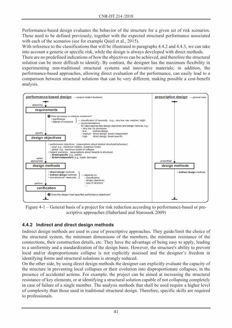
CNR-DT 214 /2018
41
Performance-based design evaluates the behavior of the structure for a given set of risk scenarios. These need to be defined previously, together with the expected structural performance associated with each of the scenarios (see for example Quiel et al., 2015). With reference to the classifications that will be illustrated in paragraphs 4.4.2 and 4.4.3, we can take into account a generic or specific risk, while the design is always developed with direct methods. There are no predefined indications of how the objectives can be achieved, and therefore the structural solution can be more difficult to identify. By contrast, the designer has the maximum flexibility in experimenting non-traditional structural systems and innovative materials; in addition, the performance-based approaches, allowing direct evaluation of the performance, can easily lead to a comparison between structural solutions that can be very different, making possible a cost-benefit analysis.
Figure 4-1 – General basis of a project for risk reduction according to performance-based or pre-
scriptive approaches (Haberland and Starossek 2009)
4.4.2 Indirect and direct design methods Indirect design methods are used in case of prescriptive approaches. They guide/limit the choice of the structural system, the minimum dimensions of the members, the minimum resistance of the connections, their construction details, etc. They have the advantage of being easy to apply, leading to a uniformity and a standardization of the design basis. However, the structure's ability to prevent local and/or disproportionate collapse is not explicitly assessed and the designer’s freedom in identifying forms and structural solutions is strongly reduced. On the other side, by using direct design methods the designer can explicitly evaluate the capacity of the structure in preventing local collapses or their evolution into disproportionate collapses, in the presence of accidental actions. For example, the project can be aimed at increasing the structural resistance of key elements, or at identifying a structural solution capable of not collapsing completely in case of failure of a single member. The analysis methods that shall be used require a higher level of complexity than those used in traditional structural design. Therefore, specific skills are required to professionals.

CNR-DT 214 /2018
42
Paragraphs 4.5 and 4.6 show a detailed description of direct and indirect design methods.
4.4.3 Generic or specific risk assessment Generic risk methods are used when:
a. accidental actions are not defined and / or quantified; b. the effects of accidental actions are not defined and / or quantified.
In case a), some actions (typically equivalent loads) are defined and the project develops through the evaluation of a potential initial damage and its possible evolution in a progressive collapse. In case b), an initial local damage is directly identified (which can result in the complete removal of a member) regardless of the cause that may have provoked it. Then, its possible direct evolution in a progressive collapse is studied. In specific risk assessment, the events and the consequent effects in terms of accidental actions on the structure are quantified and considered explicitly. The structural analysis will have to identify the consequent initial damage and its possible evolution in a progressive collapse. The transition from defining the characteristics of the event to the analysis of the accidental actions may need various multi physical analysis methods, for example in case of fire, explosions, etc.
4.5 INDIRECT DESIGN METHODS Indirect design methods are mainly prescriptive and targeted to obtain robustness by guaranteeing a minimum level of connection between the various components of the structure in order to exploit the redundancy of the system and the ductility of the members in a more effective way. With this approach, the designer requires a limited additional amount of calculation compared to the traditional design. These methods are structural typology dependent, i.e., they are reliable only if applied to those categories of construction, for which the requirements (i.e., limitations, layout of columns and walls, minimum dimensions of the members) were originally defined. Every extension to other fields of application must be done carefully. The prescriptions able to let the structure reach the required level of robustness are limited to the need for continuous connections for a reinforced concrete structure while, for steel or steel-concrete composites structures, beam-column connections and secondary beams-main beams have to be dimensioned in order to transfer not only flexural and shear actions, but also tensile axial stresses. The main objective is to increase the membrane capacity of horizontal elements (beam, slabs) so that the local collapse of a member can be absorbed through a redistribution process, that can also exploit the catenary effect or, more generally, the membrane effect (see Figure 4-2). In particular, three-dimensional ties shall be provided as indicated in Figure 4-3:
peripheral ties in floors (in the two main directions); internal ties in floors (in the two main directions); horizontal ties between columns or walls; vertical ties.
The resistance of these ties depends on the structural system according to the indications provided in Chapter 6. Finally, it should be underlined that indirect design methods do not allow a quantification of the obtained structural robustness.
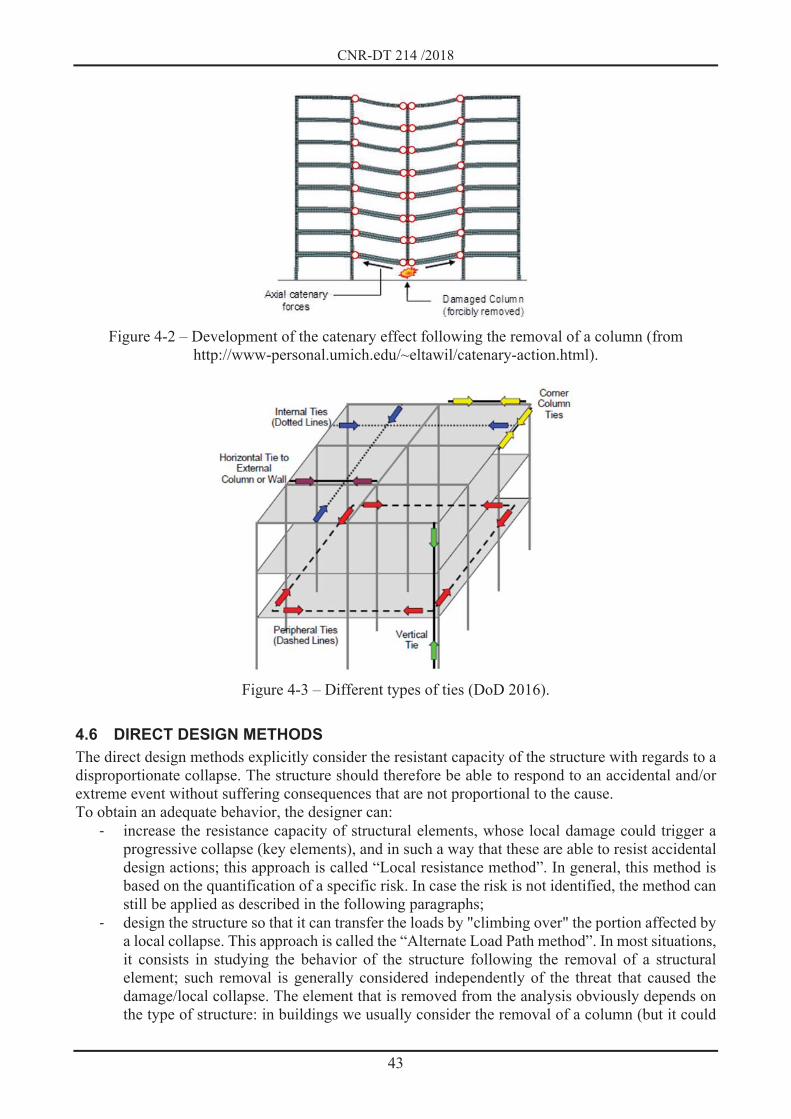
CNR-DT 214 /2018
43
Figure 4-2 – Development of the catenary effect following the removal of a column (from
http://www-personal.umich.edu/~eltawil/catenary-action.html).
Figure 4-3 – Different types of ties (DoD 2016).
4.6 DIRECT DESIGN METHODS The direct design methods explicitly consider the resistant capacity of the structure with regards to a disproportionate collapse. The structure should therefore be able to respond to an accidental and/or extreme event without suffering consequences that are not proportional to the cause. To obtain an adequate behavior, the designer can:
increase the resistance capacity of structural elements, whose local damage could trigger a progressive collapse (key elements), and in such a way that these are able to resist accidental design actions; this approach is called “Local resistance method”. In general, this method is based on the quantification of a specific risk. In case the risk is not identified, the method can still be applied as described in the following paragraphs;
design the structure so that it can transfer the loads by "climbing over" the portion affected by a local collapse. This approach is called the “Alternate Load Path method”. In most situations, it consists in studying the behavior of the structure following the removal of a structural element; such removal is generally considered independently of the threat that caused the damage/local collapse. The element that is removed from the analysis obviously depends on the type of structure: in buildings we usually consider the removal of a column (but it could

CNR-DT 214 /2018
44
also be a truss, a brace, etc.); in case of cable-stayed, suspended or arched bridges generally it is a forestay / pendulum.
This method can also be seen as a tool for evaluating structural redundancy (in terms of load paths) rather than as a structural response simulation technique following initial damage. It should be specified that, in general, direct methods require more complex analysis techniques compared to those used in traditional structural design, therefore it is clear that these approaches require the supervision of experienced professionals. Unlike indirect design methods, direct design methods can require deep structural analyses with more complex techniques compared to those used in traditional structural design. Thus, the designer will have to be able to identify the most suitable analysis tool in relation to the information required from the analysis according to his skills, also considering that simpler methods are generally more immediate than the more sophisticated ones (Ellingwood et al., 2007).
4.7 METHODS OF REDUCTION OF THE ACCIDENTAL ACTIONS AND OF THE EXPOSURE OF THE STRUCTURE TO ACTION
The reduction of an accidental action and/or the exposure of the structure to it, represents, if possible, the first level to be implemented in order to obtain the reduction of progressive collapse. As already mentioned in previous paragraphs, these are generally non-structural aspects which need a detailed definition of the threat to be carried out. Regardless of the accidental action that is expected on the structure, the risk reduction can be achieved through two different ways:
by modifying the interaction between the natural/anthropic phenomenon and the structure, and consequently modifying the structure in such a way that the intensity of the action is reduced;
by intervening on the phenomenon itself, by controlling or monitoring its causes and the method of propagation in such a way that reduces the structure's exposure to the action.
Table 4-1 summarizes, for each of the accidental events introduced in Chapter 2, the possible solu-tions that can be adopted to reduce the accidental actions, distinguishing between:
the introduction of disposable parts to protect the elements themselves. Into this category we can consider the protection against fire of a structural element through the use of a fireproof barrier (which will eventually need to be restored following the event), the protection of the columns with shock-absorbing elements in the presence of moving machines inside of the building, or the use of damageable surfaces to vent the overpressure in case of explosions in confined spaces;
the choice of a shape not very sensitive to a particular action (a solution suitable in case of fluid-structure interaction);
the use of technological solutions aimed at controlling the action. Such an approach can be used for fire protection (sprinkler) or to prevent freezing by heating, where possible, part of the structure in order to prevents the ice formation;
the installation of non-structural (NS) protection elements, such as paneling, railings, break-out windows, energy dissipating elements.

CNR-DT 214 /2018
45
Table 4-1 – Solutions aimed at reducing the size of accidental actions
Disposable parts
Shape of the interested element not sensitive to the action
Use of technological
solutions
Protection on structure with NS elements
Phenomena induced by seismic action Earthquake Tsunami X
Natural gravitational phenomena Landslides of loose material Debris flows Rock collapses X Snow avalanches X Volcanic eruptions
Foundation subsidence Mudslides Changes in groundwater level
Floods and flooding X
Meteorological phenomena Tornadoes and storms X X X Ice formations X
Fire and detonations Fire X X Detonations free environment Confined room detonations X
Impacts Impact of motor vehicles X Impact of boats X Aircraft impact X
Vandalism and terrorist acts X X
Conception, design errors and execution
Table 4-2 summarizes the solutions that can be adopted to reduce the exposure of the structure to the action. They include:
the installation of monitoring systems aimed at assessing the factors that expose the structure to the phenomenon. If the monitored values exceed the values of previously defined threshold, it will eventually be possible to put in place some evacuation procedures;
the control of the factors predisposing to the phenomenon allows to prevent the occurrence of the phenomenon itself or, at least, to limit its size. For example, a suitable drainage allows to prevent the triggering of landslides, the installation of snow-stop structures limits the volume of avalanches, riveting and scaling on walls control rock collapses. For detonation risks, for example, it is possible to eliminate the presence of gas systems inside the building;
the installation of protection systems in the propagation zone of the phenomenon. Into this category, we can consider the bridles for the debris flows, the barriers and the reinforced embankments for the rock collapses, the deviators for the avalanches of snow, the dams for the tsunami. To limit the exposure of the structure to actions deriving by detonation in a free

CNR-DT 214 /2018
46
environment it is possible to install traffic bollards in the surrounding areas in order to not allow vehicles potentially explosive to approach the building;
the positioning of protective systems in the proximity of the building, such as components that are not part of the structure and are disposable (i.e., can be damaged as a result of the occurrence of the phenomenon).
Table 4-2 – Solutions aimed at reducing the structure's exposure to action
Monitoring of the factors
predisposing to the phenomenon
Checking the predisposing
factors
Actions in the propagation area of the
phenomenon
Protective systems close to
the building
Phenomena induced by seismic action Earthquake Tsunami X X
Natural gravitational phenomena Landslides of loose material X X Debris flows X X X Rock collapses X X X Snow avalanches X X X Volcanic eruptions X X
Foundation subsidence Mudslides X X Changes in groundwater level X X
Floods and flooding X
Meteorological phenomena Tornadoes and storms X Ice formations
Fire and detonations Fire Fire detonations free environment X X X Confined room detonations X
Impacts Impact of motor vehicles X Impact of boats X Aircraft impact X
Vandalism and terrorist acts X
Conception, design errors and execution X X X
4.8 FRAMEWORK OF POSSIBLE STRATEGIES FOR RISK REDUCTION Figure 4-4 summarizes the three different levels at which it is possible to operate to obtain the reduc-tion of risk, distinguishing between non-structural methods for event control and structural methods for local assessment of the damage and its evolution. The structural methods can be based on a direct (substantially performance-based) design or indirect (substantially prescriptive-based) design, oper-ating with both specific and generic risk.

CNR-DT 214 /2018
47
Figure 4-4 – General scheme for risk reduction (Haberland and Starossek 2009)
4.9 REFERENCES ASCE/SEI 7-05, ASCE Standard (2006). Minimum design loads for buildings and other structures. American Society of Civil Engineers, Reston, Virginia. Department of Defense (DoD) Unified Facilities Criteria (UFC-04-023-03) (2016). Design Building to Resist Progressive Collapse. Washington, D.C. Ellingwood B. R., Smilowitz R., Dusenberry D., Duthinh D., Lew H. S., Carino N. J. (2007). NISTIR 7396. Best practices for reducing the potential for progressive collapse in buildings, 171-194. Haberland M., Starossek U., Progressive Collapse Nomenclature (2009). Structures Congress 2009: Don't Mess with Structural Engineers: Expanding Our Role. Edited by L. Griffis; T. Helwig; M. Waggoner, M. Hoit, ASCE. Quiel, S. E., Marjanishvili, S. M., Katz, B. P. (2015). Performance-based framework for quantifying structural resilience to blast-induced damage. Journal of Structural Engineering; 142(8), C4015004.

CNR-DT 214 /2018
48
5 CONCEPTS AND CRITERIA FOR ROBUSTNESS
5.1 PREFACE The reduction of risk of a progressive collapse can be obtained with a proper design of the structure. Each of the aspects mentioned in the following will help to limit the propagation of the damage and, as a whole, increase the robustness of the structure:
Redundancy: isostatic structures do not offer the possibility of remedying damage to a member by generating an alternative load path. Statically external and internal (e.g. two-dimensional structures) indeterminate structures increase the possibility of dealing with local damage;
Ties: the loss of principal structural elements can lead to redistribution of stresses and large displacements. The presence of a three-dimensional tie system increases the structure's ability to exploit structural redundancy;
Ductility: together with structural redundancy, it allows structural elements to withstand large displacements and/or rotations without excessive decrease in load-bearing capacity. The actions required to increase ductility depend on the material of the structure and will be detailed in the following chapters;
Uniform distribution of structural elements (columns, walls, beams): structural regularity (i.e., uniform distribution of stiffnesses, resistances and masses) is a fundamental characteristic of the building to allow the loads redistribution in the case of failure of a single member; hence, discontinuity in the path of loads and concentrated loads (e.g. in correspondence of transfer girders) should be limited;
Adequate resistance to tangential stresses: the shear resistance should always exceed the flexural capacity of the members in order to activate the ductile response of an individual member first and then of the whole structure; likewise, the collapse due to punching should be avoided also in the case of loss of a main vertical element;
Ability to resist to the inversion of actions: all the structural elements shall have an adequate resistance to the possible reversal of the sign of variable actions (e.g., in the case of explosions). The collapse of a single structural element can also cause the inversion of the sign of the internal actions with respect to the traditional design situation (see Figure 5-1: the beams above the collapsed column are subjected to positive moment instead of negative one).
5.2 LOCAL RESISTANCE METHOD (KEY ELEMENTS DESIGN) The local resistance method aims at preventing the triggering of an eventual progressive collapse, avoiding local damage to those elements whose collapse would lead to an uncontrolled propagation of damage (key elements). This strategy leads to an increase in system’s robustness by reducing the risk of progressive collapse with measures or interventions that reduce the probability of local damage, conditioned by the occurrence of the event H. This strategy concerns the second term of equation (3.2). The method is often used in presence of structural typology in which the establishment of an alternative path of the loads appears unlikely and are therefore more sensitive than others to local damage; this is typical, for example, of structures with reduced level of redundancy such as tensile structures, reticular structures (flat or spatial), cable-stayed and suspended structures.

CNR-DT 214 /2018
49
Figure 5-1 – Effect of the collapse of a column, often modelled as the sudden removal of the ele-
ment (Izzuddin et al., 2007) Another typical case of application of this method is the design of a transfer girder (Figure 5-2) in which, given the span of the transfer beam and the absence of some columns at the ground floor, the loss of a column can evolve into a progressive collapse.
Figure 5-2 – Building with transfer girders (Kokot and Solomos, 2012)
With reference to the classifications previously indicated, the local resistance method can be considered as a direct method. The action can be specific or generic. In the case of a specific action (quantity of explosive, type of impact in terms of mass, speed and direction of the impacting vehicle, fire load, etc.), the analysis can be nonlinear dynamic and, in some cases, even multi-physical (thermo-mechanical analysis or fluid-structure interaction). In the case of a generic action (by defining a notional value), the analysis can also be nonlinear static. In any case, it has to be considered a direct design method. However, if local resistance is attained without an explicit calculation, but only with prescriptive constructive details, it can be seen as an indirect calculation method. The approach requires that the key element is designed to resist the threats identified previously through one of the following alternative ways:
individually, that is, without recalling the contribution of other structural elements; by recalling the contribution of other structural elements involved in the same resisting
mechanism. Applying the second approach, members (and related connections) that connect the key element with the other structural elements that contribute to the resisting mechanism, shall be designed so as to
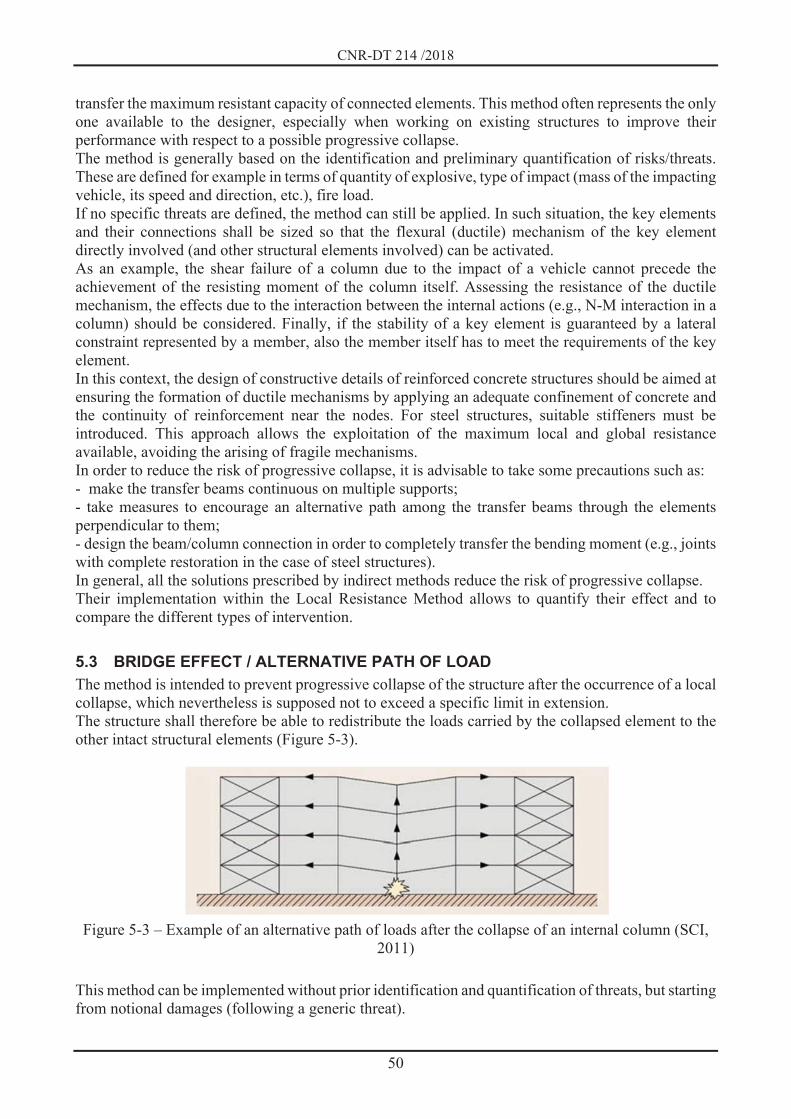
CNR-DT 214 /2018
50
transfer the maximum resistant capacity of connected elements. This method often represents the only one available to the designer, especially when working on existing structures to improve their performance with respect to a possible progressive collapse. The method is generally based on the identification and preliminary quantification of risks/threats. These are defined for example in terms of quantity of explosive, type of impact (mass of the impacting vehicle, its speed and direction, etc.), fire load. If no specific threats are defined, the method can still be applied. In such situation, the key elements and their connections shall be sized so that the flexural (ductile) mechanism of the key element directly involved (and other structural elements involved) can be activated. As an example, the shear failure of a column due to the impact of a vehicle cannot precede the achievement of the resisting moment of the column itself. Assessing the resistance of the ductile mechanism, the effects due to the interaction between the internal actions (e.g., N-M interaction in a column) should be considered. Finally, if the stability of a key element is guaranteed by a lateral constraint represented by a member, also the member itself has to meet the requirements of the key element. In this context, the design of constructive details of reinforced concrete structures should be aimed at ensuring the formation of ductile mechanisms by applying an adequate confinement of concrete and the continuity of reinforcement near the nodes. For steel structures, suitable stiffeners must be introduced. This approach allows the exploitation of the maximum local and global resistance available, avoiding the arising of fragile mechanisms. In order to reduce the risk of progressive collapse, it is advisable to take some precautions such as: - make the transfer beams continuous on multiple supports; - take measures to encourage an alternative path among the transfer beams through the elements perpendicular to them; - design the beam/column connection in order to completely transfer the bending moment (e.g., joints with complete restoration in the case of steel structures). In general, all the solutions prescribed by indirect methods reduce the risk of progressive collapse. Their implementation within the Local Resistance Method allows to quantify their effect and to compare the different types of intervention.
5.3 BRIDGE EFFECT / ALTERNATIVE PATH OF LOAD The method is intended to prevent progressive collapse of the structure after the occurrence of a local collapse, which nevertheless is supposed not to exceed a specific limit in extension. The structure shall therefore be able to redistribute the loads carried by the collapsed element to the other intact structural elements (Figure 5-3).
Figure 5-3 – Example of an alternative path of loads after the collapse of an internal column (SCI,
2011)
This method can be implemented without prior identification and quantification of threats, but starting from notional damages (following a generic threat).

CNR-DT 214 /2018
51
Usually, the designer assumes the collapse of a structural element (typically a column), removes it by the structural model and verifies through nonlinear static or nonlinear dynamic analyses that the remaining structure is still able to transfer the actions, considering the accidental load combination. Obviously, the damage can also be assessed following a specific threat whose effect can be the incomplete elimination of the structural element. The method can also be implemented indirectly. This is typical of the use of connecting ties to improve robustness. In this case, the structure is mechanically linked through continuous ties in the three main directions in order to increase continuity, ductility and ability in developing alternative load paths. It allows to use structural resources which are normally not considered in the traditional design, such as the catenary effect. Alternative load paths can designed more easily in structural systems characterized by ductility, structural regularity, redundancy and dissipative capacity. In this way, the risk of progressive collapse is minimized.
5.4 COMPARTMENTALIZATION The method is intended to limit the extent of a progressive collapse due to an initial local failure by isolating the damaged structural part from the remaining structure. The edges of the compartment are constituted by:
"strong" elements that stop the collapse of "weak" elements of the compartment, or: “weak elements” which, collapsing, disconnect the damaged part from the rest of the structure
that remains intact (structural fuses). Like the previous one, the method can be implemented directly following a notional damage or a damage caused by a specific threat, but also indirectly through prescriptive approaches relating to on-board elements.
5.5 REFERENCES Izzuddin B.A., Vlassis A.G., Elghazouli A.Y., Nethercot D.A. (2007). Progressive collapse of multi-storey buildings due to sudden column loss - Part I: Simplified assessment framework. Engineering Structures; 30(5):1308-1318. Kokot S., Solomos G. (2012). Progressive collapse risk analysis: literature survey, relevant construction standards and guidelines. Ispra: Joint Research Centre - Institute for the Protection and Security of the Citizen. ISBN: 978-92-79-27734-4. SCI, Steel Construction Institute (2007) Structural robustness of steel framed buildings. In accordance with Eurocodes and UK National Annexes. Publication number: SCI P391. SCI, Silwood Park, Ascot, Berkshire. SL5 7QN UK. ISBN: 978-1-85942-198-7.

CNR-DT 214 /2018
52
6 DESIGN FOR ROBUSTNESS
6.1 PREFACE The behavior of a structure following an accidental action is a complex phenomenon to be studied, given the high number of variables involved and the uncertainties associated to them. In this context, structural modeling is fundamental. It allows to assess theoretically the level of risk of a possible progressive collapse. However, the accuracy of the results is closely linked to the method of analysis adopted, the type of modeling and the behavior of the materials constituting the structure. Regarding this last aspect, the capacity to absorb and dissipate energy following the formation of a localized damage is directly connected to the constitutive laws of the materials that constitute the structural elements and their connections.
6.1.1 Structural modeling Finite element programs allow to simulate the material behavior using different formulations, from the simplest, in which the behavior is considered linear elastic, to the more complex nonlinear hysteretic ones. In addition, the designer has the possibility to change some parameters that govern these laws. It is therefore clear that the sensitivity and the experience of the designer play a key role in the choice and calibration of the constitutive laws in order to simulate a specific behavior and how carefully these individual parameters are chosen, and the associated structural response is evaluated. Here are some aspects to be considered in structural analyses, both in terms of constitutive laws and modeling:
Linear elastic constitutive models. The linear elastic constitutive models are the simplest to use and easiest to interpret; they are especially useful in the preliminary design phases, when nonlinearities are generally neglected. An initial evaluation based on elastic models can help the designer to highlight any critical issues in structural behavior, which should be solved before proceeding with more complex analyses. Their simplicity can be seen as an advantage from an initial point of view; however, in the following steps, linear elastic models are proven to be unsuitable to study complex phenomena such as a progressive collapse. This is mainly caused by the extent of deformations that makes the behavior of materials highly nonlinear.
Nonlinear constitutive models dependent/independent on load application rate. In general, the study of progressive collapse involves the development of inelastic deformations. The plasticization of the material represents a fundamental contribution in the energy dissipation process and in redistribution of actions. For this reason, it cannot be neglected. It is important to note that the nonlinear behavior of traditionally used materials (concrete, steel, composite materials, masonry, etc...) is represented by the dependence of the constitutive law on the velocity of application of the load, especially if the action time interval is very short (for example in case of explosion or impact of high speed vehicles). This aspect leads to an increase in strength and/or stiffness of materials, an increase which can be taken into account in the evaluation of robustness by means of analytical implementation.
Local models / global models. The study of the structural response can be profitably developed at different levels of complexity. It is not convenient, from a computational point of view a, to create a single model capable of grasping all the aspects of the structural behavior. This is particularly true as far as the management of the outputs is concerned. For this reason, it is helpful to realize both global and local model. The global model is used to derive general information such as the distribution of internal actions. The local model, on the other hand, is suitable to study the behavior of specific regions of the structure (discontinuity areas, load application points, stress concentration areas, nodes, connections, etc...). The use of local models becomes then fundamental in the assessment of construction details behavior for which experimental evidence is not available. For instance, in a global model of the structure,

CNR-DT 214 /2018
53
the mechanical behaviour of a beam-column connection can be transformed into a simpler equivalent nonlinear link, whose moment-rotation law is derived from the local model.
6.1.2 Types of analysis Local damage and / or collapse of a single element can result in the transition from the original configuration to the damaged one in a sudden way. Theis transition generates dynamic effects, which can be considered in different ways, depending on the type of analysis. After the accidental event, some displacements (and consequently deformations) may arise in the structure and the elastic limit of the materials can be overcome. The transition in the plastic field allows to dissipate a part of the energy released following the collapse of the element, thus mitigating dynamic effects. The types of analyses that can be performed are listed below:
a. Linear static analysis: although the structural response following the damage and/or local collapse and the consequent redistribution of loads is a nonlinear dynamic response, in some cases it is possible to evaluate the structural behavior by using static elastic analyses and increasing the effects by means of a suitable dynamic amplification coefficient. This type of analysis has the advantage to be carried out with simple programs and to be managed by moderately experienced designers. In any case, through this approach, the designer does not have the possibility to take into consideration different effects due to:
redistribution of internal actions; P-delta effects (geometric nonlinearity); nonlinear characteristics of the material; catenary / membrane effect.
This type of analysis, when applied for the assessment of structural robustness, generally leads to an approximate solution and, for this reason, should be limited to very simple structures; in other situations, indirect design methods are more appropriated.
b. Nonlinear static analysis: taking into account the geometric nonlinearity due to the large deformations that the structure undergoes as a result of damage and/or local collapse, the catenary effect and/or the membrane effect of the slabs can be properly considered. However, the designer must evaluate the stresses in the members involved (beams and slabs), comparing them with the bearing capacities of them and their connections with the other elements. In this type of analysis, the choice of the type of behavior assumed for the materials and the simulation of the nonlinear behavior of connections (nodes) is of particular importance; in general, it is recommended to set up local models to evaluate the most appropriate choices. In addition, it is important to consider the possible dependence of the results by the mesh used in the computational model. The dynamic effects can generally be taken into consideration using a suitable dynamic amplification coefficient.
c. Linear dynamic analysis: this type of analysis allows to take into account the dynamic effects due to local damage/collapse, but is not able to appreciate the effects related to the nonlinearity of the phenomenon.
d. Nonlinear dynamic analysis: it represents the most complete and suitable type of analysis to simulate the problem. The calculation is usually performed using three-dimensional models, nonlinear, taking into account large deformations and the behavior during the transient phase. However, not all the computational programs are capable to perform this kind of study. Due to the complexity and the large number of parameters involved, this type of analysis can only be carried out by experienced designers. The computational effort of these studies can be very high, especially in case of large structures.
As for the dynamic amplification coefficient used in static analysis, it is possible to refer to Table 6-1 for the more frequent typologies, in which p indicates the plastic rotational capacity (with respect to the chord) of the element/component/connection and y represents the corresponding rotation (always with respect to the chord) at yielding. In the evaluation of the ratio p/ y, it is necessary to refer to the

CNR-DT 214 /2018
54
smallest value among the elements/components/connections who are affected by nonlinear behavior (DoD, 2016)
Table 6-1 – Dynamic amplification coefficient as a function of the structural type (DoD,2016)
Material Structural type Coeff. dynamic amplification Steel Framed structures 1.08 + 0.76/( p/ y + 0.83)
Reinforced concrete Framed structures 1.04 + 0.45/( p/ y + 0.48) Wall structures 2.0
Masonry Wall structures 2.0 Wood Wall structures 2.0 Cold bent steel profiles 2.0

CNR-DT 214 /2018
55
6.2 REINFORCED CONCRETE BUILDINGS
6.2.1 Preface Cast-in-situ reinforced concrete (RC) structures present several advantages when subject to accidental and/or extreme events for several reasons:
structural continuity (and the consequent redundancy) can be easily obtained; even if concrete in compression has a reduced ductility, it is easy to obtain a ductile behavior
of sections and members subject to bending actions using appropriate construction details; the size of the columns makes them less susceptible to buckling even in the case of loss of a
single floor restraint; the significant mass of the structure improves its response in case of explosions, because the
mass is often mobilized in a second phase, when the shock wave of the explosion has already undergone a significant reduction.
On the other hand, the large mass of the structure sometimes makes it difficult to plan suitable interventions to ensure the robustness of the system with regard to the occurrence of local damage, due to the large forces that must be conveyed on an alternative load path. The resisting brittle mechanisms (such as shear, torsion, anchoring and overlapping of reinforcements) can inhibit the development of ductile mechanisms. Thus, they should be avoided by using a capacity design approach (hierarchy of strengths between brittle and ductile modes), similar to the design methods used in the presence of seismic-type actions. This section will deal with framed RC structures, while wall structures will be briefly discussed in paragraph 6.3.4.
6.2.2 Collapses in reinforced concrete buildings The scientific literature provides numerous examples of collapses in RC buildings due to accidental actions (Feld and Carper, 1997). In many situations, the collapses of RC buildings occurred due to seismic actions, typically when these structures were originally designed with regard to gravity loads only. However, there are a number of collapses due also to other actions, as reported in the following examples. A first important case of collapse of a cast in situ RC building is that of the Murrah Federal Building (MFB), which was the main target of the explosion that took place in 1995 in Oklahoma City. The building consisted of nine floors above ground with a plan size of 67 m × 30 m. The structure of the building was an ordinary cast-in-situ RC frame with columns, beams and one-directional floors. The structural plan with the position of the columns and their nomenclature is shown in Figure 6-1. The resistant system to horizontal actions consisted of RC shear walls positioned on the south side of the building in correspondence to stairs and elevators. The north side of the building instead presented a fully glazed facade in correspondence with the row G of columns (Figure 6-1 and Figure 6-2). The explosion occurred at the north side of the building near the column G20. Some analyses estimated that the explosion corresponded to the detonation of about 1800 kg of TNT. According to some authors (Sozen et al., 1998), the explosion caused the collapse of the G20 column and the subsequent shear collapse of the columns G16 and G24. Due to the loss of these three intermediate supports, the beam that supported the upper portion of the building on the west side failed causing a phenomenon of progressive and disproportionate collapse (Figure 6-2 and Figure 6-3). This hypothesis of collapse seems to be shared by numerous authors (FEMA, 1996; Kazemi-Moghaddam, 2015), although some argue that this collapse could not have been activated exclusively by the collapse of column G20, but that a greater initial damage must be associated to this event. In fact, the activation of alternative resistant mechanisms, such as catenary action in the beams and Vierendeel beam behavior of the frame system of the upper floors (Kazemi-Moghaddam, 2015) should have avoided the full collapse in the case of a local collapse, i.e. column G20 only.

CNR-DT 214 /2018
56
Figure 6-1 – Plan of the building with grid of the columns and location of the explosive charge
(adapted from Kazemi-Moghaddam, 2015)
Figure 6-2 – Aerial view after the collapse of the building and the glass facade on the north side
(from https://commons.wikimedia.org/wiki/File:Murrah_Building_-_Aerial.jpg)

CNR-DT 214 /2018
57
Figure 6-3 – Close-up view of the building after the collapse (from https://commons.wiki-
media.org/wiki/File:Oklahomacitybombing-DF-ST-98-01356.jpg) As a second example, the collapse of a concrete building involved two thirds of a 16-story apartment building under construction in Boston, Massachusetts on January 25, 1971. The structure of the building was almost completed at the time of the collapse. The building consisted of floor slabs cast-in-situ and a central core for the lift (Figure 6-4). The floor slabs had a thickness of 190 mm except for some spans near the lift and stairs with a thickness of 230 mm. As reported by King and Delatte (2003), the collapse of the roof due to punching triggered a progressive and disproportionate collapse up to the basement. Fortunately, the collapse occurred quite slowly allowing most workers to escape and thus resulting in a limited number of victims. The commission appointed to establish the causes of the collapse concluded that it would not have occurred if the construction had been realized in accordance with the project, highlighting numerous shortcomings both in the construction procedures and in the quality of the materials used. The main causes of the collapse due to punching were attributable to the following factors: a) the inadequate provisional supporting system of the roof slab and b) the low strength of the concrete, also related to the inadequate protection against the cold climate during the concrete curing phase.

CNR-DT 214 /2018
58
Figure 6-4 – Extension of the collapse in the building under construction in Boston, Massachusetts
(readapted from King and Delatte, 2003) A third example of partial collapse happened during the L'Aquila earthquake on April 6, 2009 (Mulas et al., 2013; Mulas and Martinelli, 2017), involving a RC building sadly known as Student House. The building was designed in the early 1960s and was characterized by two underground floors and five above-ground floors, with a framed structure. The planimetric distribution show the presence of three separated wings, as shown in Figure 6-5. The collapse affected the north wing, where all the columns at the ground floor and three columns located at the connection with the other wings collapsed on their own weight (Figure 6-6)). The col-lapse is mostly attributable to the incorrect structural conception characterized by gross underestimate of the seismic forces acting in the North-South direction. The overall capacity of the structural ele-ments (frames) arranged in the N-S direction was in fact less than half the capacity of the structural elements arranged along the orthogonal direction.
Figure 6-5 – Planimetric view of the building with indication of the collapsed portion. The col-
lapsed columns along the entire length are highlighted with a red circle

CNR-DT 214 /2018
59
Figure 6-6 – Student house before the demolition of the collapsed wing: a) soft story mechanism in the North Wing; b) Collapse of the columns at the connection between the North Wing (right) and
the other wings of the building (left). (adapted from Mulas and Martinelli, 2017)
6.2.3 Alternative path of loads and membrane effects in reinforced concrete buildings
Membrane action effects may significantly contribute to the structural robustness of RC members such as beams and slabs. The dependency of membrane actions on geometrical features of members and mechanical properties of materials has been investigated over the time. A fundamental geometrical parameter is the slenderness of the members, the ratio between the length of the element and the height of its transversal cross section. The reinforcement ratio and the mechanical properties of concrete and steel are also important parameters.
6.2.3.1 Reinforced concrete elements: membrane effects In beam-like elements, the so-called membrane effect consists in the arise of an axial stress condition with a consequent beneficial effect on the resistance of elements under flexure when subject to large displacements. In slab-type elements, the membrane effect gives rise to radial and tangential stress. Figure 6-7 highlights how the beneficial effect of membrane stresses can be exploited not only in the case an accidental event such as the collapse of a column (Figure 6-7b), but also for loads higher than those considered in the design phase (Figure 6-7a). In particular, Figure 6-7a shows a continuous floor subject to distributed applied loads and restrained conditions at the extremities. Figure 6-7b instead shows the example of the full collapse of a column in a continuous floor. Figure 6-7c qualitatively illustrates, for both cases reported in Figure 6-7, the structural response in terms of deflection (f) of the floor versus distributed load graph (q). It shows that the contribution of the membrane action in the geometric non linear field can be very different from that of the structure where these effects are neglected. Membrane effects and geometric nonlinearity produce an increase in resistance in the structural response. In the first stage, compressive membrane stresses are usually observed in RC cast in situ elements, due to the elongation of the central axis of the element when cracking arises, while tensile membrane stresses arise after the plasticization of the cross-sections. Compressive membrane stresses can be more or less relevant, depending on the slenderness of the structural elements involved. In general, membrane stresses may be relevant in determining the capacity of the structural elements with regard both to fragile mechanisms (such as shear or punching failures) and to ductile mechanisms (such as flexural failures).

CNR-DT 214 /2018
60
Figure 6-7 – Membrane stresses in structural elements: a) collapse of continuous floor for loads
higher than those considered in the design phase; b) collapse of a column in a continuous floor; c) deflection - distributed load graph.
For short spans, the compressive membrane forces are already activated in the case of limited deformations. In case of long spans, the compressive membrane forces are negligible, while the tensile ones contribute significantly to the resistance of elements under flexure. It should be noted that the effects of shrinkage and creep, as well as the existing cracking state, can significantly affect the value of the compressive membrane actions. On the contrary, the tensile membrane stresses do not depend significantly on the deformation in concrete but depend on the ultimate deformations of the reinforcement bars and on the geometric reinforcement ratios. Therefore, it is worth remembering that, for existing structures, endogenous or exogenous degradation, cracking due to pre-existing loads and other phenomena can significantly modify the redistribution of the actions, the stiffnesses and/or the mechanical properties of the materials, on which the membranes stresses depend. For example, the reduction of the ultimate deformation of the reinforcing bars due to the corrosion can greatly reduce the "catenary" effect in case of tensile membrane stresses (Botte et al., 2015). The membrane stresses depend substantially on the constraint conditions: the condition of fixed constraints defines the upper limit for the membrane stresses, which decreases when the stiffness of the external restraints is reduced. Due to the structural continuity, membrane stresses never wear out, and are also present in elements without any constraint to lateral translation (Cantone et al., 2016). The scientific literature (Qian et al, 2014) shows that the presence of RC floors or slabs can significantly contribute to the development of membrane forces, by amplifying the effects previously described for the case of only RC beams. In case of continuous RC floors, Figure 6-8, although the prevention of lateral displacement is limited (depending on column stiffness), the membrane effect is of particular interest and contributes, together with the redistribution of the bending moment, to an increase in flexural, shear and punching resistance of these structural elements. Figure 6-8 illustrates the case of a continuous floor subject to a distributed load. The membrane stress is generated in the plane of the slab after the cracking of the extrados (of the slab) near the column, that is in correspondence of the maximum negative bending moment, Figure 6-8(a) (Belletti et al., 2018). The different stiffness characterizing the non-cracked part, with respect to the cracked one,

CNR-DT 214 /2018
61
generates a constraint to the radial expansion of the cracked part consisting in a tangential stress ring, Figure 6-8(b), self-equilibrated with a radial compressive condition. Paragraph 9.1 shows an example of a finite element analysis on a RC slab, in which the membrane effects were quantified.
Figure 6-8 - (a) - Bending moment diagram; (b) - Compressive membrane forces near to the col-
umn; (c) Rotation of the slab; (d) critical perimeter; (e) Critical Shear Crack Theory (CSCT) failure criterion (Belletti et al., 2018)
6.2.3.2 Evaluation of membrane effects Over the past 50 years, various experimental campaigns have been conducted to investigate the effect of membrane stresses on RC elements but, due to the complexity of the problem, only few Standards presently considered this phenomenon (for example, the British Standard, BD 81/02, 2007). The role of membrane effects, therefore, has a very little consideration in professional practice, where very conservative theories are usually adopted. Actually, various experimental and numerical studies show that membrane effects can produce favorable effects both in terms of flexural resistance and shear / punching resistance of continuous slabs (Gvodzev, 1936; Braestrup, 1980; Vecchio and Collins, 1990). The study of membrane action effects can be addressed in two different directions: the increase in the capacity of RC beams and slabs subjected to overpressure or overloading; the increase in the capacity of RC beams and slabs in the case of removal of a vertical support. Analysis of membrane action in RC beams and slabs subjected to overpressure or overloading In general, the presence of membrane actions can be favorably considered in the analysis of the nonlinear behavior of bridge slabs (Taylor et al., 2007; Rankin et al., 1991; Salim and Sebastian, 2003; Belletti et al., 2015; Amir et al., 2016; Rankin and Long, 1997), in slab - column connections (Rankin et al., 1987; Belletti et al., 2016), in offshore structures, in underground structures subject to soil pressure, in slabs subject to fire load (Dat and Hai, 2013).

CNR-DT 214 /2018
62
In the 1970s, several tests (Hewitt and Batchelor, 1975) were carried out by the Ontario Ministry of Transportation, that allowed to insert empirical formulations in the Highway Bridge Design Code (OMTC, 1979) to take the membrane effects into account. In UK, Rankin and Long (1997) developed an elasto-plastic method to evaluate the increase in resistance due to the arc effect in one-dimensional plates (Taylor et al., 2003). The 2002 British Code (British Standard BD81/02) presents a simplified method for calculating the compressive membrane actions on the ultimate local capacity of laterally restrained deck slabs. The predicted ultimate load , / (N) for a single loaded area can be evaluated as:
where is the diameter of the loaded area (mm), d is the effective depth (mm) of the cross section of the slab, fcd is the design compressive strength of concrete (N/mm2) and e is an effective reinforcement ratio equivalent to the membrane effects, calculated according to the equation:
where h is the overall slab depth (mm) and the non-dimensional parameter k is calculated according to the equation:
with the non-dimensional parameter R equal to:
being Lr half span of slab strip with boundary restraint, and the plastic strain of an idealised elastic-plastic concrete:
where fcd is the design compressive strength of concrete (N/mm2). This equation is valid in case of elasto-plastic behavior of concrete up to 70 N/mm2 strength. The British Standard BD81/02 establishes several limitations on the use of the previous formulations. For example, in bridge decks the transverse (primary) span length of a slab panel perpendicular to the direction of traffic should not exceed 3.7 m. The slab shall extend at least 1.0 m beyond the centre line of the external longitudinal supports of a panel. In the case of an external panel, a kerb or string course integral with the slab may be used instead of the 1.0m overhang, provided that the combined cross-sectional area of slab and curb, beyond the centre line of the external girder, is not smaller than the cross-sectional area of one meter length of deck slab. Moreover, the span length to thickness ratio of the slab should not exceed 15, and the minimum reinforcement ratio is 0.3%. Obviously, the basic hypotheses on which the formulations are based (such as those provided by British Standard BD81/02) hardly adapt to the variety of cases characterizing the engineering practice. Therefore, the use of nonlinear analysis could be required for a more precise evaluation of flexural and shear resistance of RC elements, with beam, membrane, solid brick or shell elements for modeling. The evaluation of membrane actions requires finite element models with equilibrium conditions imposed in the deformed configuration of the structure (geometric non linearity), together with mechanically nonlinear constitutive models. From one side, the research is presently focusing on the evaluation of model uncertainties associated with the use of nonlinear finite element (for the assessment of structural robustness) and, from
, / 1.52 100 . (6.1)
240 (6.2)
0.0525 4.3 16.1 3.3 10 0.1243 (6.3)
(6.4)
400 60 0.33 10 (6.5)

CNR-DT 214 /2018
63
another, on the calibration of finite element models in order to let them to consider the static and dynamic aspects that characterize the membrane effects. In parallel, design methods that allow a simplified calculation in the professional practice are under development. Analysis of membrane action in RC beams and slabs subjected to vertical support removal Membrane actions are of fundamental importance in structures subject to a sudden removal of a column. In general, compressive membrane actions increase the flexural capacity for low values of vertical displacement, while tensile membrane actions - provided by continuous reinforcement – characterize the behavior at the catenary stage. Membrane actions can be evaluated by using analytical approaches or nonlinear finite element analyses (Belletti et al., 2016b; Galmarini, 2014; Botte et al., 2015, Belletti et al. 2019). Several models are available in literature, for example a simplified analytical method for the evaluation of the compressive arch action for frame structures has been presented by Abbasnia et al. (2016). The progressive collapse response of a beam-slab RC system can be analysed by the analytical formulation proposed by Pham and Tan (2019). In this regard, a simplified method is reported in Appendix A for the evaluation of the ultimate load-bearing capacity of RC slabs in case of a sudden removal of one or more columns. A numerical example using the method in Appendix A is illustrated in chapter 9.
6.2.4 Ties As introduced in the previous section, an adequate behavior against a progressive collapse can be obtained by designing suitable ties within the structure to ensure the correct development of the membrane effect at the floor level. In particular, according to Figure 4-3, and with reference to a building with a rectangular plan, four types of ties can be provided (peripheral ties, internal ties, horizontal ties - between columns or walls - and vertical ties). The international standards quantify ties in substantially different ways, demonstrating that the topic is still under development. In the following, two formulations are reported: the first is related to EN1992-1-1 (CEN 2004), while the second is related to UFC 4-023-03 (DoD, 2016).
6.2.4.1 Ties according to Eurocode 2 (CEN 2004) Eurocode 2 (CEN 2004) gives indication for design of ties in Chapter 9.10, as summarized in Figure 6-9. The quantity of reinforcement, resulting from the formulations below, shall be considered as a minimum quantity and not as an additional reinforcement to that required by structural analysis. From a general point of view, it can be observed that, in most cases, these reinforcements are quite small, and generally smaller than those deriving from an ordinary design. Peripheral ties in floors. A continuous peripheral tie shall be provided at each floor and roof level within 1.2 m of the floor edge, able to resist a tensile force of:
being L the length of the final span in meters. The same ties shall be provided also along the edge of any internal openings (such as halls, courtyards, etc.).
Fper = 10 kN/m L 70 kN (6.6)

CNR-DT 214 /2018
64
Figure 6-9 – Different ties as reinforcement of a floor slab (CEN 2004)
Internal ties in floors. Continuous internal ties shall be provided at each floor and roof level in two orthogonal directions; such ties must be effectively anchored at both ends to the peripheral ties or to columns and walls. In each direction, internal ties shall be able to resist a design value of tensile force per unit width Ftie,int/m (in kN/m):
In floors without screeds, where ties cannot be distributed transversely to the floor secondary beams, transversal ties can be grouped along the beams and/or cross beam joist; in this case, the minimum on an internal beam line is:
being L1, L2 the span lengths (in meters) of the floor slabs on the two sides of the beam (see Figure 6-9). Horizontal ties to columns and/or walls. Edge columns and walls should be tied horizontally to the structure at each floor and roof level. Such ties shall be able to resist a tensile force (per horizontal meter of façade) equal to 20 kN/m; for columns the force must not exceed 150 kN. In corner columns, ties shall be provided in two directions, with the possibility to use the peripheral tie as a horizontal tie. Vertical ties. In cast-in-situ buildings, vertical tying is guaranteed by the continuity of the longitudinal reinforcement of the columns, so no specific reinforcement is required in addition to these. The forces previously indicated can be absorbed referring to the characteristic strength of reinforcements (partial factors equal to 1.0). Finally, if the building is divided into portions that are structurally independent, the ties have to be provided for each part separately. It should be noted, however, that some numerical simulations leave several doubts on the adequacy of such quantities of reinforcement to prevent a disproportionate collapse by the activation of a catenary effect.
Ftie,int/m = 20 kN/m (6.7)
Ftie = 20 kN/m (L1+L2)/2 70 kN (6.8)
peripheral ties internal tie horizontal column or wall tie
L 2
L 1

CNR-DT 214 /2018
65
6.2.4.2 Ties according to Unified Facilities Criteria (UFC) 4-023-03 In addition to the described formulations, the report from the United States of America Department of Defense is presented. It can be observed that the reinforcements resulting from that approach, applicable to framed structures with at least 4 spans in each direction, are greater than those provided by the British standard, resulting, in most situations, in a reinforcement increase, compared to the design for non-accidental actions. Chapter 3 of the UFC defines the quantities of ties to be considered in order to guarantee a minimum level of continuity, ductility and redundancy to the entire structure. The document establishes that, in order to evaluate the minimum quantity of reinforcement, the designer must define firstly the distributed floor load wF through the following relationship:
where D indicates the distributed permanent load and L the variable load. The floor load combination corresponds to the accidental combination in European Guidelines for design. Peripheral ties in floors. A continuous peripheral tie shall be provided at each floor and roof level within 1.0 m from the edge of the floor. For framed and two-way load-bearing wall buildings, the required peripheral tie strength Fp (in kN) is:
where: wF is the distributed floor load previously defined; Wc (in kN) is equal to 1.2 times the permanent load due to the presence of the infill of span L1
(where 1.2 is the safety factor associated with the load in US Guidelines); L1, in case of peripheral ties placed on the edge of the building, is the greatest distance between
the columns in the direction considered while, in case of peripheral ties placed at the openings, L1 is equal to the length of the span in which the opening is located, in the considered direction;
Lp is equal to 1.0 m; Internal ties in floors. A distributed internal tie connection shall be provided at each floor and roof level within 1.0 m from the edge of the floor. The required tie strength per unit width Fi/m (in kN/m) in the longitudinal or transverse direction is:
where: wF is the distributed floor load previously defined; L1 is the greatest distance between the columns supporting two adjacent floors in the
considered direction. Vertical ties. In cast-in-situ buildings, vertical tying is guaranteed by the continuity of the longitudinal reinforcement of the columns, so no additional specific reinforcement is required. Strength of ties shall be calculated considering a design tensile strength at least equal to the largest stress transferred in vertical direction from one of the columns. This load can be obtained multiplying the floor load wF by the area of competence of the column. Construction details. Construction details are fundamental to guarantee an adequate behavior of the ties. In particular, a resistance of the anchoring tie bar greater than the resistance to yielding of the tie bar itself shall be guaranteed. The hypothesis of continuity of the tie bars requires that an overlapping of the bars or anchoring lengths of longitudinal bars are properly dimensioned.
1.2 0.5 (6.9)
6 3 (6.10)
/ 3 (6.11)

CNR-DT 214 /2018
66
Comprehensive information and indications regarding the correct positioning of the ties and the construction details for the realization of the tie bars can be found in the document UFC 4-023-03.
6.2.4.3 Simplified methods for structural sub-assemblages In the literature, several simplified methods have been proposed for the analysis of the nonlinear response of structural sub-assemblages in the case of a column loss. The progressive collapse mechanisms of sub-assemblages of RC frames have been analysed by Jian et al. (2014) and Naji (2017). These methods are able to predict the nonlinear response on structural sub-assemblages by providing the vertical load and the vertical displacement corresponding to the formation of plastic hinges at beam ends, the onset of catenary action, the yielding and finally the rupture of longitudinal reinforcement. These methods (see for instance Li et al. 2011) a-priori assume a minimum level of ductility able to allow the formation of catenary action. A comparison between the tie demand values evaluated on the basis of different approaches and code formulations is presented in Belletti et al. (2019). Figure 6-10 shows that, through simplified methods, the tie demand can be accurately predicted, while EN1992-1-1 underestimates the tie demand if compared with experimental results.
Figure 6-10 – Comparison between experimental results, code formulations and analytical simpli-
fied methods
6.2.5 Structural behavior towards the removal of a column The structural behavior of RC framed buildings subject to a removal of a vertical load-bearing element can be described by defining the various phases of its behavior as a function of the vertical displacement that can be mobilized at the section in which the column is removed. The various phases are described below with reference to the experimental test shown in Figure 6-11 (Lew et al., 2011), representing a two-dimensional RC frame where the removal of a non-edge column have been considered. The prototype is subject to an imposed displacement in correspondence of point P1, to simulate the loss of the column.
L LTiedemand
Tiedemand
P
0
200
400
600
800
1000
1200
1400
1600
1800
2000
0 100 200 300 400 500 600 700 800
TieDe
man
d[kN]
Vertical Load P [kN]
UFC
EC2
Naji method
Jian method
Experimental results

CNR-DT 214 /2018
67
Figure 6-11 – Element subject to experimental test simulating the loss of a column
The experimental behavior is represented in Figure 6-12 in terms of force applied to the point P1 (Figure 6-12a) and horizontal displacement of point P2 (Figure 6-12b), both as a function of the ver-tical displacement imposed at point P1. The analysis of the experimental behavior allows to identify three different stages. The first stage (from O to A) indicates a flexural behavior of the beam and ends with the formation of plastic hinges at the beam-column connections (achievement of the negative plastic moment in the beam at the side columns, and of positive plastic moment at the removed central column). In this phase, point P2 is subject to a negative horizontal displacement (outwards) due to the cracking of the beam and the consequent partialization of the sections leading to an increase in length in correspondence of the beam centroidal axis; being this increase in length contrasted by the stiffness of the columns, the beam is subject to a compressive action with a consequent increase in the plastic moment. The second stage (from A to B) is characterized by a softening branch with a decrease of the applied force as the vertical displacement of point P1 increases. It can be observed that, when the vertical displacement of point P1 became large enough, the point P2 starts to move horizontally inwards, decreasing up to zero. In that phase, the axial force in the beam decreases up to zero. The third stage (from B to C) is characterized by a new increase in the force applied, as the vertical displacement of point P1 increases. It can be observed that the horizontal displacement of point P2 becomes positive (inwards) and consequently the beam is in traction. In this phase, the load is carried by the beam, with a combination of flexural effect and a catenary effect, by means of the continuous steel reinforcements. The catenary effect gradually increases as vertical displacement of point P1 increases. Obviously, for the catenary effect to establish, a continuous reinforcement must be present between the two columns on sides of the one lost by the accidental and/or extreme event. If this condition does not occur, the maximum load that the structure can bear will be the one corresponding to the flexural behavior only (point A).

CNR-DT 214 /2018
68
(a)
(b) Figure 6-12 – Evolution of experimental behavior of the beam in Figure 6-11: flexural behavior
(O -A), softening branch (A - B), development of the catenary effect (B - C) It should be emphasized that the behavior described above neglects any contribution of structural elements orthogonal to the plane of the frame, such as the secondary beams supported by the lost column in P1 and the floor slabs. The maximum load related to the structure that activates the flexural behavior PMAX,FL (point A) and the one corresponding to the catenary behavior PMAX,CAT (point C) can be easily calculated, with simplified hypotheses, with a plastic approach as described in paragraph 6.2.6.
6.2.6 Design accounting for the removal of a column With reference to the behavior described in the previous paragraph, it is possible, with appropriate simplified hypotheses based on a pure flexural or pure membrane behavior, to estimate the bearing capacity of a framed system, in case of loss of a vertical element. In particular, with reference to the symbols indicated in Figure 6-13, the maximum load for pure flexural behavior (point A of Figure 6-12a) can be estimated with the following expression:
where and are the positive and negative plastic moments of the beam at the connection with the columns. Neglecting the compressed reinforcements (in the beam) in advantage of safety, the plastic moments can be roughly calculated as.
. 2 (6.12)
0.9 (6.13)0.9 (6.14)
Vertical displacement [m]
Appliedforce[kN]
Vertical displacement [m]
Horizon
tald
isplacemen
t[m]

CNR-DT 214 /2018
69
where and are the tensile reinforcements of the beam at the connection with the columns, respectively for positive moment and negative moment, d is the effective depth of the beam, fy is the design yielding strength of the reinforcement, obtained by applying the relevant safety coefficient for accidental limit state. A better approximation in the evaluation of the plastic moments could be obtained considering not only the presence of reinforcements in the compressed area, but also the increase corresponding to the simultaneous presence of a normal stress which results from of compression state. This compressive stress, due to the elongation of the beam line axis following the cracking, is difficult to evaluate referring to a simplified approach such as the one described here. With respect to the catenary effect (point C of Figure 6-12a), the maximum load can be evaluated as:
where and u are respectively the displacement capacity of the point where the column has been removed and the ultimate chord rotation of concrete member (see Figure 6-13), As,cont is the continu-ous reinforcement on beam of 2L length and ft is the failure stress of reinforcements obtained by applying the safety factor relevant for accidental limit state.
Figure 6-13 – Symbology adopted
The evaluation of the rotation u should refer to experimental values obtained in situations similar to those considered. In this regard, it should be emphasized that the formulations available to date account for elements subjected to combined compressive and bending stresses or to simply inflected ones, while in the situation shown in Figure 6-13 the beam is in a different state, that is in traction. In the hypothesis that those formulations valid for elements subjected to bending and compression can be extended to elements subjected to bending and traction, the ultimate chord rotation u can be evaluated with the following relationship (EN 1998-3):
. 2 , 2 , (6.15)
1 1 0.5 (6.16)
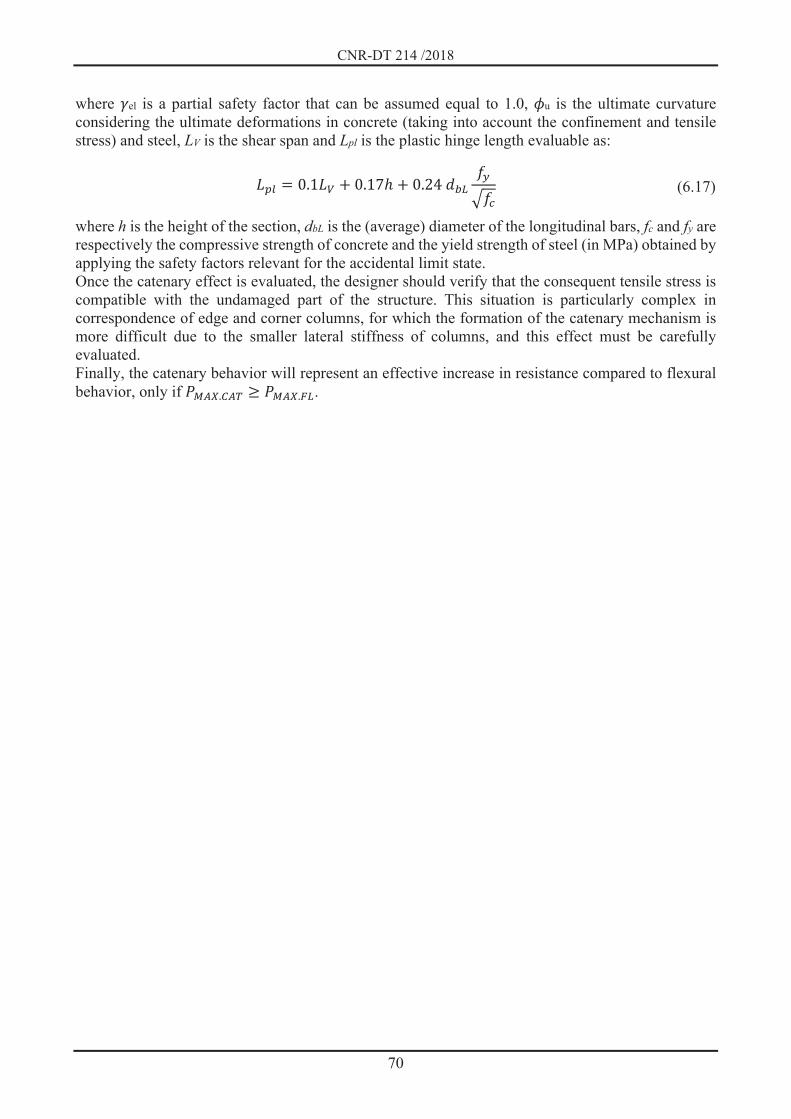
CNR-DT 214 /2018
70
where el is a partial safety factor that can be assumed equal to 1.0, u is the ultimate curvature considering the ultimate deformations in concrete (taking into account the confinement and tensile stress) and steel, LV is the shear span and Lpl is the plastic hinge length evaluable as:
where h is the height of the section, dbL is the (average) diameter of the longitudinal bars, fc and fy are respectively the compressive strength of concrete and the yield strength of steel (in MPa) obtained by applying the safety factors relevant for the accidental limit state. Once the catenary effect is evaluated, the designer should verify that the consequent tensile stress is compatible with the undamaged part of the structure. This situation is particularly complex in correspondence of edge and corner columns, for which the formation of the catenary mechanism is more difficult due to the smaller lateral stiffness of columns, and this effect must be carefully evaluated. Finally, the catenary behavior will represent an effective increase in resistance compared to flexural behavior, only if . . .
0.1 0.17 0.24 (6.17)

CNR-DT 214 /2018
71
6.3 REINFORCED CONCRETE PRECAST CONSTRUCTIONS
6.3.1 Preface In precast structures, structural and non structural elements are realized by industrial processes and in situ assemblages. Often structures are completed in situ through ordinary concrete castings with integration of steel bars and nets in specific regions. The evolution of precast process of reinforced concrete (RC) elements followed different approaches in different countries. In Italy and most of the Mediterranean countries, isostatic structural schemes are usually adopted, with mechanical connections between monolithic elements, whereas in US and other countries typically elements are precast only partially and then completed in situ with additional steel reinforcement and concrete. Due to the evolution of the prefabrication technology and of quality of materials, more complex structural schemes were proposed in the last decades, in order to realize large span structures. An inventory of the most common structural schemes is given in Reluis (2008), and some of them are summarized in Figure 6-14. Structures differ for the geometry of beam shapes, as well as of precast elements used for roof and slab structures. The latter are typically simply-supported on beams, and often integrated with realization of a steel reinforced supplementary concrete layer, in order to connect the slab elements, so providing in-plane stiffness and strength. In precast structures with isostatic schemes, the lack of structural redundancy clearly represents a limit to the structural robustness. Hence, connections between elements play a fundamental role in order to allow the structure to limit potential damages in the case of accidental and/or extreme events. For this reason, precast structures not designed with seismic criteria and without mechanical connections between elements are particularly vulnerable in the case of seismic actions. Nevertheless, as shown in Section 6.3.2 potential robustness problems in precast structures are not only related to the behavior in the case of horizontal actions. Due to the large stresses in connections, their transmission to the RC elements and compression stresses at the supports between structural elements (especially beam – column corbel connections), a particular care must be dedicated to the details concerning the assembly phases, as well as to the transmission of localized stresses. In isostatic precast structures, especially when multistory, an adequate level of robustness can be attained improving the connections between structural elements (see Section 6.3.3). On the contrary, for very large and single-floor precast structures, typical of industrial areas, this goal is difficult to be reached, and a partition of the building is often preferred, by reducing the connections at the roof elements level, in order to avoid a collapse due to an accidental event causing a disproportional collapse involving a large portion of the construction. An useful reference concerning possible approaches for design of precast structures considering robustness issues is the fib bulletin 63 (fib, 2012). A recent state of the art of documents available in literature for the assessment of the robustness of precast structures has been presented by Ravasini at al. (2020).

CNR-DT 214 /2018
72
a) b)
c) d)
e) f)
Figure 6-14 – Main typologies of precast structures in Italy (from Reluis 2008): a) Double slope beams; b) Planar roof structures; c) Shed structures; d) Truss structures; e) Boomerang beams; f)
multistory structures with cantilever columns.
6.3.2 Collapses in precast structures Buildings realized with precast structures are inherently sensitive to possible progressive collapses. A famous progressive and disproportional collapse occurred in a 22-floor apartment building in London, in 1968. The building had a precast panel structure, and a partial collapse occurred due to an explosion caused by a gas leak in an apartment located in the corner of the building, at 18th floor, causing the expulsion of two panels and the consequent collapse of the panel structure of the 4 upper floors (Figure 6-15). The impact then caused the collapse of almost all the walls and slabs located below the apartment affected by the explosion.

CNR-DT 214 /2018
73
The event underlined the importance of avoiding that a localized damage could cause a progressive collapse, and the need of provide for alternative load paths in the case of accidental or extreme events, so establishing the basis of structural robustness design as it is conceived today.
Figure 6-15 – Progressive collapse of a corner portion of a building realized with precast panels
(Ronan Point, East London) (from https://en.wikipedia.org/wiki/Ronan_Point) More recently, the earthquake which struck the Emilia region in Italy in 2012 clearly confirmed that the traditional RC precast systems adopted for the realization of industrial and commercial buildings, with isostatic elements and cantilever columns, can be particularly vulnerable in the absence of adequate mechanical connections between elements (Figure 6-16). Even though analogous collapses also occurred recently in other countries (Arsland et al., 2006; Ghosh e Cleland, 2012) and in Italy due to the L’Aquila earthquake sequences (Toniolo and Colombo, 2012), the gravity and the extension of collapses in Emilia were unprecedented (Liberatore et al., 2013; Magliulo et al., 2014; Minghini et al, 2016; Ercolino et al., 2016; Savoia et al., 2017; Bovo and Savoia, 2018). In the absence of horizontal actions due to earthquakes, until a few years ago the design criteria for precast structures considered the possibility of assembly the roof elements (roof elements, main and secondary beams, other non structural roof elements) only by means of dry supports or, in the case of beams with longer span, by interposition of neoprene supports (Magliulo et al., 2011). This construction system, very common because it allows very short construction times, turned out to be very vulnerable in the presence of seismic actions not considered in the design stages of the construction. The main collapse modes of isostatic precast structures, documented in some surveys and technical reports of Reluis research groups and in the Reluis document “Guidelines for local and global interventions on single-story industrial buildings not designed with seismic criteria” (2012), can be classified as follows:
- loss of support of roof elements from principal beams; - loss of support of principal beams from columns; - lateral instability of high beams without adequate structural retention elements; - fall of RC cladding panels due to connection failure; - structural damages due to stability losses of their contents (scaffoldings, etc).

CNR-DT 214 /2018
74
In many cases, the following factors contributed to increase the effects of damages, up to the collapses of entire portions of the buildings:
- the interaction with irregular infill masonry panels; - the failure of central columns with formation of plastic hinges at the column bases; - the lack of a adequate stiffness at the roof level allowing to distribute the seismic actions at
the elements with higher strength; - the rotation of foundations, especially in the case of pocket foundations not anchored at the
in-situ cast foundations. During the seismic strokes in Emilia, several partial collapses were caused by the loss of support between precast elements. In several cases, structural discontinuities and irregularities were the cause of inhomogeneous distributions of forces at the roof level, causing localized collapses (see Figure 6-16a, b). Among the possible irregularities, the in-plane stiffness of masonry infill panels played an important role in several collapses, especially when they were interrupted by strip windows just below the main beams. The very different stiffness of facade columns due to the interaction with the infill panels, caused an irregular distribution of the seismic forces between elements, acting on few columns only, with consequent shear forces at the support levels much greater than those admitted by the friction coefficients (Figure 6-17, Figure 6-18). In other cases, the lateral overturning of high beams, lacking an adequate constraint being the upper forks not present or not adequately steel reinforced, was an important reason of extended collapses (see Figure 6-19a). This aspect was very relevant in the case of shed beams (see Figure 6-19b), due to the significant vertical distance between the precast shed centroid and the support of the beam over the column. Of course, in the case of large shear forces due to the seismic actions, the only presence of a connection between precast elements is not sufficient to give the necessary redundancy to avoid the collapse, of the connection is not adequately designed for the seismic action (see Section 6.3.3) (Figure 6-20a, b).
a) b)
Figure 6-16 – Collapses of precast roof elements often occurred in 2012 Emilia earthquake where irregularities in the building structure were present: a) collapse of roof elements due to plan
irregularities; b) collapse of a portion of a two-floor prefabricated building (left) and of lateral spans of another building due to the interaction with masonry infills (right)

CNR-DT 214 /2018
75
Figure 6-17 – Collapses due to the loss of support of main beams from the column corbel
Figure 6-18 – Scheme of distribution of seismic horizontal forces in the presence of masonry infill panels at the building extremities interacting with the precast structure (from Savoia et al., 2017)
a) b) Figure 6-19 – Lateral overturning of high beams with insufficient lateral constraints; a) lateral over-turning of plane roof beams with collapse of the upper fork of the columns; b) collapse due to lat-
eral overturning of shed beams

CNR-DT 214 /2018
76
a) b) Figure 6-20 – Failure of mechanical connections not adequately designed: a) Failure of the extrem-ity of a main beam with fracture of the concrete cover insufficient to transfer the shear force trans-mitted by the mechanical connection on the top of the column; b) Collapse due to the yielding of
bars used for to realize the beam – column connection Finally, also the external concrete cladding panels, anchored with mechanical devices along the column heights, can be very vulnerable to seismic actions. In this case, the use of connections not designed to allow the large displacements occurring in the plane of the panels due to the high flexibility of the main structure (Figure 6-21d), but connected with very rigid and weak mechanical devices (Figure 6-21c), caused the failure of several cladding concrete panels (Figure 6-21a, b) (To-niolo and Colombo, 2012; Bournas et al., 2013).
a) b)
c) d)

CNR-DT 214 /2018
77
Figure 6-21 – (a, b) Failure of cladding concrete panels due to connection failure; c) detail of a con-nection after failure; d) scheme indicating the relative displacements and consequent forces at the
level of panel connections due to the large deformability of columns of the main structure The absence of adequate connections between structural elements can be the cause of significant collapses also in the absence of seismic actions. As an example, Figure 6-22a, b shown two collapses, the first of a roof structure with RC truss beams, due to the weight of snow, and the second of a cladding panel hit by a forklift during an erroneous operation. Several collapses occurred during the construction assembly operation of precast structures designed to be completed with steel reinforcements and in-situ cast concrete. Most of them occurred in the transition phases before the realization of connections between the various components, of connections to the shear wall designed to carry the horizontal forces of the final construction and to the foundation structures (see for example Figure 6-23). In order to reduce the construction times, only provisional connections are provided during the assembly, and the completion concrete casts are realized all together at the end of the assembly stage. Hence, a fault during the assembly stages can cause a progressive and disproportionate collapse of the whole structure.
a) b)
Figure 6-22 – Collapses due to (non seismic) accidental actions: a) collapse due to snow weight which caused high compression stresses and consequent failure of the small dry support of one RC
concrete truss beam over the column; b) fall of a RC cladding panel hit by the forks of a mechanical lift during an erroneous operation
6.3.3 Criteria to improve the robustness Precast structures can adopt very different structural schemes, and then very different can be the robustness issues, as described in Section 6.3.2. Isostatic structural schemes and solutions for multi-story buildings, where the final structure is completed with steel reinforcements and cast in-situ concrete to realize a final statically redundant scheme, can have very different characteristics as far as the structural robustness is concerned. In the following, the main criteria to be followed in order to avoid the occurrence of unexpected and sudden collapses are described with reference to the main structural schemes.
6.3.3.1 Precast systems with isostatic scheme The robustness against accidental and extreme actions (excluding the seismic action) of precast structures with isostatic scheme, especially with single-floor and large spans typical of industrial buildings, can be based on the compartmentalization principle, because it is not possible usually to consider alternative loading paths due to the limited structural redundancy. Seismic actions, on the

CNR-DT 214 /2018
78
contrary, involve the whole structure, and the robustness strongly depends on the connections between the structural elements.
a)
b)
Figure 6-23 – Progressive and disproportionate collapse of precast structures during construction: a) in Miami (from www.osha.gov/doc/engineering/2013_r_02.html); b) in Atlantic City (from
https://failures.wikispaces.com/Tropacana+Casino+Parking+Garage) For connections between horizontal elements (roof/slab elements – beams connections) and between horizontal and vertical elements (beam – column connections), the evaluation of the forces at the connection level can be estimated with a great uncertainty, because they depend significantly on the in-plane deformability of the roof/slabs, and hence on the deformability of the connections themselves, but also on the interaction with structural and non structural walls, office partitions, etc. See for example the case reported in Figure 6-18. From the point of view of numerical modelling, the presence of hundreds of local vibration modes makes the estimate of internal forces via dynamic modal analysis sometimes difficult to be interpreted by the engineer. Moreover, the action on beam – floor connection strongly depends on the static scheme of the connection itself, which can be isostatic or hyperstatic according to Figure 6-24a. Figure 6-24b shows, through an example, that the action on the connections strongly depends on the connection stiffness, which is difficult to quantify with accuracy (e.g. different Standards give different expressions for dowel stiffness). Limit cases for estimating the actions on connections are then suggested, even if their use can give too conservative estimates in some cases.

CNR-DT 214 /2018
79
Figure 6-24 - Static scheme of beam –floor connection (Belletti et al., 2014); example of estimate of
shear in beam – floor connections depending on the stiffness of the dowels. In beam – floor connections, an excessive stiffness could cause a stress concentration in some elements for the reasons previously discussed. In these cases, connections allowing a relative movement between the elements would be preferable, allowing a force redistribution at the roof / floor level. That movement must anyway be smaller than that which could possibly cause the loss of support of the precast element. Some examples of connections at the roof level allowing for a movement up to a maximum designed value are reported in Figure 6-25.
a)
b) Figure 6-25 – Beam – floor connections with deformability control: a) connection with a slotted hole (from Reluis 2012); b) connection allowing a maximum displacement through yielding: a
strengthening intervention of an existing structure and an experimental test (from Ligabue et al., 2014)
Iperstatic Isostatic
Isostatic Iperstatic

CNR-DT 214 /2018
80
Due to their intrinsic fragility and the difficulties on the accurate estimate of actions involved, connections must be designed according to a strength hierarchy criterion, with connection strength greater than strength of elements to be connected. This criterion is particularly important in the case of beam – column connections. It must be underlined that the connection is the entire system constituted by the connection itself (typically a metallic folded element) and the portions of structural elements connected. In particular, in the case of seismic actions the concrete strength in traction can be easily overcome and a proper steel reinforcement must be considered around the steel dowels or anchorages. Figure 6-26 shows an example of application of the beam – roof element connection where the strength of various components have been calculated according to Safecast Guidelines (Safecast, 2012). Note that a ductile failure can be attained only if the strength of the metallic elements of the connection is smaller than the local strength of concrete in the region close to the connection.
Figure 6-26- Static scheme of a beam – roof element connection (from Belletti et al., 2014)
Due to the high uncertainty in the evaluation of actions on the connection, in main connections (e.g. beam – column connections) it is unsafe to adsorb the action through the only traction strength of the concrete, but a steel reinforcement able to carry the entire force required by the connection is strongly suggested. In the case of beam – column connections, the strength hierarchy would require to calculate the possible maximum force acting at the upper connection level by considering the action which yields the steel bars at the column base section. Moreover, in a new construction the connection should be designed in order to limit the possible displacement of the beam over the support, because an excessive movement could cause a strong damage at the roof level. A similar problem is constituted by the connections of cladding panels to the RC columns. In this case, the connections of the panels should allow the free deformation of the main structure (see Figure 6-21d). If this movement is limited by the interaction with cladding panels, the deformation of the structure under a seismic action would cause forces which cannot be sustained by the connections, which will certainly fail (in the case of rigid connections, the panels would act as shear walls for the structure).
6.3.3.2 Precast systems with structural redundancy In several countries, as in Northern Europe and US, the precast industry mainly consider structural schemes where the precast elements are first assembled and subsequently integrated and connected by means of additional steel reinforcements and concrete casts in order to realize a final structure which is, at the end of the construction, hyperstatic and analogous to the classical in-situ cast frame structures. This system is for instance adopted to realize buildings with a large number of floors.

CNR-DT 214 /2018
81
The behavior of these structures under accidental actions is similar to that of traditional RC structures and, with adequate provisions, similar levels of structural robustness can be attained. Among the indirect methods to improve the robustness, the most common solution is the realization of steel tie reinforcements at all the floor levels (see Figure 6-27), roof level included, as well as in the vertical direction. Tie reinforcements should connect all the columns and shear walls. They can be steel bars or steel profiles, or even RC beams, whose steel reinforcements must be continuous and designed for the actions calculated. The tie reinforcements at the level of the floors can be internal (in longitudinal or transverse directions with respect to the floor element direction) or along the perimeter of the building (in this case, at a distance not greater than 1,2 m from the building side). In all the cases, particular attention must be devoted to the construction details, for instance to those designed to assure the tie continuity in the connections with the columns. Moreover, vertical ties must be designed, which will provide alternate loading paths (through suspension systems) in the case of strong damages to one or more columns. Some indications to design the tie reinforcements in precast structures are reported in Table 6-2.
Figure 6-27 – Tie reinforcements at each floor of a multistory precast structures (from fib, 2012)
Table 6-2 – Some rule for the design of tie reinforcements in precast structures with frame scheme
(from EN 1991-1-7)
Tie reinforcement Action for the tie reinforcement design
Internal ties T = max (0.8 (gk + qk) s l ; 75 kN )
Perimetral ties T = max (0.4 (gk + qk) s l ; 75 kN )
Vertical ties All the columns must be connected with continuity from foundation to the roof level;
Columns and walls must sustain a traction force due to the accidental event equal to the greatest value of reaction to the column (of wall) due to permanent and variable actions.
s = distance between tie reinforcements; l = tie length; = combination factor related to the action effects (accidental combination)
In the cast of slab realized with precast elements, if the accidental action causes the loss of a column, the membrane effect is usually less efficient with respect to the case of traditional in-situ cast slabs.

CNR-DT 214 /2018
82
The additional concrete cast layer, which includes the additional steel reinforcement, can be detached from the panels, and in this case the membrane effect is completely lost due to the discontinuity of the panels (see Figure 6-28). The lack of an effective membrane effect at the slab level can cause very significant damages in the case of a sudden loss of a column due to accidental action (see Figure 6-29). Solutions which improve the strength of the corner zone can be adopted, using vertical bracing systems or other suitable systems (see Figure 6-30).
Figure 6-28 – Structural behavior of a precast frame structure after the loss of an internal column
(from fib, 2012)
Figure 6-29 – Collapse after a corner column loss (from fib, 2012)

CNR-DT 214 /2018
83
Figure 6-30 – Possible solutions to improve the strength of the corner zone in buildings with precast
panels to realize the floor structure (from fib, 2012)
6.3.4 Structures with load bearing precast walls In the case of precast systems where the vertical walls are load bearing elements, the criteria to prevent progressive/disproportionate collapses are analogous to those of frame systems. By designing tie reinforcements, it is possible to not require that, in the case of accidental/extreme actions, the strength of panel-to-panel connections be the critical element. Moreover, the collapse due to the sudden loss of corner elements can be less critical with respect to frame structures because, if vertical tie reinforcements are used, the in-plane stiffness of the panels above the damaged zone can be sufficient and more complex solutions such those indicated in Figure 6-30 can be not necessary

CNR-DT 214 /2018
84
6.4 STEEL CONSTRUCTIONS
6.4.1 Preface Steel constructions are lighter and more deformable than reinforced concrete (RC) structures. However, they can offer high resistance against disproportionate collapse, taking care of construction details (e.g. connections, braces to restrain the members against buckling, etc.). In fact, it is possible to guarantee high ductility and redundancy by inhibiting the activation of brittle mechanisms. The detailed rules usually adopted in the seismic design of new steel structures (e.g. prequalified beam-to-column joints, full strength connections, full penetration welds, etc.) are valid solutions in many cases of accidental action. However, in the case of the loss of a column due to accidental actions (for example an explosion), the structure and the internal force regime distribution are strongly modified (Levy and Salvadori, 1997). Therefore, the detailing rules should be specialized to ensure the activation of resistant mechanisms that can be developed when the structure assumes a varied configuration, for instance the catenary effect in beams. Finally, the general goal of avoiding the activation of brittle mechanisms can be achieved by using an analogous approach to the hierarchy of the resistances as adopted in the seismic design.
6.4.2 Examples of collapses of steel constructions Several examples of steel construction collapse due to accidental actions can be found in the literature. Hereinafter, a brief overview of the most representative cases is summarized by distinguishing two types of collapse: 1) global collapse of the structure; 2) severe damage without global collapse
6.4.2.1 Global collapse The first example is the case of the Ambiance Plaza in Bridgeport, Connecticut (USA). This structure was designed for a 16-story residential building, which collapsed in April 1987 during the construction phases (see Figure 6-31). The building was conceived with post-tensioned pre-stressed concrete slabs. These elements were prefabricated aside the building and then mounted on a steel frame structure (Kokot and Solomos, 2011). The global collapse occurred after completing one of the laying operations of a portion of the floor. Heger, (2006) highlighted some structural deficiencies that could have been responsible for the collapse. Among these the most important are the (1) improper positioning of the post-tensioning cables of the floors in the areas adjacent to the openings of the elevator shaft; (2) inadequate beam-to-column connections (see Figure 6-32) to guarantee the stability of the frame.
Figure 6-31 – Collapse of the structure of the Ambiance Plaza (www.bfrl.nist.gov/861/861pubs/col-
lapse/workshop/7.L’AmbiancePlazaCaseStudy060913.pdf )

CNR-DT 214 /2018
85
Figure 6-32 – Details of beam-to-column joints of Ambiance Plaza (Ellingwood et al., 2007)
Another example of a global collapse is the Jackson Landing Skating Rink, which was an unheated indoor ice rink in Durham, New Hampshire (USA). The structure collapsed completely after a heavy snowstorm in 1996 (see Figure 6 32). The structure of the roof was made of cold-formed steel purlins with a Z and C shape. The purlins were bolted to the upper flange of the steel beams of the transverse frames. These beams had variable depth along the profile (see Figure 6-33). The collapse was caused by the failure of the base connection of a transverse frame that caused the opening of the frame, subsequently activating unstable lateral-torsional buckling of the roof beams and the progressive collapse of the entire structure. This type of collapse is particularly interesting, because it is a horizontal progression of collapse that is quite different from the more common vertical progression. This type of collapse draws attention to the need, in assessing the disproportionate collapse, to consider the ability of horizontal resistant systems to support extraordinary overloading or to provide redundancy to limit the horizontal progression of the collapse.
Figure 6-33 – Failure of the roofing of the Jackson Landing Skating Rink (Ellingwood et al., 2007)

CNR-DT 214 /2018
86
a) b)
Figure 6-34 – a) details of the structure of the Jackson Landing Skating Rink; b) collapse of the transverse frames (Ellingwood et al., 2007)
The most significant example of global collapse of steel buildings is the case of the Twin Towers of the World Trade Center (WTC) in New York (USA). Indeed, the terrorist attack that took place on 11 September 2001 was the event that mostly highlighted the importance of research on progressive and disproportionate collapse and the strength of the structures. On that day, 2996 people died and in addition to the Twin Towers of the WTC, eight large buildings in the lower part of Manhattan suffered a partial or total collapse, caused by the debris fallen from the towers, with a total of 2.8 million square meters of commercial offices decommissioned (FEMA, 2005). Figure 6-35 shows the structure of the twin towers, which is a frame with rigid perimeter joints with dense mesh and an internal core of RC. The square plan had sides of about 63 m and the steel decks were supported by truss girders.
a) b) c) Figure 6-35 – Structural details of the Twin Towers of the World Trade Center: a) plan showing che inner core and the truss girder supporting the deck, b) the perimetric frame of the towers, and c) the
plan and the transverse section of the roof truss (FEMA, 2002)

CNR-DT 214 /2018
87
On the morning of September 11, 2001, two airplanes were hijacked and hit the WTC's towers. At 8.46 am the first airplane crashed into the north wall of tower 1 (WTC 1). Sixteen minutes later, a second airplane collided with the south wall of the second tower (WTC 2). The impacts of the airplanes caused considerable damage to the towers and triggered a series of intense fires in the surrounding floors. About 56 minutes after the impact, WTC 2 collapsed. However, the collapse of WTC 1 occurred 1 hour and 43 minutes after the initial impact. Therefore, the sequence of events that led to the collapse of the two towers was similar but not identical (FEMA, 2002) Despite the localized massive damage that was observed following the impact with the aircraft (see Figure 6-36), WTC 1 remained standing immediately after the impact due to its ability to redistribute vertical loads. Indeed, the loads originally supported by the damaged external columns were transferred to the adjacent columns which were largely overdesigned, while the undamaged central columns supported the remaining load. It is interesting to note that the roof truss system played a considerable role in the redistribution of these loads, guaranteeing the possibility of activating alternative load paths between the internal core and the perimeter frame system. In addition to the direct impact damage, the fuel on board the aircraft caught fire when the plane was passing through the tower. This triggered a series of fires located in the floors directly affected by the impact of the airplane (i.e. between 92nd and 97th floor). With the spread of fires, the temperatures reached in some points 1000 °C, thus weakening the truss girders and the steel columns. In particular, the collapse of the floor truss girders due to the loss of resistance produced by excessive heating triggered the progressive collapse, pulling the perimetric columns inward.
a) b) Figure 6-36 – World Trade Center 1 a) Aircraft impact zone; b) damages to the perimeter columns
on the north wall of the tower (FEMA, 2002) Even WTC 2 remained standing immediately after the impact, since the loads initially supported by the damaged structural elements were redistributed among the surrounding elements thanks to the high redundancy of the perimetric frame system. The sequence and progression of the damage was very similar to that occurred in WTC 1. However, in this case the collapse progressed more rapidly. Also in this case, the fuel from the aircraft caused widespread fires at various levels around the impact zone between the 79th and 83rd floors (see Figure 6-37). The spread of fire and the increase in tem-peratures caused the failure of the decks, pulling the perimetric columns along the east wall inwards. As a result of this, at 9.59 in the morning, the section of the building above the impact zone tilted east, then south, and began its collapse.

CNR-DT 214 /2018
88
a) b) Figure 6-37 – World Trade Center 2: a) Aircraft impact zone; b) damages to the perimeter columns
on the south wall of the tower (FEMA, 2002) The reasons why WTC 2 collapsed in a shorter period than WTC 1 are complex and largely unknown. However, one can try to explain this difference by comparing the impact damage sustained by the two towers. These differences can be summarized as follows (FEMA, 2002; NIST, 2005): - In WTC 2, the plane hit the southern part of the tower in an eccentric way (about 7 m to the east), while WTC 1 was hit in the center of the north wall of the tower. - WTC 2 was hit with a greater angle of inclination than WTC 1 (almost horizontal angle of incidence) increasing the number of floors involved in the initial impact damage. - The impact zone for WTC 2 was approximately 20 floors lower than that of WTC 1. - The total area affected by the impact was estimated to be greater for WTC 2 due to the higher speed of the airplane that hit this tower was hit (870 km / h compared to 708 km / h).
6.4.2.2 Partial collapse The building at 130 Liberty Street in New York (USA), also known as "The Bankers Trust Building" or "Deutsche Bank" is an emblematic example of severe damage with partial collapse, but without global collapse. This building was built in the early 1970s and is located on south side of the former World Trade Center complex in Manhattan, New York. The building has a 40-story steel moment-frame structure. Following the attack on the Twin Towers (11 September 2001), the building was hit by the falling of debris produced by the collapse of the World Trade Center twin towers. As a consequence, the perimetric structures between the ninth and twenty-third floors of the building were destroyed. However, the collapse did not spread, and the building remained standing (see Figure 6-38). The analysis of the damage showed that the redundancy and the high rigidity and strength of the perimetric beams on the upper floors allowed the activation of a resistant Vierendeel beam type mechanism, thus inhibiting the propagation of collapse.

CNR-DT 214 /2018
89
a) b) Figure 6-38 – Partial collapse of the perimetric structure of the building at 130 Liberty Street (pic-
ture a) from Ellingwood et al., 2007, picture b) from FEMA Photo Library. https://www.fema.gov/media-library/search/4019#{"keywords":"4019"})
Another interesting case is the terrorist attack of the St Mary's Ax court in London in 1992. The court building ("Exchequer Court") was a modern steel building with composite steel-concrete floors and steel braced structure to resist wind actions. All beam-to-column joints were pinned with bolted flush end-plate connections. Following the explosion of a bomb due to a terrorist attack, the building was significantly damaged but did not collapse. Figure 6-39 shows the extent of the damage and the duc-tility of the steel columns. In this case, the ductility of the members and the presence of the bracings (which were not damaged) prevented the global collapse.
a) b) Figure 6-39 – Terrorist attack of the St Mary's Ax court, London 1992: a) damages in the composite steel-concrete slabs; b) plastic deformation and ductility of the columns at base floor (Moore 2002)
Among the various types of accidental actions, even fire can induce cases of global or partial collapse. An interesting case of partial collapse of steel structure due to fire actions is that of Tower "A" of the

CNR-DT 214 /2018
90
new court (also known as “New Palace of Justice”) in Naples. This 29-story building (total height equal to 109.20 m) had a dual structural system with a steel structure designed mainly to resist vertical loading and an internal RC core devoted to resist the horizontal actions. During the completion of the erection of the tower, on July 30, 1990, a large arson attack considerably damaged the structure. In particular, the building's EAST wing suffered a partial collapse. Furthermore, due to severe damage, the remaining part of the steel structure was demolished while the RC components were retrofitted. The collapse of the steel structure was due to the lack of adequate fire protection, as well as to the conception of the connections and torsional restraints of the beams. In fact, the connections between the floor beams were not designed to withstand significant bending actions as well as any catenary type actions. Furthermore, the lack of adequate torsional restraints led to the premature failure of the beams. Subsequently, tower “A” was redesigned and rebuilt, see Figure 6-40. The new structural project was drawn up with the spirit of keeping the structural schemes unchanged in order not to modify both the architectural and the plant components. However, the joints of the steel structure were redesigned to transfer the bending, so as to guarantee greater redundancy and a dual frame behavior with the RC core.
a) b) Figure 6-40 – Steel structure of the Tower “A” the new court in Naples: reconstruction after the ar-
son attack (http://www.ai-studio.it/?project=1003)
6.4.3 Design criteria and intervention approaches for steel constructions To arrest the propagation of the collapse caused by extreme and / or accidental events, both global and local interventions may be necessary (see Chapters 4, 5 and 6). In the case of steel constructions, local interventions are mainly intended for the connections and the members. In general, in the case of collapse induced by loss of a column, in accordance with the approach based on the Consequence Classes of EN 1991-1-7, structures with low susceptibility to collapse do not require any additional detail rule. In fact, it can be considered that, in the case of loss of one or more columns, the structure has a sufficient reserve of ductility. For structural types with medium susceptibility to collapse, it is necessary to adopt local detailing rules in order to improve robustness. Finally, for vulnerable structural typologies, in line with the recommended strategies for buildings in Consequence Class 2b (i.e. at high risk), both local and global interventions are necessary. For the latter, it is necessary to perform structural analyses that take into account the alternative load path to ensure that the progressive collapse is stopped. For structural analyses, see paragraph 6.1.1 of this document.
6.4.3.1 Requirements for members During a progressive collapse, damage and plastic deformations can occur anywhere in the structure. Therefore, in order to ensure the formation of plastic hinges with adequate rotation capacity without

CNR-DT 214 /2018
91
reducing the resistance of the members, it is appropriate to design them by using class 1 sections in accordance with the classification of EN1993-1. Indeed, beams with sections of class 2, 3 or 4 are susceptible to local instability phenomena that limit their rotational capacity and flexural resistance (see Figure 6-41).
a) b) Figure 6-41 – Flexural response of steel beams under large deformations: a) with and b) without lo-
cal buckling (Wong, 2009) However, in order to guarantee the rotational capacity of class 1 sections, it is necessary to design torsional restraints against lateral-torsional buckling of the members in the presence of plastic hinges and the bending moment diagram similar to the collapse scenario examined. Indeed, the beams of the deck are generally connected to the floor, which constrains against lateral instability the upper flange that is generally compressed. In the event of a column loss, the moment diagram may change its sign and the lower flange of the beam profile may undergo compression deformations. In the absence of suitable bracing systems, the beam is not restrained against buckling, thus being unable to provide the ductility of the steel profile. The spacing and resistance of the torsional restraints can be determined in accordance with EN 1993:1-1 (CEN, 2005).
6.4.3.2 General requirements for beam-to-column and beam-to-beam joints The connections should be designed to ensure rotations greater than those estimated by the structural analysis under the action of column loss. In order to reduce the rotation demand under the column loss, the beam-to-column and beam-to-beam joints may be designed as semi-rigid, based on the classification of EN 1993: 1-8 (CEN, 2005). In order to avoid brittle failure, the minimum resistance of the connections should be associated to a collapse mode of ductile type (e.g., in the case of shear bolted connections, the bearing resistance should be lower than the shear resistance of the bolts; in the case of welded connections, the yield strength of the connected elements should be lower than the resistance of the welds). In the case of bolted end-plate connections, the full penetration welds should be used between the end of the beam and the end-plate. These welds should be executed in the factory and properly controlled. The filler material of the welds should have greater strength and resilience than the materials of the connected elements to prevent any brittle failure of the welds. In order to avoid severe damage to the joints, the latter should be designed to guarantee flexural resistance greater than the strength of the connected beams considering the activation of the catenary action and the corresponding increase of shear force.

CNR-DT 214 /2018
92
In analogy to the seismic design of full strength joints (D’Aniello et al., 2017), the design moment acting on the joint Mj,Ed can be estimated as follows:
where MB,Rd is the plastic moment of the connected beam; VB,Ed is the shear force due to the sum of the shear force corresponding to the formation of plastic hinges at both ends of the beam and the shear force associated to the gravity loads; sh is the distance between the plastic hinge and the axis of the joint; ov is the material overstrength factor accounting for the variability of yield stress (the values of
ov are provided by National codes); sh is the coefficient accounting for the hardening of the beam and may be assumed as follows:
being fy and fu the yield and ultimate stress of the material of the beam. In order to guarantee the full strength for catenary action, the tension resistance of the active bolt rows in the tension ( Ft,Rd), namely the bolt rows located in the half depth of the bolted connection, should be designed to resist the full axial plastic resistance of the beam (Npl,Rd,Beam), in such a way
Ft,Rd/Npl,Rd,Beam 1. This simplified criterion allows designing full strength connections in the case of column loss scenarios (Tartaglia et al., 2018). If Ft,Rd/Npl,Rd,Beam < 1, the connection will develop plastic deformations and additional criteria are necessary to guarantee adequate ductility. In order to enhance the performances (i.e., strength and ductility) of end-plate bolted connections, both the thickness of the end-plate and bolt diameter should be designed in order to activate their corresponding resistance but avoiding the failure mode type 3 per bolt row, which typically corresponds to a brittle failure mode in T-Stub connections. On the basis of this consideration, the thickness of the end-plate may be selected within the range of the values that guarantee the activation of a failure mode type 2 once given the bolt diameter (which is generally designed to resist the shear forces due to gravity loads). The limit values of the thickness of end-plate (i.e. , and , , respectively) may be derived considering the average properties of the materials as shown by Cassiano et al., (2017) as follows:
where d is the bolt diameter; fub is the ultimate strength of the bolt material; fy is the yield strength of the material of the end-plate; ov is the material overstrength factor of the end-plate; sh is the hardening factor of the end-plate; is the coefficient to be used to calculate the effective width of T-Stub per bolt row in accordance with EN 1993:1-8 (CEN, 2005); M0 and M2 are the partial safety factors of the materials of end-plate and bolts, respectively. In order to improve the resistance in the case of a catenary action, it is appropriate to introduce one or more internal bolt rows aligned with the centroid of the beam section. The bolts for the additional rows should have the same steel grade or higher than that adopted in other bolt rows of the same connection. The nominal diameter of the additional bolts must not be smaller than the maximum
, , , (6.18)
2 (6.19)
, 0.40 0.26 , : (6.20)
, 0.9 1.43 1.15 0.8 (6.21)

CNR-DT 214 /2018
93
diameter of the other bolts in the same connection and, if possible, must be greater, in order to increase the resistance against the actions induced by the loss of the column. The type of bolts to be used in the additional rows should have a tensile failure mode characterized by the tension tearing of the bolt shank (for example bolts of type SB and HR) to avoid sudden drops in resistance as the imposed rotations increase. Therefore, it is preferable to avoid bolt assemblies characterized by nut stripping (e.g. HV type bolts), unless it can be demonstrated that the elements of the structure affected by the accidental action (e.g. the beams of the moment-resistant frames) suffice to arrest the progressive collapse for all the column loss scenarios. In the case of a loss of column along the perimeter of the building, the connections of the perimetric beams (see Figure 6-42) must be designed to withstand a torsional moment at least equal to 20% of the plastic torsional strength of the connected beam. In fact, in the case of a loss of column (as shown in Figure 6-42) in addition to the increase of bending moment and shear force these connections are subjected to high twisting moments which can lead to premature crisis of bolts and / or welds.
a) b) c) d)
Figure 6-42 – a) torsional effects of the connections of transverse beams; b) in the case of column loss in the perimeter; c) internal column; d) example of damage distribution (Tartaglia et al., 2018)
In the case of welded connections, full penetration welds should be designed between the end of the beam and the column. Full penetration welds should be executed in the factory and properly controlled. As for the bolted connections, the filler material of the welds should have greater strength and resilience than the materials of the connected elements to avoid any brittle failure of the welds. In order to improve the flexural response of the welded joint, as well as its resistance under catenary action, the use of stiffeners and / or ribs is recommended. For the structural typologies in which the main structural elements remain in the elastic field under column loss (i.e. with DIF tending to 2), the use of stiffened joints contributes at improving the overall response. In the case of bracing connections and / or tie rods, the strength of the connection must be greater than the ultimate resistance of the connected member, the latter evaluated considering the average strength of the material. In addition, the yield strength of the perforated parts of these types of connection should be greater than the plastic strength of the connected members in order to avoid brittle failure.
6.4.3.3 General requirements for column-to-column connections The column-to-column connections should be located approximately at half the floor height and, in any case, not less than 1200 mm above the beam-to-column joint. Furthermore, in order to ensure the formation of an alternative path of the loads following the loss of a column on the lower floor, these connections must be designed to withstand the following combined actions:
- tensile force NEd equal in modulus to the axial force due to vertical loads in the design combination at the ultimate limit state;
- shear forces evaluated alternately in the two main directions of the column section and calculated as follows:

CNR-DT 214 /2018
94
where: Mc,pl,Rd(NEd) is the design bending resistance of the column in the examined axis, to be
calculated considering the interaction with the axial force NEd; h is the interstory height, to be calculated as the net distance between the two consecutive
stories, namely without the half depth of beam at both upper and lower story.
2 c,pl.Rd Edc,Ed M NV h (6.22)

CNR-DT 214 /2018
95
6.5 TIMBER CONSTRUCTIONS
6.5.1 Preface Timber structures, similarly to steel ones, are lighter and more flexible than those realized with reinforced concrete (RC) and are characterized by a lower degree of redundancy. However, they can guarantee adequate structural robustness through a proper design of construction details. It should be noted that the detail rules typically adopted in seismic design of timber structures (e.g. buildings, roofs, etc.) generally are not enough to ensure adequate robustness, making it necessary to adopt specific design and detail rules for the different structural typologies. Timber structures are characterized by a high strength-to-density ratio that reduces both dynamic inertial effects and the weight of elements that may collapse on the surviving structural elements (Hewson, 2016), reducing the probability of progressive collapse. However, similarly to steel constructions, the high strength-to-elastic modulus ratio of timber makes the structures sensitive to buckling phenomena, therefore it is essential to consider the second order effects in the damaged configuration when a direct design method is adopted. Timber structures can be catalogued accordingly to different criteria: by construction system, by static scheme or by type of structural elements. In the following, reference will be made to the subdivision by construction system/structural typology as reported also in the CNR-DT 206 R1/2018 “Istruzioni per la Progettazione, l’Esecuzione ed il Controllo delle Strutture di Legno”:
Wall systems - which can be further subdivided into: cross-laminated timber buildings (CLT or X-lam panels), “blockhaus”, buildings with light stiffened frames (also known as balloon frame or platform frame);
Heavy frame systems - Formed by assembly of beams and columns; Floors - which can be further subdivided into unidirectional (joist) or bidirectional (panel)
systems; Roof systems - which can be further subdivided into: truss structures, structures with one-
dimensional elements (beams, arches, etc.) and two-dimensional structures (CLT membranes).
Regardless of the structural typology, in order to achieve a behavior that satisfies the requirements of structural robustness, it is necessary to refer to the general rules given in Section 12 “Structural Robustness" of the aforementioned CNR-DT 206 R1/2018. In addition to the general requirements, structural robustness can also be achieved by adopting the capacity design criteria defined in CNR-DT 206 R1/2018 for seismic design, ensuring the development of ductile mechanisms and preventing the activation of brittle ones (e.g., failure of connection system and not of the connected timber element; activation of ductile failure modes of connectors). In the design of the construction details, particular attention shall also be paid to stresses perpendicular to the grain direction and to the effects of the dimensional variations induced by the hygrometric gradients of the wood which cause shrinkage cracks. Finally, it should be noted that timber structures are typically realized prefabricating all the elements; therefore, even if the production of the components is controlled and reliable, the assembly phase can lead to errors and variations that can significantly compromise the capacity of the structure to withstand extreme and/or accidental events.
6.5.2 Collapse of timber structures and strategies to ensure robustness Specific studies are available in the literature on failure causes and modes for timber structures, see for instance Blaß and Frese (2007), Frühwald et al. (2007) and Dietsch and Winter (2009), to which readers can refer for more details. In general, the bibliography deals mainly with studies relating long-

CNR-DT 214 /2018
96
span roof structures, while there are few specific studies on multi-story timber buildings since this building technology is still quite recent. The study carried out by Frühwald et al. (2007) refers to a sample of 127 buildings that reached the ultimate limit state in different ways, i.e., for different causes such as the failure of at least one structural element, a local failure, a local crushing or due to material degradation. The study shows that less than one-third of the examined cases shows a level of robustness that can be defined as “medium-to-high”, while in all other cases an inadequate level of robustness was found. With reference to the above-mentioned collapse modes, in the case of collapse of at least one structural element, 62% of the examined samples were found not to be robust. The main failure modes detected are: buckling (30%), bending failure (15%), tension failure perpendicular to the grain (11%), shear failure (9%), drying cracks (9%). The study also shows that the collapse occurred within 3 years from the construction for a third of the examined cases, while the collapse occurred during construction for 20% of the examined cases. In addition, the durability of the material often affected the structural strength. The main reasons of the collapse of timber structures can be classified as (Frühwald et al., 2007):
- Poor material and/or product mechanical properties (11%): Low material mechanical performances; Manufacturing errors at the production plant; Poor production methods.
- Building errors (27%). - Design errors (53%):
Errors in the prediction of the strengths; Errors in the prediction of the acting loads.
- Overloads respect to the actions provided by codes (4%). - Other reasons (5%).
Similar remarks are reported in the study conducted by Dietsch (2011), where a sample of 214 damaged timber buildings was examined. This study shows that 70% of design and maintenance errors determined a global collapse of the structure, while only 30% of them caused local failures. This data is confirmed by the previous study carried out by Ellingwood (1978) on the collapse of structures made with different building materials, which shows that about 45% of the collapses is due to design errors, 38% to errors during construction and 17% to those in maintenance. It is important to note that long-span roof-structure collapses are generally due to defects caused by systematic errors and thus distributed in the structure, rather than to randomly distributed local imperfections. For this reason, for widespread timber structures, it is often preferable to ensure robustness by compartmentation (Sorensen, 2011). Actually, the presence of defects due to systematic errors in several parts of the structure implies that the possibility of redistribution of loads (if there is structural redundancy) is detrimental to safety, because the consequent increase of stresses in the contiguous undamaged elements which are however affected by the same systematic defect, likely leads to a propagation of the failure (i.e. progressive collapse). On the contrary, in the case of multi-story timber buildings, the structural strength can be ensured also by using other design strategies, in particular by exploiting structural redundancy or alternative load paths. The analysis of the collapse of two long-span roof-structures, the Siemens Arena in Denmark (Figure 6-43) and the Bad Reichenhall ice-arena in Germany (Figure 6-44) shows that the failure was due to the presence of widespread defects. However, while in the first case the collapse of two lenticular trusses did not spread to the entire structure, thanks to the limited transversal distribution of the stresses offered by timber purlins, intentionally designed as weak elements, in the second case the stiff and strong timber purlins (that were part of the bracing system) caused the redistribution of the load to the adjacent elements.

CNR-DT 214 /2018
97
Figure 6-43 – Collapse of the timber roof of the Siemens Arena in Ballerup, Denmark (from COST
Action E55, 2010)
Figure 6-44 – Roof collapse of the Bad Reichenhall ice-arena in 2006 in Germany (from
https://www.cbsnews.com/pictures/germany-roof-collapse/18/) It is however important to highlight that, as observed in (COST Action E55, 2010), it is not correct to define wrong - or less suitable - the design approach based on the structural redundancy in timber structures in order to guarantee structural robustness. It is therefore fundamental that the design for robustness of timber structures is not carried out only against local damages, but also in the hypothesis of systematic damages, resulting for example from design errors and, consequently, globally spread in the structure.
6.5.3 Long-span roof structures The long-span roof structures (e.g., sports halls, swimming pools, arenas, theatres, conference halls, etc.) are generally built with statically determinate main elements (for example, lattice girder beams, glulam beams often with variable height, arches, etc.), which support a system of secondary structures often consisting of beams. The system of secondary beams can be realized as a set of simply-supported beams, continuous beams, or joined beams, or with a system of Gerber beams (Figure 6-45).
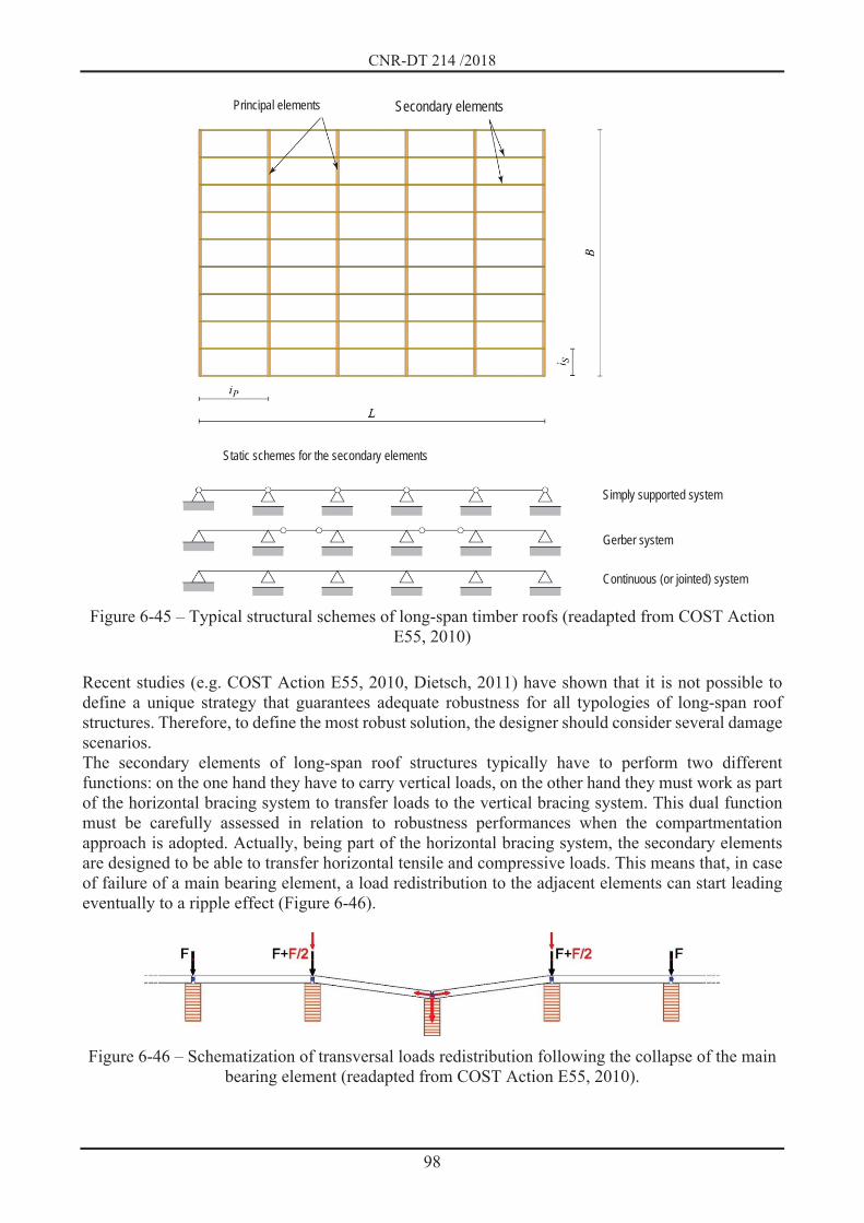
CNR-DT 214 /2018
98
Figure 6-45 – Typical structural schemes of long-span timber roofs (readapted from COST Action
E55, 2010) Recent studies (e.g. COST Action E55, 2010, Dietsch, 2011) have shown that it is not possible to define a unique strategy that guarantees adequate robustness for all typologies of long-span roof structures. Therefore, to define the most robust solution, the designer should consider several damage scenarios. The secondary elements of long-span roof structures typically have to perform two different functions: on the one hand they have to carry vertical loads, on the other hand they must work as part of the horizontal bracing system to transfer loads to the vertical bracing system. This dual function must be carefully assessed in relation to robustness performances when the compartmentation approach is adopted. Actually, being part of the horizontal bracing system, the secondary elements are designed to be able to transfer horizontal tensile and compressive loads. This means that, in case of failure of a main bearing element, a load redistribution to the adjacent elements can start leading eventually to a ripple effect (Figure 6-46).
Figure 6-46 – Schematization of transversal loads redistribution following the collapse of the main
bearing element (readapted from COST Action E55, 2010).
Principal elements Secondary elements
Simply supported system
Gerber system Continuous (or jointed) system
Static schemes for the secondary elements

CNR-DT 214 /2018
99
In order to achieve an adequate compartmentation able to reduce the risk of progressive and disproportionate collapse, it is possible to realize connections designed to allow the disconnection of the element in case of collapse of the main beam (Figure 6-47a). An alternative solution is represented by the transfer of compression-only horizontal loads through a unidirectional connection that allows the disconnection of the element (Figure 6-47b). As a different solution, the vertical load-bearing and the bracing functions can be assigned to two different structural systems. In this case, if the main beam collapses the load transfer to adjacent elements is prevented (Figure 6-47c). Finally, it is possi-ble to insert suitable elements that allow to resist to tensile force up to a fixed limit, beyond which they fail and the secondary beam may collapse without involving the principal beam. (Figure 6-47d).
Figure 6-47 – Examples of connections between primary and secondary beams that allow to realize
robust roofs accordingly to the compartmentation strategy (readapted from COST Action E55, 2010)
When timber panels (CLT panels or Glulam beams laid on their flat side) are adopted for the roof system, also fulfilling the role of bracing systems, it is necessary to carefully evaluate the interaction with the main structure. In fact, they can exert a membrane behavior that, even if it ensures a certain capacity of load redistribution, on the other hand prevents the compartmentalization.
6.5.4 Wall system In this section, some rules aimed at ensuring the robustness of structures with a solid timber wall system (CLT and blockbau systems) or with a framed wall structure (light frame walls) are reported. As a result of the localized damage, which may affect all or part of the vertical load bearing structural element depending on its dimension, it is essential to verify that:
1. the residual vertical elements are not subjected to buckling phenomena; 2. the connections and the structural elements are properly designed to guarantee a possible load
redistribution, even with static schemes not foreseen during the normal functioning of the
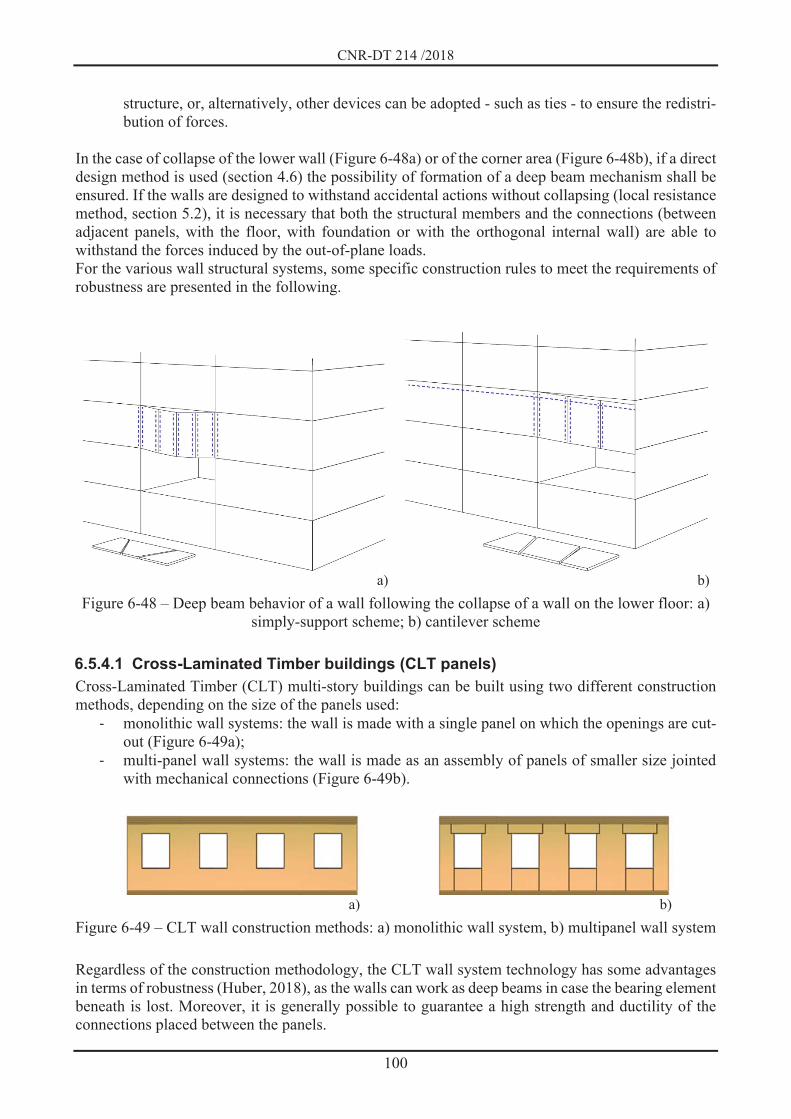
CNR-DT 214 /2018
100
structure, or, alternatively, other devices can be adopted - such as ties - to ensure the redistri-bution of forces.
In the case of collapse of the lower wall (Figure 6-48a) or of the corner area (Figure 6-48b), if a direct design method is used (section 4.6) the possibility of formation of a deep beam mechanism shall be ensured. If the walls are designed to withstand accidental actions without collapsing (local resistance method, section 5.2), it is necessary that both the structural members and the connections (between adjacent panels, with the floor, with foundation or with the orthogonal internal wall) are able to withstand the forces induced by the out-of-plane loads. For the various wall structural systems, some specific construction rules to meet the requirements of robustness are presented in the following.
a) b) Figure 6-48 – Deep beam behavior of a wall following the collapse of a wall on the lower floor: a)
simply-support scheme; b) cantilever scheme
6.5.4.1 Cross-Laminated Timber buildings (CLT panels) Cross-Laminated Timber (CLT) multi-story buildings can be built using two different construction methods, depending on the size of the panels used:
monolithic wall systems: the wall is made with a single panel on which the openings are cut-out (Figure 6-49a);
multi-panel wall systems: the wall is made as an assembly of panels of smaller size jointed with mechanical connections (Figure 6-49b).
a) b) Figure 6-49 – CLT wall construction methods: a) monolithic wall system, b) multipanel wall system Regardless of the construction methodology, the CLT wall system technology has some advantages in terms of robustness (Huber, 2018), as the walls can work as deep beams in case the bearing element beneath is lost. Moreover, it is generally possible to guarantee a high strength and ductility of the connections placed between the panels.

CNR-DT 214 /2018
101
On the other hand, it is worth noting that a CLT wall system usually has a larger weight than other types of timber constructions, therefore the corresponding dynamic effects and the weight of the elements involved in the collapse on the surviving structures are higher. In order to ensure a sufficient strength of the building after the collapse of a wall at a lower floor, an alternative load paths or resistant mechanisms must be identified (Figure 6-50). For example, in the case of walls with openings, the undamaged upper wall can be treated as a Vierendeel beam resistant mechanism.
Figure 6-50 – Variation of the load path following the loss of the wall on the ground floor
In the case of a Vierendeel beam resistant mechanism, section 9.2 provides, for some wall dimensions (different in length, number of openings and dimensions of the lintels), the minimum sizes of the different elements in order to ensure an adequate robustness to the wall system. The minimum sizes are defined with reference to monolithic wall panels, but they can also be extended to the case of jointed panels, if suitable connections between the individual sub-panels that compose the wall are designed. Actually, in the case of walls made as an assembly of several sub-panels (Figure 6-49b) - common in construction practice to reduce processing scraps and facilitate lifting of the panels themselves - the connections should restore bending and shear continuity between the elements to ensure an overall monolithic wall behavior (Figure 6-51).
a) b)
Figure 6-51 – Wall consisting of sub-panels assembly: a) wall geometry; b) details of the connec-tion systems
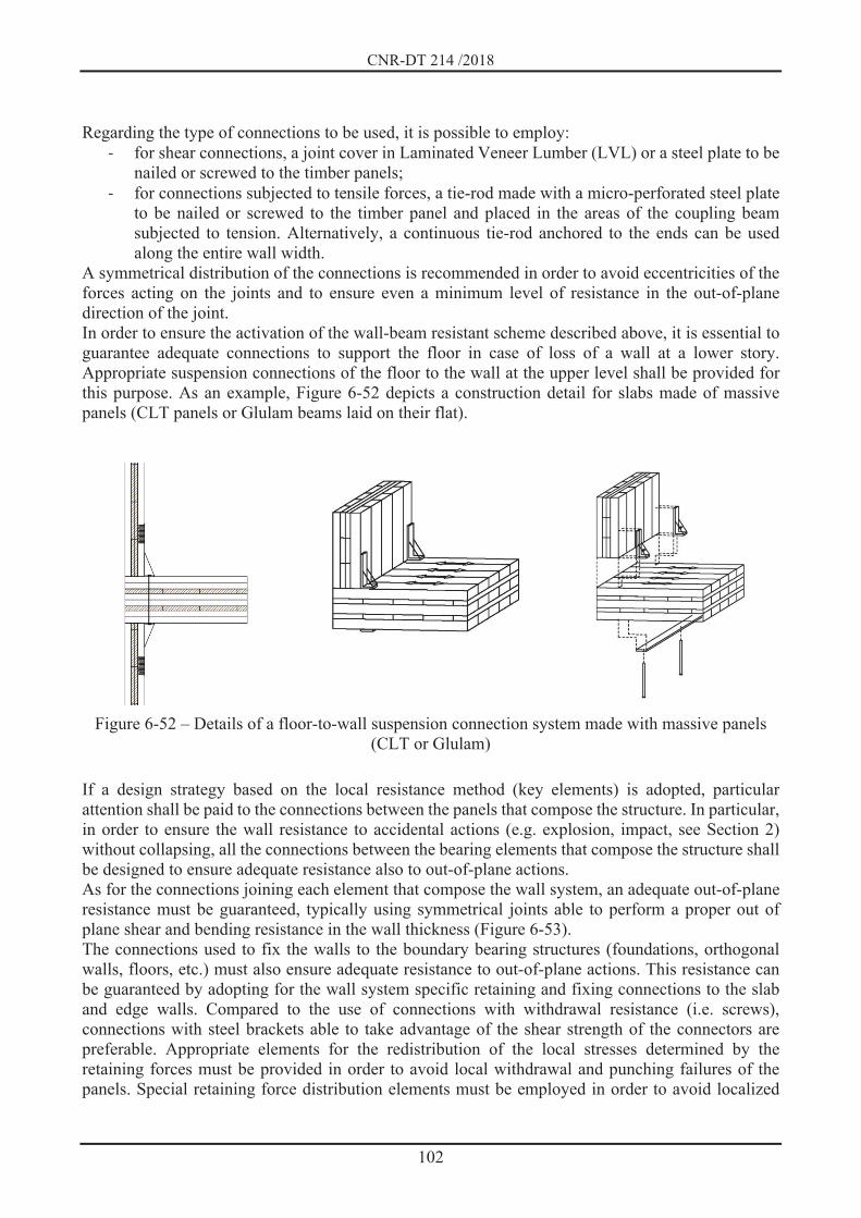
CNR-DT 214 /2018
102
Regarding the type of connections to be used, it is possible to employ:
for shear connections, a joint cover in Laminated Veneer Lumber (LVL) or a steel plate to be nailed or screwed to the timber panels;
for connections subjected to tensile forces, a tie-rod made with a micro-perforated steel plate to be nailed or screwed to the timber panel and placed in the areas of the coupling beam subjected to tension. Alternatively, a continuous tie-rod anchored to the ends can be used along the entire wall width.
A symmetrical distribution of the connections is recommended in order to avoid eccentricities of the forces acting on the joints and to ensure even a minimum level of resistance in the out-of-plane direction of the joint. In order to ensure the activation of the wall-beam resistant scheme described above, it is essential to guarantee adequate connections to support the floor in case of loss of a wall at a lower story. Appropriate suspension connections of the floor to the wall at the upper level shall be provided for this purpose. As an example, Figure 6-52 depicts a construction detail for slabs made of massive panels (CLT panels or Glulam beams laid on their flat).
Figure 6-52 – Details of a floor-to-wall suspension connection system made with massive panels (CLT or Glulam)
If a design strategy based on the local resistance method (key elements) is adopted, particular attention shall be paid to the connections between the panels that compose the structure. In particular, in order to ensure the wall resistance to accidental actions (e.g. explosion, impact, see Section 2) without collapsing, all the connections between the bearing elements that compose the structure shall be designed to ensure adequate resistance also to out-of-plane actions. As for the connections joining each element that compose the wall system, an adequate out-of-plane resistance must be guaranteed, typically using symmetrical joints able to perform a proper out of plane shear and bending resistance in the wall thickness (Figure 6-53). The connections used to fix the walls to the boundary bearing structures (foundations, orthogonal walls, floors, etc.) must also ensure adequate resistance to out-of-plane actions. This resistance can be guaranteed by adopting for the wall system specific retaining and fixing connections to the slab and edge walls. Compared to the use of connections with withdrawal resistance (i.e. screws), connections with steel brackets able to take advantage of the shear strength of the connectors are preferable. Appropriate elements for the redistribution of the local stresses determined by the retaining forces must be provided in order to avoid local withdrawal and punching failures of the panels. Special retaining force distribution elements must be employed in order to avoid localized

CNR-DT 214 /2018
103
tearing or punching of the panels. The used connection systems must be able to provide a bilateral constraint (Figure 6-54).
Figure 6-53 – An example of assembly joint between panels of the CLT wall system able to guaran-
tee an out-of-plane resistance in both directions
a) b) Figure 6-54 – Examples of connections of the wall resistant to out-of-plane actions: a) connection to
the foundation and floor level; b) connection to the orthogonal wall
6.5.4.2 Light timber frame buildings The light timber frame construction system is a building technology where the walls, with a height equal to the inter-story one (platform-frame) or more than one story (balloon frame), are composed of close-range timber studs with the structural function of bearing the vertical loads. Panels (usually OSB or Plywood) are connected to these studs by means of annular-ringed or spiral fasteners on one or both sides, which at the same time act as in-plane bracing element and as infill. Floors usually

CNR-DT 214 /2018
104
consist of one-way beams with a wooden planking at the extrados realized through a boarding or small thickness panels. In order to guarantee a deep beam resistant mechanism of the wall in case of collapse of the lower wall (Figure 6-48), a possible resistant scheme to refer to is still the Vierendeel beam scheme. In this case, the resistant mechanisms that guarantees a Vierendeel beam behavior are:
vertical suspension elements: they can be close-range continuous vertical studs (with a spacing of approximately 60 cm);
shear strength: provided by the panel-to-frame nailing; horizontal tensile strength: in this case, tie-rods must be added, as shown for example in
Figure 6-55, where the lower tie-rod could also be made with a monolithic timber beam.
Figure 6-55 – Positioning of tie-rods to allow the Vierendeel beam mechanism in a light timber
frame wall system The floor-to-wall connection can be realized through different technologies that involve a simple support of the floor beams on the wall, or the use of specific suspension brackets. Figure 6-56 shows the typological solutions adopted in light timber frame construction systems, suitably revised to ensure a robust structural behavior. In detail:
Figure 6-56 a). Floor supported by the wall made with a platform-frame technology. The top joist of the lower wall must be continuous or properly jointed to bear traction forces, to realize an effective longitudinal connection of the wall and of the slab itself. The transversal beams interposed between the joists contribute, together with the base joist of the upper wall, to the formation of a resistant mechanism of the floor in case of collapse of the lower wall. The vertical connections between the adjacent elements of the upper wall must withstand the forces due to suspension of the slab. They can also guarantee a suitable resistance against the out-of-plane actions.
Figure 6-56 b). Floor outside the wall thickness (realized with platform-frame technology). The transversal beam placed between the upper and the lower wall has the same thickness of the wall and works as edge beam, providing a significant robustness to the system. The floor is fixed on the internal side of the beam by means of appropriate metal brackets, and the panel placed at the extrados is prolonged and fixed to the upper part of the beam. The top joist of the lower wall and the base joist of the upper wall are efficiently connected to the edge beam to withstand both in-plan and out-of-plane forces.
Figure 6-56 c). Continuous walls (made with balloon-frame technology) and floor resting on an internal edge beam attached to the wall. The horizontal joist is fixed to the wall studs and acts (if it is continuous or if it employs joints that restore the tensile strength) as a tie rod for both the wall and the floor. A proper connection between the floor and the wall must be ensured.

CNR-DT 214 /2018
105
Figure 6-56 d). Continuous monolithic wall (made with balloon-frame technology) and floor resting on an external edge beam. The behavior is similar to the one described for case c) with the advantage that the floor-to-wall connection can be easily realized.
a) b) c) d)
Figure 6-56 – Different construction modes for the floor-to-wall connection with robustness fea-tures
It should be noted that all solutions which require the interposition of the floor joists in the wall (a-b solutions) are not applicable to buildings higher than three stories. Similarly to the case of CLT-wall buildings, where a design strategy based on the local resistance method is adopted (key elements), particular attention shall be paid to connections which must be able to provide adequate resistance to out-of-plane accidental actions (e.g., explosion, impact, see Section 2), without collapsing. Specifically, the sheathing panel must have an out-of-plane resistance to transfer the action to the vertical studs. In addition, the panel-to-stud connections must have an adequate out-of-plane resistance and they must be designed in order to avoid local punching of the connector head on the bracing panel. To ensure an adequate out-of-plane resistance of the panel and to reduce the withdrawal and punching stresses on panel-to-stud connections, horizontal joists must be inserted in order to facilitate a plate-type behavior of the panel. Moreover, appropriate connections shall be provided for connecting the stud to the base joist of the wall. The base joist must be fixed to the foundation or to the floor with appropriate connections able to resist to out-of-plane actions. A schematization of the detail of the wall is shown in Figure 6-57.
Figure 6-57 – Connection detail of light timber frame buildings: vertical section

CNR-DT 214 /2018
106
6.5.4.3 “Blockhaus” system for buildings The blockhaus system is typically used for small - usually single-story - buildings. In order to ensure structural robustness, it is therefore necessary to adopt a design strategy based on the local resistance method (key elements) assuring a suitable strength to accidental out-of-plane actions (for example, explosion, impact, see Section 2). Since the blockhaus system is made of superimposed one-dimen-sional elements (logs) arranged horizontally and held in position by tongue and groove connection between them and by a half lap joint at the corners, the resistance to out-of-plane actions is provided only by the interlocking strength given by the notch, which, however, activates tensile and compres-sive strengths perpendicular to the grain direction and, therefore, it could potentially activate a brittle failure. Some constructive rules to avoid this problem are:
Mutual connection of the horizontal beams by means of screws or vertical bars in order to join the elements and to give an out-of-plane bending resistance exploiting the withdrawal/tensile strength of the vertical steel connection (Figure 6-58a). From a construction point of view, it is suitable to place the connection elements with an offset respect to the beams axis in order to give adequate out-of-plane resistance in both directions. Wall elements shall be properly fixed at both ground and floor/roof level.
Insertion of vertical steel plates on both sides of the wall (Figure 6-58b). These plates must be fixed to the foundation and to the floor and connected (by nails or screws) to the wall elements. This activates a membrane mechanism in which the timber beam reacts to compression while the steel plate works in traction. To fix the steel plate to timber elements, it is appropriate to use connections that have both adequate withdrawal and shear strength.
Insertion of vertical timber element screwed to the horizontal wall-beams and fixed to the foundation and at the floor level (Figure 6-58c). In this case, the mechanism resistant to out-of-plane actions exploits the bending resistance of vertical joist.
a) b) c) Figure 6-58 – Examples of constructive solutions to avoid the out-of-plane failure of the walls in the blockhaus system: a) connection of the wall elements with screws or vertical bars; b) stiffening with
screwed-in metal plate; c) stiffening with screwed-in wooden joist
Hoop reinforcement of doors and windows openings with out-of-plane bending resisting elements. The possibility of activating out-of-plane mechanisms is particularly critical for the portions of the wall between the openings (door openings and window openings) that are characterized by the lack of connections.

CNR-DT 214 /2018
107
Reinforcement of the corner joints with vertical timber or steel element (Figure 6-59). The corner connection of the walls is made with structural element that exploit the shear and tensile strength of timber orthogonally to the grain direction. The failure mode of this connection is particularly brittle, and the out-of-plane strength value is low.
a) b) Figure 6-59 – Examples of reinforcements of the angle of the walls of blockhaus buildings: a) with
a screwed timber element b) with screwed steel element
6.5.5 Heavy timber frame systems The heavy timber frame system (usually called MRF, Moment Resistant Frame) represents a construction typology which is not widespread in the Italian context. In these systems, the bending resistance is given by the connections between structural elements (in particular the beam-column connections), which are usually realized either through dowel-type connectors (such as screws, nails, bolts and dowels), possibly adopting also bolted steel plates, or using glued-in steel rods, Figure 6-60.
a) b) c) Figure 6-60 – Examples of moment-resistant connections: a) bolted joint; b) metal plate fixed with
bolts or screws; c) connection with glued bars. Generally, this type of construction presents the same problems as the concrete or steel frames, with the difference that timber structural elements react in an elastic way and have lower rotational capacity than the connections and therefore, in general, they present a lower redistribution capacity and a lower catenary effect in case a vertical element is lost (Hewson, 2016). It is therefore necessary to adopt appropriate strategies in order to guarantee proper levels of robustness: for example, it is possible to exploit the catenary effect of the beams only if the connections are designed to fail in a

CNR-DT 214 /2018
108
ductile way (for example, following the seismic rules for high ductility joints of frame structures with dowel connectors). A correct structural design, which guarantees a proper degree of redundancy and provides an adequate horizontal tying system, is a suitable design strategy to ensure the robustness of the system by exploiting alternative load paths. The typical failure modes for which this design strategy is applicable for robustness are:
1. collapse of a single column (the beam-to-column node does not collapse): in this case the robustness exploits the coupled behavior between: a) membrane resistance of the floor slab (paying attention to ensure adequate resistance of
the connections in the presence of this state of stress); b) residual tensile strength of the beam-to-column connection allowing the activation of a
membrane behavior of the edge beam (second order effects); 2. failure of the beam-to-column node: in this case the robustness is given exclusively by the
membrane behavior of the floor slab.
6.5.6 Horizontal tying system For all the buildings typologies described above, in accordance with the Annex A of EN1991-1-7:2006, horizontal ties must be placed in both the orthogonal directions, both internally and along the perimeter of the building. For the evaluation of the design forces for the steel ties, refer to the Annex A of EN1991-1-7:2006 and the National Appendices (see for example the BS-EN1991-1-7:2006), where it is specified for example that, given the low weight of the wood compared to other materials, it is possible to reduce the value of the design forces that are indicated for traditional structures. In the following, some examples of construction details to create an adequate horizontal tying system for the types of slabs commonly used are given.
6.5.6.1 Joist floors The following types of construction can be used for joist floors to realize the tying system: edge beams (Figure 6-61), intrados panels (Figure 6-62) and steel ties (Figure 6-63).
Figure 6-61 – Edge beams with tie function

CNR-DT 214 /2018
109
a) b) Figure 6-62 – Panels applied to the intrados: a) uniform application; b) application at the edge bands
Figure 6-63 – Steel ties
Alternatively, it is possible to adopt transversal elements (interposed between the main beams and jointed by means of appropriate connections) in order to realize a structure with a timber-framed scheme - therefore bidirectional - with a behavior similar to a two-dimensional plate element (Figure 6-64).
Figure 6-64 – Timber-framed floor with resistant beams and robust connections
6.5.6.2 Solid panel floors The floors with solid panels (in CLT panels or Glulam beams laid on their flat) are heavier than joist floors. It is therefore appropriate to take into account the increased dynamic effects due to the greater inertia and weight of collapsed elements which will affect the surviving structural elements. In order to ensure a suitable membrane behavior of solid panel floors, it is advisable to offset the junction lines of the panels to avoid preferential shear planes (Hewson, 2016) and to ensure a proper connection between the floor panels and the vertical elements (Hubert, 2018). The connections between the floor panels can be realized in two different ways:
- using screws which work thanks to the withdrawal resistance (e.g. double end threaded screws) (Figure 6-65a);
- using a steel plate at the intrados of the floor panel and perpendicular to the joint line, combined with a LVL joint cover at the extrados parallel to the joint direction(Figure 6-65b).

CNR-DT 214 /2018
110
a) b) Figure 6-65 – Horizontal tying systems on solid panel floors. Connection of the slab elements with:
a) inclined screws; b) axial and shear joints
6.6 REFERENCES Reinforced concrete buildings Abbasnia, R., & Nav, F. M. (2016). A theoretical method for calculating the compressive arch capacity of RC beams against progressive collapse. Structural Concrete, 17(1), 21–31 Amir S., Van Der Veen, C., Walraven, J.C., De Boer, A. (2016). Experiments on punching shear behavior of prestressed concrete bridge decks. ACI Structural Journal; 113(3), pp. 627-636. Belletti B., Cantone R., Muttoni A. (2016). Shell modelling strategies for the assessment of punching shear resistance of continuous slabs. Italian Concrete Days, Roma, 27-28 Ottobre. Belletti B., Damoni C., Cervenka V., Hendriks M.A.N. (2016b). Catenary action effects on the structural robustness assessment of RC slab strips subjected to shear and tensile forces. Structural Concrete; 17(6): 1003-1016. Belletti B., Muttoni A., Ravasini S., Vecchi F. (2018) Parametric analysis on punching shear resistance of reinforced concrete continuous slabs. Magazine of Concrete Research. https://doi.org/10.1680/jmacr.18.00123. Belletti B., Franceschini L., Ravasini S. (2019). Tie Force Method for Reinforced Concrete Structures. Proceedings of the International fib Symposium on Conceptual Design of Structures 2019: 57-64; Madrid, Spain; 26 - 28 September 2019. Ravasini S., Belletti B., Martinelli P., Colombo M. (2019). Bearing capacity assessment of RC flat slab in frame structures. 1° fib Italy YMG Symposium on Concrete and Concrete Structures. Parma, Italy; 15 October 2019. Botte W., Gouverneur D., Caspeele R., Taerwe L. (2015). Influence of design parameters on tensile Membrane Action in Reinforced Concrete Slabs. Structural Engineering International; 2015(1):50-60. Braestrup MW. (1989). Dome effect in RC slabs: rigid-plastic. ASCE Journal Structural Divison; 106(ST6):1237–53. Cantone R., Belletti B., Manelli L., Muttoni A. (2016). Compressive membrane action effects on punching strength of flat RC slabs. Key Engineering Materials; 711: 698-705. CEN 2004. CEN (European Committee for Standardisation). EN 1992-1-1:2004. Eurocode 2 - Design of concrete structures - Part 1-1: General rules and rules for buildings. CEN, European Standard, Brussels, Belgium.
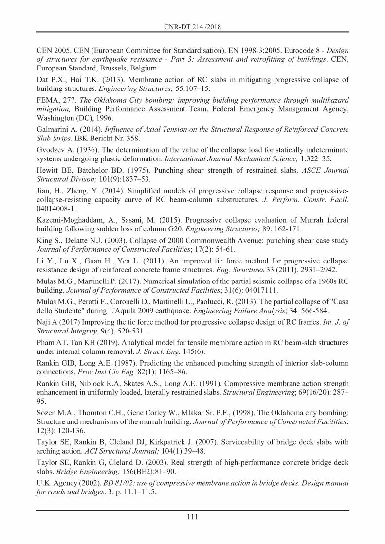
CNR-DT 214 /2018
111
CEN 2005. CEN (European Committee for Standardisation). EN 1998-3:2005. Eurocode 8 - Design of structures for earthquake resistance - Part 3: Assessment and retrofitting of buildings. CEN, European Standard, Brussels, Belgium. Dat P.X., Hai T.K. (2013). Membrane action of RC slabs in mitigating progressive collapse of building structures. Engineering Structures; 55:107–15. FEMA, 277. The Oklahoma City bombing: improving building performance through multihazard mitigation, Building Performance Assessment Team, Federal Emergency Management Agency, Washington (DC), 1996. Galmarini A. (2014). Influence of Axial Tension on the Structural Response of Reinforced Concrete Slab Strips. IBK Bericht Nr. 358. Gvodzev A. (1936). The determination of the value of the collapse load for statically indeterminate systems undergoing plastic deformation. International Journal Mechanical Science; 1:322–35. Hewitt BE, Batchelor BD. (1975). Punching shear strength of restrained slabs. ASCE Journal Structural Divison; 101(9):1837–53. Jian, H., Zheng, Y. (2014). Simplified models of progressive collapse response and progressive-collapse-resisting capacity curve of RC beam-column substructures. J. Perform. Constr. Facil. 04014008-1. Kazemi-Moghaddam, A., Sasani, M. (2015). Progressive collapse evaluation of Murrah federal building following sudden loss of column G20. Engineering Structures; 89: 162-171. King S., Delatte N.J. (2003). Collapse of 2000 Commonwealth Avenue: punching shear case study Journal of Performance of Constructed Facilities; 17(2): 54-61. Li Y., Lu X., Guan H., Yea L. (2011). An improved tie force method for progressive collapse resistance design of reinforced concrete frame structures. Eng. Structures 33 (2011), 2931–2942. Mulas M.G., Martinelli P. (2017). Numerical simulation of the partial seismic collapse of a 1960s RC building. Journal of Performance of Constructed Facilities; 31(6): 04017111. Mulas M.G., Perotti F., Coronelli D., Martinelli L., Paolucci, R. (2013). The partial collapse of "Casa dello Studente" during L'Aquila 2009 earthquake. Engineering Failure Analysis; 34: 566-584. Naji A (2017) Improving the tie force method for progressive collapse design of RC frames. Int. J. of Structural Integrity, 9(4), 520-531. Pham AT, Tan KH (2019). Analytical model for tensile membrane action in RC beam-slab structures under internal column removal. J. Struct. Eng. 145(6). Rankin GIB, Long A.E. (1987). Predicting the enhanced punching strength of interior slab-column connections. Proc Inst Civ Eng. 82(1): 1165–86. Rankin GIB, Niblock R.A, Skates A.S., Long A.E. (1991). Compressive membrane action strength enhancement in uniformly loaded, laterally restrained slabs. Structural Engineering; 69(16/20): 287–95. Sozen M.A., Thornton C.H., Gene Corley W., Mlakar Sr. P.F., (1998). The Oklahoma city bombing: Structure and mechanisms of the murrah building. Journal of Performance of Constructed Facilities; 12(3): 120-136. Taylor SE, Rankin B, Cleland DJ, Kirkpatrick J. (2007). Serviceability of bridge deck slabs with arching action. ACI Structural Journal; 104(1):39–48. Taylor SE, Rankin G, Cleland D. (2003). Real strength of high-performance concrete bridge deck slabs. Bridge Engineering; 156(BE2):81–90. U.K. Agency (2002). BD 81/02: use of compressive membrane action in bridge decks. Design manual for roads and bridges. 3. p. 11.1–11.5.

CNR-DT 214 /2018
112
Vecchio F., Collins M. (1990). Investigating the collapse of a warehouse. Concrete International; 12(3):72–8. Reinforced concrete precast structures Arslan M.H., Korkmaz H.H., Gulay F.G. (2006). Damage and failure pattern of prefabricated structures after major earthquakes in Turkey and shortfalls of the Turkish Earthquake code. Engineering Failure Analysis; 13:537–57. Belletti B., Damoni C., Scolari M., Stocchi A. (2014). Study of brittle failure modes of precast roof elements connected to the beams with steel dowels. EURO-C 2014, St. Anton am Arlberg, Austria; 24 – 27 March, 2: 871-881 Bournas D.A., Negro P., Taucer F.F. (2013). Performance of industrial buildings during the Emilia earthquakes in Northern Italy and recommendations for their strengthening. Bulletin of Earthquake Engineering; 12(5):2383–2404. Bovo M., Savoia M. (2018). Numerical simulation of seismic-induced failure of a precast structure during the Emilia Earthquake, Journal of Performance of Constructed Facilities ASCE; 32(1) 04017119. Ercolino M., Magliulo G., Manfredi G. (2016). Failure of a precast RC building due to Emilia-Romagna earthquakes. Engineering Structures;118:262–73. fib bulletin 63 (2012). Design of precast concrete structures against accidental actions. Fédération Internationale du béton, Lausanne (CH), 78 pages, ISBN 978-2-88394-103-8. Ghosh S.K., Cleland N. Observations from the February 27, earthquake in Chile. PCI J 2012;57:52–75. Liberatore L., Sorrentino L., Liberatore D., Decanini L.D. (2013). Failure of industrial structures induced by the Emilia (Italy) 2012 earthquakes. Engineering Failure Analysis; 34:629–47. Ligabue V., Bovo M., Savoia M. (2014). Connessioni tegolo-trave: studio sperimentale e numerico del comportamento di angolari di collegamento. CTE – ACI Workshop: Tecniche Innovative per il miglioramento sismico di edifici prefabbricati, Bologna, ImReady ed., 75-84. Magliulo G., Capozzi V., Fabbrocino G., Manfredi G., (2011). Neoprene–concrete friction relationships for seismic assessment of existing precast buildings. Engineering Structures; 33:532–8. Magliulo G., Ercolino M., Petrone C., Coppola O., Manfredi G. (2014). The Emilia Earthquake: seismic performance of precast Reinforced Concrete buildings. Earthquake Spectra; 30:891–912. Minghini F., Ongaretto E., Ligabue V., Savoia M., Tullini N. (2016). Observational failure analysis of precast buildings after the 2012 Emilia earthquakes. Earthquakes and Structures; 11(2):327-346. Ravasini S., Scalvenzi M., Parisi F., Belletti B., Gasperi A. (2020). Evaluation of structural robustness of precast RC structures. Italian Concrete Days 2020. Napoli, Italia; 14 – 17 Aprile. Reluis (2008), Strutture prefabbricate: catalogo delle tipologie esistenti, Linea di ricerca 2: Valutazione e riduzione della vulnerabilità degli edifici esistenti in c.a; Obiettivo 2.9: Comportamento e rinforzo di strutture industriali prefabbricate. Reluis (Gruppo di Lavoro Agibilità Sismica dei Capannoni Industriali) (2012), “Linee di indirizzo per interventi locali e globali su edifici industriali monopiano non progettati con criteri antisismici”. Savoia M., Buratti N., Vincenzi L. (2017). Damage and collapses in industrial precast buildings after the 2012 Emilia earthquake; Engineering Structures; 137:162-180. Toniolo G., Colombo A. (2012) Precast concrete structures: The lessons learned from the L’Aquila earthquake. Structural Concrete;13:73–83.

CNR-DT 214 /2018
113
Steel constructions Davies J.M., Brown B.A. (1996). Plastic design to BS 5950. The Steel Construction Institute Dusenberry D. O., L’ambiance plaza – case study, http://www.bfrl.nist.gov/861/861pubs /collapse/workshop/7.L’AmbiancePlazaCaseStudy060913.pdf Heger F. J., (2006) L’ambiance plaza. http://www.engineering.com/Library/ArticlesPage /tabid/85/PageID/182/ArticleID/168/articleType/ArticleView/Default.aspx . Kokot S., Solomos G., (2011). Progressive collapse risk analysis: literature survey, relevant con-struction standards and guidelines. JRC Technical Report, No JRC 32253-2011. Ellingwood B.R., Smilowitz R., Dusenberry D.O., Duthinh D., Carino N.J. (2007). Best Practic-es for Reducing the Potential for Progressive Collapse in Buildings. National Institute of Standards and Technology, NISTIR 7396. Levy M., Salvadori M. Perché gli edifici cadono, Bompiani, 1997, ISBN: 8845231070 Moore D. B., “The UK and European Regulations for Accidental Actions,” in National Workshop on Prevention of Progressive Collapse in Rosemont, III, Multihazard Mitigation Council of the Na-tional Institute of Building Sciences, Washington, DC. 2002. FEMA, FEMA 403 ‘World Trade Center Building Performance Study’ 2002. National Institute of Science and Technology (NIST), 2005. Final Report on the Collapse of the World Trade Centre Towers (NCSTAR 1); Federal Building and Fire Safety Investigations of the World Trade Centre Disaster. US Department of Commerce, Gaithersburg, MD, USA. National Institute of Science and Technology (NIST), 2008. Final Report on the Collapse of the World Trade Center Building 7. NIST NCSTAR 1A. Gaithersburg, MD. Available from: www.nist.gov Wong M. B. (2009). Plastic Analysis and Design of Steel Structures (1st Edition ed.). Oxford, England: Elsevier Ltd CEN 2005. CEN (European Committee for Standardization), Design of steel structures, part 1.8: Design of joints, EN 1993:1-8, Brussels, 2005. CEN 2005. CEN (European Committee for Standardization), Design of steel structures. Part 1-1: General rules and rules for buildings, EN 1993-1-1, Brussels, 2005. Cassiano D., D’Aniello M., Rebelo C., Landolfo R., da Silva L. (2016). Influence of seismic de-sign rules on the robustness of steel moment resisting frames. Steel and Composite Structures, An International Journal; 21(3): 479-500. Cassiano D., D’Aniello M., Rebelo C. (2017) Parametric finite element analyses on flush end-plate joints under column removal. Journal of Construct Steel Research; 137: 77–92. D'Aniello M., Tartaglia R., Costanzo S., Landolfo R. (2017). Seismic design of extended stiff-ened end-plate joints in the framework of Eurocodes. Journal of Construct Steel Research; 128: 512–527. Tartaglia R., D’Aniello M., Rassati G.A., Swanson J.A., Landolfo R. (2018). Full strength ex-tended stiffened end-plate joints: AISC vs recent European design criteria. Engineering Structures; 159(15): 155–171. Tartaglia R., D’Aniello M., De Martino A. (2018). The ultimate performance loss of external end-plate bolted joints under column accounting for the presence of transverse beams. The Open Con-struction and Building Technology Journal; 12, (Suppl-1, M7), 2018, Pages 132-139. Timber constructions

CNR-DT 214 /2018
114
Blaß H.-J., Frese M. (2007). Failure analysis on timber structures in Germany - A contribution to COST Action E55, 1st Workshop. Graz University of Technology, Austria. CEN 2004. CEN (European Committee for Standardisation). EN 1992-1-1:2004. Eurocode 2 - Design of concrete structures - Part 1-1: General rules and rules for buildings. CEN, European Standard, Brussels, Belgium. CEN 2006. CEN (European Committee for Standardisation). EN 1991-1-7:2006. Eurocode 1 - Actions on structures. Part 1-7: General actions - Accidental actions. CEN, European Standard, Brussels, Belgium. COST Action E55 (2010). Modelling of the performance of timber structures. Guideline - Design for robustness of timber structures. Sørensen J.D., Dietsch P., Kirkegaard P.H., Munch-Andersen J., Cizmar D., Neves L., Branco J., Zhang B., Fink G., Steiger R., Köhler J., Rajcic V., Turk G., Winter S., Frühwald E., Serrano E., Toratti T., Emilsson A., Thelandersson S. (2007). Design of safe timber structures – How can we learn from structural failures in concrete, steel and timber, Report TVBK-3053. Div. of Struct. Eng., Lund University. Dietsch P., Winter S. (2009). Assessment of the structural reliability of all wide span timber structures under the responsibility of the City of Munich. 33rd IABSE Symposium, Bangkok, Thailand. Dietsch P. (2011). Robustness of large-span timber roof structures. Structural aspects, Engineering Structures; 33(11): 3106–3112. Ellingwood B. R. Leyendecker E. V. (1978). Approaches for design against progressive col-lapse. J Structural Divison ASCE; 104: 413-423. Hewson N. (2016) Robustness in Structures. Melbourne: Forest and Wood Products Australia Limited. Huber J.A.J., Ekevad M., Girhammar U.A., Berg S. (2018). Structural robustness and timber buildings – a review, Wood Material Science & Engineering, doi: 10.1080/17480272.2018.1446052. Open Access. Lew H.S., Bao Y., Sadek F., Main, J.A., Pujol S., Sozen M. (2011). An Experimental and Computational Study of Reinforced Concrete Assemblies under a Column Removal Scenario, NIST Technical Note - 1720. Sørensen J.D. (2011). Framework for robustness assessment of timber structures, Engineering Structures; 33: 3087-3092, doi: 10.1016/j.engstruct.2011.02.025

CNR-DT 214 /2018
115
7 PROBABILISTIC AND SEMI-PROBABILISTIC QUANTIFICATION OF ROBUSTNESS
7.1. PROBABILISTIC AND SEMI-PROBABILISTIC APPROACHES Current codes and standards consider a relatively small set of possible events that could threaten the safety and performance of a structural system (see Chapter 2), as well as the mitigation of associated risks. Nonetheless, the evolution of construction practice and socio-political events highlighted the need to investigate some additional risks that were not normally considered in structural design (such as explosions) or for which a "deemed-to-satisfy" approach was used through check-lists rather than structural calculations. The consideration of these risks through a consistent approach is currently recognized as a prerequisite to ensure the effective management of structural safety, to maximize the recovery of economic investments, and to produce regulatory provisions aimed at improving construction practice. In a design context, it is neither economically nor technically possible to consider in detail any event that could potentially affect the structural performance of a building. Hazardous events may have different impacts depending on the target risk under consideration. For example, the detonation of an explosive may have either a minor effect or a considerable impact on risk if the target probability of collapse P[C] is 10-5/year or 10-7/year, respectively. The reference time period may be another important factor to take into account. Different representations of exposure are provided for annual risks compared to those determined on a 50-year or 100-year time basis; this may also have an influence on decision making. The comparison between different types of hazardous events may allow stakeholders and decision makers to exclude trivial risks, focusing only on events that may lead to an unacceptable increase in the collapse rate of a building (hence exceeding the de minimis risk) and selecting appropriate risk mitigation strategies. The conditional probabilities into equation (3.8) may be estimated through probabilistic risk analysis (PRA), which allows modelling and propagation of uncertainties up to the analysis of their effects on system performance. In the case of structural systems, this approach is called structural reliability analysis, and failure (i.e., collapse in this context) is achieved when demand S (i.e., the effects of actions) exceeds capacity R. The failure probability is given by:
where is the cumulative distribution function of capacity R and is the probability density function of demand S. Both R and S must be expressed through either a scalar or vector-valued measure, which depends on either the load type or the initial state of damage. The disproportionate collapse probability can be equivalently defined as follows:
where is the reliability index (or safety index) and ( ) is the normal standard distribution function. To carry out a performance-based design or assessment of a structure, decision makers should first define a tolerable risk level, that is, the amount of risk that could be accepted for the structure under consideration. As the main consequence of collapse is the loss of life, decision makers may assume that the performance objective of life safety is achieved if the following relationship is met:
where pth is the de minimis risk, which can be considered ranging between 10-7/year and 10-5/year (Paté-Cornell, 1994; Stewart and Melchers, 1997; Russo and Parisi, 2016), depending on the type of risk under analysis.
(7.1)
or (7.2)
(7.3)

CNR-DT 214 /2018
116
If the alternative load path method is used (see Chapter 5), the collapse probability reduces to P[C|LS] and can be computed by convolution of demand and capacity. Accordingly, the conditional probability of collapse should meet the following condition:
Assuming H equal to 10-6–10-5/year, the performance objective set through inequality (7.4) requires that the conditional probability of collapse be in the order of 10-2–10-1/year. The latter value is thus the target probability, which turns out to be two or three orders of magnitude higher than that related to structural components and systems. This is due to the conditional nature of the limit state of disproportionate collapse defined by inequality (7.4). Consequently, the target reliability index 0 for the collapse limit state conditioned upon damage occurrence will be in the order of 1.5, that is significantly lower than that assumed for the ultimate limit state of new residential buildings subjected to ordinary actions (i.e., 0 = 3.8, corresponding to a target probability of collapse in the order of 10-
4). Conditional probabilities of local damage and disproportionate collapse can be assessed by means of fragility analysis, which is a well-established method in earthquake engineering (Porter et al., 2007) and was also extended to quantitative assessment of other risks (Asprone et al., 2010; Parisi 2015; Olmati et al., 2016). Therefore, given that the lack of robustness is an unfavourable situation for which the probability of occurrence has to be very low, the de minimis concept proposed by Paté-Cornell (1994) and recalled in Section 3.2 can be effectively used. At least in the case of buildings, that approach establishes that an event with annual probability of occurrence lower than 1x10⁻⁷/year may be neglected in structural conceptual design. If ordinary buildings with nominal lifetime of 50 years (hence falling in consequence class 2) are considered, the annual probability of event occurrence turns out to be in the order of 5x10⁻⁶/50 years. As the reliability index of an ordinary structure falling in consequence class 2 is = 3.8 and is associated with a failure probability in the order of 7.3x10⁻⁵, according to a conditional probability approach, the occurrence probability of structural collapse after a local failure (i.e., event related to the lack of robustness) must be withstood through a further term in the order of 6.9x10⁻²/50 years (i.e., with 1.5 in a 50-year nominal lifetime of the structure). The global safety format for structural assessment allows the estimation of the global structural resistance based on mean values of material properties (e.g., using a nonlinear finite element simulation) and the evaluation of design structural resistance as ratio between mean (computed) resistance and global safety factor R related to the global behavior of the structure. If a lognormal probability distribution is assigned to global resistance (consistently with the assumption on random material properties), the global safety factor R should be evaluated as a function of and of the coefficient of variation VR of global resistance, as follows:
In the absence of more accurate outcomes by nonlinear finite element simulations combined with Monte Carlo random sampling (or other simulation methods), the assumption of a conservative value VR = 0.15 produces R 1.20. This value must be multiplied by the model uncertainty factor Rd that ranges between 1.06 (for beam elements) and 1.15 (for 2D and 3D elements), depending on the type of finite elements used in numerical simulations for the computation of the mean global resistance. If local and/or sectional safety verifications are carried out via simplified approaches (i.e., without refined nonlinear finite element simulations), the partial safety factors of materials should be evaluated as follows:
resulting in:
| (7.4)
0.8 1.5 (7.5)
1.645 1.645 (7.6)
CNR-DT 214 /2018
117
- c = 1.01 1.00 for concrete with Vx = 0.15 and Rd = 1.08; - s = 1.00 for reinforcing steel with Vx = 0.05 and Rd = 1.025.
7.2. ROBUSTNESS MEASURES The quantification of structural robustness through appropriate measures is a key point for an effective assessment and mitigation of disproportionate collapse risk. A comprehensive literature review allows distinguishing between different robustness measures according to (i) their dependence or independence on the hazardous event and (ii) the deterministic or probabilistic approach adopted (Adam et al., 2018). Robustness measures should have several important attributes (Lind, 1995; Starossek, 2018). First, an appropriate measure should provide a good description of the main factors influencing robustness, allowing a clear distinction between robust and non-robust structures. It is worth noting that each measure should be in turn a robust indicator, meaning that the measure should not be sensitive to modelling options of risk components, i.e., hazard, vulnerability and exposure. Other attributes of robustness measures involve simplicity in their definition, computation and applicability to different types of construction. Nevertheless, the expressiveness of the measure and its applicability to multiple structures may be improved if a (sometimes significant) increase in computational cost is tolerated. This highlights a possible conflict between some of the abovementioned attributes that, in line of principle, should characterize a robustness measure (Starossek and Haberland, 2011). Some researchers proposed probabilistic robustness measures that compare either the risk of disproportionate collapse or failure probability or reliability index of a locally damaged structure to their respective values related to the as-built (undamaged) structure, i.e., the structure before local damage occurs (Frangopol and Curley, 1987; Baker et al., 2008; Sørensen, 2011). Other researchers proposed deterministic or semi-probabilistic measures that quantify robustness by comparing, for instance, the total gravity load resisted by the locally damaged structure (i.e., the residual vertical load-bearing capacity) to the design gravity load (i.e., the vertical load-bearing resistance demand defined by building codes under exceptional design conditions) (Frangopol and Curley, 1987; Parisi and Augenti, 2012). Accordingly, the structural robustness of a building may be expressed by a capacity-to-demand ratio, or equivalently through a global safety factor that is associated with exceptional conditions in terms of localized damage and gravity loads on floors. In the framework of the alternative load path method, measures based on a capacity-to-demand ratio allow quantifying structural robustness regardless of the event that may cause local damage. Section Errore. L'origine riferimento non è stata trovata., in the chapter “bridge design for robustness”, deals with the criteria to define robustness, with the definition of robustness indexes in the specific case of bridges, reporting also some explanatory examples.
7.3. REFERENCES Adam, J., Parisi, F., Sagaseta, J., Lu, X. (2018). Research and practice on progressive collapse and robustness of building structures in the 21st century. Engineering Structures; 173: 122-149. Asprone, D., Jalayer, F., Prota, A., Manfredi, G. (2010). Proposal of a probabilistic model for multi-hazard risk assessment of structures in seismic zones subjected to blast for the limit state of collapse. Structural Safety; 32(1): 25-34. Olmati, P., Petrini, F., Vamvatsikos, D., Gantes, C. (2016). Simplified fragility-based risk analysis for impulse governed blast loading scenarios. Engineering Structures; 117: 457-469. Baker, J.W., Schubert, M., Faber, M.H. (2008). On the assessment of robustness. Structural Safety; 30(3): 253-267. Frangopol, D.M., Curley, J.P. (1987). Effects of damage and redundancy on structural reliability. Journal of Structural Engineering; 113: 1533-1549.

CNR-DT 214 /2018
118
Lind, N.C. (1995). A measure of vulnerability and damage tolerance. Reliability Engineering and System Safety; 48(1): 1-6. Parisi, F. (2015). Blast fragility and performance-based pressure–impulse diagrams of European re-inforced concrete columns. Engineering Structures; 103: 285-297. Parisi, F., Augenti, N. (2012). Influence of seismic design criteria on blast resistance of RC framed buildings: A case study. Engineering Structures; 44: 78-93. Paté-Cornell, M.E. (1994). Quantitative safety goals for risk management of industrial facilities. Structural Safety; 13(3): 145-157. Porter, K., Kennedy, R., Bachman, R. (2007). Creating fragility functions for performance-based earthquake engineering. Earthquake Spectra; 23(2): 471-489. Russo, P., Parisi, F. (2016). Risk-targeted safety distance of reinforced concrete buildings from natural-gas transmission pipelines. Reliability Engineering and System Safety; 148: 57-66. Stewart, M., Melchers, R.E. (1997). Probabilistic risk assessment of engineering systems. Springer. Starossek, U. (2018). Progressive collapse of structures. 2nd ed. Thomas Telford Limited. Starossek, U., Haberland, M. (2011). Approaches to measures of structural robustness. Structure and Infrastructure Engineering; 7: 625-631. Sørensen, J.D. (2011). Framework for robustness assessment of timber structures. Engineering Structures; 33(11): 3087-3092.

CNR-DT 214 /2018
119
8 BRIDGE DESIGN FOR ROBUSTNESS
8.1 PREFACE Bridges are intrinsically structures where robustness criteria are very important, being structures where the static scheme is carefully designed in order to maintain the overall weight limited as possible. Isostatic bridges or with a low degree of structural redundancy are typical solutions, for the ease in construction phases, to reduce the effects of thermal loadings and consequent possible degradation phenomena, and then it is difficult to adopt some robustness strategies such as the alternative load path, so effective in the case of buildings. On the other hand, they are strategic structures, and then issues of public safety as well as of efficiency of the road network in a country are key aspect in their design. In order to maintain the safety level unchanged with respect to the original design, maintenance, repair and other future improvements must be planned in the advance, and their require inspection activities be carefully predicted at the design stage. In the design for robustness of a bridge, exceptional loads, such as exceptional transit weights, but also environmental actions above the code design prescriptions as well as those due to human activities (fire, impact, etc, see Sections 2.7-2.9) are also possible and must be taken into account. Examples of how to evaluate the robustness performances in bridges subjected to extreme events and multi-hazard conditions can be found in Echevarri et al. (2016), Alipour et al. (2011). In the case of relevant bridges, those actions are considered using scenario-based risk analyses. In the following some relevant and famous collapses of bridges in the past will be briefly described, and some criteria concerning design for robustness will be given and commented. In view of the sensitivity of the subject, only collapses whose legal process is presently concluded and the causes clearly stated are illustrated.
8.1.1 Collapse and robustness of bridges The development of modern bridges during 19th century was characterized by important steps, leading to reach span lengths which were not imaginable before. But this progress was alternated by a series of collapses, mainly due to lack of robustness. Nevertheless, each collapse case represented a lesson to be learned, which was fundamental to contribute to the progress in bridge design. One of the most famous collapses concerns the first Tacoma Narrows Bridge, Washington State, U.S.A, Figure 8-1. It is the most classical example of an action (the wind) not correctly considered in design due to the limited knowledge at that time. Tacoma was the very first bridge to incorporate a series of plate girders as roadbed support, and the first bridge of its type (cable suspension). Just shortly after the construction, it was found to be very flexible, and to dangerously buckle and sway along its length in normal windy conditions. Four months after the opening, on the morning of November 7, 1940, it suffered collapse in a wind of about 67 km per hour. The 840 - meter main span went into a series of torsional oscillations, whose amplitude steadily increased until the convolutions tore several suspenders loose, changing its vibration frequency from 36 to 14 cycles/min, and the span broke up. The section formed by the roadway and stiffening plate girders (rather than web trusses) did not absorb the turbulence of wind gusts, making the bridge highly vulnerable to aerodynamic forces, insufficiently understood at the time. The failure, which took no lives because the bridge was closed to traffic in time, spurred aerodynamic research and led to important advances. Moreover, the plate girder design for suspension bridges was abandoned. The Tacoma Narrows Bridge collapsed primarily due to the aeroelastic flutter. In ordinary bridge design, the wind is allowed to pass through the structure by incorporating steel trusses in the lower part of the bridge. In contrast, in the case of the Tacoma Narrows Bridge, the wind was forced to move above and below the structure, leading to flow separation. Such flow separation, in the presence of an object, can lead to the development of a Kármán vortex street, as the flow passes through the object.

CNR-DT 214 /2018
120
a) b)
Figure 8-1 – The Tacoma Narrows Bridge: a) opening day; b) collapse (Source: by University of Washington Libraries Digital Collections, via Wikimedia Commons)
A very famous bridge collapse occurred on 25 October 1960, in England, on Severn railway Bridge (Figure 8-2), due to the collision of two barges, during a day of thick fog and a strong tide. The bridge was originally designed to carry coal from a local company and subsequently used for freight and passenger services. It had twenty-one spans, and was 1200 m long and 21 m high above sea level. The pier columns were constituted by circular sections, bolted together and filled with concrete, supporting regular wrought iron spans. The two barges collided with one of the columns of the bridge after being carried upstream, and two bridge spans collapsed into the river. As they fell, parts of the structure hit the barges causing the fuel oil and petroleum they were carrying to catch fire. Five people died in the incident and the 12-inch (30 cm) diameter gas main tube was damaged. Before that event, a number of accidents took place at the bridge over the years, with vessels colliding with the piers due to the strong tides. For that reason, the subsequent years the bridge was demolished.
a) b)
Figure 8-2 – The Severn railway bridge: a) after the collapse of two spans in 1960; b) the demoli-tion of the bridge. In the second picture the structure of the bridge can be clearly seen, as well as the
protection of the pier base, which resulted to be insufficient

CNR-DT 214 /2018
121
Among the collapses involving steel bridges, the collapse of the railway Tay Bridge (UK) in 1879 resulted in the deaths of 75 passengers and staff (Figure 8-3). The lesson was that cast iron is a very brittle material and must be avoided especially when fatigue loading is involved.
Figure 8-3 – Collapse of the railway Tay bridge (UK) in 1879
At the beginning of 20th century, a sensational case was the double collapse of the Quebec bridge on the San Lorenzo River in Canada (Figure 8-4). In August 1907 the main span of the bridge collapsed during the erection by a cantilever method, due to buckling of some compressed bars of the steel truss; 75 workers died (Figure 8-5a). A mixed US-Canada inquiry Commission was appointed for analysing the collapse reasons and for suggesting a new safe erection system. After about 9 years, the Commission stated the impossibility to erect the whole central part of the bridge with 375 m span by means of the cantilever system. A new erection design was done based on the lifting of the whole central part of the bridge by using jacks supported on pontoons. In September 1916, during the new erection, when the 2500 tons of the central part of the bridge were lifted of 4 m, the bridge collapsed into the river; 13 workers died (Figure 8-5b). The reason of this tragedy can mainly be attributed to errors produced by the lack of technical knowledge.
Figure 8-4 – Quebec bridge on the San Lorenzo River in Canada

CNR-DT 214 /2018
122
a) b)
Figure 8-5 – Quebec bridge (1907): a) first collapse; b) second collapse (1916) In the period 1969-1971, four steel bridges collapsed during the erection, causing about 50 victims in different countries. They were: the bridge on the Danube River in Vienna (A), the Cleddau Bridge in Milford Haven (UK) (Figure 8-6a), the bridge on the Rhine River in Koblenz (D), the West Gate Bridge in Melbourne (AUS) (Figure 8-6b). These bridges were characterized by the same type of steel deck made of orthotropic stiffened plates. The reason of this multiple collapse was the local buckling of the steel plates, due to a non-conservative interpretation of new design rules, leading to an excessive reduction of the stiffness (Ballio et al, 2020).
a) b) Figure 8-6 – a) collapse of Cleddau Bridge in Milford Haven (UK); b) collapse of West Gate Bridge
in Melbourne (AUS) More recently, in 2007 the I-35W Mississippi River bridge, an eight-lane steel truss arch bridge, (officially known as Bridge 9340) collapsed during an evening rush hour, with more than 100 vehicles involved and 13 people killed, see Figure 8-7. In the years prior to the collapse, several reports cited problems with the bridge structure. In 1990, the federal government gave the I-35W bridge a rating of "structurally deficient", citing significant corrosion in its bearings and other structural elements. A report from the University of Minnesota indicated a concern about lack of redundancy in the main truss system, which meant the bridge had a greater risk of collapse in the event of any single structural failure, although the report concluded that the bridge should not have any problems with fatigue cracking in the foreseeable future. According to the reports after investigation, the National Transportation Safety Board's Office announced that the collapse was due to the steel gusset plates connecting the main structural elements which were undersized and inadequate to support the intended load of the bridge, a load that had increased over time during repair and rehabilitation intervention in 1998 and construction materials and equipment in preparation of a deck paving operation. According to Ballarini and Okazaki (2009), the thickness of the gusset plates at the node which experienced failure was ½ inch instead of 1 inch, and the elastic

CNR-DT 214 /2018
123
safety factor with respect to the design service loads was approximately equal to 1.0, instead of 2.0 required by the design code in 1967.
Figure 8-7 – Collapse of the I-35W Mississippi River bridge in Minneapolis, Minnesota, United
States (images from the National Transportation Safety Board's Office of Research and Engineering and Liao and Okazaki, 2009, Ballarini and Okazaki, 2009)
A famous collapse involving a reinforced concrete bridge concerns the General Rafael Urdaneta Bridge, Lake Maracaibo, Venezuela, Figure 8-8. Made of reinforced and prestressed concrete, the cable-stayed bridge carries only vehicles and spans 8.678 kilometers from shore to shore. The five

CNR-DT 214 /2018
124
main spans are each 235 meters long. They are supported by 92-meter tall towers, and provide 46 meters of clearance to the water below. The competition to design the bridge was won by the Italian bridge designer Riccardo Morandi. It was the only concrete design out of twelve entries, and was expected to be less expensive to maintain, as well as providing valuable experience of prestressed concrete technology. On 6 April 1964 a petroleum tanker, carrying 236,000 barrels (37,500 m3) of crude oil, lost her steering because of an electrical malfunction. Unable to navigate, the ship first hit two lateral piers of the bridge, n 31 and n. 32. This led to the collapse of a 259- meter (849 ft 9 in) long section of the bridge. The collapsed bridge sections were rebuilt in height months,
a) b)
Figure 8-8 – The General Rafael Urdaneta Bridge, Lake Maracaibo, Venezuela: a) view of the bridge; b) an image of collapse of two pier due to the impact of a large petroleum tanker
The Tasman Bridge was a reinforced concrete bridge near Hobart, Australia, 1396 m long. On the evening of 5 January 1975, the bulk carrier Lake Illawarra, carrying 10,000 tonnes of zinc ore concentrate travelling up the Derwent River collided with several piers of the Tasman Bridge, causing the collapse of two piers and three spans of deck supported by them (Australian Bureau of Statistics, 2000; Mondorf, 2006; Scheer, 2000-2001). The other 19 spans remained intact after the ship collision (Figure 8-9). The bridge deck was made of precast prestressed concrete beams. In relation to the Tasman Bridge collapse, Starossek (2017) reported that “the absence of failure progression and thus the robustness of that bridge are apparently related to the discontinuity of prestressing tendons between adjacent spans. Interestingly, preventing progressive collapse was an original design intent. Hence, even though the deck slab was continuous over the supports, the longitudinal concrete reinforcing bars in the slab were interrupted there and locally spliced with light reinforcement of limited well-defined yield strength. Furthermore, the diaphragms over the supports were split in half and connected to one another using keyed joints – a measure that allowed the transfer of compression and shear but not of tension”.

CNR-DT 214 /2018
125
Figure 8-9 – Collapse of the Tasman bridge in Hobart (Australia) (from Tasmanian Archives and
Heritage Office) A more recent bridge collapse occurred in Italy, and involved the Annone overpass, Lecco, on October 28, 2016, causing the death of a car driver and four wounded. The bridge was built between the 1960 and 1962 and consisted of three spans and four supports with a Gerber scheme ( a) b) Figure 8-10). The central deck, 24.60 m long and 6.40 m wide, was made by 5 precast and prestressed I-beams. The bridge collapse occurred when a heavy 8-axels truck (107.6 t) went across the deck. Once the load was carried entirely by the central beam, the external dapped-end corbel collapsed. According to the post-collapse investigation (di Prisco et al., 2018), several factors contributed to this failure. Among these:
- the bridge was designed for the transit of civilian loads only (roads of local or local interest) corresponding to indefinite column of 12 t trucks, with two axes, 4 t and 8 t, 6 m long, for a total of 36 t each lane
- the dapped-end corbels were affected by an initial design error that reduced the safety condition of these critical connections;
- the heavy truck loads, crossing the bridge for many years, forced the reaction of the external dapped-end joint to a value close to its ultimate load;
- a shear crack propagated in the collapsed dapped end corbel and favoured the oxidation of the reinforcement, significantly reducing the bearing capacity of the corbel and producing a 25 mm settlement of that support.
This collapse demonstrated that a theoretical statically determined structure can exploit a significant level of redistribution guaranteed by the interaction between the five prefabricated beams. Nevertheless, a significant redistribution does not imply a large robustness and the collapse of one dapped-end caused the collapse of the whole overpass.

CNR-DT 214 /2018
126
a) b) Figure 8-10 – View of the Annone overpass: a) before the collapse; b) after the collapse (di Prisco
et al., 2018)
8.1.2 Effect of material degradation Even though this document is dedicated to the assessment and design of new bridges, it is very important to remember that degradation of the structure due to aggressive environment may be the cause of brittle and sudden collapses, particularly in the presence of design errors or construction defects and in bridges with non statically redundant schemes. Hence, design criteria and prescriptions to reduce the effect of structural degradation during the lifetime of the bridge, as well as to allow periodic inspections on its main elements, are a key issue to be considered in design. For instance, the exposure to aggressive environments due to natural events or the use of salts for the icing of the road pavement can be very detrimental for some structures because they can cause aging and degradation phenomena (e.g., Cavaco et al., 2018). The robustness assessment of both new and existing bridges is of special importance for maintenance optimisation. Indeed, low levels of bridge robustness to aging and aggressive environment attacks require more financial resources for maintenance, monitoring and inspections. Reinforced concrete (RC) and prestressed concrete (PC) bridges can be subjected to material degradation and deterioration induced by aggressive environment, alkali aggregate reactions, frost actions, and inaccurate installation or maintenance of rainwater system. Corrosion, which is induced by carbonation or chloride ions intrusion, may affect bridges exposed to urban or marine environmental attack. Corrosion rate in bridges is also dependent on the exposure to relative humidity and temperature cycles, use of de-icing salt or other chemical agents. Typical effects of corrosion are reinforcement depassivation, cracking, cover spalling, uniform reduction of reinforcement diameter or pitting, and decay of bond resistance and mechanical properties. The bridge components that are typically affected by corrosion are bridge piers, bridge girders, cantilevers, prestressing or suspension cables, joints, and connections. The robustness of deteriorated bridges depends on the damage scenario under consideration. In addition, the relation between the damage level of a deteriorated bridge component, its propagation within the structural system and the progressive collapse mechanism depends on the structural scheme of the bridge. Bridge piers can be affected by corrosion of longitudinal and transversal reinforcement, which may also cause buckling of longitudinal bars, for instance in case of seismic ground motion. Bridge girders can be affected by corrosion of wires, both distributed along the reinforcement and localized, due to hydrogen embrittlement, stress corrosion cracking and fatigue resistance decay. In the case of post-tensioned tendons, corrosion may be activated in zones with inadequate duct grouting or tendons protection. This deterioration process is also facilitated by concrete discontinuities that may occur during bridge construction. Corrosion may cause reduction of the resisting area and strong decrease of the capacity of its structural elements. It may also cause bond resistance decay and then longer transmission lengths of forces from wires to concrete.

CNR-DT 214 /2018
127
In non statically redundant bridges (Sect. 8.3.1), corrosion may lead to brittle collapse, as observed in bridges with corroded Gerber saddle supports or joints. In statically redundant bridges such as multi-span bridges or cable stayed bridges (Sect. 8.3.2), the redundancy of the structural system may allow the activation of alternative load paths in case of corrosion. In the literature, probabilistic structural robustness indicators have been proposed to quantify the effects of corrosion in bridges (Biondini and Restelli, 2008; Cavaco et al., 2013; Cavaco et al., 2018). Nonetheless, research is still strongly needed to investigate progressive collapse resistance and robustness of deteriorated bridges, considering the interaction between continuous damage due to material degradation and discontinuous damage due to accidental events (e.g., vehicle or ship impact).
8.2 ACTIONS AND GOALS IN DESIGN FOR ROBUSTNESS OF BRIDGES
8.2.1 Accidental actions and/or extreme events The list of actions to account for accident-related or malicious events is given in Chapter 2. With reference to the design of bridges for robustness, the main actions to be considered are reported in the following sub-sections. These actions can be differentiated according to their nature in (i) natural induced actions and (ii) man induced actions. It is worth noting that also ordinary design actions can be included. For instance, permanent load, variable load and actions from wind, snow and earthquake can, with low probability, occur with more severity than usually considered in Codes.
8.2.1.1 Natural induced actions Natural induced actions may include:
- waves; - water current; - drifting ice; - corrosion.
8.2.1.2 Man induced actions Man induced actions may include:
- actions from ship collision; - fire caused by a traffic accident; - a bomb blast at a vulnerable location; - other accident-related or malicious events; - deficiencies in design or construction.
8.2.2 Criteria to define robustness The evaluation of the robustness of bridges and viaducts is a complex task due to the variety of static schemes adopted for the related design and construction. In fact, the structure of the same bridge can be realized adopting a combination of several elementary static schemes and the related robustness assessment requires particular care if compared to the case of ordinary frame buildings. Consequently, it is not simple to specify general rules to evaluate the robustness of the different typologies of bridges. Designers shall refer to the general approach of risk analysis (JCSS Probabilistic Model Code 2001, Baker et al. 2008, Radowitz et al. 2008) in which the combination of hazard, exposure, vulnerability and consequences of the system failure are considered. In this context, the risk of a disproportionate propagation of a local failure, with the corresponding “domino effect”, can be assessed considering predetermined damage scenarios. The most suitable operational tool to evaluate the robustness of a bridge or viaduct is based on the “event tree formulation”, in which all the possible unfavourable

CNR-DT 214 /2018
128
events (of voluntary or involuntary nature) during the reference period (e.g., one year or the design working life in case of new bridges and the residual working life in case of existing bridges) can be introduced, weighting the related probabilities and the expected costs for direct and indirect consequences.
8.2.2.1 Event tree formulation and robustness index In general, structural systems are interested by exposure events (Hj) of different nature (Radowitz et al 2008). The exposure events (Hj) can be characterized by permanent or variable loads, environmental actions (e.g., floods, landslides), deterioration processes and accidental actions (e.g., explosions, impacts of vehicles on and below the deck). The specific exposure event (Hj) may lead to different damage scenarios or, alternatively, to an undamaged scenario having both predetermined and complementary probability. With reference to situations where the undamaged scenario occurs, no consequences can be identified in general. Only in particular cases (e.g., in case of impacts of vehicles on the bridge or extreme environmental actions), some direct consequences may arise due to costs to perform the appropriate safety assessment of the structural members in order to be sure that the structure is still able to fulfil its performance requirements after the exposure event (Hj). For instance, excluding the cases where all the components of the structure remain in the undamaged state, several possible damage scenarios may occur with reference to the different structural members. The specific damage scenario can cause the failure of the structural system with different mechanisms and kinematics (i.e., event ) or not cause a failure (i.e., alternative event ). The different failure kinematics may give rise to potentially different evolution of the disproportionate failure and of the related consequences. In case of the event with a system failure , the nature and the extension of the failure mechanism may give rise to both direct and indirect consequences , . The direct consequences are related to the damage occurred to the structural members primary involved by the exposure events (Hj) and to related costs to recover them. The indirect consequences , are associated to all the consequences that arise in addition to the direct ones including, for an example, consequences due to the loss of functionality of the infrastructure and repercussions on the surrounding territory. The alternative event , associated with the damage scenario that does not give rise to the system failure, leads to direct consequences related to the damaged members only. The possible exposure events (Hj) and the related damage scenarios can be identified by means of engineering judgments of the practitioners/designers depending on the nature of the bridge (e.g., in terms of the global and the local static schemes, of the materials and geometrical configuration of the exposed members), the location of the bridge (e.g., the bridge crosses a river or another infrastructure), the type of the interested infrastructures (e.g., roads or railways, highway or principal or secondary roads), the relevance on the surrounding territory (e.g., part of connection between strategic industrial/energy plants or between other infrastructures as ports and airports, results of high indirect consequences in case of system failure due to absence or limited presence of alternative routes) and, finally, on the nature of the traffic that generally interest the infrastructure (e.g., high frequency of accidental loads, for an example, due to transportation of heavy products from steel industries). The scheme with the representation of the generic “event tree” suitable for risk analysis is depicted in Figure 8-11.

CNR-DT 214 /2018
129
Figure 8-11 – General representation of the “event tree formulation” for risk analysis
Finally, computing the probabilities related to both the possible exposure events and related damage scenarios within the “event tree formulation”, the total risk corresponding to the failure of the structural system due to a non-robust behavior can be evaluated according to the theoretical background introduced in Chapter 3. The computation of the total risk R provides the information associated to the expectation of the total consequences caused by the system failure over the reference period (Rackwitz, 2000). Although very often the reference period is set equal to the design working life for new infrastructures and to the residual working life for existing infrastructures, in the case of risk analysis it turns out to be extremely convenient to refer the computation of the risk to annual values. Adopting the outcomes deriving from the “event tree formulation”, it is possible to determine the direct risk RDir and the indirect risk RIndir. The direct risk RDir denotes the expected value of the direct consequences over the reference period and can be determined as follows:
where: - denotes the direct consequences induced by the damage scenario Di given the
exposure event Hj; - is the probability of the damage scenario Di given the exposure event Hj; - is the probability of the exposure event Hj over the reference period that is related to
the average annual rate of occurrence . Similarly, the indirect risk RIndir characterizes the expected value of the indirect consequences induced by the system failure over the reference period and can be estimated as:
where: - , denotes the indirect consequences induced by the system failure event Fk
when the damage scenario Di is considered given the exposure event Hj; - , is the probability of the system failure event Fk with specific failure kinematic
given the damage scenario Di associated to the exposure event Hj; - is the probability of the damage scenario Di given the exposure event Hj; - is the probability of the exposure event Hj over the reference period that is related to
the average annual rate of occurrence .
(8.1)
, , (8.2)

CNR-DT 214 /2018
130
According to the previous equations, the total risk R over the reference period can be computed and the index of robustness IRobustness can be estimated as:
The index of robustness IRobustness ranges between 0 and 1 and accounts for the structural performance of the system after the damage event and the possible consequences due to the failure event. If the index IRobustness is close to one, the indirect consequences due to the system failure are negligible with respect to direct ones related to the specific local damage scenario. Then, the structural system is “robust” with respect to a possible disproportionate collapse mechanism. As an additional advantage for the design/assessment process, all the possible alternative design solutions able to improve the robustness of the system may be explored, evaluated and compared by means of the computation of the related index of robustness.
8.2.2.2 Explanatory examples Let us consider the case of a viaduct composed of isostatic spans supported by single piers that carry two adjacent spans each (i.e., a sequence of simply-supported beams). An initial analysis would indicate the existence of a “robust” static configuration since the collapse of a single span does not imply the propagation of the damage to the overall structural system. However, depending on the ratio between the span length and the height of the piers, the collapse mechanism of the single span may imply the impact of a significant massive part of the deck against the adjacent pier, with involvement of the latter in the collapse. In fact, the pier may collapse due to the impact, rising up to a “domino effect” that propagates to other spans, so involving a relevant extension of the viaduct. In this case, a lack of robustness is possible with reference to the system behavior. For example, if the ratio between the span length and the height of the piers is greater than two (L/H>2) , in the case of failure of one simply-supported deck, the probability of a progressive collapse due to the failure of adjacent piers turns out to be small. On the opposite, if L/H<2, the failure of the single deck may lead to a significant impact and possible failure of the adjacent piers with a significant risk of propagation of the collapse to other spans. In Figure 8-12 and Figure 8-13 the possible sequence of events is explored. The event tree is built assuming a single exposure event H1 represented by the impact of a heavy load on the deck with a probability in one year herein assumed equal to 10-5 in 1 year. The direct/indirect consequences are quantified, for simplicity, on a scale that ranges from 1 to 10. The probabilities of the different events, together with the related consequences, are herein estimated based on engineering judgement. In the case illustrated in Figure 8-12, the reduced probability of the deck impact with the adjacent piers leads to a value of the robustness index of 0.71 denoting a robust response of the system to the adverse event. In the second case, explored in Figure 8-13, the geometric configuration of the viaduct and the failure kinematics of the deck imply a relevant probability of impact of the deck with adjacent piers, inducing a disproportionate evolution of the collapse. In this case the robustness index falls to 0.56 denoting the need to intervene in order to limit the adverse events.
with (8.3)

CNR-DT 214 /2018
131
Figure 8-12 – Simplified event tree and related robustness index for a viaduct with simply-sup-
ported spans and piers with a ratio between the span length L and the height of the pier H greater than 2
Figure 8-13 – Simplified event tree and related robustness index for the case of a viaduct having
simply-supported spans and piers with a ratio between the span length L and the height of the pier H lower than 2.
Another typical case that may useful to be mentioned is the one related to arch bridges that support a series of spans simply-supported by walls emerging from the arch. The adverse event of the failure of just one simply-supported span, even if the failure kinematics does not involve the adjacent supporting walls, may generate a high energy impact on the arch and, possibly, can give rise to the

CNR-DT 214 /2018
132
collapse of the entire system. In this case, a locally robust behavior of the sequence of the simply-supported decks (as in Figure 8-12) may not result to a global robust behavior when the analysis is extended to the global structural system. Finally, it should be noted that large-light bridges, such as cable-stayed bridges and suspension bridges, generally show good robustness behavior by being designed with criteria that allow to the system to withstand also if one or more stays or suspenders are lost. Moreover, these bridges require the realization of very massive and stiff towers that can be affected in their load bearing capacity by accidental actions of voluntary or involuntary nature only with a very small probability. These extremely simplified examples highlight the need to explore the possible scenario depending on the type of bridge and of the infrastructure in general. The risk analysis undertaken by the designer, even in extremely simplified way during the preliminary design phases, should not be limited at the pure and simple removal of a structural member or component, but also to examine, at least approximately, the kinematics of the failure mechanism and the possible involvement of other parts of the structural system.
8.3 DESIGN STRATEGIES FOR ROBUSTNESS IMPROVEMENT Although there are a variety of design standards and guidelines for buildings aimed at preventing disproportionate collapses, almost no technical regulations exist for bridges yet. A common feature of bridges is that they are mainly aligned along a horizontal axis. The impact load caused by falling components or debris is therefore less relevant for bridges than for buildings. It follows that in bridges the need to tie the components together to prevent them from falling and impacting on the lower parts of the structure is much less relevant. Of course, for all structural schemes, control of possible phenomena of deterioration is fundamental. Hence, all main elements must be easily inspected, and periodic inspections must verify the presence of possible degradation phenomena. The design of the bridge must also explicitly consider the operational phases to be followed to inspection and substitution of key elements of the structure.
8.3.1 Bridges with isostatic scheme For bridges with isostatic scheme (i.e., simply-supported or Gerber type bridges), a robust design should be aimed to ensure a good robustness level of the deck having an internal hyperstatic configuration. Specifically, a failure of an internal main beam composing the deck should not lead to the collapse of the entire deck, so avoiding the damage propagation to the other beams, to piers and other spans. This structural property has to be guaranteed by means of an appropriate design of all the main beams composing the deck. In addition, specific design solutions are necessary in the case of loss or malfunction of a bearing.
8.3.2 Bridges with structural redundancy
8.3.2.1 Continuous bridges Starossek (2017) identifies two possible strategies for the design of robust continuous multi-span bridges:
- segmentation; - local failure prevention.
Although the segmentation method is not yet explicitly mentioned in standards or guidelines for bridges, some examples in bridge design are documented (Starossek, 1999) and segmentation can be considered a design alternative to assure robustness to the structure. While tying and alternative load path methods aim at mitigating the influence of local damage by providing a bridging mechanism which ensures that the local damage can be sustained (typically at large deformation), segmentation prevents or limits the spreading of failure following initial damage by isolating the failing part of a

CNR-DT 214 /2018
133
structure from the remaining structure by the so called segment borders (Starossek, 2007; Starossek & Haberland, 2012). The most common form of segmentation relies on weak segment borders, allowing failure of a specific segment without progression of failure to adjacent segments. This principle applied to bridges implies that selected piers or the regions around those piers are chosen as segment borders. For short spans bridges (i.e., up to 40 m), segment borders can be formed by isolating elements. The isolating effect is achieved by a high local resistance: the selected piers are provided with high local resistance to enable them to act as isolating elements (strong piers). An example of this strategy is reported by Starossek (2017) and refers to the Chaumont Viaduct in Haute-Marne, France. The bridge is a “600 m long railway bridge completed in 1856 consisting of 50 masonry arch spans. Every fifth pier is designed as an abutment pier, with twice the cross-sectional dimensions in both directions as the normal piers. This arrangement facilitated construction because every five-span segment could be built independently of the others. Even if providing robustness was not an original design intent, the structure proved to be robust during World War II when four piers were dynamited but the ensuing damage did not lead to progressive collapse.” For bridges with longer spans, segmentation can be achieved by an elimination of continuity at the envisaged segment borders, which can be accomplished in a reliable manner by the insertion of break-away hinges. Further methods to eliminate continuity and to form isolating elements and segment borders are described in Starossek (2017). The second design approach, named ‘prevent local failure’ strategy, aims at preventing initial local failure by increasing the level of safety of the key elements. This strategy requires that specific local resistance or protective measures be implemented for the key elements. Potential accidental and/or extreme events that could endanger key elements have been listed in Sect. 8.2.1. The probability of occurrence of accidental and/or extreme events should be minimised and the actions resulting from accidental and/or extreme events must be considered in the bridge design. With reference to bridges over water, Starossek (2017) also reported “…the probability of ship impact and the corresponding design load are usually evaluated by specialist consultants. The decision to protect the bridge piers through strengthening or through external impact-resistant barriers can be based on such an assessment. The normal design load for ship impact and other actions should be increased when designing key elements”. Finally, the choice between the two design strategies can depend on the size of the structure and the design objectives. Moreover, for the specific structural characteristics of the bridges, the alternative load path method seems less suitable for continuous multi-span bridge design for robustness. An example of progressive collapse study on a multi-span prestressed concrete bridge was presented by Starossek (1999) and concerns the Confederation Bridge in Canada, which was designed following a segmentation approach. The bridge crosses the Northumberland Strait between Prince Edward Island and the Canadian mainland. It consists of 43 main spans of 250 m each and shorter approach spans on either side for a total length of 12910 m (Figure 8-14).
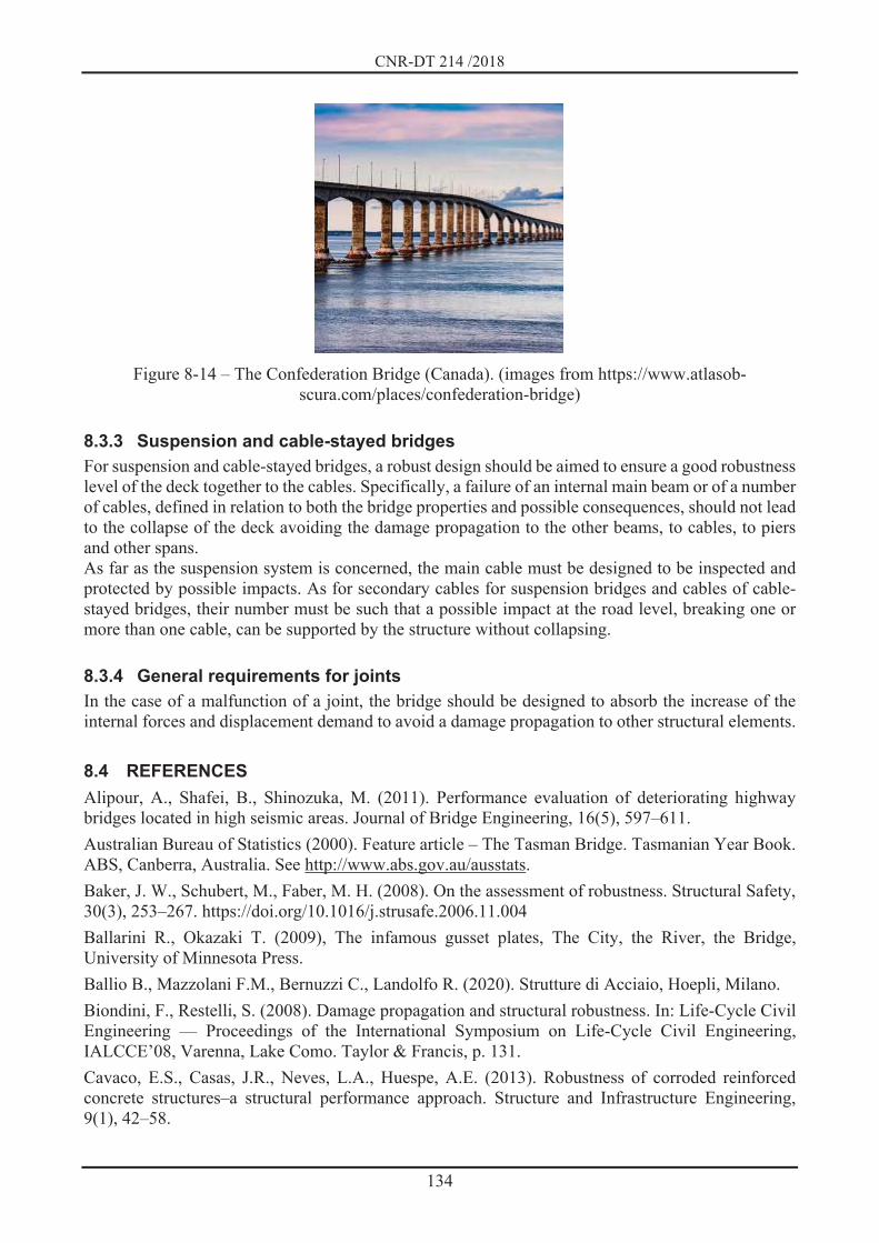
CNR-DT 214 /2018
134
Figure 8-14 – The Confederation Bridge (Canada). (images from https://www.atlasob-
scura.com/places/confederation-bridge)
8.3.3 Suspension and cable-stayed bridges For suspension and cable-stayed bridges, a robust design should be aimed to ensure a good robustness level of the deck together to the cables. Specifically, a failure of an internal main beam or of a number of cables, defined in relation to both the bridge properties and possible consequences, should not lead to the collapse of the deck avoiding the damage propagation to the other beams, to cables, to piers and other spans. As far as the suspension system is concerned, the main cable must be designed to be inspected and protected by possible impacts. As for secondary cables for suspension bridges and cables of cable-stayed bridges, their number must be such that a possible impact at the road level, breaking one or more than one cable, can be supported by the structure without collapsing.
8.3.4 General requirements for joints In the case of a malfunction of a joint, the bridge should be designed to absorb the increase of the internal forces and displacement demand to avoid a damage propagation to other structural elements.
8.4 REFERENCES Alipour, A., Shafei, B., Shinozuka, M. (2011). Performance evaluation of deteriorating highway bridges located in high seismic areas. Journal of Bridge Engineering, 16(5), 597–611. Australian Bureau of Statistics (2000). Feature article – The Tasman Bridge. Tasmanian Year Book. ABS, Canberra, Australia. See http://www.abs.gov.au/ausstats. Baker, J. W., Schubert, M., Faber, M. H. (2008). On the assessment of robustness. Structural Safety, 30(3), 253–267. https://doi.org/10.1016/j.strusafe.2006.11.004 Ballarini R., Okazaki T. (2009), The infamous gusset plates, The City, the River, the Bridge, University of Minnesota Press. Ballio B., Mazzolani F.M., Bernuzzi C., Landolfo R. (2020). Strutture di Acciaio, Hoepli, Milano. Biondini, F., Restelli, S. (2008). Damage propagation and structural robustness. In: Life-Cycle Civil Engineering — Proceedings of the International Symposium on Life-Cycle Civil Engineering, IALCCE’08, Varenna, Lake Como. Taylor & Francis, p. 131. Cavaco, E.S., Casas, J.R., Neves, L.A., Huespe, A.E. (2013). Robustness of corroded reinforced concrete structures–a structural performance approach. Structure and Infrastructure Engineering, 9(1), 42–58.
CNR-DT 214 /2018
135
Cavaco, E.S., Neves L.A.C., Casas, J.R. (2018). On the robustness to corrosion in the life-cycle assessment of an existing reinforced concrete bridge. Structure and Infrastructure Engineering, 14(2), 137–150. Di Prisco M., Colombo, M., Martinelli, P., Coronelli, D. (2018). The technical causes of the collapse of Annone overpass on SS. 36, in Italian Concrete Days 2018, Lecco, Italy, pp. 1-16. Echevarri, A., Zaghi, A.E., Christenson, R., Accorsi, M. (2016). CFFT bridge columns for multihazard resilience. Journal of Structural Engineering, 142(8). JCSS Joint Committee for Structural Safety. (2001). JCSS Probabilistic Model Code 2001 Liao M., Okazaki T. (2009), A computational study of the I-35W Bridge collapse, Center for Transportation studies, University of Minnesota, http://cts-d8resmod-prd.oit.umn.edu:8080/pdf/cts-09-29.pdf. Mondorf P.E. (2006). Concrete Bridges. Taylor & Francis, London, UK. Rackwitz, R. (2000). Optimization – the basis of code-making and reliability verification. Structural Safety 22(1): 27–60. Radowitz B., Schubert M., Faber M. H. (2008). Robustness of Externally and Internally Post-Tensioned Bridges, Beton und Stahlbetonbau 103, Special Edition. Scheer J. (2000, 2001). Versagen von Bauwerken. Ernst & John, Berlin, Germany, vol. 1, 2000; vol. 2, 2001. Starossek U. (1999). Progressive collapse study of a multi-span bridge, Structural Engineering International, 9:2, 121-125, DOI: 10.2749/101686699780621127 Starossek U. (2018). Progressive Collapse of Structures. ICE Publishing, London, UK. Starossek, U. (2007). Disproportionate collapse: a pragmatic approach, Structures & Buildings, Vol. 160, No. SB6, pp. 317–325. Starossek, U., Haberland M. (2012). Robustness of structures, International Journal of Lifecycle Performance Engineering, Vol. 1, No. 1, pp. 3 21.

CNR-DT 214 /2018
136
9 EXAMPLES AND CASE STUDIES
9.1 MEMBRANE EFFECTS IN CONTINUOUS SLABS IN THE PRESENCE OF ACCIDENTAL ACTIONS
Some parametric studies have been performed recently to evaluate the compressive membrane actions effects on the resistance of continuous slabs under accidental actions, considering the variation of the following parameters:
1. Dimension b of the supporting columns: 130 mm, 195 mm, 260 mm, 325 mm, 390 mm. 2. Slab thickness: 23 cm, 25 cm, 27 cm, 29 cm, 31 cm. 3. Span L between adjacent columns: 4 m, 5 m, 6 m, 7 m, 8m. 4. Percentage of steel reinforcement at the column section (extrados) ( hogg): 1,5 %, 0,75 %,
0,375% and ratio with the percentage in the slab span center ( sagg). The presented case study is not related to a column loss scenario but to an assessment of the maximum resistance of continuous slabs by considering membrane actions. In order to evaluate the effect of the redistribution of internal actions and membrane forces, the resistance of an isolated slab was compared with the resistance of continuous slabs (Belletti et al., 2018). Multi-layer shell elements were used for the modeling and both geometric and mechanical nonlinearities were considered (Figure 9-1a and b). Mechanical nonlinearity is assessed through the PARC_CL 2.0 crack model implemented in the finite element program Abaqus (Belletti et al., 2017). Continuous slabs (Self confined - SC) and corresponding isolated slabs (ISO) having edge length equal to 0.22 L were analysed. In addition, the presence of concrete shrinkage was also considered, in order to investigate if cracking induced by shrinkage can reduce the compressive membrane ac-tions. Table 9-1 shows the mechanical properties of materials adopted for the modelling.
(c) (d) Figure 9-1 – RC concrete slab analysed with different boundary conditions: a) continuous slab; b)
isolated slab; c) punching shear (V) and slab rotation ( ); d) control perimeter at 0.5d from the edge of the column.

CNR-DT 214 /2018
137
Table 9-1 – Mean mechanical properties for concrete and steel reinforcement
fcm [MPa] Ec [MPa] fy [MPa] Es [MPa] 35 32643 520 200000
Figure 9-2 shows the load – rotation (i.e. V- , as defined in Figure 9-1c) curves obtained by the parametric analysis for the intermediate case (L = 6m, b = 260mm, h = 250mm), carried out by varying the steel reinforcement ratio. Dashed curves indicate the results where the effect of shrinkage is taken into account. It can be observed that the effect of the redistribution of internal actions and of the membrane forces is greater in the case of plates with a lower percentage of reinforcement at the extrados of the column due to the greater redistribution of internal actions and the greater stiffness difference between slab zones with and without cracking. It is also noted that shrinkage induces a decrease in strength, albeit limited, for all case studies.
Figure 9-2 – Membrane behavior in RC slabs, load – rotation curves V – obtained with different numerical models and considering the effect of concrete shrinkage; continuous and isolated slabs
The load – rotation curves in Figure 9-2 were obtained through multi-layer shell elements able to model the flexural behavior, but not the shear failure, in the slab thickness. The punching shear failure was evaluated according to Model Code 2010 (fib, 2013), based on Critical Shear Crack Theory (Muttoni, 2008). The following Eq. (9.1) and Eq. (9.2) give, respectively, the mean punching shear-strength and the design values, as a function of the compression strength of concrete (fcm and fck), of the slab thickness h (through the shear height dv), of side dimension b of supporting columns (and of control perimeter b0 set at 0,5d from the column section side, see Figure 9-2), of aggregate dimension dg and dg0 (set equal to 16 mm), i.e.: 341 15 (9.1)
1.5 0.9 (9.2)
Figure 9-3 highlights that the shrinkage of the concrete leads to a reduction of the membrane forces with a consequent decrease in the flexural and punching resistance of the slab.

CNR-DT 214 /2018
138
Figure 9-3 – Effect of shrinkage on membrane actions in RC slab
9.2 CLT-WALL BUILDINGS: PRESCRIPTIONS FOR ROBUSTNESS With reference to multi-store buildings made of Cross-Laminated Timber panels (CLT, see Section 6.5.4.1), in case of a Vierendeel beam resistant mechanism and in the absence of more accurate eval-uations, the minimum dimensions of the different panels that compose the wall systems in order to ensure a robust configuration for different wall typologies are given in this Section. The analyses necessary to evaluate the minimum dimensions have been conducted with reference to the case of a monolithic-panel wall (Figure 6-49a) and can be extended to the multi-panel configura-tion (Figure 6-49b) upon the adoption of appropriate connections between the individual elements that compose the wall system. These minimum dimensions have been obtained by means of an extensive parametric analysis carried out on different configurations: varying the number of openings, the length and the thickness of the wall and the strength class of timber. In particular, the different elements constituting the wall were verified for shear and bending (combined with compression or tension) using the partial factor for the material properties m = 1 (accidental actions) and the strength modification factor kmod = 1 (instantaneous loads). Figure 9-4 shows the schematization of the geometry of the walls considered in the parametric anal-yses. In particular:
the arrangement of the window openings is symmetrical; the dimensions of the coupling beams below and above the openings are related through the
parameter the width of the edge vertical element was considered double of that of the internal ones.
The analyses were conducted assuming the parameters summarized in Table 9-2. As an example, for the case of a 3-layer wall, with 3 openings and a load of 10 kN/m, a length of 7 m, thickness 100 mm, strength class of the layers C16 and =1, Figure 9-5 shows the configuration for which the strength limit is attained in at least one element and which therefore represents the “limit geometric configuration” characterized by the minimum value of the width B of the vertical element compatible with the wall length L=7 m. Figure 9-6 shows the results in terms of deflections and stress diagrams for this configuration and the red marker denotes which verification is not fulfilled (in this case, combined compressive and bending moment) and in which section the strength limit is reached.

CNR-DT 214 /2018
139
a) b)
Figure 9-4 – Schematization of the analysed walls: a) wall geometry; b) openings
Table 9-2 – Parameters used in parametric analysis parameter Values adopted in the analyses A, A Coupling beam size Four different configurations: A=50cm =0.3*, 1, 2, 3 H Wall height constant L Distance between supports Variable between 4 m and 12 m s Wall thickness 100 mm and 120 mm Panel layering 3 or 5 layers with homogeneous thickness Layers strength C16 and C24 accordingly to EN 338:2209 Opening configurations 3 – 4 – 5 openings Design loads 10 kN/m – 15 kN/m – 20 kN/m * case with door window
Figure 9-5 – 3-layer wall limit geometric configuration, 3 openings, load 10 kN/m, length 7 m,
thickness 100 mm, strength class of the layers C16 and =1

CNR-DT 214 /2018
140
Figure 9-6 – Stress resultants and deflection for the 3-layer wall, 3 openings, load 10 kN/m, length 7
m, thickness 100 mm, strength class of the layers C16 and =1 With this procedure all configurations summarized in Table 9-2 were analysed and the limit geometric configurations were evaluated in all cases. For the 3-layer wall panels with 3 openings and a load of 10 kN/m, Figure 9-7 shows the relationship between the minimum thickness of the vertical columns and the maximum length of the Vierendeel beam for the different opening geometries (A=50 cm and =0.3, 1, 2, 3 where the case =0.3 refers to the presence of 3 French windows), varying the timber strength class (C16 and C24) and the wall thickness (100 mm and 120 mm). In order to facilitate the use by designers, the results of the analyses are also summarized in tabular form, Table 9-3.
Deformed configuration – L = 7000 Axial Force – L = 7000 mm
Shear Force – L = 7000 mm Bending Moment – L = 7000 mm

CNR-DT 214 /2018
141
a)
b)
Figure 9-7 – Relationship between the thickness B of the vertical posts and the maximum length L of the 3-layer wall and load 10 kN/m for different strength classes of the layers and different
openings configurations: a) wall thickness 100 mm; b) wall thickness 120 mm

CNR-DT 214 /2018
142
Table 9-3 – Minimum size B of the vertical post of the 3-layer wall and load 10 kN/m
9.3 REFERENCES Belletti, B., Scolari, M., Vecchi, F. (2017). PARC_CL 2.0 crack model for NLFEA of reinforced concrete structures under cyclic loadings. Computers and Structures; 191:165-179. Belletti B., Muttoni A., Ravasini S., Vecchi F. (2018). Parametric analysis on punching shear resistance of reinforced concrete continuous slabs. Magazine of Concrete Research; https://doi.org/10.1680/jmacr.18.00123 fib – International federation for structural concrete. fib model code for concrete structures 2010. Ernst & Sohn; 2013. Muttoni A. (2008). Punching shear strength of reinforced concrete slabs without transverse reinforcement. ACI Structural Journal; 105:440–50.
t2 120 253 167 82 36 40 28 26 20t1 = 100 262 250 118 67 60 35 34 21t2 = 120 262 182 92 46 42 30 29 20t1 = 100 270 270 131 75 65 37 37 24t2 = 120 270 199 105 54 47 32 31 20t1 = 100 278 278 144 86 71 39 39 26t2 = 120 278 218 118 62 54 34 33 21t1 = 100 287 287 158 99 77 41 41 28t2 = 120 287 244 131 69 59 36 35 23t1 = 100 295 295 171 112 82 43 44 30t2 = 120 295 291 144 81 64 38 37 25t1 = 100 303 303 186 124 88 49 46 32t2 = 120 303 303 157 93 69 40 39 27t1 = 100 312 312 203 138 94 54 48 34t2 = 120 312 312 171 106 74 41 41 28t1 = 100 320 320 220 151 101 58 53 36t2 = 120 320 320 184 118 80 43 44 30t1 = 100 328 328 237 164 107 63 58 38t2 = 120 328 328 197 131 85 46 46 32t1 = 100 337 337 253 178 114 68 62 40t2 = 120 337 337 213 144 91 50 48 34t1 = 100 345 345 270 191 121 73 67 42t2 = 120 345 345 230 158 97 55 50 36t1 = 100 353 353 288 205 128 78 72 43t2 = 120 353 353 247 171 103 59 53 37t1 = 100 362 362 305 218 135 83 76 45t2 = 120 362 362 264 184 109 63 58 39t1 = 100 370 370 323 235 143 89 82 47t2 = 120 370 370 281 198 115 68 62 41t1 = 100 378 378 378 252 162 94 87 49t2 = 120 378 378 298 211 122 72 66 42t1 = 100 387 387 387 269 186 101 92 52t2 = 120 387 387 315 225 129 77 71 44t1 = 100 395 395 395 287 209 106 98 55t2 = 120 395 395 332 239 135 82 75 46
8
8.25
8.5
8.75
9
9.25
9.5
9.75
10
11.5
11.75
12
10.25
10.5
10.75
11
11.25
3 strati omogenei = 0.3 = 1 = 2 = 3C16 C24 A1 = 50 A1 = 50 A1 = 50 A1 = 50L (m) t (mm) A2 = *A1 A2 = *A1 A2 = *A1 A2 = *A1
3 strati omogenei = 0.3 = 1 = 2 = 3C16 C24 A1 = 50 A1 = 50 A1 = 50 A1 = 50L (m) t (mm) A2 = *A1 A2 = *A1 A2 = *A1 A2 = *A1
t1 = 100 48 20 20 20 20 20 20 20t2 = 120 36 20 20 20 20 20 20 20t1 = 100 58 33 20 20 20 20 20 20t2 = 120 47 20 20 20 20 20 20 20t1 = 100 69 42 24 20 20 20 20 20t2 = 120 56 20 20 20 20 20 20 20t1 = 100 80 51 27 20 20 20 20 20t2 = 120 66 39 23 16 20 20 20 20t1 = 100 92 60 29 20 20 20 20 20t2 = 120 77 47 25 20 20 20 20 20t1 = 100 105 70 32 23 20 20 20 20t2 = 120 87 56 28 20 20 20 20 20t1 = 100 118 80 34 25 20 20 20 20t2 = 120 99 64 30 21 20 20 20 20t1 = 100 132 91 36 27 24 17 20 20t2 = 120 111 74 32 23 20 20 20 20t1 = 100 148 102 39 29 28 20 20 20t2 = 120 124 84 34 25 21 20 20 20t1 = 100 166 114 52 31 31 20 20 20t2 = 120 137 94 35 27 25 20 20 20t1 = 100 192 126 61 32 34 20 20 20t2 = 120 152 104 38 29 28 20 20 20t1 = 100 214 139 69 34 36 24 21 20t2 = 120 169 115 51 30 31 20 20 20t1 = 100 228 153 77 35 39 26 24 20t2 = 120 189 127 59 31 33 20 20 20t1 = 100 237 168 85 42 41 29 27 20t2 = 120 222 140 67 33 35 23 21 20t1 = 100 245 186 93 52 47 31 30 20t2 = 120 245 152 74 35 38 26 24 20t1 = 100 253 207 105 60 54 33 32 20t2 = 120 253 167 82 36 40 28 26 20
4
4.25
4.5
4.75
5
5.25
5.5
5.75
6
6.25
6.5
6.75
7
7.25
7.5
7.75

CNR-DT 214 /2018
143
10 APPENDIX A: A SIMPLIFIED APPROACH TO EVALUATE THE LOAD-CARRYING CAPACITY OF REINFORCED CONCRETE SLABS CONSIDERING TENSILE MEMBRANE ACTION
10.1 INTRODUCTION In recent years, several experimental tests have been conducted on one-dimensional and bi-dimensional RC elements under catenary/tensile membrane action simulating the sudden removal of a support (Gouverneur et al., 2013; Galmarini et al., 2015, among the others). The use of numerical models, such as the finite element method, to simulate the structural behavior and to determine the ultimate load-carrying capacity of reinforced concrete (RC) slabs can provide accurate results since it incorporates both geometric and material nonlinearities. Its use for analysing slabs in a highly nonlinear region is complex and rarely adopted in the engineering design process (Botte et al., 2015; Belletti et al., 2016; Russel et al., 2018). In this context, analytical simplified methods as the one presented in this appendix are particularly attractive to conduct preliminary alternative load path analyses. In this appendix, a design method for the evaluation of the tensile membrane contribution to the ultimate bearing capacity of RC slabs is briefly presented. The motivation of the approach derives from the fact that, in recent years, investigations on the behavior and modelling of laterally restrained and unrestrained RC slabs have been intensified due to the reserve of bearing capacity provided by the tensile membrane action. Of particular relevance in this context is the case of the sudden removal of one or more columns and/or wall. The approach has been developed in the framework of the strip method and analyses the tensile membrane effect. Two failure criteria are accounted for: the maximum slab strip elongation and the maximum rotation of the structure at the supports. The basic idea consists in the use of a simple model for the deformed shape at collapse (catenary or parabolic shape functions). A complete description of the method can be found in Colombo et al. (2020) where the method implementation and its validation are also discussed.
10.2 REVIEW OF THE STRIP METHOD IN A LARGE DISPLACEMENT CONFIGURATION
In the framework of the Static Method, Hillerborg (1956, 1975) developed a simple design method (named strip method) to calculate the bending moments in a slab. It gives a lower bound equilibrate solution of the moments and, as such, a safe estimation of the capacity of the slab in flexure. The basic equilibrium condition for a slab is given by the following equation: 2 , (10.1)
where mx and my are the bending moments about axes parallel to the edges, while mxy is the twisting moment about axes perpendicular to the edges. There are infinite moments fields that satisfy equation (10.1). If reinforcement bars are provided along x and y directions, one possible equilibrated solution of Eq. (1) is obtained by assuming mxy = 0. From a mechanical point of view, neglecting twisting moment in a cracked slab means to ignore (i) the twisting strength in the compressed zone, (ii) the aggregate interlock and (iii) the bar dowel action, thus assuming that the slab behaves like a set of strips arranged in the directions x and y, each subjected to bending and shear. With this in mind, the total load q can be divided between the load carried in x direction ( ) and that carried in y direction (1 ), where the coefficient ranges between 0 and 1. Equation (10.1) with 0 gives rise to the following two equations:

CNR-DT 214 /2018
144
,1 , (10.2)
where . The bending moments mx and my are systematically overestimated since the twisting of the strips due to mxy is ignored. The distribution of the load q between the strips as well as the choice of the strips is entirely arbitrary. A simple way to determine qx and qy (or equivalently ) is to only consider the two central strips, in x and y directions, and impose the compatibility of deflections at the center of the strips as schematically shown in Figure 10-1. This method is known as Rankine-Grashoff’s method. The equilibrium condition of the slab, equation (10.1), can alternatively be written in a deformed configuration, in which a membrane regime is established. In this case, it is possible, for simplicity, to neglect the bending contribution in the equilibrium equations. Still adopting the strip method, and indicating the specific membrane forces with Nx and Ny, a new equilibrium configuration can be written: ,1 , (10.3)
where and represent the rotations around y and x axes. The first term in equation (10.3) is related to the amplitude variation of the tensile membrane force, while the second term is related to the variation in direction of the tensile membrane force. Equations (10.2) and (10.3) are formally similar and show two different ways of supporting the load, in flexural regime or, alternatively, in membrane regime.
Figure 10-1 – Example of simply-supported rectangular slab analysed with Rankine – Grashoff’s
method
10.3 THEORETICAL FORMULATION FOR SLAB STRIP In a large displacement configuration, the load-carrying capacity of the slab is mainly guaranteed by the tensile membrane action. The results obtained in Section 10.2, see equation (10.3), allow the study of the membrane behavior of the slab as strips separately acting in x and y directions. Figure10-2

CNR-DT 214 /2018
145
shows a flat slab in which the stiffness of the strip in the x direction is prevalent, because the strip in the y direction ends on an edge frame, which is not able to ensure the stiffness necessary for the establishment of a membrane behavior in both directions. The tensile membrane behavior of one–dimensional (1D) strip is based on the following assumptions:
a) the concrete is fully cracked throughout its thickness and hence cannot carry any load; b) all the reinforcement bars are stretched and yielded on average; c) the force in the reinforcement bars (Z) per unit width is considered constant throughout its
length. It is worth noting that assumptions a) and b) imply that the flexural capacity of the slab is equal to zero. Assumption c), in the case of a fully tensile membrane behavior, is equivalent to impose that: 1
(10.4)
where L0 is the initial (undeformed) length of the strip.
Figure10-2 – Slab on a rectangular grid of column in case of a sudden column loss (in grey the area
subjected to strong tensile membrane action) The tensile membrane behavior of a 1D slab strip is derived using the Principle of Virtual Work (PVW) as sufficient condition of equilibrium (Figure 10-3). Imposing the following identity:
(10.5)
for all the virtual kinematics and , is equivalent to impose the equilibrium condition for the slab strip. In equation (10.5), is the virtual vertical deflection, while b represents the width of the strip.
is the virtual infinitesimal elongation of the strip calculated as the difference between the current (L+ ) and the previous (L) deformation stages. The tensile membrane force associated to the yielding of the bars is equal to: (10.6)
where fy is the yielding strength of the bar and , are, respectively, the bottom and top longitudinal reinforcement bar area per unit width. The resultant tension force is always applied to the center of gravity of the overall reinforcement.
x
y
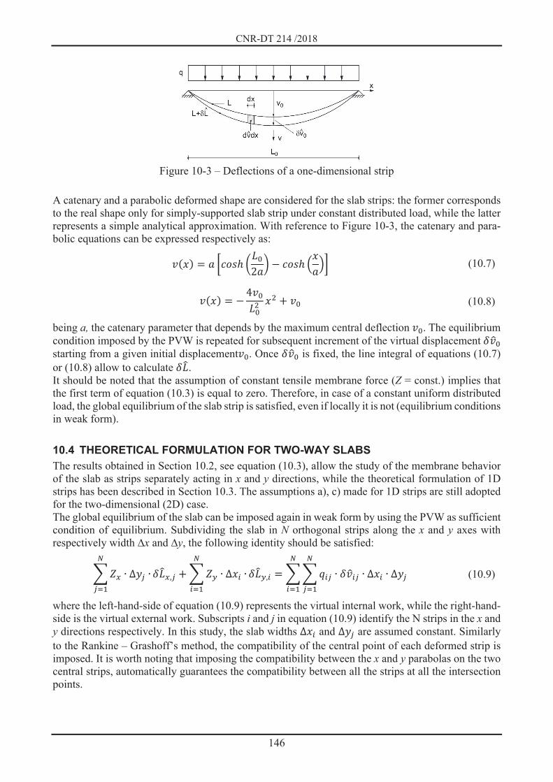
CNR-DT 214 /2018
146
Figure 10-3 – Deflections of a one-dimensional strip
A catenary and a parabolic deformed shape are considered for the slab strips: the former corresponds to the real shape only for simply-supported slab strip under constant distributed load, while the latter represents a simple analytical approximation. With reference to Figure 10-3, the catenary and para-bolic equations can be expressed respectively as:
2 (10.7) 4 (10.8)
being a, the catenary parameter that depends by the maximum central deflection . The equilibrium condition imposed by the PVW is repeated for subsequent increment of the virtual displacement starting from a given initial displacement . Once is fixed, the line integral of equations (10.7) or (10.8) allow to calculate . It should be noted that the assumption of constant tensile membrane force (Z = const.) implies that the first term of equation (10.3) is equal to zero. Therefore, in case of a constant uniform distributed load, the global equilibrium of the slab strip is satisfied, even if locally it is not (equilibrium conditions in weak form).
10.4 THEORETICAL FORMULATION FOR TWO-WAY SLABS The results obtained in Section 10.2, see equation (10.3), allow the study of the membrane behavior of the slab as strips separately acting in x and y directions, while the theoretical formulation of 1D strips has been described in Section 10.3. The assumptions a), c) made for 1D strips are still adopted for the two-dimensional (2D) case. The global equilibrium of the slab can be imposed again in weak form by using the PVW as sufficient condition of equilibrium. Subdividing the slab in N orthogonal strips along the x and y axes with respectively width x and y, the following identity should be satisfied:
, , (10.9)
where the left-hand-side of equation (10.9) represents the virtual internal work, while the right-hand-side is the virtual external work. Subscripts i and j in equation (10.9) identify the N strips in the x and y directions respectively. In this study, the slab widths and are assumed constant. Similarly to the Rankine – Grashoff’s method, the compatibility of the central point of each deformed strip is imposed. It is worth noting that imposing the compatibility between the x and y parabolas on the two central strips, automatically guarantees the compatibility between all the strips at all the intersection points.

CNR-DT 214 /2018
147
10.5 FAILURE CRITERIA In the following sub-sections, two failure criteria are presented: the maximum slab strip elongation and the maximum rotation of the structure at the supports. It is worth noting that the method aims at defining the ultimate bearing capacity of two-way slabs when the failure is governed by tensile membrane (i.e. tension failure).
10.5.1 Evaluation of the maximum elongation The tensile membrane contribution is limited by the ductility of the solution investigated. A first failure criterion is related to the maximum elongation of the slab portion stretched by the membrane action (correlated to the axial ductility). With reference to Figure 10-3, the elongation is calculated as:
(10.10)
and it is here determined evaluating the crack widths, which may arise in the stretched part of the slab, by assuming that the most open crack reaches its maximum crack opening. The number of cracks (ncr), when steel reinforcement is embedded into the concrete matrix, is computed by dividing the initial length L0 by the maximum crack distance (2×ls,max) where ls,max is the steel to concrete slip length, according to fib Model Code 2010 (MC2010, fib, 2013). The maximum crack opening that can be reached is computed according to the indication reported in fib Bulletin 63 (fib, 2012) by using the following equation: , (10.11)
where wy = 2×ls,max×fy/Es is the crack width when yielding starts (with fy the yielding strength of the bar), su is the reinforcement strain at the end of the plastic branch and lt,pl is the maximum extension of the plastic zone along the bar, which can be computed as:
, , 4 (10.12)
where ft is the tensile strength of the bar at failure, is the bar diameter and , 0.68 is the average bond stress in the plastic zone in case of good bond conditions (units in MPa) (fib, 2012). In the definition of the load bearing capacity of the slab, the tensile membrane contribution of the steel reinforcement is effective until the elongation L of the stretched portion is smaller than the maximum elongation Lmax, that corresponds to the situation in which the maximum crack opening reaches the value of wu. The strain within the catenary shape is very well approximated by a parabolic shape; for this reason, the same parabolic variation was assumed for crack opening w(x), whose value ranges from wy at mid-span to wu at the supports. By means of this assumption, it is possible to compute and then add all the crack width values along the strip (wi in Figure 10-4) and define the maximum elongation Lmax.

CNR-DT 214 /2018
148
Figure 10-4 – Definition of the maximum elongation and rotation.
10.5.2 Evaluation of the maximum rotation A second failure criterion that can be adopted to limit the tensile membrane contribution is related to the maximum rotation. This criterion is associated with a local failure, typically located at the support/clamping positions, where the rotation demand is maximum. In this study, it is assumed that the maximum rotation is governed by the flexure, assuming an appropriate shear reinforcement at the supports. The maximum rotation is calculated integrating the maximum curvature along the plastic hinge length lp:
(10.13)
having assumed a plastic hinge length lp equal to the maximum crack spacing 2×ls,max.
10.6 REFERENCES Belletti B., Damoni C., Cervenka V., Hendriks, M.A.N. (2016). Catenary action effects on the structural robustness assessment of RC slab strips subjected to shear and tensile forces, Structural Concrete; 17(6): 1003–1016. Botte W., Gouverneur D., Caspeele R., Taerwe L. (2015). Influence of design parameters on tensile membrane action in reinforced concrete slabs, Struct. Eng. Int.; 25(1): 50–60. Colombo M., Martinelli P., di Prisco M. (2020). A design approach to evaluate the load-carrying capacity of RC slabs considering tensile membrane action, Structural Engineering International, DOI:10.1080/10168664.2020.1747957. fib – International federation for structural concrete. fib model code for concrete structures 2010. Ernst & Sohn; 2013. fib bulletin 63, (2012). Design of precast concrete structures against accidental actions. Fédération Internationale du béton, Lausanne (CH), 78 pages, ISBN 978-2-88394-103-8.