Guide for ACS-BRK Brake Units (English - pdf - Manual) - ABB · PDF fileiii Safety Warning!...
32
ACS-BRK Brake Units Installation and Start-up Guide
Transcript of Guide for ACS-BRK Brake Units (English - pdf - Manual) - ABB · PDF fileiii Safety Warning!...
ACS-BRK Brake Units
Installation andStart-up Guide

© 2002 ABB Oy.
3AFY 61514309 REV CEN
Effective: 16.09.2002
Installation and Start-up Guide
ACS-BRKBrake Units

iii
Safety
Warning! All electrical installation and maintenance work on the ACS-BRK brake units should be carried out by qualified electricians.
Warning! Do not attempt any work on a powered ACS-BRK. After disconnecting the mains from the feeding frequency converter which brake unit is connected to, always wait 5 minutes to allow intermediate circuit capacitors to become discharged before working on the ACS-BRK brake unit. Always check (with voltage indicating instrument) that the ACS-BRK is unpowered before beginning the work.
Warning! Never attempt to repair a broken unit; always contact the supplier for replacement.
Warning! In normal heavy loading, maximum temperature of the wall attachment reaches +90°C. Temperature of the body and the cover may be higher. In heavy overloading cases, temperature of the wall attachment may be higher.
Note! For more technical information, contact your local supplier.
Because of the variety of uses for this equipment and because of the differences between this solid-state equipment and electromechanical equipment, the user of and those responsible for applying this equipment must satisfy themselves as to the acceptability of each application and use of the equipment. In no event will ABB be responsible or liable for indirect or consequential damages resulting from the use or application of this equipment.

iv
v
Table of Contents
Safety. . . . . . . . . . . . . . . . . . . . . . . . . . . . . . . . . . . . . . . . . . . . . . iii
Chapter 1 - About This Manual . . . . . . . . . . . . . . . . . . . . . . . . . . 1
Chapter 2- Product Overview . . . . . . . . . . . . . . . . . . . . . . . . . . . 3
Chapter 3 - Technical Details . . . . . . . . . . . . . . . . . . . . . . . . . . . 5Electrical Specifications . . . . . . . . . . . . . . . . . . . . . . . . . . 5Environmental Specification . . . . . . . . . . . . . . . . . . . . . . . 5Mounting. . . . . . . . . . . . . . . . . . . . . . . . . . . . . . . . . . . . . . 5Ventilation. . . . . . . . . . . . . . . . . . . . . . . . . . . . . . . . . . . . . 6Mechanical Specification . . . . . . . . . . . . . . . . . . . . . . . . . 7
Chapter 4 - Electrical Installation . . . . . . . . . . . . . . . . . . . . . . . . . 9
Chapter 5 - Mandatory Installation InstructionsAccording to the EMC Directive. . . . . . . . . . . . . . . . . . . . . . . . . . 13
Chapter 6 - Selection of Brake Unit . . . . . . . . . . . . . . . . . . . . . . . 15A. Normal and Heavy Duty Use . . . . . . . . . . . . . . . . . . . . 16B. Choosing the Correct ACS-BRKfor Repetitive Peak Load Duty . . . . . . . . . . . . . . . . . . . . . 17C. Choosing the Correct ACS-BRK for Single Peak Duty. . . . . . . . . . . . . . . . . . . . . . . . . . . . . 20

vi
1
AB
OU
T T
HIS
MA
NU
AL
Chapter 1 – About This ManualThis manual provides you with the information necessary to select the correct ACS-BRK brake unit and to install it.
Safety instructions are at the beginning of the manual. Read them carefully and exercise appropriate care when working with the unit.
Manual Contents:
Chapter 2 Product Overview
Chapter 3 Technical Details
Chapter 4 Electrical Installation
Chapter 5 Mandatory Installation Instructions According to the EMC Directive
Chapter 6 Selection of Brake Unit

2

3
PR
OD
UC
T O
VE
RV
IEW
Chapter 2 – Product OverviewWhen the drive application requires rapid or accurate deceleration of the motor, an ACS-BRK braking unit is needed. The braking unit converts the kinetic energy of the motor into thermal energy.
ACS-BRK braking units consist of a braking resistor and control electronics. These brake units can be used with the following ABB frequency converter series for both 200 - 240 V and 380 - 480 V line voltage.
• ACS 100• ACS 140• ACS 400
Each brake unit can be connected to any of the frequency converter listed above. The brake unit is selected according to the required braking power, not according to the rated power of the frequency converter. This guarantees the best price/performance ratio to the customer.
Example:
We have a 400 V drive application. The required continuous braking power is 100 W and the power rating of the frequency converter is 2.2 kW.
The right selection is ACS-BRK-A.

4
5
TE
CH
NIC
AL D
ET
AIL
S
Chapter 3 – Technical Details
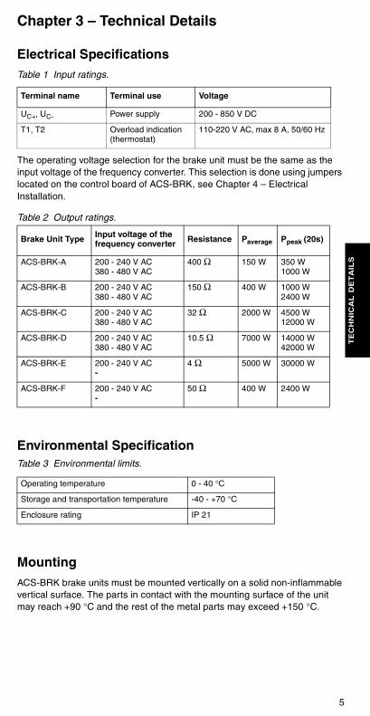
Electrical SpecificationsTable 1 Input ratings.
The operating voltage selection for the brake unit must be the same as the input voltage of the frequency converter. This selection is done using jumpers located on the control board of ACS-BRK, see Chapter 4 – Electrical Installation.
Table 2 Output ratings.
Environmental SpecificationTable 3 Environmental limits.
MountingACS-BRK brake units must be mounted vertically on a solid non-inflammable vertical surface. The parts in contact with the mounting surface of the unit may reach +90 °C and the rest of the metal parts may exceed +150 °C.
Terminal name Terminal use Voltage
UC+, UC- Power supply 200 - 850 V DC
T1, T2 Overload indication(thermostat)
110-220 V AC, max 8 A, 50/60 Hz
Brake Unit Type Input voltage of the frequency converter Resistance Paverage Ppeak (20s)
ACS-BRK-A 200 - 240 V AC380 - 480 V AC
400 Ω 150 W 350 W1000 W
ACS-BRK-B 200 - 240 V AC380 - 480 V AC
150 Ω 400 W 1000 W2400 W
ACS-BRK-C 200 - 240 V AC380 - 480 V AC
32 Ω 2000 W 4500 W12000 W
ACS-BRK-D 200 - 240 V AC380 - 480 V AC
10.5 Ω 7000 W 14000 W42000 W
ACS-BRK-E 200 - 240 V AC-
4 Ω 5000 W 30000 W
ACS-BRK-F 200 - 240 V AC-
50 Ω 400 W 2400 W
Operating temperature 0 - 40 °C
Storage and transportation temperature -40 - +70 °C
Enclosure rating IP 21
6
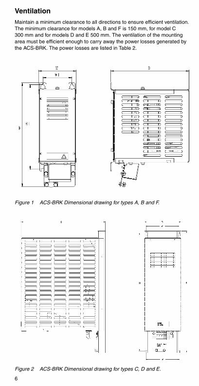
VentilationMaintain a minimum clearance to all directions to ensure efficient ventilation. The minimum clearance for models A, B and F is 150 mm, for model C 300 mm and for models D and E 500 mm. The ventilation of the mounting area must be efficient enough to carry away the power losses generated by the ACS-BRK. The power losses are listed in Table 2.
Figure 1 ACS-BRK Dimensional drawing for types A, B and F.
Figure 2 ACS-BRK Dimensional drawing for types C, D and E.
7
TE
CH
NIC
AL D
ET
AIL
S
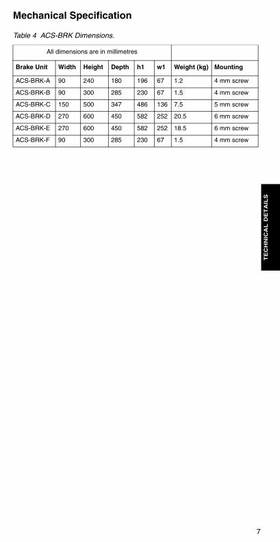
Mechanical Specification
Table 4 ACS-BRK Dimensions.
All dimensions are in millimetres
Brake Unit Width Height Depth h1 w1 Weight (kg) Mounting
ACS-BRK-A 90 240 180 196 67 1.2 4 mm screw
ACS-BRK-B 90 300 285 230 67 1.5 4 mm screw
ACS-BRK-C 150 500 347 486 136 7.5 5 mm screw
ACS-BRK-D 270 600 450 582 252 20.5 6 mm screw
ACS-BRK-E 270 600 450 582 252 18.5 6 mm screw
ACS-BRK-F 90 300 285 230 67 1.5 4 mm screw

8
9
EL
EC
TR
ICA
L IN
ST
AL
LA
TIO
N
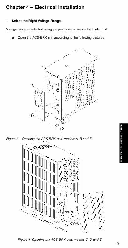
Chapter 4 – Electrical Installation
1 Select the Right Voltage Range
Voltage range is selected using jumpers located inside the brake unit.
A Open the ACS-BRK unit according to the following pictures:
Figure 3 Opening the ACS-BRK unit, models A, B and F.
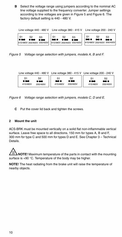
Figure 4 Opening the ACS-BRK unit, models C, D and E.
10
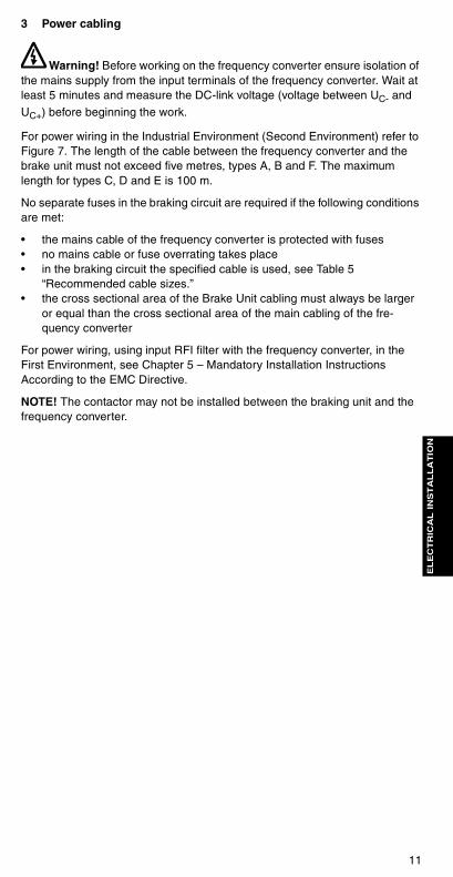
B Select the voltage range using jumpers according to the nominal AC line voltage supplied to the frequency converter. Jumper settings according to line voltages are given in Figure 5 and Figure 6. The factory default setting is 440 - 480 V.
Figure 5 Voltage range selection with jumpers, models A, B and F.
Figure 6 Voltage range selection with jumpers, models C, D and E.
C Put the cover lid back and tighten the screws.
2 Mount the unit
ACS-BRK must be mounted vertically on a solid flat non-inflammable vertical surface. Leave free space to all directions, 150 mm for types A, B and F, 300 mm for type C and 500 mm for types D and E. See Chapter 3 – Technical Details.
NOTE! Maximum temperature of the parts in contact with the mounting surface is +90 °C. Temperature of the body may be higher.
NOTE! The heat radiating from the brake unit will raise the temperature of nearby objects.
Line voltage 200 - 240 V
S1 S2 S3
415/480V 200/400V 200/400V
S1 S2 S3
415/480V 200/400V 200/400V
S1 S2 S3
415/480V 200/400V 200/400V
Line voltage 380 - 415 VLine voltage 440 - 480 V
S1 S2
415/480V 200/400V
S1 S2
415/480V 200/400V
S1 S2
415/480V 200/400V
Line voltage 440 - 480 V Line voltage 380 - 415 V Line voltage 200 - 240 V
11
EL
EC
TR
ICA
L IN
ST
AL
LA
TIO
N
3 Power cabling
Warning! Before working on the frequency converter ensure isolation of the mains supply from the input terminals of the frequency converter. Wait at least 5 minutes and measure the DC-link voltage (voltage between UC- and
UC+) before beginning the work.
For power wiring in the Industrial Environment (Second Environment) refer to Figure 7. The length of the cable between the frequency converter and the brake unit must not exceed five metres, types A, B and F. The maximum length for types C, D and E is 100 m.
No separate fuses in the braking circuit are required if the following conditions are met:
• the mains cable of the frequency converter is protected with fuses• no mains cable or fuse overrating takes place• in the braking circuit the specified cable is used, see Table 5
“Recommended cable sizes.” • the cross sectional area of the Brake Unit cabling must always be larger
or equal than the cross sectional area of the main cabling of the fre-quency converter
For power wiring, using input RFI filter with the frequency converter, in the First Environment, see Chapter 5 – Mandatory Installation Instructions According to the EMC Directive.
NOTE! The contactor may not be installed between the braking unit and the frequency converter.
12
4 Protection of the brake unit
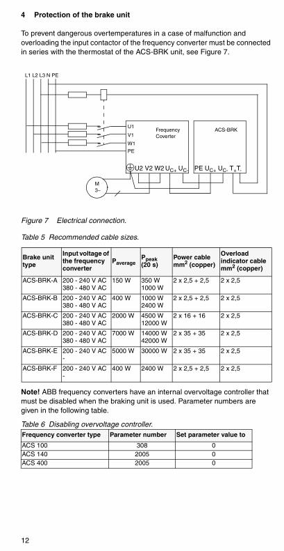
To prevent dangerous overtemperatures in a case of malfunction and overloading the input contactor of the frequency converter must be connected in series with the thermostat of the ACS-BRK unit, see Figure 7.
Figure 7 Electrical connection.
Table 5 Recommended cable sizes.
Note! ABB frequency converters have an internal overvoltage controller that must be disabled when the braking unit is used. Parameter numbers are given in the following table.
Table 6 Disabling overvoltage controller.
Brake unit type
Input voltage of the frequency converter
PaveragePpeak(20 s)
Power cable mm2 (copper)
Overload indicator cable mm2 (copper)
ACS-BRK-A 200 - 240 V AC380 - 480 V AC
150 W 350 W1000 W
2 x 2,5 + 2,5 2 x 2,5
ACS-BRK-B 200 - 240 V AC380 - 480 V AC
400 W 1000 W2400 W
2 x 2,5 + 2,5 2 x 2,5
ACS-BRK-C 200 - 240 V AC380 - 480 V AC
2000 W 4500 W12000 W
2 x 16 + 16 2 x 2,5
ACS-BRK-D 200 - 240 V AC380 - 480 V AC
7000 W 14000 W42000 W
2 x 35 + 35 2 x 2,5
ACS-BRK-E 200 - 240 V AC-
5000 W 30000 W 2 x 35 + 35 2 x 2,5
ACS-BRK-F 200 - 240 V AC-
400 W 2400 W 2 x 2,5 + 2,5 2 x 2,5
Frequency converter type Parameter number Set parameter value to
ACS 100 308 0 ACS 140 2005 0ACS 400 2005 0
U2 V2 W2 PE UC+ UC- T+T-UC+ UC-
L1 L2 L3 N PE
U1
V1
W1
PE
FrequencyCoverter
ACS-BRK
M3~
13
WIR
ING
IN
ST
RU
CT
ION
S
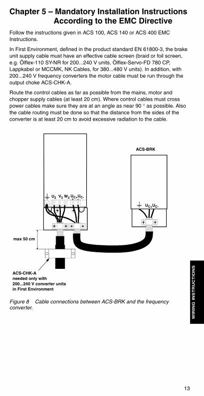
Chapter 5 – Mandatory Installation Instructions According to the EMC Directive
Follow the instructions given in ACS 100, ACS 140 or ACS 400 EMC Instructions.
In First Environment, defined in the product standard EN 61800-3, the brake unit supply cable must have an effective cable screen (braid or foil screen, e.g. Ölflex-110 SY-NR for 200...240 V units, Ölflex-Servo-FD 780 CP, Lappkabel or MCCMK, NK Cables, for 380...480 V units). In addition, with 200...240 V frequency converters the motor cable must be run through the output choke ACS-CHK-A.
Route the control cables as far as possible from the mains, motor and chopper supply cables (at least 20 cm). Where control cables must cross power cables make sure they are at an angle as near 90 ° as possible. Also the cable routing must be done so that the distance from the sides of the converter is at least 20 cm to avoid excessive radiation to the cable.
Figure 8 Cable connections between ACS-BRK and the frequency converter.
U2 V2 W2 UC+UC-
UC+UC-
ACS-BRK
max 50 cm
ACS-CHK-Aneeded only with 200...240 V converter units in First Environment

14
15
SE
LE
CT
ION
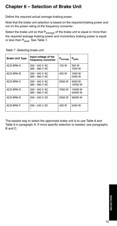
Chapter 6 – Selection of Brake Unit
Define the required actual average braking power.
Note that the brake unit selection is based on the required braking power and not on the power rating of the frequency converter.
Select the brake unit so that Paverage of the brake unit is equal or more than
the required average braking power and momentary braking power is equal or less than Ppeak. See Table 7.
Table 7 Selecting brake unit.
The easiest way to select the approriate brake unit is to use Table 8 and Table 9 in paragraph A. If more specific selection is needed, see paragraphs B and C.
Brake Unit Type Input voltage of the frequency converter Paverage Ppeak
ACS-BRK-A 200 - 240 V AC380 - 480 V AC
150 W 350 W1000 W
ACS-BRK-B 200 - 240 V AC380 - 480 V AC
400 W 1000 W2400 W
ACS-BRK-C 200 - 240 V AC380 - 480 V AC
2000 W 4500 W12000 W
ACS-BRK-D 200 - 240 V AC380 - 480 V AC
7000 W 14000 W42000 W
ACS-BRK-E 200 - 240 V AC-
5000 W 30000 W
ACS-BRK-F 200 - 240 V AC-
400 W 2400 W
16
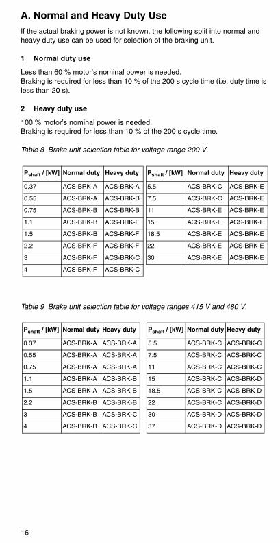
A. Normal and Heavy Duty UseIf the actual braking power is not known, the following split into normal and heavy duty use can be used for selection of the braking unit.
1 Normal duty use
Less than 60 % motor’s nominal power is needed.Braking is required for less than 10 % of the 200 s cycle time (i.e. duty time is less than 20 s).
2 Heavy duty use
100 % motor’s nominal power is needed.Braking is required for less than 10 % of the 200 s cycle time.
Table 8 Brake unit selection table for voltage range 200 V.
Table 9 Brake unit selection table for voltage ranges 415 V and 480 V.
Pshaft / [kW] Normal duty Heavy duty
0.37 ACS-BRK-A ACS-BRK-A
0.55 ACS-BRK-A ACS-BRK-B
0.75 ACS-BRK-B ACS-BRK-B
1.1 ACS-BRK-B ACS-BRK-F
1.5 ACS-BRK-B ACS-BRK-F
2.2 ACS-BRK-F ACS-BRK-F
3 ACS-BRK-F ACS-BRK-C
4 ACS-BRK-F ACS-BRK-C
Pshaft / [kW] Normal duty Heavy duty
5.5 ACS-BRK-C ACS-BRK-E
7.5 ACS-BRK-C ACS-BRK-E
11 ACS-BRK-E ACS-BRK-E
15 ACS-BRK-E ACS-BRK-E
18.5 ACS-BRK-E ACS-BRK-E
22 ACS-BRK-E ACS-BRK-E
30 ACS-BRK-E ACS-BRK-E
Pshaft / [kW] Normal duty Heavy duty
0.37 ACS-BRK-A ACS-BRK-A
0.55 ACS-BRK-A ACS-BRK-A
0.75 ACS-BRK-A ACS-BRK-A
1.1 ACS-BRK-A ACS-BRK-B
1.5 ACS-BRK-A ACS-BRK-B
2.2 ACS-BRK-B ACS-BRK-B
3 ACS-BRK-B ACS-BRK-C
4 ACS-BRK-B ACS-BRK-C
Pshaft / [kW] Normal duty Heavy duty
5.5 ACS-BRK-C ACS-BRK-C
7.5 ACS-BRK-C ACS-BRK-C
11 ACS-BRK-C ACS-BRK-C
15 ACS-BRK-C ACS-BRK-D
18.5 ACS-BRK-C ACS-BRK-D
22 ACS-BRK-C ACS-BRK-D
30 ACS-BRK-D ACS-BRK-D
37 ACS-BRK-D ACS-BRK-D
17
SE
LE
CT
ION
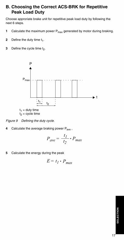
B. Choosing the Correct ACS-BRK for Repetitive Peak Load Duty
Choose approriate brake unit for repetitive peak load duty by following the next 6 steps.
1 Calculate the maximum power Pmax generated by motor during braking.
2 Define the duty time t1.
3 Define the cycle time t2.
Figure 9 Defining the duty cycle.
4 Calculate the average braking power Pave ,
5 Calculate the energy during the peak
t1 t2
t1 = duty timet2 = cycle time
t
P
Pmax
Pave =t1t2
Pmax
E = t1 Pmax

18
6 Choose the brake unit from the figure so that the operating point is within safe operating area. See Figure 10 and Figure 11.
Figure 10 Safe operating area (SOA) for types ACS-BRK-A, -B and -F. Example 1, the resulting point.
Figure 11 Safe operating area (SOA) for types ACS-BRK-C, -D and -E.
Paverage / W
Energy / kJ
0 50 100 150 200 2500
100
200
300
400
ACS-BRK-B
ACS-BRK-A
ACS-BRK-F
SOA for ACS-BRK-B and FSOA for ACS-BRK-A
Energy / kJ
Paverage / kW
0
2
4
6
7
0 500 1000 1500 2000 2500
ACS-BRK-D
ACS-BRK-E
ACS-BRK-C
3000
19
SE
LE
CT
ION
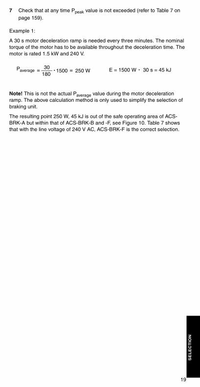
7 Check that at any time Ppeak value is not exceeded (refer to Table 7 on page 159).
Example 1:
A 30 s motor deceleration ramp is needed every three minutes. The nominal torque of the motor has to be available throughout the deceleration time. The motor is rated 1.5 kW and 240 V.
Note! This is not the actual Paverage value during the motor deceleration ramp. The above calculation method is only used to simplify the selection of braking unit.
The resulting point 250 W, 45 kJ is out of the safe operating area of ACS-BRK-A but within that of ACS-BRK-B and -F, see Figure 10. Table 7 shows that with the line voltage of 240 V AC, ACS-BRK-F is the correct selection.
Paverage = 30180
1500. = 250 W E = 1500 W . 30 s = 45 kJ
20
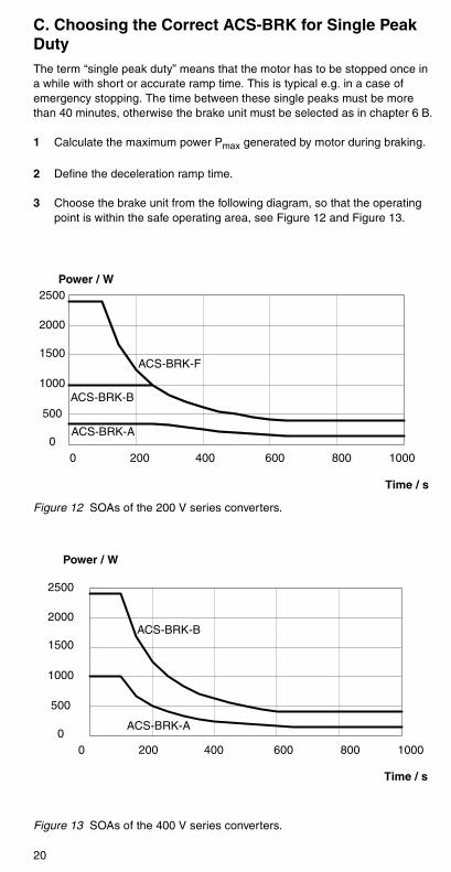
C. Choosing the Correct ACS-BRK for Single Peak DutyThe term “single peak duty” means that the motor has to be stopped once in a while with short or accurate ramp time. This is typical e.g. in a case of emergency stopping. The time between these single peaks must be more than 40 minutes, otherwise the brake unit must be selected as in chapter 6 B.
1 Calculate the maximum power Pmax generated by motor during braking.
2 Define the deceleration ramp time.
3 Choose the brake unit from the following diagram, so that the operating point is within the safe operating area, see Figure 12 and Figure 13.
Figure 12 SOAs of the 200 V series converters.
Figure 13 SOAs of the 400 V series converters.
ACS-BRK-F
ACS-BRK-B
ACS-BRK-A
Time / s
Power / W
0 200 400 600 800 10000
500
1000
1500
2000
2500
ACS-BRK-B
ACS-BRK-A
Power / W
Time / s
0 200 400 600 800 10000
500
1000
1500
2000
2500
21
SE
LE
CT
ION
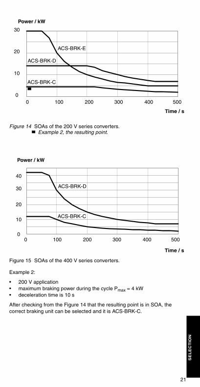
Figure 14 SOAs of the 200 V series converters. Example 2, the resulting point.
Figure 15 SOAs of the 400 V series converters.
Example 2:
• 200 V application• maximum braking power during the cycle Pmax = 4 kW• deceleration time is 10 s
After checking from the Figure 14 that the resulting point is in SOA, the correct braking unit can be selected and it is ACS-BRK-C.
ACS-BRK-E
ACS-BRK-D
ACS-BRK-C
Time / s
Power / kW
0 100 200 300 400 5000
10
20
30
ACS-BRK-D
ACS-BRK-C
Time / s
Power / kW
0 100 200 300 400 5000
10
20
40
30

22


e.
ABB OyDrivesP.O. Box 18400381 HelsinkiFINLANDTelephone +358-10-2211Telefax +358-10-222 2681
3AF
Y 6
1514
309
RE
V C
EN
E
ffect
ive:
16.
09.2
002
© 2
002
AB
B O
yS
ubje
ct to
cha
nge
with
out p
rior
notic