Guidance on the selection, installation, maintenance and use of ...
139
Deep Mined Coal Industry Advisory Committee . . . . . . . . . . . . . . . . . . . . . . . . . Guidance on the selection, installation, maintenance and use of steel wire ropes in vertical mine shafts
Transcript of Guidance on the selection, installation, maintenance and use of ...

Deep Mined Coal
Industry
Advisory
Committee
. . . . . . . . . . . . . . . . . . . . . . . . .
Guidance on the
selection,
installation,
maintenance and
use of steel wire
ropes in vertical
mine shafts

Members of the DMCIAC working group on steel wire ropes for haulage and vertical
shafts at mines
. . . . . . . . . . . . . . . . . . . . . . . . . . . . . . . . . . . . . . . . . . . . . . . . . . . . .
Mr A Kirk A Kirk and Associates (consultant)
Mr J Naylor HM Inspector of Mines
Mr M Holyoak HM Inspector of Mines
Mr PJ McGuiness HM Inspector of Mines
Mr M Williams HM Inspector of Mines
Mr S Denton HM Inspector of Mines
Mr K Acton Mining Association of the United Kingdom
Mr A Bilton Federation of Independent Mines
Mr J Browett UK Coal Mining Ltd
Mr C Clegg Bridon Ropes Ltd
Mr L Hilton Scottish Coal Ltd
Mr SJ Mills British Gypsum Ltd
Mr R Letham National Association of Colliery Overmen, Deputies and Shotfirers
Mr R Young British Association of Colliery Management
Mr A Walker Tower Mine
Mr A Dobbs Union of Democratic Mineworkers
Deep Mined Coal
Industry
Advisory
Committee
. . . . . . . . . . . . . . . . . . . . . . . . .
Guidance on the
selection,
installation,
maintenance and
use of steel wire
ropes in vertical
mine shafts

. . . . . . . . . . . . . . . . . . . . . . . . . . . . . . . . . . . . . . . . . . . . . . . . . . . . . . . . . . .
© Crown copyright 2004
Applications for reproduction should be made in writing
to: Copyright Unit, Her Majesty’s Stationery Office,
St Clements House, 2-16 Colegate, Norwich NR3 1BQ
First published 2004
All rights reserved. No part of this publication may be
reproduced, stored in a retrieval system, or transmitted
in any form or by any means (electronic, mechanical,
photocopying, recording or otherwise) without the prior
written permission of the copyright owner.
This guidance was prepared, in consultation with the
Health and Safety Executive (HSE), by a working group
representative of all sides of the mining industry. The
guidance represents what members of the working group
consider to be good practice. It has been agreed by the
Deep Mined Coal Industry Advisory Committee, the
Mining Association of the United Kingdom and the Health
and Safety Commission.
Following the guidance is not compulsory and you are
free to take other action. But if you do follow the
guidance you will normally be doing enough to comply
with the law. Health and safety inspectors seek to secure
compliance with the law and may refer to this guidance
as illustrating good practice.
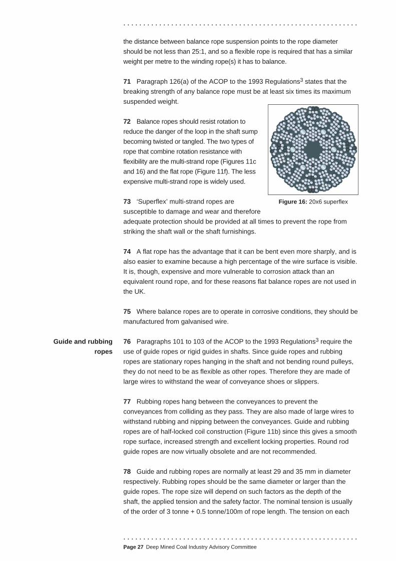
. . . . . . . . . . . . . . . . . . . . . . . . . . . . . . . . . . . . . . . . . . . . . . . . . . . . . . . . . . . Page ii Deep Mined Coal Industry Advisory Committee
. . . . . . . . . . . . . . . . . . . . . . . . . . . . . . . . . . . . . . . . . . . . . . . . . . . . . . . . . . .
CONTENTS
INTRODUCTION..........1
Who should read this document..........1
Rope selection..........1
Winding ropes..........2
Storage of ropes used in shafts..........4
Installation..........4
Capping and recapping..........4
Inspection, examination and testing..........5
Maintenence..........7
Repair and renewal..........8
Keeping records..........9
TECHNICAL ANNEX 1 - TYPES OF SHAFT ROPE INCLUDING SELECTION
PROCESS..........10
Introduction to shaft ropes..........10
Wire shapes..........11
Strand construction..........11
Round strands..........13
Triangular strands..........13
Oval strands..........13
Flat or ribbon strands..........13
Rope construction..........14
Lay..........15
Cores..........16
Rope designation..........17
Rope specifications..........18
Single layer round strand ropes..........18
Single layer triangular strand ropes..........18
Multi-strand ropes..........19
Flat ropes..........19
Full-locked coil ropes..........20
Half-locked coil ropes..........22
Preforming..........22
Surface finishing (galvanising)..........22
Rope selection..........24
Winding ropes..........24
Balance ropes..........26
Guide and rubbing ropes..........27
. . . . . . . . . . . . . . . . . . . . . . . . . . . . . . . . . . . . . . . . . . . . . . . . . . . . . . . . . . . Page iii Deep Mined Coal Industry Advisory Committee

. . . . . . . . . . . . . . . . . . . . . . . . . . . . . . . . . . . . . . . . . . . . . . . . . . . . . . . . . . .
TECHNICAL ANNEX 2 - ROPE STORAGE, HANDLING AND
INSTALLATION..........29
Rope storage..........29
Unreeling and handling ropes..........29
Installation and operation of ropes..........29
Hazard indentification, risk assessment and method statements ..........29
Winding rope installation..........29
Headgear pulley grooves..........30
Polyurethane inserts..........30
Winding drum grooves..........30
Reference samples..........31
Torque and twist in winding ropes..........31
Pre-stretching and pre-stressing by the manufacturer..........32
Correct coiling of stranded ropes on drum winders..........32
Rope tensions in friction-winder ropes..........34
Installation and operation of balance ropes..........36
Installation and attachment of guide and rubbing ropes..........38
TECHNICAL ANNEX 3 - THE SERVING AND CAPPING OF GUIDE
ROPES..........40
Introduction..........40
Hazards from inadequate capping procedures..........40
Rope serving..........41
Serving and clamping..........41
Serving..........41
Size of serving wire..........41
Length of serving..........43
Serving tools..........43
The ordinary or buried wire serving..........44
The soldered or wiped serving..........45
Capping with resin or molten white metal..........46
Cutting the rope and forming the brush..........47
Cutting..........47
Preparing the brush..........47
Forming a resin capping..........52
Health and safety requirements during resin capping..........52
Material..........53
Preparation, cleaning and positioning of the rope and socket - additional
guidance for resin capping..........53
Temperatures..........56
Mixing..........57
Pouring..........58
Curing..........58
Inspection..........59
Marking..........59
. . . . . . . . . . . . . . . . . . . . . . . . . . . . . . . . . . . . . . . . . . . . . . . . . . . . . . . . . . . Page iv Deep Mined Coal Industry Advisory Committee

. . . . . . . . . . . . . . . . . . . . . . . . . . . . . . . . . . . . . . . . . . . . . . . . . . . . . . . . . . .
Re-lubrication..........59
Handling..........59
Disposal of resin residue..........60
Other safety precautions..........60
Reporting..........60
Application of service loading..........60
Resin kit sizes..........60
Capping with white metal..........61
Dismantling the clamps and servings..........63
Possible faults in procedure..........63
Recovery of a socket..........64
Wedge capping..........64
Serving and clamping..........65
Cutting..........65
Fitting the safety block..........65
Fitting the capping..........66
Capping of balance ropes..........68
Resin or white metal cappings..........69
Thimble and clamp terminal fastenings for flat balance ropes..........69
Capping of guide and rubbing ropes..........69
White metal capping..........69
Resin capping..........70
Wedge type suspension glands..........71
Assembling the gland..........71
Dismantling a gland..........72
TECHNICAL ANNEX 4 - MAINTENANCE PROCEDURE, DETERIORATION
AND DISCARD CRITERIA FOR SHAFT ROPES..........74
Maintenance procedures..........74
Introduction..........74
Rope lubrication..........75
Lubrication of ropes during manufacture..........75
Lubrication and cleaning during service..........76
Drum-winder ropes..........76
Friction winder ropes..........78
Pressure lubrication..........79
Balance ropes..........79
Guide ropes..........79
Lubrication after capping..........80
Deterioration in shaft ropes..........80
Wear..........80
External wear..........81
Internal wear..........81
How wear leads to breakage..........82
Wear fractures..........83
Corrosion..........84
. . . . . . . . . . . . . . . . . . . . . . . . . . . . . . . . . . . . . . . . . . . . . . . . . . . . . . . . . . .
.Page v Deep Mined Coal Industry Advisory Committee

. . . . . . . . . . . . . . . . . . . . . . . . . . . . . . . . . . . . . . . . . . . . . . . . . . . . . . . . . . .
External corrosion..........84
Internal corrosion..........85
Corrosion fractures..........85
Fatigue..........85
Secondary bending fatigue..........86
Fatigue fractures..........88
Corrosion-fatigue..........89
Corrosion-fatigue fractures..........89
Surface embrittlement..........89
Plastic-wear embrittlement..........89
Martensitic embrittlement..........90
Surface embrittlement fractures..........91
Accidental damage and distortion..........91
Kinking..........91
Slack rope..........92
Distortion in ropes..........92
Fractures at damage and distortions..........93
Repair of locked coil winding ropes..........93
Non-destructive testing..........94
When to discard a rope..........95
Types of deterioration in shaft ropes..........96
Types of deterioration affecting winding ropes..........96
Wear..........98
Corrosion..........100
Fatigue..........100
Corrosion-fatigue..........101
Distortion..........102
Martensitic embrittlement..........102
Types of deterioration affecting balance ropes..........103
Corrosion..........103
Wear..........103
Damage and distortion..........104
When to discard a balance rope..........105
Types of deterioration affecting guide and rubbing ropes..........105
Wear..........105
Corrosion..........105
When to discard a guide or rubbing rope..........106
APPENDIX 1 - REPORT ON THE CAPPING OF SHAFT ROPES USING
RESIN..........109
APPENDIX 2 - REPORT ON PERIODIC EXAMINATION OF WINDING ROPES
AND BALANCE ROPES..........111
APPENDIX 3 - REPORT OF INTERNAL EXAMINATION OF LENGTH OF
WINDING ROPE CUT OFF DURING RECAPPING..........113
. . . . . . . . . . . . . . . . . . . . . . . . . . . . . . . . . . . . . . . . . . . . . . . . . . . . . . . . . . . Page vi Deep Mined Coal Industry Advisory Committee

. . . . . . . . . . . . . . . . . . . . . . . . . . . . . . . . . . . . . . . . . . . . . . . . . . . . . . . . . . .
APPENDIX 4 - SAMPLE OF A REPORT OF THE THOROUGH
EXAMINATION AND TESTING OF A ROPE SAMPLE..........115
APPENDIX 5 - REPORT OF PERIODIC EXAMINATION OF GUIDE AND
RUBBING ROPES..........119
APPENDIX 6 - PROCEDURE FOR THE NON-DESTRUCTIVE TESTING OF
LOCKED COIL ROPES..........123
APPENDIX 7 - REDUCTION IN EFFECTIVE AREA DUE TO WEAR ON HALF
LOCK GUIDE ROPES..........129
APPENDIX 8 - ROPES ON LIFTS IN MINE SHAFTS..........131
REFERENCES AND FURTHER READING..........132
. . . . . . . . . . . . . . . . . . . . . . . . . . . . . . . . . . . . . . . . . . . . . . . . . . . . . . . . . . .
.Page vii Deep Mined Coal Industry Advisory Committee

. . . . . . . . . . . . . . . . . . . . . . . . . . . . . . . . . . . . . . . . . . . . . . . . . . . . . . . . . . .
Who should read this
document
Rope selection
INTRODUCTION
1 This guidance covers winding ropes, balance ropes, guide ropes and
rubbing ropes.
2 The failure of a steel wire rope while in service is potentially disastrous,
particularly when being used as part of a winding system transporting a large
number of people in a vertical shaft. Even when not transporting people, a rope
failure gives rise to significant risks to people working near the shaft. Any rope
failure could cause damage to winding equipment and the shaft itself putting it
out of action. Apart from giving rise to very hazardous recovery operations, the
loss of one means of egress presents additional risk to everyone below ground.
3 This guidance is aimed primarily at owners, managers, members of the
management structure and any other person who manufactures, selects,
installs, inspects, examines or maintains shaft ropes used in vertical winding
systems. Other non-mining employers who use similar ropes may also find
some of this guidance useful and the HSC guidance on haulage ropes,1 for
example, the parts on capping, storage and handling of steel wire ropes.
4 This guidance deals mainly with the selection, installation and maintenance
of steel wire ropes used in vertical mine shafts. It is split into an introductory
section which gives a broad outline of good practice; and four technical
annexes covering winding, balance and guide ropes as follows:
Technical Annex 1 - Types of shaft rope including selection process;
Technical Annex 2 - Rope storage, handling and installation;
Technical Annex 3 - The serving and capping of shaft ropes;
Technical Annex 4 - Maintenance procedures, deterioration and discard
criteria for shaft ropes.
5 The general advice in this document should also be applied to lift ropes
where appropriate, further specific advice on lifts in mine shafts is included at
Appendix 8.
6 Regulation 13 of the Mines (Shafts and Winding) Regulations 1993 (‘the
1993 Regulations’)2 requires mine owners to specify the type of rope used in any
winding apparatus. Before selecting a rope, owners will need to take advice from
people who have the necessary knowledge, experience or expertise. Rope
manufacturers can provide assistance in matching a rope to a particular duty and
can undertake any calculations that might be necessary. A collaborative
approach can often enable problems to be anticipated and avoided or minimised.
7 Wire ropes used in vertical mine shafts have to be both strong enough to
do the work required and be matched as closely as possible to the conditions in
. . . . . . . . . . . . . . . . . . . . . . . . . . . . . . . . . . . . . . . . . . . . . . . . . . . . . . . . . . .
.Page 1 Deep Mined Coal Industry Advisory Committee

. . . . . . . . . . . . . . . . . . . . . . . . . . . . . . . . . . . . . . . . . . . . . . . . . . . . . . . . . . .
which they will have to operate. There are a number of factors to consider when
selecting a wire rope for a shaft winding system:
■ depth of shaft;
■ type of winding system in use;
■ duty of winding system;
■ shaft environment;
■ frequency of use;
■ the factor of safety of the rope. (Note - paragraphs 126 to 129 of the
Approved Code of Practice (ACOP) to the 1993 Regulations3 contain details
of the minimum factor of safety and maximum specified life of shaft ropes.)
It is then possible to determine:
■ rope size - diameter;
■ rope construction - locked coil or stranded (round strand, triangular strand
or multi-strand); number, size and shape of wires (the fewer the number of
wires, the greater the resistance to wear and corrosion; the greater the
number of wires the more flexible the rope); the tensile strength of the
wires (details of wire tensile strengths are given in Technical Annex 1);
■ type and direction of lay - Lang’s or ordinary lay; right or left-hand lay;
■ surface finish of the wires - ungalvanised (bright) for conditions known to
be dry and non-corrosive or galvanised (zinc coated) for conditions known
to be wet or possibly corrosive;
■ breaking force - to achieve appropriate factor of safety.
Technical Annex 1 contains detailed guidance on rope selection.
8 Paragraph 130 of the ACOP to the 1993 Regulations3 provides further
information for extending the specified life of an in-service rope and for
increasing the specified life of a new rope.
Winding ropes 9 The main items to be considered in choosing a winding rope are:
■ the type of rope - locked coil or stranded (round strand, triangular strand or
multi-strand); for stranded ropes, the shape and construction of the strand
the fewer the number of wires the greater the resistance to wear and
corrosion; or the greater the number of wires the more flexible the rope
direction of lay - right or left-hand; type of lay - Lang’s or ordinary;
. . . . . . . . . . . . . . . . . . . . . . . . . . . . . . . . . . . . . . . . . . . . . . . . . . . . . . . . . . . Page 2 Deep Mined Coal Industry Advisory Committee

. . . . . . . . . . . . . . . . . . . . . . . . . . . . . . . . . . . . . . . . . . . . . . . . . . . . . . . . . . .
■ the shape and tensile strength grades of wires - details of wire tensile
strengths are given in Technical Annex 1;
■ the surface finish of the wires - ungalvanised (bright) for conditions known
to be dry and non-corrosive or galvanised (zinc coated) for conditions
known to be wet or possibly corrosive.
Balance ropes
10 Balance ropes are ropes which are used between the undersides of shaft
conveyances to balance the weight of the winding ropes on each side of the
winding drum or friction-winding sheave.
11 Balance ropes should:
■ be flexible enough to allow the suspended loop to form without undue
stress on the rope;
■ resist rotation to reduce the chance of the suspended loop becoming
twisted or tangled;
■ have a similar weight per metre to the winding rope(s) it has to balance;
■ have a breaking strength of at least six times the maximum suspended
weight of the rope, to meet the requirements of paragraph 126 of the
ACOP to the 1993 Regulations.3
12 Either multi-strand or flat ropes should be selected as balance ropes, as
these are the only two types which are both sufficiently flexible and resist
rotation. The multi-strand rope is used exclusively in the UK.
13 A multi-strand balance rope usually comprises an assembly of two or more
layers of strands laid helically around a centre. The direction of lay of the outer
strands is opposite (ie contra) to that of the underlying strands. Some multi-
strand rope constructions display little or no tendency to rotate or, if guided,
transmit little or no torque. Such ropes are known as low rotation ropes.
Guide and rubbing ropes
14 Guide and rubbing ropes guide and constrain the conveyances (which
include counterweights where used) to prevent collisions between moving
conveyances and between conveyances and the shaft wall and shaft furnishings.
15 Since guide and rubbing ropes are stationary ropes hanging in the shaft
and do not bend around pulleys they do not have to be as flexible as other
ropes. They should be of half-locked coil construction as these have a smooth
rope surface, increased strength, excellent locking properties and, as they are
made of large wires, will withstand the wear of conveyance shoes or slippers.
. . . . . . . . . . . . . . . . . . . . . . . . . . . . . . . . . . . . . . . . . . . . . . . . . . . . . . . . . . .
.Page 3 Deep Mined Coal Industry Advisory Committee

. . . . . . . . . . . . . . . . . . . . . . . . . . . . . . . . . . . . . . . . . . . . . . . . . . . . . . . . . . .
16 Guide and rubbing ropes are normally at least 29 mm and 35 mm in
diameter respectively, and when new should have a factor of safety of at
least five, to meet the requirements of paragraph 102 of the ACOP to the
1993 Regulations.3 A new European Standard prEN 12385 - 7 Steel wire
ropes - safety - Part 7: Locked coil ropes for mine hoists is currently being
prepared. It includes requirements for guide and rubbing ropes as well as
hoist ropes.
Storage of ropes used 17 If a rope is stored prior to installation, precautions should be taken to
in shafts prevent external or internal corrosion. Ropes should be stored in a dry,
cool, well-ventilated building out of direct sunlight and where the
temperature remains substantially steady and does not rise much above
16oC. Further guidance on rope storage and handling can be found in
Technical Annex 2.
Installation 18 Prior to installing any rope in a winding system, the potential hazards of the
installation process should be identified and an assessment of risks carried out.
Write down the significant findings of any risk assessment and take account of
them when determining the installation procedure. After determining the
installation procedure method statements can be drawn up detailing:
■ what work is to be done;
■ how it is to be done;
■ what steps are to be taken to avoid, control or mitigate risks.
20 Whatever the method of work care should be taken to prevent rope
damage during installation.
20 More detail relating to the installation of ropes in winding systems may be
found in Technical Annex 2.
Capping and recapping 21 It is essential to use cappings to properly terminate the wire ropes used in
winding systems, and provision should be made for them to be recapped at
regular intervals after they have been taken into use. Procedures for capping
wire ropes properly are given in Technical Annex 3.
Types of capping
22 Resin, white metal or wedge-type cappings are the main types available.
HSE strongly recommends resin or white metal capping on ropes used in
winding systems.
23 Of the two, resin capping is slightly stronger than white metal capping,
less hazardous to install and quality control over the installation process is
easier. For these reasons, resin cappings are now used almost exclusively in
UK mines.
. . . . . . . . . . . . . . . . . . . . . . . . . . . . . . . . . . . . . . . . . . . . . . . . . . . . . . . . . . . Page 4 Deep Mined Coal Industry Advisory Committee

. . . . . . . . . . . . . . . . . . . . . . . . . . . . . . . . . . . . . . . . . . . . . . . . . . . . . . . . . . .
Intervals between capping
24 Because of their safety critical duties, winding rope cappings have to be
changed periodically. Paragraph 194 of the ACOP to the 1993 Regulations3
sets out the appropriate intervals for the capping of winding ropes for different
types of winding systems.
25 Balance rope cappings can remain in service for the statutory life of the
rope, which varies dependent upon whether the rope is fitted to a drum winder
or a friction winder. The maximum interval that a rope is allowed to remain in
service is specified in paragraph 129 of the ACOP to the 1993 Regulations.3
However, if the service life of any balance rope is extended beyond the life
specified in the ACOP then recapping should be considered.
26 Guide ropes and rubbing ropes should be lifted and recapped as stated in
paragraph 203 of the ACOP to the 1993 Regulations.3
Appointment of competent people to carry out capping
27 The capping and recapping of any wire rope used in a winding system
should only be carried out by, or under the supervision of, a competent person
appointed by the manager.
Inspection, 28 Regulation 11 of the Management and Administration of Safety and Health at
examination and Mines Regulations 1993 (MASHAM)4 requires that wire ropes used in winding
testing systems be included in the manager’s scheme for the systematic inspection,
examination and testing of plant and equipment. Regulation 17 of the 1993
Regulations2 and the corresponding ACOP3 paragraphs 185 to 203 contain further
detailed information. The purpose of inspecting and examining wire ropes is to:
■ check that a rope remains safe to use;
■ check the general condition of the rope, and in particular to identify the
nature and severity of any damage, deformation or deterioration to the
rope so it can be properly repaired or replaced; and
■ identify and prevent, where possible, the causes of such damage etc.
29 Details on the types of damage, deformation and deterioration that might
be found during inspection or examination are given in Technical Annex 4.
30 Criteria to help determine when to discard worn-out, damaged or defective
ropes are also detailed in Technical Annex 4.
People carrying out rope inspections
31 Managers should only appoint trained and competent people to inspect,
examine, test and maintain ropes used in winding systems as required by
regulation 17 of the 1993 Regulations.2
. . . . . . . . . . . . . . . . . . . . . . . . . . . . . . . . . . . . . . . . . . . . . . . . . . . . . . . . . . .
.Page 5 Deep Mined Coal Industry Advisory Committee

. . . . . . . . . . . . . . . . . . . . . . . . . . . . . . . . . . . . . . . . . . . . . . . . . . . . . . . . . . .
Routine external inspection
32 All wire ropes used in winding systems which carry people should be
inspected daily. Reference should also be made to paragraph 188 of the ACOP
to the 1993 Regulations.3
Periodic thorough examination
33 Winding and balance ropes used in winding systems should be subjected
to a periodic thorough examination at least every 30 days. The examination
procedure should be appropriate to the specimen report form shown at
Appendix 2.
34 Paragraph 202 of the ACOP3 specifies that guide and rubbing ropes
should be examined at regular intervals. For heavily used winding systems the
examination should be made at least every 90 days. For winding systems with
lighter duties in non-corrosive conditions the interval may be extended as
appropriate but should not exceed six months. The factors considered during
any examination and assessment procedure are shown in the specimen report
forms in Appendix 5.
Thorough examination of rope removed during recapping
35 Paragraph 195 of the ACOP to regulation 17 of the 1993 Regulations3
gives details of the two thorough examinations of the length of rope removed
during the recapping of a winding rope. The specimen report forms contained in
Appendices 3 and 4 detail the factors considered during these thorough
examinations.
Non-destructive testing of wire ropes
36 Non-destructive testing (NDT) can help locate defects in ropes. NDT is
particularly useful for wire ropes used in shafts, where visual internal
examination is not possible. NDT should be carried out when a rope is first
installed, and then periodically throughout its statutory life. The provision of
such condition monitored data is an essential requirement of any application to
HSE to extend the life of a rope beyond its statutory limit. Reference should be
made to paragraph 130 of the ACOP to the 1993 Regulations.3
37 Using NDT on balance ropes and guide ropes will give an earlier indication
of deterioration than visual inspection. The ultrasonic testing of guide ropes in
the area of the suspension gland has proved to be a reliable means of detecting
deterioration in that area of the rope that is most likely to first suffer from fatigue.
38 The NDT of ropes requires specialist skills and equipment and should only
be carried out by competent people using proven equipment in accordance with
recognised codes of practice. More details on NDT can be found in Technical
Annex 4.
. . . . . . . . . . . . . . . . . . . . . . . . . . . . . . . . . . . . . . . . . . . . . . . . . . . . . . . . . . . Page 6 Deep Mined Coal Industry Advisory Committee
. . . . . . . . . . . . . . . . . . . . . . . . . . . . . . . . . . . . . . . . . . . . . . . . . . . . . . . . . . .
Maintenance Rope maintenance
39 The main elements of rope maintenance are:
■ lubrication;
■ other preventative maintenance;
■ repair or renewal (including recapping).
40 The degree, nature and extent of maintenance will depend on a number of
factors including:
■ statutory requirements;
■ the duty required of the rope;
■ condition of the rope;
■ type of rope;
■ manufacturer’s recommendations;
■ the shaft environment.
41 Rope maintenance or repair should only be carried out by people
competent to do so.
42 Engineers need to ensure that they assess the risks associated with
periodic maintenance work and for other repetitive jobs and draw up method
statements. There should be no need to draw up a new method statement each
time such work is carried out unless circumstances change, in which case the
risks will need to be reassessed. A review of the method statement following
completion of the work is recommended. The statement should be modified to
incorporate any improvements to working practices identified through
experience of performing the work.
Lubrication
43 The main benefits of effective lubrication are:
(a) to allow free movement between strands or layers of wires which helps to
reduce internal wear; and
(b) to prevent or reduce the ingress of mine water or other potentially corrosive
or abrasive materials,
and, therefore, to potentially increase rope life.
. . . . . . . . . . . . . . . . . . . . . . . . . . . . . . . . . . . . . . . . . . . . . . . . . . . . . . . . . . .
.Page 7 Deep Mined Coal Industry Advisory Committee

. . . . . . . . . . . . . . . . . . . . . . . . . . . . . . . . . . . . . . . . . . . . . . . . . . . . . . . . . . .
44 Technical Annex 4 details the various types of lubricant available, the
methods of application and the potential benefits of lubrication.
Other preventative maintenance
45 The purpose of other preventative maintenance is to avoid problems with
shaft ropes during use of the winding system. Engineers should ensure that the
manager’s planned preventative maintenance scheme includes an appropriate
regime of systematic and periodic maintenance. In particular, it should address:
■ shaft ropes;
■ winding engines; and
■ other ancillary equipment and fittings.
46 Appendices 2 and 5 contain two sample report forms that detail the items
that need to be checked, maintained and subsequently reported on with
respect to shaft ropes.
Repair and renewal 47 Defects found during inspection, examination, testing or in use, will need to
be dealt with promptly.
48 If the nature, extent and severity of a defect is sufficient to prejudice the
continued safe running of the winding system then it should be stopped and
prevented from running until a repair is completed or the rope has been replaced.
49 For minor defects the person making the inspection or examination will
have to judge whether or not there is a need to take immediate action. Normal
wear or corrosion is unlikely to warrant immediate action unless the rope is
approaching its discard limits.
50 A single broken wire, which does not give rise to immediate concern,
should be repaired promptly and subsequently monitored regularly to check for
any further deterioration.
51 In addition to the normal rope inspections carried out at the mine, the
person examining the shaft should determine whether or not there are any
matters which might adversely affect the condition of the ropes. Particular
situations to look for include:
■ rope fouling or rubbing on obstructions;
■ areas where localised deterioration may take place ie fan drifts, rope entry holes through headgear casings, wet areas;
■ presence of corrosive or abrasive substances; and
■ any other defects that need correction.
. . . . . . . . . . . . . . . . . . . . . . . . . . . . . . . . . . . . . . . . . . . . . . . . . . . . . . . . . . . Page 8 Deep Mined Coal Industry Advisory Committee

Keeping records
. . . . . . . . . . . . . . . . . . . . . . . . . . . . . . . . . . . . . . . . . . . . . . . . . . . . . . . . . . .
52 As required by paragraph 187 of the ACOP to the 1993 Regulations,3
where problems are identified, they should be recorded and reported so that
appropriate action can be taken.
53 It is important to keep proper records of shaft rope inspections,
examinations, testing, maintenance and repairs. Appendices 1, 2, 3, 4, 5 and 7
are examples of sample report forms and can be freely copied. The forms
outline the areas which should be looked at during inspection, examination or
testing.
54 Conventional reporting procedures by the use of appropriate record books
or electronic data storage can be used for keeping records provided that the
same basic information shown on the sample report forms is included.
55 Whatever form of record is used, the important criteria is that any person
who might need the recorded information has ready access to it.
. . . . . . . . . . . . . . . . . . . . . . . . . . . . . . . . . . . . . . . . . . . . . . . . . . . . . . . . . . .
.Page 9 Deep Mined Coal Industry Advisory Committee
1
. . . . . . . . . . . . . . . . . . . . . . . . . . . . . . . . . . . . . . . . . . . . . . . . . . . . . . . . . . .
TECHNICAL ANNEX 1 - TYPES OF SHAFT ROPE
INCLUDING SELECTION PROCESS
INTRODUCTION TO SHAFT ROPES
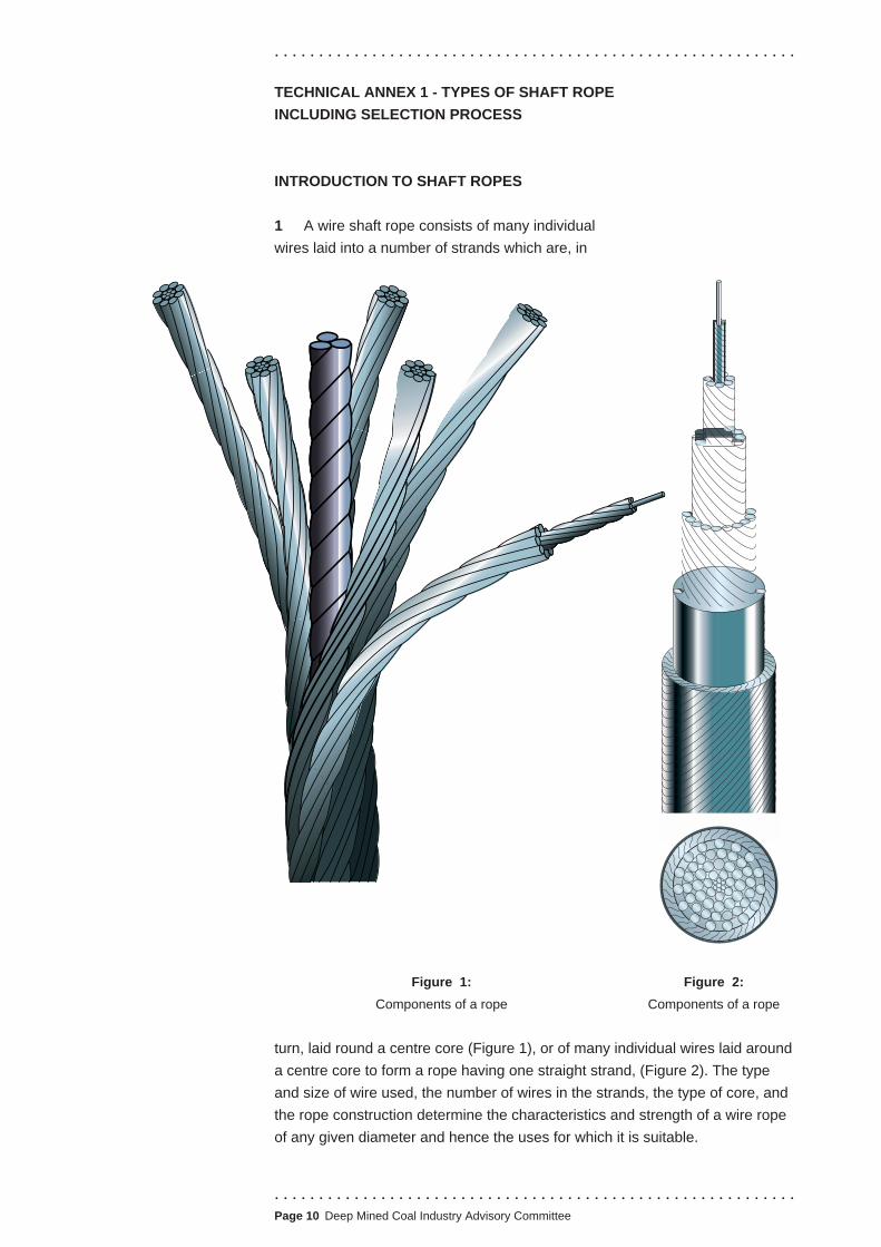
A wire shaft rope consists of many individual
wires laid into a number of strands which are, in
Figure 1: Figure 2:
Components of a rope Components of a rope
turn, laid round a centre core (Figure 1), or of many individual wires laid around
a centre core to form a rope having one straight strand, (Figure 2). The type
and size of wire used, the number of wires in the strands, the type of core, and
the rope construction determine the characteristics and strength of a wire rope
of any given diameter and hence the uses for which it is suitable.
. . . . . . . . . . . . . . . . . . . . . . . . . . . . . . . . . . . . . . . . . . . . . . . . . . . . . . . . . . . Page 10 Deep Mined Coal Industry Advisory Committee

. . . . . . . . . . . . . . . . . . . . . . . . . . . . . . . . . . . . . . . . . . . . . . . . . . . . . . . . . . .
2 Wires for shaft ropes generally have a tensile strength more than four times
that of mild steel. The increased strength is obtained during manufacture, mainly
by drawing the wire several times through small tapered holes in metal blocks or
dies, the holes being always slightly smaller than the wire to be drawn through
them. This treatment steadily decreases the diameter of the wire and increases
its length, elongating the grains of which the steel is composed into longer, fibre-
like structures increasing the tensile strength of the steel and hence the wire.
3 Tensile strength is measured in Newtons per square millimetre (N/mm2).
Hanging a 1 kg weight on a wire would create just under 10 Newtons (10 N) of
tension in that wire. If the wire had a cross-sectional area of 1 mm2 then the
tensile force in that wire would be just under 10 N/mm2.
4 However, wires may fail by the repeated application of relatively small
loads, below those that would be required to induce tensile failure. This
characteristic is called ‘fatigue failure’.
WIRE SHAPES
5 Wire shapes used in the manufacture of shaft ropes are as follows:
■ round - ie circular in cross-section (Figure 3);
■ half-lock - ie rail-shaped, with the sides curved to take a round wire on
each side (Figure 4);
■ triangular - ie
triangular in cross-
section, as used for
the centre wire of
some triangular
strands (Figure 5);
■ full-lock - ie Z-shaped
or shaped like an
inclined bullhead rail
which will fit snugly
against, or lock into,
another wire of the Figure 5: Triangular Figure 6: Full-lock
same shape (Figure 6).
Figure 3: Round Figure 4: Half-lock
STRAND CONSTRUCTION
6 A strand is formed by laying up or spinning one or more layers of wires around
a strand centre (Figure 7). The strand centre is either a single wire or a built-up-
centre of a group of wires. The types and shapes of strands are as follows:
. . . . . . . . . . . . . . . . . . . . . . . . . . . . . . . . . . . . . . . . . . . . . . . . . . . . . . . . . . .
.Page 11 Deep Mined Coal Industry Advisory Committee

. . . . . . . . . . . . . . . . . . . . . . . . . . . . . . . . . . . . . . . . . . . . . . . . . . . . . . . . . . .
■ round (Figures 7a and 7b);
■ triangular (Figures 7c and 7d);
Figure 7a: 6/1 round Figure 7b: 9/9/1 round Figure 7c: 7/∆ triangular
Figure 7d: 9/12/BUC triangular Figure 7e: 9/1 oval Figure 7f: 6/nil flat/ribbon
■ oval (Figure 7e);
■ flat or ribbon, (Figure 7f).
7 Apart from the flat (ribbon) strand, which has no centre, all other types have
a centre to support the outer wires. Figure 8 show the types in general use
those shown in Figures 8b, 8c and 8d are known as built-up-centres (BUC).
Figure 8a: Triangular Figure 8b: Round Figure 8c: 3X2+3F Figure 8d: K6/1 triangular
8 A simple method of describing the construction of a strand is to quote its
type (shape) and the number of wires in each layer, starting from the outside.
In Figure 7a the strand is ‘round 6/1’; in Figure 7d it is ‘triangular 9/12/BUC’; in
Figure 7f it is ‘flat 6/nil’. Paragraphs 26 and 27 of this Technical Annex provide
further advice on the subject of rope designations.
. . . . . . . . . . . . . . . . . . . . . . . . . . . . . . . . . . . . . . . . . . . . . . . . . . . . . . . . . . . Page 12 Deep Mined Coal Industry Advisory Committee
Round strands
. . . . . . . . . . . . . . . . . . . . . . . . . . . . . . . . . . . . . . . . . . . . . . . . . . . . . . . . . . .
9 Round strands may be:
■ single lay - consisting only of one layer of wires around a centre wire
(Figure 7a);
■ equal (parallel) lay - consisting of at least two layers of wires, all of which
are laid in one operation (in the same direction) around a centre wire
(Figure 7b). There are a number of constructions which fall under this
category, namely Seale, Warrington, Filler, Warrington Seale, etc;
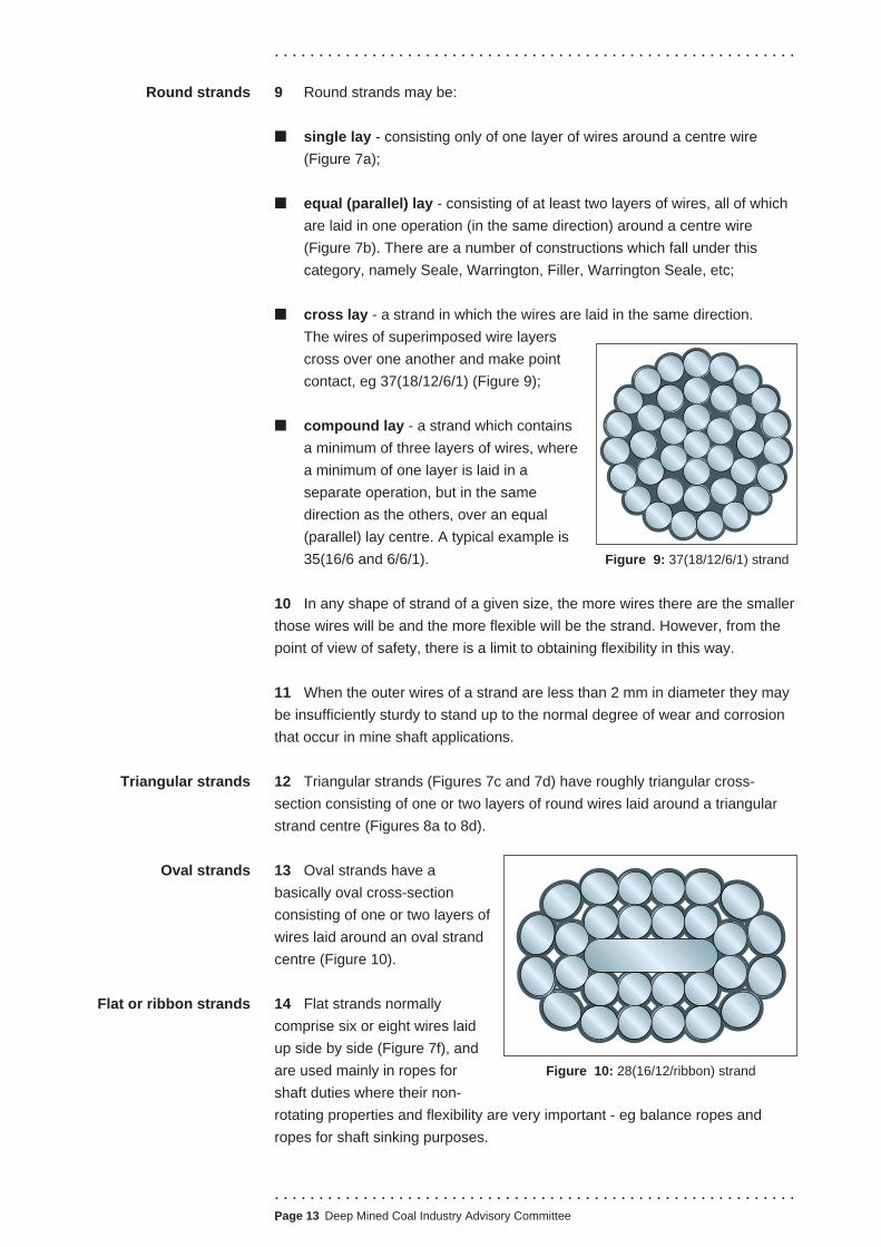
■ cross lay - a strand in which the wires are laid in the same direction.
The wires of superimposed wire layers
cross over one another and make point
contact, eg 37(18/12/6/1) (Figure 9);
■ compound lay - a strand which contains
a minimum of three layers of wires, where
a minimum of one layer is laid in a
separate operation, but in the same
direction as the others, over an equal
(parallel) lay centre. A typical example is
35(16/6 and 6/6/1). Figure 9: 37(18/12/6/1) strand
10 In any shape of strand of a given size, the more wires there are the smaller
those wires will be and the more flexible will be the strand. However, from the
point of view of safety, there is a limit to obtaining flexibility in this way.
11 When the outer wires of a strand are less than 2 mm in diameter they may
be insufficiently sturdy to stand up to the normal degree of wear and corrosion
that occur in mine shaft applications.
12 Triangular strands (Figures 7c and 7d) have roughly triangular cross-
section consisting of one or two layers of round wires laid around a triangular
strand centre (Figures 8a to 8d).
Triangular strands
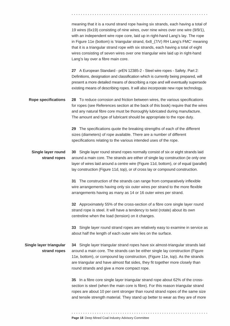
Oval strands 13 Oval strands have a
basically oval cross-section
consisting of one or two layers of
wires laid around an oval strand
centre (Figure 10).
Flat or ribbon strands 14 Flat strands normally
comprise six or eight wires laid
up side by side (Figure 7f), and
are used mainly in ropes for Figure 10: 28(16/12/ribbon) strand
shaft duties where their non-
rotating properties and flexibility are very important - eg balance ropes and
ropes for shaft sinking purposes.
. . . . . . . . . . . . . . . . . . . . . . . . . . . . . . . . . . . . . . . . . . . . . . . . . . . . . . . . . . .
.Page 13 Deep Mined Coal Industry Advisory Committee

. . . . . . . . . . . . . . . . . . . . . . . . . . . . . . . . . . . . . . . . . . . . . . . . . . . . . . . . . . .
ROPE CONSTRUCTION
15 The main types of ropes used in shafts are:
■ full locked coil (Figure 11a);
■ half locked coil (Figure 11b);
■ multi-strand (Figure 11c);
■ round strand (Figure 11d);
■ triangular strand (Figure 11e);
■ flat (Figure 11f).
16 The full and half locked coil types are spiral, single-strand ropes containing
shaped and round wires.
Figure 11a: Full locked coil rope Figure 11b: Half locked coil rope Figure 11c: Multi-strand rope
. . . . . . . . . . . . . . . . . . . . . . . . . Page 14 Deep Mined Coal Industry Advisory Committee. . . . . . . . . . . . . . . . . . . . . . . . . . . . . . . . . .

. . . . . . . . . . . . . . . . . . . . . . . . . . . . . . . . . . . . . . . . . . . . . . . . . . . . . . . . . . .
. . . . . . . . . . . . . . . . . . . . . . . . . . . . . . . . . . . . . . . . . . . . . . . . . . . . . . . . . . .
.Page 15 Deep Mined Coal Industry Advisory Committee
17 The multi-strand, round strand and triangular strand types have strands
that twist around a core like screw threads. If they twist in the same direction as
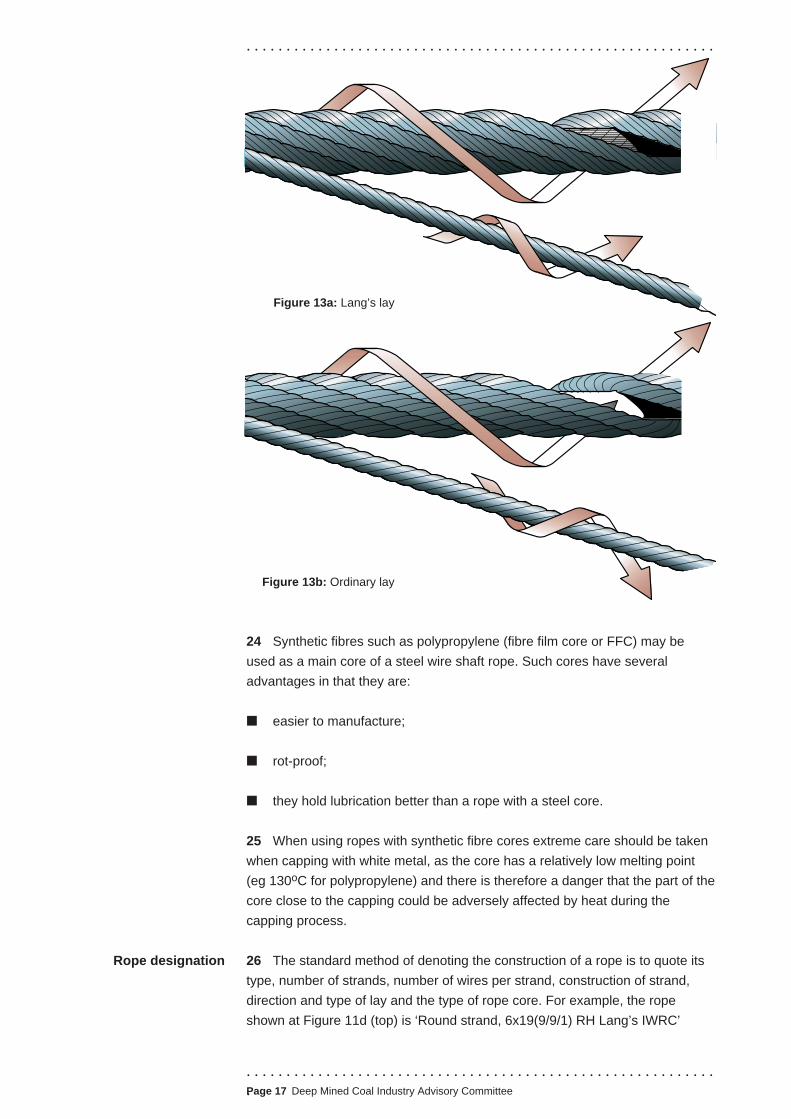
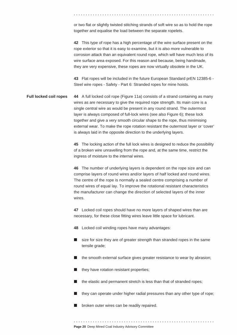
a right-hand thread then the rope is in right-hand lay (Figures 12a and 12c); if
they twist in the opposite direction it is in left-hand lay (Figures 12b and 12d).
The individual wires also twist around the strands. If they twist in the same
direction as the strands, then the rope is in Lang’s lay (Figure 13a), and if they
twist in the opposite direction to that of the strands, then the rope is in ordinary
lay (Figure 13b).
18 If the direction is not specified, the manufacturer will always supply right-
hand lay as standard. The best lay for normal purposes is Lang’s right-hand
lay; engineers should only specify other
lays when there is a special reason for
doing so.
19 The length of lay (or pitch) of a
stranded rope is the distance, measured
along the rope, between the crown
(highest point) of one strand and the next
Lay
Figure 11d: Round strand rope Figure 11e: Triangular strand rope Figure 11f: Flat rope

Figure 12a:
Lang’s right hand
Figure 12b:
Lang’s left hand
Figure 12c:
Ordinary right hand
Figure 12d:
Ordinary left hand
One rope lay
One rope lay
One rope lay
One rope lay
crown of that strand along the rope. In Figure 12 one strand has been shaded and
the distance between the two crowns, representing the length of lay, is marked.
Cores 20 The core of a stranded rope is designed to support the strands and is
usually:
■ a fibre rope (fibre core or FC);
■ a wire strand (wire strand core or WSC); or
■ a small wire rope (independent wire rope core or IWRC).
21 A rope with a fibre core, which may be of natural or synthetic fibres, is
flexible and suitable for all conditions except those in which the rope is
subjected to severe crushing (working under high load and on very small
pulleys and drums, coiling on top of itself in numerous layers on a drum, etc.).
22 A rope with a wire strand core is more resistant to crushing but less flexible.
23 A rope with an independent wire rope core (Figure 11d - top) is resistant to
crushing but is more flexible than a wire strand core rope. The reference section
at the back of this book contains more information on relevant standards.
. . . . . . . . . . . . . . . . . . . . . . . . . . . . . . . . . . . . . . . . . . . . . . . . . . . . . . . . . . . Page 16 Deep Mined Coal Industry Advisory Committee
Rope designation
. . . . . . . . . . . . . . . . . . . . . . . . . . . . . . . . . . . . . . . . . . . . . . . . . . . . . . . . . . .
Figure 13a: Lang’s lay
Figure 13b: Ordinary lay
24 Synthetic fibres such as polypropylene (fibre film core or FFC) may be
used as a main core of a steel wire shaft rope. Such cores have several
advantages in that they are:
■ easier to manufacture;
■ rot-proof;
■ they hold lubrication better than a rope with a steel core.
25 When using ropes with synthetic fibre cores extreme care should be taken
when capping with white metal, as the core has a relatively low melting point
(eg 130oC for polypropylene) and there is therefore a danger that the part of the
core close to the capping could be adversely affected by heat during the
capping process.
26 The standard method of denoting the construction of a rope is to quote its
type, number of strands, number of wires per strand, construction of strand,
direction and type of lay and the type of rope core. For example, the rope
shown at Figure 11d (top) is ‘Round strand, 6x19(9/9/1) RH Lang’s IWRC’
. . . . . . . . . . . . . . . . . . . . . . . . . . . . . . . . . . . . . . . . . . . . . . . . . . . . . . . . . . .
.Page 17 Deep Mined Coal Industry Advisory Committee
Rope specifications
Single layer round
strand ropes
Single layer triangular
strand ropes
. . . . . . . . . . . . . . . . . . . . . . . . . . . . . . . . . . . . . . . . . . . . . . . . . . . . . . . . . . .
meaning that it is a round strand rope having six strands, each having a total of
19 wires (6x19) consisting of nine wires, over nine wires over one wire (9/9/1),
with an independent wire rope core, laid up in right-hand Lang’s lay. The rope
in Figure 11e (bottom) is ‘triangular strand, 6x8_(7/V) RH Lang’s FMC’ meaning
that it is a triangular strand rope with six strands, each having a total of eight
wires consisting of seven wires over one triangular wire laid up in right-hand
Lang’s lay over a fibre main core.
27 A European Standard - prEN 12385-2 - Steel wire ropes - Safety. Part 2:
Definitions, designation and classification which is currently being prepared, will
present a more detailed means of describing a rope and will eventually supersede
existing means of describing ropes. It will also incorporate new rope technology.
28 To reduce corrosion and friction between wires, the various specifications
for ropes (see References section at the back of this book) require that the wires
and any natural fibre core must be thoroughly lubricated during manufacture.
The amount and type of lubricant should be appropriate to the rope duty.
29 The specifications quote the breaking strengths of each of the different
sizes (diameters) of rope available. There are a number of different
specifications relating to the various intended uses of the rope.
30 Single layer round strand ropes normally consist of six or eight strands laid
around a main core. The strands are either of single lay construction (ie only one
layer of wires laid around a centre wire (Figure 11d, bottom), or of equal (parallel)
lay construction (Figure 11d, top), or of cross lay or compound construction.
31 The construction of the strands can range from comparatively inflexible
wire arrangements having only six outer wires per strand to the more flexible
arrangements having as many as 14 or 16 outer wires per strand.
32 Approximately 55% of the cross-section of a fibre core single layer round
strand rope is steel. It will have a tendency to twist (rotate) about its own
centreline when the load (tension) on it changes.
33 Single layer round strand ropes are relatively easy to examine in service as
about half the length of each outer wire lies on the surface.
34 Single layer triangular strand ropes have six almost-triangular strands laid
around a main core. The strands can be either single lay construction (Figure
11e, bottom), or compound lay construction, (Figure 11e, top). As the strands
are triangular and have almost flat sides, they fit together more closely than
round strands and give a more compact rope.
35 In a fibre core single layer triangular strand rope about 62% of the cross-
section is steel (when the main core is fibre). For this reason triangular strand
ropes are about 10 per cent stronger than round strand ropes of the same size
and tensile strength material. They stand up better to wear as they are of more
. . . . . . . . . . . . . . . . . . . . . . . . . . . . . . . . . . . . . . . . . . . . . . . . . . . . . . . . . . . Page 18 Deep Mined Coal Industry Advisory Committee

. . . . . . . . . . . . . . . . . . . . . . . . . . . . . . . . . . . . . . . . . . . . . . . . . . . . . . . . . . .
. . . . . . . . . . . . . . . . . . . . . . . . . . . . . . . . . . . . . . . . . . . . . . . . . . . . . . . . . . .
.Page 19 Deep Mined Coal Industry Advisory Committee
smoothly circular shape, and they resist crushing better as the strands have a
greater bearing area.
36 Single layer triangular strand ropes are slightly more difficult to examine in
service as a smaller proportion of total length of wire in the rope can be
examined at the surface of the rope.
37 Multi-strand ropes generally consist of an assembly of two or more layers of
strands laid helically around a central core, the direction of lay of the outer strands
being opposite (ie contra lay) to that of the underlying layer of strands. Depending
upon the number of strands the amount of resistance to rotation will vary.
38 This type of rope is not easy to examine visually as only about half the length
of the outer wires of one layer of strands can be seen and there may be several
layers of inner strands whose wires cannot be seen at all unless the rope is
carefully opened up (Figures 14a and 14b). It is a fairly flexible type of rope, with
the degree of flexibility depending on the number and shape of the strands.
39 Rotation resistant and low rotation multi-strand ropes are suitable for
conditions where rope twist must be minimised but where flexibility is required
(as for balance ropes).
40 There is no British Standard or NCB Specification for multi-strand ropes for
mine shaft purposes, but BS EN 12385-1:20025 and BS 302-6:19876 cover
these ropes for general engineering purposes. Multi-strand ropes for mine
hoists will be included in the future European Standard prEN 12385-6 -Steel
wire ropes - Safety - Part 6: Stranded ropes for mine hoists.
41 A flat rope (Figure 11f) is made up of several ropes called ‘strands’ or
‘ropelets’ laid side by side. The ropelets are normally stitched together with one
Multi-strand ropes
Flat ropes
Figures 14a and b: Internal examination of a stranded rope
. . . . . . . . . . . . . . . . . . . . . . . . . . . . . . . . . . . . . . . . . . . . . . . . . . . . . . . . . . .
or two flat or slightly twisted stitching strands of soft wire so as to hold the rope
together and equalise the load between the separate ropelets.
42 This type of rope has a high percentage of the wire surface present on the
rope exterior so that it is easy to examine, but it is also more vulnerable to
corrosion attack than an equivalent round rope, which will have much less of its
wire surface area exposed. For this reason and because, being handmade,
they are very expensive, these ropes are now virtually obsolete in the UK.
43 Flat ropes will be included in the future European Standard prEN 12385-6
Steel wire ropes - Safety - Part 6: Stranded ropes for mine hoists.
Full locked coil ropes 44 A full locked coil rope (Figure 11a) consists of a strand containing as many
wires as are necessary to give the required rope strength. Its main core is a
single central wire as would be present in any round strand. The outermost
layer is always composed of full-lock wires (see also Figure 6); these lock
together and give a very smooth circular shape to the rope, thus minimising
external wear. To make the rope rotation resistant the outermost layer or ‘cover’
is always laid in the opposite direction to the underlying layers.
45 The locking action of the full lock wires is designed to reduce the possibility
of a broken wire unravelling from the rope and, at the same time, restrict the
ingress of moisture to the internal wires.
46 The number of underlying layers is dependent on the rope size and can
comprise layers of round wires and/or layers of half locked and round wires.
The centre of the rope is normally a sealed centre comprising a number of
round wires of equal lay. To improve the rotational resistant characteristics
the manufacturer can change the direction of selected layers of the inner
wires.
47 Locked coil ropes should have no more layers of shaped wires than are
necessary, for these close fitting wires leave little space for lubricant.
48 Locked coil winding ropes have many advantages:
■ size for size they are of greater strength than stranded ropes in the same
tensile grade;
■ the smooth external surface gives greater resistance to wear by abrasion;
■ they have rotation resistant properties;
■ the elastic and permanent stretch is less than that of stranded ropes;
■ they can operate under higher radial pressures than any other type of rope;
■ broken outer wires can be readily repaired.
. . . . . . . . . . . . . . . . . . . . . . . . . . . . . . . . . . . . . . . . . . . . . . . . . . . . . . . . . . . Page 20 Deep Mined Coal Industry Advisory Committee

. . . . . . . . . . . . . . . . . . . . . . . . . . . . . . . . . . . . . . . . . . . . . . . . . . . . . . . . . . .
49 Locked coil ropes are less flexible than other types of rope. To ensure long
service the rope should not be bent sharply and should work on drums and
pulleys whose diameters are not less than those shown in Table 1.
50 For these reasons this type of rope is particularly suitable as a winding
rope in cases where large loads have to be raised and where rope twist cannot
be tolerated.
Rope type
Locked coil ropes
Rope size
less than 26 mm
Drum/Pulley ratio
80
26-44 mm 100
more than 44 mm 120
Stranded ropes All sizes 80
Table 1: Minimum drum and pulley/rope diameter ratios for winding ropes
51 Locked coil ropes have some disadvantages:
(a) Only one layer of wires, representing between 18% and 40% of the total
length of all wire in the rope (depending upon the rope size and
construction) is visible, and it is therefore impossible to visually examine
the wires of the underlying layers.
(b) During service, locked coil ropes, generally over 45 mm diameter, may
develop a wavy or spiral form instead of remaining straight (Figure 15).
The reason for this is that the larger ropes are built up of more layers of
wires, and are more complex than smaller ropes. As such they are more
readily affected by any deficiency in manufacturing techniques or operating
conditions. See further advice on this subject in Technical Annex 4 under
‘Distortion in ropes’. Modern friction winding installations, designed to
raise heavy loads, are of the multi-rope type employing several small
locked coil ropes in parallel rather than one large rope. This is better for
service and smaller ropes can work on smaller driving sheaves.
(c) There is no British Standard for locked coil ropes, but NCB Specification
No 186: 19707 applies. It should be noted however, that full locked coil
hoist ropes will be included in the future European Standard prEN 12385 -7
Steel wire ropes - Safety. Part 7: Locked coil ropes for mine hoists.
Figure 15:
Wavy or spiral form
. . . . . . . . . . . . . . . . . . . . . . . . . . . . . . . . . . . . . . . . . . . . . . . . . . . . . . . . . . .
.Page 21 Deep Mined Coal Industry Advisory Committee
Half-locked coil ropes
. . . . . . . . . . . . . . . . . . . . . . . . . . . . . . . . . . . . . . . . . . . . . . . . . . . . . . . . . . .
52 Half-locked coil ropes (for guide and rubbing ropes) also consist of one
straight strand (Figure 11b) and contain very large section wires to give the best
possible wear characteristics. Used as guide ropes they offer a smooth wearing
surface to the conveyance shoe or rubbing plate. The locking action of the outer
wires is designed to ensure that any broken wires which develop are held in
position in the rope so as not to interfere with the free running of a conveyance.
53 There is no British Standard for half-locked coil ropes but NCB Specification
No 388/19708 applies. It should be noted however that half-locked coil guide
and rubbing ropes using wires of tensile strength grade 780 to 1270 N/mm2. will
be included in the future European Standard prEN 12385-7 Steel wire ropes
Safety: Part 7: Locked coil ropes for mining hoists.
54 Table 2 lists the advantages and disadvantages of most of the rope types.
PREFORMING
55 Most types of stranded ropes are preformed to some degree during
manufacture to give the strands and wires the form they will take up in the
completed rope. This process produces a rope which does not tend to unravel
or to form itself into loops or kinks when it is slack or free of load. It will however
still twist when loaded.
SURFACE FINISHING (GALVANISING)
56 Many steel wire ropes are coated with zinc in a process known as
‘galvanising’. A zinc coating protects the steel, partly by acting as a physical barrier
between the steel and any corrosive substance, and partly because the coating is
attacked rather than the steel. Galvanised ropes should therefore be specified for
ropes which will have to work under conditions which are known to be corrosive.
57 Ropes can be supplied in one of three finishes:
■ galvanised, Type A (a heavy coating of zinc);
■ galvanised, Type Z (a lighter coating of zinc);
■ ungalvanised (or bright).
Standards relating to galvanised steel wire ropes are contained in the Reference
section at the back of this book.
58 When selecting stranded ropes for use, mines should specify Types A or Z.
59 For locked coil ropes mines should always specify Type Z, as it is relatively
easy to damage the thick coating of soft zinc of Type A galvanised ropes,
encouraging looseness of lay, and therefore rope distortion.
. . . . . . . . . . . . . . . . . . . . . . . . . . . . . . . . . . . . . . . . . . . . . . . . . . . . . . . . . . . Page 22 Deep Mined Coal Industry Advisory Committee

. . . . . . . . . . . . . . . . . . . . . . . . . . . . . . . . . . . . . . . . . . . . . . . . . . . . . . . . . . .
Rope type
Round strand
Advantages
Easy to examine visually
Fairly wide flexibility range
Disadvantages
Tendency to twist as load
changes
Relatively
vulnerable to external wear
Recommended uses
Small drum hoist on rope guides
Large drum hoist on fixed guides
Friction hoist up to 1000m
depth
Triangular strand Fairly easy to examine visually
Stronger than round strand rope
of equivalent size with wires of
the same tensile strength
Tendency to twist as load
changes
Less flexible than round strand
rope
Small drum hoist on rope guides
Large drum hoist on fixed guides
Friction hoist up to 1000m depth
Multi-strand Rotation resistant
Relatively flexible
Difficult to visually examine
rope interior
Drum hoists on rope or fixed
guides
Friction hoists
Balance ropes
Flat Rotation resistant
Very flexible in one direction
Visual examination easy
Relatively vulnerable to
corrosion
Very expensive
Balance ropes
Full locked coil Rotation resistant
Resistant to external wear
Stronger than other rope types
of equivalent size with wires of
the same tensile strength
Can operate under higher radial
pressures than other types
Relatively inflexible
Interior impossible to visually
examine
Larger diameter ropes can
sometimes distort
Drum hoists on rope or fixed
guides
Friction hoists to a depth of
2000m
Kibble hoists
Half locked coil Resistant to external wear
Any breaks in outer wires are
held in lock
Relatively inflexible Guide ropes and rubbing ropes
Table 2: Rope characteristics
. . . . . . . . . . . . . . . . . . . . . . . . . . . . . . . . . . . . . . . . . . . . . . . . . . . . . . . . . . .
.Page 23 Deep Mined Coal Industry Advisory Committee

. . . . . . . . . . . . . . . . . . . . . . . . . . . . . . . . . . . . . . . . . . . . . . . . . . . . . . . . . . .
60 Locked coil ropes can be supplied:
■ with all layers of wire galvanised, for use in corrosive environments;
■ with the outer two or three layers galvanised where corrosion is less likely;
■ ungalvanised for use in environments where corrosion is unlikely.
61 It is no less important to keep galvanised ropes well-lubricated during
storage and service than for ungalvanised ropes.
ROPE SELECTION
Winding ropes 62 The main things to consider when choosing a winding rope are:
■ size - the diameter of rope required to give the necessary breaking
strength;
■ type - locked coil or stranded (round strand, triangular strand or multi-strand);
■ rotational properties;
■ strand construction - fewer wires for resistance to wear and corrosion;
more wires for greater flexibility;
■ direction and type of lay:
-stranded ropes - left or right-hand; Lang’s or ordinary;
-full locked coil ropes - right-hand or left-hand;
■ for locked coil ropes, the tensile strength grade may vary from 1570 N/mm2
to 1960 N/mm2 for round wires, and from 1180 N/mm2 to 1570 N/mm2 for
shaped wires (see NCB Specification 186/19707 which will be superseded
by prEN 12385 Part 7 - Steel wire ropes - Locked coil ropes for mine hoists).
For stranded ropes the tensile strength grades are up to 1960 N/mm2);
■ the surface finish - ungalvanised for conditions known to be dry and
non-corrosive, but galvanised for conditions known to be corrosive or
possibly corrosive.
63 Table 3 gives some guidance on the first five items above but mine
engineers should discuss their requirements with rope manufacturers, who have
wide experience of the type of rope best suited to particular working conditions.
64 Engineers will need to calculate the loads to be carried and select a size
(diameter) of rope that will have a breaking strength which will give a factor of
safety not less than those specified in paragraphs 102 and 126 of the ACOP to
the 1993 Regulations.3 The factor of safety is the number of times the breaking
strength of the rope is greater than the maximum suspended load to be carried
. . . . . . . . . . . . . . . . . . . . . . . . . . . . . . . . . . . . . . . . . . . . . . . . . . . . . . . . . . . Page 24 Deep Mined Coal Industry Advisory Committee

Rope service requirements
. . . . . . . . . . . . . . . . . . . . . . . . . . . . . . . . . . . . . . . . . . . . . . . . . . . . . . . . . . .
by the most heavily loaded part of the rope; usually, the part just below the
headframe pulley or sheave when the fully loaded conveyance is at pit bottom.
65 For example, for a drum-winder, an engineer may have calculated that the
maximum suspended load at the most heavily loaded part of a particular rope is 10
tonnes. Paragraph 126(b) of the ACOP3 calls for a minimum static factor of safety of
6.5, so the engineer would specify a rope with a breaking strength of at least 10x6.5,
65 tonnes. The maximum suspended load is the same as the maximum static load
and is the load in the rope while it is at rest. When the rope is travelling in the shaft
there may be sudden shocks due to both winding characteristics and changes in
speed, which may increase the load to about 1.5 times the static value. The bending
of the rope around pulleys, sheaves or drums will add further to the load in the wires
and secondary bending. A generous static factor of safety is used to take care of
these extra loadings, which are not usually included in the calculations, and to allow
for normal loss of rope strength during service due to deterioration.
66 Where the design and duty of the system is in accordance with recognised
good practice, selection of ropes based on the static factors of safety should
normally result in the winding ropes achieving their specified maximum life.
Rope service requirements Rope design characteristics
Strength Depends on rope construction and diameter,
tensile strength of wires and type of core
Resistance to rotation Consider use of:
■ locked coil ropes
■ multi-strand constructions
■ ordinary lay rather than Lang’s lay
■ IWRC rather than fibre core
Resistance to corrosion Consider use of:
■ galvanised ropes
■ outer wires as large as possible
Resistance to bending fatigue Consider use of:
■ locked coil ropes - see Table 1 for advice
■ Lang’s lay, round strand, equal lay constructions
■ independent wire rope cores (IWRC)
■ triangular strand constructions
Resistance to crushing Consider use of:
■ locked coil ropes
■ triangular strand ropes
■ equal lay constructions
■ independent wire rope cores (IWRC)
Table 3: Factors to consider when selecting winding ropes
. . . . . . . . . . . . . . . . . . . . . . . . . . . . . . . . . . . . . . . . . . . . . . . . . . . . . . . . . . .
.Page 25 Deep Mined Coal Industry Advisory Committee

. . . . . . . . . . . . . . . . . . . . . . . . . . . . . . . . . . . . . . . . . . . . . . . . . . . . . . . . . . .
Where there are adverse design, operating or environmental factors, or where
ropes do not normally achieve their recognised specified life, engineers may
need to take account of dynamic loads and impose dynamic factors of safety.
67 In both drum-winding and friction-winding installations the maximum
suspended load to be carried by the rope or complete set of ropes is the sum of:
■ the weight of one conveyance (cage or skip) when loaded with the normal
heaviest load;
■ the weight of all attachments above and below it (chains, adjusting links,
detaching hook, capping of winding ropes and of any balance ropes and
balance rope attachments, etc);
■ the weight of suspended winding ropes between the headframe pulley or
sheave and the conveyance when the conveyance is at pit bottom;
■ the weight of any balance ropes hanging below the particular conveyance
under consideration when that conveyance is at pit bottom;
(Note - where the balance rope is heavier than the winding rope(s), the
maximum suspended weight of the balance rope and winding rope is when
the conveyance is at the shaft top.)
■ half the weight of any sheaves running in the loops of any balance ropes
below the conveyance.
68 With drum winders or single-rope friction winders the total of the above
items will give the maximum suspended load on the single rope involved. In the
case of a multi-rope friction winder the total of the above items will give the
maximum suspended load on the complete set of ropes, and must therefore be
divided by the number of ropes in the set in order to get the maximum load on
each rope.
69 While the minimum static factor of safety of a drum winder is a specified
figure, the factor of safety of a friction winder is affected by the degree of
bending in the rope as it passes over the winding sheave, the depth of wind
(and hence the frequency of winding) and any reverse bending resulting from
the presence of deflecting pulleys. The values for the minimum factor of safety
for both of these winding systems is given in paragraph 126 of the ACOP to the
1993 Regulations.3
Balance ropes 70 Balance ropes serve to balance the weight of the winding ropes on each side
of the drum, or of the ropes on each side of the friction-winding sheave. Each end
of the balance rope is attached to the bottom of one of the two conveyances and,
consequently, the rope hangs to form a U-shaped loop in the shaft sump. The
rope must be sufficiently flexible to bend enough under its own weight to fit within
the distance between the suspension points on the two conveyances. The ratio of
. . . . . . . . . . . . . . . . . . . . . . . . . . . . . . . . . . . . . . . . . . . . . . . . . . . . . . . . . . . Page 26 Deep Mined Coal Industry Advisory Committee
. . . . . . . . . . . . . . . . . . . . . . . . . . . . . . . . . . . . . . . . . . . . . . . . . . . . . . . . . . .
Guide and rubbing
ropes
the distance between balance rope suspension points to the rope diameter
should be not less than 25:1, and so a flexible rope is required that has a similar
weight per metre to the winding rope(s) it has to balance.
71 Paragraph 126(a) of the ACOP to the 1993 Regulations3 states that the
breaking strength of any balance rope must be at least six times its maximum
suspended weight.
72 Balance ropes should resist rotation to
reduce the danger of the loop in the shaft sump
becoming twisted or tangled. The two types of
rope that combine rotation resistance with
flexibility are the multi-strand rope (Figures 11c
and 16) and the flat rope (Figure 11f). The less
expensive multi-strand rope is widely used.
73 ‘Superflex’ multi-strand ropes are Figure 16: 20x6 superflex
susceptible to damage and wear and therefore
adequate protection should be provided at all times to prevent the rope from
striking the shaft wall or the shaft furnishings.
74 A flat rope has the advantage that it can be bent even more sharply, and is
also easier to examine because a high percentage of the wire surface is visible.
It is, though, expensive and more vulnerable to corrosion attack than an
equivalent round rope, and for these reasons flat balance ropes are not used in
the UK.
75 Where balance ropes are to operate in corrosive conditions, they should be
manufactured from galvanised wire.
76 Paragraphs 101 to 103 of the ACOP to the 1993 Regulations3 require the
use of guide ropes or rigid guides in shafts. Since guide ropes and rubbing
ropes are stationary ropes hanging in the shaft and not bending round pulleys,
they do not need to be as flexible as other ropes. Therefore they are made of
large wires to withstand the wear of conveyance shoes or slippers.
77 Rubbing ropes hang between the conveyances to prevent the
conveyances from colliding as they pass. They are also made of large wires to
withstand rubbing and nipping between the conveyances. Guide and rubbing
ropes are of half-locked coil construction (Figure 11b) since this gives a smooth
rope surface, increased strength and excellent locking properties. Round rod
guide ropes are now virtually obsolete and are not recommended.
78 Guide and rubbing ropes are normally at least 29 and 35 mm in diameter
respectively. Rubbing ropes should be the same diameter or larger than the
guide ropes. The rope size will depend on such factors as the depth of the
shaft, the applied tension and the safety factor. The nominal tension is usually
of the order of 3 tonne + 0.5 tonne/100m of rope length. The tension on each
. . . . . . . . . . . . . . . . . . . . . . . . . . . . . . . . . . . . . . . . . . . . . . . . . . . . . . . . . . .
.Page 27 Deep Mined Coal Industry Advisory Committee

. . . . . . . . . . . . . . . . . . . . . . . . . . . . . . . . . . . . . . . . . . . . . . . . . . . . . . . . . . .
rope in the shaft should vary slightly, between about 10% either side of the
average tension, so that the ropes in the system will not all sway or oscillate
with the same frequency.
79 The breaking strength of the rope when new, at the headgear capping,
should not be less than 5 times the load at that point in the rope with the
greatest tension.
80 There is currently no British or EU standard for the half locked coil types
most commonly used for guide ropes and rubbing ropes, and for the time being
guide and rubbing rope constructions should be in accordance with NCB
Specification 388/1970.8 However, when completed the new European
Standard prEN12385-7 - Safety - Part 7:Locked coil ropes for mine hoists will
cover half lock ropes and should then be followed.
81 Galvanised ropes should be used when the conditions are at all corrosive;
even if the zinc coating is removed from the rope exterior by wear, it will remain
in the interior to resist internal corrosion.
82 Only ropes designed for the purpose should be used. Old winding ropes
are unsuitable for use as guide or rubbing ropes and may be dangerous; their
small outer wires could rapidly become worn through and the broken wire ends
foul the conveyance.
. . . . . . . . . . . . . . . . . . . . . . . . . . . . . . . . . . . . . . . . . . . . . . . . . . . . . . . . . . . Page 28 Deep Mined Coal Industry Advisory Committee

Hazard identification,
risk assessment and
method statements
. . . . . . . . . . . . . . . . . . . . . . . . . . . . . . . . . . . . . . . . . . . . . . . . . . . . . . . . . . .
TECHNICAL ANNEX 2 - ROPE STORAGE, HANDLING AND INSTALLATION
ROPE STORAGE
1 When storing ropes it is essential to take precautions against external and
internal corrosion. Reels of new rope for use in shafts should be sheltered from the
weather and any fumes, in a dry, cool, well-ventilated building out of direct sunlight.
2 A steady temperature will avoid condensation, and if the temperature stays
at or below 16oC the lubricant will not thin and run out of the rope. At 21oC
most lubricants are twice as fluid as at 16oC, and at 27oC they are about three
times as fluid.
3 The reel should stand on timbers rather than on a concrete floor and
should be rotated from time to time to prevent lubricant draining to the bottom.
If the rope remains in store for a considerable time it should be inspected at
intervals and fresh lubricant applied when necessary.
UNREELING AND HANDLING ROPES
4 People should always handle rope reels with care, and in particular they
should never be dropped from a lorry or truck when unloading them. To lift a
reel, thread a suitable bar through the central hole and attach suitable slings
that do not crush the sides of the reel.
INSTALLATION AND OPERATION OF ROPES
5 Prior to installing any rope in a shaft, a competent person, such as the mine
mechanical engineer, will need to identify the hazards associated with rope
installation, assess the risks and prepare a method statement for each
operation. The method statement will give a step-by-step procedure for installing
the new rope(s) and the safety precautions to be taken by all people involved.
6 Whether or not they would otherwise have been involved, shaftsmen, or
other people who inspect ropes during service, should be present during rope
installation so that they are aware of the visual characteristics of the new rope
as a baseline for subsequent visual inspections.
WINDING ROPE INSTALLATION
7 During installation the rope reel should be mounted on a horizontal shaft that
is also mounted on bearings in a suitable fabricated steel frame. The shaft should
be fitted with an effective brake, both to keep its rotation under control and to
maintain tension in the rope as it is led off the reel and onto the winding system.
. . . . . . . . . . . . . . . . . . . . . . . . . . . . . . . . . . . . . . . . . . . . . . . . . . . . . . . . . . .
.Page 29 Deep Mined Coal Industry Advisory Committee

. . . . . . . . . . . . . . . . . . . . . . . . . . . . . . . . . . . . . . . . . . . . . . . . . . . . . . . . . . .
8 The installation procedure should be such that adequate tension is applied to the
coils of rope on the winding engine drum. This is particularly important in the case of
headgear multi-layered drums, to ensure that the lower layers fully support the layers above. pulley
9 The two ends of the rope must remain securely served throughout the
operation until ready for fitting to the conveyance or drum, otherwise the ends
may ‘spring’ or become unlaid giving rise to the potential for rope damage.
10 The rope manufacturer should be informed of any damage to the rope
during installation.
HEADGEAR PULLEY GROOVES
11 Before installing a new rope it is very important to check that the groove in
the headgear pulley or sheave is the correct size for that rope, and that the fleet
angle (the maximum angle of deviation of the rope from the axis of the pulley
groove (see Figure 17) does not exceed 1.5o.
12 For steel and cast iron pulleys the groove radius should be slightly largerangle
should not than the new rope radius within a range of:o
exceed 1.5
■ 5 to 10% - for locked coil ropes;
■ 7.5 to 10% - for stranded ropes.
drum 13 After installation the groove radius for both types of rope should be
maintained within the range of 7.5 to 10% greater than the actual rope radius.
A groove which is too small or tight will pinch the rope and may cause rope
distortion or wire breakages.
Figure 17: Maximum angle
of deviation 14 For a stranded rope it is particularly important that the groove is not too
large. While the shape of a locked coil rope may alter only slightly in an
overlarge groove, a stranded rope will deform and become oval in cross-section,
increasing the stress in the rope. Engineers should ensure that regular checking
of the groove radius is carried out as part of routine maintenance procedures.
Polyurethane inserts 15 Where polyurethane inserts are installed on headgear pulleys or friction winder
deflection sheaves, the groove radius should be maintained within the range of 12 to
20% of the actual rope radius. A more specific value within that range is dependent
on the grade and hardness of the polyurethane, and advice on the matter should be
sought from the supplier of the inserts and the rope manufacturers.
WINDING DRUM GROOVES
16 It is also prudent to check the size of the winding drum grooves against the
rope size before a new rope is installed, although it is unusual for a drum to wear
. . . . . . . . . . . . . . . . . . . . . . . . . . . . . . . . . . . . . . . . . . . . . . . . . . . . . . . . . . . Page 30 Deep Mined Coal Industry Advisory Committee

. . . . . . . . . . . . . . . . . . . . . . . . . . . . . . . . . . . . . . . . . . . . . . . . . . . . . . . . . . .
sufficiently to require machining. The inserts of friction winder drums should be
maintained so as to support approximately 120o of the circumference of the rope.
REFERENCE SAMPLES
17 When installing a winding rope, a 2m length should be securely served at
each end and then cut off, well lubricated externally, and then labelled. The
sample should be kept throughout the life of the winding rope so that ropemen
can use it as a reference sample.
18 If the manufacturer supplies a rope that is already cut and capped to the
correct length, the mine should ask the manufacturer for a short length of the
new rope to act as a reference sample. This sample would be in addition to the
sample of new rope which must be sent to an appropriate test centre, at the
time of delivery, to check compliance with specification.
TORQUE AND TWIST IN WINDING ROPES
19 All winding ropes generate some measure of turning torque when
subjected to their design load. Some stranded ropes are designed as non-
rotational ropes and normally achieve minimum torque levels in service. Locked
coil winding ropes however can generate torque in either direction depending
primarily on the diameter of the rope, the altitude of the outer locked coil wires
and the construction of the inner layers.
20 Research has shown that locked coil ropes up to 22 mm diameter can
generate torque that causes the outer wires to untwist. For rope sizes between
22 and 40 mm diameter, the rope is generally balanced, and those ropes
greater than 40 mm diameter tend to tighten their outer covers. Further detailed
advice on this subject may be obtained from rope manufacturers.
21 Winding ropes at most installations will also twist and store energy after
being put into service, due to the action of repeatedly passing over headgear
pulleys and driving drums. If such twist is not monitored and corrected then
problems with both the rope and the conveyances may result.
22 It is important to assess the amount of twist energy stored in winding
ropes, and to devise procedures, based on an assessment of risks, for safely
releasing it. Mine engineers should ensure that periodic checks for stored twist
energy are carried out during the life of a winding rope. The interval between
successive checks will depend on previous experience and/or on the advice of
the rope’s manufacturer.
23 If a rope tends to twist the conveyance or its attachments and displace the
rope guides, it may be necessary to release or apply twist to the rope before
finally attaching it to the conveyance. However, no more turns than are necessary
. . . . . . . . . . . . . . . . . . . . . . . . . . . . . . . . . . . . . . . . . . . . . . . . . . . . . . . . . . .
.Page 31 Deep Mined Coal Industry Advisory Committee
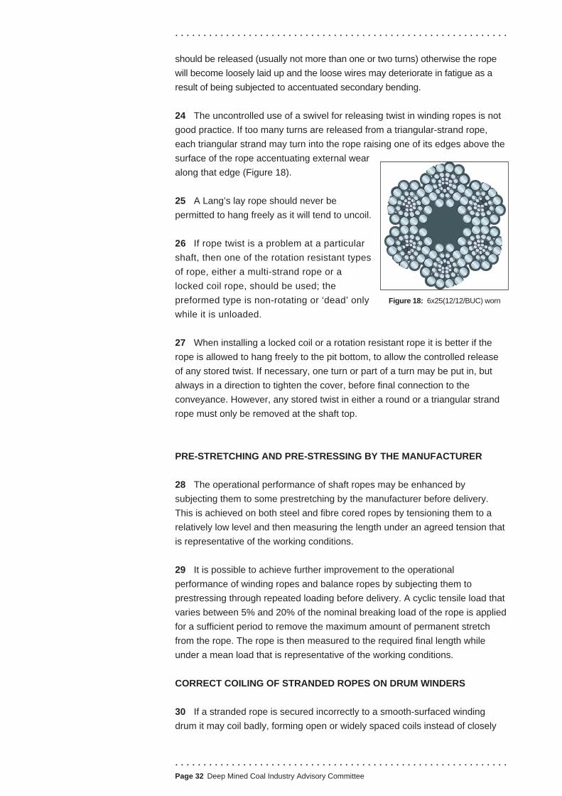
. . . . . . . . . . . . . . . . . . . . . . . . . . . . . . . . . . . . . . . . . . . . . . . . . . . . . . . . . . .
should be released (usually not more than one or two turns) otherwise the rope
will become loosely laid up and the loose wires may deteriorate in fatigue as a
result of being subjected to accentuated secondary bending.
24 The uncontrolled use of a swivel for releasing twist in winding ropes is not
good practice. If too many turns are released from a triangular-strand rope,
each triangular strand may turn into the rope raising one of its edges above the
surface of the rope accentuating external wear
along that edge (Figure 18).
25 A Lang’s lay rope should never be
permitted to hang freely as it will tend to uncoil.
26 If rope twist is a problem at a particular
shaft, then one of the rotation resistant types
of rope, either a multi-strand rope or a
locked coil rope, should be used; the
preformed type is non-rotating or ‘dead’ only Figure 18: 6x25(12/12/BUC) worn
while it is unloaded.
27 When installing a locked coil or a rotation resistant rope it is better if the
rope is allowed to hang freely to the pit bottom, to allow the controlled release
of any stored twist. If necessary, one turn or part of a turn may be put in, but
always in a direction to tighten the cover, before final connection to the
conveyance. However, any stored twist in either a round or a triangular strand
rope must only be removed at the shaft top.
PRE-STRETCHING AND PRE-STRESSING BY THE MANUFACTURER
28 The operational performance of shaft ropes may be enhanced by
subjecting them to some prestretching by the manufacturer before delivery.
This is achieved on both steel and fibre cored ropes by tensioning them to a
relatively low level and then measuring the length under an agreed tension that
is representative of the working conditions.
29 It is possible to achieve further improvement to the operational
performance of winding ropes and balance ropes by subjecting them to
prestressing through repeated loading before delivery. A cyclic tensile load that
varies between 5% and 20% of the nominal breaking load of the rope is applied
for a sufficient period to remove the maximum amount of permanent stretch
from the rope. The rope is then measured to the required final length while
under a mean load that is representative of the working conditions.
CORRECT COILING OF STRANDED ROPES ON DRUM WINDERS
30 If a stranded rope is secured incorrectly to a smooth-surfaced winding
drum it may coil badly, forming open or widely spaced coils instead of closely
. . . . . . . . . . . . . . . . . . . . . . . . . . . . . . . . . . . . . . . . . . . . . . . . . . . . . . . . . . . Page 32 Deep Mined Coal Industry Advisory Committee

. . . . . . . . . . . . . . . . . . . . . . . . . . . . . . . . . . . . . . . . . . . . . . . . . . . . . . . . . . .
. . . . . . . . . . . . . . . . . . . . . . . . . . . . . . . . . . . . . . . . . . . . . . . . . . . . . . . . . . .
.Page 33 Deep Mined Coal Industry Advisory Committee
packed coils. The correct way to fit a rope to a drum is to look at the drum in a
direction towards the shaft in which the winder operates:
(a) a right-hand lay underlap rope should have its dead end secured at the
right-hand flange of the drum;
(b) a right-hand lay overlap rope should have its dead end secured at the left-
hand flange of the drum.
31 There is a simple method of remembering how to fit a right-hand lay rope
to a drum. Looking at the drum in a direction towards the shaft in which the
winding rope operates:
(a) for an underlap rope, extend the right hand towards the under side of the
drum, with the palm facing the drum (ie facing upwards) and with the index
finger pointing towards the shaft. The thumb will then be near to the right-
hand flange of the drum where the dead end of the underlap rope should
be (Figure 19a);
(b) for an overlap rope, extend the right hand towards the top side of the drum,
again with the palm facing the drum (ie facing downwards) and again with
the index finger pointing towards the shaft. The thumb will then be nearest
the left-hand flange of the drum where the dead end of the overlap rope
should be fixed (Figure 19b).
32 For left-hand lay ropes, use the left hand instead of the right. A left-hand
lay underlap rope should have its dead end at the left-hand flange, and an
overlap rope at the right-hand flange.
Direction of rotation
L
R
L
R
Direction of rotation
Figure 19a: underlap -
right-hand lay rope
Figure 19b: overlap -
right-hand lay rope

. . . . . . . . . . . . . . . . . . . . . . . . . . . . . . . . . . . . . . . . . . . . . . . . . . . . . . . . . . .
ROPE TENSIONS IN FRICTION-WINDER ROPES
33 Multi-rope friction-winding installations in the UK operate with the winding
ropes directly connected to the suspension gear of the conveyances and not
through any form of automatic rope tension compensating gear.
34 In order to keep rope tensions approximately equal, it is necessary to keep
the rope tread diameters on the drum as nearly as possible the same. The deeper
A*
check rope marks and
measuremark ropessurface
mid-shaft
pit bottom
* to three drum revolutions equivalent
STAGE 1 STAGE 2 STAGE 3
Distance A should be at least two
the shaft, the more important this is. Large differences in rope tensions can cause
distortion or broken wires in one or more of the winding ropes. Most tower-
mounted friction winders have groove machining equipment installed, and the
grooves can be kept in good order by regular checking and trimming as required.
35 In recent years conveyor belting inserts used in the rope treads of friction
winder drive drums have provided an improved service life to that of timber
inserts and reduce the need for regular trimming of the rope treads.
36 When installing new ropes, engineers should ensure that matched sets of
ropes are used to reduce differential stretch to a minimum. Provided care is taken
to establish the correct rope tread diameters, when the ropes are installed, the
extent of differential tread wear should be small, and it is often possible to avoid
re-trimming grooves during the life of a set of ropes. However, it is necessary to
keep the grooves clear of deposit from the rope. The preferred method of
checking the differences in rope tread diameters and rope tensions on multi-rope
friction winders (Figure 20) is to measure the relative rope travel as follows:
Figure 20: Rope tensions
. . . . . . . . . . . . . . . . . . . . . . . . . . . . . . . . . . . . . . . . . . . . . . . . . . . . . . . . . . . Page 34 Deep Mined Coal Industry Advisory Committee

Rope service requirements
. . . . . . . . . . . . . . . . . . . . . . . . . . . . . . . . . . . . . . . . . . . . . . . . . . . . . . . . . . .
(a) Wind the conveyance from the surface to approximately mid-shaft at a
steady speed of about 3 to 4.5 m/s (10 to 15 ft/s), bringing the conveyance
to rest very gradually without any sudden brake application.
(b) With the conveyance at mid-shaft, mark the ropes at some convenient
place, say ground level in the case of tower winders. The marks can be
made by pencil on a chalk background and should be in a horizontal line;
this is usually achieved by using a straight edge and spirit level, but if site
conditions permit it is advantageous to have permanent straight edge
supports available.
(c) Having marked the ropes, the conveyance is then wound steadily up the
shaft for 2 to 3 drum revolutions, until the rope marks are at some
convenient level such as, in the case of tower winders, near the drum or
deflecting sheaves. The winder is again brought to rest very gradually and
without any sudden brake application. A straight edge should again be
mounted accurately in a horizontal position, so that measurements can
easily be taken of each mark relative to the straight edge to determine
differential rope movement.
37 Any differential movement can be corrected by trimming, in small
increments, the groove or grooves that give the largest rope travel; but if the
grooves are dirty it is advisable to trim them clean first. Following each trimming
the conveyance should be wound through the shaft to bed in the grooves, then
a further check should be made of the measurements following the procedure
outlined above. The point at which trimming becomes necessary is largely
determined by experience, but Table 4 gives guidance on the limits for
differential rope movement. Engineers should ensure that grooves are trimmed
when or before reaching these limits.
Ropes where trouble has been
experienced
First 12 months
Subsequent life
Ropes where trouble has not been
experienced
First 12 months
Subsequent life
Maximum allowable discrepancy
between ropes
6 mm
3 mm
Maximum allowable discrepancy
between ropes
10 mm
6 mm
Note: A new rope will generally tolerate more inaccuracies than one that has been in
service for some time.
Table 4: Tread maintenance guidance - limits on differential rope movement
. . . . . . . . . . . . . . . . . . . . . . . . . . . . . . . . . . . . . . . . . . . . . . . . . . . . . . . . . . .
.Page 35 Deep Mined Coal Industry Advisory Committee

. . . . . . . . . . . . . . . . . . . . . . . . . . . . . . . . . . . . . . . . . . . . . . . . . . . . . . . . . . .
. . . . . . . . . . . . . . . . . . . . . . . . . . . . . . . . . . . . . . . . . . . . . . . . . . . . . . . . . . .Page 36 Deep Mined Coal Industry Advisory Committee
38 Equalisation of the groove tread diameters by this method can reduce
discrepancies in rope travel to within 1 mm of rope travel over a distance of 2 to
3 drum revolutions.
39 In order to assist in making a detailed assessment of this method of
equalising rope tensions and tread diameters, a record should be kept of the
following:
■ the actual measurements and the date of checking;
■ the date of trimming of each groove;
■ measurements after trimming.
40 While other methods have been described in
other guidance this method has been proved,
over a considerable period on many friction
winder installations, to be simple, practical and
reliable.
INSTALLATION AND OPERATION OF
BALANCE ROPES
41 In addition to the general requirements for
shaft ropes given in paragraphs 5 and 6, the
same care must be taken as that with winding
ropes to ensure that the rope does not go slack
as it is led off the reel and that both ends of the
rope remain securely served until they have
been properly capped and fitted to the
conveyances.
42 Multi-strand balance ropes are attached to
the underside of the shaft conveyance by means
of a swivel (Figure 21) to reduce the possibility of
the rope twisting and subsequently becoming
knotted at the loop (Figure 71). In all cases,
mines will need to use a positive means of
preventing the loop from twisting around itself.
Four systems have given satisfactory service:
(a) The baulk system (where there is sufficient
space) - a timber baulk is threaded through the
loop. The baulk is designed to break or lift if the
rope loop lifts too far. The positioning of the
baulk should allow for the loop to rise and fall
during normal operations and also permit the
anchorage
at bottom
of conveyance
plate links
lockable swivel
socket
Figure 21:
Balance rope swivel

. . . . . . . . . . . . . . . . . . . . . . . . . . . . . . . . . . . . . . . . . . . . . . . . . . . . . . . . . . .
. . . . . . . . . . . . . . . . . . . . . . . . . . . . . . . . . . . . . . . . . . . . . . . . . . . . . . . . . . .
.Page 37 Deep Mined Coal Industry Advisory Committee
necessary maintenance operations to be carried out without the need to
disconnect the balance rope.
(b) The open box system (Figure 22) - the loop of a balance rope is
surrounded by a wooden retaining box (a steel structure would damage the
wires). If twin balance ropes are used, a partition is usually fitted to
separate the two loops. The size and position of the box should be such
that it does not interfere with the movement of the rope. Although the rope
striking against timber will cause only light wear or polishing on the outside
of the rope, it can accelerate internal wear by causing nicking between the
strands as they are driven hard together at each impact.
(c) The restricting frame system - an alternative to the open box, it consists
of a number of suitably spaced substantial wooden frames braced together
to control the rope(s) above the loop.
open boarded box
trip wireA
A
trip wire angle should not exceed 26o
conveyance CRS
SECTION A - A
Figure 22: Open box system

. . . . . . . . . . . . . . . . . . . . . . . . . . . . . . . . . . . . . . . . . . . . . . . . . . . . . . . . . . .
(d) The guide hole system - controls each leg of the rope rather than the loop
itself. In this case, a wood-lined slot is used to control the two sides of the
rope and prevent twisting or, alternatively, holes are cut in the sump
platforms to control the rope in all directions. The slots or holes should be
lined with chamfered timbers to allow for both directions of rope travel.
They should be large enough to prevent localised wear on the rope and to
reduce the chance of fallen debris becoming wedged, and obstructing the
passage of the rope.
43 The above systems should be constructed robustly and designed to ensure
that the rope cannot strike or rub on anything other than timber.
44 Paragraph 99 of the ACOP to the 1993 Regulations3 requires the provision
of rising loop protection. A type of monitor that has proved to be effective is a
trip wire through the loop of the balance rope (Figure 22). The wire should be
protected from damage and inadvertent operation from falling debris by a light
structural beam. The electrical switch to which the wire is connected is of a type
that operates in the event of an overtensioned or a broken trip wire.
45 The monitor is connected to the winding engine safety circuit and operates
if the rope loop contacts the trip wire. The position of the monitor above the
normal highest position of the balance rope loop may be between 1 and 1.5 m
but is best finalised by observation, test and experience.
46 Further guidance on balance rope loop monitoring may be found in Safe
manriding in mines report,9 Part 2A, pages 16 and 17 and Part 2B pages 59-61.
47 Balance ropes must not come into contact with debris, water or other
obstructions. Where rates of spillage are high (eg skip shafts) mechanised
means to remove the spillage and automatic monitoring of the spillage level
should be provided.
INSTALLATION AND ATTACHMENT OF GUIDE AND RUBBING ROPES
48 When installing or removing guide or rubbing ropes, the following issues
are particularly relevant to the assessment of risk and the method of carrying
out the work as described in paragraphs 5 and 6.
(a) Constrain the rope to minimise the chance of sudden twisting. If the free
end of a guide or rubbing rope is not properly controlled throughout
removal or installation then it may suddenly twist and create a major
hazard. The procedures should ensure that people are positioned to
minimise the risk to them should the rope move unexpectedly.
(b) Avoid acute rope bending. Guide and balance ropes are constructed of
large wear-resisting wires and a permanent bend in a rope is liable to
suffer rapid and concentrated wear.
. . . . . . . . . . . . . . . . . . . . . . . . . . . . . . . . . . . . . . . . . . . . . . . . . . . . . . . . . . . Page 38 Deep Mined Coal Industry Advisory Committee

. . . . . . . . . . . . . . . . . . . . . . . . . . . . . . . . . . . . . . . . . . . . . . . . . . . . . . . . . . .
(c) The rope should be installed in a smooth, controlled manner to prevent
shock loading.
49 Normally ropes are attached at the headframe by means of a resin or white
metal capping or wedge-type suspension gland. These attachments are
normally above the supporting structure where there is usually adequate space
for lifting, rotating and recapping the ropes. The capping of guide and rubbing
ropes should be in accordance with the instructions given in Technical Annex 3.
. . . . . . . . . . . . . . . . . . . . . . . . . . . . . . . . . . . . . . . . . . . . . . . . . . . . . . . . . . .
.Page 39 Deep Mined Coal Industry Advisory Committee
. . . . . . . . . . . . . . . . . . . . . . . . . . . . . . . . . . . . . . . . . . . . . . . . . . . . . . . . . . .
TECHNICAL ANNEX 3 - THE SERVING AND CAPPING OF SHAFT ROPES
INTRODUCTION
1 There are a number of different ways to terminate the ends of shaft ropes.
Terminations are safety critical and require strict adherence to correct
procedures to quality assure the process and to ensure a satisfactory end
product.
2 This Technical Annex provides significant guidance on those procedures,
but mines will also need to refer to the appropriate manufacturer’s instructions.
3 Serving and capping operations should only be carried out by trained and
experienced people, or under their close supervision.
4 The white metal and resin socket techniques described in this Technical
Annex are also relevant to the termination of underground haulage ropes. The
HSC guidance on haulage ropes1 directs readers to this document for guidance
on those techniques.
5 The term ‘capping’ that appears within this Technical Annex has the
meaning as defined in Safe manriding in mines report Part 1A,9 as follows -
‘The attachment fitted at the end of a steel wire rope by means of which the
rope is coupled to any conveyance or apparatus’.
HAZARDS FROM INADEQUATE CAPPING PROCEDURES
6 It is essential that all personnel associated with the capping operation are
aware of the potential hazards from improper capping procedures.
7 The most obvious hazard that can arise is the release of a load due to
failure of the capping which may lead to serious injury or death of anyone being
conveyed through the shaft or those in the vicinity of the winding equipment.
8 Premature failure of the capping can be caused by the following:
(a) incorrect choice and specification of socket/gland;
(b) incorrect preparation of brush and socket/gland;
(c) incorrect positioning of the brush and alignment of socket/gland and rope;
(d) incorrect capping procedure.
Capping materials present hazards in themselves, and should be included
in the overall assessment of risks, as required by the provisions of the Control
. . . . . . . . . . . . . . . . . . . . . . . . . . . . . . . . . . . . . . . . . . . . . . . . . . . . . . . . . . . Page 40 Deep Mined Coal Industry Advisory Committee
9

Serving and clamping
Serving
Size of serving wire
. . . . . . . . . . . . . . . . . . . . . . . . . . . . . . . . . . . . . . . . . . . . . . . . . . . . . . . . . . .
of Substances Hazardous to Health Regulations 2002 (COSHH).10 Work
should be organised to minimise workers’ exposure to potentially harmful
substances, including vapour and fume.
ROPE SERVING
10 Whenever any type of shaft rope is cut, it is essential to take effective
precautions in order to prevent any loosening of the wires during the cutting
and capping operations. To do this the rope must be securely served before
cutting off the old capping, or excess length of new rope, and, where
appropriate, clamped on both sides of the proposed cutting point X in
(Figure 23a). Tinned annealed serving wire of the size shown in Table 5
should be used. On no account should copper wire be used as it is liable to
cause corrosion.
11 A serving is a wrapping of wire laid tightly around a rope to prevent its
wires from unlaying or moving and slackening when the rope is cut between
two adjacent servings. A serving would be insufficient, particularly on a larger
rope, if it consists only of a few turns of wire, string or insulating tape wrapped
around the rope in the form of open or partly overlapping coils.
12 The correct size and type of serving has to be applied tightly to the rope,
under proper tension, and in neatly laid parallel coils that are in hard contact
with one another, otherwise they could move sideways and become slack.
13 Serving wire must be soft to readily take a permanent bend, so that it fits
closely to the shape of the rope; otherwise the rope will move and
accommodate itself to the shape of the serving. A good serving on a six-strand
rope will appear somewhat six-sided.
14 Table 5 gives the recommended sizes of serving wire for ropes of 13 mm
diameter and greater:
Rope diameter (mm)
13 to 22
22 to 38
Larger than 38
Size of serving wire (mm)
1.3
1.6
1.8
Table 5: Recommended sizes of serving wire
15 Full locked coil and half-locked coil ropes should only be served using
single serving wire. A stranded wire serving must never be used to serve those
types of rope as it may collapse and flatten in places, and consequently
become slack allowing the rope to loosen.
. . . . . . . . . . . . . . . . . . . . . . . . . . . . . . . . . . . . . . . . . . . . . . . . . . . . . . . . . . .
.Page 41 Deep Mined Coal Industry Advisory Committee
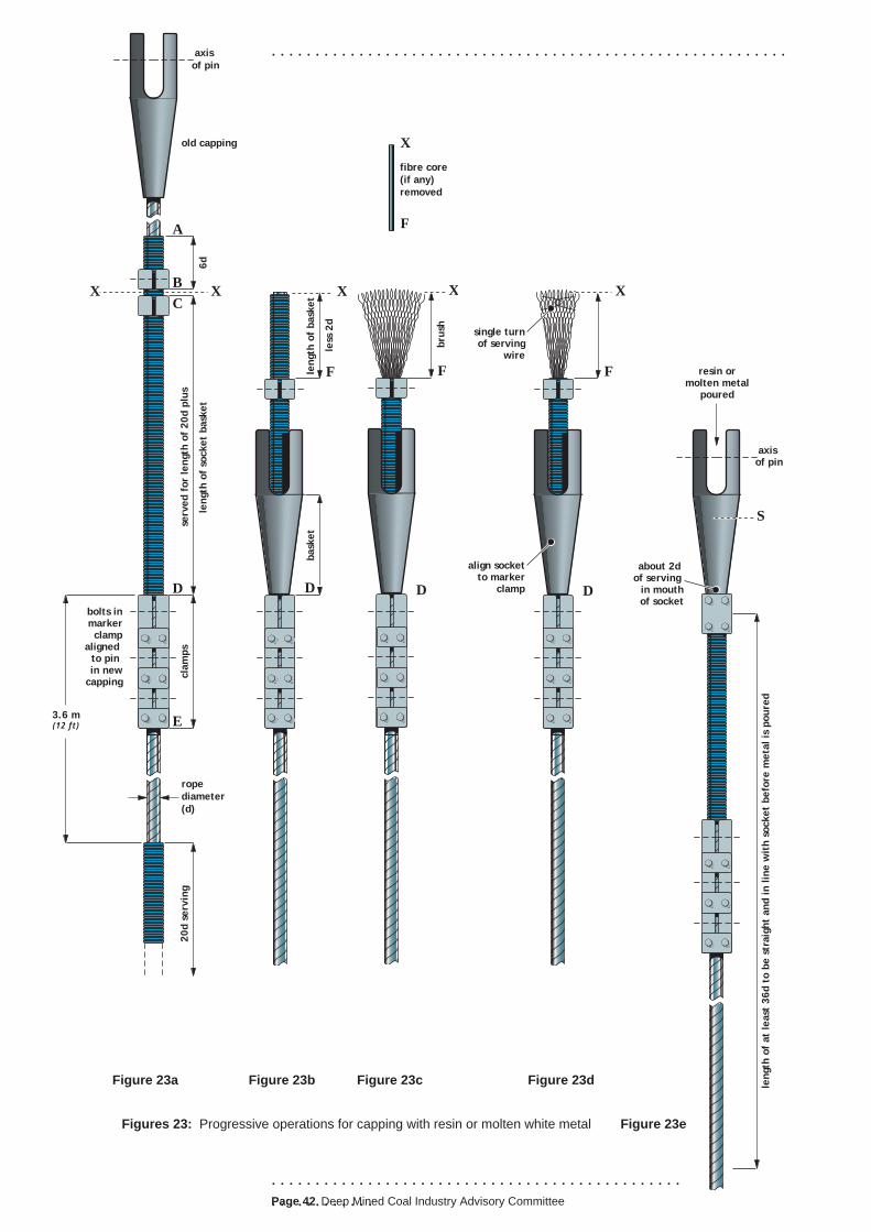
. . . . . . . . . . . . . . . . . . . . . . . . . . . . . . . . . . . . . . . . . . . . . . . . . . . . . . . . . . .
. . . . . . . . . . . . . . . . . . . . . . . . . . . . . . . . . . . . . . . . . . . . . . .
. . . . . . . . . . . .Page 42 Deep Mined Coal Industry Advisory Committee
bask
et
length
of
bask
et
less
2d
X
F
D
old capping
serv
ed f
or
length
of
20d p
lus
cla
mps
20d s
erv
ing
length
of
socket
bask
et
6d
axis
of pin
rope
diameter
(d)
3.6 m(12 ft)
bolts inmarkerclamp
aligned to pin in new
capping
XB
C
D
A
X
E
single turnof serving
wire
align socketto marker
clamp D
X
F
bru
sh
fibre core
(if any)
removed
X
F
X
F
D
axis of pin
resin ormolten metal
poured
length
of
at
least
36d t
o b
e s
traig
ht
and in lin
e w
ith s
ocket
befo
re m
eta
l is
poure
d
S
about 2d of serving
in mouthof socket
Figures 23: Progressive operations for capping with resin or molten white metal
Figure 23a Figure 23b Figure 23c Figure 23d
Figure 23e
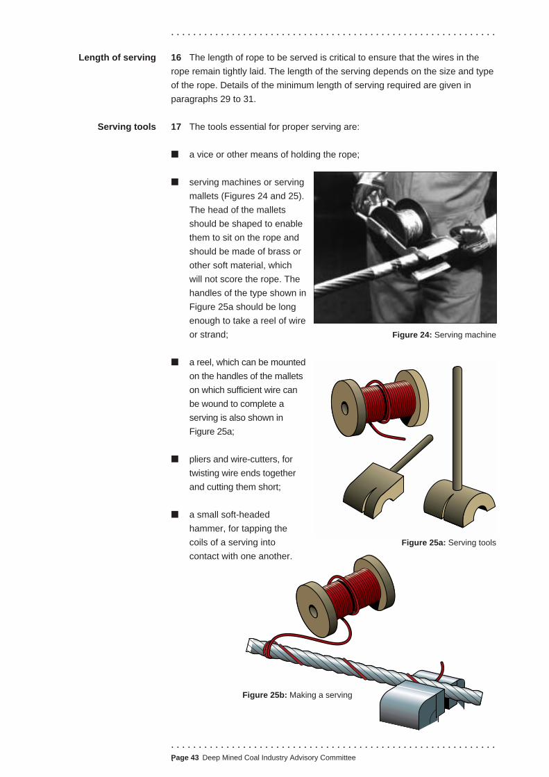
. . . . . . . . . . . . . . . . . . . . . . . . . . . . . . . . . . . . . . . . . . . . . . . . . . . . . . . . . . .
. . . . . . . . . . . . . . . . . . . . . . . . . . . . . . . . . . . . . . . . . . . . . . . . . . . . . . . . . . .
.Page 43 Deep Mined Coal Industry Advisory Committee
16 The length of rope to be served is critical to ensure that the wires in the
rope remain tightly laid. The length of the serving depends on the size and type
of the rope. Details of the minimum length of serving required are given in
paragraphs 29 to 31.
17 The tools essential for proper serving are:
■ a vice or other means of holding the rope;
■ serving machines or serving
mallets (Figures 24 and 25).
The head of the mallets
should be shaped to enable
them to sit on the rope and
should be made of brass or
other soft material, which
will not score the rope. The
handles of the type shown in
Figure 25a should be long
enough to take a reel of wire
or strand;
■ a reel, which can be mounted
on the handles of the mallets
on which sufficient wire can
be wound to complete a
serving is also shown in
Figure 25a;
■ pliers and wire-cutters, for
twisting wire ends together
and cutting them short;
■ a small soft-headed
hammer, for tapping the
coils of a serving into
contact with one another.
Length of serving
Serving tools
Figure 24: Serving machine
Figure 25a: Serving tools
Figure 25b: Making a serving

. . . . . . . . . . . . . . . . . . . . . . . . . . . . . . . . . . . . . . . . . . . . . . . . . . . . . . . . . . .
. . . . . . . . . . . . . . . . . . . . . . . . . . . . . . . . . . . . . . . . . . . . . . . . . . . . . . . . . . .Page 44 Deep Mined Coal Industry Advisory Committee
18 This is the type of serving used in conditions where soldering is not
permitted for stranded ropes; for example, below ground in a mine where a
potentially explosive atmosphere may be present.
19 The first part of the serving wire is laid
along the length of rope to be served, and the
remaining wire is then wound tightly over it in
coils so that the two ends of the serving wire
finish at the same place. They can be twisted
together and cut off short to complete the
serving.
20 To make such a serving, the free end of
the serving wire is paid out for about 0.5 m
and its end clamped in a vice together with
the rope (Figure 25b). Next, the paid-out wire
is laid from the vice along the rope to the far
end of the rope length to be served. The wire
should be laid in the ‘valley’ between two
strands such that it spirals around the rope.
This part of the wire is known as the ‘buried
wire’.
21 The paid-out wire should be bent to lay at
right-angles to the rope and turned twice
around it, so that it lays on top of the buried
wire to form the beginning of the serving
(Figure 25b). The serving mallet is then
placed on the rope, on top of these two turns
(Figure 25c), and the wire leading from these
turns passed over the top edge of the mallet
and round the back of the handle (Figure 25c).
The wire is passed over the top edge of the
mallet again, under the rope, up over the
other edge of the mallet and the reel placed
on the handle of the serving mallet (Figure
25d), and the reel turned to take up the slack
wire. The mallet is then rotated round the
rope in the same direction as the serving
(Figure 25e). The drag or friction of the wire
passing round the mallet handle will ensure
that the serving is applied tightly to the rope,
under proper tension.
22 It is essential to control the turning of the reel on the handle so as to pay
out wire only at the rate at which it is needed; slack wire will mean slack
serving. Each turn of serving wire should be tight to the rope and should be in
hard contact with one another. A method of guiding the wire into close packed
The ordinary or buried
wire serving
Figure 25c: Making a serving
Figure 25d: Making a serving
Figure 25e: Making a serving

. . . . . . . . . . . . . . . . . . . . . . . . . . . . . . . . . . . . . . . . . . . . . . . . . . . . . . . . . . .
. . . . . . . . . . . . . . . . . . . . . . . . . . . . . . . . . . . . . . . . . . . . . . . . . . . . . . . . . . .
.Page 45 Deep Mined Coal Industry Advisory Committee
coils is to cut a guide-groove for the wire in the head of the mallet (Figure 25a).
If the turns are not in hard contact it will be necessary to tap them more closely
together with a soft-headed hammer.
23 When serving is complete, the wire from the final coil and that from the
buried wire should be twisted together, pulled tight and twisted further to keep
them tight. The ends should then
be trimmed to leave about four
twists, (Figure 25f). Finally, the
twisted end should be tapped
down with a hammer so that it
lays neatly against the rope in a
valley between two strands.
24 This is the preferred serving where soldering is permitted. With this method
wire is served directly on to the rope, without any buried wire being present, so
that the two ends of the serving wire lie at opposite ends of the serving. The
type of serving machine used is shown in Figure 24.
25 To apply a wiped serving, the starting end of the wire is reeved from the
bobbin of the serving machine and fastened to a nearby object or lashed to the
rope with yarn or tape so that the fastened end is close to the left-hand. The
serving machine is passed around the rope until the wire holds it in position
where the cut is to be made.
26 For a right-hand lay rope the serving is then applied by raising the handle
of the machine upwards and towards the body, passing it over the rope and
down away from the body, moving to the right. For a left-hand lay rope the
starting end of the wire is fastened such that it is close to the right-hand and the
same method is applied but the machine moves to the left. Adopting the
appropriate method to suit the lay of the rope will ensure that the serving
applied is coiled in the opposite direction to the rope lay. This procedure
ensures that if the rope tends to unlay then it will tighten the serving.
27 When the serving is about 150 mm long its surface should be thoroughly
cleaned in preparation for soldering. Coraline flux or powdered rosin is then
applied. Baker’s fluid or killed spirit should never be used as a flux because
they can penetrate between the turns of the serving and corrode the rope.
The coils of wire are then soldered along one side of the rope using tinman’s
solder; the hot soldering iron being passed several times across the surface
of the serving so that the solder flows into the gaps between the turns of
serving wire.
28 The length of rope to be served depends on the object of the serving and
on the size and type of the rope. A stranded rope exerts only a moderate
bursting force on a serving. A large locked coil rope will exert a considerable
pressure on the serving, and should the serving burst, the rope will unlay itself
violently over a long length.
The soldered or
wiped serving
Figure 25f: Completed serving

. . . . . . . . . . . . . . . . . . . . . . . . . . . . . . . . . . . . . . . . . . . . . . . . . . . . . . . . . . .
29 For stranded ropes apply two or more short servings at least 6 x rope
diameter (d) in length to secure the rope end.
30 In the case of locked coil ropes, more stringent precautions are necessary
than with other rope types. With locked coil ropes, the length AD (Figure 23a) is
a continuous length of serving at least 26 x rope diameter (d), plus the length of
the socket basket and the length BC needed for cutting the rope at point X. The
serving length AB (Figure 23a) on the part of the rope to be discarded should
be at least 6d in length.
31 On the part to be retained, the serving CD (Figure 23a) should have an
overall length of not less than 20d, plus the length of the socket basket. A
further length of serving, at least 20d in length, should be applied lower down
the rope about 3.6 m from the first serving. Then, as an extra safeguard, six
clamps should be fitted between these two lengths of serving (D to E in Figure
23a). Each served length must be of the soldered type but need not necessarily
be composed of one continuous length of wire.
CAPPING WITH RESIN OR MOLTEN WHITE METAL
32 This part of the guidance should be applied to the capping of steel wire
ropes using sockets (or glands) specified in the Reference section at the back of
this book whether they are capped at the mine or rope manufacturer’s works.
33 The statutory requirements for capping ropes on winding and haulage
apparatus are governed by the 1993 Regulations2 and the Coal and Other Mines
(Shafts, Outlets and Roads) Regulations 196011 respectively. In particular,
regulation 17 of the 1993 Regulations and ACOP2,3 make provision for:
■ the capping of ropes used in winding apparatus;
■ the appointment of competent people; and
■ the writing of reports by such people.
The remainder of this Annex provides further guidance on rope capping.
34 Resin and white metal are excellent capping mediums, are the most widely
used, and work on the principle of gripping the wires individually in a single
cone of resin or white metal within a conical socket. When properly made and
in BS or NCB standard sockets, this type of capping is at least as strong as the
rope. The progressive operations for capping as illustrated in Figure 23, are
detailed below, and should be strictly observed to ensure that a reliable capping
is obtained.
. . . . . . . . . . . . . . . . . . . . . . . . . . . . . . . . . . . . . . . . . . . . . . . . . . . . . . . . . . . Page 46 Deep Mined Coal Industry Advisory Committee

. . . . . . . . . . . . . . . . . . . . . . . . . . . . . . . . . . . . . . . . . . . . . . . . . . . . . . . . . . .
Cutting
Preparing the brush
CUTTING THE ROPE AND FORMING THE BRUSH
35 The six clamps referred to in paragraph 31, should be the half-clamp, two-
bolt type with a machined bore, with a 3 mm gap between the half clamps when
tightened on the rope. Set the clamps on the rope alternately at right angles to
one another, the clamp nearest the old capping being used as a marker clamp,
if required, with the bolts in the required direction of the pin in the new socket.
36 Before cutting the rope, set temporary clamps at B and C (Figure 23a)
immediately on either side of the cutting point X.
37 Cut the rope at X by any suitable method which does not disturb the wires.
With percussive or shearing methods special care is required to avoid any
disturbance to the serving or to the wires in the rope. Flame cutting equipment
must not be used as the heat may damage the rope and the serving.
38 After cutting the rope, remove the temporary clamp at C and thread the
new socket (to NCB Specification 465/196512 for a winding rope) over the end
of the rope, pushing it along the serving as far as the marker clamp D (Figure
23b). Before threading the socket onto the rope, make sure that the inside of
the socket basket is clean and dry and that there are no rough places on the
radius in the socket mouth. Apply another clamp over the serving at F so that
the length XF (Figure 23b) is equal to the length of the basket less about 2 x
rope diameter (d). The value of about 2d is recommended so that sufficient
length of served rope will be inserted into the mouth of the socket to ensure that
the point at which the wires begin to separate to form the brush will be well
embedded in the capping medium, rather than being in hard contact with the
small end of the conical bore of the socket.
39 Remove the part of the long serving between X and F (Figure 23b). With
large locked coil ropes care should be taken with this operation, as the rope
wires will tend to open with some force, and a clamp at F is essential on all
shaft ropes to ensure that the rope does not loosen beyond this point. Open the
rope over the length XF.
40 Separate all the wires but do not straighten them, and take great care to
avoid bending or twisting any wire too sharply at F (Figure 23c), otherwise
deformed wires may break in fatigue during service. If there is a fibre core it
must be cut at F and removed.
41 When opening the brush on locked coil ropes it is particularly important to
ensure that there are no bends or twists in the outer full lock wires, because
these may dramatically reduce both the fatigue life of those wires and therefore
the life of the capping as a whole.
42 Investigations into brushing standards on locked coil ropes across the
industry identified that there was only one correct method by which the outer
layer wires could be opened out. This method depends on whether the cross
. . . . . . . . . . . . . . . . . . . . . . . . . . . . . . . . . . . . . . . . . . . . . . . . . . . . . . . . . . .
.Page 47 Deep Mined Coal Industry Advisory Committee
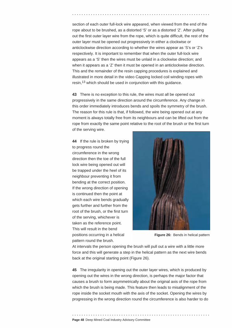
. . . . . . . . . . . . . . . . . . . . . . . . . . . . . . . . . . . . . . . . . . . . . . . . . . . . . . . . . . .
section of each outer full-lock wire appeared, when viewed from the end of the
rope about to be brushed, as a distorted ‘S’ or as a distorted ‘Z’. After pulling
out the first outer layer wire from the rope, which is quite difficult, the rest of the
outer layer must be opened out progressively in either a clockwise or
anticlockwise direction according to whether the wires appear as ‘S’s or ‘Z’s
respectively. It is important to remember that when the outer full-lock wire
appears as a ‘S’ then the wires must be unlaid in a clockwise direction; and
when it appears as a ‘Z’ then it must be opened in an anticlockwise direction.
This and the remainder of the resin capping procedures is explained and
illustrated in more detail in the video Capping locked coil winding ropes with
resin,13 which should be used in conjunction with this guidance.
43 There is no exception to this rule, the wires must all be opened out
progressively in the same direction around the circumference. Any change in
this order immediately introduces bends and spoils the symmetry of the brush.
The reason for this rule is that, if followed, the wire being opened out at any
moment is always totally free from its neighbours and can be lifted out from the
rope from exactly the same point relative to the root of the brush or the first turn
of the serving wire.
44 If the rule is broken by trying
to progress round the
circumference in the wrong
direction then the toe of the full
lock wire being opened out will
be trapped under the heel of its
neighbour preventing it from
bending at the correct position.
If the wrong direction of opening
is continued then the point at
which each wire bends gradually
gets further and further from the
root of the brush, or the first turn
of the serving, whichever is
taken as the reference point.
This will result in the bend
positions occurring in a helical
pattern round the brush.
At intervals the person opening the brush will pull out a wire with a little more
force and this will generate a step in the helical pattern as the next wire bends
back at the original starting point (Figure 26).
Figure 26: Bends in helical pattern
45 The irregularity in opening out the outer layer wires, which is produced by
opening out the wires in the wrong direction, is perhaps the major factor that
causes a brush to form asymmetrically about the original axis of the rope from
which the brush is being made. This feature then leads to misalignment of the
rope inside the socket mouth with the axis of the socket. Opening the wires by
progressing in the wrong direction round the circumference is also harder to do
. . . . . . . . . . . . . . . . . . . . . . . . . . . . . . . . . . . . . . . . . . . . . . . . . . . . . . . . . . . Page 48 Deep Mined Coal Industry Advisory Committee

. . . . . . . . . . . . . . . . . . . . . . . . . . . . . . . . . . . . . . . . . . . . . . . . . . . . . . . . . . .
than opening them in the correct direction and the extra difficulty tends to result
in the wires being bent at sharper angles, sometimes introducing twists into the
wires, which can have dramatic effects on capping life.
46 The presence of sharp bends or twists in individual wires influences the
fatigue life of a capping, so when making a brush such features must be
avoided. The transition from rope to brush should be as smooth as possible.
The smoothness of the transition is determined by the angle through which the
outer layer wires are opened out; a small angle
optimises fatigue life, while opening the wires to a
wider angle facilitates easier degreasing of the wires
in the second and inner layers.
47 For a maximum service life a narrow angle and
smooth transition are required (Figure 27). The
small amount of lubricant left on the inner wires very
close to the root of the brush will not have a major
effect on the strength of the capping. The shape of
Figure 27: Narrow angle the brush at this point is the more important factor.
and smooth transition However, the inner layer wires should be thoroughly
degreased for the rest of the length of the brush.
48 While the opening out of the
outer layer wires at the root of the
brush is the factor that influences the
life of a capping more than anything
else, the overall shape of the brush
and especially its symmetry about the
rope axis can have a detrimental effect if not properly controlled
(Figure 28). When the outer full-lock wires are opened out they
should be left with as much of their original helical form as
practical (Figure 29). Attempts to straighten these wires and to
make them lie parallel with the axis of the rope increases the
possibility that one or more of them will twist over as they are
being straightened and it can introduce unnecessary bends,
often quite sharp, close
to the root of the brush
(Figure 30). With the
wires retaining as much
of their original helical
shape as possible, the
Figure 28: Control over
shape of brush
brush usually forms into either a ‘tulip’
or ‘daffodil’ shape depending on lay
direction of the outer layer and the
construction of the rope. The actual
shape adopted is not a problem as long
as the shape remains symmetrical
about the axis of the rope. Figure 30: Unnecessary bends
Figure 29: Outer full-lock wires retaining
original helical form
. . . . . . . . . . . . . . . . . . . . . . . . . . . . . . . . . . . . . . . . . . . . . . . . . . . . . . . . . . .
.Page 49 Deep Mined Coal Industry Advisory Committee

. . . . . . . . . . . . . . . . . . . . . . . . . . . . . . . . . . . . . . . . . . . . . . . . . . . . . . . . . . .
Figure 31:
Assymetric shape
49 If the overall shape of the brush is asymmetric, which is usually caused by
the irregular opening out of the full-lock wires at the root of the brush, then, as
the brush is drawn back into the socket it will be forced over towards one side,
possibly affecting the centring of the rope in the socket mouth (Figure 31).
In most cases even if the centring is not affected, the length of rope which is
inside the socket mouth will be forced out of alignment with the axis of the
socket (Figure 32) and it will emerge from the socket at a slight angle to the axis
of the socket.
50 Tests made on a small number
of discarded cappings from coal
mines have shown that such
misalignment of the rope inside the
socket mouth introduces additional
stresses into the wires on one side
of the rope and, if tested up to the
breaking load of the rope, failure will
usually occur inside the socket neck
under the first turn of the serving at
the root of the brush at a load which
can be 5-10% below the actual
breaking load of the rope.
51 Under fatigue loading
conditions the extra bending stresses generated by the misalignment will
severely reduce the fatigue life of the capping, perhaps halving the potential
fatigue life obtainable under the same test conditions with a well made capping.
52 In a locked coil rope the outer layer wires contribute about 30% of the total
strength of the rope so it is important that individually these wires should be
separated from each other and as fully enveloped by the resin or white metal as
Figure 32: Forced out of alignment
possible. Examinations of discarded
cappings revealed that there have
been some cones where the outer
layer wires had been opened out in
groups of two, three, and even four or
five wires, which lay parallel and
touching each other for almost the full
length of the cone (Figure 33). Such
poor separation could have a
detrimental effect on the pull out
strength of these wires from the cone.
Although the capping medium will grip
each group as a whole this grip will be
less than the sum of the gripping forces
which would have been applied if the
wires had been separated. Figure 33: Grouping of outer layer wires
. . . . . . . . . . . . . . . . . . . . . . . . . . . . . . . . . . . . . . . . . . . . . . . . . . . . . . . . . . . Page 50 Deep Mined Coal Industry Advisory Committee

. . . . . . . . . . . . . . . . . . . . . . . . . . . . . . . . . . . . . . . . . . . . . . . . . . . . . . . . . . .
53 If a rope is held in the horizontal position while making the brush then the wires
on the top of the rope tend to be opened out at a greater angle to those underneath it,
because it is easier to prize a wire upwards than downwards with the rope in this
position. When the end of the rope is placed in a frame at an angle of about 45o to the
horizontal then the wires on both the top and underside of the rope tend to be opened
out in a more symmetrical manner. This brushing position has now been adopted at
many mines and is demonstrated in the video referred to in paragraph 42.13
54 Where necessary, rearrange the wires in the main part of a brush to make
it as symmetrical as possible before it is finally drawn into the socket. This
could give a useful increase in the fatigue life by alleviating or reducing
misalignment of the rope inside the socket mouth.
55 To ensure that the white metal or
resin securely grips the wires,
thoroughly clean each wire of all traces
of lubricant or dirt with a water-soluble
degreasing fluid or a non-flammable
organic solvent. Paraffin must not be
used. During this operation keep the
brush in a downward position (Figure
34) to make sure no degreasing fluid Figure 34: Cleaning the brush
enters the unopened part of the rope
as this may affect its internal lubricant. The brush should remain in a downward
position until all the wires are completely dry.
56 By means of a single turn of serving wire placed around
the brush near its top end (Figures 23d and 35) or, in the
case of a large rope, two or three single or double-turn
servings spaced along the length of the brush where required;
draw the cleaned wires of the brush slightly together just
enough to prevent appreciable lengths of the outermost wires
from touching the inner surface of the socket when the socket
is pulled onto the brush. This will ensure that the wires are
Figure 35: Single serving wire effectively embedded in the resin or white metal.
57 The temporary clamp at F (Figure 23d) can now be removed. Before the
socket is pulled into position it should be rotated on the rope until orientated
similarly to the marker clamp at D
(Figure 23d). It can then be drawn
carefully over the prepared brush by
any means which provide a direct axial
pull. Figure 36 shows a suitable
method. The socket is then pulled onto
the brush so that the ends of the wires
are approximately 5 mm above the top
of the socket basket at S (Figure 23e);
this leaves a length of about 2d of the Figure 36: Socket pulled into place
. . . . . . . . . . . . . . . . . . . . . . . . . . . . . . . . . . . . . . . . . . . . . . . . . . . . . . . . . . .
.Page 51 Deep Mined Coal Industry Advisory Committee

. . . . . . . . . . . . . . . . . . . . . . . . . . . . . . . . . . . . . . . . . . . . . . . . . . . . . . . . . . .
serving contained within the mouth of the socket. The 5 mm protrusion of the
wires above the top of the socket basket will allow easier detection of any
movement of the wires relative to the resin or white metal during the pouring
operation and use of the rope. However, care is needed to ensure that the wire
ends do not foul the mating unit which will be subsequently connected to the
pin of the socket.
FORMING A RESIN CAPPING
58 The following guidance has been prepared in conjunction with the video
previously mentioned in paragraph 42.13 The video shows in great detail the
forgoing procedure for preparing the brush and the procedure for making a
resin capping that follows. It is strongly recommended that the video is made
available to people involved in rope capping operations for both training and
reference purposes.
59 The only resins used should be polyester-based proprietary resin systems
that include an inorganic filler and a curing agent. Resin systems need to have
a minimum ultimate compressive strength of 90 N/mm2 and a minimum ultimate
shear strength of 15 N/mm2.
HEALTH AND SAFETY REQUIREMENTS DURING RESIN CAPPING
60 Risk assessments under the COSHH Regulations10 and the Management
of Health and Safety Regulations14 will define the appropriate working
procedures for safe use of resin systems for rope capping. The advice given in
this section serves only as a general guide.
61 Information on the hazards of any resin capping system can be found in
the supplier’s health and safety datasheet.
62 A resin capping kit contains a polyester-based resin which is classified as a
flammable substance. The resin component contains styrene, the vapours of
which can be irritating to the eyes and respiratory system, and if inhaled in high
concentrations may cause symptoms associated with solvent intoxication,
including drowsiness. The maximum exposure level (MEL) for styrene is
specified in EH40 produced in accordance with the provisions of the COSHH
Regulations.10
63 It is essential to use resin capping kits only in well-ventilated areas, using
working procedures that minimise personal exposure to vapours. Most of the
vapours are given off from the mixing vessel rather than from the resin inside
the socket. To reduce the vapour level when working in a closed or relatively
confined space, the mixing vessel should be removed from the work area after
pouring. Where work is carried out on a frequent or regular basis, air monitoring
may be necessary to ensure that styrene levels are as low as possible.
. . . . . . . . . . . . . . . . . . . . . . . . . . . . . . . . . . . . . . . . . . . . . . . . . . . . . . . . . . . Page 52 Deep Mined Coal Industry Advisory Committee

. . . . . . . . . . . . . . . . . . . . . . . . . . . . . . . . . . . . . . . . . . . . . . . . . . . . . . . . . . .
64 Uncured resin is an irritant and contact with eyes and skin should be avoided,
for instance by careful mixing and pouring of the resin. Those mixing and working
with the resin should wear appropriate gloves, goggles and other protective
equipment to minimise the possibility of direct contact. Those handling the powder
component should do so in a manner that minimises the chance of dust being
raised into the air. They should wear dust masks for additional protection.
65 Polyester resin is a flammable substance and should be used away from
sources of ignition. Particular attention needs to be paid to the storage of resin
capping kits.
Material 66 Resin kits contain the exact proportions of ingredients required to achieve
full strength, and for this reason packages should never be sub-divided. The
ingredients should be mixed and used in accordance with the manufacturer’s
instructions. The kit should only be opened immediately before mixing.
67 The only resin system currently in use in UK mines is the Wirelock system.
Wirelock resin kits are marked ‘wire rope capping’ and are available in four
sizes to produce after setting the following volumes:
■ 500 cc - green container
■ 1000 cc - yellow container
■ 1700 cc - blue container
■ 3400 cc - red container
68 The kits are pre-measured and consist of two containers; one with liquid
resin and one with filler/catalyst powder. The two containers are packed in an
outer plastic container, which is used for mixing, together with a stirrer, silicone
release agent and plasticine.
69 The kits have a shelf life of 18 months. Expiry dates are marked clearly on
the containers. Date expired kits should not be used.
70 The expiry date applies only when the kit has been stored in suitable
conditions. To ensure that the kits are not adversely affected by storage, they
should be stored in a dry place at a temperature between 10oC and 25oC and
away from any source of direct heat.
PREPARATION, CLEANING AND POSITIONING OF THE ROPE AND
SOCKET - ADDITIONAL GUIDANCE FOR RESIN CAPPING
71 The preparation, cleaning and positioning of the rope, socket and brush
should be carried out in accordance with the procedures described previously.
Additional guidance is given overleaf.
. . . . . . . . . . . . . . . . . . . . . . . . . . . . . . . . . . . . . . . . . . . . . . . . . . . . . . . . . . .
.Page 53 Deep Mined Coal Industry Advisory Committee

Rope service requirements
. . . . . . . . . . . . . . . . . . . . . . . . . . . . . . . . . . . . . . . . . . . . . . . . . . . . . . . . . . .
72 The served length of rope inside the socket or gland should be as shown in
Table 6 below, where d is the rope diameter:
Socket/gland type Served length
British Coal Specification 465:1965- Winding, balance and 2 x d
haulage rope sockets
British Coal Specification 461:1965- Haulage rope sockets 1 x d
British Coal Specification 353:1966- Haulage rope sockets 2 x d
Balance rope sockets to BCC MECH/CIRC(81)82 1 x d
Guide/rubbing rope suspension glands having a ratio of tapered 1 x d
length to rope diameter of 6:1 and above
Safety block on wedge type capping 0.5 x d
Table 6: Served rope lengths for socket/gland types
73 Use a tinned or galvanised annealed mild steel or soft iron single
serving wire (not a strand) of the size shown in Table 5. Exceptionally, when
using sockets to BCC Specification 353 and 461 for haulage ropes a serving
wire of 1 mm diameter should be used due to the restricted clearance in the
socket neck.
74 Before the socket is threaded on to the rope, the inside of the socket
should be very lightly smeared with some of the silicone release agent supplied
with the kit. This will reduce the tendency of the resin to bond to the socket
basket. When the socket is pulled over the brush it is important to minimise any
rotation which could cause the wires to scrape off the silicone release agent
from the socket basket. This could produce a build-up of silicone release agent
on the wires which would reduce the grip of the resin on these wires. It should
be noted that it is not necessary to use the whole tube of silicone release agent
supplied with the kit.
75 The wires of the brush should be distributed as evenly as practicable
within the socket basket. Special precautions are necessary when capping
half-lock guide ropes with resin. Stress cracking of the resin cone can occur
at the curing stage if the outer wires are allowed to press heavily against the
bore of the socket/gland at the wide end of the basket. To prevent this a
space of approximately one wire diameter should be maintained so far as
practicable between the wall of the socket and any wire at the end of the
socket.
76 Resin leakage may cause voids in the cone and lead to unsupported
wires (Figures 37(a) and 37(b)). It is therefore imperative that no leaks
. . . . . . . . . . . . . . . . . . . . . . . . . . . . . . . . . . . . . . . . . . . . . . . . . . . . . . . . . . . Page 54 Deep Mined Coal Industry Advisory Committee
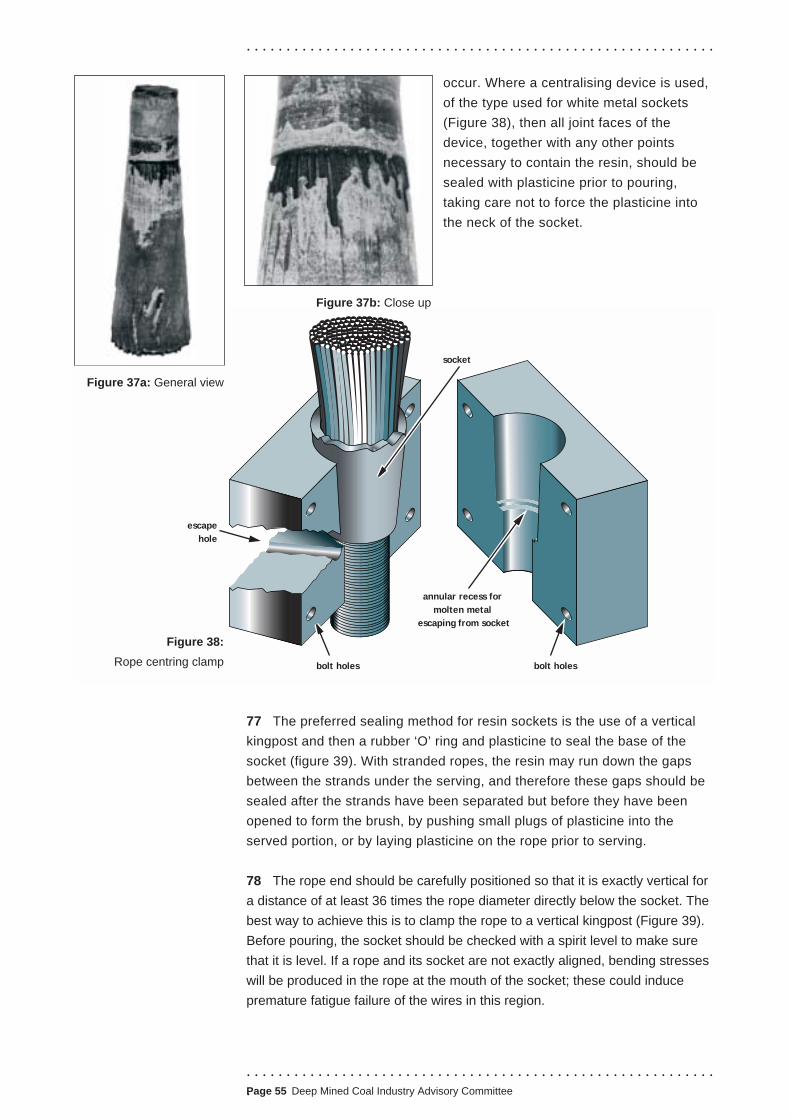
. . . . . . . . . . . . . . . . . . . . . . . . . . . . . . . . . . . . . . . . . . . . . . . . . . . . . . . . . . .
. . . . . . . . . . . . . . . . . . . . . . . . . . . . . . . . . . . . . . . . . . . . . . . . . . . . . . . . . . .
.Page 55 Deep Mined Coal Industry Advisory Committee
occur. Where a centralising device is used,
of the type used for white metal sockets
(Figure 38), then all joint faces of the
device, together with any other points
necessary to contain the resin, should be
sealed with plasticine prior to pouring,
taking care not to force the plasticine into
the neck of the socket.
77 The preferred sealing method for resin sockets is the use of a vertical
kingpost and then a rubber ‘O’ ring and plasticine to seal the base of the
socket (figure 39). With stranded ropes, the resin may run down the gaps
between the strands under the serving, and therefore these gaps should be
sealed after the strands have been separated but before they have been
opened to form the brush, by pushing small plugs of plasticine into the
served portion, or by laying plasticine on the rope prior to serving.
78 The rope end should be carefully positioned so that it is exactly vertical for
a distance of at least 36 times the rope diameter directly below the socket. The
best way to achieve this is to clamp the rope to a vertical kingpost (Figure 39).
Before pouring, the socket should be checked with a spirit level to make sure
that it is level. If a rope and its socket are not exactly aligned, bending stresses
will be produced in the rope at the mouth of the socket; these could induce
premature fatigue failure of the wires in this region.
escape
hole
socket
annular recess for
molten metal
escaping from socket
bolt holes bolt holes
Figure 37a: General view
Figure 38:
Rope centring clamp
Figure 37b: Close up
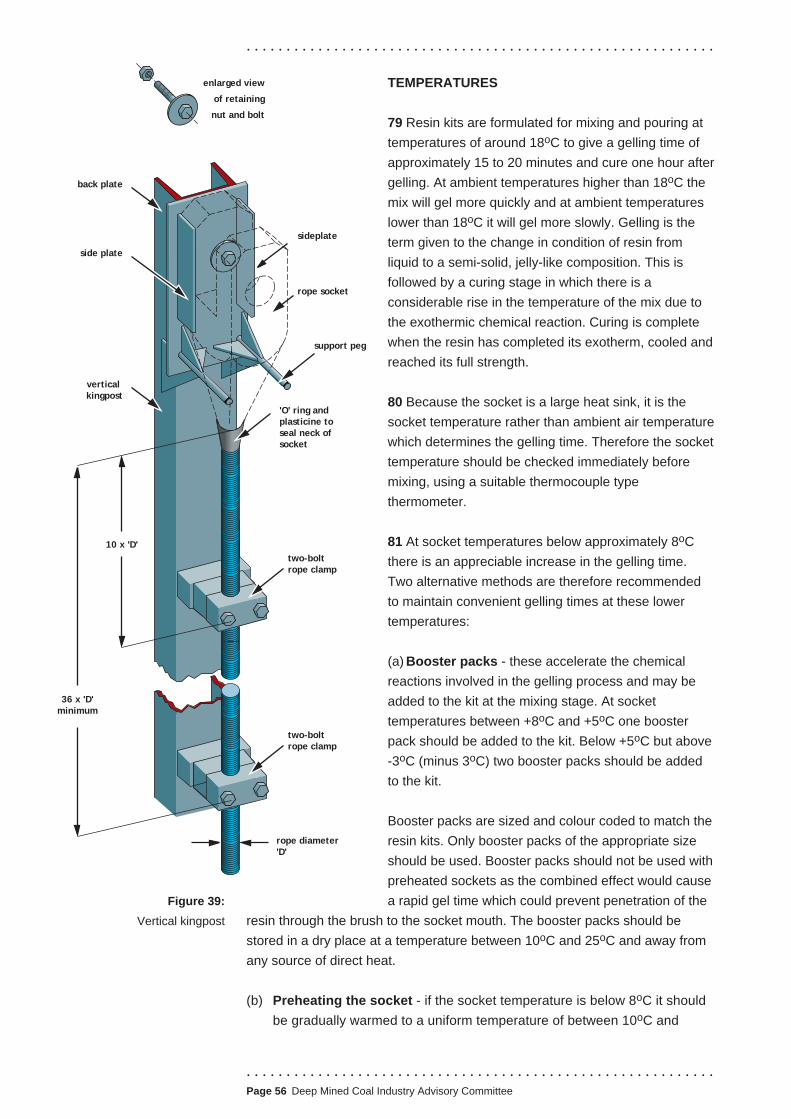
. . . . . . . . . . . . . . . . . . . . . . . . . . . . . . . . . . . . . . . . . . . . . . . . . . . . . . . . . . .
enlarged view TEMPERATURES of retaining
nut and bolt 79 Resin kits are formulated for mixing and pouring at
temperatures of around 18oC to give a gelling time of
approximately 15 to 20 minutes and cure one hour after
gelling. At ambient temperatures higher than 18oC the
mix will gel more quickly and at ambient temperatures
lower than 18oC it will gel more slowly. Gelling is the sideplate
back plate
'O' ring and
plasticine to
seal neck of
socket
vertical
kingpost
side plate
two-bolt
rope clamp
10 x 'D'
36 x 'D'
minimum
two-bolt
rope clamp
rope diameter
'D'
term given to the change in condition of resin from
liquid to a semi-solid, jelly-like composition. This is
followed by a curing stage in which there is arope socket
considerable rise in the temperature of the mix due to
the exothermic chemical reaction. Curing is complete
support peg when the resin has completed its exotherm, cooled and
reached its full strength.
80 Because the socket is a large heat sink, it is the
socket temperature rather than ambient air temperature
which determines the gelling time. Therefore the socket
temperature should be checked immediately before
mixing, using a suitable thermocouple type
thermometer.
81 At socket temperatures below approximately 8oC
there is an appreciable increase in the gelling time.
Two alternative methods are therefore recommended
to maintain convenient gelling times at these lower
temperatures:
(a) Booster packs - these accelerate the chemical
reactions involved in the gelling process and may be
added to the kit at the mixing stage. At socket
temperatures between +8oC and +5oC one booster
pack should be added to the kit. Below +5oC but above
-3oC (minus 3oC) two booster packs should be added
to the kit.
Booster packs are sized and colour coded to match the
resin kits. Only booster packs of the appropriate size
should be used. Booster packs should not be used with
preheated sockets as the combined effect would cause
Figure 39: a rapid gel time which could prevent penetration of the
Vertical kingpost resin through the brush to the socket mouth. The booster packs should be
stored in a dry place at a temperature between 10oC and 25oC and away from
any source of direct heat.
(b) Preheating the socket - if the socket temperature is below 8oC it should
be gradually warmed to a uniform temperature of between 10oC and
. . . . . . . . . . . . . . . . . . . . . . . . . . . . . . . . . . . . . . . . . . . . . . . . . . . . . . . . . . . Page 56 Deep Mined Coal Industry Advisory Committee

. . . . . . . . . . . . . . . . . . . . . . . . . . . . . . . . . . . . . . . . . . . . . . . . . . . . . . . . . . .
. . . . . . . . . . . . . . . . . . . . . . . . . . . . . . . . . . . . . . . . . . . . . . . . . . . . . . . . . . .
.Page 57 Deep Mined Coal Industry Advisory Committee
15oC, measured at the socket bore before the resin is poured in. This is
the only method that should be used if the socket temperature is below
-3oC (minus 3oC). It is usually possible to achieve temperatures in the
10oC to 15oC range by storing the socket in a suitably warm environment
for several hours before capping. The temperature should be maintained
during the brushing operation, but no part of the socket should be heated
above the upper (15oC) temperature limit, as this can accelerate the
gelling too much.
82 After removal from storage and prior to mixing, it is essential that the resin
kit is maintained within the storage temperature range of 10oC to 25oC. For
example, the kit should not be placed in direct sunlight, near hot radiators, or
left outside in cold weather.
MIXING
83 Those mixing the resin should inspect the powder before use; it should be
off-white and free flowing. If the powder is discoloured (especially brown) or
lumpy, it should not be used and returned to the manufacturer for investigation.
The liquid resin should be free flowing and pour easily from the can. An
identical spare kit should be available in case either the powder or liquid resin
quality is suspect.
84 Mix all of the liquid resin with all of the powder, gradually adding the
powder and stirring briskly until a uniform bluish-green colour is obtained.
The colour is an important indicator that the mixed kit conforms with the
manufacturer’s specification and can be used. If the mixed kit remains a pale
straw colour, the kit should not be used and returned to the manufacturer
for investigation.
85 Sufficient resin mix should be prepared to enable the socket to be
completely filled at one pouring. It is possible to combine various kit sizes to
achieve the required volume, eg 2700 cc = 1 x 1000 cc plus 1 x 1700 cc etc. In
such cases, all the liquid resin should be poured into the mixing vessel first,
followed by all the powder, so that the total mix can be prepared in one
operation. The 500 cc kit should only be used individually, as it is specially
formulated for smaller ropes and sockets.
86 It is essential that the mixing takes place as quickly as possible and that no
unmixed solids remain in the mixing vessel. Complete mixing normally takes
about two minutes. A suitable stirrer is included in each kit, but mechanical
mixing may be used for larger volumes, say 3400 cc and above. For
mechanical mixing, experience has shown that a simple triangular mixer made
from 10 mm diameter rod is suitable (Figure 40).
87 Where a booster pack is used, it should be added to the powder before
mixing with the liquid resin.
100 mm rod
100 mmtriangular mixer
Figure 40: Triangular mixer

. . . . . . . . . . . . . . . . . . . . . . . . . . . . . . . . . . . . . . . . . . . . . . . . . . . . . . . . . . .
POURING
88 Once the resin is mixed it should be poured immediately into the socket.
This will ensure good penetration through the brush and down to the socket
neck. It will also ensure that the gelling stage occurs in the socket and not in
the mixing vessel.
89 No more than two cappings should be poured from one mix.
90 The mixture should be poured at a fairly slow and steady rate in one
position, to avoid air entrapment, and continue until the socket is full.
Immediately after pouring the mixture in, the socket should be puddled for a few
seconds with a length of clean stiff wire to help free any entrapped air, and
confirm that the resin in the socket has not started to gel.
91 If the resin settles, the socket should be topped-up using the original mix.
Before topping-up, the mix should be re-stirred for a short period.
92 Any leakage of resin can be critical and must be stopped immediately,
otherwise it may result in cavities being formed near the root of the brush. Gelling
of the resin tends to start at the wider end of the socket, owing to the greater
amount of resin present and therefore slightly higher temperatures during the
exothermic reaction. If leakage is occurring at this time near the root of the brush,
it may not be accompanied by a drop in the level of resin at the wider end of the
socket and may be difficult to correct because of the gelling resin above it. Leaks
may occur not only from the neck of the socket but also from the served section
of rope below the capping. Always keep available some plasticine to seal any
leaks detected during pouring and in the early stages of gelling.
93 If there is not sufficient resin to fill the socket using the original mix then the
capping must be discarded and completely remade.
Curing 94 Movement of the rope or socket during gelling and curing can seriously
reduce the efficiency of the capping. The resin should therefore be allowed to
gel and cure before disturbing the rope and socket.
95 To determine whether or not curing is complete, a sharp implement, such
as a screwdriver blade, is drawn over the surface of the resin at the large end
of the cone. This should leave only a shallow light coloured scratch mark on the
surface. It is quite normal, particularly on small sockets, to have a very thin
tacky layer on the surface of the resin after curing. The scratch test can be
carried out through this layer.
96 The final colour after curing is a function of the peak exotherm temperature
reached during the cure; the hotter the cure the more sandy-brown it becomes,
and the cooler the cure the more bluish-green it remains. The resin will tend to go
sandy-brown in larger sockets and in the mixing vessel. In smaller sockets when
the mass of the socket compared with that of the resin is relatively large, the resin
. . . . . . . . . . . . . . . . . . . . . . . . . . . . . . . . . . . . . . . . . . . . . . . . . . . . . . . . . . . Page 58 Deep Mined Coal Industry Advisory Committee

. . . . . . . . . . . . . . . . . . . . . . . . . . . . . . . . . . . . . . . . . . . . . . . . . . . . . . . . . . .
does not reach high temperatures during exotherm, due to the heat sink effect of
the metal. The resin cone may therefore tend to remain a bluish-green colour.
97 Following a satisfactory scratch test, allow a minimum of one hour before
the service load is applied to the rope.
Inspection 98 After removing the seals and any collar of excess resin or plasticine around
the mouth of the socket, an experienced person should inspect the capping and
the serving adjacent to the socket, to ensure that it has been satisfactorily
carried out.
99 Checks should be carried out to confirm that:
(a) the socket and the rope axis are aligned;
(b) the annulus between the rope and the small end of the socket is even and
filled with resin;
(c) the socket is filled
with resin;collar left by
(d) the ends of the centering clamp following capping
brush wires protrude using white metal by a few millimetres
beyond the end of
the resin cone.
Marking 100 A well-defined paint paint markmark should be made
around the rope, about
12 mm wide and about 50 mm from the socket
(Figure 41). This will indicate any broken wire Figure 41: Marking
which might occur at the socket neck, as it
makes it easy to detect any movement of an individual wire.
Re-lubrication 101 The rope adjacent to the narrow end of the socket should be re-lubricated,
taking care to seal the neck of the socket. Any remaining servings and clamps
should also be removed and the rope lubricated in those areas.
Handling 102 If the socket moves inadvertently back along the rope during handling, it
should be moved clear of the resin cone. The cone can then be examined to
check that it is undamaged. If the cone is damaged or any wire misplaced, the
rope should be recapped.
103 When capping haulage ropes, to prevent the socket moving back along the
rope, a clamp should be fitted on the rope immediately adjacent to the socket.
The clamp should be removed at intervals to inspect the rope for corrosion and
fatigue damage.
. . . . . . . . . . . . . . . . . . . . . . . . . . . . . . . . . . . . . . . . . . . . . . . . . . . . . . . . . . .
.Page 59 Deep Mined Coal Industry Advisory Committee

Rope service requirements
Rope service requirements
Rope service requirements
Disposal of resin
residue
Other safety
precautions
Reporting
Application of service
loading
Resin kit sizes
. . . . . . . . . . . . . . . . . . . . . . . . . . . . . . . . . . . . . . . . . . . . . . . . . . . . . . . . . . .
104 Mixed materials should be allowed to cure and then be disposed of as
normal rubbish together with the used cans. The empty resin cans should not
be resealed.
105 Cured resin is not affected by oils or greases and is unlikely to be affected
by any chemical action likely to be encountered during service in a mine
environment. However, special care should be taken to ensure that substances
containing strong caustic or acid solutions, such as paint remover, do not come
into contact with the cured resin as these will act as a solvent and may reduce
the integrity of the capping.
106 Immediately following completion of the capping, information should be
provided on the sample form shown at Appendix 1.
107 When the service load is applied to the rope the resin cone will pull into the
socket (bed-in) by a few millimetres.
108 A schedule of the rope sizes covered by resin kits for various socket types
is shown in Tables 7 to 11 below:
Rope diameter One rope 16-24 mm 25-32 mm 33-40 mm 41-48 mm 49-53 mm 54-64 mm
Two ropes - - 25-30 mm 31-35 mm 36-40 mm 41-48 mm
Resin kit volume 500 cc 1000 cc 1700 cc 2700 cc
(ie1000 cc
+ 1700 cc)
3400 cc 5100 cc
(ie 1700 cc
+ 3400 cc)
Table 7: Resin kits for NCB Specification 465:196512 Sockets for winding, balance and
haulage purposes
Rope diameter One rope 21-44 mm 45-54 mm 55-67 mm 68-75 mm
Two ropes 21-32 mm 33-38 mm 39-48 mm 49-54 mm
Resin kit volume 1000 cc 1700 cc 2700 cc
(ie 1000 cc + 1700 cc)
3400 cc
Table 8: Resin kits for balance rope sockets to MECH/CIRC(81)8215
Rope diameter One rope 29-32 mm 33-38 mm 39-48 mm 49-51 mm
Two ropes - - 29-35 mm 36-38 mm
Resin kit volume 1000 cc 1700 cc 2700 cc
(ie 1000 cc + 1700 cc)
3400 cc
Table 9: Resin kits for guide rope suspension glands
. . . . . . . . . . . . . . . . . . . . . . . . . . . . . . . . . . . . . . . . . . . . . . . . . . . . . . . . . . . Page 60 Deep Mined Coal Industry Advisory Committee
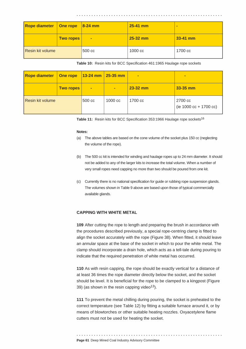
Rope service requirements
Rope service requirements
. . . . . . . . . . . . . . . . . . . . . . . . . . . . . . . . . . . . . . . . . . . . . . . . . . . . . . . . . . .
Rope diameter One rope 8-24 mm 25-41 mm -
Two ropes - 25-32 mm 33-41 mm
Resin kit volume 500 cc 1000 cc 1700 cc
Table 10: Resin kits for BCC Specification 461:1965 Haulage rope sockets
Rope diameter One rope 13-24 mm 25-35 mm - -
Two ropes - - 23-32 mm 33-35 mm
Resin kit volume 500 cc 1000 cc 1700 cc 2700 cc
(ie 1000 cc + 1700 cc)
Table 11: Resin kits for BCC Specification 353:1966 Haulage rope sockets16
Notes:
(a) The above tables are based on the cone volume of the socket plus 150 cc (neglecting
the volume of the rope).
(b) The 500 cc kit is intended for winding and haulage ropes up to 24 mm diameter. It should
not be added to any of the larger kits to increase the total volume. When a number of
very small ropes need capping no more than two should be poured from one kit.
(c) Currently there is no national specification for guide or rubbing rope suspension glands.
The volumes shown in Table 9 above are based upon those of typical commercially
available glands.
CAPPING WITH WHITE METAL
109 After cutting the rope to length and preparing the brush in accordance with
the procedures described previously, a special rope-centring clamp is fitted to
align the socket accurately with the rope (Figure 38). When fitted, it should leave
an annular space at the base of the socket in which to pour the white metal. The
clamp should incorporate a drain hole, which acts as a tell-tale during pouring to
indicate that the required penetration of white metal has occurred.
110 As with resin capping, the rope should be exactly vertical for a distance of
at least 36 times the rope diameter directly below the socket, and the socket
should be level. It is beneficial for the rope to be clamped to a kingpost (Figure
39) (as shown in the resin capping video13).
111 To prevent the metal chilling during pouring, the socket is preheated to the
correct temperature (see Table 12) by fitting a suitable furnace around it, or by
means of blowtorches or other suitable heating nozzles. Oxyacetylene flame
cutters must not be used for heating the socket.
. . . . . . . . . . . . . . . . . . . . . . . . . . . . . . . . . . . . . . . . . . . . . . . . . . . . . . . . . . .
.Page 61 Deep Mined Coal Industry Advisory Committee

. . . . . . . . . . . . . . . . . . . . . . . . . . . . . . . . . . . . . . . . . . . . . . . . . . . . . . . . . . .
Socket material
Mild steel
1.5% manganese steel and other approved steels
to BS 2772-2:198917
Preheating temperature
100oC
100oC-205oC
Table 12: Preheating temperatures for sockets
112 Heating steel sockets to the upper end of the temperature range will
lead to better penetration of the white metal into the socket. When using
heating nozzles, operators should take care to apply the heat evenly to all
parts of the socket. Under no circumstances must flame be allowed to play
on any part of the rope. The socket temperature can be readily checked by
applying suitable thermocrayons or a contact type pyrometer to various parts
of the socket.
113 While the preheating operation is being carried out on the socket, the white
metal (to BS 643:1970 - White metal ingots for capping steel wire ropes18)
should be prepared and heated to the correct pouring temperature of
350oC±14oC. A predetermined weight of white metal in excess of that required
to fill the socket should be broken up, placed in a clean pot and heated in a
furnace until molten; flame should not be allowed to play on the metal itself.
New ingots must be used for winding rope capping.
114 When using ropes with synthetic fibre cores, operators will need to take
extreme care when capping with white metal, as polypropylene, for example,
melts at about 130oC. Therefore, the part of the core close to the capping might
be adversely affected by heat during the capping process.
115 The wires within the socket should be treated with a non-acid flux or finely
powdered rosin, which must be dusted among all the wires within the heated
socket immediately before pouring the white metal.
116 When the molten metal reaches a temperature slightly in excess of the
pouring temperature, it is stirred thoroughly right to the bottom of the pot, and
any dross skimmed from the surface. Ensure that the stirring and skimming
implements are clean and dry. The pot should have a vertical baffle close to the
pouring lip and extending to within 25 mm of the bottom. This allows only clean
metal to be poured.
117 Once the metal has been stirred and skimmed, and is at the correct
pouring temperature, it is poured into the socket in a continuous stream until it
reaches the top of the basket. The pouring should be done slightly off-centre to
allow for venting and for any gas to escape. At the start of the operation white
metal should run from the tell-tale hole in the centring clamp. The metal should
be allowed to run for two or three seconds before the hole is plugged using a
suitable stopper.
. . . . . . . . . . . . . . . . . . . . . . . . . . . . . . . . . . . . . . . . . . . . . . . . . . . . . . . . . . . Page 62 Deep Mined Coal Industry Advisory Committee
. . . . . . . . . . . . . . . . . . . . . . . . . . . . . . . . . . . . . . . . . . . . . . . . . . . . . . . . . . .
Dismantling the
clamps and servings
Possible faults in
procedure
118 If a depression or ‘pipe’ occurs in the centre of the white metal during the
early stages of cooling it should be topped up with a small amount of white
metal. When the basket is full, the socket should be left to cool naturally and
undisturbed for at least one hour.
119 A report covering the above details should be prepared for each completed
white metal capping in a similar format to that for resin cappings as shown at
Appendix 1.
120 After the completed socket has cooled, the rope-centring clamp and two-
bolt clamps are removed and the socket neck is examined to make sure that
the white metal has penetrated around the whole of the rope circumference
and that the socket is full. If the remaining metal in the pot after pouring,
together with any spillage, is weighed, the weight of the metal in the capping
can be determined.
121 The socket should be allowed to cool to air temperature before use.
If there is insufficient time for natural cooling, a stream of cold air may be
directed onto the socket, but this should only be done after the white metal has
completely solidified. In no circumstances should the socket be immersed in
water for cooling.
122 All the servings should now be removed, the long serving up to the point
where it enters the mouth of the socket. This is to facilitate subsequent
examinations of the rope near the socket mouth.
123 As for resin cappings, a well-defined paint mark should be made around the
rope about 12 mm wide positioned approximately 50 mm from the socket (Figure
41), to provide for easy identification of any broken wire at the socket neck.
124 When the capping has reached air temperature the length of rope next to
the socket must be re-lubricated. The capping is then ready for use.
125 The white metal used must be of the correct composition (BS 643:197018),
and heated to the correct temperature (350oC±14oC), otherwise it may fail to
penetrate to the narrow end of the conical part of the socket and, therefore, to
the narrow end of the brush of separated wires. Conversely, the temperature of
the white metal should not exceed that specified, otherwise the heat may
adversely affect the wires of the brush. An open socket (one with two lugs
rather than a bowed end) facilitates the pouring of the white metal.
126 The socket must be of the correct size; for winding ropes it must conform
to NCB Specification 465/1965.12 If the socket is too short, the length of each
wire embedded in the white metal will be insufficient to ensure that the wire is
securely gripped at loads up to its breaking strength. A length of embedded
wire equal to about 40 times its diameter will ensure proper grip and leave a
margin for safety, provided that the wire has been properly cleaned. On the
other hand, the socket must not be too long otherwise the taper of the conical
. . . . . . . . . . . . . . . . . . . . . . . . . . . . . . . . . . . . . . . . . . . . . . . . . . . . . . . . . . .
.Page 63 Deep Mined Coal Industry Advisory Committee

. . . . . . . . . . . . . . . . . . . . . . . . . . . . . . . . . . . . . . . . . . . . . . . . . . . . . . . . . . .
. . . . . . . . . . . . . . . . . . . . . . . . . . . . . . . . . . . . . . . . . . . . . . . . . . . . . . . . . . .Page 64 Deep Mined Coal Industry Advisory Committee
part will not be steep enough or wide enough to allow the
molten white metal to reach the narrow end of the socket
before solidifying. The taper should be 1 in 7 or steeper (8o
or more).
127 If the wires at the narrow end of the socket are loose and
unsupported, they will bend and twist as the rope moves,
increasing the likelihood of fatigue failure (Figure 42). In order
to ensure that the wires at the narrow end of the brush are
properly embedded in white metal, the procedure stipulates
that the narrow end of the brush should not lie right at the
narrow end of the conical part of the socket, but should lie
further inside at a wider part of the socket. Therefore, when
fitting sockets to NCB Specification 465/1965,12
a length of seized rope about twice the rope diameter should
lie within the socket mouth.
RECOVERY OF A SOCKET
128 The white metal cone should be removed from the socket by pressing
out. Should this prove difficult the socket may be warmed; provided that the
critical temperature for preheating, given in Table 12, is not exceeded.
Examination of the extracted cone will provide useful information on the
quality of capping procedures.
WEDGE CAPPING
129 Wedge cappings work on the principle of gripping the
rope between interlocking tapered wedges (with grooves
to suit the rope diameter), which are enclosed in limbs
encircled by heavy bands (Figure 43a). After initial
bedding down, the rope should not move in the wedges
and, because of their interlocking action, the wedges
cannot move independently of each other. The wedges
and the rope must, however, be able to move as a unit, so
that if the load on the capping is sufficient to cause
movement of this unit, the force on the wedges will be
increased and consequently the grip exerted upon the
rope will be greater. A safety block is fitted to act as a rope
movement indicator and to assist movement of the
wedges should this become necessary.
130 The capping can be used with stranded or locked
coil ropes. While the following guidance relates to its use
on a locked coil rope, it applies equally to its use on a
stranded rope.
Figure 42: Fractured wires
3
2
1
1
4
Figure 43a:
Wedge capping

Serving and clamping
Cutting
Fitting the safety block
. . . . . . . . . . . . . . . . . . . . . . . . . . . . . . . . . . . . . . . . . . . . . . . . . . . . . . . . . . .
131 Capping wedges are stamped with the rope type and size for which they
are designed, and also with the capping identification number. Wedges should
be fitted only to a capping having the same identification number. Check that all
component parts, ie limbs, bands and wedges, bear the same capping number
(Figure 43a). Cappings should NEVER be used with a size or type of rope
different from that stamped upon the wedges. The number of bands will vary
with the design and manufacturers of the capping.
132 Under no circumstances should liners be used in the grooves or at the
backs of the wedges.
133 Check the length of rope to be gripped by the wedges for uniformity of
diameter and compliance with the capping rope groove tolerances.
134 The rope must be securely served and clamped on both sides of the
proposed cutting position in the same way as for resin and white metal capping;
the length CD (Figure 23a) for locked coil ropes should be at least equal to 20 x
rope diameter (d) plus the length of the safety block.
135 Cut the rope in the same way as for resin and white metal capping.
136 Thread the safety block, which should be clean and dry, over the rope end
so that the larger end of the conical bore is towards the rope end. Fit a
temporary clamp over the serving so that its top edge is the length of the safety
block less one-half the rope diameter from the rope end and remove the
serving wire at the rope end down to the top of this clamp. The procedure is
now similar to that for making a resin or white metal capping:
(a) Separate the wires at the rope end to form a small
brush, cutting out the fibre core, if present, close to
the serving. Avoid undue bending of the wires over
the edge of the clamp (Figure 43b).
(b) Thoroughly clean all the wires in the brush with a
water-soluble degreasing fluid, with the rope brush
pointing downwards, so that no degreasing fluid
enters the unopened part of the rope. Remove the
temporary clamp close to the brush.
(c) Pull the safety block into position over the rope brush
so that a length of serving equal to one half the rope
diameter is projecting into the bore of the block. The
wire ends should be flush with the top of the block.
(d) Clamp the rope, with the safety block in place,
vertically with the large end of the block uppermost. Figure 43b: Fitting
Ensure that the axes of the rope and safety block are the safety block
in line for at least 36 x rope diameter (d).
. . . . . . . . . . . . . . . . . . . . . . . . . . . . . . . . . . . . . . . . . . . . . . . . . . . . . . . . . . .
.Page 65 Deep Mined Coal Industry Advisory Committee
. . . . . . . . . . . . . . . . . . . . . . . . . . . . . . . . . . . . . . . . . . . . . . . . . . . . . . . . . . .
(e) Seal the bottom of the safety block with a tight serving of heat resistant
yarn, to prevent the escape of molten white metal.
(f) Heat the outside of the block with a blowtorch, gradually and evenly all
round the outer faces. Heating of the block is essential to ensure the free
flow of molten metal, undue heating may impair the strength of the rope
wires. Avoid undue local heating and particularly avoid heating the rope
outside the block. Monitor the temperature of the block with thermal crayons
or any other suitable method. When the block is at the correct temperature
(see Table 12), before pouring the white metal, a non-acid flux or finely
powdered rosin should be dusted among the wires in the core of the block.
(g) Fill the block with molten, clean white metal, poured at a temperature of
350oC±14oC. Pouring should be continuous, uniform and slightly off-centre
until the white metal completely fills the block. If the surface of the white
metal sinks in the centre, pour in a little more white metal.
(h) The white metal used should have been previously melted from new ingots
of the composition laid down in BS 643: 1970.18 The pouring pot should be
of sufficient capacity to hold the full amount of white metal to fill the bore of
the safety block. The pot should have a minimum capacity level mark for the
quantity of molten white metal required for the block, and should incorporate
a baffle plate to ensure that only clean, bright fluid metal is poured into the
prepared, heated safety block. Using a suitable thermometer, confirm the
temperature of the white metal immediately before pouring.
(i) Leave the rope and block undisturbed and allow it to cool gradually until
the white metal has set and the block has reached air temperature.
(j) Remove the heat resistant yarn and the serving from below the safety
block and check that the white metal has fully penetrated the block.
(k) Check the length of rope to be gripped by the wedges for uniformity of
diameter and compliance with the capping rope groove tolerances.
Fitting the capping 137 Prior to assembly, remove any protective paint, grease or backing strips from
capping limbs and wedges. Using only emery cloth, remove any traces of rust
which may have accumulated on the wedge backs and grooves, and also on the
inside of the limbs over the area on which the wedges operate. Remove any
burrs or damage on wedges and limb sections that have occurred in handling,
storage or transit, particularly the areas over which the wedges operate.
138 Assemble the capping as follows:
(a) Thread the capping bands onto the rope in order of their numbers (always
the band of smallest aperture first - usually the one with the highest
number). Make sure that the taper on the inside of the bands is in the
. . . . . . . . . . . . . . . . . . . . . . . . . . . . . . . . . . . . . . . . . . . . . . . . . . . . . . . . . . . Page 66 Deep Mined Coal Industry Advisory Committee
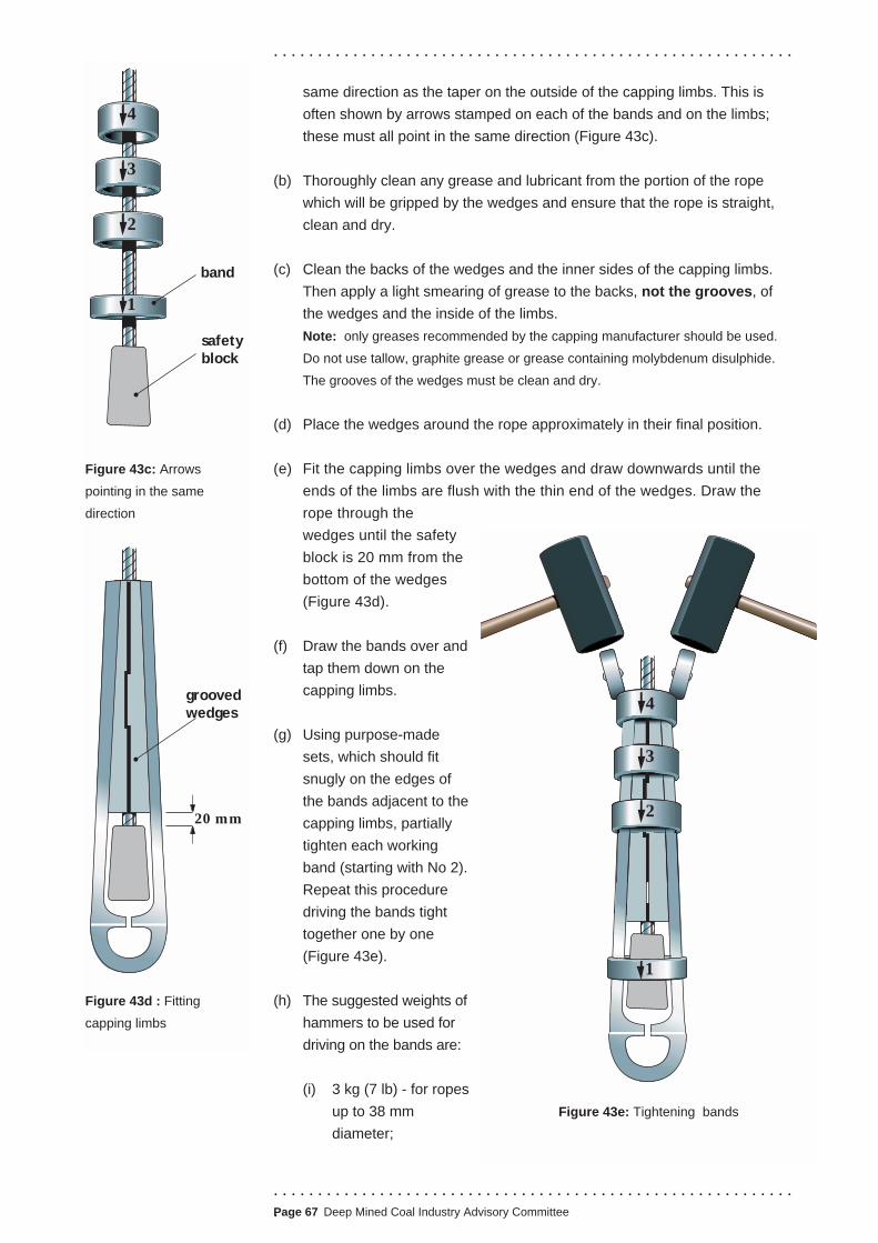
. . . . . . . . . . . . . . . . . . . . . . . . . . . . . . . . . . . . . . . . . . . . . . . . . . . . . . . . . . .
.Page 67 Deep Mined Coal Industry Advisory Committee
same direction as the taper on the outside of the capping limbs. This is
often shown by arrows stamped on each of the bands and on the limbs;
these must all point in the same direction (Figure 43c).
(b) Thoroughly clean any grease and lubricant from the portion of the rope
which will be gripped by the wedges and ensure that the rope is straight,
clean and dry.
(c) Clean the backs of the wedges and the inner sides of the capping limbs.
Then apply a light smearing of grease to the backs, not the grooves, of
the wedges and the inside of the limbs.
Note: only greases recommended by the capping manufacturer should be used.
Do not use tallow, graphite grease or grease containing molybdenum disulphide.
The grooves of the wedges must be clean and dry.
(d) Place the wedges around the rope approximately in their final position.
(e) Fit the capping limbs over the wedges and draw downwards until the
ends of the limbs are flush with the thin end of the wedges. Draw the
rope through the
wedges until the safety
block is 20 mm from the
bottom of the wedges
(Figure 43d).
(f) Draw the bands over and
tap them down on the
capping limbs.
(g) Using purpose-made
sets, which should fit
snugly on the edges of
the bands adjacent to the
capping limbs, partially
tighten each working
band (starting with No 2).
Repeat this procedure
driving the bands tight
together one by one
(Figure 43e).
(h) The suggested weights of
hammers to be used for
driving on the bands are:
(i) 3 kg (7 lb) - for ropes
up to 38 mm
diameter;
4
3
2
1
band
safetyblock
Figure 43c: Arrows
pointing in the same
direction
groovedwedges
20 mm
Figure 43d : Fitting
capping limbs
4
3
2
1
Figure 43e: Tightening bands
. . . . . . . . . . . . . . . . . . . . . . . . . . . . . . . . . . . . . . . . . . . . . . . . . . . . . . . . . . .
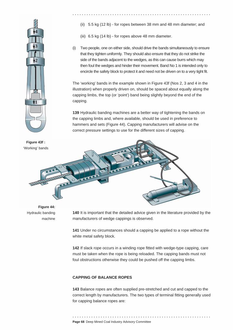
. . . . . . . . . . . . . . . . . . . . . . . . . . . . . . . . . . . . . . . . . . . . . . . . . . . . . . . . . . .
. . . . . . . . . . . . . . . . . . . . . . . . . . . . . . . . . . . . . . . . . . . . . . . . . . . . . . . . . . .Page 68 Deep Mined Coal Industry Advisory Committee
(ii) 5.5 kg (12 lb) - for ropes between 38 mm and 48 mm diameter; and
(iii) 6.5 kg (14 lb) - for ropes above 48 mm diameter.
(i) Two people, one on either side, should drive the bands simultaneously to ensure
that they tighten uniformly. They should also ensure that they do not strike the
side of the bands adjacent to the wedges, as this can cause burrs which may
then foul the wedges and hinder their movement. Band No 1 is intended only to
encircle the safety block to protect it and need not be driven on to a very tight fit.
The ‘working’ bands in the example shown in Figure 43f (Nos 2, 3 and 4 in the
illustration) when properly driven on, should be spaced about equally along the
capping limbs, the top (or ‘point’) band being slightly beyond the end of the
capping.
139 Hydraulic banding machines are a better way of tightening the bands on
the capping limbs and, where available, should be used in preference to
hammers and sets (Figure 44). Capping manufacturers will advise on the
correct pressure settings to use for the different sizes of capping.
140 It is important that the detailed advice given in the literature provided by the
manufacturers of wedge cappings is observed.
141 Under no circumstances should a capping be applied to a rope without the
white metal safety block.
142 If slack rope occurs in a winding rope fitted with wedge-type capping, care
must be taken when the rope is being reloaded. The capping bands must not
foul obstructions otherwise they could be pushed off the capping limbs.
CAPPING OF BALANCE ROPES
143 Balance ropes are often supplied pre-stretched and cut and capped to the
correct length by manufacturers. The two types of terminal fitting generally used
for capping balance ropes are:
Figure 44:
Hydraulic banding
machine
3
2
1
4
Figure 43f :
‘Working’ bands

. . . . . . . . . . . . . . . . . . . . . . . . . . . . . . . . . . . . . . . . . . . . . . . . . . . . . . . . . . .
.Page 69 Deep Mined Coal Industry Advisory Committee
■ resin or white metal capping for round
ropes (Figure 21);
■ thimbles and clamps for flat ropes
(Figure 45).
144 The method of fitting resin and white
metal cappings to balance ropes is the same
as that used for winding ropes and is
described earlier in this guidance. Following
capping, a report should be made in
accordance with Appendix 1.
145 Balance ropes may be attached to the
conveyance by means of a specially formed
pear-shaped thimble (or bobbin). The free
end of the rope is bent around the thimble,
then laid back along the working rope and
adequately secured by a number of two or
four-bolt clamps.
146 The whole assembly is then suspended
beneath the conveyance by purpose-
designed suspension links or solid stirrup
arrangements. The thimble is retained within
the suspension links, or stirrups by a
captivated retaining pin. Figure 45 shows the
arrangement for a flat balance rope.
CAPPING OF GUIDE AND RUBBING
ROPES
147 The principal method of suspending
guide ropes is by means of a resin or white
metal capping or a wedge-type suspension
gland in the headframe. White metal and
resin cappings should have a taper length of
eight times the rope diameter and an included taper of 1 in 6. A typical
suspension gland for resin and white metal capping is shown at Figure 46a.
148 Guide rope and rubbing rope cappings or suspension glands are normally
above the supporting structure where there is usually adequate space for lifting,
rotating and recapping the ropes.
149 The procedure is the same as for winding ropes as described earlier in this
guidance. This type of capping is being progressively replaced by resin capping
in UK mines.
Resin or white metal
cappings
Thimble and clamp
terminal fastenings for
flat balance ropes
White metal capping
suspension links
or stirrup
captivated
retaining pin
thimble or
bobbin
two or four-bolt
clamps, with
chamfered inside
edges
Figure 45: Flat
balance rope
. . . . . . . . . . . . . . . . . . . . . . . . . . . . . . . . . . . . . . . . . . . . . . . . . . . . . . . . . . .

. . . . . . . . . . . . . . . . . . . . . . . . . . . . . . . . . . . . . . . . . . . . . . . . . . . . . . . . . . .
Figure 46a:
Suspension gland for resin
and white metal
150 For the reasons described earlier in this guidance, resin cappings are
recommended in preference to white metal, and the procedure is the same as
previously described for winding ropes. However, on large diameter guide
ropes, the resin may crack during the curing stage if the outer wire rods are
allowed to press heavily against the inner wall of the socket. It is probably
caused by a combination of the stresses in the outer rods, that are created by
them being restrained by the wall of the socket, and the force induced by the
resin as it contracts inwards away from the wall of the socket.
151 To avoid this situation, space out the wire rods as evenly as possible within
the socket, allowing none of them to touch the socket wall at the wide end of
the socket. Try to maintain a space of one wire rod diameter between the bore
and any wire rod at the wide end of the socket.
152 As with other ropes, once the rope termination is complete, a report should
be made in accordance with Appendix 1.
Resin capping
. . . . . . . . . . . . . . . . . . . . . . . . . . . . . . . . . . . . . . . . . . . . . . . . . . . . . . . . . . . Page 70 Deep Mined Coal Industry Advisory Committee

. . . . . . . . . . . . . . . . . . . . . . . . . . . . . . . . . . . . . . . . . . . . . . . . . . . . . . . . . . .
Wedge type 153 This type of guide rope suspension (Figure 46b) has generally been
suspension glands superseded by resin type capping, however, the procedures explained are
applicable to manoeuvring glands which continue to be used for shaft work.
Wedge suspension glands should
be fitted in the following manner and
before assembling the gland, the
following points should be checked:
(a) Measure accurately the
diameter of the rope at the point
of suspension to determine the
maximum and minimum
diameters. No gland should be
fitted to a rope which differs in
diameter by more than ± 0.75
mm of the diameter stamped on
the wedges.
(b) Check that the safe working load
(SWL) stamped on the gland is
not less than the static load that
will be imposed on the rope.
(c) Check that the assembly
numbers stamped on the
wedges and the gland case are
the same. Gland cases should
be fitted only with wedges
bearing the same number.
Assembling the gland 154 Wedge suspension glands
should be assembled in the
following manner:
(a) Clean the gland case and
wedges to remove any
protective grease or paint.
Using ‘emery cloth’ only,
remove any traces of rust from
the backs of the wedges, the
grooves and the recess in the
gland case. Remove any burrs
from the wedges or gland case
recess. If left, they may
interfere with the free
movement of the wedges.
Figure 46b: Suspension gland
. . . . . . . . . . . . . . . . . . . . . . . . . . . . . . . . . . . . . . . . . . . . . . . . . . . . . . . . . . .
.Page 71 Deep Mined Coal Industry Advisory Committee

. . . . . . . . . . . . . . . . . . . . . . . . . . . . . . . . . . . . . . . . . . . . . . . . . . . . . . . . . . .
(b) Thoroughly clean the grease from that part of the rope to which the gland
is to be attached, and ensure that this part of the rope is straight, clean
and dry.
(c) Bolt the gland case round the rope at the required position. With all types
of suspension gland the joint of the casing must be supported across the
joists ie the joint should be at right angles to the girders (Figure 46b).
(d) Grease the backs, not the grooves, of the wedges before placing them
in position around the rope. Also, lightly grease the recess in the gland
case into which the wedges fit, using only suitable greases. Do not use
tallow, graphite grease or any grease containing molybdenum disulphide.
(e) Insert the wedges and drive them firmly in to ensure that they are down on
the rope and starting to grip and that they are level and tight. To prevent
burring, use a suitably shaped brass or copper set in conjunction with the
hammer, taking care not to damage the rope when driving in the wedges.
When fitted correctly, the tops of the wedges should be approximately 11/ 2
to 2 times the rope diameter above the top of the gland case.
(f) Then fit correctly sized two-bolt clamps (not four-bolt clamps, which are
less efficient). The clamps should be bolted onto the rope in contact with
and at 90o to one another, and with the bottom clamp in contact with the
tops of the wedges. The clamp bolts, after cleaning and lightly greasing,
should be tightened to the torque shown in Table 13.
Rope diameter Bolt size Tightening torque Load carrying capacity per clamp
16-24 mm M20 150 Nm (110 lbf ft) 1 tonne
45-64 mm M30 450 Nm (330 lbf ft) 2 tonnes
Table 13: Tightening torques for two-bolt clamp bolts
155 The required number of two bolt clamps is derived from the table and is
determined by the total load to be manoeuvred or supported. In addition to the
required number of contact clamps a marker or tell-tale clamp should be fitted
approximately 25 mm above the top contact clamp. This space will act as an
indicator should any rope slip occur.
156 Make sure the suspended load (ie weight and rope) is properly secure, that
the slack rope is properly secure, that there is slack rope immediately beneath
the gland, and that there are suitable arrangements to control the slack rope
before attempting to release it. Then:
(a) Remove all of the two-bolt clamps.
(b) Raise the gland approximately 75 mm above the supporting structure.
Dismantling a gland
. . . . . . . . . . . . . . . . . . . . . . . . . . . . . . . . . . . . . . . . . . . . . . . . . . . . . . . . . . . Page 72 Deep Mined Coal Industry Advisory Committee

. . . . . . . . . . . . . . . . . . . . . . . . . . . . . . . . . . . . . . . . . . . . . . . . . . . . . . . . . . .
(c) Loosen the gland case bolts.
(d) Strike the gland case downwards with a sharp blow, avoiding the wedges
or rope, to release the wedges in the gland case.
(e) Remove the wedges.
(f) Remove the bolts from the gland case, split the case and set it aside. If the
gland is to be stored all parts should be thoroughly protected with a rust
preventing grease.
157 It is important that the detailed advice given in the literature provided by the
manufacturers of wedge capping is observed.
. . . . . . . . . . . . . . . . . . . . . . . . . . . . . . . . . . . . . . . . . . . . . . . . . . . . . . . . . . .
.Page 73 Deep Mined Coal Industry Advisory Committee

Introduction
. . . . . . . . . . . . . . . . . . . . . . . . . . . . . . . . . . . . . . . . . . . . . . . . . . . . . . . . . . .
TECHNICAL ANNEX 4 - MAINTENANCE PROCEDURES, DETERIORATION
AND DISCARD CRITERIA FOR SHAFT ROPES
MAINTENANCE PROCEDURES
1 All shaft ropes need careful maintenance to maximise their working life.
This part of the Technical Annex provides guidance on the care and lubrication
of shaft ropes, but mines will also need to refer to the appropriate
manufacturer’s instructions provided with the specific rope types.
2 There is a need to identify any lengths of rope where there is localised
drying effect on the rope lubricant. This may occur in specific areas of the rope
that are in vulnerable places, for example, to winding and balance ropes when,
conveyances are in their normally parked positions, from shaft heaters,
opposite fan drifts or shaft insets, shaft sumps, etc.
3 Balance ropes should be kept well lubricated, since moisture will otherwise
penetrate the loop in the lowest part of the rope in the sump, causing internal
corrosion. Water and debris levels in the sump must be kept below the bottom
of the loop.
4 Both guide and rubbing ropes may deteriorate in fatigue where they leave
the headframe capping or fixings. To prevent this, the position of the capping or
fixing should be moved along the rope from time to time. It is better to lift the
rope rather than to lower it, to get rid of any fatigued part near the top of the
rope. Recommended good practice is to lift the rope through a distance of at
least 1.5 times the length of the headframe capping at not more than five yearly
intervals. The rope should also be turned through 90o during the lifting and
recapping operation, to help spread any effects of localised wear. Further
advice on this subject can also be found in paragraphs 202 and 203 of the
ACOP to the 1993 Regulations.3
5 Sump tension weights (or cheese weights) should be inspected regularly to
check that corrosion has not weakened the centre rod to an extent that might
lead it to fail, or cause it to bend due to a build-up of rust between the cheese
weights.
6 Tension springs in the sump should also be inspected regularly to confirm
that the springs are effectively applying the required tension to the ropes. In
deep downcast shafts, seasonal temperature changes may require that the
springs be adjusted to maintain the required rope tension.
7 Routine inspections should check that weights or springs are not being
fouled by accumulated spillage. Similarly, water should not be allowed to rise
around the weights since buoyancy effects will reduce the rope tension.
. . . . . . . . . . . . . . . . . . . . . . . . . . . . . . . . . . . . . . . . . . . . . . . . . . . . . . . . . . . Page 74 Deep Mined Coal Industry Advisory Committee

. . . . . . . . . . . . . . . . . . . . . . . . . . . . . . . . . . . . . . . . . . . . . . . . . . . . . . . . . . .
ROPE LUBRICATION
8 The purpose of wire rope lubrication is to allow the wires within the rope to
move freely against one another, reducing friction and internal wear and
improving the distribution of load. Secondly, it protects both internal and
external surfaces of the wires from corrosion.
9 External lubricant reduces friction and external wear between the rope and
any drum or pulley over which it passes; and it can also help to reduce internal
wear by restricting penetration of dirt and grit which could otherwise cause
increased abrasion. In certain conditions, however, too liberal use of too sticky
an external lubricant will attract grit and so reduce rope life.
10 The essential properties of a wire rope lubricant are:
■ it must be tough enough to resist abrasion but sufficiently plastic to remain
intact as the rope flexes in service;
■ it must adhere firmly to the wires and be viscous enough to resist
gravitational forces where ropes hang vertically, and centrifugal forces
where ropes pass quickly around drums, sheaves or pulleys;
■ it must be non-corrosive and stable over the range of temperatures and
environmental conditions likely to be encountered. Under no circumstances
should it give rise to any by-products which would attack the metal strands;
■ it must be water-repellent to protect internal and external surfaces from
corrosion;
■ it must not deteriorate with age, exposure or temperature changes, eg by
hardening or cracking; and
■ a lubricant (dressing) applied externally during service should have good
penetration to compensate, as far as possible, for any loss of the
manufacturer’s internal lubricant. It must also be fully compatible with the
lubricant used in manufacture.
Lubrication of ropes 11 Because it is difficult to lubricate fully the internal part of a rope once it is
during manufacture made up, ropes are thoroughly lubricated at the manufacturing stage. The
majority of lubricants now used for this fall into two main classes:
■ petroleum-based compounds;
■ bitumen in mineral oil compounds.
12 Chemicals are added to the basic lubricant to improve the performance.
These additives include anticorrosion, anti-oxidation, water-repellent, anti-fret
agents, etc. Except in certain cases, the lubricant is applied during all stages of
. . . . . . . . . . . . . . . . . . . . . . . . . . . . . . . . . . . . . . . . . . . . . . . . . . . . . . . . . . .
.Page 75 Deep Mined Coal Industry Advisory Committee

. . . . . . . . . . . . . . . . . . . . . . . . . . . . . . . . . . . . . . . . . . . . . . . . . . . . . . . . . . .
manufacture. It is sometimes applied cold but more generally heated, according
to its viscosity, to obtain the optimum condition for application.
13 The completed rope may be passed through a final bath of lubricant. For
locked coil friction-winding ropes, specially developed bitumen-based lubricants
may be used. General practice is to heavily lubricate the inner layers of the
rope with a bitumen-in-oil compound, laying up the outer one or two layers in a
virtually dry condition. In service the lubricant spreads to the outer layers but
should still be contained within the rope, avoiding contamination of the drive
drum linings and, hence, rope slip.
14 Lubricants known as batching fluids are needed during the spinning of
natural fibre cores to prevent the fibres from breaking. To avoid internal
corrosion of the rope, these lubricants must be free from acids and water.
The core fibres themselves must be free from acids and salt and should contain
only the combined water necessary to prevent brittleness. BS 525:199119 gives
the requirements for such cores. Before incorporation into a rope, a fibre core
may be impregnated with further lubricant.
Lubrication and 15 If a rope is to remain in good condition it is important to re-lubricate it at
cleaning during intervals during service. The oil or grease (the rope ‘dressing’) used should be
service one specially designed for ropes, and should be free from all harmful substances
such as acids. It should be a mineral oil, as animal and vegetable oils tend to
break down and produce acids. Rope manufacturers and oil companies will
advise on suitable lubricants, including the additives to improve the properties.
16 The kind of dressing used and the frequency of application varies with the
type of rope and its usage, but there are certain general principles to be
followed:
■ Whenever practical apply the dressing as soon as the rope is put to work.
■ Reapply the dressing at regular intervals, normally before the rope shows
any signs of corrosion or dryness.
■ Periodically clean existing lubricant from the rope before relubricating,
particularly in dirty or dusty conditions (eg skip winding shafts).
■ If loose corrosion products are present on the rope surface, remove them
before applying fresh dressing.
■ The dressing and method of application should be such that a thin, even
adherent coating covers all the surface of the rope.
Drum-winder ropes 17 Drum-winder ropes should be re-lubricated at regular intervals; this should
be at least once a week for busy ropes in wet shafts. There are lubricants that
contain additives with anticorrosion, tackiness, water-repellent and, in some
cases, de-watering properties, that will be suitable in these circumstances.
. . . . . . . . . . . . . . . . . . . . . . . . . . . . . . . . . . . . . . . . . . . . . . . . . . . . . . . . . . . Page 76 Deep Mined Coal Industry Advisory Committee

. . . . . . . . . . . . . . . . . . . . . . . . . . . . . . . . . . . . . . . . . . . . . . . . . . . . . . . . . . .
. . . . . . . . . . . . . . . . . . . . . . . . . . . . . . . . . . . . . . . . . . . . . . . . . . . . . . . . . . .
.Page 77 Deep Mined Coal Industry Advisory Committee
18 The de-watering additives in bitumen-based dressing emulsify with the
water present on the rope and ensure that oil is kept in close contact with the
surfaces of the wires. It is necessary to clean this type of dressing from the
rope before it becomes saturated with water. The appropriate time to clean and
re-lubricate the rope can be judged from the colour of the dressing which
changes as its water content increases.
19 With petroleum-based compounds containing de-watering additives, water
is removed from the rope but it is not absorbed by the compound to the same
extent as by bitumen-based compounds. Winding ropes may be cleaned and
regreased manually. This method has the advantage of enabling the rope
exterior to be examined at the same time, but it takes a long time.
20 Automatic lubrication of
winding ropes can be achieved by
pumping lubricating oil from a small
reservoir positioned either in the
winding engine house or at the
headgear pulley level. The oil is
distributed by small flexible pipes to
the point of application onto the rope
(Figure 47), or into the tread of the
pulley. Bending of the rope around
the pulley then assists penetration
and distribution of the lubricant.
21 The quantity of oil dripped onto
the rope is usually determined by
experience, and is normally applied
when the rope is travelling in one
direction only. Care must be taken to
ensure that control of the supply is
kept under close supervision, as
excess oil on the rope may result in
contamination of the winding drum
brake path and linings, the headgear
and the engine house.
22 Automatic lubricators apply oil to ropes more uniformly than manual
methods and use less oil. As the drip feed method applies oil at the headgear
pulley, the rope lengths that do not pass the lubrication point (ie those between
the capping and the headgear pulley, and between the headgear pulley and the
drum) will need to be oiled manually.
23 Ropes require periodic cleaning to free them from dirt and grit, etc.
A simple method is to run the rope through a wire brush rope cleaner (Figure
48). A method for cleaning locked coil ropes, which also serves as a broken
outer wire detector, is to use a manually tensioned, high tensile steel wire
rope
headgear
pulley
flexible nozzle
lubricant to
be applied to
descending rope
A
A
Figure 47:
Automatic rope lubrication
SECTION A - A
enlargedA A
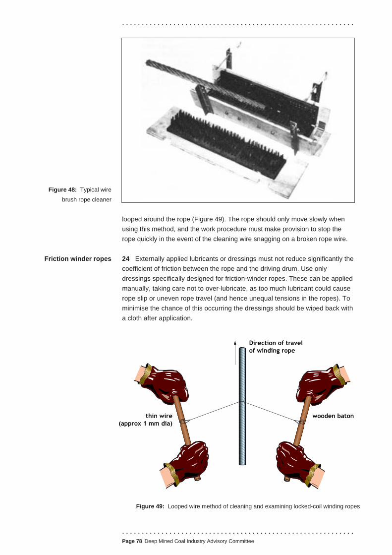
. . . . . . . . . . . . . . . . . . . . . . . . . . . . . . . . . . . . . . . . . . . . . . . . . . . . . . . . . . .
Figure 48: Typical wire
brush rope cleaner
Friction winder ropes
looped around the rope (Figure 49). The rope should only move slowly when
using this method, and the work procedure must make provision to stop the
rope quickly in the event of the cleaning wire snagging on a broken rope wire.
24 Externally applied lubricants or dressings must not reduce significantly the
coefficient of friction between the rope and the driving drum. Use only
dressings specifically designed for friction-winder ropes. These can be applied
manually, taking care not to over-lubricate, as too much lubricant could cause
rope slip or uneven rope travel (and hence unequal tensions in the ropes). To
minimise the chance of this occurring the dressings should be wiped back with
a cloth after application.
thin wire (approx 1 mm dia)
wooden baton
of winding rope Direction of travel
Figure 49: Looped wire method of cleaning and examining locked-coil winding ropes
. . . . . . . . . . . . . . . . . . . . . . . . . . . . . . . . . . . . . . . . . . . . . . . . . . . . . . . . . . . Page 78 Deep Mined Coal Industry Advisory Committee

. . . . . . . . . . . . . . . . . . . . . . . . . . . . . . . . . . . . . . . . . . . . . . . . . . . . . . . . . . .
Pressure lubrication
Balance ropes
Guide ropes
25 The interval between cleaning and application will vary depending on the
shaft environments in which the ropes run; the more corrosive the environment,
the shorter the interval between successive applications.
26 For multi-rope friction-winders, cleaning and re-lubrication can be phased; for
example, one rope per week or one per day, depending on operating conditions.
27 Despite the precautions taken during manufacture, newly installed ropes
sometimes exude excess lubricant and need frequent and careful examination
during the initial operating period. Use a cloth (moistened, if necessary, with an
appropriate solvent or specialised dressing) to remove any excess, then wipe
dry with a clean cloth. Avoid using drying agents such as gritty dusts.
28 On friction winding systems, the length of rope between the capping and
the drum, pulley or deflection sheave, whichever is the first point of contact,
may be further protected by a coating of lubricant with anticorrosive properties.
29 Externally applied dressings are unlikely to penetrate effectively the
internal layers of a locked coil rope. Pressure lubrication is a method of
injecting lubricant into ropes to replace the manufacturer’s lubricant which may
dry out in some shaft conditions. This can be for either the whole length of the
rope, or in specific areas where loss of the internal lubricant creates a rope
problem; for example, distortion of the outer cover of the length of rope on the
driving drum during the acceleration phase of the winding cycle.
30 The most appropriate time to apply pressure lubrication during the life of a
rope is normally determined by experience and advice from the rope
manufacturer. It is most beneficial at the end of the period when external
exudation of the internal lubricant has ceased, and when the lubricity of the
lubricant between the outer layer of the rope and the first of the inner layers
becomes ineffective.
31 Rope manufacturers will advise on the most appropriate pressure injection
technique.
32 Balance ropes, whether galvanised or not, should be kept well lubricated
for they often work in corrosive conditions. Cleaning is just as important as
lubricating for, if the lubricant cannot reach the rope surface, it is ineffective.
Relatively thin, spray-applied lubricants are most appropriate, as penetration is
better, and ropes remain cleaner and therefore easier to examine.
33 A commonly used type of dressing which gives good results in dry or damp
conditions, is a viscous, bitumen-based compound containing anti-rust,
tackiness, water repellent and de-watering additives.
34 In wet shafts, dressings with adhesive and emulsifying properties generally
give better results. Under the most severe conditions, where large amounts of
corrosive water are present, appropriate dressings will contain anti-rust and
. . . . . . . . . . . . . . . . . . . . . . . . . . . . . . . . . . . . . . . . . . . . . . . . . . . . . . . . . . .
.Page 79 Deep Mined Coal Industry Advisory Committee

. . . . . . . . . . . . . . . . . . . . . . . . . . . . . . . . . . . . . . . . . . . . . . . . . . . . . . . . . . .
dewatering additives, and no emulsifying agents. This type of lubricant is
difficult to apply, as it is necessary to thoroughly dry the rope surface prior to
application. However, it will last for a relatively long time before a fresh
application is needed.
Lubrication after 35 When a rope is capped or recapped with a white metal socket, it is possible
capping for some of the internal lubricant to be lost from the part of the rope adjacent to
the capping. This loss could encourage corrosion and fatigue of the wires at this
critical part of the rope; therefore, after completion of the capping process the
rope close to the mouth of the capping should be thoroughly relubricated. Rope
manufacturers have developed special lubricants for this purpose.
36 For fibre-cored ropes, a lubrication tube, fitted with a grease nipple, can be
cast into the white metal, having been previously pushed down the wire brush
and its end inserted into the fibre core. When the completed capping is cold,
lubricant is pumped in to replace any which may have melted out. The process
can be repeated as necessary during the life of the rope.
DETERIORATION IN SHAFT ROPES
37 The main forms of deterioration in shaft ropes are:
■ wear;
■ corrosion;
■ fatigue;
■ corrosion-fatigue;
■ surface embrittlement;
■ accidental damage and distortion, leading to local deterioration.
38 If a rope is of unsuitable type or construction, some of the above forms of
deterioration are more likely to occur. For instance, flexible type ropes having
small outer wires of less than 2 mm diameter are likely to suffer deterioration by
wear and corrosion. Ungalvanised ropes working under corrosive conditions
are almost certain to deteriorate by corrosion, especially if they are not kept
well lubricated at all times.
WEAR
39 Both external and internal wear occurs in all ropes; but if unusually heavy
wear occurs, engineers will need to identify and correct the cause. It should be
remembered that corrosion aids the advance of wear by helping to remove
. . . . . . . . . . . . . . . . . . . . . . . . . . . . . . . . . . . . . . . . . . . . . . . . . . . . . . . . . . . Page 80 Deep Mined Coal Industry Advisory Committee

External wear
. . . . . . . . . . . . . . . . . . . . . . . . . . . . . . . . . . . . . . . . . . . . . . . . . . . . . . . . . . .
steel, just as wear aids the advance of corrosion by removing the corrosion
scale and presenting a fresh surface for further corrosion.
40 External wear may take the form of abrasive wear (Figure 50a), in which
metal is removed from the crowns, or it may take the form of plastic wear
(Figure 50b), in which metal is displaced to form fins at the edges of the worn
Internal wear
Figures 51a-d: Examples
of nicks and grooves
Figure 50a: Abrasive Figure 50b: Plastic
crowns. Abrasive wear suggests that the rope has been rubbing too much
against some hard and abrasive surface which has rubbed off some of the steel
of the wire surfaces. Plastic wear suggests that the rope has been bearing
heavily on some hard surface, such as a pulley groove or drum. If there is only
a small contact area between the rope and the pulley or drum the wire surfaces
will deform into fins under the high pressure.
41 Wires in the rope interior which cross one another are bound to cut into
one another to some extent. If they are of opposite direction of lay they will
produce short indentations or nicks on one another; if they are of the same
direction of lay or in parallel lay they will produce long grooves. Figure 51
shows examples of nicks and grooves.
(a) (c)(b)
(d)
■ Figure 51a shows a simple nick.
■ Figure 51b shows a twinned nick caused by a crossing wire slightly
changing its point of contact with the wire shown, as a result of the rope
becoming loosely laid up.
■ Figure 51c shows a scuffed nick formed by a crossing but very loose wire
playing against the wire shown.
■ Figure 51d shows a long groove made by a wire of the same direction of
lay as the wire in the illustration.
42 Deep nicks or grooves, in the absence of corrosion, suggest that the wires
. . . . . . . . . . . . . . . . . . . . . . . . . . . . . . . . . . . . . . . . . . . . . . . . . . . . . . . . . . .
.Page 81 Deep Mined Coal Industry Advisory Committee

. . . . . . . . . . . . . . . . . . . . . . . . . . . . . . . . . . . . . . . . . . . . . . . . . . . . . . . . . . .
are being pressed together too heavily, or driven together too forcibly by impact.
Excessive pressure suggests that the rope is running in pulleys with too small a
diameter or too tight a groove. Impact indicates that the rope is striking against
some object, in which case there will probably be intermittent wear or damage
on the exterior. Impact on a moving rope can also produce martensitic surfaces
(see paragraphs 81 to 84) on the wires with subsequent wire breakage.
How wear leads to
breakage
43 When the round outer wires of a rope or strand (or the round outer rods of a
guide rope) become reduced to half their original depth by external wear or
corrosion, there are no longer any valleys remaining between adjacent outer wires,
and they can be readily
displaced by overriding one
another (Figure 52a).
44 When the wires
become reduced to less
than half their original
depth they will also be Figure 52a: Outer wires worn to half
displaced wire
reduced in width and will no
longer be in contact with their
neighbours, and there will then
be spaces or gaps between
them (Figure 52b). Such ‘loose’
wires are very easily moved
about in the rope and very
readily override one another. In Figure 52b: Outer wires worn to less than half
Space
addition, if internal wear (or
internal corrosion) has removed
the ‘undersides’ of the outer wires and
left those wires loose on their inner
wires (Figure 52c), then the outer wires
will be very loose indeed and will be
even more readily displaced. Figure 52c: Internal wear and corrosion
45 When wires become loose and override one another they will rapidly
break. If a rope is allowed to remain in service after it has reached a condition
in which wires have become loose and displaced, that rope will quickly proceed
to fail wire by wire until its strength is so reduced that it can no longer carry the
load and the remaining wires then break in tension. A rope in this highly
dangerous condition can be detected by looking to see if there are spaces
between or underneath its outer wires.
46 Six stages of failure, wire by wire, of a loosened rope which broke in
service are shown in Figure 53.
■ Figure 53a - The wires are so loose that spaces or ‘daylight’ can be seen
underneath some.
. . . . . . . . . . . . . . . . . . . . . . . . . . . . . . . . . . . . . . . . . . . . . . . . . . . . . . . . . . . Page 82 Deep Mined Coal Industry Advisory Committee

. . . . . . . . . . . . . . . . . . . . . . . . . . . . . . . . . . . . . . . . . . . . . . . . . . . . . . . . . . .
Figures 53a-f:
Stages of failure
(a)
(c)
(e)
(b)
(d)
(f)
■ Figure 53b - A loose wire has become displaced and bent into a Z-bend.
■ Figure 53c - A wire has broken at a Z-bend.
■ Figure 53d - The broken ends of a wire are protruding from the rope so
that they are liable to catch on obstructions.
■ Figure 53e - One of the broken ends has been hooked back on itself as a
result of catching on obstructions.
■ Figure 53f - That end has broken off short leaving a stubby flexion
(bending) fracture at an unworn part between strands, which is not the
original fracture at a greatly worn crown.
WEAR FRACTURES
47 When a rope breaks as a result of excessive wear many of the wires will
show sharp chisel-end fractures (Figure 54a) indicating that they have been
severed or almost severed by wear.
Figure 54a: Severed by wear Figure 54b: Flexion
48 Some wires will probably show stubby flexion (bending) fractures with
slightly hooked ends at unworn parts (Figure 54b). These too will have severed
by wear (or broken in some manner at their crowns) but their ends have
subsequently worn down.
. . . . . . . . . . . . . . . . . . . . . . . . . . . . . . . . . . . . . . . . . . . . . . . . . . . . . . . . . . .
.Page 83 Deep Mined Coal Industry Advisory Committee

. . . . . . . . . . . . . . . . . . . . . . . . . . . . . . . . . . . . . . . . . . . . . . . . . . . . . . . . . . .
49 Some wires will show typical tension fractures at less worn parts (Figure
54c). These wires will have failed in tension when the rope weakened to the
extent that it could no longer carry the load. A tension fracture can always be
recognised by the waisting
(necking), ie the reduction in
diameter, that occurs at the
broken end (Figures 55a
and 55b).
Figure 54c: Tension
Figure 55a: Wire wasting Figure 55b: Fractured ends
50 Corrosion is a major cause of deterioration in shaft ropes. As previously
mentioned, corrosion aids the advance of wear by helping to remove steel, just
as wear aids the advance of corrosion by removing the corrosion scale and
presenting a fresh surface for further corrosion. It is caused by water spray,
steam, fumes, acids, unsuitable lubricants, chloride solutions etc. Common salt
(sodium chloride) is very corrosive and can appear in solution in strata water
seeping into shafts, or in sea spray at coastal mines.
51 Corrosion affecting only a short length of a rope is indicative of a rope
being attacked while it is stationary. For instance, it may be caused by a leaking
service pipe or by condensation at the rope access hole in the hooding of an
upcast shaft. The high air velocity at the fan drift and air seals in a shaft can
also displace the rope lubricant, encouraging the onset of corrosion. Corrosion
may affect both the outside of the rope (external corrosion) and the inside of the
rope (internal corrosion). However, it can be controlled.
52 External corrosion usually takes the form of mild rust or scale and is seldom
more serious than it appears, unless winding shocks have contributed to
deterioration by corrosion-fatigue. It may take the form of pitting, as in the
Corrosion
External corrosion
Figure 56a: Severe pitting of a six strand rope
triangular strand rope in Figure 56a and the
outer wire of a locked coil rope in Figure
56b. It must be remembered that the
corroded wires are no stronger than their
weakest parts, ie at the largest or deepest
pits. It may also occur as edge pitting, in
which some or all of the pits lie at the sharp
edges of heavily worn crowns (ie at the
contacts between adjacent outer wires).
Figure 56b: Severe pitting on a fully locked
wire from a locked-coil rope
. . . . . . . . . . . . . . . . . . . . . . . . . . . . . . . . . . . . . . . . . . . . . . . . . . . . . . . . . . . Page 84 Deep Mined Coal Industry Advisory Committee

. . . . . . . . . . . . . . . . . . . . . . . . . . . . . . . . . . . . . . . . . . . . . . . . . . . . . . . . . . .
53 Edge pitting is more serious because it means that the corrosion is
attempting to enter the rope between the wires. In Figure 56a some of the pits
have attacked the sharp edges of the heavily worn crowns and have caused
those edges to become serrated or saw-edged. Thus, the rope in the illustration
may be in a much worse condition than the external pitting and wear would, at
first, suggest. The ropeman should, in such a case, suspect the presence of
internal corrosion.
Internal corrosion 54 Internal corrosion is dangerous and difficult to detect. People examining
ropes need the training, experience and knowledge to recognise the external
signs that may indicate its presence. Severe internal corrosion will cause the
loosening of wires by eroding their bearing surfaces in a similar manner to
severe internal wear (Figure 52c).
55 In Figure 56a the outer wires are loose; there are spaces between most of
these, some are riding high above the level of others and would soon override
them, and some are slightly displaced so as to leave a large space at one side
and none at the other. Corrosion has entered the rope and has attacked the
undersides of the outer wires, leaving those wires loose on their inner wires, as
in Figure 52c. In fact, the rope is approaching the highly dangerous condition of
the rope shown in Figure 53.
Corrosion fractures 56 When corrosion is so severe that the wires are
reduced to the extent that they can no longer carry their
intended load, they will break in tension and develop
tension fractures. However, the corrosion pitting and
scale may mask the waisting and make it difficult to Figure 56c:
recognise the type of fracture (Figure 56c). Corroded tension
Fatigue 57 Fatigue is the term used to describe the progressive deterioration of a rope
subjected to repeated loading. For example, if a rope is repeatedly loaded to
75% of its breaking strength it will not break immediately but it will eventually
break in fatigue, and its wires will show fatigue fractures (Figure 56d). Fatigue
fractures appear quite different from tension fractures.
58 If the rope is repeatedly loaded to 50% of its breaking strength it will still
Figure 56d: Fatigue break in fatigue, but only after a greater number of loadings because the
loadings are not so severe.
59 If the rope is repeatedly loaded to 25% of its breaking strength it will
probably never break, because the fatigue strength of rope wire under normal
operating conditions is about one-quarter of the breaking strength of the wire.
This means that if the repeated load in each wire can be kept below one-quarter
of its breaking strength, the wire and the rope will not deteriorate in fatigue.
60 The repeated loading in an individual rope wire comprises:
■ its share of the maximum tensile load;
. . . . . . . . . . . . . . . . . . . . . . . . . . . . . . . . . . . . . . . . . . . . . . . . . . . . . . . . . . .
.Page 85 Deep Mined Coal Industry Advisory Committee
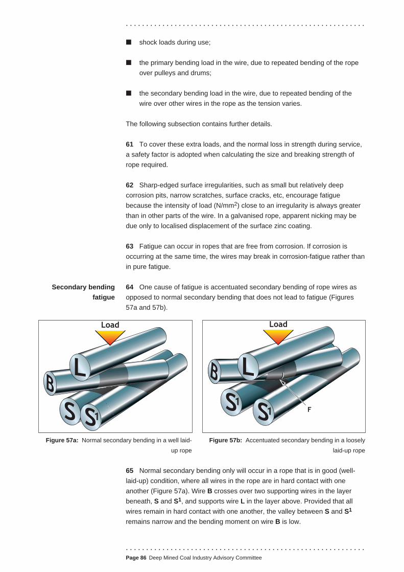
. . . . . . . . . . . . . . . . . . . . . . . . . . . . . . . . . . . . . . . . . . . . . . . . . . . . . . . . . . .
■ shock loads during use;
■ the primary bending load in the wire, due to repeated bending of the rope
over pulleys and drums;
■ the secondary bending load in the wire, due to repeated bending of the
wire over other wires in the rope as the tension varies.
The following subsection contains further details.
61 To cover these extra loads, and the normal loss in strength during service,
a safety factor is adopted when calculating the size and breaking strength of
rope required.
62 Sharp-edged surface irregularities, such as small but relatively deep
corrosion pits, narrow scratches, surface cracks, etc, encourage fatigue
because the intensity of load (N/mm2) close to an irregularity is always greater
than in other parts of the wire. In a galvanised rope, apparent nicking may be
due only to localised displacement of the surface zinc coating.
63 Fatigue can occur in ropes that are free from corrosion. If corrosion is
occurring at the same time, the wires may break in corrosion-fatigue rather than
in pure fatigue.
Secondary bending 64 One cause of fatigue is accentuated secondary bending of rope wires as
fatigue opposed to normal secondary bending that does not lead to fatigue (Figures
57a and 57b).
S S1
B L
Load
S1S1
L
Load
F
B
Figure 57a: Normal secondary bending in a well laid- Figure 57b: Accentuated secondary bending in a loosely
up rope laid-up rope
65 Normal secondary bending only will occur in a rope that is in good (well-
laid-up) condition, where all wires in the rope are in hard contact with one
another (Figure 57a). Wire B crosses over two supporting wires in the layer
beneath, S and S1, and supports wire L in the layer above. Provided that all
wires remain in hard contact with one another, the valley between S and S1
remains narrow and the bending moment on wire B is low.
. . . . . . . . . . . . . . . . . . . . . . . . . . . . . . . . . . . . . . . . . . . . . . . . . . . . . . . . . . . Page 86 Deep Mined Coal Industry Advisory Committee

. . . . . . . . . . . . . . . . . . . . . . . . . . . . . . . . . . . . . . . . . . . . . . . . . . . . . . . . . . .
66 If a rope is loosely laid up, either because it was supplied in that condition,
or through handling or use, the wires can move apart (Figure 57b). The gap
between the wires S and S1 is wider and deeper than before and leads to a
greater degree of bending or flexing in the bridge wire B for a given load. As
wire L is not now held in position by adjacent wires in the same layer, it can
slide down the bent wire B to the mid-span position, maximising the bending
moment on it. This causes pronounced flexing, which is repeated every time
the rope tension varies. Because the bridging wire B in a loose rope is
repeatedly bent to a much greater extent than in a well-laid-up rope, a fatigue
crack may develop on the stretched side of the bent wire at point F, on the
opposite side of the wire to the indentation (nick) due to the load applied by
wire L. The position of such a fatigue crack is a good indication that it was
caused by accentuated secondary bending.
67 Figure 58a shows part of a rope that broke in
fatigue. Four outer wires have been removed to reveal
that the remaining outer wires were so loose that the
two hacksaw blades (total thickness 1.3 mm) could be
inserted beneath them.
Figure 58a: Rope that
broke in fatigue 68 In Figure 58b one strand of the rope has been placed in front of a mirror so
that both sides of the strand can be seen at once. One wire on each side of the
strand has completely broken in
fatigue, where it has been in contact
with wires in adjacent strands and
caused a line of nicks on its surface.
The fatigue cracks leading to these
wire fractures did not start in the nicks;
all the cracks in that rope will have
started on the opposite (inside) side of
the wire, and some spread across the
wire to reach the nicks.
69 This point is best illustrated by choosing a wire which is cracked but not
completely broken. In Figure 58c, a cracked wire from the rope has been
placed in front of a mirror; the fatigue
crack is directly on the opposite side of
the wire to the nick on the contact side.
This indicates that the fatigue in that rope
was due to accentuated secondary
bending which, in turn, was due to either
loose or loosened lay.
70 In this particular case, the nature of the nicking indicates that the accentuated
secondary bending is due to loosened lay. In Figure 58c, the two nicks are not
normal, and are twinned nicks, each being made up of two mainly-overlapping
nicks. The cause of this was a permanent change in the contact points between
this wire and other wires, which could only occur in a loosened rope.
Figure 58b: Rope that
broke in fatigue
Figure 58c: Rope that
broke in fatigue
. . . . . . . . . . . . . . . . . . . . . . . . . . . . . . . . . . . . . . . . . . . . . . . . . . . . . . . . . . .
.Page 87 Deep Mined Coal Industry Advisory Committee

. . . . . . . . . . . . . . . . . . . . . . . . . . . . . . . . . . . . . . . . . . . . . . . . . . . . . . . . . . .
71 Furthermore, the two long grooves that cross the crack were made by the
two supporting inner wires, S and S1 in Figure 57b. These grooves are wider at
the crack than elsewhere, indicating that the wire was repeatedly pressed down
into the valley between the supporting wires, widening the grooves. The two
grooves overlap, and the crack is halfway along the length of the overlap; this
means that the crack (and the nick opposite) were at mid-span in the bridging
wire B in Figure 57b, which also formed a greatly skewed bridge. The second
nick, which has no crack opposite to it, is due to the nick being opposite only
one groove, and so opposite a part which was riding right on top of one inner
wire and, therefore, at one end of the small bridge where it could not be
repeatedly bent down into the valley.
72 When a wire is deteriorating by fatigue it will show no signs of that
deterioration until it has completed more than 90% of the loading cycles
necessary to break it in fatigue. Then a small crack will appear on the wire
surface, so small and fine that the person inspecting or
examining the rope will have little chance of finding it unless
looking specifically for such evidence. Figure 59 shows several
fatigue cracks in an inner layer of wires of a locked coil rope.
As the cracks deepen, the wires will break with a partly
splintered end.
73 Figure 60 shows a wire
breaking in this way at a fatigue
crack. The splintered part of the
fracture (Figures 60b and 60c)
has nothing to do with fatigue; it
shows only that the final fracture
of the cracked wire occurred in
bending. The smooth, flat-
surfaced part of the fracture is
the part that formed one side of
the fatigue crack. The smooth
part is usually dark or
discoloured, because the crack
existed for some time before the
wire broke. If the cracked wire is
not subjected to bending in Figures 60a-c: Stages in the breaking of a wire
service, the fatigue crack will at a fatigue crack
extend completely or almost
completely across the wire, giving a smooth flat-surfaced fracture with little or no
splintered part.
(a)
(b)
(c)
74 In all cases the fracture will be very abrupt or sharp-edged, without any of
the waisting found in tension fractures, and at least a small part of its end
surface will be smooth and probably dark in colour. These are the signs of a
fatigue fracture in a wire, just as waisting is the sign of a tensile fracture.
Fatigue fractures
Figure 59: Fatigue cracks
in an inner layer of a
locked-coil rope
. . . . . . . . . . . . . . . . . . . . . . . . . . . . . . . . . . . . . . . . . . . . . . . . . . . . . . . . . . . Page 88 Deep Mined Coal Industry Advisory Committee
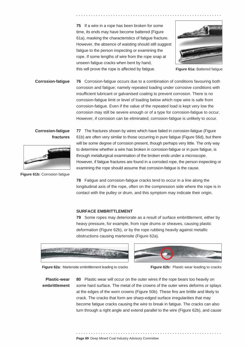
. . . . . . . . . . . . . . . . . . . . . . . . . . . . . . . . . . . . . . . . . . . . . . . . . . . . . . . . . . .
Corrosion-fatigue
Corrosion-fatigue
fractures
Figure 61b: Corrosion fatigue
75 If a wire in a rope has been broken for some
time, its ends may have become battered (Figure
61a), masking the characteristics of fatigue fracture.
However, the absence of waisting should still suggest
fatigue to the person inspecting or examining the
rope. If some lengths of wire from the rope snap at
unseen fatigue cracks when bent by hand,
this will prove the rope is affected by fatigue. Figure 61a: Battered fatigue
76 Corrosion-fatigue occurs due to a combination of conditions favouring both
corrosion and fatigue; namely repeated loading under corrosive conditions with
insufficient lubricant or galvanised coating to prevent corrosion. There is no
corrosion-fatigue limit or level of loading below which rope wire is safe from
corrosion-fatigue. Even if the value of the repeated load is kept very low the
corrosion may still be severe enough or of a type for corrosion-fatigue to occur.
However, if corrosion can be eliminated, corrosion-fatigue is unlikely to occur.
77 The fractures shown by wires which have failed in corrosion-fatigue (Figure
61b) are often very similar to those occurring in pure fatigue (Figure 56d), but there
will be some degree of corrosion present, though perhaps very little. The only way
to determine whether a wire has broken in corrosion-fatigue or in pure fatigue, is
through metallurgical examination of the broken ends under a microscope.
However, if fatigue fractures are found in a corroded rope, the person inspecting or
examining the rope should assume that corrosion-fatigue is the cause.
78 Fatigue and corrosion-fatigue cracks tend to occur in a line along the
longitudinal axis of the rope, often on the compression side where the rope is in
contact with the pulley or drum, and this symptom may indicate their origin.
SURFACE EMBRITTLEMENT
79 Some ropes may deteriorate as a result of surface embrittlement, either by
heavy pressure, for example, from rope drums or sheaves, causing plastic
deformation (Figure 62b), or by the rope rubbing heavily against metallic
obstructions causing martensite (Figure 62a).
Figure 62a: Martensite embrittlement leading to cracks Figure 62b: Plastic wear leading to cracks
Plastic-wear 80 Plastic wear will occur on the outer wires if the rope bears too heavily on
embrittlement some hard surface. The metal of the crowns of the outer wires deforms or splays
at the edges of the worn crowns (Figure 50b). These fins are brittle and likely to
crack. The cracks that form are sharp-edged surface irregularities that may
become fatigue cracks causing the wire to break in fatigue. The cracks can also
turn through a right angle and extend parallel to the wire (Figure 62b), and cause
. . . . . . . . . . . . . . . . . . . . . . . . . . . . . . . . . . . . . . . . . . . . . . . . . . . . . . . . . . .
.Page 89 Deep Mined Coal Industry Advisory Committee

Martensitic
embrittlement
Figures 62d:
Martensitic embrittlement
. . . . . . . . . . . . . . . . . . . . . . . . . . . . . . . .
the fins to flake off. In the case of plastic-
wear embrittlement, it is a matter of chance
whether the wire breaks (Figure 62c) or the
embrittled fin flakes off. Figure 62c:
Plastic-wear embrittlement
81 Where martensitic embrittlement occurs, for
instance if a balance rope is rubbing on a steel joist, the situation should be
corrected by repositioning the joist or fixing a rubbing timber to the joist that can
be readily replaced as necessary when wear occurs. The person inspecting or
examining the rope should recognise that martensitic embrittlement may have
occurred and closely examine the rope with a magnifying glass for fine
martensitic cracks on the worn crowns. The presence of such cracks should
trigger a more frequent examination, and the withdrawal of the rope from service
as soon as the wires begin to break at the worn crowns.
82 Martensite is a very hard and brittle form of steel produced when steel is
heated to a high temperature (ie above 700°C for steels used in wire rope
manufacture) and then suddenly cooled. It is like the steel of which files are
made; if a file is dropped or bent it will break, for it has virtually no ductility. If a
fast moving rope rubs even lightly against a metal obstruction, or if a slower
moving rope grinds heavily against such an obstruction, the resulting friction can
heat almost spontaneously the surface of the rubbed wires to above 700°C, but
only to a depth of about 0.02 mm. As soon as the source of friction is removed
the heat is quickly carried away to the colder metal of the wire just underneath
the heated surface. The surface of the wire cools very quickly and results in the
surface becoming brittle martensite. As the crowns of the outer wires are in
hardest contact with the metal obstruction, the martensite tends to form there.
83 When the wire is subsequently bent, the brittle surface will develop a series
of cracks along or near its centre line (Figure 62d), each about 0.02 mm deep
and running across the worn crown of the wire. These cracks will in time become
fatigue cracks, leading to wires breaking in fatigue. Martensitic embrittlement is
therefore a potentially dangerous form of deterioration if it is not discovered.
84 When corrosion affects a martensitic surface it enters the cracks and
attacks the normal steel below the surface rather than the hard martensitic
steel. A corrosion pit forms at the bottom of each crack and extends to join up
Figure 62e: Chain pitting with a pit at the bottom of the next nearby crack. The undermined surface then
on a wire flakes off leaving a chain or chains of elongated corrosion pits following the
strip(s) of martensite on the surface. Such chain pitting (Figure 62e) is one of
the signs of martensitic embrittlement, and is different from the normal random
pitting shown in Figure 56a.
. . . . . . . . . . . . . . . . . . . . . . . . . . . . . . . . . . . . . . . . . . . . . . . . . . . . . . . . . . . Page 90 Deep Mined Coal Industry Advisory Committee

Surface embrittlement
fractures
. . . . . . . . . . . . . . . . . . . . . . . . . . . . . . . . . . . . . . . . . . . . . . . . . . . . . . . . . . .
85 Surface embrittlement fractures are always fatigue type fractures, because
they form only when the original surface cracks become fatigue cracks of
sufficient depth to break the wires. They are always situated at the worn crowns
of the wires and nowhere else.
86 Those examining ropes can detect surface embrittlement by removing
some unbroken wires from a suspect rope and bending one wire to stretch the
worn crown. If the surface of the worn crown is embrittled cracks will open, and
if bending is continued the wire will break. If the cracks start to open at the
edges of the worn crown where there are fins, then the rope has plastic-wear
embrittlement. If the cracks start to open at or near the centreline of the worn
crown and not at the edges, then the rope has martensitic embrittlement.
(a)
(b)
(c)
(d)
ACCIDENTAL DAMAGE AND DISTORTION
87 Accidental damage and distortion are not
really forms of deterioration, but it is very
important that the person inspecting or
examining the rope realises that they may
lead to unexpectedly rapid deterioration at the
affected part.
88 A rope which has been dented by an
impact may still appear to be in reasonably
good condition, but fatigue may subsequently
develop at the damaged part. If the impact has
permanently deformed some of the wires into
elbow-shaped bends, then every time the load
varies during operation the bent wires will partly
straighten and then return to their bent
condition. In other words they will be repeatedly
bent at one point, as in the case of accentuated
secondary bending, and they will probably
break in fatigue. If the impact has forced apart
some wires or strands, leaving the rope open at
Figures 63a-d: Kinking that place, moisture will enter readily and
internal corrosion or corrosion-fatigue may develop at the damaged part.
Kinking 89 A true kink is formed when a rope goes slack, forms itself into a close loop,
and is pulled tight. The resulting kink forms a short but very tightly twisted
spiral, with a shortened length of lay. The elbow-shaped deformations formed
can result in concentrated and rapid wear on their outer sides. Figure 63 shows
a kink at four different stages of failure in the same rope.
90 If a rope is permanently deformed into an elbow-shaped bend, but with no
change in length of lay at the deformation, then the deformation is not a true kink
. . . . . . . . . . . . . . . . . . . . . . . . . . . . . . . . . . . . . . . . . . . . . . . . . . . . . . . . . . .
.Page 91 Deep Mined Coal Industry Advisory Committee
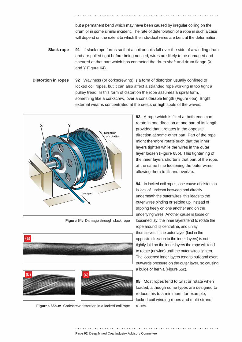
. . . . . . . . . . . . . . . . . . . . . . . . . . . . . . . . . . . . . . . . . . . . . . . . . . . . . . . . . . .
. . . . . . . . . . . . . . . . . . . . . . . . . . . . . . . . . . . . . . . . . . . . . . . . . . . . . . . . . . .Page 92 Deep Mined Coal Industry Advisory Committee
but a permanent bend which may have been caused by irregular coiling on the
drum or in some similar incident. The rate of deterioration of a rope in such a case
will depend on the extent to which the individual wires are bent at the deformation.
91 If slack rope forms so that a coil or coils fall over the side of a winding drum
and are pulled tight before being noticed, wires are likely to be damaged and
sheared at that part which has contacted the drum shaft and drum flange (X
and Y Figure 64).
92 Waviness (or corkscrewing) is a form of distortion usually confined to
locked coil ropes, but it can also affect a stranded rope working in too tight a
pulley tread. In this form of distortion the rope assumes a spiral form,
something like a corkscrew, over a considerable length (Figure 65a). Bright
external wear is concentrated at the crests or high spots of the waves.
93 A rope which is fixed at both ends can
rotate in one direction at one part of its length
provided that it rotates in the opposite
direction at some other part. Part of the rope
might therefore rotate such that the inner
layers tighten while the wires in the outer
layer loosen (Figure 65b). This tightening of
the inner layers shortens that part of the rope,
at the same time loosening the outer wires
allowing them to lift and overlap.
94 In locked coil ropes, one cause of distortion
is lack of lubricant between and directly
underneath the outer wires; this leads to the
outer wires binding or seizing up, instead of
slipping freely on one another and on the
underlying wires. Another cause is loose or
loosened lay; the inner layers tend to rotate the
rope around its centreline, and unlay
themselves. If the outer layer (laid in the
opposite direction to the inner layers) is not
tightly laid on the inner layers the rope will tend
to rotate (unwind) until the outer wires tighten.
The loosened inner layers tend to bulk and exert
outwards pressure on the outer layer, so causing
a bulge or hernia (Figure 65c).
95 Most ropes tend to twist or rotate when
loaded, although some types are designed to
reduce this to a minimum; for example,
locked coil winding ropes and multi-strand
ropes.
Slack rope
Distortion in ropes
Direction
of rotation
YX
to capel
Figure 64: Damage through slack rope
Figures 65a-c: Corkscrew distortion in a locked-coil rope
(a)
(b) (c)

. . . . . . . . . . . . . . . . . . . . . . . . . . . . . . . . . . . . . . . . . . . . . . . . . . . . . . . . . . .
Fractures at damage
and distortions
96 The amount of twist depends upon the load applied and the length of the
rope. In the case of winding ropes operating without balance ropes, the length
of rope and the tension decrease as the conveyance is wound up the shaft, and
therefore the amount of twist will vary along the rope’s length.
97 Locked coil ropes less than 38 mm diameter have fewer layers of wires
and are less easily affected by those factors which can cause waviness
corrosion, drying out of lubricant, pinching in pulleys or incorrect handling. This
is one reason why in modern friction winding installations several small winding
ropes are used (multi-rope friction winding) instead of one large rope (single
rope friction winding).
98 Another cause of rope rotation is a large fleet angle because, to take the
case of a descending rope, the rope will first land on the flange of the
headframe pulley and then roll into the tread as it travels around the pulley.
This rolling again involves rotation of the rope.
99 In tower mounted friction winders, misalignment of the driving groove and
the deflection sheave will create a constant fleet angle causing the rope to
rotate in one direction throughout the wind.
100 There may be no wire fractures at damaged or deformed parts unless the
rope is allowed to remain in use too long after deformation. If wire fractures
appear, their type will depend on the nature of the damage or deformation and
on the working conditions. For instance, a kinked winding rope will develop
fatigue fractures because a winding rope wears only slowly and fatigue will,
therefore, have time to develop. People who inspect ropes should examine
thoroughly any deformation they find and assess how the deformed wires will
act during further service:
■ If they are repeatedly bent and straightened, they are liable to break in
fatigue.
■ If they protrude above the level of other wires, localised wear could occur.
■ If they have been displaced leaving the rope open, localised internal
corrosion might occur.
101 Even if there are no broken wires, a distorted rope may still cause
excessive sheave wear.
REPAIR OF LOCKED COIL WINDING ROPES
102 If a broken wire is detected in the outer layer of a locked coil winding rope,
it should be repaired by lifting out the wire over a distance of approximately
500 mm either side of the break, then either annealing and caulking them back
. . . . . . . . . . . . . . . . . . . . . . . . . . . . . . . . . . . . . . . . . . . . . . . . . . . . . . . . . . .
.Page 93 Deep Mined Coal Industry Advisory Committee

. . . . . . . . . . . . . . . . . . . . . . . . . . . . . . . . . . . . . . . . . . . . . . . . . . . . . . . . . . .
into position, leaving a small gap between the wire ends, or by brazing in a new
length of wire. These are highly skilled operations that only the rope
manufacturer’s personnel should undertake.
NON-DESTRUCTIVE TESTING (NDT)
103 The non-destructive testing (NDT) of ferromagnetic wire ropes is a
specialised operation often involving the use of equipment purpose-designed
for particular types of rope. Appendix 6 contains an outline procedure for the
NDT of locked coil ropes. Where applicable, it can also be used as a guide for
the NDT of other rope types.
104 Different rope constructions are used for different applications in mines and
some of these present more difficult NDT and visual examination problems than
others. This particularly applies to locked coil and half locked coil ropes which
have a greater density of wires than those in a stranded rope of the same
diameter. It is essential therefore to select appropriate NDT equipment. There
are a number of different instruments that are suitable for the NDT of stranded
ropes, but there is a more limited choice for locked coil ropes.
105 NDT can be carried out using alternating current (AC), direct current (DC)
and permanent magnet type instruments. Data are presented in graphical form
and will indicate the presence of broken wires, internal and external corrosion
and general wear in a rope. If a rope is severely corroded, the NDT instrument
may not detect internal broken wires.
106 It is also essential to recognise that winding ropes are safety critical
components and as such, testing and the reporting of tests should only be
carried out by suitably trained and experienced personnel, which is also
covered in Appendix 6. European Standard prEN 12927-8, Safety requirements
for passenger transportation by rope - Part 8: Non- destructive testing20 also
provides valuable advice in the practice of NDT of wire ropes.
107 It should be understood that the NDT is an aid to visual inspection, but it
has the advantage of being able to detect internal or hidden defects. It is
therefore useful as a routine periodic condition monitoring test providing data to
inform judgements on the condition of the rope. Although data can be obtained
from a single test to ascertain the condition of the rope at the time of test, the
main advantage of NDT lies in the collection of data as a result of routine
periodic monitoring. Comparing data from routine periodic NDT allows any rope
deterioration to be detected at an early stage, and the rate of deterioration can
be assessed during its service life.
108 Where it is intended to monitor the condition of a winding rope throughout
its operational life then it is recommended that an NDT be carried out on the
winding rope when first installed in order to reveal any manufacturing
discrepancies, and to provide a database against which the findings of further
. . . . . . . . . . . . . . . . . . . . . . . . . . . . . . . . . . . . . . . . . . . . . . . . . . . . . . . . . . . Page 94 Deep Mined Coal Industry Advisory Committee

. . . . . . . . . . . . . . . . . . . . . . . . . . . . . . . . . . . . . . . . . . . . . . . . . . . . . . . . . . .
tests may be evaluated. The provision of such a condition monitored database
is an essential requirement when applying to the Health and Safety Executive
for permission to use a rope beyond the end of its specified life.
109 The interpretation of the results requires expert knowledge. Rope
manufacturers and specialist testing companies can provide an NDT expert
service.
110 An ultrasonic testing method is available for the NDT of resin capped guide
ropes in the area of the headframe capping, where fatigue effects are most
likely and where other NDT methods described above are unsuitable. It is
applied both to the outer wires of the rope, immediately below the guide rope
capping, and to the inner wires of the rope where they protrude above the top
of the capping, and can detect broken wires in the rope in that area. It is good
practice to undertake such tests periodically; the interval between tests
depending on shaft operating and environmental conditions. NDT should also
be used when considering an extension to the normal recapping period of five
years. Ultrasonic NDT is unreliable for white metal capped guide ropes.
WHEN TO DISCARD A ROPE
111 In order to decide when a rope should be discarded it is necessary to take
into account the state of the rope and the conditions under which it works. A
rope which shows some deterioration but which has done little work may be
suitable for continued use, whereas another rope with the same degree of
deterioration, but which has done a great deal of work may have reached the
end of its useful life, as the onset of fatigue or corrosion-fatigue will be much
more likely in the busy rope.
112 As a general rule a shaft rope should be taken out of service when any one
of the following occurs:
■ when the factor of safety has become too low (when the reserve of
strength is no longer sufficient to ensure that the rope can safely withstand
the repeated shock loads, bends, etc);
■ when the loss in rope strength due to wear, corrosion, or both is
approaching one-sixth (or 16%) of the original strength;
■ when the loss in rope strength due to fatigue, corrosion-fatigue, or surface
embrittlement, or due to cracked or broken wires of any kind, is approaching
one-tenth (or 10%) of the original strength. The loss in strength may be
estimated by regarding all broken or cracked wires within a length of two
rope lays as no longer contributing any strength to that part of the rope;
■ when the outer wires have lost about one-third (or 33%) of their depth as a
result of any form of deterioration;
. . . . . . . . . . . . . . . . . . . . . . . . . . . . . . . . . . . . . . . . . . . . . . . . . . . . . . . . . . .
.Page 95 Deep Mined Coal Industry Advisory Committee

Figure 66: Fatigue cracks
(within circles) along one
side of a locked-coil rope
. . . . . . . . . . . . . . . . . . . . . . . . . . . . . . . . . . . . . . . . . . . . . . . . . . . . . . . . . . .
■ when the outer wires are becoming loose and displaced for any reason;
■ when the rope has become kinked or otherwise deformed, distorted, or
damaged, and the affected part cannot be cut out;
■ when the rope has been subjected to a severe overwind or overload, or to
severe shock loading, as a result of an accident or incident;
■ when an examination or NDT of the rope leaves any doubt as to its safety
on any grounds;
■ when a rope, which is still in good condition reaches the end of its specified
life (see paragraph 129 to 130 of the ACOP to the 1993 Regulations for
further guidance3).
TYPES OF DETERIORATION IN SHAFT ROPES
113 Some of the guidance in this section is in repetition of that given earlier, but is
provided for completeness and ease of reference to the accompanying tables.
TYPES OF DETERIORATION AFFECTING WINDING ROPES
114 Table 14 lists the main types of deterioration found in winding ropes
together with the possible causes and suggested remedies.
Deterioration Position and extent Possible cause Possible remedy
found of deformation
Wear, external Localised along one side Rope slip on pulley as a result of Change in winding procedure
abrasive rapid braking of winding machine
(Fig 50a)
Intermittent Rope vibrating excessively and Check drum surface for irregularities
rubbing against (vibrations may arise at crossover
points on multi-layer winders)
Plastic
deformation
External (Fig 50b) or
internal (severe
interstrand nicking)
Obstructions Replace round strand rope by
triangular strand or locked coil, or
use larger diameter drum (see
Table 15) or use rope of more
flexible construction
Pulley groove diameter should be
at least 5 to 10% greater than the
actual rope diameter
. . . . . . . . . . . . . . . . . . . . . . . . . . . . . . . . . . . . . . . . . . . . . . . . . . . . . . . . . . . Page 96 Deep Mined Coal Industry Advisory Committee

. . . . . . . . . . . . . . . . . . . . . . . . . . . . . . . . . . . . . . . . . . . . . . . . . . . . . . . . . . .
Deterioration Position and extent Possible cause Possible remedy
found of deformation
Corrosion Localised Cages always parked in same Vary parking positions; attempt to
(Fig 56 a-c) positions; same part of rope always remove or reduce cause of
exposed to corrosive conditions corrosion
Throughout length of rope Inadequate lubrication More frequent lubrication or use of
more effective lubricant
Severe environmental conditions Use of galvanised rope; more
frequent lubrication; some form of
weather protection, if possible
Corrosion At any part Conditions likely to cause fatigue Removal of conditions likely to
fatigue together with those favouring at encourage corrosion and fatigue
least some degree of corrosion
Numerous
broken wires,
all showing
evidence of
fatigue
(i) throughout rope a) excessive rope vibrations caused
by misaligned rigid guides or
uneven drum surfaces, or
b) too small a drum or pulley
diameter, or
Improvements to guides or drum
Using rope of more flexible
construction
c) excessive looseness in rope;
secondary bending, or
Consider using ropes of equal lay
d) overloading of rope Check loads
(ii) along two lines parallel
to one another and at
about 140o round rope
circumference from
one another (Fig 66)
too small a pulley groove Enlarge pulley groove diameter to
at least 5 to 10% greater than the
actual rope diameter
(iii) at neck of capping
(Figs 42 and 68)
(a) frequency of winding cycle Increase frequency of recapping
until cause of broken wires can be
found remedied
(b) insufficient length of undisturbed
rope within mouth of socket
Use correct capping procedures
(c) wires in brush not properly
cleaned causing uneven
distribution of load
Wire brush, always very thoroughly
degreased before being capped
with resin or white metal
. . . . . . . . . . . . . . . . . . . . . . . . . . . . . . . . . . . . . . . . . . . . . . . . . . . . . . . . . . .
.Page 97 Deep Mined Coal Industry Advisory Committee
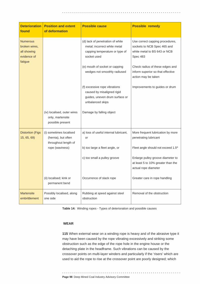
. . . . . . . . . . . . . . . . . . . . . . . . . . . . . . . . . . . . . . . . . . . . . . . . . . . . . . . . . . .
Deterioration
found
Position and extent
of deformation
Possible cause Possible remedy
Numerous
broken wires,
all showing
evidence of
fatigue
(d) lack of penetration of white
metal; incorrect white metal
capping temperature or type of
socket used
(e) mouth of socket or capping
wedges not smoothly radiused
Use correct capping procedures,
sockets to NCB Spec 465 and
white metal to BS 643 or NCB
Spec 483
Check radius of these edges and
inform superior so that effective
action may be taken
(f) excessive rope vibrations
caused by misaligned rigid
guides, uneven drum surface or
unbalanced skips
Improvements to guides or drum
(iv) localised, outer wires
only, martensite
possible present
Damage by falling object
Distortion (Figs
15, 65, 69)
(i) sometimes localised
(hernia), but often
throughout length of
rope (waviness)
a) loss of useful internal lubricant,
or
b) too large a fleet angle, or
More frequent lubrication by more
penetrating lubricant
Fleet angle should not exceed 1.5o
c) too small a pulley groove Enlarge pulley groove diameter to
at least 5 to 10% greater than the
actual rope diameter
(ii) localised; kink or
permanent bend
Occurrence of slack rope Greater care in rope handling
Martensite Possibly localised, along Rubbing at speed against steel Removal of the obstruction
embrittlement one side obstruction
Table 14: Winding ropes - Types of deterioration and possible causes
WEAR
115 When external wear on a winding rope is heavy and of the abrasive type it
may have been caused by the rope vibrating excessively and striking some
obstruction such as the edge of the rope hole in the engine house or the
detaching plate in the headframe. Such vibrations can be caused by the
crossover points on multi-layer winders and particularly if the ‘risers’ which are
used to aid the rope to rise at the crossover point are poorly designed; which
. . . . . . . . . . . . . . . . . . . . . . . . . . . . . . . . . . . . . . . . . . . . . . . . . . . . . . . . . . . Page 98 Deep Mined Coal Industry Advisory Committee

. . . . . . . . . . . . . . . . . . . . . . . . . . . . . . . . . . . . . . . . . . . . . . . . . . . . . . . . . . .
may also cause premature wear on the rope at that point. Similar wear can also
be caused by the rope slipping on the pulley during braking, etc.
116 Plastic deformation on a rope, either externally or internally, is usually the
result of high bearing pressures, against the drum, against other coils, or in a
pulley groove which is too small for the rope. A small ratio (drum to rope),
ungrooved steel-surfaced drum will provide only a small area of contact for
each coil of rope and could cause plastic deformation.
117 The values given in Table 15 are the minimum drum and pulley/rope
diameter ratios recommended for all winding ropes.
Rope type
Locked coil ropes
Rope size
< 26 mm
Ratio
80
26-44 mm 100
> 44 mm 120
Stranded ropes All sizes 80
Table 15: Minimum drum and pulley/rope diameter ratios for winding ropes
118 Alternatively, the wear may be a combination of plastic deformation and
abrasion as a result of the rope bearing heavily against the flange of the pulley,
or against the next coil on the drum when the rope makes its largest fleet angle
with the pulley; this angle should not exceed 1.5o (1 in 38).
119 A round strand rope which coils on top of itself in two or more layers on
the drum will tend to show plastic deformation, for there is only wire to wire
contact, of very little area, between a coil of rope in the top layer and coils in
the under layer. A triangular-strand rope or a locked coil rope has a greater
bearing surface and a change to such a rope may avoid further plastic
deformation. Such damage may also be caused by a pulley groove which is
the wrong size for the rope; the diameter of the groove for a locked coil rope
that operates on steel or cast iron pulleys should be at least 5% to 10%
greater than the nominal diameter of the rope and for a stranded rope that
value is 7.5% to 10%. Where polyurethane inserts are installed on headgear
pulleys or friction winder deflection sheaves the groove radius should be
maintained within the range of 12 to 20% of the actual rope radius. A more
specific value within that range is dependent on the grade and hardness of the
polyurethane and advice on the matter should be sought from the supplier of
the inserts and the rope manufacturers.
120 If a rope is subjected to corrosive conditions as well as wear, the rate of
deterioration will be increased. The external wear will continuously remove the
outer layer of corrosion products leaving fresh metal open to attack whilst
. . . . . . . . . . . . . . . . . . . . . . . . . . . . . . . . . . . . . . . . . . . . . . . . . . . . . . . . . . .
.Page 99 Deep Mined Coal Industry Advisory Committee

. . . . . . . . . . . . . . . . . . . . . . . . . . . . . . . . . . . . . . . . . . . . . . . . . . . . . . . . . . .
corrosion will deepen further the nicks and grooves at contact points between
wires within the rope.
Corrosion 121 The most efficient method of preventing corrosion is, of course, to remove
all causes of corrosion, but that is not always feasible. However, leaking pipes
should not be allowed to blow steam on a rope, nor should water be allowed to
drip on a rope if it can be collected and led elsewhere. The parking positions of
the conveyances during idle periods should be changed from time to time so as
to prevent any one part of the rope length being exposed to the most corrosive
location for too long.
122 Ropes should be kept well lubricated at all times, as a defence against
corrosion, unless there is a sound reason against lubrication. For instance, the
outside of a friction-winding rope must not be permitted to become greasy in
case it slips on the driving sheave, but the engineer may agree to different parts
of the rope length being lubricated at different times, using a thin proprietary oil
which will penetrate the rope to some extent and which can be wiped off the
exterior before winding is restarted.
123 In general, only rope lubricants should be used on ropes. Special lubricants
exist which contain additives to improve their usefulness such as substances that
help to prevent corrosion (rust inhibitors) and those that get the lubricant into
direct contact with the wire surface even when the surface is wet (water
repellents). Rope manufacturers and oil companies will advise on the use of such
lubricants or other corrosion inhibitors. Every effort should be made to ensure that
the service dressings are compatible with the manufacturer’s original lubricant.
124 The best defence against corrosion is the use of ropes of galvanised
finish. Even if there were no lubricant present, the zinc coating on the wires of
such ropes would protect the steel for many months under corrosive conditions,
but eventually the zinc would be corroded away. Unless there are sound
reasons to the contrary (eg friction winders) galvanised ropes should be kept
well lubricated at all times, particularly in those areas that may be subject to
corrosion when the conveyances are in their park positions ie, shaft insets, fan
drifts, shaft air heaters, rope holes in towers or headgears. Specialist products
may be available for additional protection in difficult areas, however every effort
should be made to ensure that such products are compatible with the
manufacturer’s original lubricant. Under such conditions the zinc coatings will
protect the wires throughout the life of the rope except, perhaps, on the rope
exterior where the zinc may be removed by wear to an extent which permits
corrosion of the steel. The exterior, however, can always be readily examined.
Fatigue 125 Fatigue is one of the causes for the premature discard of winding ropes.
The onset of fatigue can be delayed if precautions are taken to avoid winding
shocks, sharp bending of the rope around pulleys and drums of insufficient
size, loosening of the lay of the rope with consequent accentuation of
secondary bending and by correct selection of the rope to suit the application.
. . . . . . . . . . . . . . . . . . . . . . . . . . . . . . . . . . . . . . . . . . . . . . . . . . . . . . . . . . . Page 100 Deep Mined Coal Industry Advisory Committee

. . . . . . . . . . . . . . . . . . . . . . . . . . . . . . . . . . . . . . . . . . . . . . . . . . . . . . . . . . .
1 second
Figure 67a: Vertical acceleration
1 second
Figure 67b: Horizontal acceleration
126 Severe rope oscillations, indicated by
peaks on the decelerometer records for that
installation (Figure 67) cause increased
stresses in the rope leading to broken wires
either throughout the working length or
localised at the capping as a result of sideways
flexion. The mouth of a resin or white metal
socket or the narrow end of capping wedges
should always be smoothly radiused.
127 If, at the beginning of a wind, the cage is
Figure 68: Front and rear views showing broken outer wires on a accelerated smoothly, the resulting winding
guide rope where rope was in contact with corners of wedges shocks will be small. If, however, slack rope
(position of wedges indicated by broken lines) or slack chains are abruptly snatched tight,
the load on the rope may be doubled for a
moment and the cage will bounce on the rope, causing further shocks; which is
one reason why the rope length should be kept properly adjusted. Badly
aligned rigid guides or unbalanced skips may set up cage chatter and also
cause wires to fail in fatigue near the capping (Figure 68).
Corrosion-fatigue 128 Corrosion-fatigue occurs in conditions which favour both corrosion and
fatigue. It is the most dangerous form of deterioration since there is no lower
limit of loading below which the rope wire is safe from such deterioration.
However, if corrosion can be eliminated, corrosion-fatigue cannot occur and
. . . . . . . . . . . . . . . . . . . . . . . . . . . . . . . . . . . . . . . . . . . . . . . . . . . . . . . . . . .
.Page 101 Deep Mined Coal Industry Advisory Committee
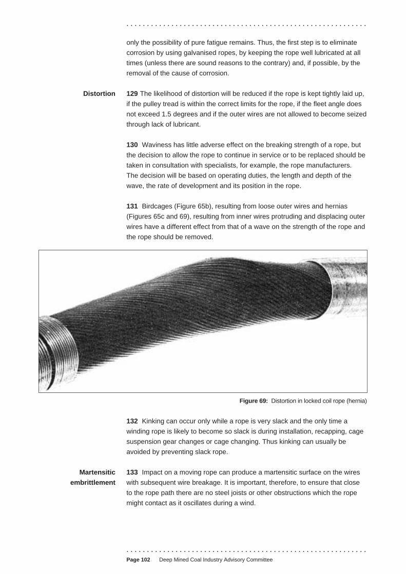
. . . . . . . . . . . . . . . . . . . . . . . . . . . . . . . . . . . . . . . . . . . . . . . . . . . . . . . . . . .
only the possibility of pure fatigue remains. Thus, the first step is to eliminate
corrosion by using galvanised ropes, by keeping the rope well lubricated at all
times (unless there are sound reasons to the contrary) and, if possible, by the
removal of the cause of corrosion.
Distortion 129 The likelihood of distortion will be reduced if the rope is kept tightly laid up,
if the pulley tread is within the correct limits for the rope, if the fleet angle does
not exceed 1.5 degrees and if the outer wires are not allowed to become seized
through lack of lubricant.
130 Waviness has little adverse effect on the breaking strength of a rope, but
the decision to allow the rope to continue in service or to be replaced should be
taken in consultation with specialists, for example, the rope manufacturers.
The decision will be based on operating duties, the length and depth of the
wave, the rate of development and its position in the rope.
131 Birdcages (Figure 65b), resulting from loose outer wires and hernias
(Figures 65c and 69), resulting from inner wires protruding and displacing outer
wires have a different effect from that of a wave on the strength of the rope and
the rope should be removed.
Martensitic
embrittlement
Figure 69: Distortion in locked coil rope (hernia)
132 Kinking can occur only while a rope is very slack and the only time a
winding rope is likely to become so slack is during installation, recapping, cage
suspension gear changes or cage changing. Thus kinking can usually be
avoided by preventing slack rope.
133 Impact on a moving rope can produce a martensitic surface on the wires
with subsequent wire breakage. It is important, therefore, to ensure that close
to the rope path there are no steel joists or other obstructions which the rope
might contact as it oscillates during a wind.
. . . . . . . . . . . . . . . . . . . . . . . . . . . . . . . . . . . . . . . . . . . . . . . . . . . . . . . . . . .Page 102 Deep Mined Coal Industry Advisory Committee
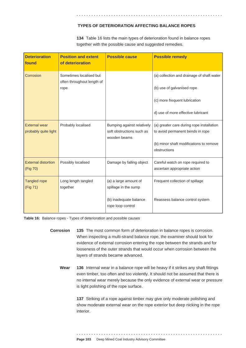
. . . . . . . . . . . . . . . . . . . . . . . . . . . . . . . . . . . . . . . . . . . . . . . . . . . . . . . . . . .
TYPES OF DETERIORATION AFFECTING BALANCE ROPES
134 Table 16 lists the main types of deterioration found in balance ropes
together with the possible cause and suggested remedies.
Deterioration Position and extent Possible cause Possible remedy
found of deterioration
Corrosion Sometimes localised but (a) collection and drainage of shaft water
often throughout length of
rope (b) use of galvanised rope
(c) more frequent lubrication
d) use of more effective lubricant
External wear Probably localised Bumping against relatively (a) greater care during rope installation
probably quite light soft obstructions such as to avoid permanent bends in rope
wooden beams
(b) minor shaft modifications to remove
obstructions
External distortion Possibly localised Damage by falling object Careful watch on rope required to
(Fig 70) ascertain appropriate action
Tangled rope Long length tangled (a) a large amount of Frequent collection of spillage
(Fig 71) together spillage in the sump
(b) inadequate balance Reassess balance control system
rope loop control
Table 16: Balance ropes - Types of deterioration and possible causes
Corrosion 135 The most common form of deterioration in balance ropes is corrosion.
When inspecting a multi-strand balance rope, the examiner should look for
evidence of external corrosion entering the rope between the strands and for
looseness of the outer strands that would occur when corrosion between the
layers of strands became advanced.
Wear 136 Internal wear in a balance rope will be heavy if it strikes any shaft fittings
even timber, too often and too violently. It should not be assumed that there is
no internal wear merely because the only evidence of external wear or pressure
is light polishing of the rope surface.
137 Striking of a rope against timber may give only moderate polishing and
show moderate external wear on the rope exterior but deep nicking in the rope
interior.
. . . . . . . . . . . . . . . . . . . . . . . . . . . . . . . . . . . . . . . . . . . . . . . . . . . . . . . . . . .
.Page 103 Deep Mined Coal Industry Advisory Committee
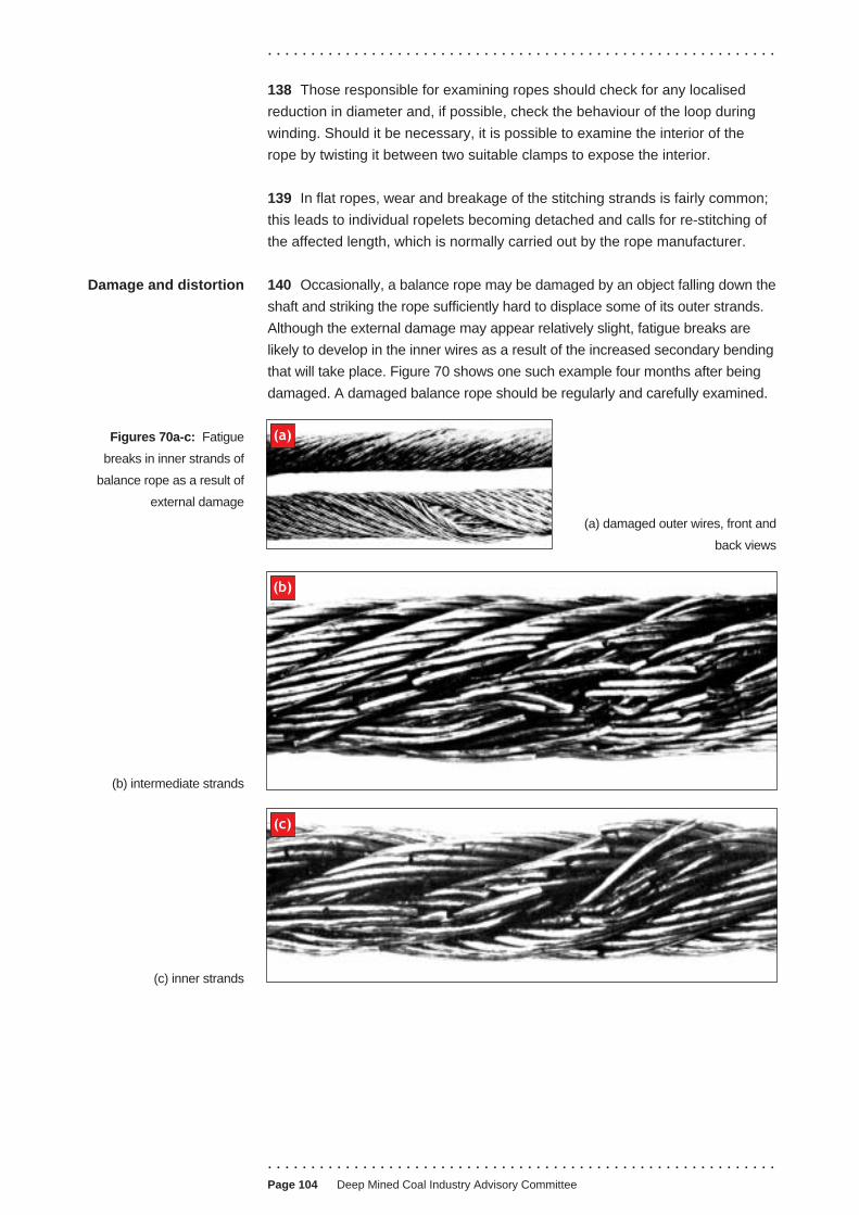
Damage and distortion
Figures 70a-c: Fatigue
breaks in inner strands of
balance rope as a result of
external damage
(b) intermediate strands
(c) inner strands
. . . . . . . . . . . . . . . . . . . . . . . . . . . . . . . . . . . . . . . . . . . . . . . . . . . . . . . . . . .
138 Those responsible for examining ropes should check for any localised
reduction in diameter and, if possible, check the behaviour of the loop during
winding. Should it be necessary, it is possible to examine the interior of the
rope by twisting it between two suitable clamps to expose the interior.
139 In flat ropes, wear and breakage of the stitching strands is fairly common;
this leads to individual ropelets becoming detached and calls for re-stitching of
the affected length, which is normally carried out by the rope manufacturer.
140 Occasionally, a balance rope may be damaged by an object falling down the
shaft and striking the rope sufficiently hard to displace some of its outer strands.
Although the external damage may appear relatively slight, fatigue breaks are
likely to develop in the inner wires as a result of the increased secondary bending
that will take place. Figure 70 shows one such example four months after being
damaged. A damaged balance rope should be regularly and carefully examined.
(a)
(a) damaged outer wires, front and
back views
(b)
(c)
. . . . . . . . . . . . . . . . . . . . . . . . . . . . . . . . . . . . . . . . . . . . . . . . . . . . . . . . . . . Page 104 Deep Mined Coal Industry Advisory Committee

. . . . . . . . . . . . . . . . . . . . . . . . . . . . . . . . . . . . . . . . . . . . . . . . . . . . . . . . . . .
141 If spillage in the sump is allowed to build up to
reach the balance rope, the loop will become
displaced; it may then become entangled (Figure
71), and fail under holdfast conditions. Methods of
controlling spillage and of monitoring any unusual
rise in the balance rope loop have been discussed
earlier in this chapter.
When to discard a 142 The part most likely to be weakened by
balance rope deterioration is the lengths of rope that form the
loop when one or other of the conveyances is at
pit bottom. The rope is more likely to break when
one of the conveyances is near the top of the
shaft, when the most weakened part of the rope
has to support the greatest length of rope.
143 Should the balance rope break under these Figure 71: Knotted balance
circumstances it would fall on the lower cage, and at rope, the result of spillage in
the same time throw the winding system out of the sump
balance increasing the likelihood of either an over
wind on a drum winder, or rope slippage on the driving sheave of a friction-
winder.
144 ACOP 129 of the 1993 Regulations3 requires that balance rope life should
not exceed five years on drum winders and three years on friction winders
unless other directions have been given by an HSE inspector.
TYPES OF DETERIORATION AFFECTING GUIDE AND RUBBING ROPES
Wear 145 Table 17 lists the main types of deterioration affecting guide and rubbing
ropes together with the possible cause and suggested remedies.
146 One-sided wear affects all the wires because of the rope construction
(Figure 72), rapidly reducing rope strength. The use of brass or phosphor-
bronze cage shoes helps to minimise such wear and rotating the rope at
intervals helps to equalise it round the rope circumference.
147 Where sleeves are fitted to guide ropes in the sump, localised wear may
occur. It is critical that the sleeves should be removed at intervals depending on
shaft conditions to examine the rope and re-pack with lubricant (Figure 73).
Figure 72: Half-locked
guide rope, showing one- 148 Appendix 7 shows a chart that gives the reduction in effective cross-
sided wear sectional area of a guide rope for both even and uneven wear.
Corrosion 149 If corrosion (Figure 74) throughout the length of the rope is a problem
more frequent lubrication or a different type of lubricant may cure the trouble.
Any shaft water, even if not particularly corrosive, should be diverted away from
. . . . . . . . . . . . . . . . . . . . . . . . . . . . . . . . . . . . . . . . . . . . . . . . . . . . . . . . . . .
.Page 105 Deep Mined Coal Industry Advisory Committee

. . . . . . . . . . . . . . . . . . . . . . . . . . . . . . . . . . . . . . . . . . . . . . . . . . . . . . . . . . .
Deterioration
found
Position and extent
of deterioration
Possible cause Possible remedy
Wear (i) along one side of rope
(Fig 72)
Lateral force on
conveyance
Ropes should be given a quarter turn at
intervals to spread the wear evenly
(ii) localised (a) permanent bend, or Greater care during installation
(b) opposite fan drift, at
insets, at point of entry or
exit from receivers, at
sump timbers
Lift rope at intervals to change position
of increased wear
(c) immediately below
headgear capping
(between supports)
Correct positioning of termination
Corrosion (Fig 74) (i) throughout length of
rope
Lack of sufficient
lubrication, use of
unsuitable lubricant, or
water in the shaft
More frequent lubrication, divert water
away from ropes, use lubricant with
water-displacing additives
(ii) localised Possibly in confined space,
eg where passing through
hole in sump boards
Fit sleeve well packed with grease
(Fig 73)
When to discard a
guide or rubbing rope
Table 17: Guide and rubbing ropes - Types of deterioration and possible causes
the ropes. Close scrutiny should always be kept for localised corrosion, even on
ropes which are otherwise little affected by it.
150 Localised corrosion may occur in confined spaces such as the holes
where the rope passes through the sump boards or at parts where the lubricant
is dried by the effect of shaft heaters and more frequent lubrication should be
given to these parts.
151 As with other ropes, a guide or rubbing rope should be discarded when the
outer wires have lost one-third (about 33%) of their depth by wear or corrosion
or both, or when the rope appears to be no longer in a safe condition for any
reason such as the appearance of broken wires. There is no legal or statutory
limit to the length of life for guide ropes and rubbing ropes. It is unusual for a
rope to remain in service for more than 20 years, and many shafts ropes need
replacing much earlier in their lives. ACOP paragraphs 202 and 203 of the 1993
Regulations3 provide further advice on this matter.
. . . . . . . . . . . . . . . . . . . . . . . . . . . . . . . . . . . . . . . . . . . . . . . . . . . . . . . . . . . Page 106 Deep Mined Coal Industry Advisory Committee
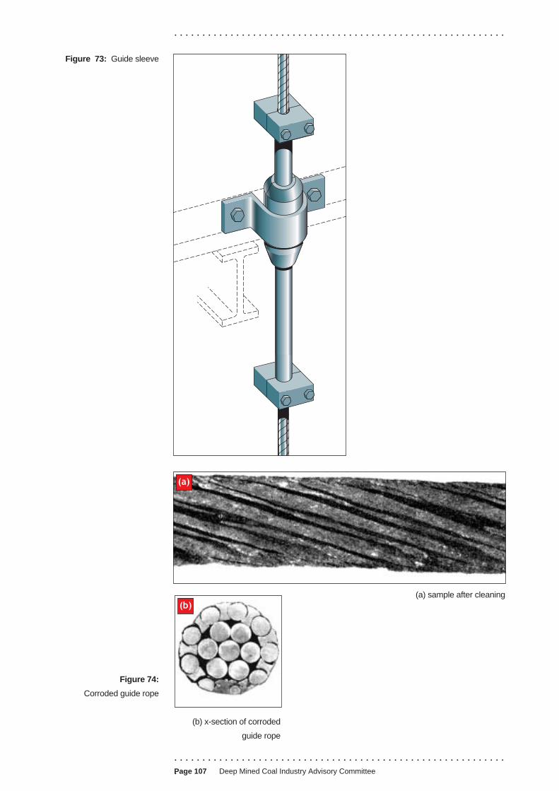
. . . . . . . . . . . . . . . . . . . . . . . . . . . . . . . . . . . . . . . . . . . . . . . . . . . . . . . . . . .
Figure 73: Guide sleeve
(a)
(b) (a) sample after cleaning
Figure 74:
Corroded guide rope
(b) x-section of corroded
guide rope
. . . . . . . . . . . . . . . . . . . . . . . . . . . . . . . . . . . . . . . . . . . . . . . . . . . . . . . . . . .
.Page 107 Deep Mined Coal Industry Advisory Committee

. . . . . . . . . . . . . . . . . . . . . . . . . . . . . . . . . . . . . . . . . . . . . . . . . . . . . . . . . . .
APPENDIX 1
REPORT ON THE CAPPING OF SHAFT ROPES USING RESIN
. . . . . . . . . . . . . . . . . . . . . . . . . . . . . . . . . . . . . . . . . . . . . . . . . . . . . . . . . . . Page 108 Deep Mined Coal Industry Advisory Committee

. . . . . . . . . . . . . . . . . . . . . . . . . . . . . . . . . . . . . . . . . . . . . . . . . . . . . . . . . . .
. . . . . . . . . . . . . . . . . . . . . . . . . . . . . . . . . . . . . . . . . . . . . . . . . . . . . . . . . . .
.Page 109 Deep Mined Coal Industry Advisory Committee
Report on the capping of shaft ropes using resin
Date of capping/s. ....................................................
Tick as appropriate
Pre-capped rope Rope reel No. and Order No. .....................................................................
Capped at mine Location and identification of rope including Order No. .............................................................................
Resin kit size 500 cc Batch number. ................................................................................................ 1000 cc Expiry date. ....................................................................................................
1700 cc Number of capping from each kit. .............................................................
3400 cc
Ambient temperature ....................oC Socket temperature .......................oC
Booster pack Yes If yes, state: No. of booster packs used ...................................................... No Batch number ............................................................................
Expiry date ................................................................................
Preheated socket Yes If yes, state temperature of socket bore after pre-heating ..........................oC No
Gel time* ................minutes
Comments ................................................................................................................................................................................................................................................................................................................................................................................................................................................................................................................................................................................................................................................................................................................................................
Signature of competent person ......................................................... Date .......................................................... who has made the capping
Company .................................................................................................................
Signature of person appointed to supervise the capping ......................................................... Date ...............................................................
Signature of mechanical engineer ......................................................... Date ...............................................................
Signature of Manager or person nominated by him to sign the report on his behalf ......................................................... Date ...............................................................

. . . . . . . . . . . . . . . . . . . . . . . . . . . . . . . . . . . . . . . . . . . . . . . . . . . . . . . . . . .
APPENDIX 2
REPORT ON PERIODIC EXAMINATION OF WINDING ROPES AND
BALANCE ROPES
. . . . . . . . . . . . . . . . . . . . . . . . . . . . . . . . . . . . . . . . . . . . . . . . . . . . . . . . . . . Page 110 Deep Mined Coal Industry Advisory Committee

. . . . . . . . . . . . . . . . . . . . . . . . . . . . . . . . . . . . . . . . . . . . . . . . . . . . . . . . . . .
. . . . . . . . . . . . . . . . . . . . . . . . . . . . . . . . . . . . . . . . . . . . . . . . . . . . . . . . . . .
.Page 111 Deep Mined Coal Industry Advisory Committee
Report on periodic examination of winding ropes and balance ropes
Shaft and identification of rope including manufacturer's Test Certificate number
Length of rope (metres) Nominal dia. (mm) Date installed Date of examination
Place examined
(a) Places particularly liable to deterioration:
(b) Other places not more than 90 metres apart:
Signature of appointed person who has made the examination ......................................................... Date ...............................................................
Signature of mine mechanical engineer ......................................................... Date ...............................................................
Signature of Manager or person nominated by him to sign the report on his behalf ......................................................... Date ...............................................................

. . . . . . . . . . . . . . . . . . . . . . . . . . . . . . . . . . . . . . . . . . . . . . . . . . . . . . . . . . .
APPENDIX 3
REPORT OF INTERNAL EXAMINATION OF LENGTH OF WINDING ROPE
CUT OFF DURING RECAPPING
. . . . . . . . . . . . . . . . . . . . . . . . . . . . . . . . . . . . . . . . . . . . . . . . . . . . . . . . . . . Page 112 Deep Mined Coal Industry Advisory Committee

. . . . . . . . . . . . . . . . . . . . . . . . . . . . . . . . . . . . . . . . . . . . . . . . . . . . . . . . . . .
. . . . . . . . . . . . . . . . . . . . . . . . . . . . . . . . . . . . . . . . . . . . . . . . . . . . . . . . . . .
.Page 113 Deep Mined Coal Industry Advisory Committee
Report of internal examination of length of winding rope cut off during recapping
Location and identification of rope including manufacturer's Test Certificate No. .......................................................
Length of rope ............................metres Date installed ............................................................................................
Date of: previous capping/re-capping ..................................................... Length ofthis capping ..................................................................... rope cut off ...............................metres
Report of examination on (date) .................................................. of internal condition of length of rope
Signature of appointed person who has made the examination ......................................................... Date ..........................................................
Signature of mine mechanical engineer ......................................................... Date ..........................................................
Signature of Manager or person nominated by him to sign the report on his behalf ......................................................... Date ..........................................................

. . . . . . . . . . . . . . . . . . . . . . . . . . . . . . . . . . . . . . . . . . . . . . . . . . . . . . . . . . .
APPENDIX 4
SAMPLE OF A REPORT OF THE THOROUGH EXAMINATION AND
TESTING OF A ROPE SAMPLE
. . . . . . . . . . . . . . . . . . . . . . . . . . . . . . . . . . . . . . . . . . . . . . . . . . . . . . . . . . . Page 114 Deep Mined Coal Industry Advisory Committee

. . . . . . . . . . . . . . . . . . . . . . . . . . . . . . . . . . . . . . . . . . . . . . . . . . . . . . . . . . .
. . . . . . . . . . . . . . . . . . . . . . . . . . . . . . . . . . . . . . . . . . . . . . . . . . . . . . . . . . .
.Page 115 Deep Mined Coal Industry Advisory Committee
Sample of a report of the thorough examination and testing of a rope sample
Mine .......................................................................................... Winding rope / Haulage rope / Guide rope .......................................................................................... (Strike out where not app licab le) ..........................................................................................
Makers ................................................................................
Shaft number .............................................................................. Test Cert. No. ........................... Order No. ...............
Location ..................................................................................... Date ....................................................................................
Specification of rope
Length ................................................. m Diameter .................................... mm Weight per 100 m .....
Type ......................................................... Pitch of lay .................................. mm Direction of lay ...........
Location ..................................................................................... Wire finish ..................................................................
Particulars of rope sample
Date when sample was cut off .................................................. Last previous capping .............................................
Length cut off ...................................................................... mm Date put to use .......................................................
.
Length of sample received ................................................................................... mm Measured diameter ......... mm
Length tested for torsion, etc ............................................................................... mm Measured diameter .......... mm
Number of broken wires found in tested length (if any) ....................................................................................................
Number of broken wires found in remainder of sample .....................................................................................................
Internal condition of sample, in particular lubrication ..........................................................................................................
Remarks, in particular surface condition of wires .................................................................................................................
.......................................................................................................................................................................................................
Position & description of wires
Direction of lay
Construction Diameter of wire
Number of wires
(N) Number of wires tested
Max Min Average
Torsions in 100 diameters
Number of wires tested
Max
Bends 180o
Radius (mm)
Min Average Number of wires tested
TOTAL NxW in Kg
Tensiles Breaking load in Kg
Max Min Average (W)
Sum of items (N x W) Kg
Aggregate breaking load Sum of items (N x W) tonnes
Sum of items (N x W) Kg

. . . . . . . . . . . . . . . . . . . . . . . . . . . . . . . . . . . . . . . . . . . . . . . . . . . . . . . . . . .
Test number ..........................................
Specified actual BL ................... tonnes ...................... kg Specified aggregate SL ................... tonnes ...................... kg
Last previous test number ........................................... on .................................................. gave aggregate BL .............. tonnes
First test on new rope number .................................... on .................................................. gave aggregate BL .............. tonnes
Aggregate BL (less broken wires) .......................... tonnes Act BL = aggregate less .............. % .............. tonnes
Static load (with ............ tonnes coal) ............................................. tonnes F of S on Act BL ............................................
Static load (with ............ tonnes dirt) .............................................. tonnes F of S on Act BL ............................................
Static load (with ............ men of 75 Kg each) ................................. tonnes F of S on Act BL ............................................
Static load(s) consist(s) of Tonnes Kg
Suspended winding rope .......................................................... = ..........................................................
Suspension gear .......................................................... = ..........................................................
Cage/skip .......................................................... = ..........................................................
................................................... .......................................................... = ..........................................................
........................................... coal .......................................................... = ..........................................................
............................................ dirt .......................................................... = ..........................................................
........................................... men .......................................................... = .........................................................
Suspended balance rope .......................................................... = .........................................................
Special notes
Test carried out by ............................................................. Date sample received .................................................................
Countersigned ................................................................... Date sample tested .....................................................................
Special notes
. . . . . . . . . . . . . . . . . . . . . . . . . . . . . . . . . . . . . . . . . . . . . . . . . . . . . . . . . . . Page 116 Deep Mined Coal Industry Advisory Committee
. . . . . . . . . . . . . . . . . . . . . . . . . . . . . . . . . . . . . . . . . . . . . . . . . . . . . . . . . . .
APPENDIX 5
REPORT OF PERIODIC EXAMINATION OF GUIDE AND RUBBING ROPES
. . . . . . . . . . . . . . . . . . . . . . . . . . . . . . . . . . . . . . . . . . . . . . . . . . . . . . . . . . .
.Page 117 Deep Mined Coal Industry Advisory Committee

Rope details
Date installed ....................................................................
Type Rubbing guide*
Nominal diameter .............................................................
Manufacturer ....................................................................
Nominal breaking load ....................................................
Construction .....................................................................
. .........................................................................................
. .........................................................................................
Length of rope ................................................................
Weight of rope (Kg/100 m ) ........................................
Date last lifted .................................................................
Date last turned ..............................................................
Applied tension .................................................. tonnes
Method of tensioning* ...................................................
Weights Surface
Springs Underground
Mine ..................................................... Shaft ......................................................
Rope Test Certificate number .............................................................................. Report number .................................... Date of inspection ..............................
Condition of sump In sump (a) clear of water
(b) clear of debris
Sig pers s
* Del licab le
Rope assessment No. Dated:
Nominal factor of safety (at headgear clamp)
Minimum factor of safety
Position of min F of S
Condition of rope at point of inspection with particular reference to even or uneven wear, lubrication,
corrosion, pitting or any observed defect
Position of inspection
Headframe capping
Banking level
Entrance to surface receivers
Fan drift
Intermed Revs below positions bank level
Pit bttm inset
Sump platform
Distance below banking level
(m)
Rope diameter MIN (mm)
MAX (mm)
..........................................................................................Examiner: Date
Running off (surface) or skip discharge side
Report of periodic examination of guide and rubbing rope
Signature of Mine Mech Engineer:................................................................................................ Date..................................
Signature of Mine Manager:........................................................................................................... Date..................................
Minimum measured diameter
nature of appointed on who ha made the examination
ete where not app
Fill in from rope assessment sheet

Guide and rubbing rope inspection assessment
Mine ............................................................................................................ Shaft .........................................................
Assessment number .................................................................
Assessment number .................................................................
Based on Inspection Report number ...................................................................................................................................
for inspection dated .............................................................................................................................................................
Total maximum tension at Headframe ...................................................................................................................... tonnes
Method of tensioning:
Weights Surface
Springs Underground
(Delete words not applicable)
Nominal breaking load .........................................................................................................................................................
Nominal factor of safety .......................................................................................................................................................
Position of minimum factor of safety ...................................................................................................................................
Tension at this point .............................................................................................................................................................
Estimated breaking load .......................................................................................................................................................
Minimum factor of safety .....................................................................................................................................................
Remarks ................................................................................................................................................................................................................................................................................................................................................................................................................................................................................................................................................................................................................................................................................................................................................................................................................................................................................................................................................................................................................................................................................................................................................................................................................................................................................................................................................................................................................................................................................................................................................................................................................................................................................................................................................................................................................................................................................................................................................................................................................................................................................................................................................................................................................................................................................................................................................................................
Signed ........................................................................... Designation .............................................................................
Distribution:
. . . . . . . . . . . . . . . . . . . . . . . . . . . . . . . . . . . . . . . . . . . . . . . . . . . . . . . . . . .
APPENDIX 6
PROCEDURE FOR THE NON-DESTRUCTIVE TESTING (NDT) OF LOCKED
COIL ROPES (Can also be used, as appropriate, as a guide for the NDT of
other types of rope)
General requirements 1 Only suitably trained people authorised by the mine manager should
undertake the NDT of wire ropes.
2 Those carrying out the operation should follow managers’ rules for such work.
3 The mine mechanical engineer should ensure that a competent person:
(a) carries out a risk assessment and produces a method statement covering
the NDT operation and associated activities, including access to temporary
workplaces;
(b) supervises the safe completion of the NDT operation and associated
activities;
(c) ensures that only authorised winding engine drivers operate the winding
apparatus during testing;
(d) ensures that any guards, covers, etc, that have been removed to allow
NDT to take place, are replaced;
(e) ensures that safety harnesses are provided and worn by all persons at risk
of falling from height;
(f) ensures the availability at all times of adequate communications between
the NDT operatives, the winding engine operator, and, where appropriate,
the banksman and onsetter.
Other precautions 4 NDT equipment in contact with the rope must be securely anchored to
prevent the equipment moving excessively.
5 People must stand clear of the winding apparatus, eg headgear pulleys,
while it is moving.
6 People must handle all substances that are potentially hazardous to health
in accordance with the instructions for their safe use, provided in accordance
with the requirements of the COSHH Regulations.10
Training 7 Adequate training and experience for NDT operatives is that which meets
the requirements of prEN 12927-8 - Safety requirements for passenger
transportation by rope - Part 8: Non-destructive testing.
. . . . . . . . . . . . . . . . . . . . . . . . . . . . . . . . . . . . . . . . . . . . . . . . . . . . . . . . . . . Page 120 Deep Mined Coal Industry Advisory Committee

. . . . . . . . . . . . . . . . . . . . . . . . . . . . . . . . . . . . . . . . . . . . . . . . . . . . . . . . . . .
8 The operator should have sufficient technical knowledge to understand how
the NDT method works, and appreciate the implications and importance of NDT
as an aid to visual inspection and the condition monitoring of winding ropes.
9 All NDT operators should be able to read the Jaeger J2 eye chart at a
distance of 0.5 m, with the aid of spectacles if necessary.
Principle of operation 10 A test head containing permanent magnets, local faults (LF), cross
sectional area (CSA) sensors and a distance measuring device is positioned
around the rope. Data is transferred from the test head to an electronics signal
processor. The processed signals are then sent to a recorder that meets the
requirements of prEN 12927 - 8. It should incorporate an instantaneous visual
output for on-the-spot analysis of the condition of the rope, and to aid any
necessary visual re-examination.
11 All new NDT equipment should be subjected to an overall performance test
on the locked coil test ropes at the Health and Safety Laboratory of the Health
and Safety Executive.
Positioning of test
head
12 The position of the test head at the start of the test should be selected to
ensure the testing of the maximum length of rope possible. Its location will
depend upon the type of installation, the accessibility of the rope, and the
positioning of landings or platforms etc.
Drum winding systems 13 To ensure maximum coverage of the rope, the test head should be placed
beneath the headgear pulley but above the detaching bell or catch plate. This
will also ensure the testing of the rope’s acceleration zone, ie the portion of the
rope which passes over the headgear pulleys or onto the drum during the
acceleration period of an ascending wind.
14 If the rope between the capping and the bell or catch plate is to be tested,
the method statement should include the provision of suitable platforms to allow
for safe access to the rope.
15 It is not normally practicable to test the length of rope between the drum
and the headgear while the cage/skip is approaching the bottom of the shaft.
Lateral and vertical motion of the rope at a test position close to the drum can
make the test difficult to carry out.
Friction winding
systems
16 The test head should be placed on the rope at a position as close as
practicable to the conveyance or counterweight suspension point. To test the
portion of the rope lying on the winding sheave, which cannot be tested from this
position, the test head will need to be placed on the opposite side of the sheave.
Test procedure 17 In order to accurately determine the rope signature (benchmark) a new
rope should be NDT’d as soon as possible following installation.
. . . . . . . . . . . . . . . . . . . . . . . . . . . . . . . . . . . . . . . . . . . . . . . . . . . . . . . . . . .
.Page 121 Deep Mined Coal Industry Advisory Committee

. . . . . . . . . . . . . . . . . . . . . . . . . . . . . . . . . . . . . . . . . . . . . . . . . . . . . . . . . . .
General procedure
18 Before commencing the test establish that adequate communication
facilities exist with the winding engineman, and that it is safe to approach the
rope. All the signals and instructions to the winding engineman must be clear
and unambiguous. Ensure that the rope to be tested is in the fully wound
condition, ie with one of the conveyances at the surface.
19 Ensure that the internal diameter of the test head rope guide is such as to
enable the rope to pass freely through the test head. Any adjustments required
must be made at this stage.
20 Position the test head around the rope and ensure that the head is
securely anchored to the structure in order to prevent excessive movement of
the head.
21 After making all electrical connections, check that the distance indicator,
LF and CSA channels are operating correctly. Carry out a simple function test
by inserting a length of small diameter (eg 5 mm) wire into the test head
between the rope and the sensors and observe the response on the LF and
CSA channels as the wire is moved through the test head. If there is no
response then check the equipment connections and repeat the test. The
absence of any response indicates a fault in the test equipment.
Test sensitivity
22 Adjust the LF test sensitivity to give an indicated rope signature of typical
amplitude between 5% and 10% of the full width of the on-site display unit.
23 Adjust CSA test sensitivity to give a drift of not more than 10% nominal at a
background noise level of approximately 2% of the full width of the on-site
display unit.
24 The overall test sensitivity should comply with the requirements of
prEN 12927-8.
Rope speed and direction
25 The rope should pass through the test head at a uniform speed. The speed
at which the rope can be tested will vary depending upon the type of installation
and the response of the test equipment used, but should not exceed 2.5 m/s.
26 Testing should normally be carried out with the rope travelling in a
downwards direction through the test head. If the direction of rope travel is
reversed, the rope should run at no more than the slowest speed or ‘creep
speed’ unless the test head is removed from the rope prior to rewinding.
. . . . . . . . . . . . . . . . . . . . . . . . . . . . . . . . . . . . . . . . . . . . . . . . . . . . . . . . . . . Page 122 Deep Mined Coal Industry Advisory Committee
. . . . . . . . . . . . . . . . . . . . . . . . . . . . . . . . . . . . . . . . . . . . . . . . . . . . . . . . . . .
Distance of travel indication
27 Equipment conforming to the requirements of prEN 12927-8 will produce an
indication for every 1 m of rope travel. It is often useful to have additional ‘bench
marks’ which may be obtained from the conveyance position monitoring system.
Visual observations
28 Anomalies observed on the visual display, in particular LF indications
which could possibly have arisen from external wire breaks should be
investigated immediately. The suspect region of the rope should be thoroughly
cleaned and subjected to a close visual examination. A record should be made
of the position of any significant LF indication along the length of the rope and
of the result of the visual inspection of the rope at those points.
Test precautions 29 The test head and rope should be closely supervised during testing to ensure:
(a) that the test head remains securely anchored and firmly positioned around
the rope. If it moves excessively the test should be stopped and the test
head repositioned;
(b) free movement of the rope through the test head.
30 Magnetic rope striping, where a series of uniformly spaced magnetic
imprints are induced in the rope, is sometimes used as a means for the
determination of the position of a conveyance within a shaft. The NDT
operation can erase or corrupt the magnetic stripes in such ropes and therefore
it is essential to ascertain whether the rope has been magnetically striped.
Method of reporting 31 The test supervisor should notify the mine mechanical engineer or a
person nominated by the engineer of the test results before the test supervisor
leaves the site. This will enable an appropriate decision to be made regarding
any remedial action that may be necessary.
32 The test supervisor should submit an adequate written report as soon as
practicable after carrying out the test. The report should include the following
details:
(a) identity of the NDT personnel and the employer;
(b) the date of the test;
(c) the date of any previous test;
(d) the site and installation tested;
(e) identification of the ropes tested;
. . . . . . . . . . . . . . . . . . . . . . . . . . . . . . . . . . . . . . . . . . . . . . . . . . . . . . . . . . .
.Page 123 Deep Mined Coal Industry Advisory Committee

. . . . . . . . . . . . . . . . . . . . . . . . . . . . . . . . . . . . . . . . . . . . . . . . . . . . . . . . . . .
(f) rope details (ie date put to use, manufacturer, diameter, construction etc.);
(g) type and make of test equipment used;
(h) test positions;
(i) identification of the length or region of the rope actually tested;
(j) approximate rope speed at which testing was carried out;
(k) any additional tests carried out.
33 An adequate report will identify the position, type and extent of any
significant indications or observations. It should compare with previous test
results, any increase in the size, number or extent of the indications or
observations, and include a summary of the results and conclusions.
34 A record of all tests carried out together with details of the test equipment
settings should be retained by the NDT operator and made available for the
mine manager as necessary.
Interpretation of 35 It is not possible to provide a definitive guide to the interpretation of the test
results results due to the variability between test equipment, difference in the method
of display, physical differences between ropes etc. As a consequence it is
important that the NDT personnel are familiar with the history of previous ropes
on the same installation since this will provide valuable information which can
be used as an aid to interpretation, and will supplement the skills and
experience of such personnel.
36 Interpretation should be carried out in two stages. First, note the nature of
all recorded LF indications and calculate their positions in the rope. The LF
indications normally arise either as a consequence of an apparent increase in
the rope cross section or an apparent decrease in cross section. The nature of
the LF indications will allow apparent defects to be categorised. The CSA
channel should be analysed in conjunction with the LF channel.
37 Secondly, carry out a more detailed analysis of the LF indications in order
to identify wire break indications, particularly external wire break indications,
and other factors which may give rise to a recordable indication.
38 Wherever possible the test results shall be correlated with previous test
results on the same rope, and on the previous rope at a similar stage in its
service life.
39 Further guidance may be obtained from HSL research report NoFE/02/07,
entitled Evaluation of instruments for non-destructive testing of wire ropes.
. . . . . . . . . . . . . . . . . . . . . . . . . . . . . . . . . . . . . . . . . . . . . . . . . . . . . . . . . . . Page 124 Deep Mined Coal Industry Advisory Committee

. . . . . . . . . . . . . . . . . . . . . . . . . . . . . . . . . . . . . . . . . . . . . . . . . . . . . . . . . . .
APPENDIX 7
REDUCTION IN EFFECTIVE AREA DUE TO WEAR ON HALF LOCK GUIDE
ROPES
. . . . . . . . . . . . . . . . . . . . . . . . . . . . . . . . . . . . . . . . . . . . . . . . . . . . . . . . . . .
.Page 125 Deep Mined Coal Industry Advisory Committee
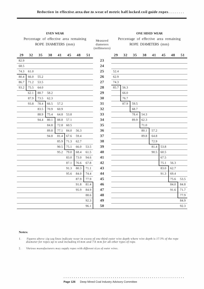
Reduction in effective area due to wear of metric half locked coil guide ropes . . . . . . . . . . . . . . . . . . . . . . . . . . . . . . . . . . . . . . . . . . . . . . . . . . . . . . . . . . .
EVEN WEAR ONE SIDED WEAR
Percentage of effective area remaining Measured Percentage of effective area remaining
ROPE DIAMETERS (mm) diameters ROPE DIAMETERS (mm) (millimeters)
29 32 35 38 41 45 48 51 29 32 35 38 41 45 48 51
82.9 23
68.5 24
74.3 61.0 25 52.4
80.4 66.0 55.2 26 62.9
86.7 71.2 53.5 27 74.3
93.2 75.5 64.0 28 85.7 56.3
62.1 88.7 58.2 29 66.0
87.9 73.5 62.3 30 76.7
93.8 78.4 66.5 57.2 31 87.9 59.5
83.5 70.9 60.9 32 68.7
88.9 75.4 64.8 53.8 33 78.4 54.3
94.4 80.1 88.8 57.1 34 89.9 62.3
84.8 72.8 60.5 35 71.0
89.8 77.1 84.0 56.3 36 80.1 57.2
94.8 81.4 67.6 59.4 37 89.8 64.8
85.9 71.3 62.7 38 72.9
90.5 75.1 66.0 53.5 39 81.4 53.8
95.2 79.0 68.4 61.5 40 90.5 60.5
83.0 73.0 94.6 41 67.5
87.1 76.6 67.8 42 75.1 56.3
91.3 80.3 71.1 43 83.0 62.7
95.6 84.0 74.4 44 91.3 69.4
87.9 77.9 45 75.6 53.5
91.8 81.4 46 84.0 84.8
95.9 84.9 47 91.6 71.7
88.6 48 77.9
92.3 49 84.9
96.1 50 92.3
. . . . . . . . . . . . . . . . . . . . . . . . . . . . . . . . . . . . . . . . . . . . . . . . . . . . . . . . . . . Page 126 Deep Mined Coal Industry Advisory Committee
. . . . . . . . . . . . . . . . . . . . . . . . . . . . . . . . . . . . . . . . . . . . . . . . . . . . . . . . . . .
APPENDIX 8
ROPES ON LIFTS IN MINE SHAFTS
1 Where a lift is installed in a mine shaft, then the design, operation and
maintenance of the installation should comply with the relevant sections of the
Regulations and ACOP3 and appropriate standards for lift practice.
2 To assist mine management in the operation and maintenance of a lift
system, the following publications and guidance should be readily available to
the management for consultation and use as necessary:
■ BS EN 12385-5:2002 Steel wire ropes. Safety. Stranded ropes for lifts;21
■ Health and Safety Executive Guidance Note PM7 - Lifts: thorough
examination and testing;22
■ OTIS - Field Engineering Instruction:PM7 Examination and testing;23
■ Bridon Ropes publication - Ropes for lifts;24
■ BS 2655 : Part 1 : 1970 : Specification for lifts, escalators, passenger
conveyors and paternosters : Part 1 - General requirements for electric,
hydraulic and hand-powered lifts;25
■ BS 5655 - Lifts and service lifts - Safety rules for the construction and
installation of electric lifts.26
3 The above documents provide good advice on the application and
maintenance of suspension, compensating, governor and tail/balance ropes on
lifts. It is important to emphasise that due to operating conditions in shafts all
the ropes on a lift installation need to be examined critically and thoroughly to
determine indications of deterioration.
. . . . . . . . . . . . . . . . . . . . . . . . . . . . . . . . . . . . . . . . . . . . . . . . . . . . . . . . . . .
.Page 127 Deep Mined Coal Industry Advisory Committee

. . . . . . . . . . . . . . . . . . . . . . . . . . . . . . . . . . . . . . . . . . . . . . . . . . . . . . . . . . .
REFERENCES AND FURTHER READING
References 1 Guidance on the selection, installation, maintenance and use of steel wire
haulage ropes at mines HSE Books 2004 ISBN 0 7176 2680 6
2 Mines (Shafts and Winding) Regulations 1993 SI 1993/302 The Stationery
Office ISBN 0 11 033302 0
3 Shafts and winding in mines. Mines (Shafts and Winding) Regulations
1993. Approved Code of Practice L42 HSE Books 2000 ISBN 0 11 882164 4
4 Management and Administration of Safety and Health at Mines
Regulations 1993 SI 1993/1897 The Stationery Office ISBN 0 11 034897 4
5 Steel wire ropes. Safety. General requirements BS EN 12385-1:2002
British Standards Institute
6 Stranded steel wire ropes. Specification for ropes for mine hoisting
BS 302-6:1987 British Standards Institute
7 NCB Specification No 186: 1970 Out of print
8 NCB Specification No 388/1970 Out of print
9 Safe manriding in mines report - available from HMSO Parts 1A and 1B
ISBN 0 11 880491 X, Parts 2A and 2B - ISBN 0 11 883281 6
10 Control of Substances Hazardous to Health Regulations 2002
SI 2002/2677 The Stationery Office ISBN 0 11 042919 2
11 Coal and Other Mines (Shafts, Outlets and Roads) Regulations 1960
SI 1960/69 The Stationery Office
12 NCB Specification 465:1965 Out of print
13 Capping locked coil winding ropes with resin -Video -Admiral Training Ltd,
Leeds
14 Management of Health and Safety at Work Regulations 1999 SI 1999/3242
The Stationery Office ISBN 0 11 085625 2
15 MECH/CIRC(81)82 Balance Rope sockets
16 BCC Specification 353:1966 Sockets, pins and zinc cone and tail strand
units for haulage ropes. Amendments 1 and 2 (1987)
17 Colliery haulage and winding equipment. Specification for wrought steel
BS 2772-2:1989 British Standards Institute
. . . . . . . . . . . . . . . . . . . . . . . . . . . . . . . . . . . . . . . . . . . . . . . . . . . . . . . . . . . Page 128 Deep Mined Coal Industry Advisory Committee

. . . . . . . . . . . . . . . . . . . . . . . . . . . . . . . . . . . . . . . . . . . . . . . . . . . . . . . . . . .
Further reading and
legislation
18 Specification for white metal ingots for capping steel wire ropes
BS 643:1970 British Standards Institute
19 Specification for fibre cores for wire ropes BS 525:1991 British Standards
Institute
20 Safety requirements for passenger transportation by rope - Part 8: non
destructive testing prEN 12927-8
21 Steel wire ropes. Safety. Stranded ropes for lifts BS EN 12385-5:2002
British Standards Institute
22 Note PM7 -Lifts: thorough examination and testing
23 Field Engineering Instruction: PM7 Examination and testing
24 Bridon Ropes publication - Ropes for lifts
25 Specification for lifts, escalators, passenger conveyors and paternoster.
General requirements for electric, hydraulic and hand-powered lifts
BS 2655-1:1970 British Standards Institute
26 Lifts and service lifts - safety rules for the construction and installation of
electric lifts BS 5655-1:1979 British Standards Institute
Health and Safety at Work etc Act 1974 The Stationery Office ISBN 0 10
543774 3
Mines and Quarries Act 1954 The Stationery Office ISBN 0 10 850389 5
The Mines (Safety of Exit) Regulations 1988 SI 1988/1729 The Stationery
Office ISBN 0 11 087729 2
The Supply of Machinery (Safety) Regulations 1992 SI 1992/3073 The
Stationery Office ISBN 0 11 025719 7
The Provision and Use of Work Equipment Regulations 1998 SI 1998/2306 The
Stationery Office ISBN 0 11 079599 7
The Lifting Operation and Lifting Equipment Regulations 1998 SI 1998/2307
The Stationery Office ISBN 0 11 079598 9
Steel wire and wire products. Non-ferrous metallic coatings on steel wire. Zinc
or zinc alloy coatings BS EN 10244-2:2001 British Standards Institute
Specification for sockets for wire ropes Inch units BS 463-1:1958 British
Standards Institute
. . . . . . . . . . . . . . . . . . . . . . . . . . . . . . . . . . . . . . . . . . . . . . . . . . . . . . . . . . .
.Page 129 Deep Mined Coal Industry Advisory Committee

. . . . . . . . . . . . . . . . . . . . . . . . . . . . . . . . . . . . . . . . . . . . . . . . . . . . . . . . . . .
Specification for sockets for wire ropes. Metric units BS 463-2:1970 British
Standards Institute
Specification for round carbon steel wire for wire ropes BS 2763:1982.1970
British Standards Institute
BS EN 1179:1996 Specification for zinc and zinc alloys: Primary zinc. British
Standards Institute
Guide/rubbing rope suspension sockets - There are no standard specifications
for guide rope/rubbing rope suspension sockets. White metal and resin type
suspension sockets should have a taper length of eight times the rope diameter
and an included taper of 1 in 6. NCB Spec 461:1965 sockets should not be
used with half lock ropes.
Note: European standards are currently being prepared that will ultimately supersede
some or all of the above British Standards and the National Coal Board (NCB)/British
Coal(BC) Specifications that are listed.
Printed and published by the Health and Safety Executive 08/04
. . . . . . . . . . . . . . . . . . . . . . . . . . . . . . . . . . . . . . . . . . . . . . . . . . . . . . . . . . . Page 130 Deep Mined Coal Industry Advisory Committee