
Guidance for Filtration and Air-Cleaning Systems to Protect Building ...
78
Guidance for Filtration and Air-Cleaning Systems to Protect Building Environments from Airborne Chemical, Biological, or Radiological Attacks Department of Health and Human Services Centers for Disease Control and Prevention National Institute for Occupational Safety and Health April 2003
Transcript of Guidance for Filtration and Air-Cleaning Systems to Protect Building ...

Guidance for
Filtration and Air-Cleaning Systemsto Protect Building Environmentsfrom Airborne Chemical, Biological, or Radiological Attacks
Department of Health and Human ServicesCenters for Disease Control and Prevention National Institute for Occupational Safety and Health
April 2003

Ordering InformationTo receive documents or other information about occupational safetyand health topics, contact the National Institute for OccupationalSafety and Health (NIOSH) at
NIOSH Publications Dissemination4676 Columbia Parkway
Cincinnati, OH 45226-1998
Telephone: 1-800-35-NIOSH (1-800-356-4674)Fax: 1-513-533-8573
E-mail: [email protected]
or visit the NIOSH Web site at www.cdc.gov/niosh
DHHS (NIOSH) Publication No. 2003-136
This document is in the public domain and may be freelycopied or reprinted.
Disclaimer: Mention of any company, product, policy, orthe inclusion of any reference does not constitute endorse-ment by NIOSH.
ii

ForewordThe Occupational Safety and Health Act of 1970 [Public Law 91-596]assures so far as possible every working man and woman in theNation safe and healthful working conditions. The Act charges theNational Institute for Occupational Safety and Health (NIOSH)with conducting research and making science-based recommenda-tions to prevent work-related illness, injury, disability, and death.
On October 8, 2001, the President of the United States establishedby executive order the Office of Homeland Security (OHS), which ismandated “to develop and coordinate the implementation of a com-prehensive national strategy to secure the United States from ter-rorist threats or attacks.” In January 2002, the OHS formed theInteragency Workgroup on Building Air Protection under theMedical and Public Health Preparedness Policy CoordinatingCommittee of the OHS. The workgroup included representativesfrom agencies throughout the Federal Government, includingNIOSH, which is part of the Department of Health and HumanServices, Centers for Disease Control and Prevention. In May 2002,NIOSH, in cooperation with this workgroup, published Guidance forProtecting Building Environments from Airborne Chemical,Biological, and Radiological Attacks. This document provided build-ing owners, managers, and maintenance personnel with recommen-dations to protect public, private, and government buildings fromchemical, biological, or radiological attacks.
With U.S. workers and workplaces facing potential hazards associated with chemical, biological, or radiological terrorism, theoccupational health and safety dimension of homeland security is
iii

increasingly evident. As with most workplace hazards, preventivesteps can reduce the likelihood and mitigate the impact of terroristthreats. This publication is the second NIOSH Guidance documentaimed at protecting workplaces from these new threats. It providesdetailed, comprehensive information on selecting and using filtra-tion and air-cleaning systems in an efficient and cost-effective man-ner. Filtration systems can play a major role in protecting bothbuildings and their occupants.
Prevention is the cornerstone of public and occupational health. Thisdocument provides preventive measures that building owners andmanagers can implement to protect building air environments froma terrorist release of chemical, biological, or radiological contami-nants. These recommendations, focusing on filtration and air clean-ing, are part of the process to develop more comprehensive guidance.Working with partners in the public and private sectors, NIOSH willcontinue to build on this effort.
John Howard, M.D.DirectorNational Institute for Occupational
Safety and Health
iv

ContentsForeword . . . . . . . . . . . . . . . . . . . . . . . . . . . . . . . . . . . . . . . iiiAcknowledgments. . . . . . . . . . . . . . . . . . . . . . . . . . . . . . . . . viiiAbbreviations . . . . . . . . . . . . . . . . . . . . . . . . . . . . . . . . . . . . xDefinitions . . . . . . . . . . . . . . . . . . . . . . . . . . . . . . . . . . . . . . xii
1. Scope . . . . . . . . . . . . . . . . . . . . . . . . . . . . . . . . . . . . . . . . 1
2. Introduction . . . . . . . . . . . . . . . . . . . . . . . . . . . . . . . . . . . 3
3. Filtration and Air-Cleaning Principles . . . . . . . . . . . . . . 83.1 Particulate Air Filtration. . . . . . . . . . . . . . . . . . . . . . 83.2 Gas-Phase Air Cleaning. . . . . . . . . . . . . . . . . . . . . . . 15
4. Recommendations Regarding Filter andSorbent Selection, Operations, Upgrade, and Maintenance . . . . . . . . . . . . . . . . . . . . . . . . . . . . . . 174.1 Particulate Filter Selection, Installation,
Use, and Upgrade . . . . . . . . . . . . . . . . . . . . . . . . . . . 204.2 Sorbent Selection, Installation, and Use. . . . . . . . . . 264.3 Bypass and Infiltration . . . . . . . . . . . . . . . . . . . . . . . 304.4 Operations and Maintenance . . . . . . . . . . . . . . . . . . 324.5 Note on Emerging Technologies . . . . . . . . . . . . . . . . 35
5. Economic Considerations. . . . . . . . . . . . . . . . . . . . . . . . . 375.1 Initial Costs . . . . . . . . . . . . . . . . . . . . . . . . . . . . . . . 375.2 Operating Costs . . . . . . . . . . . . . . . . . . . . . . . . . . . . 385.3 Replacement Costs . . . . . . . . . . . . . . . . . . . . . . . . . . 385.4 Cost Data . . . . . . . . . . . . . . . . . . . . . . . . . . . . . . . . . 39
v

6. Conclusions . . . . . . . . . . . . . . . . . . . . . . . . . . . . . . . . . . . 41
7. Key References and Bibliography . . . . . . . . . . . . . . . . . . 437.1 Key References . . . . . . . . . . . . . . . . . . . . . . . . . . . . . 437.2 Bibliography . . . . . . . . . . . . . . . . . . . . . . . . . . . . . . . 46
Appendix A: OHS Building Air Protection Workgroup Members . . . . . . . . . . . . . . . . . . . . 49
Appendix B: CBR Threats . . . . . . . . . . . . . . . . . . . . . . . . . . 51Chemical Warfare Agents . . . . . . . . . . . . . . . . 51Toxic Industrial Chemicals and Materials. . . . 52Biological Agents . . . . . . . . . . . . . . . . . . . . . . . 54Toxins. . . . . . . . . . . . . . . . . . . . . . . . . . . . . . . . 54Radiological Hazards . . . . . . . . . . . . . . . . . . . . 55
Appendix C: Gas-Phase Air-Cleaning Principles . . . . . . . . . 56
vi Contents (continued)

Contents (continued) vii
TablesTable 1. Comparison of ASHRAE Standards 52.1
and 52.2 . . . . . . . . . . . . . . . . . . . . . . . . . . . . . . . . . 14Table 2. Mechanisms of agent vapor filtration by
ASZM-TEDA carbon. . . . . . . . . . . . . . . . . . . . . . . . 53Table 3. Application of activated carbon impregnates. . . . . 58
FiguresFigure 1. Common air contaminants and their
relative sizes . . . . . . . . . . . . . . . . . . . . . . . . . . . 7Figure 2. Scanning electron microscope image of
a polyester-glass fiber filter . . . . . . . . . . . . . . . 9Figure 3. Four primary filter collection mechanisms . . . 10Figure 4. Fractional collection efficiency versus particle
diameter for a mechanical filter . . . . . . . . . . . . 11Figure 5. ASHRAE Standard 52.2 test data for
a MERV 9 filter showing how collectionefficiency increases as the filter loads . . . . . . . 15
Figure 6. Scanning electron microscope image ofactivated carbon pores . . . . . . . . . . . . . . . . . . . 16
Figure 7. Comparison of collection efficiency and particle size for different filters . . . . . . . . . . . . . . . . . . . 21
Figure 8. Relationship among total cost, filter life,and power requirements . . . . . . . . . . . . . . . . . 24
Figure 9. Effect of face velocity on the collection efficiencyand the most penetrating particle size . . . . . . . 26
Figure 10. Breakthrough curves for cyanogen chlorideat various filter bed depths . . . . . . . . . . . . . . . 59

viii
AcknowledgmentsThis document was produced by the National Institute forOccupational Safety and Health (NIOSH) in cooperation with theWhite House Office of Homeland Security (OHS), InteragencyWorkgroup on Building Air Protection. The Interagency Workgroupon Building Air Protection was formed under the Medical and PublicHealth Preparedness Policy Coordinating Committee (PCC) of theOHS to focus on building air protection issues associated with anairborne chemical, biological, or radiological (CBR) attack.Workgroup participants provided guidance and direction at varioustimes during this document’s development. A list of the workgroupmembers is given in Appendix A. This document was written by agroup of Federal Government employees under the direction of CDRG. Scott Earnest, Ph.D., P.E., C.S.P. and CDR Michael G. Gressel,Ph.D., C.S.P. Contributing authors to the document and their agencyaffiliations are listed below.
National Institute for Occupational Safety and HealthCDR G. Scott Earnest, Ph.D., P.E., C.S.P.CDR Michael G. Gressel, Ph.D., C.S.P.CAPT R. Leroy Mickelsen, M.S., P.E.Ernest S. Moyer, Ph.D.CAPT Laurence D. Reed, M.S.
Department of the ArmyChris J. KarwackiRobert W. MorrisonDavid E. Tevault, Ph.D.

ix
Lawrence Berkeley National LaboratoryWoody Delp, Ph.D.
National Institute of Standards and TechnologyAndrew K. Persily, Ph.D.
The contributions of Patrick F. Spahn of the U.S. Department ofState and Joseph E. Fernback and CAPT William G. Lotz of NIOSHare also gratefully acknowledged. Anne Votaw, Pauline Elliott, AnneStirnkorb, and Dick Carlson of NIOSH provided editorial support,produced the camera-ready copy, and prepared the graphics. Reviewand preparation for printing were performed by Penny Arthur.

Abbreviationsµm micrometer or micron, one-millionth of a meterAC hydrogen cyanide; a blood agent*
ACGIH American Conference of Governmental IndustrialHygienists
ARI Air-Conditioning and Refrigeration InstituteASHRAE American Society of Heating, Refrigerating, and
Air-Conditioning EngineersASTM American Society for Testing and Materials
ASZM-TEDA U.S. military carbon: copper-silver-zinc-molybde-num-triethylenediamine
BZ 3-quinuclidinyl benzilate; an incapacitating agent*C̊ degrees Celsius
CBR chemical, biological, or radiologicalCDC Centers for Disease Control and PreventionCFC chlorinated fluorocarbonsCFR Code of Federal Regulationscfm cubic feet per minuteCG phosgene; a choking agent*
CIF chemically impregnated fibersCK cyanogen chloride; a blood agent*
DARPA Defense Advanced Research Projects AgencyEPA Environmental Protection Agencyfpm feet per minute
ft2 square feetGB isopropyl methylphosphonofluoridate; a nerve
agent (sarin)*HAZMAT hazardous materials
HD bis-(2-chloroethyl) sulfide; (mustard gas)*HEPA high-efficiency particulate airHVAC heating, ventilating, and air-conditioningIEST Institute of Environmental Sciences and Technology
km/hr kilometers per hour*Military designation.
x
xi
kW˙h kilowatt˙hoursin. inch
LSD d-lysergic acid diethyl amide; an incapacitatingagent
m/s meters per secondm2 square meters
m2/g square meters per gramm3/min cubic meters per minuteMERV minimum efficiency reporting value
mm millimetersmph miles per hour
MPPS most penetrating particle sizeN95 95% efficient respirator filter for use in a non-oil
mist environmentNAFA National Air Filtration AssociationNFPA National Fire Protection AssociationNBC nuclear, biological, and chemical
NIOSH National Institute for Occupational Safety and Health
nm nanometers, one-billionth of a meterOHS White House Office of Homeland SecurityOPT optical microscope
OSHA Occupational Safety and Health AdministrationPa pascals
PCC Policy Coordinating CommitteePPE personal protective equipmentppm parts per millionPSE particle size efficiency
SA arsine; a blood agent*SEM scanning electron microscopeTIC toxic industrial chemicalTIM toxic industrial material
VX O-ethyl-S-(2-diisopropyl aminoethyl) methyl phos-phonothiolate; a nerve agent*
yr year(s)*Military designation.
Definitionsaerosols: Solid and liquid airborne particles, typically ranging in
size from 0.001 to 100 µm.
air cleaning: Removal of gases or vapors from the air.
air filtration: Removal of aerosol contaminants from the air.
airborne contaminants: Gases, vapors, or aerosols.
arrestance: Ability of a filter to capture a mass fraction of coarsetest dust.
bioaerosol: A suspension of particles of biological origin.
breakthrough concentration: Saturation point of downstreamcontaminant buildup, which prevents the collection ability of sor-bent to protect against gases and vapors.
breakthrough time: Elapsed time between the initial contact ofthe toxic agent at a reported challenge concentration on theupstream surface of the sorbent bed and the breakthrough con-centration on the downstream side.
challenge concentration: Airborne concentration of the hazardousagent entering the sorbent.
channeling: Air passing through portions of the sorbent bed thatoffer low airflow resistance due to non-uniform packing, irregularparticle sizes, etc.
chemisorption: Sorbent capture mechanism dependent on chemi-cally active medium (involves electron transfer).
collection efficiency: Fraction of entering particles that areretained by the filter (based on particle count or mass).
composite efficiency value: Descriptive rating value for a cleanfilter to incrementally load different particle sizes.
critical bed depth: See: mass transfer zone.
xii

xiii
diffusion: Particle colliding with a fiber due to random (Brownian)motion.
dust spot efficiency: Measurement of a filter’s ability to removelarge particles (the staining portion of atmospheric dust).
dust holding capacity: Measurement of the total amount of dust afilter is able to hold during a dust-loading test.
electrostatic attraction: Small particles attracted to fibers, andafter being contacted, retained there by a weak electrostatic force.
electrostatic filter: A filter that uses electrostatically enhancedfibers to attract and retain particles.
filter bypass: Airflow around a filter or through an unintended path.
filter face velocity: Air stream velocity just prior to entering the filter.
filter performance: A description of a filter’s collection efficiency,pressure drop, and dust-holding capacity over time.
gas: Formless fluids which tend to occupy an entire space uniformlyat ordinary temperatures.
gas-phase filter: Composed of sorbent medium, e.g., natural zeolite,alumina-activated carbon, specialty carbons, synthetic zeolite,polymers.
impaction: Particle colliding with a fiber due to particle inertia.
interception: Particle colliding with a fiber due to particle size.
large particle: Particles greater than 1 micrometer in diameter.
life-cycle cost: Sum of all filter costs from initial investment to dis-posal and replacement, including energy and maintenance costs.
mass transfer zone: Adsorbent bed depth required to reduce thechemical vapor challenge to the breakthrough concentration.
mechanical filter collection mechanism: Governs particulateair filter performance.
packing density Ratio of fiber volume to total filter volume.

particulate filter: Collects aerosols only—mechanically orelectrostatically.
• fibrous: Assembly of fibers randomly laid perpendicular to airflow.
• high-efficiency: Primarily used to collect particles<1 micrometer.
• low-efficiency: Primarily used to collect particles>1 micrometer.
• mechanical: Cotton, fiberglass, polyester, polypropylene, ornumerous other fiber materials that collect particles.
• polarized: Contains electrostatically enhanced fibers.
particulate filter design: Flat-panel filter, pleated filter, pocketfilter, renewable filter (see 3.1).
particle size efficiency: Descriptive value of filter performanceloading based upon specific particle sizes.
personal protective equipment (PPE) Devices worn by workersto protect against environmental hazards (i.e. respirators, gloves,hearing protection, etc.).
physicochemical properties: Physical and chemical characteris-tics of sorbents (pore size, shape, surface area, affinities, etc.).Characteristics of sorbent medium, e.g., pore size, shape, surfacearea, etc.
pressure drop: The difference in static pressure measured at twolocations in a ventilation system. A measure of airflow resistancethrough a filter.
release of CBR agent: Airborne chemical, biological, or radiologi-cal release.
residence time: Length of time that a hazardous agent spends incontact with the sorbent.
xiv

xv
sorbent: Porous medium that collects gases and vapors only.
vapor: The gaseous form of substances that are normally solid orliquid at ambient temperatures.
vapor pressure: Partial pressure of a liquid’s vapor required tomaintain the vapor in equilibrium with the condensed liquid orsolid.

1
1. SCOPE
THIS DOCUMENT DISCUSSES AIR-FILTRATION AND AIR-CLEANING ISSUES
associated with protecting building environments from an
airborne chemical, biological, or radiological (CBR) attack. It pro-
vides information about issues that should be considered when
assessing, installing, and upgrading filtration systems—along with
the types of threats that can be addressed by air-filtration and
air-cleaning systems. It is intended to provide guidance regarding
measures that may be taken to prepare for a potential CBR attack,
rather than in response to an actual CBR event. The complex issues
regarding response and cleanup in the aftermath of an actual CBR
event are situation dependent and are beyond the scope of this
guidance document.
Guidance for
Filtration and Air-Cleaning Systemsto Protect Building Environmentsfrom Airborne Chemical, Biological,
or Radiological Attacks

Protection from Chemical, Biological, or Radiological Attacks2
This is a companion document to the previously released NIOSHdocument titled Guidance for Protecting Building Environmentsfrom Airborne Chemical, Biological, or Radiological Attacks. Thatdocument provided a broad array of recommendations for protectingbuildings, including physical security, heating, ventilating, and air-conditioning (HVAC) system operation, maintenance and training,and filtration. This document gives specific and detailed guidancefor one area of concern—filtration and air cleaning. The intendedaudience includes those who are responsible for making the techni-cal decisions to improve filtration in public, private, and govern-mental buildings, such as offices, retail facilities, schools, trans-portation terminals, and public venues (for example, sports arenas,malls, coliseums). While many aspects of this document may applyto residential buildings, it is not intended to address filtration ques-tions pertinent to housing because of their different function, design,construction, and operational characteristics. Likewise, certaintypes of higher risk or special use facilities—such as industrial facil-ities, military facilities, selected laboratories, and hospital isolationareas—require special considerations that are beyond the scope ofthis guide. The likelihood of a specific building being targeted forterrorist activity is difficult to predict. As such, there is no specificformula that will determine a certain building’s level of risk. Youwho own or manage buildings should seek appropriate assistance asdescribed in this document to decide how to reduce your building’srisk from a CBR attack* and how to mitigate the effects if such anattack should occur. References on conducting a threat assessmentcan be found at the end of the NIOSH document Guidance forProtecting Building Environments from Airborne Chemical,Biological, or Radiological Attacks.
*Note: References to a release of CBR agent in this document will always refer toan airborne CBR release.

Filtration and Air-Cleaning Systems 3
After assessing your building’s risk, you may wish to consider waysto enhance your filtration system. This document will help you makeinformed decisions about selecting, installing, and maintainingenhanced air-filtration and air-cleaning systems—important optionsin providing building protection from a CBR attack. The given rec-ommendations are not intended to be minimum requirements thatshould be implemented for every building. Rather, they will guideyour decision-making effort about the appropriate protective meas-ures to implement in your building. The decision to enhance filtra-tion in a specific building should be based on the perceived risk asso-ciated with that building and its tenants, its engineering and archi-tectural applicability and feasibility, and the cost.
While no building can be fully protected from a determined group orindividual intent on releasing a CBR agent, effective air filtration and air cleaning can help to limit the number and extentof injuries or fatalities and make subsequent decontaminationefforts easier.
2. INTRODUCTIONTerrorist activities have resulted in heightened awareness of the vul-nerability of U.S. workplaces, schools, and other occupied buildingsto chemical, biological, or radiological (CBR) threats. Of particularconcern are a building’s heating, ventilating, and air-conditioning(HVAC) systems, as they can become entry points and distributionsystems for many hazardous contaminants, including CBR agents.
Properly designed, installed, and maintained air-filtration and air-cleaning systems can reduce the effects of a CBR agent release,either outside or within a building, by removing the contaminantsfrom the building’s air supply. You who are building owners, man-agers, designers, and maintenance personnel need reliable informa-tion about filtration and air-cleaning options. You need to know

Protection from Chemical, Biological, or Radiological Attacks4
(1) what types of air-filtration and air-cleaning systems are effectivefor various CBR agents, (2) what types of air-filtration and air-cleaning systems can be implemented in an existing HVAC system, (3) what types of air-filtration and air-cleaning systems canbe incorporated into existing buildings when they undergo compre-hensive renovation, and (4) how to properly maintain the air-filtra-tion and air-cleaning systems installed in your building. Proper airfiltration and air cleaning, combined with other protective measuresdocumented and referenced in the previous National Institute forOccupational Safety and Health (NIOSH) Guidance for ProtectingBuilding Environments from Airborne Chemical, Biological, orRadiological Attacks and elsewhere, can reduce the risk and miti-gate the consequences of a CBR attack.
Measures outlined in the current document also provide the sidebenefits of improved HVAC efficiency: increased building cleanli-ness, limited effects from accidental releases, and generallyimproved indoor-air quality. These measures may also prevent casesof respiratory infection and reduce exacerbations of asthma andallergies among building occupants. Together, these accrued benefitsmay improve your workforce productivity.
Air-filtration and air-cleaning systems can remove a variety of con-taminants from a building’s airborne environment. The effectiveness ofa particular filter design or air-cleaning media will depend upon thenature of the contaminant. In this document, air filtration refers toremoval of aerosol contaminants from the air, and air cleaning refersto the removal of gases or vapors from the air. Airborne contaminantsare gases, vapors, or aerosols (small solid and liquid particles). It isimportant to realize that sorbents collect gases and vapors, but notaerosols; conversely, particulate filters remove aerosols, but not gasesand vapors. The ability of a given sorbent to remove a contaminantdepends upon the characteristics of the specific gas or vapor and otherrelated factors. The efficiency of a particulate filter to remove aerosols

Filtration and Air-Cleaning Systems 5
depends upon the size of the particles, in combination with the type offilter used and HVAC operating conditions. Larger-sized aerosols canbe collected on lower-efficiency filters, but the effective removal of asmall-sized aerosol requires a higher-efficiency filter. Discussions inlater sections of this document provide guidance on selecting theproper filters and/or air-cleaning media for specific types of air contaminants.
In addition to proper filter or sorbent selection, several issues mustbe considered before installing or upgrading filtration systems:
• Filter bypass is a common problem found in many HVAC filtrationsystems. Filter bypass occurs when air—rather than movingthrough the filter—goes around it, decreasing collection efficiencyand defeating the intended purpose of the filtration system. Filterbypass is often caused by poorly fitting filters, poor sealing of fil-ters in their framing systems, missing filter panels, or leaks andopenings in the air-handling unit between the filter bank andblower. By simply improving filter efficiency without addressingfilter bypass, you provide little if any benefit.
• Cost is another issue affected by HVAC filtration systems. Life-cycle cost should be considered (initial installation, replacement,operating, maintenance, etc.). Not only are higher-efficiency fil-ters and sorbent filters more expensive than the commonly usedHVAC system filters but also fan units may need to be changed tohandle the increased pressure drop associated with the upgradedfiltration systems. Although improved filtration will normallycome at a higher cost, you can partially offset many of these costsby the accrued benefits, such as cleaner and more efficient HVACcomponents and improved indoor environmental quality.
• The envelope of your building matters. Filtration and air cleaningaffect only the air that passes through the filtration and air-clean-ing device, whether it is outdoor air, re-circulated air, or a mixture

Protection from Chemical, Biological, or Radiological Attacks6
of the two. Outside building walls in residential, commercial, andinstitutional buildings are quite leaky, and the effect from nega-tive indoor air pressures (relative to the outdoors) allows signifi-cant quantities of unfiltered air to infiltrate the building envelope.Field studies have shown that, unless specific measures are takento reduce infiltration, as much air may enter a building throughinfiltration (unfiltered) as through the mechanical ventilation (fil-tered) system. Therefore, you cannot expect filtration alone to pro-tect your building from an outdoor CBR release. This is particu-larly so for systems in which no make-up air or inadequate over-pressure is present. Instead, you must consider air filtration incombination with other steps, such as building pressurization andenvelope air tightness, to increase the likelihood that the airentering the building actually passes through the filtration andair-cleaning systems.
CBR agents may travel in the air as a gas or an aerosol. Chemicalwarfare agents with relatively high vapor pressure are gaseous, whilemany other chemical warfare agents could potentially exist in eitherstate. Biological and radiological agents are largely aerosols. A dia-gram of the relative sizes of common air contaminants (e.g., tobaccosmoke, pollen, dust) is shown in Figure 1. CBR agents could poten-tially enter a building through either an internal or external release.
Some health consequences from CBR agents are immediate, whileothers may take much longer to appear. CBR agents (e.g., arsine,nitrogen mustard gas, anthrax, radiation from a dirty bomb) canenter the body through a number of routes including inhalation, skinabsorption, contact with eyes or mucous membranes, and ingestion.The amount of a CBR agent required to cause specific symptomsvaries among agents; however, these agents are generally muchmore toxic than common indoor air pollutants. In many cases, expo-sure to extremely small quantities may be lethal. Symptoms aremarkedly different for the different classes of agents (chemical,

Filtration and Air-Cleaning Systems 7
Figure 1. Common air contaminants and their relative sizes[Hinds 1982].
biological, or radiological). Symptoms resulting from exposure tochemical agents tend to occur quickly. Most chemical warfare agents(gases) are classified by their physiological effects, e.g., nerve, blood,blister, and choking. Toxic industrial chemicals (TICs) can also elicitsimilar types of effects. Conversely, symptoms associated with expo-sure to biological agents (bacteria, viruses) vary greatly with theagent and may take days or weeks to develop. These agents mayresult in high morbidity and mortality rates among the targetedpopulation. Symptoms from exposure to ionizing radiation caninclude both long- and short-term effects. More detailed informa-tion regarding CBR agents is provided in Appendix B and can befound in the U.S. Army Field Manual 3-9, titled Potential MilitaryChemical/Biological Agents and Compounds.

Protection from Chemical, Biological, or Radiological Attacks8
3. FILTRATION AND AIR-CLEANINGPRINCIPLES
Simply stated, filtration and air cleaning remove unwanted materi-al from an air stream. For HVAC applications, this involves air fil-tration and, in some cases, air cleaning (for gas and vapor removal).The collection mechanisms for particulate filtration and air-cleaningsystems are very different. The following description of the princi-ples governing filtration and air cleaning briefly provides an under-standing of the most important factors you should consider whenselecting or enhancing your filtration system. A more detailed dis-cussion of air-filtration principles can be found in the National AirFiltration Association’s (NAFA) Guide to Air Filtration [NAFA2001a] and the ASHRAE Handbook: HVAC Systems and Equipment[ASHRAE 2000].
3.1 Particulate Air FiltrationParticulate air filters are classified as either mechanical filters orelectrostatic filters (electrostatically enhanced filters). Althoughthere are many important performance differences between the twotypes of filters, both are fibrous media and used extensively in HVACsystems to remove particles, including biological materials, from theair. A fibrous filter is an assembly of fibers that are randomly laidperpendicular to the airflow (Figure 2). The fibers may range in sizefrom less than 1 µm to greater than 50 µm in diameter. Filter pack-ing density may range from 1% to 30%. Fibers are made from cotton,fiberglass, polyester, polypropylene, or numerous other materials[Davies 1973].
Fibrous filters of different designs are used for various applications.Flat-panel filters contain all of the media in the same plane. Thisdesign keeps the filter face velocity and the media velocity roughlythe same. When pleated filters are used, additional filter media are

Filtration and Air-Cleaning Systems 9
added to reduce the air velocity through the filter media. Thisenables the filter to increase collection efficiency for a given pressuredrop. Pleated filters can run the range of efficiencies from a mini-mum efficiency reporting value (MERV) of 6 up to and includinghigh-efficiency particulate air (HEPA) filters. With pocket filters, airflows through small pockets or bags constructed of the filter media.These filters can consist of a single bag or have multiple pockets, andan increased number of pockets increases the filter media surfacearea. As in pleated filters, the increased surface area of the pocketfilter reduces the velocity of the airflow through the filter media,allowing increased collection efficiency for a given pressure drop.Renewable filters are typically low-efficiency media that are held onrollers. As the filter loads, the media are advanced or indexed, pro-viding the HVAC system with a new filter [Spengler et al. 2000].
Figure 2. Scanning electron microscope image ofa polyester-glass fiber filter.

Protection from Chemical, Biological, or Radiological Attacks10
Four different collection mechanisms govern particulate airfilter performance: inertial impaction, interception, diffusion, andelectrostatic attraction (Figure 3). The first three of these mecha-nisms apply mainly to mechanical filters and are influenced by par-ticle size.
• Impaction occurs when a particle traveling in the air stream andpassing around a fiber, deviates from the air stream (due to par-ticle inertia) and collides with a fiber.
• Interception occurs when a large particle, because of its size, col-lides with a fiber in the filter that the air stream is passingthrough.
• Diffusion occurs when the random (Brownian) motion of a particlecauses that particle to contact a fiber.
Figure 3. Four primary filter collection mechanisms.

Filtration and Air-Cleaning Systems 11
• Electrostatic attraction, the fourth mechanism, plays a very minorrole in mechanical filtration. After fiber contact is made, smallerparticles are retained on the fibers by a weak electrostatic force.
Impaction and interception are the dominant collection mechanismsfor particles greater than 0.2 µm, and diffusion is dominant for par-ticles less than 0.2 µm. The combined effect of these three collectionmechanisms results in the classic collection efficiency curve, shownin Figure 4.
Figure 4. Fractional collection efficiency versus particlediameter for a mechanical filter.* The minimumfilter efficiency will shift based upon the type offilter and flow velocity. (Note the dip for the mostpenetrating particle size and dominant collectionmechanisms based upon particle size.)
*This figure is adapted from Lee et al. [1980].

Protection from Chemical, Biological, or Radiological Attacks12
Electrostatic filters contain electrostatically enhanced fibers, whichactually attract the particles to the fibers, in addition to retainingthem. Electrostatic filters rely on charged fibers to dramaticallyincrease collection efficiency for a given pressure drop across the filter.
As mechanical filters load with particles over time, their collectionefficiency and pressure drop typically increase. Eventually, theincreased pressure drop significantly inhibits airflow, and the filtersmust be replaced. For this reason, pressure drop across mechanicalfilters is often monitored because it indicates when to replace filters.
Conversely, electrostatic filters, which are composed of polarizedfibers, may lose their collection efficiency over time or when exposedto certain chemicals, aerosols, or high relative humidities. Pressuredrop in an electrostatic filter generally increases at a slower ratethan it does in a mechanical filter of similar efficiency. Thus, unlikethe mechanical filter, pressure drop for the electrostatic filter is apoor indicator of the need to change filters. When selecting an HVACfilter, you should keep these differences between mechanical andelectrostatic filters in mind because they will have an impact on yourfilter’s performance (collection efficiency over time), as well as onmaintenance requirements (change-out schedules).
Electrostatically enhanced filters are different fromelectrostatic precipitators, also known as electronic aircleaners. Electrostatic precipitators require power andcharged plates to attract and capture particles.

Filtration and Air-Cleaning Systems 13
Air filters are commonly described and rated based upon their col-lection efficiency, pressure drop (or airflow resistance), and particu-late-holding capacity. Two filter test methods are currently used inthe United States:
• American Society of Heating, Refrigerating, and Air-ConditioningEngineers (ASHRAE) Standard 52.1-1992
• ASHRAE Standard 52.2-1999
Standard 52.1-1992 measures arrestance, dust spot efficiency, anddust holding capacity. Arrestance means a filter’s ability to capturea mass fraction of coarse test dust and is suited for describing low-and medium-efficiency filters. Be aware that arrestance values maybe high, even for low-efficiency filters, and do not adequately indi-cate the effectiveness of certain filters for CBR protection. Dust spotefficiency measures a filter’s ability to remove large particles, thosethat tend to soil building interiors. Dust holding capacity is a meas-ure of the total amount of dust a filter is able to hold during a dust-loading test.
ASHRAE Standard 52.2-1999 measures particle size efficiency(PSE). This newer standard is a more descriptive test, which quan-tifies filtration efficiency in different particle size ranges for a cleanand incrementally loaded filter to provide a composite efficiencyvalue. It gives a better determination of a filter’s effectiveness tocapture solid particulate as opposed to liquid aerosols. The 1999standard rates particle-size efficiency results as a MERV between1 and 20. A higher MERV indicates a more efficient filter. In addi-tion, Standard 52.2 provides a table (see Table 1) showing minimumPSE in three size ranges for each of the MERV numbers, 1 through16. Thus, if you know the size of your contaminant, you can identifyan appropriate filter that has the desired PSE for that particularparticle size. Figure 5 shows actual test results for a MERV 9 filterand the corresponding filter collection efficiency increase due toloading.

Protection from Chemical, Biological, or Radiological Attacks
Table 1. Comparison of ASHRAE Standard 52.1 and 52.2
ASHRAE 52.2 ASHRAE 52.1
Particle size range Test
MERV 3 to 10 µm 1to 3 µm .3 to 1 µm Arrestance Dust spot
1 < 20% — — < 65% < 20%
2 < 20% — — 65–70% < 20%
3 < 20% — — 70–75% < 20%
4 < 20% — — > 75% < 20%
5 20–35% — — 80–85% < 20%
6 35–50% — — > 90% < 20%
7 50–70% — — > 90% 20–25%
8 > 70% — — > 95% 25–30%
9 > 85% < 50% — > 95% 40–45%
10 > 85% 50–65% — > 95% 50–55%
11 > 85% 65–80% — > 98% 60–65%
12 > 90% > 80% — > 98% 70–75%
13 > 90% > 90% < 75% > 98% 80–90%
14 > 90% > 90% 75–85% > 98% 90–95%
15 > 90% > 90% 85–95% > 98% ~95%
16 > 95% > 95% > 95% > 98% > 95%
17 — — ≥ 99.97% — —
18 — — ≥ 99.99% — —
19 — — ≥ 99.999% — —
20 — — ≥ 99.9999% — —
Particlesize
range, µm Applications
residentiallight
>10 pollen,dust mites
industrial,
3.0–10dust,molds,spores
industrial,
1.0–3.0Legionella,dust
hospitals,
0.3–1.0smokeremoval,bacteria
clean rooms,
<0.3surgery,chem-bio,viruses
Note: This table is adapted from ASHRAE [1999] and Spengler et al. [2000].
14

Filtration and Air-Cleaning Systems
Figure 5. ASHRAE Standard 52.2 test data for a MERV 9filter showing how collection efficiency increasesas the filter loads.
3.2 Gas-Phase Air CleaningSome HVAC systems may be equipped with sorbent filters, designedto remove pollutant gases and vapors from the building environment.Sorbents use one of two mechanisms for capturing and controllinggas-phase air contaminants—physical adsorption and chemisorption.Both capture mechanisms remove specific types of gas-phase con-taminants from indoor air. Unlike particulate filters, sorbents covera wide range of highly porous materials (Figure 6), varying from sim-ple clays and carbons to complexly engineered polymers. Many sor-bents—not including those that are chemically active—can be regen-erated by application of heat or other processes.
15

Protection from Chemical, Biological, or Radiological Attacks16
Figure 6. Scanning electron microscope image ofactivated carbon pores.
Understanding the precise removal mechanism for gases and vaporsis often difficult due to the nature of the adsorbent and the process-es involved. While knowledge of adsorption equilibrium helps inunderstanding vapor protection, sorbent performance depends onsuch properties as mass transfer, chemical reaction rates, and chem-ical reaction capacity. A more thorough discussion of gas-phase air-cleaning principles is provided in Appendix C of this document.Some of the most important parameters of gas-phase air cleaninginclude the following:
• BREAKTHROUGH CONCENTRATION: the downstream contaminantconcentration, above which the sorbent is considered to be per-forming inadequately. Breakthrough concentration indicates theagent has broken through the sorbent, which is no longer givingthe intended protection. This parameter is a function of loadinghistory, relative humidity, and other factors.

Filtration and Air-Cleaning Systems
• BREAKTHROUGH TIME: the elapsed time between the initial con-tact of the toxic agent at a reported challenge concentration on theupstream surface of the sorbent bed, and the breakthrough con-centration on the downstream side of the sorbent bed.
• CHALLENGE CONCENTRATION: the airborne concentration of thehazardous agent entering the sorbent.
• RESIDENCE TIME: the length of time that the hazardous agentspends in contact with the sorbent. This term is generally used inthe context of superficial residence time, which is calculated onthe basis of the adsorbent bed volume and the volumetricflow rate.
• MASS TRANSFER ZONE OR CRITICAL BED DEPTH: interchangeablyused terms, which refer to the adsorbent bed depth required toreduce the chemical vapor challenge to the breakthrough concen-tration. When applied to the challenge chemicals that areremoved by chemical reaction, mass transfer is not a precisedescriptor, but is often used in that context. The portion of theadsorbent bed not included in the mass transfer zone is oftentermed the capacity zone.
4. RECOMMENDATIONS REGARDING FILTERAND SORBENT SELECTION, OPERATIONS,UPGRADE, AND MAINTENANCE
Before selecting a filtration and air-cleaning strategy that includes apotential upgrade in response to perceived types of threats, developan understanding of your building and its HVAC system. A vital partof this effort will be to evaluate your total HVAC system thoroughly.Assess how your HVAC system is designed and intended to operateand compare that to how it currently operates. In large buildings,this evaluation is likely to involve many different air-handling unitsand system components.
17

Protection from Chemical, Biological, or Radiological Attacks18
Initially, you will need to answer several questions. Many of thesequestions may be difficult to answer without the assistance of qual-ified professionals (security specialists, HVAC engineers, industrialhygienists, etc.) to help you with threat assessments, ventilation/fil-tration, and indoor air quality. The answers to these questions, how-ever, will guide you in making your decisions about what types of fil-ters and/or sorbents should be installed in your HVAC system, howefficient those filters and/or sorbents must be, and what proceduresyou should develop to maintain the system. Because of the widerange of building and HVAC system designs, no single, off-the-shelfsystem can be installed in all buildings to protect against all CBRagents. Some system components could possibly be used in a largenumber of buildings; however, these systems should be designed ona case-by-case basis for each building and application. Some of theimportant questions to ask include:
• How are the filters in each system held in place and how are theysealed? Are the filters simply held in place by the negative pres-sure generated from downstream fans? Do the filter frames (thepart of the filter that holds the filter media) provide for an air-tight, leak-proof seal with the filter rack system (the part of theHVAC system that holds the filters in place)?
• What types of air contaminants are of concern? Are the air con-taminants particulate, gaseous, or both? Are they TICs, toxicindustrial materials (TIMs), or military agents? How toxic arethey? Consider checking with your local emergency or disasterplanning body to determine if there are large quantities of TICsor TIMs near your location or if there are specific concerns aboutmilitary, chemical, or biologic agents.
• How might the agents enter your building? Are they likely to bereleased internally or externally to the building envelope, andhow can various release scenarios best be addressed? TheEnvironmental Protection Agency (EPA) and the Defense

Filtration and Air-Cleaning Systems
Advanced Research Projects Agency (DARPA) are currently work-ing in this area, and several recent texts discuss various releasescenarios [Kowalski 2002; BOMA 2002].
• What is needed? Are filters or sorbents needed to improve currentindoor air quality, provide protection in an accidental or inten-tional release of a nearby chemical processing plant, or provideprotection from a potential terrorist attack using CBR agents?
• How clean does the air need to be for the occupants, and how muchcan be spent to achieve that desired level of air cleanliness? Whatare the total costs and benefits associated with the various levels offiltration?
• What are the current system capacities (fans, space for filters,etc.) and what is desired? What are the minimum airflow needsfor the building?
• Who will maintain these systems and what are their capabilities?
It is important to recognize that improving building protection is notan all or nothing proposition. Because many CBR agents areextremely toxic, high contaminant removal efficiencies are needed;however, many complex factors can influence the human impact of aCBR release (i.e., agent toxicity, physical and chemical properties,concentration, wind conditions, means of delivery, release location,etc.). Incremental improvements to the removal efficiency of a filtra-tion or air-cleaning system are likely to lessen the impact of a CBRattack to a building environment and its occupants while generallyimproving indoor air quality.
19
Protection from Chemical, Biological, or Radiological Attacks20
4.1 Particulate Filter Selection,Installation, Use, and Upgrades
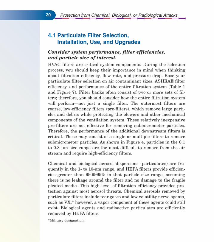
Consider system performance, filter efficiencies,and particle size of interest.HVAC filters are critical system components. During the selectionprocess, you should keep their importance in mind when thinkingabout filtration efficiency, flow rate, and pressure drop. Base yourparticulate filter selection on air contaminant sizes, ASHRAE filterefficiency, and performance of the entire filtration system (Table 1and Figure 7). Filter banks often consist of two or more sets of fil-ters; therefore, you should consider how the entire filtration systemwill perform—not just a single filter. The outermost filters arecoarse, low-efficiency filters (pre-filters), which remove large parti-cles and debris while protecting the blowers and other mechanicalcomponents of the ventilation system. These relatively inexpensivepre-filters are not effective for removing submicrometer particles.Therefore, the performance of the additional downstream filters iscritical. These may consist of a single or multiple filters to removesubmicrometer particles. As shown in Figure 4, particles in the 0.1to 0.3 µm size range are the most difficult to remove from the airstream and require high-efficiency filters.
Chemical and biological aerosol dispersions (particulates) are fre-quently in the 1- to 10-µm range, and HEPA filters provide efficien-cies greater than 99.9999% in that particle size range, assumingthere is no leakage around the filter and no damage to the fragilepleated media. This high level of filtration efficiency provides pro-tection against most aerosol threats. Chemical aerosols removed byparticulate filters include tear gases and low volatility nerve agents,such as VX;* however, a vapor component of these agents could stillexist. Biological agents and radioactive particulates are efficientlyremoved by HEPA filters.
*Military designation.

Filtration and Air-Cleaning Systems
Figure 7. Comparison of collection efficiency and particle size fordifferent filters [Ensor et al. 1991].
21

Protection from Chemical, Biological, or Radiological Attacks
Understand performance differences between filter types.When selecting particulate air filters, you must choose betweenmechanical or electrostatic filters. Keep in mind the already men-tioned differences between the two main filter classifications, suchas collection mechanism and pressure drop differences. Liquidaerosols are known to cause great reductions in the collection effi-ciencies of many electrostatic filters, and some studies have shownthat ambient aerosols may also degrade performance. The degrada-tion is partially related to the stability of the electrostatic charge.Pressure drop in an electrostatic filter (having less packing density)generally increases at a much slower rate than that of a similar effi-ciency mechanical filter. Pressure drop is frequently used inmechanical filters to determine filter change out, but is an unreli-able indicator for change-out of electrostatic filters. Other measures,such as collection efficiency or time of use, are more suited for deter-mining electrostatic filter change-out schedules.
Electrostatic filters may be an acceptable choice for some buildingprotection applications, but you should recognize that there are lim-itations and compromises associated with these filters. The filterefficiency rating given by the manufacturer is likely to be substan-tially higher than what the filter will actually achieve when used.Require your filter supplier to state the type of media used in the fil-ters of interest and provide data showing how these filters performover time. This will help you to determine whether these lower costfilters will meet your building’s air filtration needs.
Consider total life-cycle costs.• Filter cost, always a consideration, is directly related to
efficiency, duration of effectiveness, and collection mechanism.Mechanical filters (pleated glass fiber) are quite likely to be moreexpensive than electrostatic (polymeric media) filters, but bothmay have the same initial fractional collection efficiency.However, over time the two types of filters will performdifferently.
22

Filtration and Air-Cleaning Systems 23
• Total life-cycle cost (i.e., energy costs, maintenance, disposal,replacement, etc.) is another consideration, which includes morethan just the initial purchase price. You will minimize total costby selecting the optimum change-out schedule, based on filter lifeand power requirements (Figure 8). Multiple filters can extendthe life of the more expensive, high-efficiency filters. For example,one or more low-efficiency, disposable pre-filters, installedupstream of a HEPA filter, can extend the HEPA filter life by atleast 25%. If the disposable filter is followed by a 90% extendedsurface filter, the life of the HEPA filter can be extended by almost900% [ACGIH 2001]. However, you should not assume that thebest way to proceed is to use a pre-filter. First, you should weighthe cost of pre-filter replacement and pressure drop against theextended life of the primary filter. You may find that for the sameoverall efficiency, it is more cost-effective to avoid pre-filters and,instead, to change the primary filters more frequently. Make thisdecision by weighing the operating cost analysis against the cap-ture efficiencies provided by different systems.
Consider all of the elements affected by filter upgrades.Upgrading your filtration system may require significant changes inthe mechanical components of your HVAC system, depending uponthe component capacities. You should consider both the directand indirect impact of upgrading your filtration system. With lower-efficiency filters, the final (loaded or dirty) pressure drop is often inthe range of 125 to 250 Pascals (Pa) (0.5 to 1.0 in. water gauge).Higher quality filters may have an initial pressure drop higher than125 Pa (0.5 in. water gauge) and a final pressure drop of as high as325 Pa (1.5 in. water gauge). You should consider the capacity of yourexisting HVAC system. Many systems (e.g., light-commercial, roof-top package units) do not have the fan capacity to handle the higherpressure drop associated with higher-efficiency filters. If the pressuredrop of the filters installed in the system is too high, the HVAC sys-tem may be unable to deliver the designed volume of air to the occu-pied spaces. Higher capacity fans may be needed to overcome

Protection from Chemical, Biological, or Radiological Attacks24
Figure 8. Relationship among total cost, filter life, andpower requirements.* By selecting the appro-priate change out schedule based upon theoptimum final pressure drop, the total costcan be minimized.
the increased resistance, caused by higher-efficiency filters.Installation of such fans may not be feasible for many HVAC sys-tems because of insufficient physical space or other limitations. Insuch cases, extended surface filters (i.e., pleated, mini-pleat, orV-bank) or electrostatic filter media, which provide higher efficiencyand lower pressure drop, may be an alternative.
*This figure is adapted from NAFA [2001a].

Filtration and Air-Cleaning Systems 25
To be most effective, your filters should be used at their rated pres-sure drop and face velocity. Filter face velocity refers to the airstream velocity entering the filter. The rated pressure drop for eachfilter is given for a specific face velocity (typically 1.3 to 2.5 m/s or250 to 500 fpm), and the pressure drop increases with airflow veloc-ity. If you upgrade to higher-efficiency filters, the size and shape ofyour filter rack may need to be changed, in part, to assure appropri-ate face velocities. High-efficiency filters may experience a signifi-cant drop in collection efficiency if they are operated at too high of aface velocity (Figure 9).
Conduct periodic quantitative performance evaluations.You should use a quantitative evaluation to determine the total sys-tem efficiency. You should perform the evaluation for various parti-cle sizes and at the appropriate system flow rate. You can use yourevaluation of the results to implement further modifications (e.g.,improved filter seals, etc.). Information on quantitative evaluationsof HVAC systems and filter performance can be found in theASHRAE HVAC Systems and Equipment Handbook [ASHRAE2000] and the NAFA Guide to Air Filtration [NAFA 2001a].
Building owners and managers who cannot feasibly upgrade totraditional high-efficiency mechanical filters may considerextended surface or electrostatic filter systems as an attractivelow-cost alternative. Energy costs are minimized by the rela-tively low-pressure drop across these filters, and costly HVACupgrades (modifications that may be required for higher-effi-ciency mechanical filters) are frequently avoided. Used properly,both types of filters can provide increased protection to a build-ing and its occupants. However, you should closely monitor fil-tration efficiency of electrostatic filters that may substantiallydegrade with time.

Protection from Chemical, Biological, or Radiological Attacks26
Figure 9. Effect of face velocity on the collection efficiencyand the most penetrating particle size (MPPS).
4.2 Sorbent Selection, Installation, and UseChoosing the appropriate sorbent or sorbents for an airborne con-taminant is a complex decision, and you, in consultation with a qual-ified professional, should consider many factors. Before proceeding,seriously consider the issues associated with the installation of sor-bent filters for the removal of gaseous contaminants from your build-ing’s air, as this is a less common practice than the installation ofparticulate filtration. Sorbent filters should be located downstreamof the particulate filters. This arrangement will allow the sorbent tocollect vapors, generated from liquid aerosols that collect on the par-ticulate filter, and reduce the amount of particulate reaching the
Filtration and Air-Cleaning Systems 27
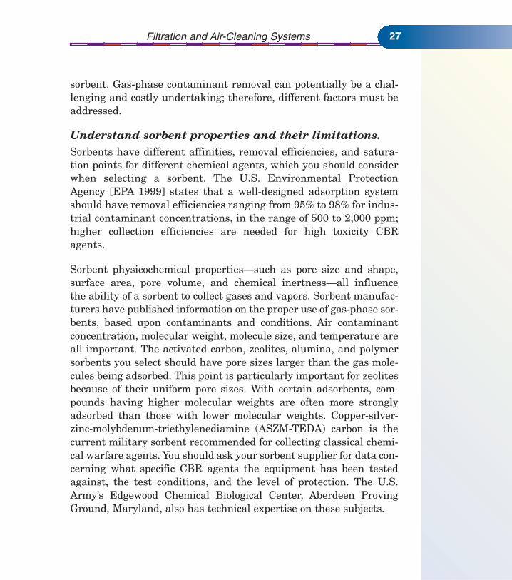
sorbent. Gas-phase contaminant removal can potentially be a chal-lenging and costly undertaking; therefore, different factors must beaddressed.
Understand sorbent properties and their limitations.Sorbents have different affinities, removal efficiencies, and satura-tion points for different chemical agents, which you should considerwhen selecting a sorbent. The U.S. Environmental ProtectionAgency [EPA 1999] states that a well-designed adsorption systemshould have removal efficiencies ranging from 95% to 98% for indus-trial contaminant concentrations, in the range of 500 to 2,000 ppm;higher collection efficiencies are needed for high toxicity CBRagents.
Sorbent physicochemical properties—such as pore size and shape,surface area, pore volume, and chemical inertness—all influencethe ability of a sorbent to collect gases and vapors. Sorbent manufac-turers have published information on the proper use of gas-phase sor-bents, based upon contaminants and conditions. Air contaminantconcentration, molecular weight, molecule size, and temperature areall important. The activated carbon, zeolites, alumina, and polymersorbents you select should have pore sizes larger than the gas mole-cules being adsorbed. This point is particularly important for zeolitesbecause of their uniform pore sizes. With certain adsorbents, com-pounds having higher molecular weights are often more stronglyadsorbed than those with lower molecular weights. Copper-silver-zinc-molybdenum-triethylenediamine (ASZM-TEDA) carbon is thecurrent military sorbent recommended for collecting classical chemi-cal warfare agents. You should ask your sorbent supplier for data con-cerning what specific CBR agents the equipment has been testedagainst, the test conditions, and the level of protection. The U.S.Army’s Edgewood Chemical Biological Center, Aberdeen ProvingGround, Maryland, also has technical expertise on these subjects.

Protection from Chemical, Biological, or Radiological Attacks28
Understand performance parametersand prevent breakthrough.Sorbents are rated in terms of adsorption capacity (i.e., the amountof the chemical that can be captured) for many chemicals. This capac-ity rises as concentration increases and temperature decreases. Therate of adsorption (i.e., the efficiency) falls as the amount of contam-inant captured grows. Information about adsorption capacity—avail-able from manufacturers—will allow you to predict the service life ofa sorbent bed. Sorbent beds are sized on the basis of challenge agentand concentration, air velocity and temperature, and the maximumallowable downstream concentration.
Gases are removed in the sorbent bed’s mass transfer zone. As thesorbent bed removes gases and vapors, the leading edge of this zoneis saturated with the contaminant, while the trailing edge is clean,as dictated by the adsorption capacity, bed depth, exposure history,and filtration dynamics. Significant quantities of an air contaminantmay pass through the sorbent bed if breakthrough occurs. However,you can avoid breakthrough by selecting the appropriate quantity ofsorbent and performing regular maintenance.
A phenomenon known as channeling may occur in sorbent beds andshould be avoided. Channeling occurs when a greater flow of airpasses through the portions of the bed that have lower resistance. Itis caused by non-uniform packing, irregular particle sizes andshapes, wall effects, and gas pockets. If channeling occurs within asorbent bed, it can adversely affect system performance.
Establish effective maintenance schedulesbased on predicted service life.When determining sorbent bed maintenance schedules and costs,you should consider service life of the sorbent. All sorbents have

Filtration and Air-Cleaning Systems 29
limited adsorption capacities and require scheduled maintenance.The effective residual capacity of an activated carbon sorbent bed isnot easily determined while in use, and saturated sorbents can re-emit collected contaminants. Sorbent life depends upon bed volumeor mass and its geometric shape, which influences airflow throughthe sorbent bed. Chemical agent concentrations and other gases(including humidity) affect the bed capacity. Because of differencesin affinities, it is possible that one chemical may displace anotherchemical, which can be re-adsorbed downstream or forced out of thebed. Most sorbents come in pellet form, which makes it possible tomix them. Mixed- and/or layered-sorbent beds permit effectiveremoval of a broader range of contaminants than possible with a sin-gle sorbent. Many sorbents can be regenerated, but it is importantto follow the manufacturer’s guidance closely to ensure that youreplace or regenerate sorbents in a safe and effective manner.
Don’t reuse chemically active sorbents. Some chemically active sorbents are impregnated with strong oxi-dizers, such as potassium permanganate. The adsorbent part of thebed captures the target gas and gives the oxidizer time to react anddestroy other agents. You should not reuse chemically active sor-bents because the oxidizer is consumed over time. If the adsorbentbed is exposed to very high concentrations of vapors, exothermicadsorption could lead to a large temperature rise and filter bed igni-tion. This risk can be exacerbated by the nature of impregnationmaterials. It is well known that lead and other metals can signifi-cantly lower the spontaneous ignition temperature of a carbon filterbed. The risk of sorbent bed fires is generally low and can be furtherminimized by ensuring that air-cleaning systems are located awayfrom heat sources and that automatic shut-off and warning capabil-ities are included in the system.

Protection from Chemical, Biological, or Radiological Attacks30
4.3 A Word about Filter or SorbentBypass and Air Infiltration
Ideally, all airflow should pass through the installed filters of theHVAC system. However, filter bypass, a common problem, occurswhen air flows around a filter or through some other unintendedpath. Preventing filter bypass becomes more important as filter col-lection efficiency and pressure drop increase. Airflow around the fil-ters result from various imperfections, e.g., poorly sealed filters,which permit particles to bypass the filters, rather than passingdirectly into the filter media. Filters can be held in place with aclamping mechanism, but this method may not provide an airtightseal. The best high-efficiency filtration systems have gaskets andclamps that provide an airtight seal. Any deteriorating or distortedgaskets should be replaced and checked for leaks. You can visuallyinspect filters for major leakage around the edges by placing a lightsource behind the filter; however, the best method of checking forleaks involves a particle counter or aerosol photometer. Finally, nofaults or other imperfections should exist within the filter media,and you should evaluate performance using a quantitative test, asdescribed in the literature [NAFA 2001a; ASHRAE 2000].
Another issue to consider is infiltration of outdoor air into the build-ing. Air infiltration may occur through openings in the buildingenvelope—such as doors, windows, ventilation openings, and cracks.Typical office buildings are quite porous and may have leakage ratesranging from 0.03 to 0.6 m3/min per m2 of floor space (0.1 to 2cfm/ft2), at pressures of 50 Pa [U.S. Army Corps of Engineers 2001].To achieve the most effective filtration and air cleaning systemagainst external CBR threats, you must minimize outdoor air leak-age into your building. Dramatically reducing leakage can beimpractical for many older buildings, which may have large leakageareas, operable windows, and decentralized HVAC systems. In theseinstances, other protective measures, such as those outlined in the

Filtration and Air-Cleaning Systems 31
NIOSH Guidance for Protecting Building Environments fromAirborne Chemical, Biological, or Radiological Attacks, should beconsidered.
Initially, you must decide which portions of your building to includein the protective envelope. Areas requiring high air exchange, suchas some mechanical rooms, may be excluded. To maximize buildingprotection, reduce the infiltration of unfiltered outdoor air byincreasing the air tightness of the building envelope (eliminatingcracks and pores) and introducing enough filtered air to place thebuilding under positive pressure with respect to the outdoors. It ismuch easier and more cost efficient to maintain positive pressure ina building if the envelope is tight, so use these measures in combi-nation. The U.S. Army Corps of Engineers recommends that forexternal terrorist threats, buildings should be designed to providepositive pressure at wind speeds up to 12 km/hr (7 mph). Designingfor higher wind speeds will give even greater building protection[U.S. Army 1999].
In buildings that have a leaky envelope, maintaining positive indoorpressure may be difficult to impossible. Interior/exterior differentialair pressures are in constant flux due to wind speed and direction,barometric pressure, indoor/outdoor temperature differences (stackeffect), and building operations, such as elevator movement or HVACsystem operation. HVAC system operating mode is also important inmaintaining positive indoor pressure. For example, many HVAC sys-tems use an energy savings mode on the weekends and at night toreduce outside air supply and, hence, lower building pressurization.In cold climates, you should ensure that an adequate and properlypositioned vapor barrier exists before you pressurize your building tominimize condensation, which may in turn, cause mold and otherproblems. All of these factors (leaky envelope, negative indoor airpressure, energy savings mode) influence building air infiltration andmust be considered when you tighten your building. You can use

Protection from Chemical, Biological, or Radiological Attacks32
building pressurization or tracer gas testing to evaluate the air tight-ness of your building envelope. Information on evaluating buildingenvelope tightness, air infiltration, and water vapor management isdescribed in the ASHRAE Fundamentals Handbook [2001].
4.4 Recommendations RegardingOperations and Maintenance
Filter performance depends on proper selection, installation, opera-tion, testing, and maintenance. The scheduled maintenance pro-gram should include procedures for installation, removal, and dis-posal of filter media and sorbents. Only adequately trained person-nel should perform filter maintenance and only while the HVAC sys-tem is not operating (locked out/tagged out) to prevent contaminantsfrom being entrained into the moving air stream.
Do not attempt HVAC system maintenancefollowing a CBR release without first consultingappropriate emergency response and/or health andsafety professionals. If a CBR release occurs in or near your building, significant hazardsmay be present, particularly within the building’s HVAC system. Ifthe HVAC and filtration systems have protected the building fromthe CBR release, contaminants will have collected on HVAC systemcomponents, on the particulate filters, or within the sorbent bed.These accumulated materials present a hazard to personnel servic-ing the various systems. Therefore, before servicing these systemsfollowing a release, consult with the appropriate emergencyresponse and/or health and safety professionals to develop a plan forreturning the HVAC systems and your building to service. Becauseof the wide variety of buildings, contaminants, and scenarios, it isnot possible to provide a generic plan here. However, such a planshould include requirements for personnel training and appropriatepersonal protective equipment.
Filtration and Air-Cleaning Systems 33
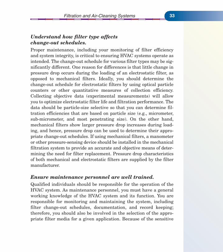
Understand how filter type affectschange-out schedules.Proper maintenance, including your monitoring of filter efficiencyand system integrity, is critical to ensuring HVAC systems operate asintended. The change-out schedule for various filter types may be sig-nificantly different. One reason for differences is that little change inpressure drop occurs during the loading of an electrostatic filter, asopposed to mechanical filters. Ideally, you should determine thechange-out schedule for electrostatic filters by using optical particlecounters or other quantitative measures of collection efficiency.Collecting objective data (experimental measurements) will allowyou to optimize electrostatic filter life and filtration performance. Thedata should be particle-size selective so that you can determine fil-tration efficiencies that are based on particle size (e.g., micrometer,sub-micrometer, and most penetrating size). On the other hand,mechanical filters show larger pressure drop increases during load-ing, and hence, pressure drop can be used to determine their appro-priate change-out schedules. If using mechanical filters, a manometeror other pressure-sensing device should be installed in the mechanicalfiltration system to provide an accurate and objective means of deter-mining the need for filter replacement. Pressure drop characteristicsof both mechanical and electrostatic filters are supplied by the filtermanufacturer.
Ensure maintenance personnel are well trained. Qualified individuals should be responsible for the operation of theHVAC system. As maintenance personnel, you must have a generalworking knowledge of the HVAC system and its function. You areresponsible for monitoring and maintaining the system, includingfilter change-out schedules, documentation, and record keeping;therefore, you should also be involved in the selection of the appro-priate filter media for a given application. Because of the sensitive

Protection from Chemical, Biological, or Radiological Attacks34
nature of these systems, appropriate background checks should becompleted and assessed for any personnel who have access to theHVAC equipment.
Handle filters with care and inspect for damage.Mechanical filters, often made of glass fibers, are relatively delicateand should be handled carefully to avoid damage. Filters enclosed inmetal frames are heavy and may cause problems because of theadditional weight they place on the filter racks. The increasedweight may require a new filter support system that has verticalstiffeners and better sealing properties to ensure total systemintegrity. Polymeric electrostatic filters are more durable and lessprone to damage than mechanical filters.
To prevent installation of a filter that has been damaged in storageor one that has a manufacturing defect, you should check all filtersbefore installing them and visually inspect the seams for totalintegrity. You should hold the filters in front of a light source andlook for voids, tears, or gaps in the filter media and filter frames.Take special care to avoid jarring or dropping the filter element dur-ing inspection, installation, or removal.
Wear appropriate personal protectiveequipment when performing change-out.Recent laboratory studies have indicated that re-aerosolization ofbioaerosols from HEPA and N95 respirator filter material is unlikelyunder normal conditions [Reponen et al. 1999; Gwangpyo et al. 1998].These studies concluded that biological aerosols are not likely tobecome an airborne infectious problem once removed by a HEPAfilter (or other high-efficiency filter material); however, the risksassociated with handling loaded filters in ventilation systems, under

Filtration and Air-Cleaning Systems 35
field-use conditions, need further study. Persons performing mainte-nance and filter replacement on any ventilation system that is likelyto be contaminated with hazardous CBR agents should wear appro-priate personal protective equipment (respirators, gloves, etc.) inaccordance with Occupational Safety and Health Administration(OSHA) standards 29 Code of Federal Regulations (CFR) 1910.132and 1910.134. For example, the Centers for Disease Control andPrevention (CDC) recommends NIOSH-approved 95% efficientnon-oil mist environment (N95) respirators and gloves for a workerperforming filter maintenance in a health care setting where thespread of tuberculosis is a concern.
Maintenance and filter change-out should be performed only when asystem is shut down to avoid re-entrainment and system exposure.You should place old filters in sealed plastic bags upon removal.Where feasible, particulate filters may be disinfected in a 10%bleach solution or other appropriate biocide before removal. Not onlyshould you shut down the HVAC system when you use disinfectingcompounds but also you should ensure that the compounds are com-patible with the HVAC system components they may contact.Decontaminating filters exposed to CBR agents requires knowledgeof the type of agent, safety-related information concerning thedecontaminating compounds, and proper hazardous waste disposalprocedures. Your local hazardous materials (HAZMAT) teams andcontractors should have expertise in these areas.
4.5 Note on Emerging TechnologiesRecently, a number of new technologies have been developed toenhance or augment HVAC filtration systems. Many of these tech-nologies have taken novel approaches to removing contaminantsfrom the building air stream. While some of these new systems maybe highly effective, many are unproven. Before you commit to one of

Protection from Chemical, Biological, or Radiological Attacks36
these new technologies for the protection of your building and itsoccupants, require the vendor to provide evidence that demonstratesthe effectiveness for your application. Some of the things you shoulddo include:
• Identify data showing the effectiveness and efficiency of the sys-tem. This data should be relevant to the application proposed foryour building (flow rate, contaminant concentration, etc.).
• Know the source of the data. Did independent researchers collectthe data, or was the research done by a vendor? While vendor-col-lected data can be useful, data collected by an independent organ-ization can reduce or eliminate biases. Where applicable, ask fordata collected using consensus protocols (i.e., ASHRAE, Instituteof Environmental Sciences and Technology [IEST], AmericanSociety for Testing and Materials [ASTM], Air-Conditioning andRefrigeration Institute [ARI]).
• Be concerned about long-term maintenance, possible hazards, orgenerated pollutants resulting from an experimental system.
• Be wary of anecdotal data or testimonials, particularly thoseexalting the new technology. While this information can be inter-esting and thought provoking, it may not be relevant to how wellthe system will work in your building.
• Talk with the vendor’s customers who have implemented the sys-tems of interest. Are they satisfied with the system, equipment,installation, and vendor? What problems did they encounter andhow were these resolved? If they had it to do over, what wouldthey do differently?
New technologies can and will have a place in protecting a building’sairborne environment. However, you should ensure that resourcesare spent on proven systems and technologies that will continue tobe effective when needed.

Filtration and Air-Cleaning Systems 37
5. ECONOMIC CONSIDERATIONSCosts associated with air filtration and air-cleaning systems can bedivided into three general categories: initial costs, operating costs,and replacement costs. Although some users might consider only theinitial costs when selecting an appropriate filtration system, it isimportant to weigh carefully all of the life-cycle costs. The HVACdesign engineer should assist you in understanding the costs andbenefits of various air-filtration options.
5.1 Initial CostsInitial costs include those for original equipment—the filter racksystem, individual filters, and auxiliary equipment—and the usualdirect and indirect costs associated with installing a new systemrelated to the electrical, ducting, and plumbing work. The total pur-chase cost of the filtration system is the sum of the costs for the fil-ter rack system, filters, and auxiliary equipment; instruments andcontrols; taxes; and freight. For particulate filters, expenses gener-ally increase as filter efficiency and quality increase. For some appli-cations, a lower-efficiency filter (e.g., MERV 12) may be adequateand can be used instead of a HEPA filter (MERV 17) to control costswhile achieving adequate performance. For gas-phase filters, thecost differences among sorbents can be dramatic. For example, nat-ural zeolite, alumina, and activated carbon are generally the leastexpensive sorbents. Specialty carbon (such as ASZM-TEDA), syn-thetic zeolite, and polymers are typically much more expensive (asmuch as 20 times more expensive). A trade-off to consider is that car-bon needs to be replaced frequently (every 6 months to 5 years),while zeolite and polymer replacement can occur less frequently.
Other factors that influence the initial costs of a system include thevolumetric flow rate, contaminant concentrations, and in the case ofadsorption systems—bed size, sorbent capacity, and humidity.
Protection from Chemical, Biological, or Radiological Attacks38
Volumetric flow and pressure drop may be the most important factorsbecause they determine the size of the ductwork and filter rack, aswell as the blower and motor. Effective sorbent filters typically havea resistance of at least 125 Pa (0.5 in. water gauge) for thin beds and500 Pa (2.0 in. water gauge) or more for deep beds.
5.2 Operating CostsAnnual operating costs include operating labor and materials,replacement filters, maintenance (labor and materials), utilities,waste disposal, and equipment depreciation. These costs vary, basedupon the specific filtration system. Many of these costs should beconsidered in terms of the present value of money. Operating andmaintenance labor costs depend on the filter type, size, and operat-ing difficulty of a particular unit. Electrical costs to operate theblowers are directly related to airflow through and pressure dropacross the filters.
5.3 Replacement CostsAn important part of replacement costs relates to the estimated lifeof the filtration system. As filter life increases, the cost per operat-ing hour falls. However, when mechanical filters are exposed to con-taminated air, the pressure drop across them increases, and thiscan increase electrical costs. Costs can be minimized by your evalu-ation of the system and selection of the best final pressure drop toreplace filters, based upon extended filter life and minimized powerrequirements.
Factors affecting particulate filter life include contaminant concen-tration, particle size distributions, airflow rates, and filter efficiencyand quality. Particulate filters are frequently used in multiple stagesto extend the life of more expensive final stage filters. Factors affect-ing gas-phase filter life include removal capacity and sorbentweight, sorbent collection efficiency, airflow rates, and molecular

Filtration and Air-Cleaning Systems 39
weight and concentration of the contaminant. Filter replacementlabor costs depend on the number, size, and type of filters, theiraccessibility, how they are held in the filter rack, and other factorsaffecting labor.
5.4 Cost DataThe cost of air-filtration and pressurization systems in new con-struction is about $6/ft2 of floor area for basic, continuous HEPA andgas-phase V-bed filtration, using activated carbon. Operating costsare on the order of $5.40/m2/yr ($0.50/ft2/yr). Adding sensors andon-demand military style radial HEPA or carbon filters can cost upto $430/m2 ($40/ft2), and operating costs can increase to over$16/m2/yr ($1.50/ft2/yr). The cost of renovating an existing systemmay be up to three times more than the cost of new construction,depending on the amount of demolition, new ductwork, and enlarge-ment of mechanical spaces required.
In most filter applications, the size of the filter bank is determinedby the size of the heat transfer coils. The filter is placed upstream ofthe coils to reduce soiling. The filter bank is sized to the coil becausethe coil area is the point in the ducted portion of the air distributionsystem having the lowest velocity. The lower velocity of air throughan air filter will result in a lower pressure drop across the filter. Alower pressure drop across the filter leads to a lower system pres-sure drop, resulting in lower fan horsepower and operating energy.In most cases, sizing a moderately efficient air-filtration system tobe larger than the coil area will result in high filter rack costs, whichare not offset by a significantly reduced filter pressure drop.However, as the cost of energy increases, the benefit of lower pres-sure drop filters and larger filter racks becomes apparent.
Required fan horsepower is related to the total system pressuredrop. For example, improving filtration to increase the filter pres-sure drop from 250 to 500 Pa (1.0 to 2.0 in. water gauge) will boost

Protection from Chemical, Biological, or Radiological Attacks40
the total system pressure drop from 1000 to 1250 Pa (4.0 to 5.0 in.water gauge). However, in this example, the higher pressure dropwill increase the required fan horsepower by roughly 40%.
The costs and benefits of the filters should be considered. A 25%ASHRAE filter (0.61 by 0.61 m [2 by 2 ft]) will cost approximately$10 to $20, while an 80% or 90% ASHRAE filter will cost in therange of $40 to $75, respectively. For example, if a system uses60 filters at a cost of $70 each and they are replaced annually, thepresent value of the enhanced filters over 25 years will cost approx-imately $14,000. The benefits of higher-efficiency filters may includeless need for coil cleaning and a reduced pressure drop due to clean-er coils. If these two factors save $1,000 annually, the present valueof the savings is $17,500, which compensates for the increasedfilter cost.
A standard HEPA filter (0.61 by 0.61 m [2 by 2 ft]) costs approxi-mately $100 to $250. Initial HEPA filter pressure drops are around250 to 325 Pa (1.0–1.5 in. water gauge), depending on the designflow rate, fan performance curve, and related issues. Peak pressuredrops can be as high as 750 Pa (3.0 in. water gauge). Analysis hascompared the cost efficiency (particle removal rate divided by lifecycle costs) of HEPA filters to ASHRAE 25%, 80%, and 90% filters[Kowalski et al. 2002]. This analysis showed that ASHRAE 80% and90% filters are substantially more cost efficient than HEPA filters.
Filter replacement time must be a trade-off with the energy cost,which is associated with driving the air through the high-pressuredrop filter. The higher the cost of energy, the more frequently thebuilding operator should change out the higher-pressure drop filters.The number of filters that should be used in the design is limited bythe available space and energy savings from reducing the systempressure drop. If energy is inexpensive, then fewer filters may beused. However, this does not take into account the environmental

Filtration and Air-Cleaning Systems 41
impact of wasted energy. If energy costs are high or are expected toincrease over the life of the system, then selecting the maximumnumber of filters for the available space should be considered, alongwith filter rack costs.
The cost of a standard size (0.61 by 0.61 m [2 by 2 ft]), individual,high-efficiency gas-phase filter is about $2,000 to $4,000. Thesehigh filter costs drive the design to use as few filters as possible.High energy costs (>$0.40 per kilowatt hour [kW˙h]) are requiredbefore it is cost effective to increase the number of filters, thus,reducing the system pressure drop (energy) costs. Lower-efficiencyand lower-cost gas-phase filters are available for indoor air qualityapplications. Less expensive gas-phase filters should be designedusing the cost trade-off techniques described for particulate filters.However, you should recognize that these lower-cost options may nothave the adequate adsorption capacity needed to provide protectionduring a CBR event.
6. CONCLUSIONSFiltration and air-cleaning systems may protect a building and itsoccupants from the effects of a CBR attack. Although it is impossibleto completely eliminate the risk from an attack, filtration and air-cleaning systems are important components of a comprehensiveplan to reduce the consequences. CBR agents can effectively beremoved by properly designed, installed, and well-maintained filtra-tion and air-cleaning systems. These systems have other benefitsbesides reducing clean-up costs and delays, should a CBR eventoccur. These benefits include improving building cleanliness,improving HVAC system efficiency, potentially preventing cases ofrespiratory infection, reducing exacerbations of asthma and aller-gies, and generally improving building indoor air quality. Poorindoor air quality has also been associated with eye, nose, and throatirritation, headaches, dizziness, difficulty concentrating, and fatigue[Spengler et al. 2000].

Protection from Chemical, Biological, or Radiological Attacks42
Initially, you must fully understand the design and operation of yourexisting building and HVAC system. Backed with that knowledge,along with an assessment of the current threat and the level of pro-tection you want from your system, you can make an informed deci-sion regarding your building’s filtration and air-cleaning needs. Insome situations, the existing system may be adequate, while in oth-ers major changes or improvements may be merited.
In most buildings, mechanical filtration systems for aerosol removalare more common than sorbents for gas and vapor removal.Decisions regarding collection efficiency levels of particulate filtersshould be made with respect to ASHRAE Standards 52.1 and 52.2.Selection of the best sorbent or sorbents for gaseous contaminants ismore complex. ASZM-TEDA carbon is recommended for classicalchemical warfare agents. Other sorbents have been developed to col-lect specific TICs. To optimize effectiveness, you should minimize airinfiltration and eliminate filter bypass. Maintenance plans andoperations should ensure that the system works as intended for longperiods. Life-cycle analysis will ensure that filtration and air-clean-ing options satisfy your building’s needs while providing protectionto the building occupants.

Filtration and Air-Cleaning Systems 43
7. KEY REFERENCES AND BIBLIOGRAPHY
7.1 Key ReferencesACGIH [2001]. Industrial ventilation: a manual of recommendedpractice. Cincinnati, OH: American Conference of GovernmentalIndustrial Hygienists, Inc.
ANSI/ASHRAE [1992]. ASHRAE Standard 52.1: gravimetric anddust-spot procedures for testing air-cleaning devices used in generalventilation for removing particulate matter. Atlanta, GA: AmericanSociety of Heating, Refrigerating, and Air-Conditioning Engineers,Inc., p. 32.
ANSI/ASHRAE [2001]. ASHRAE Standard 52.2: method of testinggeneral ventilation air-cleaning devices for removal efficiency by par-ticle size. Atlanta, GA: American Society of Heating, Refrigerating,and Air-Conditioning Engineers, Inc., p. 41.
ASHRAE [2000]. ASHRAE handbook: HVAC systems and equip-ment. Atlanta, GA: American Society of Heating, Refrigerating, andAir-Conditioning Engineers, Inc.
ASHRAE [2001]. ASHRAE handbook: fundamentals. Atlanta, GA:American Society of Heating, Refrigerating, and Air-ConditioningEngineers, Inc.
ASHRAE [2002]. Risk management guidance for health and safetyunder extraordinary incidents. Atlanta, GA: American Society ofHeating, Refrigerating, and Air-Conditioning Engineers, Inc., pp. 1–8.
Blewett WK [2002]. Fail-safe application and design of air condi-tioners for NBC collective protection systems. Aberdeen ProvingGround, MD: Edgewood Chemical Biological Center.
Brown RC [1993]. Air filtration: an integrated approach to the theoryand application of fibrous filters. Oxford, England: Pergamon Press.

Protection from Chemical, Biological, or Radiological Attacks44
CBIAC [1999]. Determination of optimum sorbent material forcollection and air desorption of chemical warfare agents. Ft. Belvoir,VA: Chemical Warfare/Chemical and Biological Defense InformationAnalysis Center, Department of Defense, p. 20.
CBIAC [2001]. Air purification technologies. Ft. Belvoir, VA:Chemical Warfare/Chemical and Biological Defense InformationAnalysis Center, Department of Defense, p. 21.
Cooper CD, Alley FC [1994]. Air pollution control—a designapproach. Prospect Heights, IL: Waveland Press, Inc.
Davies CN [1973]. Air Filtration. New York, NY: Academic Press.
Ensor DS, Hanley JT, Sparks LE [1991]. Particle-size-dependentefficiency of air cleaners. Washington D.C.: IAQ 1991, HealthyBuildings/IAQ, pp. 334–336.
EPA [1998]. Zeolite—a versatile air pollutant adsorber. ResearchTriangle Park, NC: U.S. Environmental Protection Agency, p. 10.
EPA [1999]. Choosing an adsorption system for VOC: carbon, zeolite,or polymers? Research Triangle Park, NC: U.S. EnvironmentalProtection Agency, p. 24.
Gwangpyo K, Burge HA, Muilenberg M, Rudnick S, First M [1998].Survival of Mycobacteria on HEPA filter material. J Amer BiolSafety Assoc 3(2):65–78.
Hinds WC [1982]. Aerosol technology: properties, behavior, andmeasurement of airborne particles. New York, NY: Wiley.
Kowalski WJ, Bahnfleth WP [2002]. Airborne-microbe filtration inindoor environments. HPAC Engineering 74(1):57-69.
Kowalski WJ [2002]. Immune Building Systems Technology. NewYork, NY: McGraw-Hill.
Licht W [1988]. Air pollution control engineering. New York, NY:Marcel Dekker, Inc.

Filtration and Air-Cleaning Systems 45
Morrison RW [2001]. NBC filter performance. Aberdeen ProvingGround, MD: Edgewood Chemical Biological Center TechnicalReport.
NAFA [1997]. Installation, operation, and maintenance of air filtra-tion systems. Washington, DC: National Air Filtration Association.
NAFA [2001a]. Guide to air filtration. Washington, DC: National AirFiltration Association.
NIOSH [2002]. Guidance for protecting building environments fromairborne chemical, biological, or radiological attacks. Cincinnati,OH: U.S. Department of Health and Human Services, Centers forDisease Control and Prevention, National Institute for OccupationalSafety and Health, DHHS (NIOSH) Publication No. 2002–139, p. 28.
Reponen TA, Wang Z, Willeke K, Grinshspun SA [1999]. Survival ofMycobacteria on N95 personal respirators. Infect Control HospEpidemiol 20:237–41.
Spengler JD, Samet JM, McCarthy JF [2000]. Indoor air qualityhandbook. New York, NY: McGraw-Hill.
Suzuki M [1990]. Adsorption engineering. New York, NY: ElsevierScience Publishing Company.
U. S. Army [1990]. Potential military chemical/biological agents andcompounds. U.S. Army Field Manual 3–9. Washington, DC:Department of the Army, Headquarters.
U.S. Army Corps of Engineers [2001]. Draft report: protecting build-ings and their occupants from airborne hazards. Washington D.C.:U.S. Army Corps of Engineers, Engineering and ConstructionDivision, p. 22.
Yang RT [1987]. Gas separation by adsorption processes. Boston,MA: Butterworth Publishers.

Protection from Chemical, Biological, or Radiological Attacks46
7.2 BibliographyAIA [2001]. Building security through design. Washington, DC:
American Institute of Architects, p.4.
Alves BR, Clark AJ [1986]. An examination of the productsformed on reaction of hydrogen cyanide and cyanogen withcopper, chromium (6+) and copper-chromium (6+) impregnatedactivated carbons. Carbon 24: 287–294.
ANSI/ASHRAE [2001]. ASHRAE Standard 62: ventilation for accept-able indoor air quality. Atlanta, GA: American Society of Heating,Refrigerating, and Air-Conditioning Engineers Inc., p. 27.
Avery RH [1978]. Energy effective air filtration. Plant Engineering.
Barrett LW, Rousseau AD [1998]. Aerosol loading performance ofelectret filter media. Am Ind Hyg Assoc J 59:532–539.
BOMA [2002]. Emergency preparedness. Washington, DC: BuildingOwners and Managers Association International, p.170.
Brink JA, Burgrabe WF, Greenwell LE [1968]. Mist eliminators forsulfuric acid plants. Chem Eng Prog 64(11):82–86.
Brown PN [1989]. Effect of aging and moisture on the retention ofhydrogen cyanide by impregnated charcoals. Carbon 27:821–833.
Brown RC, Wake D, Gray R, Blackford DB, Bostock GJ [1988]. Effectof industrial aerosols on the performance of electrically chargedfilter material. Ann Occup Hyg 32(3):271–294.
Burroughs HE [2002]. Taking action against the new threat.Refrigeration Service Eng Soc J (RSES) 74(1):32–36.
CDC (Centers for Disease Control and Prevention) [2001]. Update:investigation of anthrax associated with intentional exposureand interim public health guidelines. MMWR 50(41):889–897.
Cooper DW [1980]. Mechanisms for electrostatic enhancement of fab-ric filter performance. Filtration and Separation 17(6):520–523.
Davies CN [1970]. The clogging of fibrous aerosol filters. Aerosol Sci1:35–39.

Filtration and Air-Cleaning Systems 47
Dennis WL [1973]. Effect of humidity on the efficiency of particulateair filters. Filtration and Separation 10(2):149–150.
Dixon TC, Meselson M, Guillemin, J, Hanna PC [1999]. Anthrax.N Engl J Med 341(11):815–826.
Doughty DT [1991]. Development of a chromium-free impregnatedcarbon for adsorption of toxic agents. Pittsburgh, PA: CalgonCarbon Corporation.
Fisher R, Hormats S [1954]. Charcoal. In: History of research anddevelopment of the chemical warfare service in World War II.Army Chemical Center 7.
Friedlander SK [1977]. Smoke, dust and haze fundamentals ofaerosol behavior. New York, NY: John Wiley and Sons.
GSA [2001]. Security in the workplace—informational material.U.S. General Services Administration.
Gupta A, Novick VJ, Biswas P, Monson PR [1993]. Effect of humidi-ty and particle hygroscopicity on the mass loading capacity ofhigh efficiency particulate air (HEPA) filters. Aerosol SciTechnol 19(1):94–107.
Henderson DA [1998]. Bioterrorism as a public health threat.Emerging Infectious Diseases 4(3):1–7.
Henderson DA [1999]. The looming threat of bioterrorism. Science283:1279–1282.
Inglesby TV, Henderson DA, Bartlett JG, Ascher MS [1999]. Anthraxas a biological weapon: medical and public health management.JAMA 281(18):1735–1745.
Karwacki CJ, Jones P [2000]. Technical report: toxic industrialchemicals: assessment of NBC filter performance. AberdeenProving Ground, MD: Edgewood Chemical Biological Center.
Karwacki CJ, Tevault DE, Mahle JJ, Buchanan JH, Buettner LC[1999]. Adsorption equilibria of isopropyl methylphosphonofluo-ridate (GB) on activated carbon at ultralow relative pressures.Langmuir 15.

Protection from Chemical, Biological, or Radiological Attacks48
Lee KW, Liu BYH [1980]. On the minimum efficiency and the mostpenetrating particle size for fibrous filters. J Air Pollut ControlAssoc 30:377–381.
Lee KW, Liu BYH [1981]. Experimental study of aerosol filtration byfibrous filters. Aerosol Sci Technol 1(1):35–46.
Lee KW, Liu BYH [1982]. Theoretical study of aerosol filtration byfibrous filters. Aerosol Sci Technol 1(2):147–162.
Liu BYH, Pui DYH, Rubow KL [1983]. Characteristics of air sam-pling filter media. In: Marple VA, Liu BYH, eds. Aerosols in themining and industrial work environments. Ann Arbor, MI: AnnArbor Science 3:989–1038.
Miller JD [2002]. Defensive filtration. ASHRAE Journal 44(12):18–23.
NAFA [2001b]. NAFA position statement on bio-terrorism.Washington D.C.: National Air Filtration Association.
NFPA [1991]. Fire protection handbook. Quincy, MA: National FireProtection Association.
Noyes WA [1946]. Military problems with aerosols and nonpersistentgases, summary technical report of division 10. Washington,D.C.: National Defense Research Committee.
NRC [1988]. Protection of Federal office buildings against terrorism.Washington, D.C.: Committee on the Protection of FederalFacilities Against Terrorism, Building Research Board,National Research Council: p. 60.
Vincent JH [1995]. Aerosol science for industrial hygienists. Oxford,U.K.: Pergamon.
Willeke K, Baron P, eds. [1993]. Aerosol measurement: principles,techniques, and applications. New York, NY: Van NostrandReinhold.

Filtration and Air-Cleaning Systems 49
Appendix A: OHS BUILDING AIRPROTECTION WORKGROUP MEMBERS
Kenneth Stroech, Chair White House Office of Homeland SecurityNancy H. Adams U.S. Environmental Protection AgencyAmy Alving Defense Advanced Research Projects AgencyMelvin Basye U.S. General Services AdministrationWade Belcher U.S. General Services AdministrationDavid F. Brown Argonne National LaboratoryWendy Davis-Hoover U.S. Environmental Protection AgencyG. Scott Earnest National Institute for Occupational Safety and HealthSteven Emmerich National Institute of Standards and TechnologyElissa Feldman U.S. Environmental Protection AgencyD. Shawn Fenn Federal Emergency Management AgencyScott Filer Argonne National LaboratoryJohn Girman U.S. Environmental Protection AgencyGeorge Glavis U.S. Department of StateMichael G. Gressel National Institute for Occupational Safety and HealthDavid Hansen U.S. Department of EnergyBrenda Harris Defense Threat Reduction AgencyJerome Hauer U.S. Department of Health and Human ServicesRichard Heiden U.S. ArmyRobert Kehlet Defense Threat Reduction AgencyRebecca Lankey White House Office of Science and Technology PolicyWilliam H. Lyerly U.S. Department of Health and Human ServicesKenneth R. Mead National Institute for Occupational Safety and HealthRudy Perkey U.S. NavyAndrew Persily National Institute of Standards and TechnologyWade A. Raines U.S. Postal ServiceLaurence D. Reed National Institute for Occupational Safety and HealthRich Sextro Lawrence Berkeley National LaboratoryMary Smith U.S. Environmental Protection AgencyPatrick F. Spahn U.S. Department of State

Protection from Chemical, Biological, or Radiological Attacks50
Nathan C. Tatum Agency for Toxic Substances and Disease RegistryJohn R. Thompson, Jr. Defense Advanced Research Projects AgencyRobert Thompson U.S. Environmental Protection AgencyJeanne Trelogan U.S. General Services AdministrationRobert C. Williams Agency for Toxic Substances and Disease RegistryDebra Yap U.S. General Services Administration

Filtration and Air-Cleaning Systems 51
Appendix B: CBR THREATS
The effects of the various CBR agents can vary widely. A brief descrip-tion of the effects of the different classes of agents is provided below.A more detailed discussion on the characteristics and effects of CBRagents can be found in some of the sources listed in the Reference sec-tion of this document.
Classical Chemical Warfare AgentsClassical chemical warfare agents include a wide variety of differentcompounds that can affect humans in various ways. Chemicalwarfare agents commonly exist as either a gas or liquid aerosol.Many of the blister and nerve agents, having low vapor pressures,are delivered as a liquid aerosol; while many other higher vaporpressure agents are gaseous. Blister agents, also known as vesi-cants, include sulfur and nitrogen mustards, as well as a variety ofarsenic-containing materials. Blister agents tend to have relativelylow volatility and modest acute toxicity, compared to other chemicalwarfare agents. Blood and choking agents are highly volatile inhala-tion hazards. Blood agents include hydrogen cyanide (AC), cyanogenchloride (CK), and arsine (SA). Choking agents include phosgene(CG), and diphosgene (DP). Nerve agents are derivatives oforganophosphate esters and are among the most toxic chemicalsknown. This class includes materials such as O-ethyl-S-(2-diiso-propyl aminoethyl) methyl phosphonothiolate (VX), ethylN,N-dimethyl phosphoroamido cyanidate (tabun), isopropyl methylphos-phonofluoridate (sarin), and pinacolyl methyl phosphonofluoridate(soman). Nerve agents have a wide range of volatilities and theirtoxicity is approximately 100 times higher than blood and chokingagents. Incapacitating agents are usually distinguished fromriot-control agents by their longer period of effectiveness, which maybe as long as days after exposure. Examples of incapacitating agents

Protection from Chemical, Biological, or Radiological Attacks52
include 3-quinuclidinyl benzilate (BZ); cannabinols; phenothiazines;fentanyls; and central nervous system stimulants, i.e., d-lysergicacid diethyl amide (LSD). Blister and nerve agents are stronglyadsorbed by activated carbon. Blood and choking agents are notstrongly retained by activated carbon, but additives such as metaloxides and other reactants found in the U.S. military carbonASZM-TEDA (see Table 2) may be used in the sorbent to degradethe hazard.
Toxic Industrial Chemicals and MaterialsToxic Industrial Chemicals (TICs) and Toxic Industrial Materials(TIMs) are commonly categorized by their hazardous properties,such as reactivity, stability, combustibility, corrosiveness, ability tooxidize other materials, and radioactivity [NFPA 1991]. For the pur-poses of collection on a sorbent, gaseous agents can be divided intothe following categories: organic vapors (i.e., cyclohexane), acidgases (i.e., hydrogen sulfide), base gases (i.e., ammonia), and spe-cialty chemicals (i.e., formaldehyde or phosgene). TICs that have acombination of high toxicity and ready availability are of principalconcern. Those having a volatility of less than 10 torr at room tem-perature are effectively removed by physical adsorption. However, anumber of high toxicity TICs, produced industrially on a large scale,have volatilities higher than 10 torr at 20˚C and are more difficult tocollect. Potential approaches in addressing performance shortfallsinclude (1) development of structured filter beds to deal with specif-ic chemicals and (2) impregnation treatments, developed to addressseveral high-priority TICs. Building owners and managers shouldtake into account the potential threat posed by large quantities ofTICs and TIMs that may be found in the vicinity of their building.

Filtration and Air-Cleaning Systems 53
Table 2. Mechanisms of agent vapor filtration by ASZM-TEDA carbon
Agent Filtration mechanism
Nerve Strong physical adsorption, generally followed by slow hydrolysis ofthe adsorbed agent.
Blister Strong physical adsorption, generally followed by slow hydrolysis ofthe adsorbed agent.
Phosgene Weak physical adsorption combined with agent decomposition, affected(choking agent) by the impregnates. Phosgene hydrolysis to form hydrogen chloride
and carbon dioxide. The hydrogen chloride reacts with the copper andzinc carbonate impregnates to form copper and zinc chlorides.
Cyanogen chloride Weak physical adsorption combined with agent decomposition, affected(blood agent) by the impregnates. Cyanogen chloride very likely undergoes hydroly-
sis catalyzed by the triethylenediamine impregnate, followed byremoval of the acid breakdown products (hydrogen chloride and cyanicacid) by the copper and zinc carbonate impregnates. Cyanic acid verylikely hydrolyzes to form carbon dioxide and ammonia.
Hydrogen cyanide Weak physical adsorption combined with agent decomposition affected(blood agent) by the impregnates. Hydrogen cyanide reacts with the copper (+2) and
zinc carbonate impregnates to form copper (+2) and zinc cyanides. Thecopper (+2) cyanide converts to cuprous cyanide and cyanogen. Thecyanogen reacts with the ammonium dimolybdate impregnate, verylikely forming oxamide, which is strongly and physically adsorbed bythe activated carbon.
Arsine Weak physical adsorption combined with agent decomposition,(blood agent) affected by the impregnates. At low relative humidity, arsine is oxi-
dized by copper (+2) to form arsenic trioxide and arsenic pentoxide. Athigh relative humidity, arsine is catalytically oxidized by the silverimpregnate to form arsenic oxides.

Protection from Chemical, Biological, or Radiological Attacks54
Biological AgentsBiological Agents such as Bacillus anthracis (anthrax), Variola major(smallpox), Yersinia pestis (bubonic plague), Brucella suis (brucel-losis), Francisella tularensis (tularemia), Coxiella burnetti(Q fever), Clostridium botulinum (botulism toxin), viral hemorrhagicfever agents, and others have the potential for use in a terroristattack and may present the greatest hazard. Each of these biologicalagents may travel through the air as an aerosol. Generally, virusesare the smallest, while bacteria and spores are larger. Figure 1 showsthe relative sizes of viruses, bacteria, spores, and other common aircontaminants [Hinds 1982]. In nature, biological agents and otheraerosols often collide to form larger particles; however, terrorists orother groups may modify these agents in ways that reduce the occur-rence of this phenomenon, thus, increasing the number of biologicalagents that may potentially be inhaled. There are significant differ-ences from one agent to another in their adverse public health impactand the mass casualties they can inflict. An agent’s infectivity, toxic-ity, stability as an aerosol, ability to be dispersed, and concentrationall influence the extent of the hazard. Other important factorsinclude person-to-person agent communicability and treatment diffi-culty. Biological agents have many entry routes and physiologicaleffects. They generally are nonvolatile and can normally be removedby appropriately selected particulate filters, as described in theRecommendations section of this document.
ToxinsToxin categories include bacterial (exotoxins and endotoxins), algae(blue-green algae and dinoflagellates), mycotoxins (tricothocenesand aflatoxins), botulinum, and plant- and animal-derived toxins.Toxins form an extremely diverse category of materials and are typ-ically most effectively introduced into the body by inhalation of anaerosol. They are much more toxic than chemical agents. Their per-sistency is determined by their stability in water and exposure to

Filtration and Air-Cleaning Systems 55
heat or direct solar radiation. Under normal circumstances toxinscan be collected using appropriately selected particulate filters asdescribed in the Recommendations section of this document.
Radiological HazardsRadiological hazards can be divided into three general forms: alpha,beta, and gamma radiation. These three forms of radiation are emit-ted by radioisotopes that may occur as an aerosol, be carried on par-ticulate matter, or occur in a gaseous state. Alpha particles, consist-ing of two neutrons and two protons, are the least penetrating andthe most ionizing form. Alpha particles are emitted from the nucle-us of radioactive atoms and transfer their energy at very short dis-tances. Alpha particles are readily shielded by paper or skin and aremost dangerous when inhaled and deposited in the respiratory tract.Beta particles are negatively charged particles emitted from thenucleus of radioactive atoms. Beta particles are more penetratingthan alpha particles, presenting an internal exposure hazard. Theycan penetrate the skin and cause burns. If they contact a high den-sity material, they may generate Xrays, also, known asBremmstrahlung radiation. Gamma rays are emitted from thenucleus of an atom during radioactive decay. Gamma radiation cancause ionization in materials and biological damage to human tis-sues, presenting an external radiation hazard.
There are three primary scenarios in which radioactive materialscould potentially be dispersed by a terrorist: (1) conventional explo-sives or other means to spread radioactive materials (a dirty bomb),(2) attack on a fixed nuclear facility, and (3) nuclear weapon. In anyof these events, filtration and air-cleaning devices would be ineffec-tive at stopping the blast and radiation itself; however, they wouldbe useful in collecting the material from which the radiation is beingemitted. Micrometer-sized aerosols from a radiological event areeffectively removed from air streams by HEPA filters. This collectioncould prevent distribution throughout a building; however, subse-quent decontamination of the HVAC system would be required.

Protection from Chemical, Biological, or Radiological Attacks56
Appendix C: GAS-PHASEAIR-CLEANING PRINCIPLES
The principles of gas-phase air cleaning are presented here to giveadditional information on important factors to consider when youevaluate whether or not this type of system is appropriate for yourbuilding.
Gas-Phase Air CleaningSorbents capture gas-phase air contaminants by physical adsorptionor chemisorption. Physical adsorption results from the electrostaticinteraction between a molecule of gas or vapor and a surface. Solidadsorbents—such as activated carbon, silica gel, activated alumina,zeolites, porous clay minerals, and molecular sieves—are usefulbecause of their large internal surface area, stability, and low cost.Many of these sorbents can be regenerated by application of heat orother processes.
• Chemisorption, adsorption, andbreakthrough concentrationIn chemisorption the gas or vapor molecules react with the sor-bent material or with reactive agents impregnated into the sor-bent. The sorbent forms a chemical bond with the contaminant orconverts it into more benign chemical compounds. Potassium per-manganate is a common chemisorbent, impregnated into an alu-mina or silica substrate and used to oxidize formaldehyde intowater and carbon dioxide. Other more complex reactions bind thecontaminants to the sorbent substrate where they are chemicallyaltered. Chemisorption is usually slower than physical adsorptionand is not reversible.
A number of very toxic vapors (e.g., hydrogen cyanide [AC]) arenot retained on activated carbon by physical adsorption due to

Filtration and Air-Cleaning Systems 57
their high volatility. The traditional approach to provide protec-tion against such materials is to impregnate the adsorbent mate-rial with a reactive component to decompose the vapor. Usually,the vapor is converted to an acid gas byproduct, which must alsobe removed by reaction with adsorbent impregnation.
Adsorbent impregnation may potentially lose reactivity overtime. Weathering of the impregnate is a particular concern forblood agents, such as AC and cyanogen chloride (CK). Filterreplacement schedules have been developed by the U.S. military,based on measurements of CK and AC breakthrough time as afunction of environmental conditions, including the most unfa-vorable (hot and humid conditions).
A typical breakthrough curve for CK at various filter bed depths,using military carbon ASZM-TEDA, is depicted in Figure 10.Table 3 provides a list of chemical agent categories and the mech-anism believed to remove the respective toxic vapors.
• Types of sorbent materialsThere are many different sorbents available for various applica-tions. These materials include both adsorbent and chemisorbentmaterials. Some of the more commonly used materials aredescribed below.
Activated carbon is the most common sorbent used in HVAC sys-tems, and it is excellent for most organic chemicals. Activated car-bon is prepared from carbonaceous materials, such as wood, coal,bark, or coconut shells. Activation partially oxidizes the carbon toproduce sub-micrometer pores and channels, which give the highsurface area-to-volume ratio needed for a good sorbent (Figure 6).
Activated carbon often has surface areas in the range of 1000 m2
per gram (m2/g), but higher porosity materials, i.e., super-acti-vated carbon, are well known. Because activated carbon is non-polar (does not favorably adsorb water vapor), organic vapors can

Table 3. Application of activated carbonimpregnates [CBIAC 2001]
Impregnate Chemical contaminant
Copper/silver salts Phosgene, chlorine, arsine
Iron oxide Hydrogen sulfide, mercaptans
Manganese IV oxide Aldehydes
Phosphoric acid Ammonia
Potassium carbonate Acid gases, carbon disulfide
Potassium iodide Hydrogen sulfide, phosphine, mercury,arsine, radioactive methyl iodide
Potassium permanganate Hydrogen sulfide
Silver Arsine, phosphine
Sulfur Mercury
Sulfuric acid Ammonia, amine, mercury
Triethylenediamine Radioactive methyl iodide(TEDA)
Zinc oxide Hydrogen cyanide
Protection from Chemical, Biological, or Radiological Attacks58
be captured at relatively high humidity. Activated carbon does notefficiently adsorb volatile, low-molecular-weight gases, such asformaldehyde and ammonia. However, activated carbon is rela-tively inexpensive and can retain a significant fraction (50%) ofits weight in adsorbed material [EPA 1999].
The surface of activated carbon is highly irregular, and pore sizesrange from 0.5 to 50 nm, enabling adsorption of many substances.Carbons with smaller pore sizes have a greater affinity for small-er high-volatility vapors. Typically, activated carbon preparedfrom coconut shells has smaller pore sizes, while carbon produced

Filtration and Air-Cleaning Systems 59
from bituminous coal has larger pores. When the activated carbonhas been spent, it may be regenerated thermally or by using sol-vent extraction. The American Society for Testing and Materials(ASTM) has established standards for determining the quality ofactivated carbon and addressed issues such as apparent density,particle size distribution, total ash content, moisture, activatedcarbon activity, and resistance to attrition.
You can enhance the range of vapors that activated carbonwill adsorb by using chemical impregnates, which supplementphysical adsorption by an added chemical reaction. Impregnatedactivated carbon as a removal mechanism has been used since
Figure 10. Breakthrough curves for cyanogen chloride (CK)at various filter bed depths. Broken line indicatesbreakthrough concentration. CK feed concentrationis 2,000 mg/m3. Filter face velocity is 6 cm/sec, andrelative humidity is 80%.

Protection from Chemical, Biological, or Radiological Attacks60
World War I to protect soldiers from chemical warfare agents,such as mustard gas and phosgene. Chemical impregnates aidactivated carbon to remove high-volatility vapors and nonpolarcontaminants. Low vapor-pressure chemicals—such as isopropylmethylphosphonofluoridate (GB), which is a nerve gas (sarin);and bis-(2-chloroethyl) sulfide (HD), which is a vesicant—areeffectively removed by physical adsorption. Reactive chemicalshave been successfully impregnated into activated carbon todecompose chemically high-vapor pressure agents, such as theblood agents CK and AC.
One type of impregnated activated carbon, ASZM-TEDA carbon,has been used in U.S. military nuclear, biological, and chemical(NBC) filters since 1993. This material is a coal-based activatedcarbon that has been impregnated with copper, zinc, silver, andmolybdenum compounds, in addition to triethylenediamine.ASZM-TEDA carbon provides a high level of protection against awide range of chemical warfare agents. Table 3 provides a list ofchemical impregnates and the air contaminants against whichthey are effective.
Silica gel and alumina are common inorganic sorbents that areused to trap polar compounds. Sorption takes place when thepolar functional group of a contaminant molecule is attracted byhydrogen bonding or electron cloud interaction with oxygen atomsin the silica or alumina. Silica gels are inorganic polymers havinga variety of pore sizes and surface areas. Silica Gel 100 has a poresize of 10 nm and a surface area of 300 m2/g. Silica gel 40 has apore size of 4 nm and surface area of 750 m2/g. Silica gel adsorbswater in preference to hydrocarbons, and wet silica gels do noteffectively adsorb hydrocarbons. This property makes silica gel apoor sorbent for humid atmospheres; however, amines and otherinorganic compounds can be collected on silica gel. Alumina haspore sizes of approximately 5.8 nm and surface areas as high as

Filtration and Air-Cleaning Systems 61
155 m2/g. By changing the surface pH from acidic to basic, alumi-na can be modified to sorb a wider polarity range than silica gel.
Zeolites are a large group of naturally occurring aluminosilicateminerals, which form crystalline structures having uniform poresizes. Zeolites occur in fibrous and non-fibrous forms and may gothrough reversible selective adsorption. Different molecularstructures of zeolites result in pore sizes ranging from 3 to30 angstroms. Zeolites are hydrophilic and may be chemicallyimpregnated to improve their performance. They are used fororganic solvents and for volatile, low molecular weight halides,such as chlorinated fluorocarbons (CFCs). A primary issue relat-ed to the effective use of zeolites is the molecular size of the vaporcompared to the pore size. Zeolites will not adsorb molecules larg-er than their pore sizes, nor will they capture compounds forwhich they have no affinity.
Synthetic zeolites are made in crystals from 1 µm to 1 mm and arebonded to large granules, reducing airflow resistance. They can bemanufactured to have large pore sizes and to be hydrophobic foruse in high relative humidity. Synthetic zeolites can be designed toadsorb specific contaminants by modification of pore sizes.Alumina-rich zeolites have a high affinity for water and otherpolar molecules while silica-rich zeolites have an affinity fornon-polar molecules [EPA 1998].
Synthetic polymeric sorbents are designed to collect specificchemical classes based upon their backbone structure and func-tional groups. Depending on the chemistry, polymeric sorbentscan reversibly sorb compounds while others can capture anddestroy contaminants. Some commercially available syntheticpolymeric sorbents include the following: Ambersorb®,Amberlite®, Carboxen®, Chromosorb®, Hayesep®, and Tenax®.Chemically impregnated fibers (CIF) are a recently developed

Protection from Chemical, Biological, or Radiological Attacks62
technology, using smaller, more active sorbent particles of carbon,permanganate/alumina, or zeolite incorporated into a fabric mat.This design provides a combination of particulate and gas-phasefiltration. The smaller sorbent particles are more efficient adsor-bers than the larger ones found in typical packed beds. This tech-nology provides the advantages of gas-phase filtration withoutthe associated costs. CIF filters are held in media that range from1⁄8 to 2 in. thick. Fibers range in size from 2 to 50 µm in diameter.CIF filters contain less sorbent (as much as 20 times less) thanthe typical packed beds, resulting in much shorter service life.