Guidance Document on Surfacing Options -...
59
2016: Approved UNCONTROLLED WHEN PRINTED Hampshire Highways Surfacing Options & Guidance 2016 Edition
Transcript of Guidance Document on Surfacing Options -...
2016: Approved UNCONTROLLED WHEN PRINTED
Hampshire Highways
Surfacing Options & Guidance
2016 Edition

Hampshire Highways
Surfacing Options & Guidance 2016
Page 2 of 59 2016 :Approved
UNCONTROLLED WHEN PRINTED
Contents
0 Introduction 04
1 Surfacing Options 05 1.1 Service Life of Surface Courses 05
1.2 Relative Attributes 06 1.3 Site Classification 07 1.4 Selection of Surfacing Aggregates 16 1.5 Bitumen Specification 19 1.6 Clause 942 Surface Courses 19 1.7 Traffic Noise 20
2 General Guidance 22
2.1 Relevant Specifications 23 2.2 Common Defects 24 2.3 Inlay or Overlay 25 2.4 Depth of Treatment 26 2.5 Planing 28 2.6 Layer Thickness & Weather 30 2.7 Reinstatement around Covers 31 2.8 Bond Coats 31 2.9 Regulating 32 2.10 CE Marking 33 2.11 QA Sector Schemes 14 & 16 33 2.12 Deferred Set Materials 34 2.13 Joints in Surfacing 35 2.14 Site Testing 36 2.15 Use by Horses 36 2.16 Long Life Pavements 36
3 Other Options 37
3.1 Micro Asphalts 37 3.2 Surface Dressing 37 3.3 Warm Mix Asphalt 38 3.4 High Friction Surfacing 38 3.5 Grouted Macadam 41 3.6 Concrete Pavements 41 3.7 Retexturing 43 3.8 Asphalt Reinforcement Grids 44 3.9 Crack Sealing 46 3.10 Asphalt Rejuvenation/Preservation 46 3.11 In Situ Recycling 46 3.12 Ex situ recycling 47

Hampshire Highways
Surfacing Options & Guidance 2016
Page 3 of 59 2016:Approved
UNCONTROLLED WHEN PRINTED
4 Appendix 7/1: Permitted Pavement Materials 48
4.1 Regulating Materials 48 4.2 Surface Course Materials 49 4.3 Binder Course Materials 58 4.4 Base Materials 59
Tables
1a. Typical Service Life for Asphalt Surfacing 05 1b Surface Course Attributes 06 1c. Site Classification – 40mmph or more 09 1d. Site Classification – Less than 40mph 13 1e. PSV Requirements for Asphalt (non 942) 17 1f. PSV Requirements for 942 Surface Courses 18 1g. AAV Requirements 19 1h. Surfacing Noise Levels 21 2a. Asphalt Temperatures 30 2b. Regulating Calculations 33 3a. Guidance on Retexturing 43
NOTE: This document is based upon standards, best practice and specifications
current at the time of writing. Hampshire County Council may from time to time, review, vary and amend this guidance as circumstances dictate. Accordingly the contents are to be treated as guidance only and should not be relied upon as definitive or binding. Formal approval of designs or proposals relying, or based upon this guidance, should be obtained before any contractual or other form of binding commitment is entered into.

Hampshire Highways
Surfacing Options & Guidance 2016
Page 4 of 59 2016:Approved
UNCONTROLLED WHEN PRINTED
0 Introduction Hampshire’s highway network is extensive; some 5,312miles of carriageway with a replacement value in excess of £9 billion, which makes it arguably, the single most valuable asset owned by Hampshire County Council. Given the value and importance of the network to commuters and the broader economy, correct choices regarding maintenance techniques are essential to ensure the safety of road users, minimisation of disruption and value for money. In the prevailing economic climate correct choices are essential. Maintenance options must be considered against the need for affordability and avoidance of ongoing maintenance liabilities. The majority of Hampshire’s network is surfaced with bitumen bound products; either
asphalt* or surface dressing.
The previous Surfacing Options Document was published in April 2010 with minor amendments added in July of that year. Since then no further amendments have been issued, despite significant changes to standards and guidance as to what constitutes best practice. This revision of the document first published in 1989 is intended as a guide to the selection of asphalt and other ‘surfacing’ options or treatments. The aim is to provide Engineers with information, advice and guidance on the common options available to them. This document has been formulated primarily as a guide to the selection of surface treatments for highway maintenance works, in areas not subject to special requirements. It also provides sufficient guidance for Engineers to specify safe and durable surface treatments which will give an adequate level of performance over an acceptable service life. Reconstruction and more extensive treatments are outside of the scope of this document and such operations (e.g. base and sub-base) are covered in only the broadest of terms. Reference should be made to sections 600, 700 & 800 of the Specification for Highway Works (SHW), in the event that such works are to be considered. Specified requirements and assessments of relevant characteristics are contained within Section 1. Further supporting information and guidance is given within section 2 and section 3 gives guidance on other ancillary processes. Section 4 contains a list of asphalt mixes.
*For the purposes of this document the term ‘asphalt’ is used throughout in the
generic sense to refer to the range of mixtures as used in the UK; Asphalt Concrete (AC) Hot Rolled Asphalt (HRA) Stone Mastic Asphalt (SMA) Clause 942 Surface Course (942) previously known as ‘Thin Surface Course’.
Hampshire Highways
Surfacing Options & Guidance 2016
Page 5 of 59 2016:Approved
UNCONTROLLED WHEN PRINTED
1 Surfacing Options
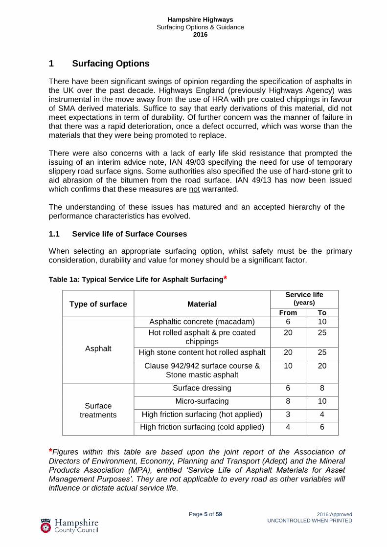
There have been significant swings of opinion regarding the specification of asphalts in the UK over the past decade. Highways England (previously Highways Agency) was instrumental in the move away from the use of HRA with pre coated chippings in favour of SMA derived materials. Suffice to say that early derivations of this material, did not meet expectations in term of durability. Of further concern was the manner of failure in that there was a rapid deterioration, once a defect occurred, which was worse than the materials that they were being promoted to replace. There were also concerns with a lack of early life skid resistance that prompted the issuing of an interim advice note, IAN 49/03 specifying the need for use of temporary slippery road surface signs. Some authorities also specified the use of hard-stone grit to aid abrasion of the bitumen from the road surface. IAN 49/13 has now been issued which confirms that these measures are not warranted. The understanding of these issues has matured and an accepted hierarchy of the performance characteristics has evolved. 1.1 Service life of Surface Courses When selecting an appropriate surfacing option, whilst safety must be the primary consideration, durability and value for money should be a significant factor.
Table 1a: Typical Service Life for Asphalt Surfacing*
*Figures within this table are based upon the joint report of the Association of
Directors of Environment, Economy, Planning and Transport (Adept) and the Mineral Products Association (MPA), entitled ‘Service Life of Asphalt Materials for Asset Management Purposes’. They are not applicable to every road as other variables will influence or dictate actual service life.
Type of surface
Material
Service life (years)
From To
Asphalt
Asphaltic concrete (macadam) 6 10
Hot rolled asphalt & pre coated chippings
20 25
High stone content hot rolled asphalt 20 25
Clause 942/942 surface course & Stone mastic asphalt
10 20
Surface treatments
Surface dressing 6 8
Micro-surfacing 8 10
High friction surfacing (hot applied) 3 4
High friction surfacing (cold applied) 4 6
Hampshire Highways
Surfacing Options & Guidance 2016
Page 6 of 59 2016:Approved
UNCONTROLLED WHEN PRINTED
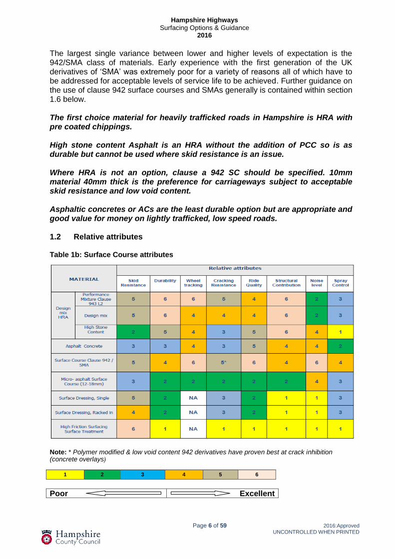
The largest single variance between lower and higher levels of expectation is the 942/SMA class of materials. Early experience with the first generation of the UK derivatives of ‘SMA’ was extremely poor for a variety of reasons all of which have to be addressed for acceptable levels of service life to be achieved. Further guidance on the use of clause 942 surface courses and SMAs generally is contained within section 1.6 below. The first choice material for heavily trafficked roads in Hampshire is HRA with pre coated chippings. High stone content Asphalt is an HRA without the addition of PCC so is as durable but cannot be used where skid resistance is an issue. Where HRA is not an option, clause a 942 SC should be specified. 10mm material 40mm thick is the preference for carriageways subject to acceptable skid resistance and low void content. Asphaltic concretes or ACs are the least durable option but are appropriate and good value for money on lightly trafficked, low speed roads. 1.2 Relative attributes Table 1b: Surface Course attributes
Note: * Polymer modified & low void content 942 derivatives have proven best at crack inhibition (concrete overlays)
Poor Excellent
1 2 3 4 5 6

Hampshire Highways
Surfacing Options & Guidance 2016
Page 7 of 59 2016:Approved
UNCONTROLLED WHEN PRINTED
Where a proposed option achieves a score of 2 or less careful consideration should be given to ensure that the relevant attribute is not important or relevant for the scheme in question. 1.3 Site Classification In order to provide consistency of approach in classifying sites, the following tables offer appropriate guidance. These tables should be referred to for selection of appropriate materials, dependent on speeds and traffic volumes. The notes for guidance that follow the tables are particularly useful if selection of a particular classification is not immediately obvious. Hampshire County Council’s approach on the monitoring of skid resistance is described in the document ‘HMMP Procedure - Skid Resistance, version 1.1’. There are a number of options for a site which has too low a level of skid resistance, including retexturing or reducing permitted speeds. A further option is to resurface with either asphalt or surface dressing, depending on the structural condition of the pavement. Where these are appropriate, the specification of the correct materials containing suitable aggregates is essential, not only in terms of achieving appropriate skid resistance but also durability which ultimately equates to value for money. Although surface texture (macro-texture) as achieved by adequate texture depth, is important in aiding good skid resistance, particularly at higher speeds, the micro-texture of the coarse aggregate as measured by the PSV has the greatest effect on skid resistance and safety in the wet. As the surface ages this becomes increasingly relevant. It is important to understand that there is growing demand for high PSV aggregates so ‘over specification’ should be avoided. Safety is the primary concern but this should not prevent a proper assessment of the risks on sites to avoid the unnecessary use of a diminishing resource. Proposals for use of alternative, often recycled aggregates should be favourably considered. There are aggregates currently in use e.g. Steel Slag that have been demonstrated to offer better skid resistance than would be expected from declared psv results. Any such proposals should only be supported if they are underpinned by robust, independent research. With PSV measurements a higher value indicates greater resistance to polishing and therefore a ‘high risk’ site would use higher PSV aggregate. For AAV the higher the figure quoted the more the stone abrades so a lower figure is more resistant to wear. The following tables are based on advice given in Highways Agency standard, HD 36 and amendment (IAN 156/12 Sept 2012). This advice note was written is based principally around the Highways England network and can be considered as ‘cautious’. In these tables the site categories and target skid resistance values, reflect the level of risk and the intensity of polishing that the aggregate will be subjected to, hence a higher number of commercial vehicles results in the specification of a higher psv. In the absence of specific growth figures the commercial traffic flow shall be estimated to increase at a rate of 2% per annum.
Hampshire Highways
Surfacing Options & Guidance 2016
Page 8 of 59 2016:Approved
UNCONTROLLED WHEN PRINTED
Tables 1e, 1f & 1g give guidance on the required properties for coarse aggregates whichever option is taken. As traffic speed is the key driver in the requirement for surface skid resistance, options are given on the basis of roads being above or below the threshold of the 85th percentile speeds of 40mph (64kph) This distinction is made due to the greater need for macro-texture at higher speeds where there is a greater risk of aquaplaning. HRA with chips is the first choice material for highly trafficked roads. However the laying of HRA and chippings requires sufficient width of carriageway to allow the chipping machine to be fed. As a general rule wherever the carriageway width is less than 6m it may be necessary to consider alternative materials. There are circumstances such as adjacent footpaths that can affect this, but anything below 6m will require consultation with the surfacing contractor. Where there are a high number of commercial vehicles, a resistance to rutting is to be specified. A performance mix HRA, clause 943 (level 2), should be specified. As an alternative 942 products whilst being less durable in terms of wear do achieve acceptable levels of rut resistance. For the 5 year guarantee included within clause 942 to be effective details of site layout, traffic volumes and speed must be provided to the contractor to allow them to propose the appropriate material. Guidance on the preferred surfacing materials and surface texture requirements are based on the combination of site category and projected commercial vehicle traffic flow at the design life (i.e. in 20 years time allowing for the projected growth rate) The 'Site Categories' as defined below are derived from HD36 in the Design Manual for Roads and Bridges (DMRB) with minor amendments applicable to County roads.

Hampshire Highways
Surfacing Options & Guidance 2016
Page 9 of 59 2016:Approved
UNCONTROLLED WHEN PRINTED
Table 1c: (a) Classification of Sites by Traffic and Stress Condition - Speed Limit 40mph or Greater
Road Hierarchy - COGP Category
4a + 4b 3a + 3b 2
Section
Site
Category (HD36)
Site Definition
Traffic Design Life (20 yr.) (Commercial vehicles per lane per day)
Up to 50 51- 500
501- 1000
1001- 1500
1500-2000
2001-2500
> 2500
a i C Estate Roads
a ii B Dual carriageway (non-event sections and minor junctions) HRA or 942 SC 943 HRA or 942 SC
a iii C Single carriageway (non-event sections and minor junctions) AC HRA or 942SC 943 HRA or 942 SC
a iv As above, but with slow moving traffic anticipated during summer months HRA or 942 SC 943 HRA or 942 SC
a v
Q1,Q2,Q3
G1
Approaches to and across major junctions (all limbs) Dual and single carriageways Gradient 5% to 10%, longer than 50m:
HRA or 942 SC
943 HRA or 942 SC
a vi As above, but with slow moving traffic anticipated during summer months or in a south-facing cutting HRA or 942 SC 943 HRA or 942 SC
a vii G2 Gradient steeper than 10%, longer than 50m: Dual and single carriageway
HRA or 942 SC 943 HRA or 942 SC
a viii R Roundabouts (including exits)
HRA
943 HRA
a ix As a vii, but with slow moving traffic anticipated during summer months or in a south-facing cutting
HRA or 942 SC
Less than 250 cvd per day
943 HRA or 942 SC
a x As a viii, but with slow moving traffic anticipated during summer months or in a south-facing cutting
HRA Less than 250 cvd per
day 943 HRA
a xi K Approach to roundabout, traffic signals pedestrian crossings, railway level crossings and similar features
HRA Less than 250 cvd per
day
943 HRA

Hampshire Highways
Surfacing Options & Guidance 2016
Page 10 of 59 2016:Approved
UNCONTROLLED WHEN PRINTED
General notes to table 1c: Speed Limit 40mph or Greater The above table represents permitted options; preference should be given to the option that represents the best value based on predicted service life unless there are scheme specific issues that justify alternative choice. Key:
AC = Asphalt Concrete 14mm or 10mm close graded. 942 SC = Stone mastic asphalt 6mm, 10mm or 14mm. HRA = Design mix, 4 to 8kn with 20mm pre coated or HSCA where
surface texture is not a consideration. 943 HRA = Performance design mix confirming to Level 2 wheel tracking resistance (60º test) requirements a i Shared service & residential roads serving up to 50 dwelling
These roads are unlikely to have a speed limit of 40mph or more so they are not covered. In the event that such a road is to be resurfaced, it should be considered against the most appropriate of the other site categories with consideration for inherent risks. a ii Dual carriageway (non-event sections and minor junctions)
This category will require a material resistant to deformation (rutting) and loss of surface texture. The preferred option is an HRA, on heavily trafficked sites traditional HRA is liable to rut and hence, a clause 943, asphalt should be specified. On lightly trafficked sites where rutting is unlikely to be an issue, then standard ‘design mix’ HRA is appropriate. A proprietary 942 surface course may be a second choice alternative if the laying of HRA is not practical. For HRA a 1.5mm surface texture shall be specified. Texture depths for 942 materials will be in accordance with IAN 154/12 (average 0.9mm – maximum 1.8, for 14mm nominal size aggregates & 0.8mm – maximum 1.6 for 10mm). a iii Single Carriageway (non-event sections and minor junctions)
The requirements for these sites are similar to those for dual carriageways. The exception being in the, ‘up to 50 cvd’ category where an AC or SMA surface course is an option if texture is not a requirement. For more highly stressed areas an HSCA could also be considered but as with the AC & SMA options, macro texture for this material is poor so it should not be used where macro texture is required. For HRA a 1.5mm surface texture shall be specified. Texture depths for 942 materials will be in accordance with IAN 154/12 (average 0.9mm – maximum 1.8, for 14mm nominal size aggregates & 0.8mm – maximum 1.6 for 10mm). a iv Dual or Single Carriageways (include. minor junctions) with slow-moving traffic anticipated during summer months In periods of hot weather road temperatures can cause the bitumen within asphalt to soften. Slow moving traffic results in intensified loading which can cause rutting and/or deformation, hence the requirement for specified levels of rut resistant performance. For HRA a 1.5mm surface texture shall be specified. Texture depths for 942 materials will be in accordance with IAN 154/12 (average 0.9mm – maximum 1.8, for 14mm nominal size aggregates & 0.8mm – maximum 1.6 for 10mm).
Hampshire Highways
Surfacing Options & Guidance 2016
Page 11 of 59 2016:Approved
UNCONTROLLED WHEN PRINTED
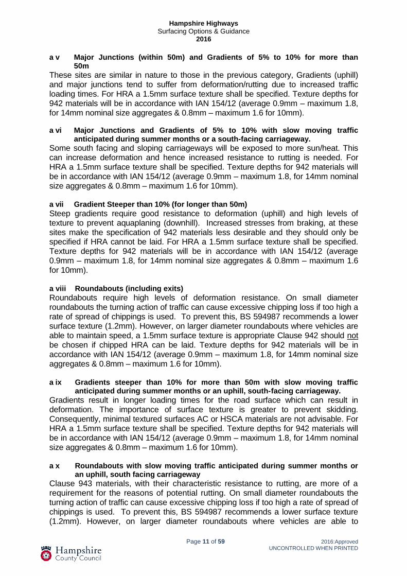
a v Major Junctions (within 50m) and Gradients of 5% to 10% for more than 50m
These sites are similar in nature to those in the previous category, Gradients (uphill) and major junctions tend to suffer from deformation/rutting due to increased traffic loading times. For HRA a 1.5mm surface texture shall be specified. Texture depths for 942 materials will be in accordance with IAN 154/12 (average 0.9mm – maximum 1.8, for 14mm nominal size aggregates & 0.8mm – maximum 1.6 for 10mm). a vi Major Junctions and Gradients of 5% to 10% with slow moving traffic anticipated during summer months or a south-facing carriageway.
Some south facing and sloping carriageways will be exposed to more sun/heat. This can increase deformation and hence increased resistance to rutting is needed. For HRA a 1.5mm surface texture shall be specified. Texture depths for 942 materials will be in accordance with IAN 154/12 (average 0.9mm – maximum 1.8, for 14mm nominal size aggregates & 0.8mm – maximum 1.6 for 10mm). a vii Gradient Steeper than 10% (for longer than 50m)
Steep gradients require good resistance to deformation (uphill) and high levels of texture to prevent aquaplaning (downhill). Increased stresses from braking, at these sites make the specification of 942 materials less desirable and they should only be specified if HRA cannot be laid. For HRA a 1.5mm surface texture shall be specified. Texture depths for 942 materials will be in accordance with IAN 154/12 (average 0.9mm – maximum 1.8, for 14mm nominal size aggregates & 0.8mm – maximum 1.6 for 10mm). a viii Roundabouts (including exits)
Roundabouts require high levels of deformation resistance. On small diameter roundabouts the turning action of traffic can cause excessive chipping loss if too high a rate of spread of chippings is used. To prevent this, BS 594987 recommends a lower surface texture (1.2mm). However, on larger diameter roundabouts where vehicles are able to maintain speed, a 1.5mm surface texture is appropriate Clause 942 should not be chosen if chipped HRA can be laid. Texture depths for 942 materials will be in accordance with IAN 154/12 (average 0.9mm – maximum 1.8, for 14mm nominal size aggregates & 0.8mm – maximum 1.6 for 10mm). a ix Gradients steeper than 10% for more than 50m with slow moving traffic anticipated during summer months or an uphill, south- facing carriageway.
Gradients result in longer loading times for the road surface which can result in deformation. The importance of surface texture is greater to prevent skidding. Consequently, minimal textured surfaces AC or HSCA materials are not advisable. For HRA a 1.5mm surface texture shall be specified. Texture depths for 942 materials will be in accordance with IAN 154/12 (average 0.9mm – maximum 1.8, for 14mm nominal size aggregates & 0.8mm – maximum 1.6 for 10mm). a x Roundabouts with slow moving traffic anticipated during summer months or an uphill, south facing carriageway
Clause 943 materials, with their characteristic resistance to rutting, are more of a requirement for the reasons of potential rutting. On small diameter roundabouts the turning action of traffic can cause excessive chipping loss if too high a rate of spread of chippings is used. To prevent this, BS 594987 recommends a lower surface texture (1.2mm). However, on larger diameter roundabouts where vehicles are able to

Hampshire Highways
Surfacing Options & Guidance 2016
Page 12 of 59 2016:Approved
UNCONTROLLED WHEN PRINTED
maintain speed, a 1.5mm surface texture is appropriate Clause 942 should not be chosen if a chipped HRA can be laid. Texture depths for 942 materials will be in accordance with IAN 154/12 (average 0.9mm – maximum 1.8, for 14mm nominal size aggregates & 0.8mm – maximum 1.6 for 10mm). a xi Approaches to Roundabouts, Traffic Signals, Pedestrian Crossings, Railway Level Crossings and similar features.
These are often subjected to extreme traffic forces. The continual braking and acceleration combined with long traffic loading times due to low speeds are likely to result in deformation. Any rutted material at a lower layer may need replacement for a 'long term' solution. If this is required the underlying material should also be selected on the basis of an ability to resist wheel tracking. For HRA a 1.5mm surface texture shall be specified. Clause 942 should not be chosen if a chipped HRA can be laid. Texture depths for 942 materials will be in accordance with IAN 154/12 (average 0.9mm – maximum 1.8, for 14mm nominal size aggregates & 0.8mm – maximum 1.6 for 10mm). Other Considerations; a xii Bends of Radius - 250m to 500
Bends of this type do not suffer 'structurally' from vehicle loading forces beyond the normal for the nature of the road. Consequently, the category can be as per the appropriate preceding classification. a xiii Bends of Radius - up to 250m
The guidance given for the preceding category is also valid for these tighter bends. Given the high braking stresses, a chipped HRA is preferable. Where visibility is poor or where there is a history of wet skid accidents additional measures may need to be considered. The PSV and AAV of the PCCs and coarse aggregates shall be specified in accordance with tables 1c, 1d, & 1e of this document.

Hampshire Highways
Surfacing Options & Guidance 2016
Page 13 of 59 2016:Approved
UNCONTROLLED WHEN PRINTED
Table 1d: (b) Classification of sites by traffic & stress condition - Speed limit less than 40mph
Road Hierarchy - COGP Category
4a + 4b 3a + 3b 2
Section
Site
Category (HD36)
Site Definition
Traffic Design Life (20 yrs.) (Commercial vehicles per lane per day)
Up to 50 51 - 500
501 – 1000
1001 - 1500
1500 - 2000
2001 - 2500
> 2500
b i C Estate Roads (level/straight) AC or 942SC
b ii C Estate Distributor Roads and Estate Roads with steep gradients or tight bends
AC or 942SC
b iii B Dual carriageway (non-event sections and minor junctions) HRA or 942 SC
HRA or 942 SC 943 HRA or 942 SC
b iv C Single carriageway (non-event sections and minor junctions) AC, HRA or
942 SC
b v Q1,Q2,Q3
R
Approaches to and across major junctions (all limbs) Roundabouts (including exits)
HRA 943 HRA
b vi G1 Gradient 5% to 10%, longer than 50m: Dual and single carriageways
HRA or 942 SC
943 HRA
b vii As b vi above, but in a south-facing cutting
HRA 943 HRA
b viii G2 Gradient steeper than 10%, longer than 50m: Dual and single carriageways
b ix As b viii above, but in a south-facing cutting HRA
943 HRA
b X K Approach to roundabout, traffic signals, pedestrian crossings, railway level crossings and similar features
HRA or 942
SC
943 HRA or 942 SC

Hampshire Highways
Surfacing Options & Guidance 2016
Page 14 of 59 2016:Approved
UNCONTROLLED WHEN PRINTED
General notes to table 1d: Speed limit less than 40mph
The above table represents permitted options; preference should be given to the option that represents the best value based on predicted service life unless there are scheme specific considerations that justify alternative choice
Key:
AC = Asphalt Concrete 14mm or 10mm close graded. 942 SC = Stone mastic asphalt 14mm or 10mm. HRA = Design mix 4 to 8kn with 20mm pre coated or HSCA where
surface texture is not a consideration. 943 HRA = Performance design mix confirming to Level 2 wheel tracking resistance (60º test) requirements b i Shared service & residential roads serving up to 50 properties, level/ straight
Most estate roads carry very few commercial vehicles. Consequently, an AC or SMA surface course is normally adequate for the loads imposed. Low vehicle speeds mean that only nominal surface texture is necessary. In the unlikely event that such a road is expected to carry more than 50 cvds by the end of the surfacing 'design life' then it should be considered to be within the most appropriate of the other site categories covered by this table. b ii Estate distributor roads and estate roads with steep gradients and/or tight bends
These sites are similar to those in b i, except that the gradients/bends make more texture than that given by a 6mm nominal size material desirable so where possible larger nominal size ACs or SMA should be considered. b iii Dual Carriageway (non-event and minor junctions)
Sites of this type require a material resistant to rutting but due to lower traffic speeds Surface texture is less important unless a history of skidding accidents. High Stone Content (HSC) asphalt is an option for sites carrying up to 500 cvd where no history of skidding accidents exists. 55/14 (14mm nominal size) material gives more texture than 55/10 (10mm) material but the latter is less liable to segregation during hand laying/raking. For HRA a 1.2mm surface texture shall be specified. Texture depths for 942 materials will be in accordance with IAN 154/12 (average 0.9mm – maximum 1.5, for 14mm or less nominal size aggregates) b iv Single Carriageways (non-event sections and minor junctions)
These sites are similar in terms of traffic stresses to those in b iii above and hence the same vehicle flow/material parameters have been used. For HRA a 1.2mm surface texture shall be specified. Texture depths for 942 materials will be in accordance with IAN 154/12 (average 0.9mm – maximum 1.5, for 14mm or less nominal size aggregates) b v Approaches to and across major junctions and roundabouts
At speeds below 40 mph these sites are similar in terms of the vehicle stresses. Additionally, roundabouts in areas with speed limits less than 40mph tend to be smaller and hence the lower surface texture level need be specified. For HRA a 1.2mm surface texture shall be specified. Texture depths for 942 materials will be in accordance with IAN 154/12 (average 0.9mm – maximum 1.5, for 14mm or less nominal size aggregates) b vi Gradient of 5% to 10% for more than 50m
As gradients can result in longer loading times, deformation can result. The requirement for surface texture is greater for sites with gradients to help prevent skidding. Surface

Hampshire Highways
Surfacing Options & Guidance 2016
Page 15 of 59 2016:Approved
UNCONTROLLED WHEN PRINTED
course with minimal macro texture (e.g. High Stone Content asphalt) are not appropriate. For HRA a 1.2mm surface texture shall be specified. Texture depths for 942 materials will be in accordance with IAN 154/12 (average 0.9mm – maximum 1.5, for 14mm or less nominal size aggregates) b vii Gradient of 5% to 10% for more than 50m on a south facing carriageway
A site where extra surface heat results from facing south makes deformation resistance more important. Minimal textured surfaces (e.g. High Stone Content asphalt) are not appropriate. For HRA a 1.2mm surface texture shall be specified. Texture depths for 942 materials will be in accordance with IAN 154/12 (average 0.9mm – maximum 1.5, for 14mm or less nominal size aggregates) b viii Gradients steeper than 10% for longer than 50m
Sites of this type require similar resistance to deformation to those in b vii above. The steeper nature of these sites makes texture micro and macro, very important despite traffic speeds below 40mph. For HRA a 1.2mm surface texture shall be specified. Texture depths for 942 materials will be in accordance with IAN 154/12 (average 0.9mm – maximum 1.5, for 14mm or less nominal size aggregates) b ix Gradients steeper than 10% more than 50m in a south facing carriageway
As b viii above but a slightly greater resistance to deformation is necessary due to the higher road temperatures commonly occurring in south facing carriageways. For HRA a 1.2mm surface texture shall be specified. Texture depths for 942 materials will be in accordance with IAN 154/12 (average 0.9mm – maximum 1.5, for 14mm or less nominal size aggregates) b x Approaches to roundabouts, traffic signals, pedestrian & railway level crossings and similar features
These sites are subjected to braking/acceleration forces and relatively long vehicle loading times. This will result in deformation. It is important to note on such sites that any rutted material at a lower layer may need replacement for a 'long term' solution. If this is required the underlying material should also be selected on the basis of their ability to resist wheel tracking. For HRA a 1.2mm surface texture shall be specified. Texture depths for 942 materials will be in accordance with IAN 154/12 (average 0.9mm – maximum 1.5, for 14mm or less nominal size aggregates) b xi Bends of Radius - less than 500m
At speeds below 50 mph bends of radius less than 500m are not considered as specific site categories. At such speeds there is little risk of aquaplaning and hence such sites should be designed to the most appropriate site category. However, where sites include bends of radius less than 100m, accident history and traffic flows will need to be taken into account as part of this exercise. For HRA a 1.2mm surface texture shall be specified. Texture depths for 942 materials will be in accordance with IAN 154/12 (average 0.9mm – maximum 1.5, for 14mm or less nominal size aggregates The PSV and AAV of the PCCs and coarse aggregates shall be specified in accordance with tables 1e, 1f, & 1g of this document.

Hampshire Highways
Surfacing Options & Guidance 2016
Page 16 of 59 2016:Approved
UNCONTROLLED WHEN PRINTED
1.4 Selection of surfacing aggregate Aggregate used in the production of asphalt shall be hard, durable and clean. It should be of a suitable shape and for trafficked surfaces, provide a level of skid resistance by virtue of surface roughness (micro texture). The following key characteristics are measured as follows
Hardness: Los Angeles coefficient (LA)
Durability: Aggregate abrasion value (AAV), Magnesium sulphate soundness value (MSSV), Water absorption (WA)
Cleanness: Sieve test (% less than 0.075mm)
Shape: Flakiness index (FI)
Micro texture: Polished stone value (PSV).
The physical requirements for aggregates are stated in BS EN 13043 and the associated guidance document PD 6682-2.
Limestone coarse aggregate is not currently permitted in any surface course materials. (Potentially 50+psv material may be proposed subject to acceptable trials).
Specification of Polished Stone Value (PSV) & Aggregate Abrasion Value (AAV): The tables below are extracts of IAN 156/12 & 56/06 respectively and should be used in conjunction with the following guidance: General: Except where stated otherwise in the specific guidance below, the higher levels of Target Skid Resistance (SFC) should only be specified where there is a known history of wet skid accidents showing a significantly higher level than the county average for that type of site. Site category K: Where approach speeds are slow and visibility is good the lowest target skid resistance should be used (0.50). For crossings in 40mph or greater zones, or where, for other reasons, heavy braking is anticipated the higher level should be used (0.55). Site category Q: For approaches to roundabouts (incl. mini roundabouts) and signals in zones of 40mph or less, approaches to junctions on major roads in 40mph zones and approaches to junctions on minor roads with any speed limit, the lowest figure should be used (0.45). For roundabouts, signal approaches and across junctions on major roads in 50mph or greater zones 0.50 should be used. Only where there are significantly higher risks should the highest level be applied (0.55) Site category R: Generally the lowest value should be used (0.45). However, where circulation speeds are high, where there is frequent use by cyclists and motorcyclists or where there is an absence of signalised control on grade-separated junctions, then higher level 0.55 is appropriate.

Hampshire Highways
Surfacing Options & Guidance 2016
Page 17 of 59 2016:Approved
UNCONTROLLED WHEN PRINTED
Site category S1: (Dual Carriageway bends). Where traffic needs to slow down to safely negotiate the bend, where there is adverse camber or where the road geometry presents an increased hazard and for bends on dual carriageways the target skid resistance should be raised to 0.50. Otherwise select the lower target skid resistance (0.45). Site Category S2: (Single Carriageway bends). The default target skid resistance of 0.50 should be lowered to 0.45 unless there is evidence that the bend has an enhanced accident risk. The highest target of 0.55 should be used only where a risk assessment identifies significantly enhanced risks such as adverse camber or very poor road geometry. Table 1e: Minimum PSV for chippings or coarse aggregate in bituminous surfacing (excluding clause 942 surface courses)
Site Description
Site Category
Investi
gato
ry
levels
Estimated commercial traffic flow at end of life of surface
( cv/lane/day)
0
250
251 500
501 750
751 1000
10012000
20013000
30014000
40015000
Over 5000
Dual Carriageways free flowing traffic, relatively straight line
B1
0.30 0.35 0.40
50 50 50
50 50 50
50 50 50
50 50 55
50 50 60
55 60 65
55 60 65
60 60 65
65 65 65
Dual Carriageways where some braking regularly occurs
B2
0.35 0.40
50 55
50 60
50 60
55 65
55 65
60 68+
60 68+
65 68+
65 68+
Single carriageways free flowing traffic, relatively straight line
C
0.35 0.40 0.45
50 55 60
50 60 60
50 60 65
55 65 65
55 65
68+
60 68+ 68+
60 68+ 68+
65 68+ 68+
65 68+ 68+
Gradients 5% - 10% Gradients > 10% As above – elevated risks
G1/G2
0.45 0.50 0.55
55 60
68+
60 68+ HFS
60 68+ HFS
65 HFS HFS
65 HFS HFS
68+ HFS HFS
68+ HFS HFS
68+ HFSHFS
68+ HFS HFS
Approaches to pedestrian crossings and other high risk situations.
K
0.50 0.55
65 68+
65 68+
65 HFS
68+ HFS
68+ HFS
68+ HFS
HFS HFS
HFS HFS
HFS HFS
Approaches to major and minor junctions on dual and single carriageways. Approaches to roundabouts.
Q
0.45 0.50 0.55
60 65
68+
65 65
68+
65 65
HFS
68+ 68+ HFS
68+ 68+ HFS
68+ 68+ HFS
68+ HFS HFS
68+ HFS HFS
68+ HFS HFS
Roundabout circulation areas and exits (incl. mini).
R
0.45 0.50
50 68+
55 68+
60 68+
60 68+
65 68+
65 68+
68+ 68+
68+ 68+
68+ 68+
Bends, radius less than 500m on all roads (50mph & above or with other hazards resulting in braking or cornering).
S1/S2
0.45 0.50 0.55
50 68+ HFS
55 68+ HFS
60 68+ HFS
60 HFS HFS
65 HFS HFS
65 HFS HFS
68+ HFS HFS
68+ HFS HFS
HFS HFS HFS

Hampshire Highways
Surfacing Options & Guidance 2016
Page 18 of 59 2016:Approved
UNCONTROLLED WHEN PRINTED
Table 1f: Minimum PSV for coarse aggregate in clause 942 surface courses
Site Description
Site Category
Investi
gato
ry
levels
Estimated commercial traffic flow at end of life of surface
( cv/lane/day)
0
250
251 500
501 750
751
1000
1001 2000
2001 3000
3001 4000
4001 5000
Over 5000
Dual Carriageways free flowing traffic, relatively straight line
B1
0.30 0.35 0.40
50 50 50
50 50 50
50 50 50
50 50 50
50 50 53
50 53 58
50 53 58
53 53 58
63 63 63
Dual Carriageways where some braking regularly occurs
B2
0.35 0.40
50 55
50 60
50 60
55 65
55 65
60 68+
60 68+
65 68+
65 68+
Single carriageways free flowing traffic, relatively straight line
C
0.35 0.40 0.45
50 50 53
50 53 53
50 53 58
50 58 58
50 58 63
53 63 63
53 63 63
58 63 63
63 68+ 68+
Gradients 5% - 10% Gradients > 10% As above elevated risks
G1/G2
0.45 0.50 0.55
55 60
68+
60 68+ HFS
60 68+ HFS
65 HFS HFS
65 HFS HFS
68+ HFS HFS
68+ HFS HFS
68+ HFS HFS
68+ HFS HFS
Approaches to pedestrian crossings and other high risk situations.
K
0.50 0.55
65 68+
65 68+
65 HFS
68+ HFS
68+ HFS
68+ HFS
HFS HFS
HFS HFS
HFS HFS
Approaches to major and minor junctions on dual and single carriageways. Approaches to roundabouts.
Q
0.45 0.50 0.55
60 65
68+
65 65
68+
65 65
HFS
68+ 68+ HFS
68+ 68+ HFS
68+ 68+ HFS
68+ HFS HFS
68+ HFS HFS
68+ HFS HFS
Roundabout circulation areas and exits (incl. mini).
R
0.45 0.50
50 68+
55 68+
60 68+
60 68+
65 68+
65 68+
68+ 68+
68+ 68+
68+ 68+
Bends, radius less than 500m on all roads (50mph & above or with other hazards resulting in braking or cornering).
S1/S2
0.45 0.50 0.55
50 68+ HFS
55 68+ HFS
60 68+ HFS
60 HFS HFS
65 HFS HFS
65 HFS HFS
68+ HFS HFS
68+ HFS HFS
HFS HFS HFS
Hampshire Highways
Surfacing Options & Guidance 2016
Page 19 of 59 2016:Approved
UNCONTROLLED WHEN PRINTED
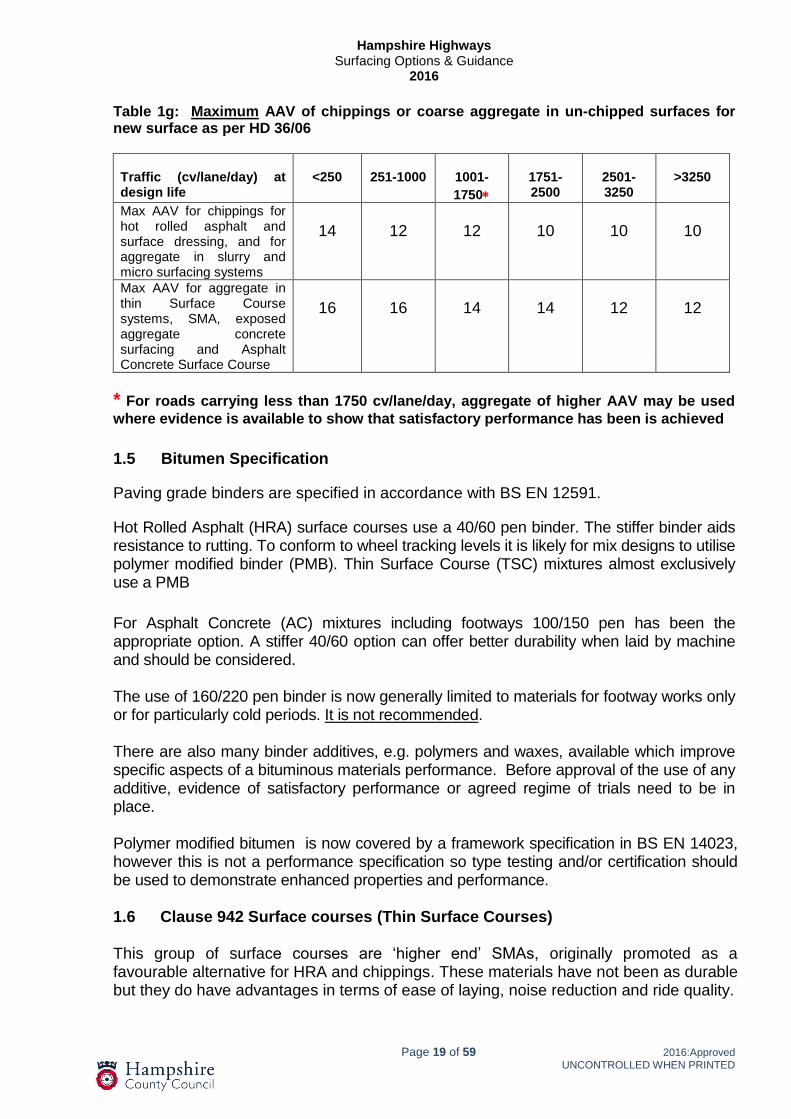
Table 1g: Maximum AAV of chippings or coarse aggregate in un-chipped surfaces for new surface as per HD 36/06 Traffic (cv/lane/day) at design life
<250
251-1000
1001-
1750
1751-2500
2501-3250
>3250
Max AAV for chippings for hot rolled asphalt and surface dressing, and for aggregate in slurry and micro surfacing systems
14
12
12
10
10
10
Max AAV for aggregate in thin Surface Course systems, SMA, exposed aggregate concrete surfacing and Asphalt Concrete Surface Course
16
16
14
14
12
12
* For roads carrying less than 1750 cv/lane/day, aggregate of higher AAV may be used
where evidence is available to show that satisfactory performance has been is achieved
1.5 Bitumen Specification
Paving grade binders are specified in accordance with BS EN 12591.
Hot Rolled Asphalt (HRA) surface courses use a 40/60 pen binder. The stiffer binder aids resistance to rutting. To conform to wheel tracking levels it is likely for mix designs to utilise polymer modified binder (PMB). Thin Surface Course (TSC) mixtures almost exclusively use a PMB
For Asphalt Concrete (AC) mixtures including footways 100/150 pen has been the appropriate option. A stiffer 40/60 option can offer better durability when laid by machine and should be considered. The use of 160/220 pen binder is now generally limited to materials for footway works only or for particularly cold periods. It is not recommended. There are also many binder additives, e.g. polymers and waxes, available which improve specific aspects of a bituminous materials performance. Before approval of the use of any additive, evidence of satisfactory performance or agreed regime of trials need to be in place. Polymer modified bitumen is now covered by a framework specification in BS EN 14023, however this is not a performance specification so type testing and/or certification should be used to demonstrate enhanced properties and performance. 1.6 Clause 942 Surface courses (Thin Surface Courses) This group of surface courses are ‘higher end’ SMAs, originally promoted as a favourable alternative for HRA and chippings. These materials have not been as durable but they do have advantages in terms of ease of laying, noise reduction and ride quality.

Hampshire Highways
Surfacing Options & Guidance 2016
Page 20 of 59 2016:Approved
UNCONTROLLED WHEN PRINTED
BBA certificates will indicate which class any particular material falls into and sets out any limitations as to use e.g. traffic loadings, temperature/general weather constraints, etc.;
Type C Thin Surface Course - products laid 26mm to 50mm thick
Type B Thin Surface Course - products laid 18mm to 25mm thick*
Type A Thin Surface Course - products laid 12mm to 18mm thick *
* Type A or B TSC materials are not used in HCC due to poor durability.
BBA certificate to check approval is still current and to ensure any restrictions on use/application are obeyed. Certificates are downloadable from www.bbacerts.co.uk. HAPAS approval allows manufacturers to substitute constituents within approved mixes, principally coarse aggregate. If the material proposed differs in any way from those detailed in the certificate, engineers should request information that demonstrates performance will not be compromised, More details can be found within IAN 157/11 2011. These proprietary products carry a five year guarantee period subject to sufficient information being made available to the supplier to enable them to supply an appropriate product.
1.7 Traffic noise considerations
The implication of an increase in road traffic noise could be a consideration for certain sites. The introduction of the Environmental Noise (England) Regulations in 2006 resulted in plans being developed to manage and reduce environmental noise generally. Defra has provided a framework to support transport authorities in the investigation and, treatment of ‘Important Areas’ by publishing the second round of ‘Noise Action Plans’. A small number of major road sites in Hampshire have been flagged as “first priority locations” with a view to the possible implementation of noise mitigation measures. These first priority locations are shown on maps via the Defra link: http://webarchive.nationalarchives.gov.uk/20130123162956/http://www.defra.gov.uk/environment/quality/noise/environmental-noise/action-plans/
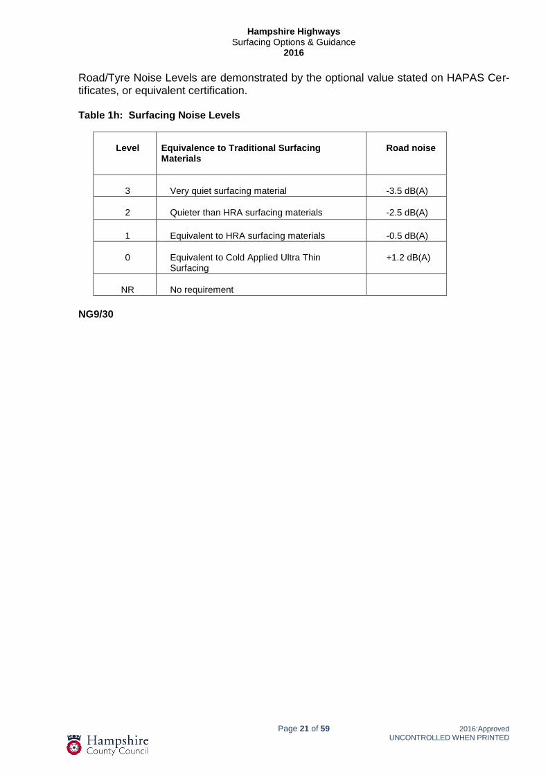
If it is necessary to specify a surfacing material to a given noise level care should be taken that this is balanced appropriately against cost and durability. Permitted Road/Tyre noise levels are given in Table NG9/30 below. Levels 2 and 3 are necessary in noise-sensitive areas. In the interest of sustainability, Level 3 should only be specified in very noise sensitive areas. Level 0 must not be specified at sites where existing noise barriers or earth bunds have been installed as a noise mitigation measure or at locations that have been identified as an Important Area, in any of England’s Noise Action Plans published by DEFRA.
Hampshire Highways
Surfacing Options & Guidance 2016
Page 21 of 59 2016:Approved
UNCONTROLLED WHEN PRINTED
Road/Tyre Noise Levels are demonstrated by the optional value stated on HAPAS Cer-tificates, or equivalent certification. Table 1h: Surfacing Noise Levels
Level
Equivalence to Traditional Surfacing Materials
Road noise
3
Very quiet surfacing material
-3.5 dB(A)
2
Quieter than HRA surfacing materials
-2.5 dB(A)
1
Equivalent to HRA surfacing materials
-0.5 dB(A)
0
Equivalent to Cold Applied Ultra Thin Surfacing
+1.2 dB(A)
NR
No requirement
NG9/30

Hampshire Highways
Surfacing Options & Guidance 2016
Page 22 of 59 2016:Approved
UNCONTROLLED WHEN PRINTED
2 General Guidance Until recently asphalt surface course was referred to as ‘wearing course’; this title reflected the fact that the top layer of asphalt was likely not to last as long as the underlying pavement. However if basic principles of pavement maintenance are not adhered to, the pavements structural life will be compromised and more substantial maintenance or even reconstruction will be required. Routinely the most common option for resurfacing consists of the replacement or covering of the existing surface course and the first step is to assess the condition of the existing road surface and the supporting foundation. The ‘basics’ of pavement construction remain unaltered since the time of the Romans:
The base should be sound and dry. The road, including sub-base foundation, should be thick enough to suffi-
ciently dissipate the loading applied to avoid damage or deformation to the underlying formation or sub-grade.
All layers of the pavement, including the formation should be well drained. Moisture should be prevented from permeating through the pavement.
From a maintenance perspective it is not always easy to address the first two of the above issues as options are restricted by the original design. There are occasions when, on engineering grounds it may be desirable to reconstruct a highway but considerations of disruption and cost, effectively rule it out. This document provides a pragmatic interpretation of current standards and the specification’s referred to below. There are a number of commonly encountered issues that are not addressed in any of those documents, for which solutions have been developed, based on experience and research. Given the size of the Hampshire network it is important to prioritise maintenance spend effectively. Unless a robust system exists to identify and prioritise which sections of carriageway are in need of work, limited funds will be spent ineffectively. The best value for money is achieved by assessing the cost of resurfacing against the cost of numerous less expensive interventions (patching, joint-sealing etc.). Included in the assessment of the need for resurfacing, there should be consideration of the increased risk of accidents as more defects occur, especially on high speed roads with an increased likelihood of serious or fatal accidents. Numerous drivers exist that necessitate resurfacing works. Safety is the key consideration when assessing if a carriageway needs treatment. Whilst individual defects such as potholes often have to be repaired as small patches, the management of the pavement asset is a fine balance between obtaining the maximum life out of the surfacing and reducing maintenance costs which are poor value for money if they become too frequent or are ineffective. Where there is justification to patch or repair small defects, maximum value is achieved by adopting best practice. The cost of numerous poorly undertaken repairs soon outweighs the marginally increased cost of undertaking a repair to the appropriate standards.
Hampshire Highways
Surfacing Options & Guidance 2016
Page 23 of 59 2016:Approved
UNCONTROLLED WHEN PRINTED
There are occasions when it is appropriate to respond to ‘emergency’ situations using temporary repair techniques but these are inherently wasteful so should be restricted to genuine emergencies. Any surfacing or surface treatment is only as good as the base upon which it is laid. The surface upon which any resurfacing is to take place should be sound, clean and dry. Before resurfacing, the condition of the existing pavement should be considered carefully and the new material specified accordingly. Sufficient investigation or testing should be carried out to establish the extent of existing defects. Many county roads have evolved over time and are not constructed to modern standards; they are often thin and exhibit more flexibility than a modern designed carriageway. New surfacing materials need to be able to accommodate this movement, if they are to provide a durable surface. It is essential that evolved highways are sealed effectively to prevent deterioration. Surface courses are not impervious, although HRAs are significantly less permeable than ACs, but where there is little depth of construction, additional waterproofing measures such as a binder course or a thick bond coat, must be considered. Water penetration through new surface course will cause the underlying formation to soften, leading to premature failure. Where and whenever formation or subgrade is exposed it is essential that due consideration is given to its protection from weather and/or site traffic during construction. 2.1 Relevant Specifications Works to construct, reconstruct or resurface roads have standards and specifications set out within the suite of documents as published by the Department of Transport, i.e. Standards for Highways. These include The Design Manual for Roads and Bridges (DMRB), The Manual of Contract Documents for Highway Works (MCHW), and Interim Advice Notes (IANs) which are routinely used to issue amendments before a formal redrafting of a specification. The most relevant sections of this document are;
Series 700: Road Pavements, General Series 800: Road Pavements, Unbound, Cement & Other Hydraulically Bound Mixtures Series 900: Road Pavement – Bituminous Bound Materials
The production, transportation and laying of asphalt materials are addressed in detail within European and British Standards. The old British Standards, BS594 (Hot Rolled Asphalt) and BS4987 (Coated Macadam), were superseded by the new EU standard, BS EN 13108. This series of documents did not deal with the laying of asphalt, as had its predecessors and as a result it has been added to by the publication of the unimaginatively titled BS594987. The new EN ‘harmonised’ standard, was further added to by the publication of PD (published document) 6691, which gives guidance on the use of BS EN13108.

Hampshire Highways
Surfacing Options & Guidance 2016
Page 24 of 59 2016:Approved
UNCONTROLLED WHEN PRINTED
BS EN 13108 = the product standard for Asphalt PD 6691: 2015 = guidance on choices for the mixtures most commonly
used in the UK BS594987: 2015 = the standard for the transportation & laying of asphalt. For new construction, areas of full depth reconstruction and general pavement design the relevant documents are:
DMRB Volume 7 HD 24/06 Traffic assessment = the method for the estimation and calculation of traffic loading for the design of road pavements. Design aids are provided for easy determination of the number of standard axles for use in the pavement design standard HD 26 (DMRB 7.2.3).
IAN 73/06 Rev 1 = (Draft of HD25) design guidance for road pavement founda-tions adding around 20% to the thickness of subbase based upon Highways Agency input.
DMRB Volume 7 HD26/06 Pavement design = the details of permitted materi-als and design thickness for the construction of pavements for new trunk roads. This revision updates the previous standard and introduces different permitted designs that relate to the strength of the available foundation.
This document assumes a basic understanding of the above standards, referral to which is advisable in many instances. However the evolved nature of the Hampshire highway network means a fair degree of interpretation and pragmatism is needed.
2.2 Common Defects
A basic understanding of the most prevalent defects assists in assessing effective solu-tions. Commonality in the description of defects is also helpful comparing and prioritis-ing potential sites.
Potholes – “a depression or hollow in a road surface caused by wear or subsid-ence”. A generic term used to describe a failure within the surface course of a pavement that may be caused by a host of factors, most commonly, worn out surface course. This wear is greatly accelerated by poor material choice or workmanship during installation.
Fretting or Ravelling – This is the disintegration of the surface course due to the larger aggregate within the material breaking away from the general matrix. This is particularly a problem with early generation SMAs, where the degeneration of the surface course accelerates rapidly around small defects. This is also com-mon with longitudinal joints, especially if poorly formed or sealed during construc-tion.
Delamination – To perform to its potential, a flexible pavement should act as a homogenous mass and the adhesion of layers and sealing against the ingress of water is essential. Delamination manifests itself in large potholes to the depth of the surface course where the surface course de-bonds from the underlying pavement and fractures causing the breakup of the top surface. Improvements in

Hampshire Highways
Surfacing Options & Guidance 2016
Page 25 of 59 2016:Approved
UNCONTROLLED WHEN PRINTED
the use of tanker applied bond coats as opposed to hand-applied tack-coat should reduce the likelihood of delamination considerably..
Reflective Cracking – Is a common fault where a rigid foundation has been overlaid with flexible surfacing. Rigid pavements should be either continuously reinforced with induced cracks or cast in slabs linked by dowel bars to allow for movement. When flexible surfacing is placed on this type of road it is unable to flex sufficiently to resist cracking.
Alligator Cracking – The failure of underlying layers (usually formation) mani-fests itself by the top surface continuing to adhere to the underlying layer but be-ing unable to flex sufficiently to resist cracking. This usually indicates a significant structural fault within the underlying foundation. In severe cases moisture can be seen to have been forced upwards through the surfacing; a clear sign that resur-facing alone is unlikely to be successful.
Loss of Surface Texture/Skid Resistance – Usually assessed by mechanical survey, the texture loss can be attributed to the polishing of the coarse aggre-gates (micro texture) or by a reduction in the surface voids/irregularity (macro texture), both of which are usually associated with wear by heavy trafficking. A loss of texture can also be caused by materials ‘fatting’ up, when bitumen is flushed to the surface, filling surface voids and covering coarse aggregates. This is more prevalent in hot weather.
Deformation – Poorly constructed roads either designed for smaller volumes of traffic or to less demanding standards often deform without actually breaking up. This is common on estate roads where a thin crust of asphalt may have been overlaid with one or more surface dressings which have remained flexible enough to move without cracking. In the case of thicker pavements, softer bind-ers used in older base (binder) courses and road base (base) layers have de-formed over time. In the most dramatic cases, subsidence or lateral movement in the underlying sub soils may cause surface deformation.
Rutting – It is sometimes difficult to distinguish from deformation but rutting is the formation of pronounced longitudinal depressions in the line of wheel tracks. In severe cases this leads to noticeable channels, which can hold water and cre-ate significant hazards. Rutting on the trunk road network was a significant driver towards the Highways Agency’s decision to drop HRA in favour of Thin Surface Courses.
Structural Failure – Wherever there is a failure throughout the depth of the pavement, then the failure is structural. In localised examples a crack or soft area can be treated individually but where the failure is extensive it is an indication that reconstruction rather than resurfacing is appropriate.
2.3 Inlay or Overlay
As a basic principle overlaying the existing surface is a cheaper and less invasive option than inlay. The removal of existing surfacing material is expensive, time consuming and environmentally unsound; if it can be avoided it should be.

Hampshire Highways
Surfacing Options & Guidance 2016
Page 26 of 59 2016:Approved
UNCONTROLLED WHEN PRINTED
Inlay is most effective for roads where the removal of the surface and in some cases binder courses, leaves a sound layer capable of supporting the new layers. If however new surface course is laid over an existing surface that is failed or failing the new material will not last and will represent poor value for money. It is therefore important to properly assess the options. These are the basic advantages of opting for an overlay;
Cost, duration and environmental impact are all reduced by the reduction or remov-al of planing operations.
Reduced risk of encountering poor underlying ground conditions
In cases where tar binder exists it is possible to negate the requirement to remove or process this hazardous material
For evolved roads, overlay increases the overall structural integrity of the pavement. Sites that are kerbed, or contain numerous entrances to properties will need to be carefully reviewed for suitability for an overlay as to retain access at existing levels will require planing. This can effect the existing long or cross profile of the road. Careful consideration must be given to avoid this causing standing water. Manhole and drainage covers and frames will need adjustment which can offset other advantages of the overlay option. Where overlay is decided upon the detail to ‘tie-in’ to the existing levels should also be properly defined. An effective tie-in will ensure the full depth of the surface layer can properly abut the existing surface material where it is sound. The length of the ‘tie in’ should be sufficient to provide a smooth alignment. Where a road is kerbed or there are numerous entrances, channel planing can be an option. This is equivalent to forming a longitudinal tie-in. Care must be taken, especially on narrow roads that planing along the edge or edges of the existing road does not accentuate the camber or cross-fall of a road to the point it is excessive. Once the decision that an inlay is appropriate has been made, it is necessary to assess if the removal and replacement of only the surface course will be sufficient. Surface courses, whilst having various degrees of durability, flexibility and imperviousness are formally not a significant factor in adding strength to a full depth, flexible pavement structure. However evolved county roads do rely to a significant extent, upon the strength of the surface course as by definition the underlying structure is not designed, so durability of a surface course is an important factor. 2.4 Depth of Treatment As a part of the design process, core samples should be taken through bound layers at sufficient spacing to form a representative picture of the thickness and type of the pavement. These samples will inform the design process by confirming the condition of

Hampshire Highways
Surfacing Options & Guidance 2016
Page 27 of 59 2016:Approved
UNCONTROLLED WHEN PRINTED
underlying layers. The cores can also identify the presence of tar and provide a sample for analysis. On evolved roads removal of the existing surface course can be akin to reconstruction as there is little structural substance beneath the removed layers. More investigation will be required to assess if the foundation is suitable. This will be by means of trial holes to allow an appropriate assessment of the condition of the existing formation to be made: The Drop Weight Penetrometer (DWP) or Dynamic Cone Penetrometer (DCP) can be used to provide this information. Care should be taken in the interpretation of results if these are undertaken through cores holes as the small area of formation or sub formation exposed may not be representative. Whilst core samples provide verification of the condition and make up of the existing pavement they do not provide information regarding the under laying foundation. Information should be obtained to establish the condition and suitability of the foundation to withstand traffic levels and also to be suitable for the construction process. See extract from the DMRB:
“It is expected that loads will be applied to the foundation by delivery vehicles, pavers and other construction plant. At any level where such loading is applied, the strength and material thickness have to be sufficient to withstand the load without damage occurring that might adversely influence, to any significant extent, the future performance of the pavement capping & sub-base design”.
It is inadvisable to remove existing bound layers and attempt to replace them without confidence in the ability of the underlying foundation to withstand the construction process.
For an inlay option it may be necessary to replace more than the surface course. The nature of the defects that are apparent from a good visual inspection will normally indicate if there is some deeper failure within the pavement. Typically binder courses are 50mm to 60mm nominal thickness when laid, beneath a 40mm to 45mm surface course. If defects are deeper than these layers (except in isolated areas) then the pavement requires reconstruction rather that resurfacing for which the standards and specifications within the MCDHW & HCC’s MCD are appropriate. Defects associated with surface course failure only, are ravelling (often associated with failing joints), potholes or stripping of coarse aggregates be that pre-coated or surface dressing chippings, or coarse aggregate from the surface courses layers. Some surfaces, with varying degrees of wear, loose texture and become less resistant to skidding.
Cracks can be reflective of underlying construction joints. This is prevalent with composite pavements. Whilst the cracks should be sealed to prevent the ingress of water, deeper treatment is unlikely to be justified unless there is evidence that the base layer has failed.
Deeper cracks or failures within pavement structural layers tend to lead to more random cracking, often with evidence of water pumping through the crack.

Hampshire Highways
Surfacing Options & Guidance 2016
Page 28 of 59 2016:Approved
UNCONTROLLED WHEN PRINTED
If fully flexible pavements crack significantly it is likely that there is a major structural failure which resurfacing alone is unlikely to resolve. As a general rule cracks through rigid pavements can be sealed if the slabs are sound and not rocking. Within a flexible or bituminous pavement, cracks tend to seriously reduce the pavements load bearing performance and will develop into larger defects. In such cases it is probable that reconstruction will be required.
On poor quality estate roads or rural evolved roads, where the surface appears randomly cracked in a tight matrix (alligator cracking), it is usually caused by the surface layer failing to flex sufficiently to resist cracking as the underlying road deflects under load. As referred to above the risk that the underlying foundation is inadequate for construction traffic or predicted traffic flows should be considered and addressed. To strip off the surface course and trust to fate that the underlying layer is fit for purpose when it comes to machine laying the new material is a poor option as costs and timescales quickly escalate. Appropriate investigation, trial holes and cores are essential to properly assess what works are appropriate and to check for the presence of tar bound materials. It can be difficult to establish the extent of rutting. Whether it exists within one or more layers of the pavement is not always clear from visual inspection or even coring but as a general rule, plastic upward heave at the rut’s edges suggest surface course failure whereas a downward rut only suggests displacement and failure within underlying layers.
HRA as a material type, especially those made with softer penetration grade binders is particularly susceptible to rutting. This was a major driver in the Highway Agency (Highways England) choice to move towards thin surface courses; however, whilst rutting in extreme situations can be considered dangerous, less dramatic deformation is not likely to require emergency repairs or develop into dangerous defects. Rutting tends to progress steadily, although the rate of increase accelerates during prolonged spells of hot weather.
It is important to understand the thickness of the existing pavement and the condition of the foundation upon which the bound layer(s) sits. As discussed earlier the evolved nature of a county highway network means that a large amount of the roads requiring maintenance could not be classed as ‘designed’. Cores will provide detail of the thickness and type of the bound layers but trial holes and other tests may also be worthwhile to establish the strength and suitability of what lies beneath.
2.5 Planing
When specifying planing for a full inlay or channel planing it is important to understand various aspects of the planing process;
Planing widths range from 350mm to 2.2m
Planers are usually fitted with elevators that remove the broken material into the
back of a lorry leaving a ridged surface that requires sweeping by mechanical sweeper before surfacing can commence.
Hampshire Highways
Surfacing Options & Guidance 2016
Page 29 of 59 2016:Approved
UNCONTROLLED WHEN PRINTED
Bituminous planings are a saleable commodity and traditionally are sold as a ma-terial suitable for tracks or hardened parking areas. The SHW now identifies a range of acceptable uses including as RAP (recycled asphalt pavement) for in-corporation in hot mix asphalts.
Modern planers work with electronic sensors and are usually accurate to around
±5mm.
Bigger machines can plane at up to 250mm in a single pass for typical bitumi-nous materials.
Planing allows for the removal and disposal of bituminous surfacing material only. Any underlying granular material or soils should be measured and billed as excavation and disposal of unsuitable material. Planing of concrete is not included for within normal planing rates. Specialist advice should be sought if the planing of concrete is being considered as this is can be time and cost prohibitive. If sites are to be opened for public use, vehicle or pedestrian, between planing and resurfacing, all joints, covers and other hazards need to properly ramped and signed using deferred set material. (See section 2.12) Tar Bound Planings - The Environment Agency takes the view that all arisings from construction processes should be classed as waste. As such anyone carrying these ma-terials, recycling them, or reprocessing them, must possess appropriate permits and li-censes.
“If you have waste you have a legal 'Duty of Care'. The Duty of Care applies to everyone involved in handling the waste: from the person who produces it to the person who finally disposes of or recovers it.”
Planings should be the categorised in accordance with the ‘List of Wastes’ (also known as the European Waste catalogue, EWC). This is essentially a list of descriptions of waste from various sources. Planings fall within the 17 03 category which has three sub divisions 01, 02 & 03. Two of these are hazardous waste, 17 03 03 and 17 03 01. 17 03 03 is an absolute hazard-ous waste code that is used whenever tar is present. 17 03 02 is the appropriate code for the bituminous planings. As tar is classed as a category 1 carcinogen it must not be present at a concentration greater than or equal to 0.1% (1000 mg/kg). The Environment Agency considers that if benzo(a)pyrene is present at a concentration of 50 mg/kg or more, the waste is EWC code 17 03 01. There is data corroborating this assertion that 50mg/Kg of benzopyrene correlates to around 1000mg/kg road tar.
Formerly such materials were disposed of to tips authorised to handle hazardous wastes at considerable cost. HCC have worked with partners to offset these costs by the development of a facility at Micheldever Depot to reprocess tar bound materials into a variety of products for reuse on the network

Hampshire Highways
Surfacing Options & Guidance 2016
Page 30 of 59 2016:Approved
UNCONTROLLED WHEN PRINTED
2.6 Layer thicknesses and weather All material thicknesses and laying temperatures shall be in accordance with the requirements of BS 594987 2015 or the appropriate BBA HAPAS Certificate applicable to proprietary materials. The requirements for wind speed and air temperatures in Clause 945 of the SHW (Specification for Highway Works) should be adhered to whenever bituminous materials are laid. Failure to do so adversely affects material compaction and chipping embedment. In the event that materials are laid outside of these requirements then liability for premature failure rests with the contractor (see Table 2a, below for guidance). Increases in layer thicknesses may be beneficial if laying materials in periods of cold weather to assist heat retention which in turn assists compaction.
The laying of chipped HRA surface courses in cold weather causes problems with workability and chipping embedment. The preferred thickness for HRA surfacing in Hampshire is 45mm, but this does not overcome these issues. Unless other circumstances dictate the laying of chipped HRA surface courses should be avoided during the months of November through to the end of February. Close attention to weather forecasts and communications between laying gangs and suppliers is essential. Modified binders can be used to improve the 'cold weather working' properties of some asphalts. Proprietary products can also have specific requirements regarding ambient temperatures which should be adhered to. Freshly laid materials being by nature dark will absorb more solar radiation than existing ‘weathered’ surfaces. In periods of hot weather asphalts will take significantly longer to cool and should not be subjected to loading by public or site traffic as these are likely to result in the surface become overly binder rich (fatting) and/or deformation. For similar reasons the planning of resurfacing works should make allowance for time for layers to cool. It is rarely possible to lay more than two layers in a single shift as with each successive layer the heat retention is increased and significantly slows the cooling of underlying layers. Low temperature asphalts are a new development and are referred to in more detail at 3.2 below. Table 2a: Asphalt Temperatures
Materials
For specifc minimum temperatures for materials reference
should be made to BS595987Rolling
Max Min Min
H.R.A. WEARING COURSES (50 PEN) 190 140 85
H.R.A. WEARING COURSES (50 PEN) with PCCS 190 155 85
H.R.A. BASECOURSE/ROADBASES(50 PEN) 170 120 85
DENSE/CLOSE GRADED MACADAMS (100 PEN) 160 120 95
DENSE/CLOSE GRADED MACADAMS (200 PEN) 150 110 85
Material Delivery
Temperatures ( º C)
Hampshire Highways
Surfacing Options & Guidance 2016
Page 31 of 59 2016:Approved
UNCONTROLLED WHEN PRINTED
2.7 Reinstatement around Utility Covers It is desirable that ironwork is raised before surfacing work is undertaken to enable the machine laid surface course to butt up against the frame in question. This provides a better ride quality and appearance. By raising ironwork before surfacing no patching is needed and this reduces the likelihood of premature failure around the cover and frame. If, for whatever reason, ironwork cannot be raised until after surfacing has been completed, consideration should be given to the process of reinstatement with the use of a hot rolled asphalt and adequate painting of all vertical faces. Proprietary systems also exist and whilst these are more costly, they are usually more durable and generally successful.
2.8 Bond Coats
There has been an increased understanding of the importance of a good bond between pavement layers and this has lead to a number of developments of the specification over recent years
‘The use of tack coats is no longer regarded as best practice’. PD6691:2015 annex J
Bond coats have higher binder contents than the traditional K1 40 tack coat which they have replaced. The bitumen is very often polymer modified or a harder grade of bitu-men, and is usually applied hot. All bond coats used in this country are cationic (as opposed to anionic) as these are more effective given that the positively charged emulsifiers react with the negatively charged aggregate surface to break more effectively.
As the use of bond coats have increased it is now sold in smaller quantities as well as in bulk. Therefore, bond coat in accordance with BS EN 13808 should be used for all resurfacing, patching or hand lay including between all bound layers. The Specification for Highway Works also now requires bond coats to be applied by a metered spray tanker whenever practical. Only in genuinely inaccessible areas should hand sprayers be permitted as an alternative. Pavers with integrated spray tanks offer the benefit of applying bond coat directly in front of paving preventing bond coat being removed by delivery vehicles which is beneficial and should be encouraged. The rate at which bond coat is to be applied is now given as a measure of the residual bitumen left after the emulsion has broken i.e. the water has evaporated. Bond coats are denominated using the following four factors;
C or A for Cationic or anionic – UK bond coats are almost exclusively cationic
Nominal binder content as a %
Type of binder: B = paving grade bitumen, P = polymer added, F more than 2% of fluxing agent.
Breaking behaviour, classes 1 to 7. Most available bond coats in this country fall into categories 3 to 4 (1 is the highest category and 7 the lowest)

Hampshire Highways
Surfacing Options & Guidance 2016
Page 32 of 59 2016:Approved
UNCONTROLLED WHEN PRINTED
Therefor a typical Bond coat could be described thus: C 50 BP 3 with the percentage of bitumen shown as 50%. BS594987 2015 specifies that the rate of spread of bond coat shall be at least 0.35 kg/m² of residual binder for planed surfaces and at least 0.20 kg/m2 when laid on to new binder course or existing asphalt. Certain proprietary products (clause 942 surface courses especially) will contain a specified rate of spread on the BBA certification. In county scenarios the specified quantities can cause issues with pollution of water courses and tracking onto adjacent roads or footways. Accordingly the HCC requirement should not usually exceed 0.2kg/m² residual bitumen. (For the example of the C 50 BP 3 product referred to above, this would require 0.4 litres of the bond coat per m² of the area to be resurfaced). 2.9 Regulating In accordance with the Specification for Highway Works (SHW), surface and binder courses should be laid within a tolerance of ± 6mm. However it is important to understand that these tolerances are based upon the underlying surface being of a similar standard. Contractors should not be encouraged to lay to the lower end of these tolerances as thinner layers will reduce durability. In order to achieve layers of the required nominal thickness and in order to improve ride quality it is important to understand that some degree of regulating is desirable. It is important that contractors take responsibility for ordering materials and for assessing the amount of regulating that will be required. This assessment should be regularly checked as works progress to ensure excessive material is not sent to site. On sites where more than one layer is being laid, regulating should only be paid for on the first layer. Liability for over ordering of materials must rest with the contractor The figures shown in the table below are examples of an appropriate way of fairly assessing regulating volumes on machine resurfacing sites. The alternative of submitting relative densities for each and every material and adding allowances for site contours and laying tolerances is not usually practical. The process requires the respective parties to agree the area of works completed, the volume of material delivered and the calculation of regulating using the following conversion figure. This should be clearly shown on a signed and agreed record of measurement. Where the amount of material delivered to site is excessive it should be quantified and recorded. It is accepted that ordering of materials for this type of works cannot be precise given the absence of design or existing level information; however excessive wastage should not be paid for as regulating.

Hampshire Highways
Surfacing Options & Guidance 2016
Page 33 of 59 2016:Approved
UNCONTROLLED WHEN PRINTED
Table 2b: Regulating
Hampshire THC
Regulating calculations
t/m³ 2.195 *
kg/m³ 2195
m³/t 0.456
thickness (mm) 40
m²/t 11.39 11.4 m²/t
t/m³ 2.195
kg/m³ 2195
m³/t 0.456
thickness (mm) 45
m²/t 10.12 10.1 m²/t
t/m³ 2.195
kg/m³ 2195
m³/t 0.456
thickness (mm) 60
m²/t 7.59 7.6 m²/t
* Figure based on BS, tolerances, variable
materials & absence of design level
information
2.10 CE Marking Since July 1 2013, under the Construction Products Regulation 2011 (CPR) it has been mandatory for manufacturers to produce a declaration of performance and apply CE Marking to products covered by a harmonised European standard. CE marking is a European regulatory mark indicating ‘fitness for intended use’ and as such signifies that appropriate, reliable performance information is being declared. In varying degrees the major producers of asphalt and aggregate have online capability offering evidence of compliance regarding products delivered. This is a useful tool in checking compliance with standards by reference to unique delivery ticket numbers.
2.11 Quality Assurance Schemes 14 & 16
All suppliers of coated materials into Hampshire are required to operate quality systems complying with ‘QA Sector Scheme No. 14 – Production of Asphalt Mixtures’ to assure the quality of their products. Plants not-registered under Sector Scheme 14 should not be approved to supply materials to any works within Hampshire. Sector Scheme 14 measures the ability of a production plant to mix material of consistent quality in terms of an Operating Compliance Level (OCL). The OCL is a measure of the effectiveness of production processes based on a rolling mean of the compliance of 32 results from across all product types. The testing frequency is based on non conformity of results;
Hampshire Highways
Surfacing Options & Guidance 2016
Page 34 of 59 2016:Approved
UNCONTROLLED WHEN PRINTED
OCL A is achieved if there are no more than two non-compliances with the 32 samples taken for a range of 600 to 1000 tonnes.
OCL B is achieved if there are 3 to 6 non compliances within a smaller range of 300 to 500 tonnes
OCL C is for more than 6 non compliances within a range of 150 to 250 tonnes. If there are more than 8 non compliances within this range there must be an imme-diate and comprehensive review of plant and procedures.
Any plant supplying materials for incorporation onto Hampshire’s network should con-sistently achieve an OCL A. For plants that regularly fall below this standard the supplier should be asked to provide evidence of measures to be taken to revert to this standard. Non conformities must be reported to the customer. In addition to quality assured supplies, Hampshire requires that contractors carrying out surfacing and/or re-surfacing be accredited under Sector Scheme 16, for the Laying of Asphalt Mixes. One of the key elements of this scheme is the provision of a Quality Manual. This should be formed of “Generic” elements which are common to all resurfacing works and “Specific” requirements that are applicable to individual sites. It is important to maintain an accurate record of where each load of asphalt as referenced by ticket numbers, starts and finishes. This provides a record in the event that a load is subsequently found to be non-compliant. Laying Records also represent an appropriate means of complying with the requirements of The Police Road Death Investigation Manual which obliges highway authorities and operators to maintain, and provide for investigation, records of highway construction and maintenance activities, particularly if the road surface is suspected to be a contributory factor in an accident. All Quality Manuals should contain a specific reference to the provision of laying records.
2.12 Deferred Set Materials
The use as an emergency fill to potholes or other defects should be limited to occasions where a permanent fix is not practical. When surfacing or resurfacing sites are to be opened to traffic before they are completed any up-stands greater than 10mm, such as joints or utility covers, should be properly protected by the formation of temporary ramps in deferred set material which should be lightly compacted. Care should be taken that all deferred set material is removed and not inadvertently covered with permanent materials during resurfacing. Deferred set materials, (usually 6mm CG surf with addition of flux), shall not be used for permanent works as they are liable to excessive deformation and are designed to be easily removed.
Hampshire Highways
Surfacing Options & Guidance 2016
Page 35 of 59 2016:Approved
UNCONTROLLED WHEN PRINTED
2.13 Joints in Surfacing
Careful consideration and attention should be paid to all joints in bituminous layers of a pavement. Any joint is a weakness so the fewer joints the better. Paving in echelon is an obvious way to eliminate joints however opportunities for this method of working are rare. Where joints cannot be avoided they shall be positioned to avoid areas of stress, away from vehicle wheel paths and highly stressed areas. Joints can be avoided by paving the full width of the carriageway rather in two separate ‘mats’. For more than a single lane width this can usually only be achieved using two paving machines; paving in echelon. For lesser category roads a similar result can be achieved by ‘hot matching where the paver lays each load in two mats in quick succession allowing the joint to be fully compacted whilst both mats are well within the specified rolling temperature. Whilst both of these techniques can reduce the inherent weaknesses created by joints, the supply of hot asphalt material must be carefully managed to ensure the deliveries arrive in good time to avoid the placed material cooling below acceptable rolling temperatures before the adjacent material is laid. Where joints cannot be avoided they must be properly formed, prepared and constructed in accordance with the requirements of the Specification for Highway Works and BS 594987 2015 and SHW clause 903 paragraph 21. All longitudinal asphalt joints should be cut with a roller mounted cutting wheel and transverse joints must be saw cut. The width of the cutting should be sufficient to ensure the remaining material has been fully compacted. The exposed face of the joint should be painted with either hot applied bitumen or a thixotropic bitumen emulsion. Hot applied bitumen has had inherent safety concerns arising from the use of gas fired bitumen boilers and the handling of hot bitumen however many of the tankers supplied for the application of bond coats now have a separate tank and lance for the application of hot bitumen. The width by which a joint should be offset from joints beneath is given within the SHW as 300mm. In a county scenario it is often impractical to achieve this dimension and so 150mm is accepted as adequate. It is often beneficial to request a joint layout from the contractor responsible, as good pre planning is essential to ensure joints are not inadvertently placed incorrectly, i.e. in, or near to, wheel tracks. Attention to the formation and treatment of joints is essential in achieving acceptable durability of surface courses. Workmanship is a key factor and only competent contractors with Sector 16* accreditation should be used.

Hampshire Highways
Surfacing Options & Guidance 2016
Page 36 of 59 2016:Approved
UNCONTROLLED WHEN PRINTED
2.14 Site Testing
An increased reliance is now placed upon suppliers to demonstrate that materials supplied are compliant with specification through the implementation of Sector scheme 14*.
In the event that materials are suspected to be non compliant and records of production tests reveal no issues, samples should be taken and tested jointly where ever possible.
The Quality Plan as drafted for any surfacing works undertaken for HCC should make specific reference to the tests required under appendix 1/5 or other contractual or specification requirements. The plan should specify how compliance will be verified and records of tests made available to the client as reasonably required. Wherever possible a collaborative approach should be taken to gain confidence in methods of working to ensure testing is not undertaken where it has no intrinsic value. 2.15 Use by Horses It has been suggested that new asphalt can sometimes pose an enhanced risk of slipping for horses as outlined within “Horses and Highway Surfacing” the CSS/British Horse Society Report (ref. ENG/3-05). “This applies to any ‘negatively’ textured surface courses during early life”. Where there is a site that is used by horses and there is a significant gradient it is recommended that grit to HCC clause 973AR be applied during or immediately after the laying of new surfacing.
2.16 Long Life Pavements The base layer (formerly known as road base) is a significant part of the pavement structure. If the layers above and the drainage are properly maintained then the base should last considerably longer than the surfacing. Well-maintained and thick pavements fall into the Long Life Pavement category. If a pavement is of relatively modern construction or has been overlaid on numerous occasions and has an overall thickness of bound material in excess of 250mm then it is expected that the ageing of the bitumen will effectively increase the stiffness of the base layer to the extent that it no longer deflects under loading and as such is likely to perform as a rigid pavement which should only require resurfacing. Again appropriate investigatory works are important to properly identify extent and depth of the proposed inlay.
* see Section 2.11

Hampshire Highways
Surfacing Options & Guidance 2016
Page 37 of 59 2016:Approved
UNCONTROLLED WHEN PRINTED
3 Other Options 3.1 Micro- Asphalts (less than 25mm thick) Micro asphalts are generally laid cold (although some may be laid hot) and can be considered as a solution for heavy fretting or ravelling. These products should be in accordance with clause 918 of the SHW. The decision whether to use a Micro asphalt as a preference over asphalt or surface dressing will require engineering judgement; the following are factors to be considered;
Micro asphalt should typically be considered for any site which would require more than 1% by area to be patched prior to surface dressing.
Micro asphalt is likely to be more practical than a conventional surfacing where kerb
heights are limited.
Micro asphalt can be an alternative to surface dressing on sites where the existence of surplus chippings would be unacceptable
Micro asphalt can be used to improve the appearance and ride quality of roads
which have suffered form poor or numerous utility reinstatements
The relative lack of surface texture for micro asphalts make them unsuitable for use on anything other than estate roads/estate distributor roads.
As Micro asphalt is often used to overlay concrete pavements resealing and repair
of any failed joints should be undertaken in advance
Micro asphalts are thick enough to regulate minor surface imperfections and offer better ride quality than surface dressings. They do not add to the structural strength of a pavement and should not be used where there is significant cracking or deformation.
3.2 Surface Dressing Surfacing Dressing should be carried out in accordance with BS EN 12271 & PD6889. Surface dressing should be used where the road is sound structurally and the existing ride quality is acceptable. Dressings are largely unsuitable in locations where aggressive manoeuvring can be anticipated e.g. tight cul-de-sacs. Surface dressing will seal the surface and improve skidding resistance. If carried out at an appropriate time, dressing can prolong the life of the pavement but will not strengthen or reshape the road. Surface Dressing works are let under 'end-performance' contracts. The 'Client' specifies the required PSV of the aggregate and recommends chipping size but the Contractor is otherwise responsible for the design of the dressing. Design should be generally in accordance with the requirements of Road Note 39 (6th Edition) and RSTA (Road Surface
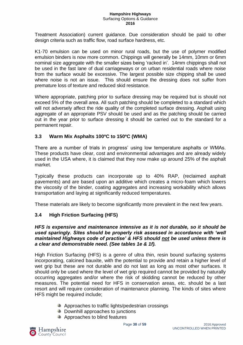
Hampshire Highways
Surfacing Options & Guidance 2016
Page 38 of 59 2016:Approved
UNCONTROLLED WHEN PRINTED
Treatment Association) current guidance. Due consideration should be paid to other design criteria such as traffic flow, road surface hardness, etc. K1-70 emulsion can be used on minor rural roads, but the use of polymer modified emulsion binders is now more common. Chippings will generally be 14mm, 10mm or 6mm nominal size aggregate with the smaller sizes being ‘racked in’. 14mm chippings shall not be used in the fast lane of dual carriageways or on urban residential roads where noise from the surface would be excessive. The largest possible size chipping shall be used where noise is not an issue. This should ensure the dressing does not suffer from premature loss of texture and reduced skid resistance. Where appropriate, patching prior to surface dressing may be required but is should not exceed 5% of the overall area. All such patching should be completed to a standard which will not adversely affect the ride quality of the completed surface dressing. Asphalt using aggregate of an appropriate PSV should be used and as the patching should be carried out in the year prior to surface dressing it should be carried out to the standard for a permanent repair. 3.3 Warm Mix Asphalts 100ºC to 150ºC (WMA) There are a number of trials in progress’ using low temperature asphalts or WMAs. These products have clear, cost and environmental advantages and are already widely used in the USA where, it is claimed that they now make up around 25% of the asphalt market. Typically these products can incorporate up to 40% RAP, (reclaimed asphalt pavements) and are based upon an additive which creates a micro-foam which lowers the viscosity of the binder, coating aggregates and increasing workability which allows transportation and laying at significantly reduced temperatures. These materials are likely to become significantly more prevalent in the next few years.
3.4 High Friction Surfacing (HFS)
HFS is expensive and maintenance intensive as it is not durable, so it should be used sparingly. Sites should be properly risk assessed in accordance with ‘well maintained Highways code of practise’ & HFS should not be used unless there is a clear and demonstrable need. (See tables 1e & 1f). High Friction Surfacing (HFS) is a genre of ultra thin, resin bound surfacing systems incorporating, calcined bauxite, with the potential to provide and retain a higher level of wet grip but these are not durable and do not last as long as most other surfaces. It should only be used where the level of wet grip required cannot be provided by naturally occurring aggregates and/or where the risk of skidding cannot be reduced by other measures. The potential need for HFS in conservation areas, etc. should be a last resort and will require consideration of maintenance planning. The kinds of sites where HFS might be required include;
Approaches to traffic lights/pedestrian crossings Downhill approaches to junctions Approaches to blind features

Hampshire Highways
Surfacing Options & Guidance 2016
Page 39 of 59 2016:Approved
UNCONTROLLED WHEN PRINTED
Tight Bends & especially combinations of the above
On kerbed carriageways there should be a 100mm gap between the HFS and the kerb face except where there are road markings adjacent to any kerbs in which case the HFS should be installed to the outside edge of those markings”
HFS can be applied either as a surface dressing system with the aggregate broadcast over a two part liquid thermosetting resin Cold Applied; or as a hot screed system where the aggregate is wholly embedded within a thermoplastic resin Hot Applied. There are seasonal constraints on the laying of the cold applied products that need to be carefully checked against relevant certification. The cold applied systems have proven to be the more durable and should be used in preference to the cheaper but less durable hot applied systems. The hot applied systems can be applied through out the year but are only suitable for areas that are not heavily trafficked. Both of the above systems should not be applied to new asphalt before the volatile elements within the bitumen have had an opportunity to evaporate and/or wear. Confirmation from the supplier will be needed to confirm the appropriate delay. For general guidance refer to RSTA Guide, The Code of Practice for High Friction Surfacing. MMA (Methyl Methacrylate) systems are cold applied. It has been claimed that these can be applied more quickly after surfacing has been completed. Written confirmation must be obtained that the installer’s guarantees are applicable in these instances. MMA is a more expensive option. Extents of High Friction Surfacing Bends - Where HFS is required, it should be provided over the full length of the bend to avoid significant variances in grip whilst cornering. On dual carriageways the need for HFS should be considered individually. On single carriageway sites HFS should be provided in both directions to avoid differential grip. Braking Areas - In braking areas, the length must consider the speed of approaching traffic and anticipated queuing lengths. The minimum length of HFS required under any given circumstances should be equivalent to a three second gap at the posted speed limit. The minimum lengths required are typically as follows;
30MPH – 50m (minimum) 40MPH – 60m 50MPH – 70m 60MPH – 90m 70MPH – 100m
Continuity - Where braking areas and/or bends run into one another a consistent level of grip should be maintained. This may lead to excessive lengths being proposed for HFS. In such instances alternatives should be considered to avoid the maintenance liability. In braking areas, HFS should be applied to all lanes approaching the hazard.
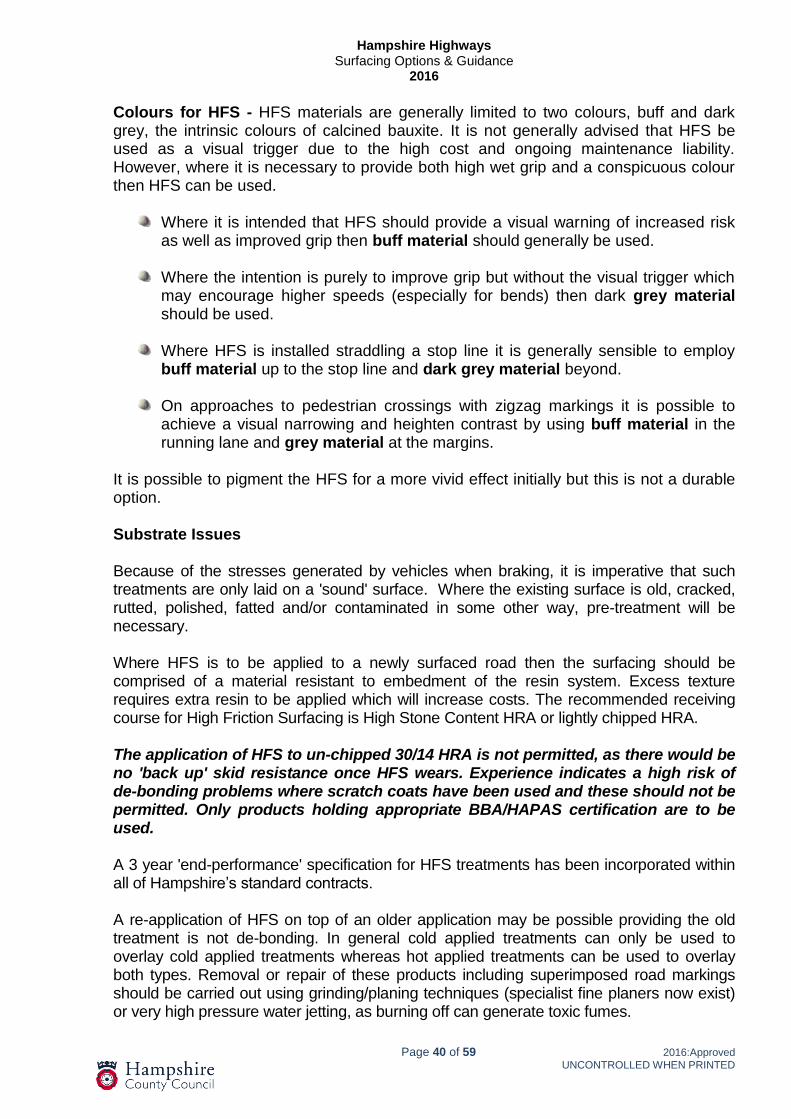
Hampshire Highways
Surfacing Options & Guidance 2016
Page 40 of 59 2016:Approved
UNCONTROLLED WHEN PRINTED
Colours for HFS - HFS materials are generally limited to two colours, buff and dark grey, the intrinsic colours of calcined bauxite. It is not generally advised that HFS be used as a visual trigger due to the high cost and ongoing maintenance liability. However, where it is necessary to provide both high wet grip and a conspicuous colour then HFS can be used.
Where it is intended that HFS should provide a visual warning of increased risk as well as improved grip then buff material should generally be used.
Where the intention is purely to improve grip but without the visual trigger which
may encourage higher speeds (especially for bends) then dark grey material should be used.
Where HFS is installed straddling a stop line it is generally sensible to employ
buff material up to the stop line and dark grey material beyond.
On approaches to pedestrian crossings with zigzag markings it is possible to achieve a visual narrowing and heighten contrast by using buff material in the running lane and grey material at the margins.
It is possible to pigment the HFS for a more vivid effect initially but this is not a durable option. Substrate Issues Because of the stresses generated by vehicles when braking, it is imperative that such treatments are only laid on a 'sound' surface. Where the existing surface is old, cracked, rutted, polished, fatted and/or contaminated in some other way, pre-treatment will be necessary. Where HFS is to be applied to a newly surfaced road then the surfacing should be comprised of a material resistant to embedment of the resin system. Excess texture requires extra resin to be applied which will increase costs. The recommended receiving course for High Friction Surfacing is High Stone Content HRA or lightly chipped HRA. The application of HFS to un-chipped 30/14 HRA is not permitted, as there would be no 'back up' skid resistance once HFS wears. Experience indicates a high risk of de-bonding problems where scratch coats have been used and these should not be permitted. Only products holding appropriate BBA/HAPAS certification are to be used. A 3 year 'end-performance' specification for HFS treatments has been incorporated within all of Hampshire’s standard contracts. A re-application of HFS on top of an older application may be possible providing the old treatment is not de-bonding. In general cold applied treatments can only be used to overlay cold applied treatments whereas hot applied treatments can be used to overlay both types. Removal or repair of these products including superimposed road markings should be carried out using grinding/planing techniques (specialist fine planers now exist) or very high pressure water jetting, as burning off can generate toxic fumes.

Hampshire Highways
Surfacing Options & Guidance 2016
Page 41 of 59 2016:Approved
UNCONTROLLED WHEN PRINTED
All road markings on high friction surfacing shall be at least level with the surrounding high friction surface after treatment. It is accepted that markings may need to be applied in advance and it is sometimes expedient to 'mask' road markings prior to re-treatment. This practice can leave the markings lower than the HFS which can hold surface water Under such circumstances, it will be necessary to reapply markings on completion of HFS works. 3.5 Grouted Macadam
Grouted macadam surfacing has been developed for use in very highly stressed areas to withstand ‘exceptional’ forces. They consist of an open-graded bituminous 'receiving course' (usually an SMA) into which is vibrated a cementitous grout to provide an extremely strong material that is highly resistant to deformation, fuel spillages and fretting. These materials offer solutions to highly stressed sites such as bus stops, HGV laybys or turning areas. To be effective the treatment must be applied to a sound substrate and be allowed to ‘cure’ fully before trafficking. It is important to ensure the grout penetrates well into the voids. It is not a suitable process for sites that need to offer skid resistance unless shot blasting or similar process is used to expose coarse aggregate. The material must have BBA/HAPAS certification
3.6 Concrete pavements
Concrete carriageways present significantly different maintenance issues than bituminous ones. The principle difference being that the opportunities to plane and relay a surface course does not exist. For bus stops or similar laybys concrete construction is often the best option as it provides a rigid, durable rut resistant surface. Within Hampshire there are many composite/rigid pavements due to clay or other poor formation. Some of these have been overlaid with varying thicknesses of asphalt. When considering maintenance options the following matters should be taken into account;
Joints - Where the edges of concrete slabs are sound, joint sealing treatment should be considered. Where the concrete edge (arris) has deteriorated consideration should be given to the use of a ‘rout and seal’ joint treatment. The depth and width needing to be routed out will vary However unless all deteriorated material is removed, any treatment will not be effective. Exposed Slabs - Where the concrete surface is exposed there are various specialist repair materials that can be used for ‘thin bonded’ and ‘arris repairs’. Retexturing can also reinvigorate the existing slabs. Detailed guidance on repairs to concrete carriageways is contained in the Highways Agency/Brit-pave manual entitled ‘Concrete Pavement Maintenance Manual’ (ISBN 0-946691-89-4) and HD 32/94 of Volume 7 of the Design Manual for Roads and Bridges.

Hampshire Highways
Surfacing Options & Guidance 2016
Page 42 of 59 2016:Approved
UNCONTROLLED WHEN PRINTED
Overlaying - Where an asphalt overlay is appropriate, consideration must be given to possible movements at joints. It is important to ascertain whether any movement occurring is thermal in nature or whether the concrete slabs are 'rocking'. With 'rocking slabs' it may be possible to see the slabs move under the weight of traffic. Overlaying should not take place when such movement is apparent.
For rocking or moving slabs it may be possible to rectify the issue with specialist grouting techniques. The consequences of thermal movement (reflective cracking) may be overcome in one of the following ways:
By applying a very thick overlay, usually 150mm minimum to negate thermal stresses. This is expensive and often not a practical solution. A nominal reduction in the thickness of overlay required can be achieved in one of two ways as follows:
By reinforcing the overlay. Various grids have been used successfully at a
number of sites in Hampshire, glass fibre and steel (see section 3.8).
By employing a Stress Absorbing Membrane (SAM), at the interface. SAMs ensure that localised stresses are dissipated within the overlay such that reflected cracking does not occur. A number of proprietary SAMs are available, some preformed, and others applied hot. Experience suggests that localised treatments are not particularly effective.
Recent thinner overlays have been successful using proprietary 942 surface courses incorporating Polymer Modified Binders (PMBs) & low void content. These have been laid at a nominal thickness of 50mm and have proven more able to tolerate underlying movement than stiffer hot rolled asphalts as the PMB gives increased flexibility and resistance to fatigue and reflective cracking. Where slabs are badly deteriorated and where an overlay would otherwise be suitable, it may be possible to convert the existing pavement into a flexible sub-base/base layer using a “crack and seat” technique. However, cracking and seating is only likely to be appropriate for major routes and is not an option for most ‘local roads’.

Hampshire Highways
Surfacing Options & Guidance 2016
Page 43 of 59 2016:Approved
UNCONTROLLED WHEN PRINTED
3.7 Retexturing
Where the only defect with an existing road surface is a localised loss of surface texture it may be possible to reintroduce texture. For this process to be appropriate the existing surfacing must be structurally sound. HCC Clause 773AR refers. Table 3a: Guidance on Retexturing
Surfacing type
Original condition
Effect required
from treatment
Suitability of Process
Bush
hammering
Shot
blasting
High pressure
water jetting
Chipped HRA
Polished Aggregate
Restore Micro
texture
Likely to be
effective
*Likely to
be most effective
Not Suitable
Chipped HRA
Embedded Chippings
Restore Macro texture
Not Suitable
Likely to be
effective
*Likely to be
most effective
Chipped HRA
Embedded Chippings and
Polished Aggregate
Restore Micro & Macro texture
Not Suitable
*Likely to
be most effective
Not Suitable
Close Graded
Macadam HSCA/NTSC
Polished Aggregate
Restore Micro
texture
Likely to be effective
*Likely to
be most effective
Not Suitable
Close Graded
Macadam HSCA /NTSC
Inadequate surface texture
due to abrasion
Restore Macro texture
Not Suitable
*Likely to
be effective
Likely to be effective
Close Graded
Macadam HSCA/NTSC
Excess binder on or in surface
Restore Micro & Macro texture
Not Suitable
Not Suitable
*Likely to be
most effective
Surface Dressing
Excessive Embedment /
Fatting
Restore Macro texture
Not Suitable
Not Suitable
*Likely to be
most effective
Concrete Polished aggregate
Restore Micro
texture
Likely to be effective
*Likely to
be most effective
Not Suitable
Concrete Loss of Surface Texture
Restore Macro texture
*Grooving
necessary for high speed
sites
Only suitable on low speed
sites
Not Suitable
HSCA = High Stone Content Asphalt NTSC = Negative Textured Surface Course
* Denotes preferred option
Care should be taken as retexturing can have a considerable effect on reducing the serviceable life of the surface course. Various methods are available but they need to be applied selectively and should not be considered as a long term fix.

Hampshire Highways
Surfacing Options & Guidance 2016
Page 44 of 59 2016:Approved
UNCONTROLLED WHEN PRINTED
3.8 Asphalt Reinforcement Grids
The inclusion of an ARG assists in the dissipation of the tensile strain exerted by traffic loading, which increases resistance to cracking. The best increase in this resistance to tensile strain is achieved when a grid is incorporated deep within the bound layers.
Grids cannot be expected to cover significant underlying faults in the structure of the pavement.
A common application is as a means of bridging existing utility reinstatements thereby delaying the onset of reflective cracking. There are claims and anecdotal evidence that this use of grids is successful above trenches, joints or cracks. Caution should be exercised when specifying grid beneath surface course only as there is an inherent problem with the grid failing to adhere to the underlying surface especially if planed. The forces exerted by the floating screed of a paving machine can often drag the grid to the point where the adhesion fails and the grid drags or becomes rumpled.
There are many forms of reinforcing grid but the most common three categories are:
Glass Fibre Mesh, self adhesive or stuck with hot applied bitumen spray.
Steel mesh physically fixed to under lying layers. Whilst this has proven performance credentials it is difficult to remove as it cannot be planed.
Glass fibre mesh/fabric composites absorb bitumen to form an additional barrier to water.
Glass fibre mesh/fabric composite is the preferred option as these are ‘glued’ to the surface by the application of the bond coat which also provides an impermeable barrier.
The following are common problems where specification of a grid may be worthwhile:
Thermal Cracking 'Fine' cracks with no vertical displacement (e.g. reflective cracking over lean concrete). Glass Fibre Grid with/without geotextile backing depending on site circumstances. The grid shall comply with the following requirements:
Glass-fibre mesh or a composite glass-fibre mesh on geotextile backing.
Minimum tensile strength of 100kn/m in both longitudinal and transverse directions.
The minimum overlay thickness for the grid should be 70mm
The grid shall be fixed to the carriageway using a bond coat approved by the grid supplier/manufacturer or may be self adhesive.

Hampshire Highways
Surfacing Options & Guidance 2016
Page 45 of 59 2016:Approved
UNCONTROLLED WHEN PRINTED
As an alternative consider a dense, 943 Asphalt with PMB, or proprietary SAMI (stress absorbing interlayer membrane) asphalt which can also offer crack suppression.
Cracking with Anticipated Vertical Displacement
Glass Fibre Composite Grid
The grid shall comply with the following requirements:
Composite glass-fibre mesh on geotextile backing -minimum tensile strength of 100kN/m in both longitudinal and transverse directions.
Manufacturers specify a minimum of 40 or 50mm overlay, however this can cause issue with de-bonding during the overlay operation however thicker overlays are preferable. There is also little value when the grid is incorporated into the pavement at such a high level. The grid shall be fixed to the carriageway using an emulsified bond coat or hot bitumen in accordance with the supplier/ manufacturer product certification.
This type of grid does provide a waterproof membrane within the pavement reducing ingress of water.
Clay Shrinkage Cracking
For wider cracks Polypropylene grid with/without geotextile backing may be appropriate. These grids can be difficult to install as some need to be tensioned. The minimum overlay thickness is 70 mm.
The grid shall be fixed to the carriageway using an emulsified bond coat or hot bitumen in accordance with the supplier/ manufacturer product certification. Grids cannot be expected to cover major underlying failures or the significant swell or shrinkage often associated with clay foundations.
Concrete Joint problems/severe Clay Shrinkage cracking
Metal mesh can be specified where more severe movement has to be contended with. These are to be installed and fixed to manufactures specification However there is a potential maintenance liability when the need to plane into these layers.
In all cases grids must be laid by contractors experienced with the laying of that type of product and in accordance with the manufacturer's instructions.

Hampshire Highways
Surfacing Options & Guidance 2016
Page 46 of 59 2016:Approved
UNCONTROLLED WHEN PRINTED
3.9 Crack Sealing Techniques
Where there is surface cracking in an otherwise sound condition then consideration should be given to sealing the cracks to prevent the ingress of water.
Excess sealant can be slippery and is hazardous to two wheeled vehicles so sealant on the surface should be kept to a minimum with a maximum band width of 40mm and a maximum thickness of 3mm. 3mm grit with a minimum PSV of 55 should be applied to all bituminous over-band sealing. The requirement for grit may be waived for non-bituminous (e.g. resin based) sealants where an equivalent skid resistance can be demonstrated. For joint sealing beneath surface course there is no requirement for a skid resistance although certain systems may require a coating of grit to prevent bleeding or tracking of the applied joint during construction. Approved Non-Bituminous Sealant shall be applied strictly in accordance with the manufacturer’s method statement and HAPAS/BBA certification. 3.10 Asphalt Rejuvenation/Preservation Asphalts degrade over time by the combined effects of temperature, oxidation, moisture, ultra-violet light and wear which strip the volatile fractions from the bitumen, reducing flexibility. The service life of surface courses can be extended by the application of rejuvenation sprays. These sprays replace the volatile fractions without denuding or masking surfacing texture. Asphalt rejuvenator/preservatives will only help to bind the surface aggregates together in order to reduce fretting and /or other aggregate loss. It does not fully penetrate low void content asphalt. Treatment prior to significant deterioration, topped up at five yearly intervals is likely to provide the greatest whole life cost benefit. This process is particularly appropriate for the treatment of SMA or clause 942 materials. 3.11 In-situ Recycling Techniques Hampshire County Council has a policy of encouraging environmental initiatives and is keen to promote recycling where appropriate. Given the commercial and environmental advantages for recycling of the aggregates contained within existing roads a number of effective proprietary ‘in-situ’ treatments have evolved. Some proprietary processes are appropriate on lower category roads. Cement and/or other hydraulic binders may be used as a binder for recycling works. On lightly trafficked roads it may suffice to apply only surface course over the recycled material. On more heavily trafficked roads the recycled material is best used as a base layer.

Hampshire Highways
Surfacing Options & Guidance 2016
Page 47 of 59 2016:Approved
UNCONTROLLED WHEN PRINTED
Sites with extensive ironwork in the road, shallow services, variable construction and/or clay sub grades are not suitable and/or economic to recycle. Where such options are considered, an investigation may be necessary to assess the existing surfacing material/s for suitability (HD31/94). Most in-situ recycling processes are only likely to be viable for large schemes. 3.12 Ex-Situ Recycling (Cold Recycled Materials)
Hampshire has developed a facility to recycle tar bound planings and other arisings from the network to produce a variety of hydraulically bound materials designed and produced in accordance with TRRL Report 611 and HCC HBM Specification (Clause 894AR). The recycled material produced remotely should be better in quality than in situ options due to increased quality control at the production unit. It can be laid and compacted using conventional paving equipment. This process has been used extensively for base or sub-base substitution in all classes of road. It has also been used to replace sub-base and binder course material in footways, Hydraulically Bound Material (HBM) is a recycled construction material made from aris-ings from the highway network. This is a cold produced material, which has environ-mental, economic and operational benefits. It can be used as sub base, base and bind-er course material. The compressive strength should be limited to 5 to 6 N/mm² to avoid cracking. As a cold produced material it is less energy intensive to produce, safer to lay and can be stored for longer periods of time. HBM sets and hardens by hydraulic action and has water content suitable for compac-tion by rolling. HBM can be produced as quick set (with cement) or slow set (with other materials such as fly ash), depending on the client requirement. It is sensitive to mois-ture, more so than traditional materials. As such it must be stored under cover and pro-tected from wind and rain to minimise loss or gain of moisture. It also needs to be pro-tected from extreme changes in temperature to prevent deterioration.
The setting and hardening of slow set HBM is protracted when the ambient temperature is 5 degrees or less so careful consideration must be given to the use of HBM during late autumn or winter.
Quick set HBM can suffer from the formation of thermal stress cracks, due to shrinkage during the curing period. HBM can be pre-cracked in order to control the location and size of surface cracks as with rigid pavement construction. The permeability and strengths of HBM change with time therefore curing time is crucial to durability testing. Factors such as aggregate gradation, requirements for immediate trafficking and laying temperature, are critical to attaining acceptable durability.
Local ground conditions should be considered when specifying HBM as it can be susceptible to aggressive ground and organic impurities which may interfere with the hydraulic reaction. Due to the sensitivity of HBM to moisture, HBM should not be laid in heavy rain, or on wet/saturated ground.

Hampshire Highways
Surfacing Options & Guidance 2016
Page 48 of 59 2016:Approved
UNCONTROLLED WHEN PRINTED
4 Appendix 7/1: Permitted Pavement Materials 4.1 Requirements for Regulating Course
Regulating thicknesses of less than 10mm/15mm (dependent upon the materials permitted within each surfacing appendix) shall be achieved within the thickness of the overlying bituminous material, unless otherwise agreed.
*For possible use in cold winter weather conditions
Ref No Layer
Thickness (mm)
Regulating Material Grade of Binder
Special Requirements
1 0 – 20 HRA 0/2 F surf 40/60 des
to –BS EN 13108-4 40/60 pen
only
Wheel-tracking/stability criteria to match that specified for Surface Course.
2a 15 to 25 SMA 6 reg 40/60
Stone Mastic Asphalt to Clause 937
40/60 pen Wheel-tracking criteria to match that specified for Surface Course.
2b 25 to 35 SMA 10 reg 40/60
2c 35 to 45 SMA 14 reg 40/60
2d 50 to 65 SMA 20 reg 40/60
3 35 - 65 HRA 50/14 bin des 40/60
to –BS EN 13108-4 40/60 pen
Wheel-tracking/stability criteria to match that specified for Surface Course
4a
50-100
AC 20 dense bin 40/60 des to –BS EN 13108-1 & Clause 929
40/60 Pen
Coarse Aggregate to be crushed
rock or slag. Fine aggregate to
exclude natural sand fines
Wheel-tracking criteria to match that specified for Surface Course. Where no requirement is stated these may be recipe mixes
4b AC 20 dense bin 100/150 des
to –BS EN 13108-1 & Clause 929 100/150 Pen*
4c AC 20 HDM bin 40/60 des
to –BS EN 13108-11 & Clause 929 40/60 Pen
5a
70-120
AC 32 dense bin 40/60 des to –BS EN 13108-1 & Clause 929
40/60 Pen
Coarse Aggregate to be crushed
rock or slag.
Fine aggregate to exclude natural sand fines
Wheel-tracking criteria to match that specified for Surfacing Course
Where no requirement is stated these may be recipe mixes.
5b AC 32 dense bin 100/150 des
to –BS EN 13108-1 & Clause 929 100/150 Pen*
5c AC 32 HDM bin 40/60 des to –BS EN 13108-1 & Clause 929
40/60 Pen
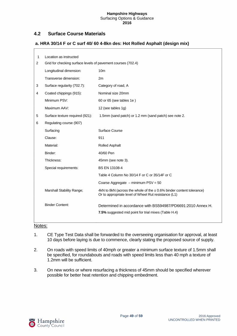
Hampshire Highways
Surfacing Options & Guidance 2016
Page 49 of 59 2016:Approved
UNCONTROLLED WHEN PRINTED
4.2 Surface Course Materials
a. HRA 30/14 F or C surf 40/ 60 4-8kn des: Hot Rolled Asphalt (design mix)
1
Location as instructed
2 Grid for checking surface levels of pavement courses (702.4)
Longitudinal dimension: 10m
Transverse dimension: 2m
3 Surface regularity (702.7): Category of road, A
4 Coated chippings (915): Nominal size 20mm
Minimum PSV: 60 or 65 (see tables 1e )
Maximum AAV: 12 (see tables 1g)
5 Surface texture required (921): 1.5mm (sand patch) or 1.2 mm (sand patch) see note 2.
6 Regulating course (907)
Surfacing Surface Course
Clause: 911
Material: Rolled Asphalt
Binder: 40/60 Pen
Thickness: 45mm (see note 3).
Special requirements: BS EN 13108-4
Table 4 Column No 30/14 F or C or 35/14F or C
Coarse Aggregate – minimum PSV = 50
Marshall Stability Range; 4kN to 8kN (across the whole of the ± 0.6% binder content tolerance) Or to appropriate level of Wheel Rut resistance (L1)
Binder Content:
Determined in accordance with BS594987/PD6691:2010 Annex H.
7.5% suggested mid point for trial mixes (Table H.4)
Notes:
1. CE Type Test Data shall be forwarded to the overseeing organisation for approval, at least 10 days before laying is due to commence, clearly stating the proposed source of supply.
2. On roads with speed limits of 40mph or greater a minimum surface texture of 1.5mm shall be specified, for roundabouts and roads with speed limits less than 40 mph a texture of 1.2mm will be sufficient.
3. On new works or where resurfacing a thickness of 45mm should be specified wherever possible for better heat retention and chipping embedment.

Hampshire Highways
Surfacing Options & Guidance 2016
Page 50 of 59 2016:Approved
UNCONTROLLED WHEN PRINTED
b. HRA 35/14 F or C surf 40/60 des L2 WT: Hot Rolled Asphalt (design mix performance related) 1 Location as instructed
2 Grid for checking surface levels of pavement courses (702.4)
Longitudinal dimension: 10m
Transverse dimension: 2m
3 Surface regularity (702.7): Category of road, A
4 Pre-coated Chippings: Nominal size 20mm
Minimum PSV: 65 or 68 (see table 1e )
Maximum AAV: 12 (See table 1g)
5 Surface texture required (921): Sand patch texture requirements
Level Minimum sand patch texture depth new (mm)
Minimum sand patch texture depth at 2 yrs. (mm)
Loss of texture between 12 months and 2 years (%)
2 1.5 1.5 40 max
1 1.2 1.2 40 max
No individual 50m section shall be less than 80% of that specified for the relevant ‘level’, nor more than 2.2 mm.
6 Regulating course (907)
7 Coring and testing for the determination of wheel tracking shall be carried out in accordance with Clause 943 & BS 594987
8 Wheel-tracking test temperature, rate and rut depth (to BS EN 12697)
Wheel-tracking levels (See Notes 3 and 4)
Level
Test temperature
Wheel tracking requirements
Rate (mm/hr) Mean / [max}
Rut depth (mm) Mean / [max]
2 60 5.0/[7.5] 7.0/[10.5]
‘Mean’ is the mean result of 6 consecutive results and ‘max’ is the maximum value measured on a single core.
Surfacing: Hot Rolled Asphalt (performance Design Mixture)
Clause: 943 and BS EN13108-4: Table No 4
Column No 35/14F or C
Special Requirements: If modified Binders are to be used, only Pre-blended modified binders are acceptable
Material: HRA 35/14 F or C surf 40/60 des PSV (see note 2)
Binder: 40/60
Thickness: 45mm
Coarse Aggregate: Minimum PSV = 50
Binder Content: Determined in accordance with BS594987/PD6691:2010 Annex H.
7.0% suggested mid point for trial mixes (Table H.4)
Air voids: Not greater than 7.5% for any pair of cores and not greater than 5.5% for the mean of any six consecutive cores.
Notes:
1. CE Type Test Data shall be forwarded for approval, at least 15 days before laying, stating the proposed source of supply. A Mixture Approval trial may be required where relevant wheel-tracking/air voids data is not available.
2.
The surface texture should be assessed on a site specific basis and a maximum in accordance with IAN 154/12.
3 The wheel tracking level needed should be assessed on a site specific basis taking account of the nature of the site and commercial vehicle flows. Refer to the Section 1 of this document.
4. Wheel-tracking testing shall be carried out at 60°C. All results shall be no more than 12 months old.

Hampshire Highways
Surfacing Options & Guidance 2016
Page 51 of 59 2016:Approved
UNCONTROLLED WHEN PRINTED
Where such data is not available, a Job Mixture Approval Trial shall be required for each unique mixture.
c. AC 14 close surf 100/150 (or 40/60): Asphaltic Concrete 14
1
Location as instructed
2 Grid for checking surface levels of pavement courses (702.4)
Longitudinal dimension: 10m
Transverse dimension: 2m
3 Surface regularity (702.7): Category of road, A
4 Surface texture required (921) N/A
5 Regulating course (907)
Surfacing Surface Course
Clause: 912
Material: AC 14 close surf 100/150 PSV (see note 2)
Binder: 100/150 or 40/60 See Note 1
Thickness: 40mm
Special requirements: BS EN 13108-1
Coarse Aggregate: Crushed rock or slag only excluding limestone
Adhesion agent required if quartzite, basalt or other igneous rock.
Minimum PSV: 55 or 60 (see Note 2)
Maximum AAV: 16 (see Note 2)
Fine Aggregate: Crushed rock and natural sand mixture
Notes:
1. 2.
160/220 pen binder may be considered for use during the winter months only but care must be exercised as such materials is likely to deform during later periods of warm weather. 40/60 pen binder is only practical for machine laying. For selection of coarse aggregate properties refer to tables 1e, & 1g.

Hampshire Highways
Surfacing Options & Guidance 2016
Page 52 of 59 2016:Approved
UNCONTROLLED WHEN PRINTED
d. AC 10 close surf 100/150 (or 40/60): Asphalt Concrete 10
1
Location as instructed
2 Grid for checking surface levels of pavement courses (702.4)
Longitudinal dimension: 10m
Transverse dimension: 2m
3 Surface regularity (702.7): Category of road, A
4 Surface texture required (921) N/A
5 Regulating course (907)
Surfacing Surface Course
Clause: 912
Material: AC 10 close surf 100/150 PSV (see note 2)
Binder: 100/150 or 40/60 Pen – See Note 1
Thickness: 40mm (absolute minimum of 30mm)
Special requirements: BS EN 13108-1
Coarse Aggregate: Crushed rock or slag only
Adhesion agent required if quartzite, basalt or other igneous rock.
Minimum PSV: 55 or 60 (see Note 2)
Maximum AAV: 16 (see Note 2)
Fine Aggregate: Crushed rock and natural sand mixture
Notes:
1. 2.
160/220 pen binder may be considered for use during the winter months but care must be exercised as such materials may deform during later periods of warm weather. 40/60 pen binder is only practical for machine laying. For selection of coarse aggregate properties refer to tables 1e, & 1g

Hampshire Highways
Surfacing Options & Guidance 2016
Page 53 of 59 2016:Approved
UNCONTROLLED WHEN PRINTED
e. HRA 55/14 F or C surf 40/60 des 7kn: High Stone content Hot Rolled Asphalt (design mix)
1
Location as instructed
2 Grid for checking surface levels of pavement courses (702.4)
Longitudinal dimension: 10m
Transverse dimension: 2m
3 Surface regularity (702.7): Category of road, A
4 Surface texture required (921) N/A
5 Regulating course (907)
Surfacing Surface Course
Clause: 911
Material: High Stone Content Asphalt
Binder: 40/60
Thickness: 45mm
Special requirements: BS EN 13108-4 Table No 4 Column No 55/14F or C
Marshall Stability Range:
Binder Content:
7kN minimum (across the whole of the ±0.6% binder content tolerance)
Or to appropriate level of Wheel Rut resistance (L1)
Determined in accordance with BS594987/PD6691:2010 Annex H.
5.5% suggested mid point for trial mixes (Table H.4)
Maximum Flow 5.0mm
Wheel Tracking Requirement Level 1
Coarse Aggregate: Crushed rock or slag excluding Limestone
Nominal size: 0/14mm
Minimum PSV: 60 or 65 (see Note 2)
Maximum AAV: 12 (see Note 2)
Notes:
1. 2.
CE Type Test Data shall be forwarded to the Overseeing Organisation for approval, at least 10 days before laying is due to commence, clearly stating the proposed source of supply. For selection of coarse aggregate properties refer to tables 1e, & 1g.

Hampshire Highways
Surfacing Options & Guidance 2016
Page 54 of 59 2016:Approved
UNCONTROLLED WHEN PRINTED
f. Clause 942 Proprietary Surface Course14mm
1
Location as instructed
2 Grid for checking surface levels of pavement courses (702.4)
Longitudinal dimension: 10m
Transverse dimension: 2m
3 Surface regularity (702.7): Category of road, A
4 Coarse Aggregate: Nominal size: 0/14mm
Minimum PSV 68, 65 or 60 – See table 1f.
Maximum AAV: See table 1g.
5 Surface texture required (921): As per IAN 154/12 – see tables 1c & 1d
6 Regulating course (907):
7 Wheel-tracking test temperature: 60°C
8 Wheel-tracking test temperature, rate and rut depth (to BS EN 12697)
Wheel-tracking levels (see Note 5)
Level Test Temperature
C
Wheel tracking requirements
Rate (mm/hr) Mean/[max]
Rut depth (mm) Mean / [max]
3 60 5.0/[7.5] 7.0 / [10.5]
‘Mean’ is the mean result of 6 consecutive results and ‘max’ is the maximum value measured on a single core.
Surfacing: Surface Course
Clause: 942
Material: Proprietary Surface Course 14 mm
Binder:
Thickness: 50mm (subject to BBA certification)
Special Requirements:
Minimum target binder content: Bact 6.0%
Binder volume: Not less than 12%
Binder drainage composition: Not more than 0.3% by mass at target binder
Laboratory air voids content: 2.0% to 4.0% within the range ± 0.6% of target binder
Noise Level: 0, 1, 2, or 3 as instructed (see Note 6)
Surface texture See note 2.
Notes: 1. CE Type Test Data shall e forwarded to the Overseeing Organisation for approval, at least 10 days
before laying is due to commence, clearly stating the proposed source of supply. This should be taken into account when programming works.
2.
Texture depths shall be in accordance with IAN 154/12 for minimum and maximum textures.
3. 4.
Where required, by the Overseeing Organisation, proprietary thin surface courses shall be gritted in accordance with clause 973AR. For selection of coarse aggregate properties refer to tables, pages 1f & 1g.
5. 6.
Results from wheel-tracking tests to BS 598 Part 110 shall be provided at the approval stage to the Overseeing Organisation. Testing shall be carried out at 60°C with results being no more than 12 months old. If traffic noise is an issuer refer to Section 1.7 page 20

Hampshire Highways
Surfacing Options & Guidance 2016
Page 55 of 59 2016:Approved
UNCONTROLLED WHEN PRINTED
g. Clause 942 Proprietary Surface Course 10mm
1
Location as instructed
2 Grid for checking surface levels of pavement courses (702.4)
Longitudinal dimension: 10m
Transverse dimension: 2m
3 Surface regularity (702.7): Category of road, A
4 Course Aggregate: Nominal size: 0/10mm
Minimum PSV 68, 65 or 60 – See tables 1f & 1g
Maximum AAV: See table 1g.
5 Surface texture required (921): As per IAN154/12 see tables 1c & 1d
6 Regulating course (907)
7 Wheel-tracking test temperature: 60°C
8 Wheel-tracking test temperature, rate and rut depth (to BS EN 12697)
Wheel-tracking levels (see Note 3)
Level Test Temperature
C
Wheel tracking requirements
Rate (mm/hr) Mean/[max]
Rut depth (mm) Mean / [max]
3 60 5.0/[7.5] 7.0 / [10.5]
‘Mean’ is the mean result of 6 consecutive results and ‘max’ is the maximum value measured on a single core.
Surfacing: Surface Course
Clause: 942
Material: Proprietary Surface Course 10mm
Thickness: 30 to 40mm (subject to BBA certification)
Special Requirements:
Minimum target binder content: Bact 6.2%
Binder volume: Not less than 12%
Binder drainage composition: Not more than 0.3% by mass at target binder composition
Noise Level: 0, 1, 2, or 3 as instructed. (See Note 4)
Laboratory Air voids 2.0% to 4.0% within the range ± 0.6% of target binder content.
Notes: 1. CE Type Test Data shall be forwarded to the Overseeing Organisation for approval, at least
10 days before laying is due to commence, clearly stating the proposed source of supply. This should be taken into account when programming works.
2.
Texture depths shall be in accordance with IAN 154/12 for minimum and maximum textures.
3. 4. 5. 6.
Where required, by the Overseeing Organisation, proprietary thin surface courses shall be gritted in accordance with clause 973AR. For selection of coarse aggregate properties refer to tables pages 1f & 1g. Results from wheel-tracking tests to BS 598 Part 110 shall be provided. Testing shall be carried out at 60°C with results being no more than 12 months old. If traffic noise is an issuer refer to Section 1.7 page 20

Hampshire Highways
Surfacing Options & Guidance 2016
Page 56 of 59 2016:Approved
UNCONTROLLED WHEN PRINTED
h. Clause 942 Proprietary Surface Course 6mm
1
Location as instructed
2 Grid for checking surface levels of pavement courses (702.4)
Longitudinal dimension: 10m
Transverse dimension: 2m
3 Surface regularity (702.7): Category of road, A
4 Course Aggregate: Nominal size: 0/6mm
Minimum PSV 55, or 60 (see note 4)
Maximum AAV: 16
5 Regulating course (907) Table 1 mixture options: 2a to 2d, 4a, 4c, 5a or 5c
Surfacing: Surface Course
Clause: 942
Material: 6mm Proprietary Thin Surface Course
Binder:
Thickness: 30mm
Special Requirements:
Minimum Target Binder Content Bact 6.8%
Binder volume Not less than 12%
Binder drainage composition Not more than 0.3% by mass at target binder
Laboratory air voids content 2.0% to 4.0% within the range ± 0.6% of target binder
Notes:
1. CE Type Test Data shall e forwarded to the Overseeing Organisation for approval, at least 10 days before laying is due to commence, clearly stating the proposed source of supply. This should be taken into account when programming works.
2.
Texture depths shall be in accordance with IAN 154/12 for minimum and maximum textures.
3. 4.
Where required, by the Overseeing Organisation, proprietary thin surface courses shall be gritted in accordance with clause 973AR. For selection of coarse aggregate properties refer to tables, pages 1f & 1g.
5. Results from wheel-tracking tests to BS 598 Part 110 shall be provided at the approval stage to the Overseeing Organisation. Testing shall be carried out at 60°C with results being no more than 12 months old.
6. If traffic noise is an issue refer to Section 1.7 page 20

Hampshire Highways
Surfacing Options & Guidance 2016
Page 57 of 59 2016:Approved
UNCONTROLLED WHEN PRINTED
i. HRA 15/10 F or C surf 40/60 rec or des: Hot Rolled Asphalt (for hand laid reinstatements)
1
Location:
This material shall only be used in hand patching and for reinstatement in front of
kerbs, to transverse trenches and around ironwork
2 Coated chippings (915): Nominal size: 14/20mm
Minimum PSV: 60
Maximum AAV: 12
3 Surface texture required (921): 0.90 (SMTD) / 1.2 mm (sand-patch)
4 Regulating course (907): NA
Surfacing: Surface Course
Clause: 910/911 recipe or design mix
Material: Hot Rolled Asphalt
Binder: 40/60 Pen
Thickness: 45mm
Special Requirements: BS EN 13108-4
Table 4, Column No 15/10 F or C
Coarse Aggregate: Crushed rock or Slag – minimum PSV = 50
Binder Content: Determined in accordance with BS594987/PD6691:2010 Annex H.
8.5% suggested mid point for trial mixes

Hampshire Highways
Surfacing Options & Guidance 2016
Page 58 of 59 2016:Approved
UNCONTROLLED WHEN PRINTED
4.3 Binder Courses Schedule of Binder Course Mixtures
Element Clause Material Binder Grade
Layer Thickness
(mm)
Special Requirements
Binder Course
905 HRA 50/14 bin 40/60
40/60 pen
As instructed
BS EN 13108-4
Coarse Aggregate to be crushed rock or slag.
Binder Course
906 AC 20
dense bin 40/60 recipe
40/60 pen
As instructed (between
50mm and 100mm)
BS EN 13108-1
Coarse Aggregate to be crushed rock or slag.
Compaction to Clause 929
906
AC 20 dense bin 100/150
recipe*
100/150 pen
929 AC 20
Dense bin 40/60 design
40/60 pen
Binder Course
937 SMA 14 bin
40/60
40/60 pen
As instructed
(between 50mm and
65mm)
60˚C Wheel-tracking criteria applies:
Max. wheel-tracking rate to PD6691 Annex D
Binder
Course
894AR
Hydraulically Bound Materials
NA 100mm See HHSC Specification Clause 894AR
* For possible use in cold winter weather conditions

Hampshire Highways
Surfacing Options & Guidance 2016
Page 59 of 59 2016:Approved
UNCONTROLLED WHEN PRINTED
4.4 Base Mixtures Schedule of Base Mixtures
Element Clause Material Binder Grade
Layer Thickness (mm)
Special Requirements
Base
906 AC 32 dense
base 40/60 rec 40/60 pen
As instructed
(between 70mm and 120mm)
BS EN 13108-1
Coarse Aggregate to be crushed rock or slag.
Compaction to Clause 929
906
AC 32dense base 100/150
rec *
100/150 pen
929 AC 32 HDM
base 40/60 des 40/60 pen
894AR Hydraulically
Bound Materials N/A
See HHSC Specification Clause 894AR
1030 C8/10 Wet Lean
Concrete N/A
As instructed (minimum 150mm)
To be fully compacted by internal vibration only. Crack inducers to be max 3m centres.
Mixes must achieve equivalent of 7 days strength before overlaying permitted.
Maximum strength of 10N/mm² at 7 days
ST mixes not permitted.
930 AC 10 EME2 Base 10/12 or 15/25 pen
60 to 100mm Has to be laid on well compacted sub base surface stiffness 120mpa.
* For possible use in cold winter weather conditions
`