GRC and GFRP for new structures and seismic rehabilitationjcorreia/Papers/ICPaper8.pdfGRC - Glass...
11
1 INTRODUCTION The seismic rehabilitation problems led, in recent years, to the study of new structural solutions, where composite materials are increasingly emerging due to their low weight, strength and better durability. This is particularly advantageous in the seismic rehabilitation of old masonry buildings, built with wooden floors, where a low weight and high stiffness in the new floors are fundamental goals. In this paper two research case studies of innovative building slabs are presented, one related to the use of GRC and polyurethane foam and the other related to the study of GFRP-concrete composite beams. GRC - Glass Fiber Reinforced Concrete - is a material made of a cementitious matrix composed of cement, sand, water and admixtures, in which short length glass fibers are dispersed. It has been widely used in the construction industry for non- structural elements, like façade panels. The results of a research project are here presented, where this material was applied in light weight building pre-slabs, built by the precast industry. The lightness and high impact and tensile strength advantages of the GRC were associated with the lightness of polyurethane foam leading to an innovative type of light weight pre-slab. This paper presents the experimental results obtained in the pre-slab and in the final slab, obtained by in situ concreting of a compression lamina. The use of pultruded GFRP beams in building slabs, due to the relatively low elastic modulus leads to designs being governed by deflection and buckling limitations, rather than by strength limitations. Their relatively low ratio of shear to tensile modulus may also result in shear deformation, constituting a significant proportion of the total deformation. To reduce these effects, their use in GFRP-concrete composite structures may have a great viability. The experimental research here presented had the objective of studying the static behavior of composite GFRP-concrete beams. Shear connection tests where performed on GFRP I-profiles connected to concrete, with stainless steel bolts. The results of those tests were used to design and test a simply supported beam, made with the same GFRP-I profile connected to a concrete slab with shear connectors. These two new solutions for slab elements present an easy construction and are particularly well adapted for seismic rehabilitation due do their lightness and stiffness. Their viability and main characteristics are presented in this paper, 2 GRC FOR STRUCTURAL ELEMENTS 2.1 General characteristics of GRC GRC - Glass Fibre Reinforced Concrete - consists basically of a cementitious matrix composed of cement, sand, water and admixtures, in which short GRC and GFRP for new structures and seismic rehabilitation J. G. Ferreira, F. A. Branco & J. P. Correia, Instituto Superior Técnico, Technical University of Lisbon, Portugal USA-PT Seminar Lamego, Portugal ABSTRACT: The seismic rehabilitation problems led, in recent years, to the study of new structural solutions, where composite materials are increasingly emerging due to their low weight, high strength and better durability. In this paper two research case studies are presented, related to the rehabilitation of floors, namely in old masonry buildings with wooden floors. The first case is related to the structural use of GRC and polyurethane foam in building slabs and the second is related to the study of GFRP-concrete composite beams also for floor rehabilitation.
Transcript of GRC and GFRP for new structures and seismic rehabilitationjcorreia/Papers/ICPaper8.pdfGRC - Glass...

1 INTRODUCTION The seismic rehabilitation problems led, in recent years, to the study of new structural solutions, where composite materials are increasingly emerging due to their low weight, strength and better durability. This is particularly advantageous in the seismic rehabilitation of old masonry buildings, built with wooden floors, where a low weight and high stiffness in the new floors are fundamental goals. In this paper two research case studies of innovative building slabs are presented, one related to the use of GRC and polyurethane foam and the other related to the study of GFRP-concrete composite beams. GRC - Glass Fiber Reinforced Concrete - is a material made of a cementitious matrix composed of cement, sand, water and admixtures, in which short length glass fibers are dispersed. It has been widely used in the construction industry for non-structural elements, like façade panels. The results of a research project are here presented, where this material was applied in light weight building pre-slabs, built by the precast industry. The lightness and high impact and tensile strength advantages of the GRC were associated with the lightness of polyurethane foam leading to an innovative type of light weight pre-slab. This paper presents the experimental results obtained in the pre-slab and in the final slab, obtained by in situ concreting of a compression lamina.
The use of pultruded GFRP beams in building slabs, due to the relatively low elastic modulus leads to designs being governed by deflection and buckling limitations, rather than by strength limitations. Their relatively low ratio of shear to tensile modulus may also result in shear deformation, constituting a significant proportion of the total deformation. To reduce these effects, their use in GFRP-concrete composite structures may have a great viability. The experimental research here presented had the objective of studying the static behavior of composite GFRP-concrete beams. Shear connection tests where performed on GFRP I-profiles connected to concrete, with stainless steel bolts. The results of those tests were used to design and test a simply supported beam, made with the same GFRP-I profile connected to a concrete slab with shear connectors. These two new solutions for slab elements present an easy construction and are particularly well adapted for seismic rehabilitation due do their lightness and stiffness. Their viability and main characteristics are presented in this paper,
2 GRC FOR STRUCTURAL ELEMENTS
2.1 General characteristics of GRC
GRC - Glass Fibre Reinforced Concrete - consists basically of a cementitious matrix composed of cement, sand, water and admixtures, in which short
GRC and GFRP for new structures and seismic rehabilitation J. G. Ferreira, F. A. Branco & J. P. Correia, Instituto Superior Técnico, Technical University of Lisbon, Portugal
USA-PT Seminar Lamego, Portugal
ABSTRACT: The seismic rehabilitation problems led, in recent years, to the study of new structural solutions, where composite materials are increasingly emerging due to their low weight, high strength and better durability. In this paper two research case studies are presented, related to the rehabilitation of floors, namely in old masonry buildings with wooden floors. The first case is related to the structural use of GRC and polyurethane foam in building slabs and the second is related to the study of GFRP-concrete composite beams also for floor rehabilitation.
length glass fibres are dispersed. The effect of the fibres is reflected in the increase of the tension and impact strength of the material. This material has elements like façade panels (about 80 % of the GRC production), piping for sanitation network systems, decorative non-recoverable formwork and other products (Bentur & Mindess (1990)). Studies to use this material in structural elements were recently developed within a European funded research project and are here presented (Ferreira (2001), Branco & Ferreira (2001), Persano-Adorno (2000)). The structural advantages of GRC arise from a reduced weight and a higher tensile strength as compared with concrete. Initially several experimental tests were performed with GRC to determine its mechanical strength, Young modulus, creep and shrinkage behaviour and stress-strain diagrams in tension, compression and under cyclic loading. The ageing effect in glass was also analysed with accelerated ageing tests. These led to a characterization of the production conditions to obtain optimised material properties.
2.2 GRC pre-slab description
The new slab solution basically consists of light-weight slabs produced from a non-traditional pre-slab element. The pre-slab is made of a 12 mm GRC inferior lamina, complemented with a reinforcing continuous glass fiber mesh (4 cm x 4 cm), on which polyurethane foam blocks are placed. Between the polyurethane blocks, and in both directions, a grid of reinforced concrete ribs is formed. The pre-slab tops are supported on structural beams and on temporary props, if needed. A welded steel mesh is placed over the polyurethane elements and a compression lamina is finally concreted. The elements tested was 5,00 m long, 2,50 m wide and 0,25 m thick. The compression lamina over the polyurethane blocks was 4 cm thick. There are 5 ribs in the longitudinal direction with 2φ10+1φ12 steel bars each placed immediately over the GRC lamina. There are 3 ribs in the transverse direction with 2φ8 steel bars each. The top reinforcement of the slab consists of a welded steel mesh of φ5//15, complemented with 2φ10 along each rib. The steel used in the concrete reinforcement was of class A500NR. The compression lamina was made with concreted with a compression strength characteristic value of 42 MPa.
The total weight of the slab was 3505 kgf, corresponding to a medium volume weight of 11,2 kN/m3. Fig. 1 shows the pre-slab element tested.
Figure 1 – GRC pre-slab
2.3 Experimental testing of the pre-slab element
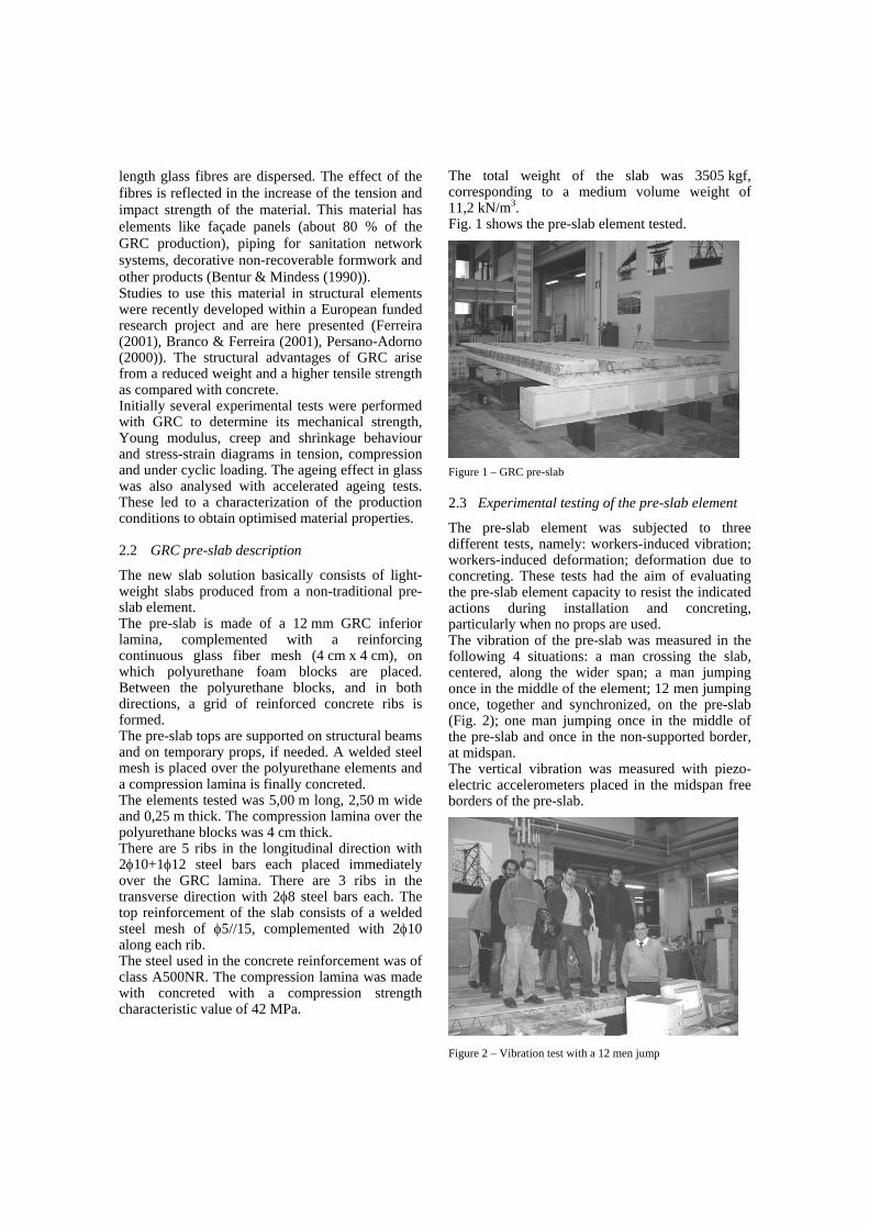
The pre-slab element was subjected to three different tests, namely: workers-induced vibration; workers-induced deformation; deformation due to concreting. These tests had the aim of evaluating the pre-slab element capacity to resist the indicated actions during installation and concreting, particularly when no props are used. The vibration of the pre-slab was measured in the following 4 situations: a man crossing the slab, centered, along the wider span; a man jumping once in the middle of the element; 12 men jumping once, together and synchronized, on the pre-slab (Fig. 2); one man jumping once in the middle of the pre-slab and once in the non-supported border, at midspan. The vertical vibration was measured with piezo-electric accelerometers placed in the midspan free borders of the pre-slab.
Figure 2 – Vibration test with a 12 men jump

The FFT algorithm was applied to the first three tests, in a zone of free oscillation (with no dynamic action of the walking/jumping men), in order to obtain the natural vibrating frequencies of the pre-slab. From the analysis of the dynamic tests results the following aspects are pointed out: - The maximum oscillation values are 0,34 mm in the first test, 1,41 mm in the second (Fig. 3), 5,69 in the third and 1,95 mm in the 4th; - The first natural frequency of the pre-slab, obtained with the FFT algorithm, was worth 8,0 Hz to 8,4 Hz (Fig. 4); - The structural damping factor is about 5% (Fig. 5), as in the cracked concrete structures; because the pre-slab is not expected to be cracked under the imposed actions, it can be concluded that this increase of the damping factor, when compared to the 2% of non-cracked concrete, may be due to the presence of the polyurethane foam; - The level of vibrations induced is clearly felt by the persons however it is not particularly disturbing
-1.50
-1.00
-0.50
0.00
0.50
1.00
1.50
0 1 2 3 4 5
Time (s)
Dis
plac
emen
t (m
m)
Figure 3 – Partial record of the first dynamic test (one man jump)
0.0
0.5
1.0
1.5
2.0
2.5
3.0
3.5
0 5 10 15 20 25Frequency (Hz)
Spe
ctra
l val
ue (m
m^2
/Hz)
f = 8,2 Hz
Figure 4 – FFT obtained in the second test.
-0.50
-0.30
-0.10
0.10
0.30
0.50
2 3 4
Time (s)
Dis
plac
emen
t (m
m)
ξ = 5%
ξ = 5%
Figure 5 – Damping factor obtained in free oscillation after a
one man jump
The deformation of the pre-slab induced by the workers was measured in the following 2 situations: 12 men in the center of the pre-slab; 1 man in the center and in the free border of the pre-slab. During the tests the midspan displacement in both free borders of the pre-slab were measured by means of resistive displacement transducers of 0,01 mm precision. In the first test a maximum value of 7,0 mm was measured while in the second one a maximum of 0,6 mm was obtained while the men was centered and of 1,2 mm at one border when the man was near that border, in the midspan. In both tests a practically fully elastic recuperation was observed. Although the results show a good structural behavior of the pre-slab during construction some polyurethane blocks were partially damaged and a reinforcing solution must be implemented (for example, using massive instead of voided blocks, since their weight will not substantially increase). The results of the vibration and deformation tests described show that for the construction phase the pre-slab is viable. During the concreting of the compression lamina the slab was only supported at its ends (two parallel supporting steel beams 4,70 m distant from each other), without props, although these shall be used in practical cases. The purpose of this procedure was to evaluate the pre-slab capacity to resist the concrete weight and to measure its deformation under such circumstances that may accidentally happen during construction. This may be regarded as a non-destructive load-test of the pre-slab. For this purposes the vertical displacements were measured in the midspan, in both lateral borders and in the center of the slab. Immediately after concreting the slab was forced into the original (before concreting) position and props were placed under the slab.
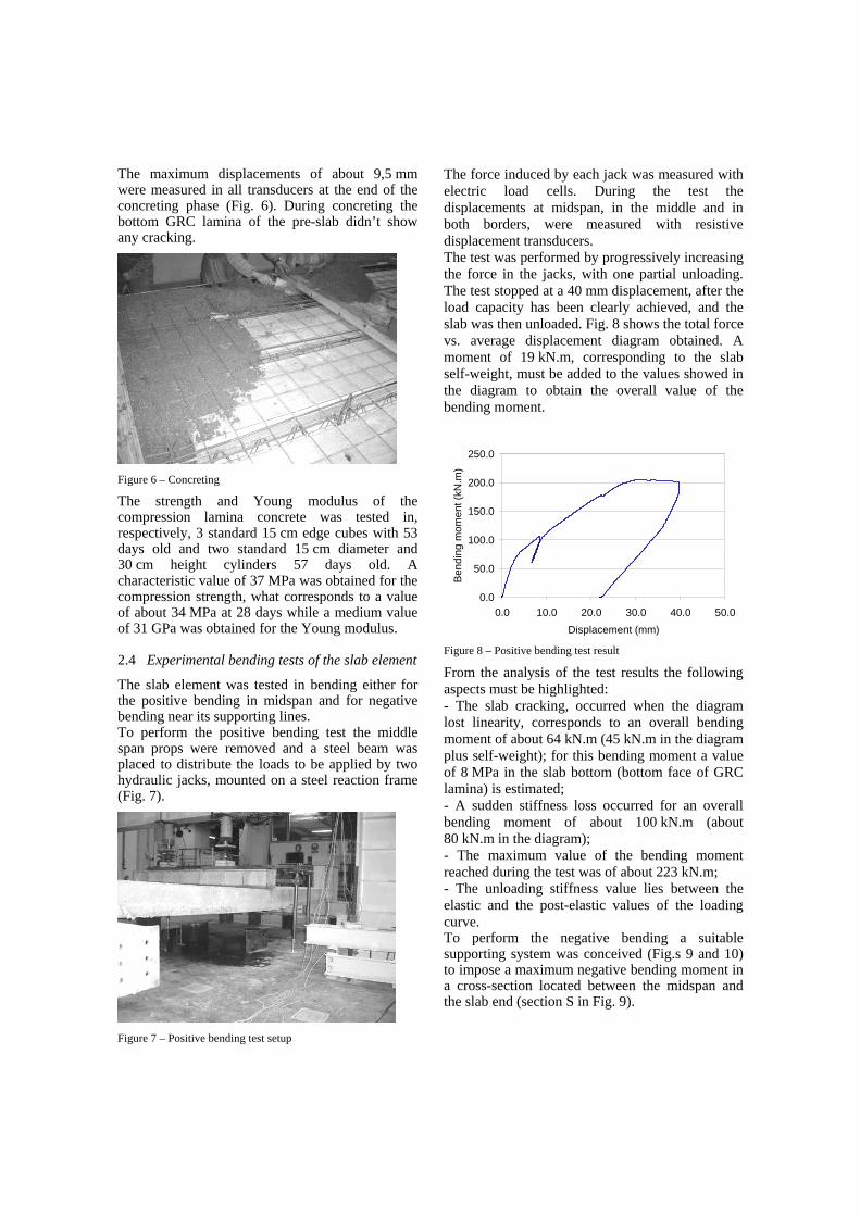
The maximum displacements of about 9,5 mm were measured in all transducers at the end of the concreting phase (Fig. 6). During concreting the bottom GRC lamina of the pre-slab didn’t show any cracking.
Figure 6 – Concreting
The strength and Young modulus of the compression lamina concrete was tested in, respectively, 3 standard 15 cm edge cubes with 53 days old and two standard 15 cm diameter and 30 cm height cylinders 57 days old. A characteristic value of 37 MPa was obtained for the compression strength, what corresponds to a value of about 34 MPa at 28 days while a medium value of 31 GPa was obtained for the Young modulus.
2.4 Experimental bending tests of the slab element
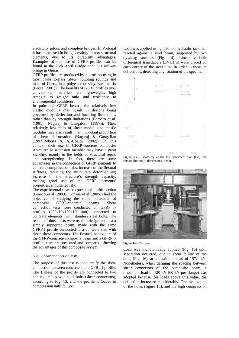
The slab element was tested in bending either for the positive bending in midspan and for negative bending near its supporting lines. To perform the positive bending test the middle span props were removed and a steel beam was placed to distribute the loads to be applied by two hydraulic jacks, mounted on a steel reaction frame (Fig. 7).
Figure 7 – Positive bending test setup
The force induced by each jack was measured with electric load cells. During the test the displacements at midspan, in the middle and in both borders, were measured with resistive displacement transducers. The test was performed by progressively increasing the force in the jacks, with one partial unloading. The test stopped at a 40 mm displacement, after the load capacity has been clearly achieved, and the slab was then unloaded. Fig. 8 shows the total force vs. average displacement diagram obtained. A moment of 19 kN.m, corresponding to the slab self-weight, must be added to the values showed in the diagram to obtain the overall value of the bending moment.
0.0
50.0
100.0
150.0
200.0
250.0
0.0 10.0 20.0 30.0 40.0 50.0Displacement (mm)
Ben
ding
mom
ent (
kN.m
)
Figure 8 – Positive bending test result
From the analysis of the test results the following aspects must be highlighted: - The slab cracking, occurred when the diagram lost linearity, corresponds to an overall bending moment of about 64 kN.m (45 kN.m in the diagram plus self-weight); for this bending moment a value of 8 MPa in the slab bottom (bottom face of GRC lamina) is estimated; - A sudden stiffness loss occurred for an overall bending moment of about 100 kN.m (about 80 kN.m in the diagram); - The maximum value of the bending moment reached during the test was of about 223 kN.m; - The unloading stiffness value lies between the elastic and the post-elastic values of the loading curve. To perform the negative bending a suitable supporting system was conceived (Fig.s 9 and 10) to impose a maximum negative bending moment in a cross-section located between the midspan and the slab end (section S in Fig. 9).

(m)5,00
0,12 2,24 0,30 0,30 0,91 0,30 0,11
F1
F
S
LAJE
δ
0,72
SLAB
Figure 9 – Test setup scheme for negative bending The force F to produce the negative bending moment at section S was equally applied by two hydraulic jacks mounted on the reaction frame. The displacement δ was measured in two points of the cross section with electric transducers.
Figure 10 – Test setup for negative bending
A complementary hydraulic jack was used to apply a force F1 at the free end of the cantilever (Fig. 11) in order to release the props used in the mounting phase.
Figure 11– Cantilever in negative bending
The test procedure considered the monotonically application of the negative bending moment at section S. Fig. 12 shows the moment vs. average
displacement diagram obtained in the test. The negative bending is represented with positive values for an easier reading. The initial phase corresponds to the application and release of force in the complementary jack. The values plotted in the diagram do not include the self-weight action, which induce a negative moment of 39 kN.m.
-50.0
0.0
50.0
100.0
150.0
200.0
-5.0 5.0 15.0 25.0 35.0 45.0
Displacement (mm)
Ben
ding
mom
ent (
kN.m
)
Figure 12 – Negative bending test result
The following points must be highlighted when analyzing the test results: - A sudden stiffness lost occurred for an overall moment value of about 139 kN.m (100 kN.m in the diagram); - The maximum value attained was 173 kN.m (134 kN.m in the diagram), corresponding to the formation of cracks with significant openings, what must be considered as the collapse occurrence; - After that the displacement transducers were dismounted for safety reasons and the hydraulic jacks continued to actuate (this phase is not represented because there was no displacement readings) but the moment value did not increase. With these tests, this new structural solution showed is efficiency and viability for slabs rehabilitation with a big advantage for seismic rehabilitation due to its lightness.
3 GFRP-CONCRETE COMPOSITE BEAMS
3.1 Main characteristics of GFRP profiles
Until recently, advanced composite materials were used in structures requiring high performance standards, such as those from the aerospace industry. The development of the fibre reinforced plastic industry enabled the expansion to other markets, such as the construction industry, and they are now used in a variety of structural engineering applications ranging from simple beams, columns, trusses and floor panels to lighthouse towers,
electricity pilons and complete bridges. In Portugal it has been used in bridges mainly in non structural elements, due to its durability advantages. Examples of this use of GFRP profiles can be found in the 25th April Bridge and in a railway bridge in Oeiras. GFRP profiles are produced by pultrusion using in most cases E-glass fibers, coupling rovings and mats of fibers, in a polyester or vinylester matrix (Pecce (2001)). The benefits of GFRP profiles over conventional materials are lightweight, high strength to weight ratio and resistance to environmental conditions. In pultruded GFRP beams, the relatively low elastic modulus may result in designs being governed by deflection and buckling limitations, rather than by strength limitations (Barbero et al. (1991), Nagaraj & GangaRao (1997)). Their relatively low ratio of shear modulus to tensile modulus may also result in an important proportion of shear deformation (Nagaraj & GangaRao (1997)Roberts & Al-Ubaidi (2002)). In this context, their use in GFRP-concrete composite structures as a tension member may have a great viability, mainly in the fields of structural repair and strengthening. In fact, there are some advantages in the connection of GFRP elements to concrete compression slabs: increase of the flexural stiffness, reducing the structure’s deformability; increase of the structure’s strength capacity, making good use of the GFRP elements’ properties, simultaneously. The experimental research presented in this section (Branco et al (2003), Correia et al (2005)) had the objective of studying the static behaviour of composite GFRP-concrete beams. Shear connection tests were conducted on GFRP I-profiles (200x10x100x10 mm) connected to concrete elements, with stainless steel bolts. The results of those tests were used to design and test a simply supported beam, made with the same GFRP-I profile connected to a concrete slab with those shear connectors. The flexural behaviours of the GFRP-concrete composite beam and a GFRP I-profile beam are presented and compared, showing the advantages of this composite system.
3.2 Shear connection tests
The purpose of this test is to quantify the shear connection between concrete and a GFRP I-profile. The flanges of the profile are connected to two concrete cubes with steel bolts (shear connectors), according to Fig. 13, and the profile is loaded in compression until failure.
Load was applied using a 20 ton hydraulic jack that reacted against a steel beam, supported by two dywidag anchors (Fig. 14). Linear variable differential transducers (LVDT’s) were placed on each corner of the steel plate in order to measure deflections, detecting any rotation of the specimen.
Figure 13 – Geometry of the test specimen: plan (top) and section (bottom) - dimensions in mm.
Figure 14 – Test setup
Load was monotonically applied (Fig. 15) until separation occurred, due to shear failure of the bolts (Fig. 16), at a maximum load of 157,1 kN. Nonetheless, when defining the spacing between shear connectors of the composite beam, a maximum load of 120 kN (60 kN per flange) was adopted because, for loads above this value, the deflection increased considerably. The ovalization of the holes (figure 16), and the high compression

stress determined for the region in front of the bolts, suggest that bearing failure of the flanges was imminent.
0
20
40
60
80
100
120
140
160
180
0 1 2 3 4 5 6 7Deflection (mm)
Loa
d (k
N)
Figure 15 – Load versus deflection
Figure 16 – Shear failure of the bolts and ovalization of holes
3.3 Analysis of GFRP-concrete composite beams
The elastic analysis of the GFRP-concrete section (figure 17) assumes the validity of the following hypotheses: Concrete has no resistance to tension stresses; Bernoulli’s principle is valid; There is no slipping between the profile and the concrete slab; The whole width of the concrete slab is effective; The contribution of the concrete slab’s steel reinforcement is not considered.
εp
εf2
εw
εf1
εεc
Figure 17 – Geometry of the GRRP-concrete composite beam’s section and axial extensions distribution. The neutral axis’ position (Xe) is determined considering the previous hypotheses and the fact that it crosses the centroid of the homogenised section. Assuming that the neutral axis lies on the concrete slab (i.e., Xe < hc), the following expressions can be used to compute its position and the section’s equivalent inertia (Ieq),
02hhAn2XAn2Xb cpep
2ec =⎟
⎠⎞
⎜⎝⎛ +×××−×××+×
2
ecpp
3ec
eq X2hhAI
n3XbI ⎟
⎠⎞
⎜⎝⎛ −+×++
××
=
where, n – quotient between the profile’s (longitudinal, Ep) and concrete’s (Ec) elastic moduli; Ap – profile’s cross section; Ip – profile’s inertia in the major principal axis. In order to compute the ultimate flexural strength of GFRP-concrete composite sections, the following hypotheses are added to the previous ones: The profile can be elastically loaded in tension to a stress value of σtu,x; Concrete’s effective area can be loaded in compression to a stress value of fc. Design of the cross section is made imposing the following additional conditions (figure 14): Compression failure occurs on the top of the concrete slab (σc = fc), for an extension εc = 0,0035; Neutral axis in failure lies on the concrete slab.
The first additional condition is placed because the concrete’s compressive failure is a more ductile mechanism than the tension failure of the profile. The second condition aims a better exploitation of the profile’s mechanical properties.
εg
εf2 σf2
εw σw
σf1εf1
εεc = 0,0035
σσc = fc
Figure 18 – Axial extension and stress distributions in failure The neutral axis’ position is determined imposing the static conditions in the section, i.e., providing that the compressive force on the concrete slab is balanced by the tension forces on the different elements (top flange, web and bottom flange) of the profile:
( ) 02hHAhH2AXAAX
Efb80
wfewf2e
cp
cc =⎥⎦
⎤⎢⎣
⎡⎟⎠⎞
⎜⎝⎛ −×+−××−×++×
ε××× )(,
Ultimate flexural strength of the composite section is determined imposing section moment equilibrium:
( ) ( ) ( ) +⎟⎠⎞
⎜⎝⎛ +−−×××ε×+×××××=
2thXHbtEX60fXb80M f
ef1bpececu ,,
( )[ ] ( ) ⎟⎠⎞
⎜⎝⎛ −−×××ε×+⎟
⎠⎞
⎜⎝⎛ −−××−××ε×+
2tXHbtE
2hXHt2htE f
ef2bpefwwp
In a simply supported GFRP-concrete composite beam (with a span length L), that fails in compression, the maximum shear load between the midspan and each one of the supports is equal to the maximum compressive load in the concrete slab (Fc). Considering the maximum connection load obtained in the shear connection test (Fmax,test), the spacing between sections with shear connectors (af,c), necessary to provide full interaction between the two materials (preventing slippage between the profile and the concrete slab), can be estimated with the following expression:
2/
, max,
LF
Faf
c
testc =
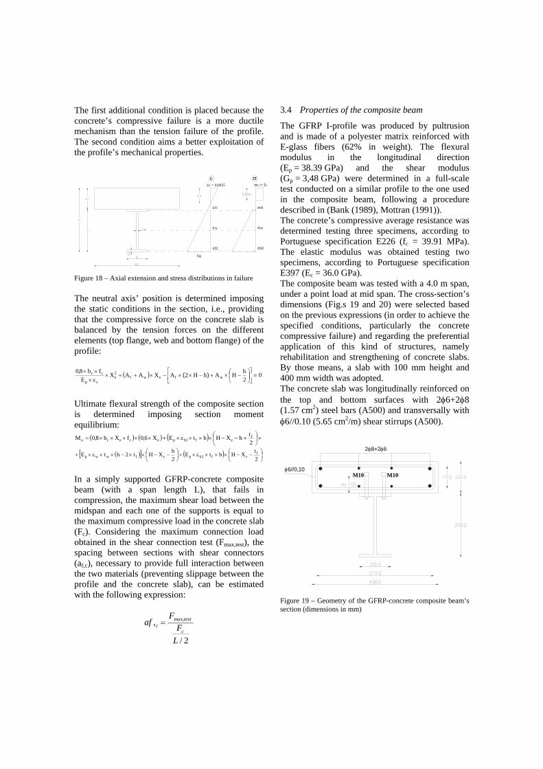
3.4 Properties of the composite beam
The GFRP I-profile was produced by pultrusion and is made of a polyester matrix reinforced with E-glass fibers (62% in weight). The flexural modulus in the longitudinal direction (Ep = 38.39 GPa) and the shear modulus (Gp = 3,48 GPa) were determined in a full-scale test conducted on a similar profile to the one used in the composite beam, following a procedure described in (Bank (1989), Mottran (1991)). The concrete’s compressive average resistance was determined testing three specimens, according to Portuguese specification E226 (fc = 39.91 MPa). The elastic modulus was obtained testing two specimens, according to Portuguese specification E397 (Ec = 36.0 GPa). The composite beam was tested with a 4.0 m span, under a point load at mid span. The cross-section’s dimensions (Fig.s 19 and 20) were selected based on the previous expressions (in order to achieve the specified conditions, particularly the concrete compressive failure) and regarding the preferential application of this kind of structures, namely rehabilitation and strengthening of concrete slabs. By those means, a slab with 100 mm height and 400 mm width was adopted. The concrete slab was longitudinally reinforced on the top and bottom surfaces with 2φ6+2φ8 (1.57 cm2) steel bars (A500) and transversally with φ6//0.10 (5.65 cm2/m) shear stirrups (A500).
φ6//0,10 M10 M10
2φ8+2φ6
Figure 19 – Geometry of the GFRP-concrete composite beam’s section (dimensions in mm)

Figure 20 – Bolts placed on the profile’s top flange
Elastic neutral axis (Xe,elastic), equivalent flexural rigidity (EI,eq), neutral axis in failure (Xe,failure) and flexural strength (Mu) of the composite section were computed using expressions (1-4) and the experimental values of the mechanical properties of the concrete and the GFRP profile: Xe,elastic = 53.78 mm (verifying Xe < hc); I,eq = 4639.61 kN.m2; Xe,failure = 70.93 mm (verifying Xe < hc); Mu = 188.49 kN.m The shear connection test result (maximum shear load of 60 kN for a bolted section) and the maximum shear force (corresponding to the resistance of the compressed region of the concrete slab) were used to establish the connectors spacing of 12,5 cm, using expression (5).
3.5 Bending test of a GFRP-concrete composite beam
Each end support of the beam was mounted on a 5 cm diameter cylinder bearing placed on the top of a metallic thick plate. Both supports allowed free rotation and one of them allowed sliding. Small tubular profiles were welded on each side of the metallic plates and, without touching the composite beam during the test, they prevented its fall by lateral rotation after failure. Load was applied at the midspan of the composite beam by a 30 ton hydraulic jack in a self-straining test frame (Fig. 21). Load was applied to the concrete slab via 8 cm wide steel spreader plate and the load was measured by a 30 ton capacity load cell, placed between the hydraulic jack and the test profile. LVDT’s and strain gauges were used in different
positions of sections S1 to S4 (Fig. 22). LVDT δ1 was used in section S1 to measure deflections under the applied load, δ2 and δ3 were mounted horizontally in section S2 to verify the existence of slipping between the two materials, and δ4 and δ5 were mounted in section S3 to detect an eventual beam’s lateral rotation. To overcome the stress concentration effects and complexity of stress distribution near the load application point, strain gauges (ε1 a ε8) were mounted in section S4, at a distance of 30 cm from the load application point.
Figure 21 – Self-straining test frame S3 S1 S4 S2
δ2δ3
Deflectómetro (horizontal)
Deflectómetro (vertical)
Extensómetro
δ1
ε2ε1
δ5δ4
ε4ε3
ε6ε5
ε7 ε8
Displacement (vertical)
Displacement (horizontal)
Strain
Figure 22 – Beam instrumentation
Test occurred at 28 days and two load controlled cycles were accomplished. In both load cycles
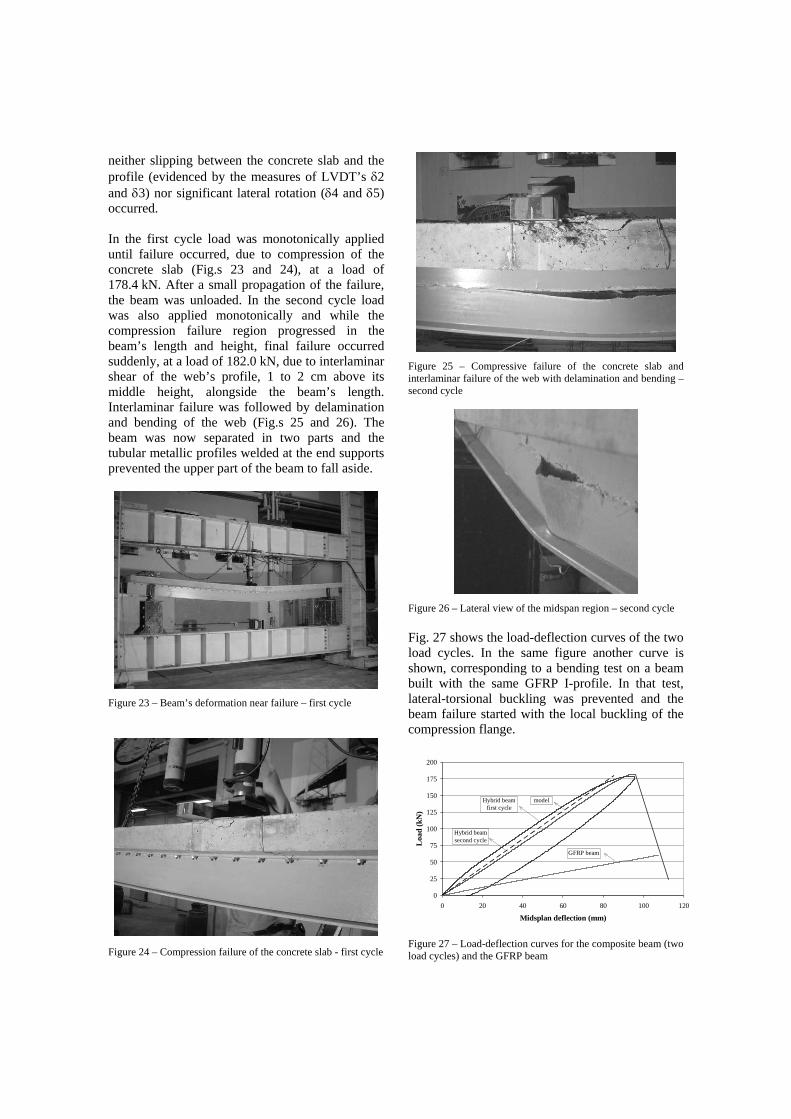
neither slipping between the concrete slab and the profile (evidenced by the measures of LVDT’s δ2 and δ3) nor significant lateral rotation (δ4 and δ5) occurred. In the first cycle load was monotonically applied until failure occurred, due to compression of the concrete slab (Fig.s 23 and 24), at a load of 178.4 kN. After a small propagation of the failure, the beam was unloaded. In the second cycle load was also applied monotonically and while the compression failure region progressed in the beam’s length and height, final failure occurred suddenly, at a load of 182.0 kN, due to interlaminar shear of the web’s profile, 1 to 2 cm above its middle height, alongside the beam’s length. Interlaminar failure was followed by delamination and bending of the web (Fig.s 25 and 26). The beam was now separated in two parts and the tubular metallic profiles welded at the end supports prevented the upper part of the beam to fall aside.
Figure 23 – Beam’s deformation near failure – first cycle
Figure 24 – Compression failure of the concrete slab - first cycle
Figure 25 – Compressive failure of the concrete slab and interlaminar failure of the web with delamination and bending – second cycle
Figure 26 – Lateral view of the midspan region – second cycle Fig. 27 shows the load-deflection curves of the two load cycles. In the same figure another curve is shown, corresponding to a bending test on a beam built with the same GFRP I-profile. In that test, lateral-torsional buckling was prevented and the beam failure started with the local buckling of the compression flange.
0
25
50
75
100
125
150
175
200
0 20 40 60 80 100 120
Midsplan deflection (mm)
Loa
d (k
N)
Hybrid beamfirst cycle
Hybrid beamsecond cycle
GFRP beam
model
Figure 27 – Load-deflection curves for the composite beam (two load cycles) and the GFRP beam
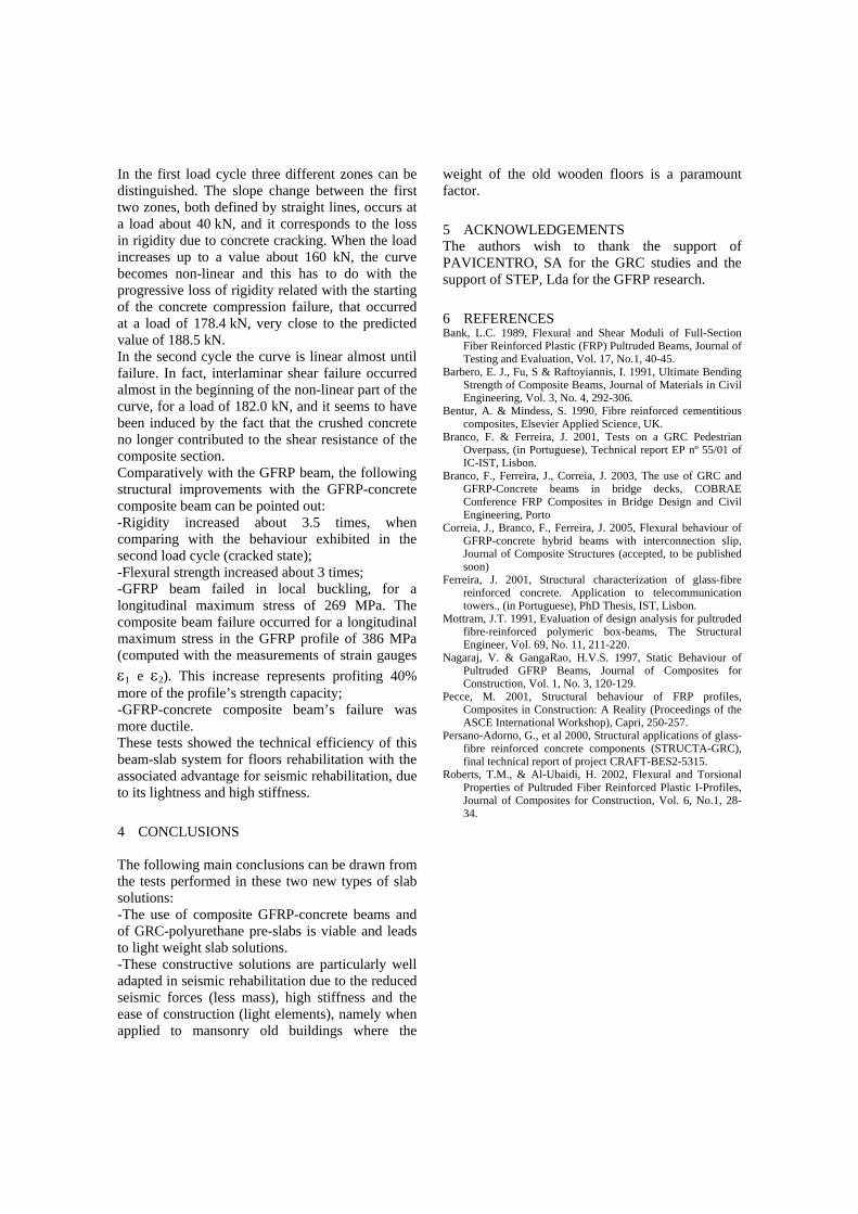
In the first load cycle three different zones can be distinguished. The slope change between the first two zones, both defined by straight lines, occurs at a load about 40 kN, and it corresponds to the loss in rigidity due to concrete cracking. When the load increases up to a value about 160 kN, the curve becomes non-linear and this has to do with the progressive loss of rigidity related with the starting of the concrete compression failure, that occurred at a load of 178.4 kN, very close to the predicted value of 188.5 kN. In the second cycle the curve is linear almost until failure. In fact, interlaminar shear failure occurred almost in the beginning of the non-linear part of the curve, for a load of 182.0 kN, and it seems to have been induced by the fact that the crushed concrete no longer contributed to the shear resistance of the composite section. Comparatively with the GFRP beam, the following structural improvements with the GFRP-concrete composite beam can be pointed out: -Rigidity increased about 3.5 times, when comparing with the behaviour exhibited in the second load cycle (cracked state); -Flexural strength increased about 3 times; -GFRP beam failed in local buckling, for a longitudinal maximum stress of 269 MPa. The composite beam failure occurred for a longitudinal maximum stress in the GFRP profile of 386 MPa (computed with the measurements of strain gauges ε1 e ε2). This increase represents profiting 40% more of the profile’s strength capacity; -GFRP-concrete composite beam’s failure was more ductile. These tests showed the technical efficiency of this beam-slab system for floors rehabilitation with the associated advantage for seismic rehabilitation, due to its lightness and high stiffness.
4 CONCLUSIONS The following main conclusions can be drawn from the tests performed in these two new types of slab solutions: -The use of composite GFRP-concrete beams and of GRC-polyurethane pre-slabs is viable and leads to light weight slab solutions. -These constructive solutions are particularly well adapted in seismic rehabilitation due to the reduced seismic forces (less mass), high stiffness and the ease of construction (light elements), namely when applied to mansonry old buildings where the
weight of the old wooden floors is a paramount factor.
5 ACKNOWLEDGEMENTS The authors wish to thank the support of PAVICENTRO, SA for the GRC studies and the support of STEP, Lda for the GFRP research.
6 REFERENCES Bank, L.C. 1989, Flexural and Shear Moduli of Full-Section
Fiber Reinforced Plastic (FRP) Pultruded Beams, Journal of Testing and Evaluation, Vol. 17, No.1, 40-45.
Barbero, E. J., Fu, S & Raftoyiannis, I. 1991, Ultimate Bending Strength of Composite Beams, Journal of Materials in Civil Engineering, Vol. 3, No. 4, 292-306.
Bentur, A. & Mindess, S. 1990, Fibre reinforced cementitious composites, Elsevier Applied Science, UK.
Branco, F. & Ferreira, J. 2001, Tests on a GRC Pedestrian Overpass, (in Portuguese), Technical report EP nº 55/01 of IC-IST, Lisbon.
Branco, F., Ferreira, J., Correia, J. 2003, The use of GRC and GFRP-Concrete beams in bridge decks, COBRAE Conference FRP Composites in Bridge Design and Civil Engineering, Porto
Correia, J., Branco, F., Ferreira, J. 2005, Flexural behaviour of GFRP-concrete hybrid beams with interconnection slip, Journal of Composite Structures (accepted, to be published soon)
Ferreira, J. 2001, Structural characterization of glass-fibre reinforced concrete. Application to telecommunication towers., (in Portuguese), PhD Thesis, IST, Lisbon.
Mottram, J.T. 1991, Evaluation of design analysis for pultruded fibre-reinforced polymeric box-beams, The Structural Engineer, Vol. 69, No. 11, 211-220.
Nagaraj, V. & GangaRao, H.V.S. 1997, Static Behaviour of Pultruded GFRP Beams, Journal of Composites for Construction, Vol. 1, No. 3, 120-129.
Pecce, M. 2001, Structural behaviour of FRP profiles, Composites in Construction: A Reality (Proceedings of the ASCE International Workshop), Capri, 250-257.
Persano-Adorno, G., et al 2000, Structural applications of glass-fibre reinforced concrete components (STRUCTA-GRC), final technical report of project CRAFT-BES2-5315.
Roberts, T.M., & Al-Ubaidi, H. 2002, Flexural and Torsional Properties of Pultruded Fiber Reinforced Plastic I-Profiles, Journal of Composites for Construction, Vol. 6, No.1, 28-34.


![GFRP [Hand lay up]](https://static.fdocuments.net/doc/165x107/557cb1dcd8b42abf328b4c0e/gfrp-hand-lay-up.jpg)


![GFRP [Resin Infusion]](https://static.fdocuments.net/doc/165x107/546e67d4af795971298b5642/gfrp-resin-infusion.jpg)