Supplementary Cementitious Materials
13
Supplementary cementitious materials Barbara Lothenbach a, ⁎, Karen Scrivener b , R.D. Hooton c a Empa, Laboratory for Concrete & Construction Chemistry, CH-8600 Dübendorf, Switzerland b EPFL, Laboratory of Construction Materials, CH-1015 Lausanne, Switzerland c University of Toronto, Dept. of Civil Engineering, Toronto, Canada, M5S 1A4 abstract article info Article history: Received 1 October 2010 Accepted 1 December 2010 Keywords: Blended cements [D] Supplementary cementitious material [D] Thermodynamics [B] Hydrates [B] Kinetic [C] The use of silica rich SCMs influences the amount and kind of hydrates formed and thus the volume, the porosity and finally the durability of these materials. At the levels of substitution normally used, major changes are the lower Ca/Si ratio in the C–S–H phase and consumption of portlandite. Alumina-rich SCMs increase the Al-uptake in C–S–H and the amounts of aluminate containing hydrates. In general the changes in phase assemblages are well captured by thermodynamic modelling, although better knowledge of the C–S–H is needed. At early ages, “filler” effects lead to an increased reaction of the clinker phases. Reaction of SCMs starts later and is enhanced with pH and temperature. Composition, fineness and the amount of glassy phase play also an important role. Due to the diverse range of SCM used, generic relations between composition, particle size, exposure conditions as temperature or relative humidity become increasingly crucial. © 2010 Elsevier Ltd. All rights reserved. Contents 1. Introduction . . . . . . . . . . . . . . . . . . . . . . . . . . . . . . . . . . . . . . . . . . . . . . . . . . . . . . . . . . . . . 1245 2. Phase assemblages and thermodynamic modelling . . . . . . . . . . . . . . . . . . . . . . . . . . . . . . . . . . . . . . . . . . . 1245 2.1. Characteristics of C–S–H in blended cements . . . . . . . . . . . . . . . . . . . . . . . . . . . . . . . . . . . . . . . . . . 1246 2.2. PC–silica fume . . . . . . . . . . . . . . . . . . . . . . . . . . . . . . . . . . . . . . . . . . . . . . . . . . . . . . . . . 1246 2.3. PC–fly ash . . . . . . . . . . . . . . . . . . . . . . . . . . . . . . . . . . . . . . . . . . . . . . . . . . . . . . . . . . . 1247 2.4. PC–slag . . . . . . . . . . . . . . . . . . . . . . . . . . . . . . . . . . . . . . . . . . . . . . . . . . . . . . . . . . . . 1248 3. Kinetics . . . . . . . . . . . . . . . . . . . . . . . . . . . . . . . . . . . . . . . . . . . . . . . . . . . . . . . . . . . . . . . 1249 3.1. Filler effect . . . . . . . . . . . . . . . . . . . . . . . . . . . . . . . . . . . . . . . . . . . . . . . . . . . . . . . . . . 1249 3.2. Techniques to measure the reaction of SCMs . . . . . . . . . . . . . . . . . . . . . . . . . . . . . . . . . . . . . . . . . . 1250 3.3. Influence of different factors on reaction rate . . . . . . . . . . . . . . . . . . . . . . . . . . . . . . . . . . . . . . . . . . 1251 3.3.1. Composition of the SCM . . . . . . . . . . . . . . . . . . . . . . . . . . . . . . . . . . . . . . . . . . . . . . . . 1251 3.3.2. Replacement level . . . . . . . . . . . . . . . . . . . . . . . . . . . . . . . . . . . . . . . . . . . . . . . . . . . 1252 3.3.3. Solution pH . . . . . . . . . . . . . . . . . . . . . . . . . . . . . . . . . . . . . . . . . . . . . . . . . . . . . . 1252 3.3.4. Temperature . . . . . . . . . . . . . . . . . . . . . . . . . . . . . . . . . . . . . . . . . . . . . . . . . . . . . 1252 3.4. PC–silica fume . . . . . . . . . . . . . . . . . . . . . . . . . . . . . . . . . . . . . . . . . . . . . . . . . . . . . . . . . 1252 3.5. PC–fly ash . . . . . . . . . . . . . . . . . . . . . . . . . . . . . . . . . . . . . . . . . . . . . . . . . . . . . . . . . . . 1252 3.6. PC–slag . . . . . . . . . . . . . . . . . . . . . . . . . . . . . . . . . . . . . . . . . . . . . . . . . . . . . . . . . . . . 1252 4. Liquid phase . . . . . . . . . . . . . . . . . . . . . . . . . . . . . . . . . . . . . . . . . . . . . . . . . . . . . . . . . . . . . 1252 4.1. Changes in pore solution composition . . . . . . . . . . . . . . . . . . . . . . . . . . . . . . . . . . . . . . . . . . . . . . 1252 4.2. Long-term alkalinity . . . . . . . . . . . . . . . . . . . . . . . . . . . . . . . . . . . . . . . . . . . . . . . . . . . . . . 1253 5. Summary and perspectives . . . . . . . . . . . . . . . . . . . . . . . . . . . . . . . . . . . . . . . . . . . . . . . . . . . . . . 1253 Acknowledgements . . . . . . . . . . . . . . . . . . . . . . . . . . . . . . . . . . . . . . . . . . . . . . . . . . . . . . . . . . . . 1253 Appendix A. Thermodynamic modelling . . . . . . . . . . . . . . . . . . . . . . . . . . . . . . . . . . . . . . . . . . . . . . . . . 1253 A.1. Basics of thermodynamic modelling . . . . . . . . . . . . . . . . . . . . . . . . . . . . . . . . . . . . . . . . . . . . . . . 1253 A.2. C–S–H. . . . . . . . . . . . . . . . . . . . . . . . . . . . . . . . . . . . . . . . . . . . . . . . . . . . . . . . . . . . . 1254 A.3. Thermodynamic modelling of hydrated systems . . . . . . . . . . . . . . . . . . . . . . . . . . . . . . . . . . . . . . . . . 1254 References . . . . . . . . . . . . . . . . . . . . . . . . . . . . . . . . . . . . . . . . . . . . . . . . . . . . . . . . . . . . . . . . 1254 Cement and Concrete Research 41 (2011) 1244–1256 ⁎ Corresponding author. E-mail address: [email protected] (B. Lothenbach). 0008-8846/$ – see front matter © 2010 Elsevier Ltd. All rights reserved. doi:10.1016/j.cemconres.2010.12.001 Contents lists available at ScienceDirect Cement and Concrete Research journal homepage: http://ees.elsevier.com/CEMCON/default.asp
description
review on different SCMs
Transcript of Supplementary Cementitious Materials
Cement and Concrete Research 41 (2011) 1244–1256
Contents lists available at ScienceDirect
Cement and Concrete Research
j ourna l homepage: ht tp: / /ees.e lsev ie r.com/CEMCON/defau l t .asp
Supplementary cementitious materials
Barbara Lothenbach a,⁎, Karen Scrivener b, R.D. Hooton c
a Empa, Laboratory for Concrete & Construction Chemistry, CH-8600 Dübendorf, Switzerlandb EPFL, Laboratory of Construction Materials, CH-1015 Lausanne, Switzerlandc University of Toronto, Dept. of Civil Engineering, Toronto, Canada, M5S 1A4
⁎ Corresponding author.E-mail address: [email protected] (B. Lo
0008-8846/$ – see front matter © 2010 Elsevier Ltd. Aldoi:10.1016/j.cemconres.2010.12.001
a b s t r a c t
a r t i c l e i n f oArticle history:Received 1 October 2010Accepted 1 December 2010
Keywords:Blended cements [D]Supplementary cementitious material [D]Thermodynamics [B]Hydrates [B]Kinetic [C]
The use of silica rich SCMs influences the amount and kind of hydrates formed and thus the volume, the porosityand finally the durability of these materials. At the levels of substitution normally used, major changes are thelower Ca/Si ratio in the C–S–H phase and consumption of portlandite. Alumina-rich SCMs increase the Al-uptakein C–S–H and the amounts of aluminate containing hydrates. In general the changes in phase assemblages arewell captured by thermodynamic modelling, although better knowledge of the C–S–H is needed.At early ages, “filler” effects lead to an increased reaction of the clinker phases. Reaction of SCMs starts later andis enhanced with pH and temperature. Composition, fineness and the amount of glassy phase play also animportant role. Due to the diverse range of SCM used, generic relations between composition, particle size,exposure conditions as temperature or relative humidity become increasingly crucial.
thenbach).
l rights reserved.
© 2010 Elsevier Ltd. All rights reserved.
Contents
1. Introduction . . . . . . . . . . . . . . . . . . . . . . . . . . . . . . . . . . . . . . . . . . . . . . . . . . . . . . . . . . . . . 12452. Phase assemblages and thermodynamic modelling . . . . . . . . . . . . . . . . . . . . . . . . . . . . . . . . . . . . . . . . . . . 1245
2.1. Characteristics of C–S–H in blended cements . . . . . . . . . . . . . . . . . . . . . . . . . . . . . . . . . . . . . . . . . . 12462.2. PC–silica fume . . . . . . . . . . . . . . . . . . . . . . . . . . . . . . . . . . . . . . . . . . . . . . . . . . . . . . . . . 12462.3. PC–fly ash . . . . . . . . . . . . . . . . . . . . . . . . . . . . . . . . . . . . . . . . . . . . . . . . . . . . . . . . . . . 12472.4. PC–slag . . . . . . . . . . . . . . . . . . . . . . . . . . . . . . . . . . . . . . . . . . . . . . . . . . . . . . . . . . . . 1248
3. Kinetics . . . . . . . . . . . . . . . . . . . . . . . . . . . . . . . . . . . . . . . . . . . . . . . . . . . . . . . . . . . . . . . 12493.1. Filler effect . . . . . . . . . . . . . . . . . . . . . . . . . . . . . . . . . . . . . . . . . . . . . . . . . . . . . . . . . . 12493.2. Techniques to measure the reaction of SCMs . . . . . . . . . . . . . . . . . . . . . . . . . . . . . . . . . . . . . . . . . . 12503.3. Influence of different factors on reaction rate . . . . . . . . . . . . . . . . . . . . . . . . . . . . . . . . . . . . . . . . . . 1251
3.3.1. Composition of the SCM . . . . . . . . . . . . . . . . . . . . . . . . . . . . . . . . . . . . . . . . . . . . . . . . 12513.3.2. Replacement level . . . . . . . . . . . . . . . . . . . . . . . . . . . . . . . . . . . . . . . . . . . . . . . . . . . 12523.3.3. Solution pH . . . . . . . . . . . . . . . . . . . . . . . . . . . . . . . . . . . . . . . . . . . . . . . . . . . . . . 12523.3.4. Temperature . . . . . . . . . . . . . . . . . . . . . . . . . . . . . . . . . . . . . . . . . . . . . . . . . . . . . 1252
3.4. PC–silica fume . . . . . . . . . . . . . . . . . . . . . . . . . . . . . . . . . . . . . . . . . . . . . . . . . . . . . . . . . 12523.5. PC–fly ash . . . . . . . . . . . . . . . . . . . . . . . . . . . . . . . . . . . . . . . . . . . . . . . . . . . . . . . . . . . 12523.6. PC–slag . . . . . . . . . . . . . . . . . . . . . . . . . . . . . . . . . . . . . . . . . . . . . . . . . . . . . . . . . . . . 1252
4. Liquid phase . . . . . . . . . . . . . . . . . . . . . . . . . . . . . . . . . . . . . . . . . . . . . . . . . . . . . . . . . . . . . 12524.1. Changes in pore solution composition . . . . . . . . . . . . . . . . . . . . . . . . . . . . . . . . . . . . . . . . . . . . . . 12524.2. Long-term alkalinity . . . . . . . . . . . . . . . . . . . . . . . . . . . . . . . . . . . . . . . . . . . . . . . . . . . . . . 1253
5. Summary and perspectives . . . . . . . . . . . . . . . . . . . . . . . . . . . . . . . . . . . . . . . . . . . . . . . . . . . . . . 1253Acknowledgements . . . . . . . . . . . . . . . . . . . . . . . . . . . . . . . . . . . . . . . . . . . . . . . . . . . . . . . . . . . . 1253Appendix A. Thermodynamic modelling . . . . . . . . . . . . . . . . . . . . . . . . . . . . . . . . . . . . . . . . . . . . . . . . . 1253
A.1. Basics of thermodynamic modelling . . . . . . . . . . . . . . . . . . . . . . . . . . . . . . . . . . . . . . . . . . . . . . . 1253A.2. C–S–H. . . . . . . . . . . . . . . . . . . . . . . . . . . . . . . . . . . . . . . . . . . . . . . . . . . . . . . . . . . . . 1254A.3. Thermodynamic modelling of hydrated systems . . . . . . . . . . . . . . . . . . . . . . . . . . . . . . . . . . . . . . . . . 1254
References . . . . . . . . . . . . . . . . . . . . . . . . . . . . . . . . . . . . . . . . . . . . . . . . . . . . . . . . . . . . . . . . 1254
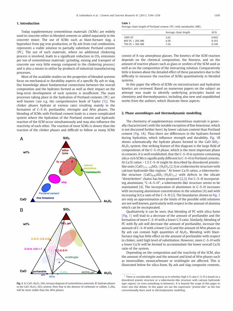
Table 1Average chain length of Portland cement (PC) with metakaolin (MK).
Average chain length Al/Si
100% PC 2.62 0.04380% PC+20% MK 4.38 0.10370% PC+30% MK 7.24 0.149
1245B. Lothenbach et al. / Cement and Concrete Research 41 (2011) 1244–1256
1. Introduction
Today supplementary cementitious materials (SCMs) are widelyused in concrete either in blended cements or added separately in theconcrete mixer. The use of SCMs such as blast-furnace slag, abyproduct from pig iron production, or fly ash from coal combustion,represents a viable solution to partially substitute Portland cement(PC). The use of such materials, where no additional clinkeringprocess is involved, leads to a significant reduction in CO2 emissionsper ton of cementitious materials (grinding, mixing and transport ofconcrete use very little energy compared to the clinkering process)and is also a means to utilize by-products of industrial manufacturingprocesses.
Most of the available studies on the properties of blended systemsfocus on mechanical or durability aspects of a specific fly ash or slag.Our knowledge about fundamental connections between the overallcomposition and the hydrates formed as well as their impact on thelong-term development of such systems is insufficient. The mainprocesses taking place in the hydration of Portland cements (PC) arewell known (see e.g. the comprehensive book of Taylor [1]). Theclinker phases hydrate at various rates resulting mainly in theformation of C–S–H, portlandite, ettringite and AFm phases. Theblending of SCMs with Portland cement leads to a more complicatedsystem where the hydration of the Portland cement and hydraulicreaction of the SCM occur simultaneously and may also influence thereactivity of each other. The reaction of most SCMs is slower than thereaction of the clinker phases and difficult to follow as many SCMs
Fig. 1. A) CaO–Al2O3–SiO2 ternary diagram of cementitious materials, B) hydrate phasesin the CaO–Al2O3–SiO2 system. Note that in the absence of carbonate or sulfate, C3AH6
will be more stable than the AFm phases.
consist of X-ray amorphous glasses. The kinetics of the SCM reactiondepends on the chemical composition, the fineness, and on theamount of reactive phases such as glass or zeolites of the SCM used aswell as on the composition of the interacting solution. Comparativelylittle is known about the detailed effect of these parameters due to thedifficulty to measure the reaction of SCMs quantitatively in blendedsystems.
In this paper the effects of SCMs on microstructure and hydrationkinetics are reviewed. Based on numerous papers on the subject anattempt was made to identify underlying principles based onchemistry and thermodynamics, including also new and unpublishedworks from the authors, which illustrate these aspects.
2. Phase assemblages and thermodynamic modelling
The chemistry of supplementary cementitious materials is gener-ally characterized (with the notable exception offine limestone,whichis not discussed further here) by lower calcium content than Portlandcement (Fig. 1A). Thus there are differences in the hydrates formedduring hydration, which influence strength and durability. Fig. 1Bshows schematically the hydrate phases formed in the CaO–SiO2–
Al2O3 system. One striking feature of this diagram is the large field ofcompositions of the C–S–H phase, which is the most important phasein cements. It is well established, that the C–S–H in systems containingsilica-rich SCMs is significantly different to C–S–H in Portland cements.At Ca/Si ratios N1.5 C–S–H might be described by disordered jennite-like units (CaO)1.5.–1.9SiO2·(H2O)x [2,3] or a tobermorite structurewithcalcium hydroxide-like regions.1 At lower Ca/Si ratios, a tobermorite-like structure (CaO)0.83SiO2·(H2O)1.5) with defects in the silicate“dreierketten” chains has been proposed [2,3]. For C–S–H incorporat-ing aluminium, “C–A–S–H”, a tobermorite-like structure seems to bemaintained [4]. The incorporation of aluminium in C–S–H increaseswith increasing aluminium concentration in the solution [4] and withincreasing Si/Ca ratio of the C–S–H [2]. The boundaries shown in Fig. 1are only an approximation as the limits of the possible solid solutionsare notwell known, particularlywith respect to the amount of aluminawhich can be incorporated.
Qualitatively it can be seen, that blending of PC with silica fume(Fig. 1) will lead to a decrease of the amount of portlandite and theformation of more C–S–Hwith a lower C/S ratio. Similarly, blending ofPC with fly ash will decrease the amount of portlandite, increase theamount of C–S–Hwith a lower Ca/Si and the amount of AFm phases asfly ash can contain high quantities of Al2O3. Blending with blast-furnace slag has little effect on the amount of portlandite with respectto clinker, until high level of substitution. However, more C–S–H witha lower Ca/Si will be formed to accommodate the lower overall Ca/Siratio of the system.
Depending on the composition and the reactivity of the SCM, alsothe amount of ettringite and the amount and kind of AFm phases suchas monosulfate, monocarbonate or strätlingite are affected. This isillustrated below for silica fume, fly ash and slag composite cements.
1 There is considerable controversy as to whether high C/S ratio C–S–H is based on adisordered jennite structure or a tobermorite-like structure with calcium hydroxidetype regions (or even something in between). It is beyond the scope of this paper toenter into this debate. In this paper we use the expression “jennite-like” as this hasconventionally been used in thermodynamic modeling.
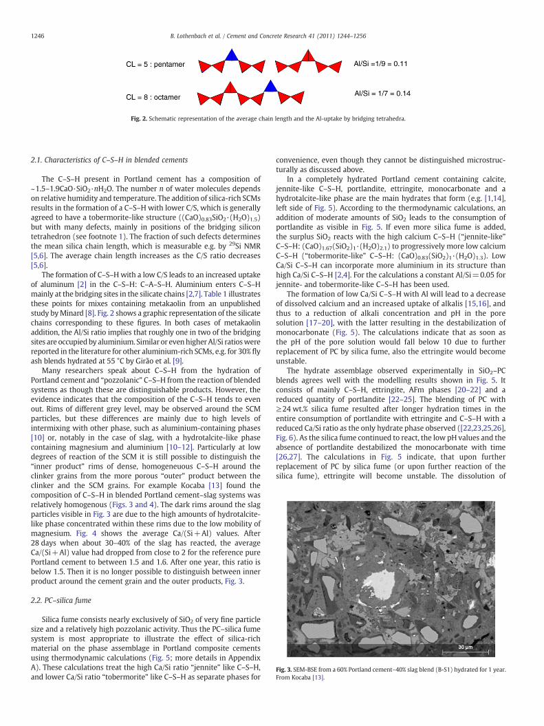
Fig. 2. Schematic representation of the average chain length and the Al-uptake by bridging tetrahedra.
Fig. 3. SEM-BSE from a 60% Portland cement–40% slag blend (B-S1) hydrated for 1 year.From Kocaba [13].
1246 B. Lothenbach et al. / Cement and Concrete Research 41 (2011) 1244–1256
2.1. Characteristics of C–S–H in blended cements
The C–S–H present in Portland cement has a composition of~1.5–1.9CaO·SiO2·nH2O. The number n of water molecules dependson relative humidity and temperature. The addition of silica-rich SCMsresults in the formation of a C–S–H with lower C/S, which is generallyagreed to have a tobermorite-like structure ((CaO)0.83SiO2·(H2O)1.5)but with many defects, mainly in positions of the bridging silicontetrahedron (see footnote 1). The fraction of such defects determinesthe mean silica chain length, which is measurable e.g. by 29Si NMR[5,6]. The average chain length increases as the C/S ratio decreases[5,6].
The formation of C–S–Hwith a low C/S leads to an increased uptakeof aluminum [2] in the C–S–H: C–A–S–H. Aluminium enters C–S–Hmainly at the bridging sites in the silicate chains [2,7]. Table 1 illustratesthese points for mixes containing metakaolin from an unpublishedstudy byMinard [8]. Fig. 2 shows a graphic representation of the silicatechains corresponding to these figures. In both cases of metakaolinaddition, the Al/Si ratio implies that roughly one in two of the bridgingsites are occupiedby aluminium. Similar or evenhigherAl/Si ratioswerereported in the literature for other aluminium-rich SCMs, e.g. for 30% flyash blends hydrated at 55 °C by Girão et al. [9].
Many researchers speak about C–S–H from the hydration ofPortland cement and “pozzolanic” C–S–H from the reaction of blendedsystems as though these are distinguishable products. However, theevidence indicates that the composition of the C–S–H tends to evenout. Rims of different grey level, may be observed around the SCMparticles, but these differences are mainly due to high levels ofintermixing with other phase, such as aluminium-containing phases[10] or, notably in the case of slag, with a hydrotalcite-like phasecontaining magnesium and aluminium [10–12]. Particularly at lowdegrees of reaction of the SCM it is still possible to distinguish the“inner product” rims of dense, homogeneuous C–S–H around theclinker grains from the more porous “outer” product between theclinker and the SCM grains. For example Kocaba [13] found thecomposition of C–S–H in blended Portland cement–slag systems wasrelatively homogenous (Figs. 3 and 4). The dark rims around the slagparticles visible in Fig. 3 are due to the high amounts of hydrotalcite-like phase concentrated within these rims due to the low mobility ofmagnesium. Fig. 4 shows the average Ca/(Si+Al) values. After28 days when about 30–40% of the slag has reacted, the averageCa/(Si+Al) value had dropped from close to 2 for the reference purePortland cement to between 1.5 and 1.6. After one year, this ratio isbelow 1.5. Then it is no longer possible to distinguish between innerproduct around the cement grain and the outer products, Fig. 3.
2.2. PC–silica fume
Silica fume consists nearly exclusively of SiO2 of very fine particlesize and a relatively high pozzolanic activity. Thus the PC–silica fumesystem is most appropriate to illustrate the effect of silica-richmaterial on the phase assemblage in Portland composite cementsusing thermodynamic calculations (Fig. 5; more details in AppendixA). These calculations treat the high Ca/Si ratio “jennite” like C–S–H,and lower Ca/Si ratio “tobermorite” like C–S–H as separate phases for
convenience, even though they cannot be distinguished microstruc-turally as discussed above.
In a completely hydrated Portland cement containing calcite,jennite-like C–S–H, portlandite, ettringite, monocarbonate and ahydrotalcite-like phase are the main hydrates that form (e.g. [1,14],left side of Fig. 5). According to the thermodynamic calculations, anaddition of moderate amounts of SiO2 leads to the consumption ofportlandite as visible in Fig. 5. If even more silica fume is added,the surplus SiO2 reacts with the high calcium C–S–H (“jennite-like”C–S–H: (CaO)1.67(SiO2)1·(H2O)2.1) to progressively more low calciumC–S–H (“tobermorite-like” C–S–H: (CaO)0.83(SiO2)1·(H2O)1.3). LowCa/Si C–S–H can incorporate more aluminium in its structure thanhigh Ca/Si C–S–H [2,4]. For the calculations a constant Al/Si=0.05 forjennite- and tobermorite-like C–S–H has been used.
The formation of low Ca/Si C–S–H with Al will lead to a decreaseof dissolved calcium and an increased uptake of alkalis [15,16], andthus to a reduction of alkali concentration and pH in the poresolution [17–20], with the latter resulting in the destabilization ofmonocarbonate (Fig. 5). The calculations indicate that as soon asthe pH of the pore solution would fall below 10 due to furtherreplacement of PC by silica fume, also the ettringite would becomeunstable.
The hydrate assemblage observed experimentally in SiO2–PCblends agrees well with the modelling results shown in Fig. 5. Itconsists of mainly C–S–H, ettringite, AFm phases [20–22] and areduced quantity of portlandite [22–25]. The blending of PC with≥24 wt.% silica fume resulted after longer hydration times in theentire consumption of portlandite with ettringite and C–S–H with areduced Ca/Si ratio as the only hydrate phase observed ([22,23,25,26],Fig. 6). As the silica fume continued to react, the low pH values and theabsence of portlandite destabilized the monocarbonate with time[26,27]. The calculations in Fig. 5 indicate, that upon furtherreplacement of PC by silica fume (or upon further reaction of thesilica fume), ettringite will become unstable. The dissolution of
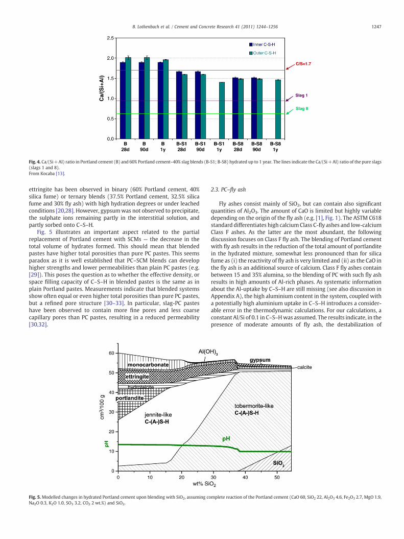
Fig. 4. Ca/(Si+Al) ratio in Portland cement (B) and 60% Portland cement–40% slag blends (B-S1; B-S8) hydrated up to 1 year. The lines indicate the Ca/(Si+Al) ratio of the pure slags(slags 1 and 8).From Kocaba [13].
1247B. Lothenbach et al. / Cement and Concrete Research 41 (2011) 1244–1256
ettringite has been observed in binary (60% Portland cement, 40%silica fume) or ternary blends (37.5% Portland cement, 32.5% silicafume and 30% fly ash) with high hydration degrees or under leachedconditions [20,28]. However, gypsumwas not observed to precipitate,the sulphate ions remaining partly in the interstitial solution, andpartly sorbed onto C–S–H.
Fig. 5 illustrates an important aspect related to the partialreplacement of Portland cement with SCMs — the decrease in thetotal volume of hydrates formed. This should mean that blendedpastes have higher total porosities than pure PC pastes. This seemsparadox as it is well established that PC–SCM blends can develophigher strengths and lower permeabilities than plain PC pastes (e.g.[29]). This poses the question as to whether the effective density, orspace filling capacity of C–S–H in blended pastes is the same as inplain Portland pastes. Measurements indicate that blended systemsshow often equal or even higher total porosities than pure PC pastes,but a refined pore structure [30–33]. In particular, slag-PC pasteshave been observed to contain more fine pores and less coarsecapillary pores than PC pastes, resulting in a reduced permeability[30,32].
Fig. 5.Modelled changes in hydrated Portland cement upon blending with SiO2, assuming coNa2O 0.3, K2O 1.0, SO3 3.2, CO2 2 wt.%) and SiO2.
2.3. PC–fly ash
Fly ashes consist mainly of SiO2, but can contain also significantquantities of Al2O3. The amount of CaO is limited but highly variabledepending on the origin of the fly ash (e.g. [1], Fig. 1). The ASTM C618standard differentiates high calciumClass C-fly ashes and low-calciumClass F ashes. As the latter are the most abundant, the followingdiscussion focuses on Class F fly ash. The blending of Portland cementwith fly ash results in the reduction of the total amount of portlanditein the hydrated mixture, somewhat less pronounced than for silicafume as (i) the reactivity of fly ash is very limited and (ii) as the CaO inthe fly ash is an additional source of calcium. Class F fly ashes containbetween 15 and 35% alumina, so the blending of PC with such fly ashresults in high amounts of Al-rich phases. As systematic informationabout the Al-uptake by C–S–H are still missing (see also discussion inAppendix A), the high aluminium content in the system, coupled witha potentially high aluminium uptake in C–S–H introduces a consider-able error in the thermodynamic calculations. For our calculations, aconstant Al/Si of 0.1 in C–S–Hwas assumed. The results indicate, in thepresence of moderate amounts of fly ash, the destabilization of
mplete reaction of the Portland cement (CaO 60, SiO2 22, Al2O3 4.6, Fe2O3 2.7, MgO 1.9,
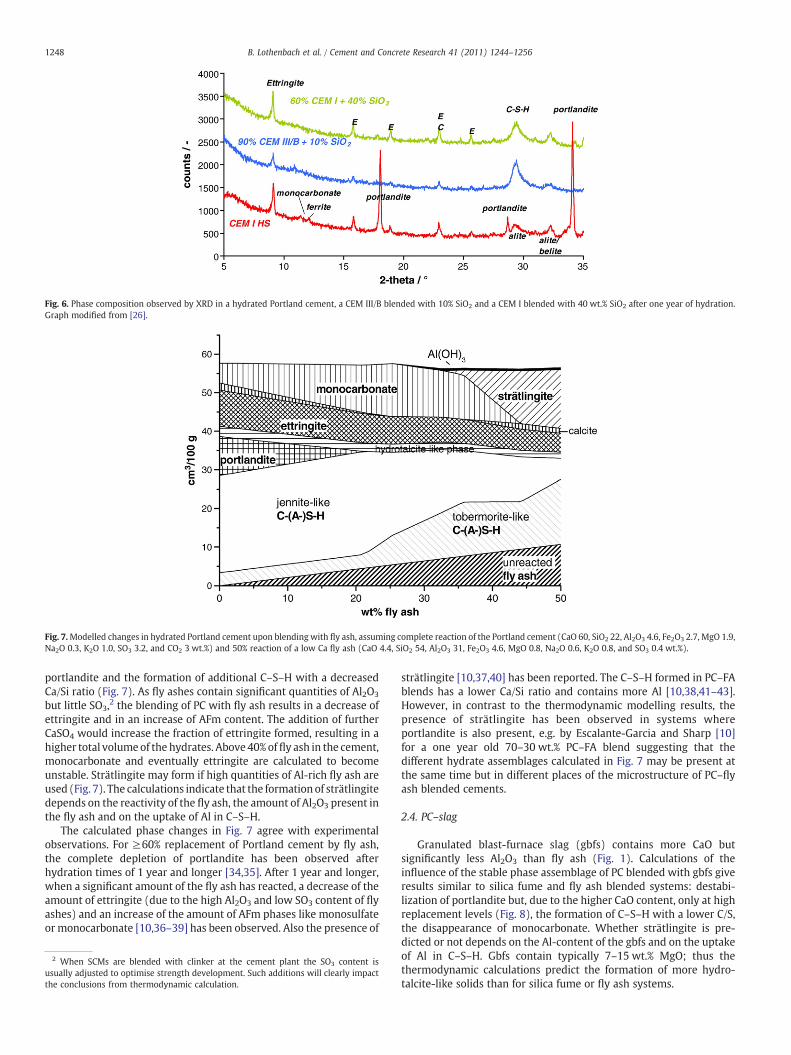
Fig. 6. Phase composition observed by XRD in a hydrated Portland cement, a CEM III/B blended with 10% SiO2 and a CEM I blended with 40 wt.% SiO2 after one year of hydration.Graph modified from [26].
Fig. 7.Modelled changes in hydrated Portland cement upon blending with fly ash, assuming complete reaction of the Portland cement (CaO 60, SiO2 22, Al2O3 4.6, Fe2O3 2.7, MgO 1.9,Na2O 0.3, K2O 1.0, SO3 3.2, and CO2 3 wt.%) and 50% reaction of a low Ca fly ash (CaO 4.4, SiO2 54, Al2O3 31, Fe2O3 4.6, MgO 0.8, Na2O 0.6, K2O 0.8, and SO3 0.4 wt.%).
1248 B. Lothenbach et al. / Cement and Concrete Research 41 (2011) 1244–1256
portlandite and the formation of additional C–S–H with a decreasedCa/Si ratio (Fig. 7). As fly ashes contain significant quantities of Al2O3
but little SO3,2 the blending of PC with fly ash results in a decrease ofettringite and in an increase of AFm content. The addition of furtherCaSO4 would increase the fraction of ettringite formed, resulting in ahigher total volumeof the hydrates. Above40% offly ash in the cement,monocarbonate and eventually ettringite are calculated to becomeunstable. Strätlingite may form if high quantities of Al-rich fly ash areused (Fig. 7). The calculations indicate that the formationof strätlingitedepends on the reactivity of the fly ash, the amount of Al2O3 present inthe fly ash and on the uptake of Al in C–S–H.
The calculated phase changes in Fig. 7 agree with experimentalobservations. For ≥60% replacement of Portland cement by fly ash,the complete depletion of portlandite has been observed afterhydration times of 1 year and longer [34,35]. After 1 year and longer,when a significant amount of the fly ash has reacted, a decrease of theamount of ettringite (due to the high Al2O3 and low SO3 content of flyashes) and an increase of the amount of AFm phases like monosulfateor monocarbonate [10,36–39] has been observed. Also the presence of
2 When SCMs are blended with clinker at the cement plant the SO3 content isusually adjusted to optimise strength development. Such additions will clearly impactthe conclusions from thermodynamic calculation.
strätlingite [10,37,40] has been reported. The C–S–H formed in PC–FAblends has a lower Ca/Si ratio and contains more Al [10,38,41–43].However, in contrast to the thermodynamic modelling results, thepresence of strätlingite has been observed in systems whereportlandite is also present, e.g. by Escalante-Garcia and Sharp [10]for a one year old 70–30 wt.% PC–FA blend suggesting that thedifferent hydrate assemblages calculated in Fig. 7 may be present atthe same time but in different places of the microstructure of PC–flyash blended cements.
2.4. PC–slag
Granulated blast-furnace slag (gbfs) contains more CaO butsignificantly less Al2O3 than fly ash (Fig. 1). Calculations of theinfluence of the stable phase assemblage of PC blended with gbfs giveresults similar to silica fume and fly ash blended systems: destabi-lization of portlandite but, due to the higher CaO content, only at highreplacement levels (Fig. 8), the formation of C–S–H with a lower C/S,the disappearance of monocarbonate. Whether strätlingite is pre-dicted or not depends on the Al-content of the gbfs and on the uptakeof Al in C–S–H. Gbfs contain typically 7–15 wt.% MgO; thus thethermodynamic calculations predict the formation of more hydro-talcite-like solids than for silica fume or fly ash systems.
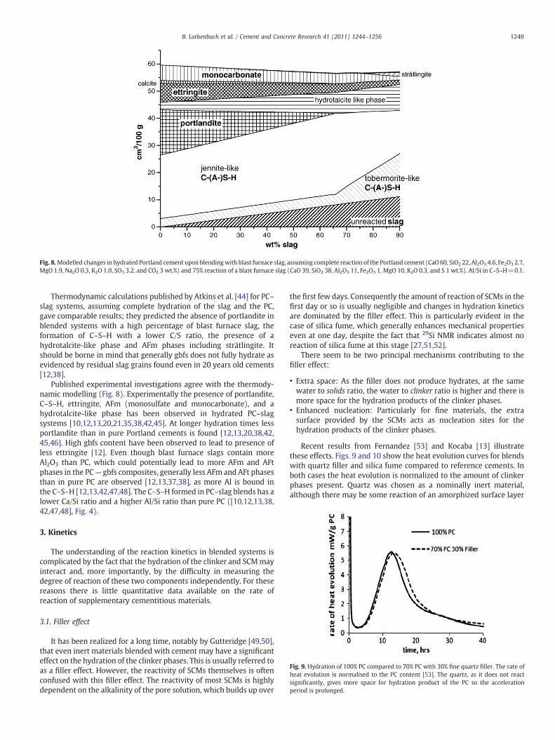
Fig. 8.Modelled changes in hydrated Portland cement upon blendingwith blast furnace slag, assuming complete reaction of the Portland cement (CaO 60, SiO2 22, Al2O3 4.6, Fe2O3 2.7,MgO 1.9, Na2O 0.3, K2O 1.0, SO3 3.2, and CO2 3 wt.%) and 75% reaction of a blast furnace slag (CaO 39, SiO2 38, Al2O3 11, Fe2O3 1, MgO 10, K2O 0.3, and S 1 wt.%). Al/Si in C–S–H=0.1.
Fig. 9. Hydration of 100% PC compared to 70% PC with 30% fine quartz filler. The rate ofheat evolution is normalised to the PC content [53]. The quartz, as it does not reactsignificantly, gives more space for hydration product of the PC so the accelerationperiod is prolonged.
1249B. Lothenbach et al. / Cement and Concrete Research 41 (2011) 1244–1256
Thermodynamic calculations published by Atkins et al. [44] for PC–slag systems, assuming complete hydration of the slag and the PC,gave comparable results; they predicted the absence of portlandite inblended systems with a high percentage of blast furnace slag, theformation of C–S–H with a lower C/S ratio, the presence of ahydrotalcite-like phase and AFm phases including strätlingite. Itshould be borne in mind that generally gbfs does not fully hydrate asevidenced by residual slag grains found even in 20 years old cements[12,38].
Published experimental investigations agree with the thermody-namic modelling (Fig. 8). Experimentally the presence of portlandite,C–S–H, ettringite, AFm (monosulfate and monocarbonate), and ahydrotalcite-like phase has been observed in hydrated PC–slagsystems [10,12,13,20,21,35,38,42,45]. At longer hydration times lessportlandite than in pure Portland cements is found [12,13,20,38,42,45,46]. High gbfs content have been observed to lead to presence ofless ettringite [12]. Even though blast furnace slags contain moreAl2O3 than PC, which could potentially lead to more AFm and AFtphases in the PC— gbfs composites, generally less AFm and AFt phasesthan in pure PC are observed [12,13,37,38], as more Al is bound inthe C–S–H [12,13,42,47,48]. The C–S–H formed in PC–slag blends has alower Ca/Si ratio and a higher Al/Si ratio than pure PC ([10,12,13,38,42,47,48], Fig. 4).
3. Kinetics
The understanding of the reaction kinetics in blended systems iscomplicated by the fact that the hydration of the clinker and SCMmayinteract and, more importantly, by the difficulty in measuring thedegree of reaction of these two components independently. For thesereasons there is little quantitative data available on the rate ofreaction of supplementary cementitious materials.
3.1. Filler effect
It has been realized for a long time, notably by Gutteridge [49,50],that even inert materials blended with cement may have a significanteffect on the hydration of the clinker phases. This is usually referred toas a filler effect. However, the reactivity of SCMs themselves is oftenconfused with this filler effect. The reactivity of most SCMs is highlydependent on the alkalinity of the pore solution, which builds up over
the first few days. Consequently the amount of reaction of SCMs in thefirst day or so is usually negligible and changes in hydration kineticsare dominated by the filler effect. This is particularly evident in thecase of silica fume, which generally enhances mechanical propertieseven at one day, despite the fact that 29Si NMR indicates almost noreaction of silica fume at this stage [27,51,52].
There seem to be two principal mechanisms contributing to thefiller effect:
• Extra space: As the filler does not produce hydrates, at the samewater to solids ratio, the water to clinker ratio is higher and there ismore space for the hydration products of the clinker phases.
• Enhanced nucleation: Particularly for fine materials, the extrasurface provided by the SCMs acts as nucleation sites for thehydration products of the clinker phases.
Recent results from Fernandez [53] and Kocaba [13] illustratethese effects. Figs. 9 and 10 show the heat evolution curves for blendswith quartz filler and silica fume compared to reference cements. Inboth cases the heat evolution is normalized to the amount of clinkerphases present. Quartz was chosen as a nominally inert material,although there may be some reaction of an amorphized surface layer
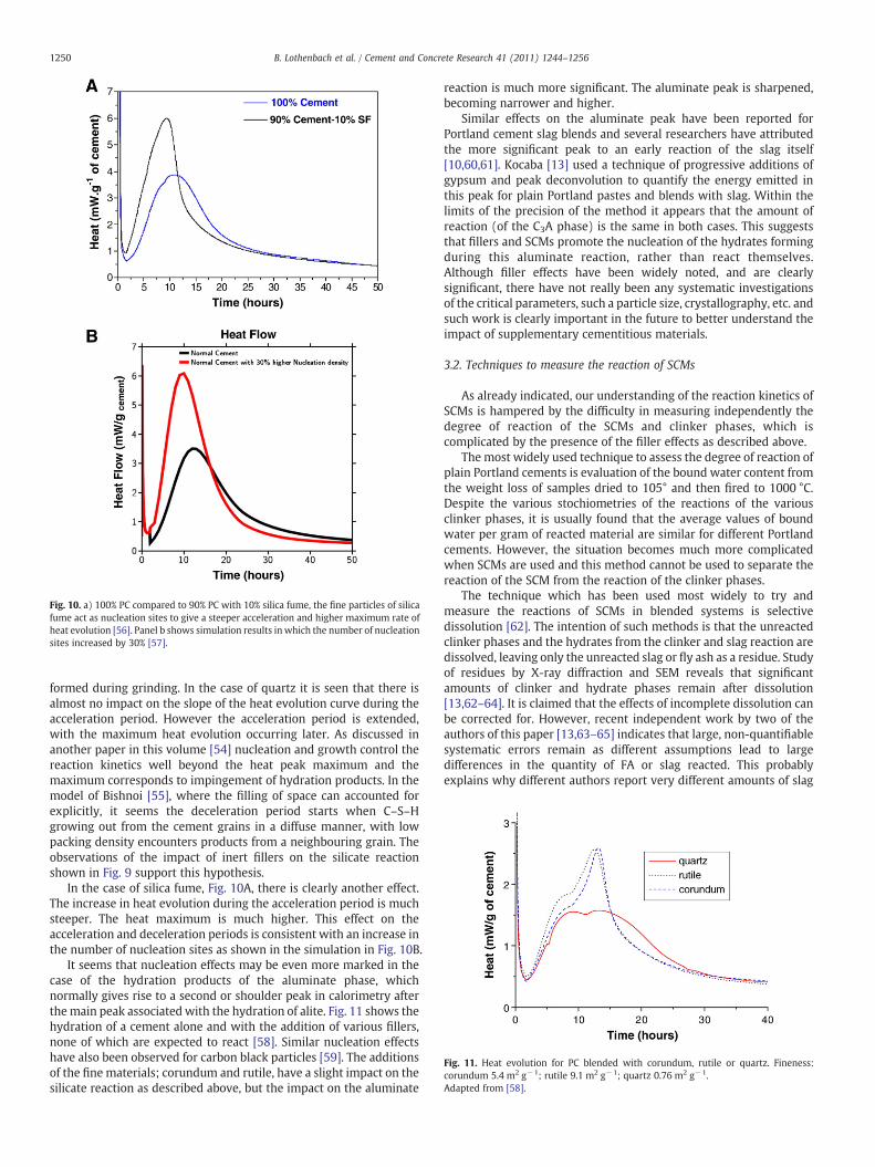
Fig. 10. a) 100% PC compared to 90% PC with 10% silica fume, the fine particles of silicafume act as nucleation sites to give a steeper acceleration and higher maximum rate ofheat evolution [56]. Panel b shows simulation results inwhich the number of nucleationsites increased by 30% [57].
Fig. 11. Heat evolution for PC blended with corundum, rutile or quartz. Fineness:corundum 5.4 m2 g−1; rutile 9.1 m2 g−1; quartz 0.76 m2 g−1.Adapted from [58].
1250 B. Lothenbach et al. / Cement and Concrete Research 41 (2011) 1244–1256
formed during grinding. In the case of quartz it is seen that there isalmost no impact on the slope of the heat evolution curve during theacceleration period. However the acceleration period is extended,with the maximum heat evolution occurring later. As discussed inanother paper in this volume [54] nucleation and growth control thereaction kinetics well beyond the heat peak maximum and themaximum corresponds to impingement of hydration products. In themodel of Bishnoi [55], where the filling of space can accounted forexplicitly, it seems the deceleration period starts when C–S–Hgrowing out from the cement grains in a diffuse manner, with lowpacking density encounters products from a neighbouring grain. Theobservations of the impact of inert fillers on the silicate reactionshown in Fig. 9 support this hypothesis.
In the case of silica fume, Fig. 10A, there is clearly another effect.The increase in heat evolution during the acceleration period is muchsteeper. The heat maximum is much higher. This effect on theacceleration and deceleration periods is consistent with an increase inthe number of nucleation sites as shown in the simulation in Fig. 10B.
It seems that nucleation effects may be even more marked in thecase of the hydration products of the aluminate phase, whichnormally gives rise to a second or shoulder peak in calorimetry afterthe main peak associated with the hydration of alite. Fig. 11 shows thehydration of a cement alone and with the addition of various fillers,none of which are expected to react [58]. Similar nucleation effectshave also been observed for carbon black particles [59]. The additionsof the fine materials; corundum and rutile, have a slight impact on thesilicate reaction as described above, but the impact on the aluminate
reaction is much more significant. The aluminate peak is sharpened,becoming narrower and higher.
Similar effects on the aluminate peak have been reported forPortland cement slag blends and several researchers have attributedthe more significant peak to an early reaction of the slag itself[10,60,61]. Kocaba [13] used a technique of progressive additions ofgypsum and peak deconvolution to quantify the energy emitted inthis peak for plain Portland pastes and blends with slag. Within thelimits of the precision of the method it appears that the amount ofreaction (of the C3A phase) is the same in both cases. This suggeststhat fillers and SCMs promote the nucleation of the hydrates formingduring this aluminate reaction, rather than react themselves.Although filler effects have been widely noted, and are clearlysignificant, there have not really been any systematic investigationsof the critical parameters, such a particle size, crystallography, etc. andsuch work is clearly important in the future to better understand theimpact of supplementary cementitious materials.
3.2. Techniques to measure the reaction of SCMs
As already indicated, our understanding of the reaction kinetics ofSCMs is hampered by the difficulty in measuring independently thedegree of reaction of the SCMs and clinker phases, which iscomplicated by the presence of the filler effects as described above.
The most widely used technique to assess the degree of reaction ofplain Portland cements is evaluation of the bound water content fromthe weight loss of samples dried to 105° and then fired to 1000 °C.Despite the various stochiometries of the reactions of the variousclinker phases, it is usually found that the average values of boundwater per gram of reacted material are similar for different Portlandcements. However, the situation becomes much more complicatedwhen SCMs are used and this method cannot be used to separate thereaction of the SCM from the reaction of the clinker phases.
The technique which has been used most widely to try andmeasure the reactions of SCMs in blended systems is selectivedissolution [62]. The intention of such methods is that the unreactedclinker phases and the hydrates from the clinker and slag reaction aredissolved, leaving only the unreacted slag or fly ash as a residue. Studyof residues by X-ray diffraction and SEM reveals that significantamounts of clinker and hydrate phases remain after dissolution[13,62–64]. It is claimed that the effects of incomplete dissolution canbe corrected for. However, recent independent work by two of theauthors of this paper [13,63–65] indicates that large, non-quantifiablesystematic errors remain as different assumptions lead to largedifferences in the quantity of FA or slag reacted. This probablyexplains why different authors report very different amounts of slag
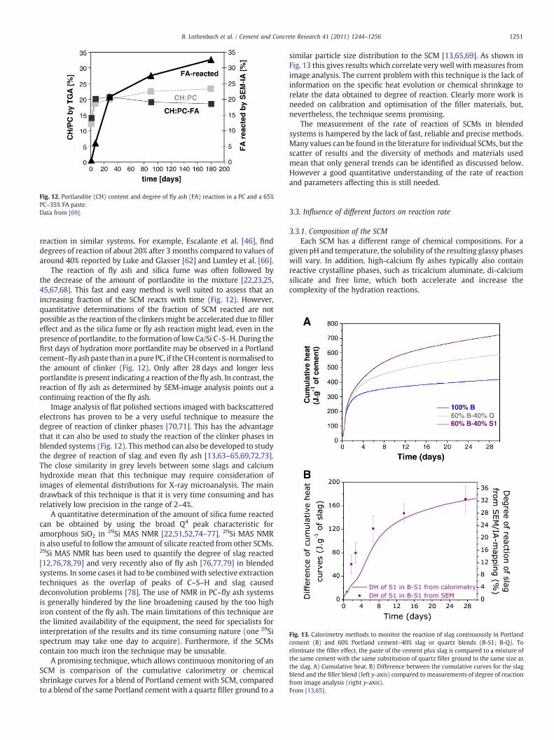
Fig. 12. Portlandite (CH) content and degree of fly ash (FA) reaction in a PC and a 65%PC–35% FA paste.Data from [69].
Fig. 13. Calorimetry methods to monitor the reaction of slag continuously in Portlandcement (B) and 60% Portland cement–40% slag or quartz blends (B-S1; B-Q). Toeliminate the filler effect, the paste of the cement plus slag is compared to a mixture ofthe same cement with the same substitution of quartz filler ground to the same size asthe slag. A) Cumulative heat. B) Difference between the cumulative curves for the slagblend and the filler blend (left y-axis) compared to measurements of degree of reactionfrom image analysis (right y-axis).From [13,65].
1251B. Lothenbach et al. / Cement and Concrete Research 41 (2011) 1244–1256
reaction in similar systems. For example, Escalante et al. [46], finddegrees of reaction of about 20% after 3 months compared to values ofaround 40% reported by Luke and Glasser [62] and Lumley et al. [66].
The reaction of fly ash and silica fume was often followed bythe decrease of the amount of portlandite in the mixture [22,23,25,45,67,68]. This fast and easy method is well suited to assess that anincreasing fraction of the SCM reacts with time (Fig. 12). However,quantitative determinations of the fraction of SCM reacted are notpossible as the reaction of the clinkers might be accelerated due to fillereffect and as the silica fume or fly ash reaction might lead, even in thepresence of portlandite, to the formation of lowCa/Si C–S–H. During thefirst days of hydration more portlandite may be observed in a Portlandcement–fly ashpaste than inapure PC, if theCHcontent is normalised tothe amount of clinker (Fig. 12). Only after 28 days and longer lessportlandite is present indicating a reaction of the fly ash. In contrast, thereaction of fly ash as determined by SEM-image analysis points out acontinuing reaction of the fly ash.
Image analysis of flat polished sections imaged with backscatteredelectrons has proven to be a very useful technique to measure thedegree of reaction of clinker phases [70,71]. This has the advantagethat it can also be used to study the reaction of the clinker phases inblended systems (Fig. 12). This method can also be developed to studythe degree of reaction of slag and even fly ash [13,63–65,69,72,73].The close similarity in grey levels between some slags and calciumhydroxide mean that this technique may require consideration ofimages of elemental distributions for X-ray microanalysis. The maindrawback of this technique is that it is very time consuming and hasrelatively low precision in the range of 2–4%.
A quantitative determination of the amount of silica fume reactedcan be obtained by using the broad Q4 peak characteristic foramorphous SiO2 in 29Si MAS NMR [22,51,52,74–77]. 29Si MAS NMRis also useful to follow the amount of silicate reacted from other SCMs.29Si MAS NMR has been used to quantify the degree of slag reacted[12,76,78,79] and very recently also of fly ash [76,77,79] in blendedsystems. In some cases it had to be combinedwith selective extractiontechniques as the overlap of peaks of C–S–H and slag causeddeconvolution problems [78]. The use of NMR in PC–fly ash systemsis generally hindered by the line broadening caused by the too highiron content of the fly ash. The main limitations of this technique arethe limited availability of the equipment, the need for specialists forinterpretation of the results and its time consuming nature (one 29Sispectrum may take one day to acquire). Furthermore, if the SCMscontain too much iron the technique may be unusable.
A promising technique, which allows continuous monitoring of anSCM is comparison of the cumulative calorimetry or chemicalshrinkage curves for a blend of Portland cement with SCM, comparedto a blend of the same Portland cement with a quartz filler ground to a
similar particle size distribution to the SCM [13,65,69]. As shown inFig. 13 this gives results which correlate very well withmeasures fromimage analysis. The current problem with this technique is the lack ofinformation on the specific heat evolution or chemical shrinkage torelate the data obtained to degree of reaction. Clearly more work isneeded on calibration and optimisation of the filler materials, but,nevertheless, the technique seems promising.
The measurement of the rate of reaction of SCMs in blendedsystems is hampered by the lack of fast, reliable and precise methods.Many values can be found in the literature for individual SCMs, but thescatter of results and the diversity of methods and materials usedmean that only general trends can be identified as discussed below.However a good quantitative understanding of the rate of reactionand parameters affecting this is still needed.
3.3. Influence of different factors on reaction rate
3.3.1. Composition of the SCMEach SCM has a different range of chemical compositions. For a
given pH and temperature, the solubility of the resulting glassy phaseswill vary. In addition, high-calcium fly ashes typically also containreactive crystalline phases, such as tricalcium aluminate, di-calciumsilicate and free lime, which both accelerate and increase thecomplexity of the hydration reactions.
1252 B. Lothenbach et al. / Cement and Concrete Research 41 (2011) 1244–1256
3.3.2. Replacement levelDue to different levels of reactivity of different types of SCMs, for
sufficient rates of reaction required to attain equivalent strengths,replacement levels are different. For example, 20% low-calcium flyash, 35% slag, 4% silica fume and 10%metakaolin might be expected toprovide similar 28-day strengths in concrete cured at 20 °C (e.g.[19,80]). While early-age strengths might be reduced, higher levels ofSCMmay be required to attain special performance, such as control ofalkali–silica reaction (ASR), increased chloride penetration resistance,sulfate resistance (e.g. N65% gbfs for high SR), or lower heat ofhydration (e.g. N50% slag or N30% fly ash). Due to extremely highsurface areas, silica fume and metakaolin will increase rates ofreaction, in part due to nucleation effects (silica fume) and in part dueto pozzolanic reaction. However, at excessive replacement rates,reaction rates are reduced due to reduced pH resulting from the rapidearly rates of reaction.
3.3.3. Solution pHThe solubility of amorphous silica is extremely sensitive to
increases in pH between 12 and 14. The higher the pH, the fasterthe rate of reaction [81,82]. In Portland cement–SCM blends, the highpH is provided by alkali hydroxides and calcium hydroxide, with poresolution pH increasing rapidly in the first few hours of hydration assulfate ions are removed from pore solution due to reaction withaluminates. To maintain electro-neutrality, hydroxyl ions replace thesulfate ions in solution, and pH levels are usually maintained between13 and 14 after about 24 h [83,84]. These hydroxyl ions allow thesecondary reactions to occur with the amorphous silica-rich phases inSCMs. Provided that sufficient hydroxyl ions remain in solution tomaintain the pH of the pore solution, the SCM reactions will continue.If the SCM replacement level is too high, the pHwill drop, reducing thesolubility of the amorphous silicates and thus slowing the rate ofreaction.
3.3.4. TemperatureBoth pozzolanic and the latent hydraulic slag reaction rates are
typically more sensitive to temperature [22,34,52,85], reacting moreslowly than Portland cements at temperatures below about 15 °C butrates are often accelerated at temperatures above 27 °C, usuallyassociated with hot-weather concreting. This temperature sensitivityoften limits practical cement replacement levels in cool weather, butallows higher replacement levels in warm weather.
3.4. PC–silica fume
The reactivity of silica fume (SF) is generally larger than the one ofslag or fly ash [45] due to its small particle size. However,measurements of the relative decrease of the amount of portlanditedue to the pozzolanic reaction and 29Si MAS NMR indicate a ratherslow reaction of the silica fume in blended systems continuing formonths [45,51,52,75,77]. 29Si NMR indicates relatively little reaction(~5%) of silica fume during the first hours in PC–SF mixtures, whileafterwards the reaction rate is strongly increased, so that 20 to 80% ofthe silica fume have reacted after 2 days or longer [27,51,77,86]. Asthe pH in the pore solution of PC pastes increases strongly afterapprox. 12 to 16 h (e.g. [83,84]), the reaction of the silica fume is thenaccelerated. At later ages, the additional C–S–H formed by the reactionof the silica fume takes up alkalis, decreasing the pH of the poresolution [67,87] so that the further reaction of the silica fume slowsdown. Similarly, high replacement of PC by silica fume decreases thereaction of silica fume [21,52] as the pH of the pore solution decreases.However, even in the absence of portlandite, silica fume continues toreact, but more slowly [22]. At higher temperatures the reaction of thesilica fume proceeds faster [22,52,85,88].
3.5. PC–fly ash
The reaction of fly ash is slow at ambient temperatures and onlyafter longer hydration times (≥1 week), the quantity of portlanditerelative to the amount of Portland cement is reduced [34,37,89–92]. Initially, the amount of portlandite compared to pure PC,increases slightly [34,45,89,90] (Fig. 12), as the hydration of theclinker is accelerated due to the filler effect thus producing moreportlandite. This slow reaction of the fly ash is the reason that thehydrate assemblage of Portland cement–fly ash blends is initiallyidentical to the pure Portland cement system: C–S–H, portlandite,ettringite, and AFm phases like monocarbonate or monosulfate[21,36,39]. High quantities of FA slow down the reaction [34,90],while higher temperatures [34] accelerate the reaction of fly ashconsiderably.
3.6. PC–slag
Generally, slags show a faster reaction than fly ashes. The fractionof slag reacted after a specific time increases if less slag is present inthe blend [12]. As for other SiO2-rich materials the reactivity of slagdecreases with decreasing pH and thus with less PC present in theblended system. During the first hours or days of hydration, however,the amount of portlandite (relative to Portland cement) is in blendedPC–slag systems similar or even higher than in pure Portland cements[13,45,46] due to faster reaction of the clinkers caused by the fillereffect. In the long term generally a small to moderate reduction of theamount of portlandite (relative to Portland cement) is observed[13,37,45,46].
4. Liquid phase
4.1. Changes in pore solution composition
The blending of Portland cement with silica fume lowers thealkali and hydroxide concentrations in the pore solution significant-ly [17,67,93]. Once portlandite is depleted, the calcium concentra-tion is also reduced. The same effect can also be observed forPortland systems blended with low-calcium fly ash [67,94–98]. Highcalcium fly-ash systems have been observed to exhibit pH values inthe range of 12–13, with relatively low alkali concentration buthigher alumina concentrations than Portland cement systems [40].However, some Class C fly ashes can have very high alkali contentsand thus increase the pH compared to PC [99]. The blending of PCwith SCM rich in silica and poor in alkalis, leads to a reduction of thepH and the alkali concentrations in the pore solutions as (i) thePortland cement is diluted, (ii) the portlandite is consumed by thepozzolanic reaction leading to lower Ca concentration in the poresolution and (iii) as C–S–H with a lower Ca/Si ratio and higheralumina content leads to an increase in alkali uptake by C–S–H[15,16]. The higher sorption of alkalis by low Ca/Si C–S–H is probablycaused by the negative charges due to the ionisation of silanolgroups, the partial substitution of Si(IV) by Al(III) and the lowerconcentrations of calcium. The increased uptake of alkalis by the lowCa/Si C–S–H leads to a reduction in pore solution alkalinity far inexcess of that resulting from simple dilution of the Portland cementalkalis [40,67,87,95,96].
In Portland cements blended with slags, an additional effect lowersthepHvalues of thepore solution.Not only thedilution of thePC and theincreased uptake of alkali by the low Ca/Si C–S–H, but also the highconcentrations of negatively charged soluble sulfur species lower thepH. The reducing conditions in blast furnace slags lead to the presenceofreduced sulfur species such as sulfide (HS−), sulfite (SO3
2−) andthiosulfate (S2O3
2−) in the pore solutions [93,95,100–102]. Highconcentrations of these negatively charged soluble sulfur specieslower the dissolved hydroxide concentrations and thus the pH in the
1253B. Lothenbach et al. / Cement and Concrete Research 41 (2011) 1244–1256
pore solution significantly as the electroneutrality of the solution has tobe maintained.
4.2. Long-term alkalinity
The reduction of the alkali concentration and the pH of the poresolution of blended cements is found to reduce alkali silica reaction(ASR) and the resulting expansion. Whether blending merely delaysASR or prevents it, depends on the long-termpore solution alkalinity. Inblends with silica fume, where no additional alumina is present in thepozzolan, the alkalis are reduced due to initial hydration reactions, buttheir concentrations slowly increase over time [67,87]. The reductions inalkalinity remain stable (i.e. alkalis are not released over time) whenalumina-bearing SCMs such as fly ash are used [67,87], possibly due tothe formation of alumina-substituted C–A–S–H. These differences inalkali concentration also lead to differences in long-term expansion, asconfirmed by the continuing expansion of silica fumeblended specimencontaining up to 10% of silica fume [18,103], while slag or fly ash blendsare more effective in reducing expansion also in the long term.
Fly ashes can have a wide variety of calcium and alkali contents,and this has been found to influence their ability to reduce alkalinityand to mitigate deleterious ASR expansions [18,98]. For fly ashes ofdifferent compositions, the alkalis released from the PC–SCM systemincrease as the calcium and alkali contents of the blends increased andtheir silica content decrease [99]. Ternary blends containing silicafume and fly ash also show superior performance in terms of bindingand retaining alkalis, even though silica fume on its own does notretain alkalis in the C–S–H over time.
5. Summary and perspectives
The presence of SCMs influences the amount and kind of hydratesformed in cementitious systems and thus the volume, the porosity andfinally the durability of such systems. At the levels of substitutionnormally used, the major change is in the composition of the C–S–Hphase which moves to lower Ca/Si ratios, despite the fact thatportlandite is still present in most systems. For SCMs containingalumina the C–S–H also incorporates a considerable amount of thiselement. In addition to the changes in C–S–H, the amounts of aluminate-containing hydrates may increase and when the SCM containmagnesium, a hydrotalcite-like phase may appear. In general thechanges in phase assemblagesmay bewell captured by thermodynamicmodelling, although better knowledge of the limits of solid solution ofC–S–H (particularly with regard to the uptake of aluminium) is needed.
As a consequence of the changes in phase assemblages, andparticularly the changes in C–S–H, the pore solutions in blended systemsdiffer from those in pure Portland materials. The main tendency is tolower levels of pH. This is very beneficial to avoid alkali silica reaction.
The effect of SCMs on reaction kinetics is complicated by theinteraction between the clinker phases and the SCMs. At early ages“filler” effects dominate, leading to increased, and sometimes alsofaster, reaction of the clinker phases, due more space relative to theamount of clinker and increased nucleation rates. The hydration of thealuminate phases, which occurs after the main silicate hydration peakis often more sensitive to nucleation effects.
The reactions of SCMs themselves are difficult to measure,although promising new methods are being developed. Because ofthis, we do not at present have a detailed quantitative understandingof the parameters affecting reaction rate. However general trends areclear: The reaction of SCMs (including silica fume) only starts after thefirst day or so, when the pH of the pore solution rises due toconsumption of sulfate and release of alkalis by reaction of the clinkerphases, however the lower Ca/Si ratio C–S–H may adsorb alkalis,contributing to a reduction in reaction rate over time. The particle sizeof the SCM is clearly important as the reaction takes place at thesurface, fine materials react faster. The composition of the glassy
materials also plays a role, but a good appreciation of this is lacking. Avery important parameter is also the temperature. Higher tempera-tures greatly accelerate the rate of reaction of SCM. However, again,although disparate information exists in the literature, we do notcurrently have a good quantitative understanding of the effects oftemperature.
It is clear that the effects of SCMs on reaction kinetics is a fieldwhere more systematic study is needed. The increasingly diverserange of supplementary materials used (and proposed for use) incementitious materials highlights the need for generic, quantitativerelations between composition, particle size and other characteristicson the one hand and exposure conditions such as temperature andrelative humidity on the other in order to predict the evolution ofphases assemblages and microstructure.
Acknowledgements
This paper is an outcome of the International Summit on CementHydration Kinetics and Modeling. The authors acknowledge financialsupport from Nanocem for the work of Vanessa Kocaba, from the SwissNational Science Foundation (snf) for the study of Rodrigo FernandezLopez and Aditya Kumar, from COIN (COncrete INnovation centre) forthe study of Klaartje De Weerdt and from Nagra (Swiss NationalCooperative for the Disposal of RadioactiveWaste) for the experimentalworkon lowalkali cements. The authorswould like to thankalsoGwennLe Saout, Luigi Brunetti, HelenMinard, Jorgen Skibsted andMohsen BenHaha for their support and helpful discussions.
Appendix A. Thermodynamic modelling
Thermodynamic modelling or also mass balance calculations canbe used to predict the stable phase assemblage based on thecomposition of the starting materials. Changes in the overall chemicalcomposition of the anhydrous system affect the amount as well as thekind of hydrates that will form. The simplest way to calculate thecomposition of a hydrated cement is to do mass balance calculationsbased on the chemical composition of the unhydrated cement[104,105]. These calculations have the advantage that they can becarried out simply with a calculator, but also the disadvantage that thepossible stable phase assemblage has to be known a priori. The use ofthermodynamic calculations allows the prediction of the hydratecomposition also in less well-known systems, easy and fast parametervariations and thus the systematic study of the effects of changesin the composition of the starting materials or in temperature[14,106,107].
A.1. Basics of thermodynamic modelling
The thermodynamic calculations in this paper were carried outusing the Gibbs free energyminimization program GEMS [108]. GEMSis a broad-purpose geochemical modelling code which computesequilibrium phase assemblage and speciation in a complex chemicalsystem from its total bulk elemental composition. Chemical interac-tions involving solids, solid solutions, and aqueous electrolyte areconsidered simultaneously. The speciation of the dissolved species aswell as the kind and amount of solids precipitated are calculated. Thethermodynamic data for aqueous species, gaseous phases as well asfor many solids were taken from the PSI-GEMS thermodynamicdatabase [109,110]. Solubility products for cement minerals includingettringite, different AFm phases, hydrogarnet, C–S–H and hydrotalcitewere taken from the cemdata07 compilation [106,111]. The formationof siliceous hydrogarnet has been excluded due to its slow kinetic offormation in all the calculations shown in this paper.
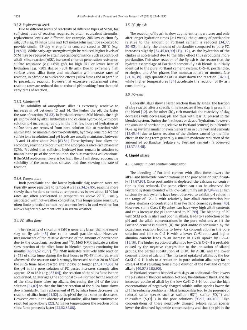
Fig. A1. Aqueous concentrations and mole fractions of the C–S–H solid solution end-members (jennite–tobermorite) as a function of the Ca/Si ratio. The presence of portlandite andamorphous SiO2 is indicated by horizontal lines (out of scale). Modified from [84,106].
1254 B. Lothenbach et al. / Cement and Concrete Research 41 (2011) 1244–1256
A.2. C–S–H
Due to its variable composition, C–S–H shows an incongruentsolubility behaviour upon decalcification. Dissolved calcium and siliconconcentrations varywith the calcium to silica ratio (C/S) of the solid andwith pH. A number of experimental investigations studied the solubilityof synthetic C–S–H and give a dataset to describe the solubility of C–S–Has a function of the Ca/Si ratio (see Fig. A1). In this paper, C–S–H phasesare modelled using the solid solution model originally developed byKulik andKersten [112,113] and later adaptedby Lothenbachet al. [106].The C–S–H system is described by an ideal solid solution with the end-members jennite (CaO)1.67(SiO2)1·(H2O)2.1 and tobermorite (CaO)0.83(SiO2)1·(H2O)1.3. The uptake of aluminiumby theC–S–H is simply takeninto account using measured Al/Si ratios in C–S–H, as thermodynamicmodels to calculate theAl-uptakebyC–S–Harenot available. Theuptakeof alkalis by C–S–H was approached by using an ideal solid solutionmodel between jennite-, tobermorite-like C–S–H, [(KOH)2.5SiO2H2O]0.2and [(NaOH)2.5SiO2H2O]0.2 as proposed by Kulik et al. [114].
A.3. Thermodynamic modelling of hydrated systems
To predict the stable phase assemblage in a hydrated system,assumptions on the degree of reaction of the anhydrous phases haveto be made, if possible based on measurements of the specific bindersor alternatively based on literature data. For the calculationspresented in this paper, where the influence of the presence ofdifferent quantities of SiO2 or fly ash on the hydrate assemblage ismodelled, a complete reaction of the Portland cement has beenassumed. This assumption was made as we are interested in the long-term composition and as more than 80% Portland cement clinker willhave reacted after 28 days or longer (e.g. [1]). For silica-rich SCMs,however, such an assumption is maybe not valid as they react much
slower so that even after very long hydration at ambient temperatureonly a fraction of the silica-rich material will have reacted (for adetailed discussion of the different factors affecting the kinetic ofreaction, see above). At higher temperature, however, a higher degreeof reaction of the silica-rich material will be achieved.
References
[1] H.F.W. Taylor, Cement Chemistry, Thomas Telford Publishing, London, 1997.[2] I.G. Richardson, G.W. Groves, The incorporation of minor and trace elements into
calcium silicate hydrates (C–S–H) gel in hardened cement pastes, Cement andConcrete Research 23 (1993) 131–138.
[3] H.F.W. Taylor, Nanostructure of C–S–H: current status, Advances in CementBased Materials 1 (1993) 38–46.
[4] X. Pardal, I. Pochard, A. Nonat, Experimental study of Si–Al substitution incalcium–silicate–hydrate (C–S–H) prepared under equilibrium conditions,Cement and Concrete Research 39 (2009) 637–643.
[5] J.J. Chen, J.J. Thomas, H.F.W. Taylor, H.M. Jennings, Solubility and structure ofcalcium silicate hydrate, Cement and Concrete Research 34 (2004) 1499–1519.
[6] X. Cong, R.J. Kirkpatrick, 29Si MAS NMR study of the structure of calcium silicatehydrate, Advances in Cement Based Materials 3 (1996) 144–156.
[7] P. Yu, R.J. Kirkpatrick, B. Poe, P.F. McMillan, X. Cong, Structure of calcium silicatehydrate (C–S–H): near-, mid-, and far-infrared spectroscopy, Journal of theAmerican Ceramic Society 82 (3) (1999) 742–748.
[8] H. Minard and J. Skibsted personal communication.[9] A.V. Girao, I.G. Richardson, R. Taylor, R.M.D. Brydson, Composition, morphology
and nanostructure of C–S–H in 70% white Portland cement–30% fly ash blendshydrated at 55 °C, Cement and Concrete Research 40 (2010) 1350–1359.
[10] J.I. Escalante-Garcia, J.H. Sharp, The chemical composition and microstructure ofhydration products in blended cements, Cement & Concrete Composites 26(2004) 967–976.
[11] I.G. Richardson, G.W. Groves, The structure of the calcium silicate phases presentin hardened pastes of white Portland cement/blast-furnace slag belnds, Journalof Materials Science 32 (18) (1997) 4793–4802.
[12] R. Taylor, I.G. Richardson, R.M.D. Brydson, Composition and microstructure of20-year-old ordinary Portland cement–ground granulated blast-furnace slagblends containing 0 to 100% slag, Cement and Concrete Research 40 (7) (2010)971–983.
1255B. Lothenbach et al. / Cement and Concrete Research 41 (2011) 1244–1256
[13] V. Kocaba (2009) Development and evaluation of methods to follow micro-structural development of cementitious systems including slags. Thesis EPFL No4523, Lausanne, Switzerland: 263 p pp.
[14] B. Lothenbach, G. Le Saout, E. Gallucci, K. Scrivener, Influence of limestone on thehydration of Portland cements, Cement and Concrete Research 38 (6) (2008)848–860.
[15] S.-Y. Hong, F.P. Glasser, Alkali binding in cement pastes. Part I. The C−S–H phase,Cement and Concrete Research 29 (1999) 1893–1903.
[16] S.-Y. Hong, F.P. Glasser, Alkali sorption by C–S–H and C–A–S–H gels. Part II. Roleof alumina, Cement and Concrete Research 32 (7) (2002) 1101–1111.
[17] J.A. Larbi, A.L.A. Fraay, J.M.J.M. Bijen, The chemistry of the pore fluid of silica fume-blended cement systems, Cement and Concrete Research 20 (1990) 506–516.
[18] J. Duchesne, M.A. Bérubé, The effectiveness of supplementary cementingmaterials in suppressing expansion due to ASR: another look at the reactionmechanisms. Part 2: pore solution chemistry, Cement and Concrete Research 24(2) (1994) 221–230.
[19] C. Cau-dit-Coumes, S. Courtois, D. Nectoux, S. Leclercq, X. Bourbon, Formulating alow-alkalinity, high resistance and low-heat concrete for radioactive wasterepositories, Cement and Concrete Research 36 (2006) 2152–2163.
[20] M. Codina, C. Cau-dit-Coumes, P. Le Bescop, J. Verdier, J.P. Ollivier, Design andcharacterization of low heat and low-alkalinity cements, Cement and ConcreteResearch 38 (2008) 437–448.
[21] E. Schäfer, Einfluss der Reaktion verschiedener Zementhauptbestandteile aufden Alkalihaushalt der Porenlösung des Zementsteins, Verlag Bau + TechnikGmbH, Düsseldorf, Germany, 2006, p. 179.
[22] G. Le Saout, E. Lécolier, A. Rivereau, H. Zanni, Chemical structure of cement agedat normal and elevated temperatures and pressures. Part II. Low permeabilityclass G oilwell cement, Cement and Concrete Research 36 (2006) 428–433.
[23] H. Cheng-yi, R.F. Feldman, Hydration reactions in Portland cement–silica fumeblends, Cement and Concrete Research 15 (1985) 585–592.
[24] H. Cheng-yi, R.F. Feldman, Influence of silica fume on the microstructuraldevelopment in cement mortars, Cement and Concrete Research 15 (1985)285–294.
[25] J.L. Garcia Calvo, A. Hidalgo, C. Alonso, L. Fernandez Luco, Development of low-pH cementitious materials for HLRW repositories. Resistance against groundwaters aggression, Cement and Concrete Research 40 (8) (2010) 1290–1297.
[26] B. Lothenbach, Thermodynamics and hydration of blended cement, 20108CONMOD 2010. Lausanne.
[27] B. Lothenbach, E. Wieland, D. Rentsch, R. Figi and B. Schwyn (in preparation)Hydration of blended cements. Cement and Concrete Research.
[28] T.T.H. Bach (2010) Evolution physico-chimique des liants bas pH hydrates.Influence de la temperature et mécanisme de retention des alcalins. ThesisUniversité de Bourgogne, Dijon, France: 236 pp.
[29] D.P. Bentz, O.M. Jensen, A.M. Coats, F.P. Glasser, Influence of silica fume ondiffusivity in cement-based materials I. Experimental and computer modelingstudies on cement pastes, Cement and Concrete Research 30 (6) (2000)953–962.
[30] X. Luo, D.D.L. Chung, Concrete–concrete pressure contacts under dynamicloading, studied by contact electrical resistance measurement, Cement andConcrete Research 30 (2) (2000) 323–326.
[31] S. Ouellet, B. Bussière, M. Aubertin, M. Benzaazoua, Microstructural evolution ofcemented paste backfill: mercury intrusion porosimetry test results, Cement andConcrete Research 37 (12) (2007) 1654–1665.
[32] R. Loser, B. Lothenbach, A. Leemann, M. Tuchscnmid, Chloride resistance ofconcrete and its binding capacity — comparison between experimental resultsand thermodynamic modeling, Cement and Concrete Composites 32 (1) (2010)34–42.
[33] K.O. Kjellsen, E.H. Atlassi, Pore structure of cement silica fume systems —
presence of hollow-shell pores, Cement and Concrete Research 29 (1) (1999)133–142.
[34] S. Hanehara, F. Tomosawa, M. Kobayakawa, K.R. Hwang, Effects of water/powderratio, mixing ratio of fly ash, and curing temperature on pozzolanic reaction of flyash in cement paste, Cement and Concrete Research 31 (1) (2001) 31-19.
[35] F.P. Glasser, M. Tyrer, K. Quillin, D. Ross, J. Pedersen, K. Goldthorpe, D.G.Bennett, M. Atkins, The chemistry of blended cements and backfills intendedfor use in radioactive waste disposal, UK Environment Agency TechnicalReport P98, 1998.
[36] T.D. Dyer, R.K. Dhir, Hydration reactions of cement combinations containingvitrified incinerator fly ash, Cement and Concrete Research 34 (2004) 849–856.
[37] K.A. Snyder, P.E. Stutzman, J. Philip, D. Esh, Hydrated phases in blendedcementitious systems for nuclear infrastructure, Longterm Performance ofCementitious Barriers and Reinforced Concrete in Nuclear Power Plants andWaste Management— NUCPERF 2009, RILEM, Cadarache, France, 2009, pp. 91–98.
[38] K. Luke, E. Lachowski, Internal composition of 20-year-old fly ash and slag-blended ordinary Portland cement pastes, Journal of the American CeramicSociety 91 (12) (2008) 4084–4092.
[39] G. Baert (2009) Physico-chemical interactions in Portland cement–(highvolume) fly ash binders. Thesis Department of Structural Engineering, Mangellaboratory for Concrete Research, Ghent University, pp.
[40] J.K. Tishmack, J. Olek, S. Diamond, S. Sahu, Characterization of pore solutionsexpressed from high-calcium fly-ash-water pastes, Fuel 80 (2001) 815–819.
[41] I.G. Richardson, The calcium silicate hydrates, Cement and Concrete Research 38(2) (2008) 137–158.
[42] A.M. Harrisson, N.B. Winter, H.F.W. Taylor, An examination of some andcomposite Portland cement pastes using scanning electron microscopy with X-ray capability, 8th ICCC, 1986, pp. 170–175.
[43] H.S. Pietersen (1993) Reactivity of fly ash and slag in cement. Thesis DelftUniversity of Technology, Delft, The Netherlands: 282 pp.
[44] M. Atkins, F.P. Glasser, A. Kindness, Phase relation and solubility modelling in theCaO–SiO2–Al2O3–MgO–SO3–H2O system: for application to blended cements,Material Research Society Symposium Proceedings 212 (1991) 387–394.
[45] I. Pane, W. Hansen, Investigation of blended cement hydration by isothermalcalorimetry and thermal analysis, Cement and Concrete Research 35 (2005)1155–1164.
[46] J.I. Escalante-Garcia, L.Y. Gomez, K.K. Johal, G. Mendoza, H. Mancha, J. Méndez,Reactivity of blast-furnace slag in Portland cement blends hydrated underdiffrent conditions, Cement and Concrete Research 31 (2001) 1403–1409.
[47] I.G. Richardson, G.W. Groves, The structure of the calcium silicate hydrate phasespresent in hardened pastes of white Portland cement blast-furnace slag blends,Journal of Materials Science 32 (18) (1997) 4793–4802.
[48] I.G. Richardson, The nature of C–S–H in hardened cements, Cement and ConcreteResearch 29 (8) (1999) 1131–1147.
[49] W.A. Gutteridge, J.A. Dalziel, Filler cement: the effect of the secondarycomponent on the hydration of Portland cement: part I. A fine non-hydraulicfiller, Cement and Concrete Research 20 (5) (1990) 778–782.
[50] W.A. Gutteridge, J.A. Dalziel, Filler cement: the effect of the secondarycomponent on the hydration of Portland cement: part 2: fine hydraulic binders,Cement and Concrete Research 20 (6) (1990) 853–861.
[51] J. Hjorth, J. Skibsted, H.J. Jakobsen, 29Si MAs NMR studies of Portland cementcomponents and effects of microsilica on the hydration reaction, Cement andConcrete Research 18 (1988) 789–798.
[52] H. Justness, in: P. Colombet, et al., (Eds.), Kinetics of reaction in cementitiouspastes containing silica fume as studied by 29Si MAS NMR, Nuclear MagneticResonance Spectroscopy of Cement-Based Materials, Springer, Berlin, 1998,pp. 245–267.
[53] R. Fernandez Lopez (2009) Calcined clayey soils as a potential replacemnt forcement in developing countries. Thesis EPFL No 4302, Lausanne, Switzerland:153 p pp.
[54] J.J. Thomas, J.J. Biernacki, J.W. Bullard, S. Bishnoi, J.S. Dolado, G.W. Scherer, A.Luttge, Modeling and simulation of cement hydration kinetics and microstruc-ture development, Cement and Concrete Research 411 (12) (2011) 1257–1278,(this issue).
[55] S. Bishnoi, K.L. Scrivener, Studying nucleation and growth kinetics of alitehydration using [mu]ic, Cement and Concrete Research 39 (10) (2009) 849–860.
[56] V. Kocaba private communication.[57] A. Kumar private communication.[58] G. Le Saout, K. Scrivener, Early hydration of Portland cement with corundum
addition, 16. Internationale Baustofftagung (ibausil). Weimar, Germany, 2006,pp. 409–416.
[59] R.J. Detwiler, P.K. Mehta, Chemical and physical effects of silica fume on themechanical properties of concrete, ACI Materials Journal 86 (6) (1989) 609–614.
[60] C.A. Utton, M. Hayes, J. Hill, N.B. Milestone, J.H. Sharp, Effect of temperatures upto 90 °C on the early hydration of Portland–blastfurnace slag cements, Journal ofthe American Ceramic Society 91 (3) (2008) 948–954.
[61] X. Wu, D.M. Roy, C.A. Langton, Early stage hydration of slag cement, Cement andConcrete Research 13 (2) (1983) 277–286.
[62] K. Luke, F.P. Glasser, Selectve dissolution of hydrated blast furnace slag cements,Cement and Concrete Research 17 (2) (1987) 273–282.
[63] M. Ben Haha, K. De Weerdt, B. Lothenbach, Quantification of the degree ofreaction of fly ash, Cement and Concrete Research 40 (11) (2010) 1620–1629.
[64] A. Gruskovnjak, B. Lothenbach, F. Winnefeld, B. Münch, S.C. Ko, M. Adler, U.Mäder, Quantification of hydration phases in super sulphated cements: reviewand new approaches, Advances in Cement Research 41 (3) (2010) 279–291.
[65] V. Kocaba, E. Gallucci and K. Scrivener (submitted for publication) Methods fordetermination of degree of reaction of slag in blended cement pastes. Cementand Concrete Research.
[66] J.S. Lumley, R.S. Gollop, G.K. Moir, H.F.W. Taylor, Degrees of reaction of the slag insome blends with Portland cement, Cement and Concrete Research 26 (1)(1996) 139–151.
[67] M.H. Shehata, M.D.A. Thomas, Use of ternary blends containing silica fume andfly ash to suppress expansion due to alkali–silica reaction in concrete, Cementand Concrete Research 32 (3) (2002) 341–349.
[68] S.K. Antiohos, V.G. Papadakis, E. Chaniotakis, S. Tsimas, Improving theperformance of ternary blended cements by mixing different types of flyashes, Cement and Concrete Research 37 (6) (2007) 877–885.
[69] K. De Weerdt, M. Ben Haha, G. Le Saout, K.O. Kjellsen, H. Justness, B. Lothenbach,Hydration mechanisms of ternary Portland cements containing limestonepowder and fly ash, Cement and Concrete Research 41 (3) (2010) 279–291.
[70] K. Scrivener, H.H. Patel, P.L. Pratt and L.J. Parrott (1987) Analysis of phases incement paste using backscattered electron images, methanol adsorption andthermogravimetric analysis. Microstructural Development during the Hydrationof Cement (Proc. Mat. Res. Soc. Symp., 85). Boston, USA: (Proc. Mat. Res. Soc.Symp., 85). 67–76.
[71] K. Scrivener, Backscattered electron imaging of cementitious microstructures:understanding and quantification, Cement and Concrete Composites 26 (2004)935–945.
[72] X. Feng, E.J. Garboczi, D.P. Bentz, P.E. Stutzman, T.O.Mason, Estimation of thedegreeof hydration of blended cement pastes by a scanning electron microscope point-counting procedure, Cement and Concrete Research 34 (10) (2004) 1787–1793.
[73] A. Brough, A. Atkinson, Sodium silicate-based, alkali-activated slag mortars partI. Strength, hydration and microstructure, Cement and Concrete Research 32 (6)(2002) 865–879.
1256 B. Lothenbach et al. / Cement and Concrete Research 41 (2011) 1244–1256
[74] C. Porteneuve, J.P. Korb, D. Petit, H. Zanni, Structure–texture correlation in ultra-high-performance concrete — a nuclear magnetic resonance study, Cement andConcrete Research 32 (1) (2002) 97–101.
[75] H.S. Pietersen, A.P.M. Kentgens, G.H. Nachtegaal, W.S. Veeman, J.M.J.M. Bijen, Wet-shotcrete for refractory castables, Proc. 4th International Conference on Fly Ash,Silica Fume, Slag and Natural Pozzolans in Concrete, 1992, pp. 795–812, Istanbul,Turkey: CANET/ACI SP-132-47.
[76] S.L. Poulsen (2009) Methodologies for measuring the degree of reaction inPortland cement blends with supplementary cementitious materials by 29Si and27Al MAS NMR spectroscopy. Thesis Department of Chemistry and Interdisci-plinary Nanoscience Center, Aarhus University, Aarhus, Denmark: 209 pp.
[77] S.L. Poulsen, H.J. Jakobsen, J. Skibsted, Methodologies for measuring the degree ofreaction in Portland cement blends with supplementary cementitious materialsby 27Al and 29Si MAS NMR spectroscopy, 17. Internationale Baustofftagung(ibausil). Weimar, Germany, 2009, pp. 177–188.
[78] H.M. Dyson, I.G. Richardson, A. Brough, A combined 29Si NMR and selectivedissolution technique for the quantitative evaluation of hydrated blast furnaceslag cement blends, Journal of the American Ceramic Society 90 (2007) 598.
[79] F. Brunet, T. Charpentier, C.N. Chao, H. Peycelon, A. Nonat, Characterization bysolid-state NMR and selective dissolution techniques of anhydrous and hydratedCEM V cement pastes, Cement and Concrete Research 40 (2) (2010) 208–219.
[80] B.B. Sabir, S. Wild, J. Bai, Metakaolin and calcined clays as pozzolans for concrete:a review, Cement & Concrete Composites 23 (2001) 441–454.
[81] B.R. Bickmore, K.L. Nagy, A.K. Gray, A.R. Brinkerhoff, The effect of Al(OH)4− on thedissoltion rate of quartz, Geochimica et Cosmochimica Acta 70 (2006) 290–305.
[82] P.M. Dove, The dissolution kintics of quartz in sodiumchloride solutions at 25° to300 °C, American Journal of Science 294 (1994) 665–712.
[83] R.S. Barneyback, S. Diamond, Expression and analysis of pore fluids of hardenedcement pastes and mortars, Cement and Concrete Research 11 (1981) 279–285.
[84] B. Lothenbach, F. Winnefeld, Thermodynamic modelling of the hydration ofPortland cement, Cement and Concrete Research 36 (2) (2006) 209–226.
[85] L.Y. Gómez-Zamorano, J.-I. Escalante-García, Effect of curing temperature on thenonevaporable water in Portland cement blended with geothermal silica waste,Cement & Concrete Composites 32 (2010) 603–610.
[86] J. Skibsted, O.M. Jensen, H.J. Jakobsen, Hydration kinetics for the alite, belite, andcalcium aluminate phase in Portland cements from 27Al and 29Si MAS NMRspectroscopy, 10th International congress on the chemistry of cement, , 1997,p. 2ii0568, Göteborg: Amarkai AB and Congrex Göteborg AG.
[87] J. Duchesne, M.A. Bérubé, Evaluation of the validity of the pore solutionexpression method from hardened cement pastes and mortars, Cement andConcrete Research 24 (3) (1994) 456–462.
[88] A. Leemann, G. Le Saout, F. Winnefeld, D. Rentsch, B. Lothenbach, Alkali–silicareaction — the influence of calcium on silica dissolution and the formation ofreaction products, Journal of the American Ceramic Society 94 (4) (2011)1243–1249.
[89] L. Lam, Y.L. Wong, C.S. Poon, Degree of hydration and gel/space ratio of highvolume fly ash/cement systems, Cement and Concrete Research 30 (2000)747–756.
[90] E. Sakai, S. Miyahara, S. Ohsawa, S.-H. Lee, M. Daimon, Hydration of fly ashcement, Cement and Concrete Research 35 (2005) 1135–1140.
[91] V.G. Papadakis, Effect of fly ash on Portland cement systems. Part I: low-calciumfly ash, Cement and Concrete Research 29 (1999) 1727–1736.
[92] V.G. Papadakis, Effect of fly ash on Portland cement systems. Part II: high-calciumfly ash, Cement and Concrete Research 30 (2000) 1647–1654.
[93] Rasheeduzzafar, E.S. Hussain, Effect of microsilica and blast furnace slag on poresolution composition and alkali–silica reaction, Cement & Concrete Composites13 (1991) 219–225.
[94] S. Diamond, Effects of two danish flyashes on alkali contents or pore solutions ofcement–flyash pastes, Cement and Concrete Research 11 (1981) 383–394.
[95] F.P. Glasser, K. Luke, M.J. Angus, Modification of cement pore fluid compositionsby pozzolanic additives, Cement and Concrete Research 18 (2) (1988) 165–178.
[96] P. Lorenzo, S. Goñi, S. Hernandez, A. Guerrero, Effect of fly ashes with high alkalicontent on the alkalinity of the pore solution of hydrated Portland cement paste,Journal of the American Ceramic Society 79 (2) (1996) 470–474.
[97] S. Goñi, M.P. Lorenzo, A. Guerrero, M.S. Hernández, Calcium hydroxidesaturation factors in the pore solution of hydrated Portland cement fly ashpastes, Journal of the American Ceramic Society 79 (4) (1996) 1041–1046.
[98] M.H. Shehata, M.D.A. Thomas, R.F. Bleszynski, The effects of fly ash compositionon the chemistry of pore solution in hydrated cement pastes, Cement andConcrete Research 29 (12) (1999) 1915–1920.
[99] M.H. Shehata, M.D.A. Thomas, Alkali release characteristics of blended cements,Cement and Concrete Research 36 (2006) 1166–1175.
[100] P. Longuet, L. Burglen, A. Zelwer, La phase liquide du ciment hydraté, Revue desmatériaux de construction 676 (1973) 35–41.
[101] C. Vernet, E. Démoulian, P. Gourdin, F. Hawthorn, Kinetics of slag cementshydration, 7th International Congress on the Chemistry of Cement, III, 1980,pp. 128–133.
[102] C. Vernet, Comportement de l'ion S– au cours de l'hydratation des ciments richeen laitier (CLK), Silicates industriels 47 (1982) 85–89.
[103] R.F. Bleszynski, R.D. Hooton, M.D.A. Thomas, C.A. Rogers, Durability of ternaryblend concretes with silica fume and blastfurnace slag: laboratory and outdoorexposure site studies, ACI Materials Journal 99 (5) (2002) 499–508.
[104] I. Juel, D. Herfort, R. Gollop, J. Konnerup-Madsen, H.J. Jakobsen, J. Skibsted, Athermodynamic model for predicting the stability of thaumasite, Cement &Concrete Composites 25 (2003) 867–872.
[105] E.P. Nielsen, D. Herfort, M.R. Geiker, Phase equilibria of hydrated Portlandcement, Cement and Concrete Research 35 (2005) 109–115.
[106] B. Lothenbach, T. Matschei, G. Möschner, F.P. Glasser, Thermodynamic modellingof the effect of temperature on the hydration and porosity of Portland cement,Cement and Concrete Research 38 (1) (2008) 1–18.
[107] T. Matschei, B. Lothenbach, F.P. Glasser, The role of calcium carbonate in cementhydration, Cement and Concrete Research 37 (4) (2007) 551–558.
[108] D. Kulik, GEMS-PSI 2.38 available at http://www.gems.web.psi.ch/ 20098 PSI-Villigen, Switzerland.
[109] W. Hummel, U. Berner, E. Curti, F.J. Pearson and T. Thoenen, Nagra/PSI ChemicalThermodynamic Data Base 01/01. 2002, USA, also published as Nagra TechnicalReport NTB 02-16, Wettingen, Switzerland: Universal Publishers/uPUBLISH.com.565.
[110] T. Thoenen, D. Kulik, Nagra/PSI chemical thermodynamic database 01/01 for theGEM-Selektor (V.2-PSI) geochemical modeling code, 20038 PSI TM-44-02-09.
[111] T. Matschei, B. Lothenbach, F.P. Glasser, Thermodynamic properties of Portlandcement hydrates in the system CaO–Al2O3–SiO2–CaSO4–CaCO3–H2O, Cementand Concrete Research 37 (10) (2007) 1379–1410.
[112] D.A. Kulik, M. Kersten, Aqueous solubility diagrams for cementitious wastestabilization systems: 4. A carbonation model for Zn-doped calcium-silicatehydrate by Gibbs energy minimization, Environmental Science & Technology 36(2002) 2926–2931.
[113] D.A. Kulik, M. Kersten, Aqueous solubility diagrams for cementitious wastestabilization systems: II, end-member stoichiometries of ideal calcium silicateshydrate solid solutions, Journal of the American Ceramic Society 84 (12) (2001)3017–3026.
[114] D. Kulik, J. Tits, E. Wieland, Aqueous–solid solution model of strontium uptake inC–S–H phases, Geochimica et Cosmochimica Acta 71 (12, Supplement 1) (2007)A530.