Graphical Input Peripheral
35
Graphical Input Peripheral Final Project Report 9 December 2016 E155 Charlotte Robinson and Alex Ozdemir Abstract Graphs are useful mathematical constructs which can be used to describe relationships. They’ve been used to model friendship networks, city streets, and more. However, while graphs are often very visual objects, the way we input them into computers is not very visual. We created a system which allows a computer to read the structure of a graph that a human has physically constructed using our peripheral device. The system begins a physical board with nodes (screws) and edges (wires) that the use can connect. An FPGA reads and writes to this board with the help of an ADC and a few analog multiplexers, ultimately determining the structure of the graph. The FPGA then sends this information to a Raspberry Pi, which displays the constructed graph.
Transcript of Graphical Input Peripheral

Graphical Input Peripheral Final Project Report
9 December 2016
E155
Charlotte Robinson and Alex Ozdemir
Abstract Graphs are useful mathematical constructs which can be used to describe relationships. They’ve been used to model friendship networks, city streets, and more. However, while graphs are often very visual objects, the way we input them into computers is not very visual. We created a system which allows a computer to read the structure of a graph that a human has physically constructed using our peripheral device. The system begins a physical board with nodes (screws) and edges (wires) that the use can connect. An FPGA reads and writes to this board with the help of an ADC and a few analog multiplexers, ultimately determining the structure of the graph. The FPGA then sends this information to a Raspberry Pi, which displays the constructed graph.

Introduction
In graph theory a graph is defined a set of nodes connected by edges which define relationships between different nodes, as can be observed in the left hand picture of Figure 1. Graphs like these can be used as powerful modeling tools for a variety of situations. For example Facebook can be modeled as a graph where people are nodes and friendships are edges, or the US highway system can be modeled as graph where cities are nodes and roads are edges, allowing mathematicians and computer science to view efficient travel as a graph algorithms problem. The applicability graphs in such a wide variety of applications means that there is a need for good ways to describe graphs and input them into computers. Right now a graph is put into a computer using an adjacency matrix like the one seen in the right panel of Figure 1, or by explicitly enumerating each edge. Although these textual descriptions of a graph make sense to computers that are far less intuitive for humans. In our project we aim to address this difficulty by creating a graph input peripheral that allows a person to input a graph into a computer in a way that is intuitive for a human.

The graphical input system is uses three main subsystems, as can be seen in the block diagram in Figure 2: the graphical input device itself, the FPGA which reads from and writes to the graph input device and uses this information to create an adjacency matrix, and the Raspberry Pi, which displays the adjacency matrix as a graph and can calculate and display the shortest distance between two nodes inputted by the user. The graph and an A/D converter are connected using an analog circuit. The A/D converter sends voltage information to the FPGA via SPI. The FPGA is connected to the PI also via SPI. The SPI displays the graph through a HDMI connection to a monitor. Each of these subsystems, as well as the analog circuit will be described in further detail in the following sections.
New Hardware: A Graph Input Peripheral The graph input peripheral is a hybrid mechanical and electronic device. From the perspective of the user, the board is mechanical: It consists of 19 nodes

(represented by long screws) arranged as an isometric lattice, which can be
connected to each other via physical edges with clips on either end. That is, the user see something like what is shown in Figure 3. However, the graphical in peripheral is also a electronic device. The nodes are not just screws - they are electric terminals that can have voltages written to them and read from them. Furthermore, they are connect via pulldown resistors to ground. The edges are not just physical edges, they are electrical connections with some known resistance. The scanning circuit on the FPGA interacts with the graphical input peripheral as an electronic system in order to infer which connections exist. To detect whether some v is connected to some u, the FPGA writes high to v, floats u, and write low to the rest of the nodes. There are two cases: either v and u are directly connected, or they are not. Both cases are shown in Figure 4.

First we consider the case on the left: when the two nodes are indeed connected. Given that the “edge” resistors and the pulldown resistors have the same resistance, the voltage V’ of the blue node is given by where n+2 is the numberV
n+2 other nodes V’ is connected to. In the case that the two nodes, are not connect, the voltage at V’ is clearly 0. Thus, by using a tree of analog multiplexers to connect an Analog to Digital Converter (ADC) to the blue node, we can distinguish V/(n+2) from 0, and thus determine whether the edge exists or not. Since we only have 19 nodes, the maximum value of n is 18, and we need only distinguish V/20 from zero, which we do by setting the threshold voltage to be V/32.
Schematics The graph input peripheral is connected to the FPGA via an analog circuit. As can be seen in the Appendix 4 this analog circuit works by tying together the write nodes from the FPGA, which will be writing 3.3 V, ground or z to the node, to the wires which will be being read from. This means that the read wire will be reading the voltage that each node. These nodes are also connected to ground through 2.7 kOhm pull down resistors, which prevent an unconnected node from shorting to

the FPGA when high is being written to it. The resistance of the pulldown resistor is the same as that of the resistive edge wires. We selected this since we calculated that having the same resistance for our edges and pull down resistors did not affect our ability to detect edges and allowed us to keep are resistors as small as possible, which minimized the the time constant of our circuit without burning out the FPGA. There are twenty nodes in total, each are connected to one write node of the FPGA. The twenty read wires were connected to the FPGA through an 8-channel multiplexer tree made up of three multiplexers and an ADC. The first eight nodes, nodes 0-7, are connected to a bottom level multiplexer whose output goes to channel four of the top-level multiplexer, and the next eight, nodes 8-15, went to a second bottom multiplexer whose output is connected to channel five of the top level multiplexer. The last four nodes, node 16-19, went directly into channels 0-3 of the top level multiplexer, whose output went to a A/D converter on the FPGA. Which node was read into the into then A/D converter is controlled by six wires coming from the FPGA, three of which controlled the output of the top level multiplexer, and three of which control the output of the two bottom level multiplexers. The values of the wires are determined by the FPGA.
FPGA Design In the graph input device system the FPGA’s main job is to write values to the nodes of the graph input device and then take in the resulting voltage values from the A/D converter, use this information to determine connectivity and then send an adjacency matrix, showing accurate connectivity, to the Pi. The inputs and outputs of the main system can be seen in Table 1.
Scanner The modules that controls the operation of the graph input device is the scanner module. The scanner, the modules inside of it and the modules connected to it can be seen in Appendix 5. This scanner calls a the ADC SPI, adc_spi, to request data and passes this information to a higher level module, to be placed in memory at an address also specified by scanner. It also sets the values of mux_con and w_node. Which address in memory that the data should populate and what values are assigned to mux_con and w_node are determined by the module triple_counter, which is called from scanner. Triple scanner also determines when values are written to memory and when information from the ADC is requested.

Triple_counter controls three clocks. The first is a fast clock which updates at every clock cycle and acts a delay, to guarantee that the value of the z node of the graph is not read until we are confident that all the electrical signals have fully propagated through the circuit. To do this the adc_read enable is connected to this clock and does not go high until the fast counter has achieved some value, which we set conservatively at 40,000. Fast counter is reset when the adc_read done goes high signaling the the voltage value of the node of interest has successfully reached the FPGA and the connectivity determination is about to be written to memory. This guarantees that the voltages being written the nodes of the graph input device do not change until the ADC is finished The second clock is is updated when fast counter is reset and represents the node which z will be written to and which will be written to. This is no is modules with number of nodes, so it will not exceed this value. When medium counter is equal to the total number of nodes slow, meaning that every nodes has been read, slow counter is updated. This counter represent the node which high will be written and also will not exceed the total number of nodes in the device. When slow counter has reached the total number of nodes, all the connections in the graph will have been read. Assuming that fast counter is approximately 40,000 clock cycles long and the graph as twenty nodes we find that to read the entire graph we must write high to 20 nodes, for each of these z must be written to 20 nodes, and each of the combinations of z and high will be maintained for approximately 40,000 clock cycles, so to read in the entire input periphery takes (20)*(20)*(40,000) = 16*10^6 clock cycles, and since the FPGA runs a 40 MHz clock, this is about (16*10^6)/(40*10^6) = 0.4 sec. Which is a relatively long time, however since the scanner runs constantly, updating memory with correct values, but the user interface only updates when requested by the user this delay is likely to go unnoticed. Additionally, if necessary, this delay can likely be reduced by decreasing the amount of wait cycles before the ADC is read, since we found, using an oscilloscope, that the time constants for out circuit are on the order of milliseconds, well below the time allowed by the 40,000 clock cycles delay.
SPI After values have been written to memory they can be read from memory whenever requested, by the Pi SPI. the verilog code governing the SPI is relatively simple since the FPGA is the slave to the PI, however some modification where necessary to make the SPI work effectively with memory. Most notably, when the Pi SPI is updating it locks write access the the memory, so that memory values can not be being changed by the scanner and read simultaneously.

Input Description Bit width
Output Description Bit Width
adc_miso
Master in slave out, coming from the ADC
8 bits w_node 20 bits each writing ground, 3.3 V or z to a node on the input device
20 bits
pi_cs chip select coming from the Pi
1 bit mux_con
Bits that control which nodes voltage is being read by the ADC.
6 bits
pi_sclk Sclk coming from the Pi
1 bit adc_cs chip select going to the ADC
1 bit
pi_mosi
Master out slave in coming from the Pi
8 bits adc_mosi
Master Out Slave In going to the ADC
8 bits
adc_sclk
Sclk coming from the ADC
1 bit
pi_miso Master in slave out going to the PI
8 bits
Table 1: FPGA I/O
Microcontrollers Design The microcontroller (Pi) runs two programs: one responsible for communication with the FPGA, and the other responsible for controlling the Graphical User Interface (GUI).
Communication between the Pi and FPGA The program which interacts with the FPGA is written in C and uses memory mapping to control the SPI0 peripheral which is wired to the FPGA. The FPGA implements SPI and satisfies the following communication convention:
1. Both master and slave write on the falling edge and read on the rising edge.

2. CS idles high, and communication must occur which CS is low. 3. When CS is low, if the FPGA receives a 1, it will begin sending a 20x20 bit
adjacency matrix during the next cycle of the SPI clock. As the matrix contains 400 bits, this will take 400 cycles.
a. The matrix elements are enumerated in row-major order. b. If a another one is sent during matrix transmission, transmission
restarts. 4. Whenever a matrix is not being transmitted, the FPGA sends 0s.
The following figure illustrates an example communication sequence between the PI and FPGA:
The C program is compiled to a standalone binary which outputs an adjacency matrix received from the FPGA on standard output. It uses the EasyPIO.h header to interact with the SPI0 peripheral which is wired to the FPGA. During execution the program
1. Sets CS low. 2. Sends/receives the byte 0x01 to the FPGA, and disregards what it receives. 3. Sends/receives the byte 0x00 50 times, and stores that 400 bits it receives
as a 20x20 adjacency matrix. 4. Sets CS high. 5. Prints out the matrix with contiguous rows that are separated from one
another by newlines. After this the program exits. This program runs with super-user permissions, is located at /usr/local/bin/matrix, and can be run by root and pi.
The Graphical User Interface The Pi also runs a python program which provides a GUI using Python 3 bindings to C++’s Qt5 library. These bindings can be installed under the apt package “python3-qt5”. The GUI (shown in Figure 5) features the following:

1. A “Read Graph” button which uses the “matrix” program to get the current graph.
2. Instructions explaining that left-clicking a node sets it as the start node for graph search and right-clicking a node sets it as the end node for graph search
3. A “Run Search” button which starts graph search.
a. The search is a Depth First Search which is slowed down to explore one edge each second.
4. A visualization of the inputted graph, with colors which change as the graph search is executed
The graph is drawn using Qt5’s QPainter class, which provides an immediate mode graphics API: an API which allows for elements such as lines, arcs, and polygons to be drawn sequentially in terms of parameters associated with them given in pixel units. However, most application-level logic is done not in terms of pixels, but in terms of an isometric coordinate system with coordinate vectors where points, ee1 2 e1 from node 9 to node 4, and points from node 9 to node 5. The most complexe2 logic is that which determines how much an edge should arc to avoid intersecting nodes that are not its endpoints. Consider nodes v and u, with isometric coordinates v and u. Let d be v - u. It can be shown that, for a convex configuration of nodes with integral coordinates, a straight edge between v and u would intersect other nodes if and only if the components of d are not relatively prime. Furthermore, if they are not relatively prime, the number of intersected nodes is given by the greatest common divisor (GCD) minus 1. If such a straight edge would intersect another node, then the edge is drawn as a quadratic bezier curve instead. The distance the curve arcs away from the line between the nodes is directly proportional to the number of intersected nodes and inversely proportional to the distance between the uv line and the next line parallel to uv that intersects other nodes. Which direction the arc goes is determined by the parity of the GCD.

As an example of this, consider nodes u=0 and v=18. d , so the GCD is 4,4, 0)= ( indicating there are 3 other nodes intersected by uv, which is drawn in red. The next parallel line which intersects nodes is drawn in blue. The graph search is executed by having the application do one “operation” per second, where an operation is defined as visiting a single edge. The current state of the search is maintained between operations as a queue of edges to visit, and mapping from nodes and edges to their state (visited, not visited, etc.). The operations are triggered asynchronously using a Qt5 QTimer, so that search does not cause the GUI to become unresponsive.
Results The manufactured system (Figure 8) is capable of correctly reading undirected graphs on 19 vertices with no more than 50 edges, most of the time. While we had planned to have 20 nodes, after clearing it with Professor Spenser we chose to only put 19 nodes on our board, because the layout looked nicer. The system is still configured for 20 nodes though, the last one just isn’t used. The FPGA asynchronously detects the addition and removal of edges, taking up to 0.4 seconds to notice a change. It reports its current idea of the current graph to the Pi when requested, with a latency of less than 0.5 ms. We experienced intermittent failures to detect edges in the graph, and while these were dramatically mitigated by switching the positions of our analog multiplexers, we do not understand their root cause. Analog issue caused the most difficulty in our design process, particularly the multiplexers, which exhibited some unexpected behaviour, and error with timing when the circuit did not settle before we measured.
Future Work During our investigations we encountered a number of questions related to circuit analysis and algorithm design, which we believe to be open. They concern resistor

networks where all nodes are externally accessible, but the presence of a resistor between two nodes cannot be directly observed. We call these resistors internal resistors .
1. If all internal resistors have some known resistance, can the structure of the network be computed from only the equivalent resistances between nodes?
2. Does there exist a polynomial time algorithm for computing this structure? 3. If the internal resistors have resistances from some set, what properties
must this set have for the structure of the graph to be exactly computable from only equivalent resistances?
4. What properties must it have for there to be a polynomial time algorithm for performing this computation?
We suspect, but do not know that the answer to the first question is “yes”. The answer to these questions might enable graph input devices to be constructed differently.
References 1. Qt5 C++ Documentation. Accessed 4 December 2016. 2. Breadth First Search. Khan Academy.
Parts List 1. (100, $12) iExcell Silver Tone Metal Alligator Clip Crocodile Clamps 2. (19) ¼ x20 x 4.5” Carriage screws (stockroom) 3. (57) ¼ x20 knuts 4. (38) ¼” washers 5. Raspberry Pi 6. µMudd Board with FPGA and ADC 7. (5, $6.02) Analog Multiplexer 8:1 TI, CD4051BE 8. Wires
Appendices
1. Verilog Code //////////////////////////////////////////////////// // proj.sv // e155 Microprocessors // 10 November 2016

// Charlotte Robinson and Alex Ozedmir // [email protected], [email protected] /////////////////////////////////////////////////////// ///////////////////////////////////////////////////// // proj // Top level module of proj calls the memory, the scanner, // spi, the spi connecting to pi /////////////////////////////////////////////////// module proj(input logic clk,
input logic adc_miso, output logic adc_mosi, output logic adc_sclk, output logic adc_ncs, output logic [19:0] w_node, output logic [7:0] led_array, input logic pi_mosi, output logic pi_miso, input logic pi_sclk, input logic pi_en, output logic [5:0] mux_con, output logic adc_done, output logic adc_enable );
logic mem_w_en; logic mem_lock; logic [8:0] mem_w_addr; logic [8:0] mem_r_addr; logic mem_w_data; logic mem_r_data; logic [7:0] mem_out; memDst memDst(.clk(clk),
.w_en(mem_w_en),
.lock(mem_lock),
.w_addr(mem_w_addr),
.r_addr(mem_r_addr),
.w_data(mem_w_data),
.r_data(mem_r_data),
.mem_out(mem_out));
scanner Scanner(.clk(clk), .adc_miso(adc_miso),

.adc_mosi(adc_mosi), .adc_sclk(adc_sclk), .adc_ncs(adc_ncs), .w_node(w_node), .mem_w_en(mem_w_en),
.mem_w_addr(mem_w_addr), .mem_w_data(mem_w_data),
.mux_con(mux_con), .adc_done(adc_done), .adc_enable(adc_enable));
spi Spi(.pi_mosi(pi_mosi), .pi_miso(pi_miso), .pi_sclk(pi_sclk), .mem_lock(mem_lock),
.mem_r_addr(mem_r_addr), .pi_en(pi_en), .mem_r_data(mem_r_data));
assign led_array = mem_out;
endmodule ////////////////////////////////////////////////////////////////////////// // spi // Spi to the raspberry pi // Changes miso on posedge of sclk. // Reads from mosi on posedge of sclk. // So pi must write/read on negedge, and wait one bit after sending it's signal. ///////////////////////////////////////////////////////////////////////////// module spi(input logic pi_mosi,
input logic pi_en, output logic pi_miso, input logic pi_sclk, output logic mem_lock, input logic mem_r_data, output logic [8:0] mem_r_addr);
logic last_pi_mosi; counter512sat C(.clk(pi_sclk), .counter(mem_r_addr), .reset(last_pi_mosi)); assign mem_lock = ~pi_en & (pi_mosi || (mem_r_addr < 9'd400)); // 20 * 20 always_ff@(posedge pi_sclk)
last_pi_mosi <= pi_mosi; assign pi_miso = mem_r_data;
endmodule // Saturating counter with reset

module counter512sat(input logic clk, output logic [8:0] counter, input logic reset);
//initial counter = 9'b111_000_000; always_ff @ (negedge clk)
if (reset) counter <= 0;
else if (counter < 9'b111_111_111) counter <= counter + 1;
endmodule ///////////////////////////////////////////////////////////// // scanner // controls the values being written read to from the nodes // of the graphical interface ///////////////////////////////////////////////////////////////// module scanner(input logic clk,
input logic adc_miso, output logic adc_mosi, output logic adc_sclk, output logic adc_ncs, output logic [19:0] w_node, output logic mem_w_en, output logic [8:0] mem_w_addr, output logic mem_w_data, output logic [5:0] mux_con, output logic adc_done, output logic adc_enable);
logic[4:0] high_node; logic[4:0] read_node; logic[31:0] write_delay; logic counter_continue; //logic adc_enable; //logic adc_done; logic [9:0] adc_data;
initial adc_done=1;
adc_read ADCR(.clk(clk), .sclk(adc_sclk),
.mosi(adc_mosi),
.miso(adc_miso),

.ncs(adc_ncs),
.data(adc_data),
.enable(adc_enable),
.done(adc_done) ); mux_control Mux(.read_node(read_node), .mux_con(mux_con)); triple_counter Triple(.clk(clk),
.slow_counter(high_node),
.med_counter(read_node),
.fast_counter(write_delay),
.fast_counter_continue(counter_continue),
.slow_med_counter_cap(5'd20));
node_w_control Writer(.nw(w_node), .hn(high_node), .rn(read_node), .cnt(write_delay)); assign adc_enable = (write_delay >= 32'd40_000); assign mem_w_en = adc_done & adc_enable; assign mem_w_data = adc_data > 10'b00_0010_0000; assign mem_w_addr = (high_node * 20) + read_node; assign counter_continue = adc_done;
endmodule ///////////////////////////////////////////////////////////////////////// // mux_control // control the values being written to mux_con based on the value of the // input read node /////////////////////////////////////////////////////////////////// module mux_control(input [4:0] read_node,
output [5:0] mux_con); assign mux_con[5:3] = read_node[2:0]; assign mux_con[2] = (read_node < 16); assign mux_con[1] = (read_node==18) || (read_node==19); assign mux_con[0] = (read_node == 17) || (read_node == 19) || ((read_node > 7) &
(read_node < 16)); endmodule ///////////////////////////////////////////////////////////////////////// // triple_counter // controls timing of the counter, and keeps track of high and read nodes

////////////////////////////////////////////////////////////////////////// module triple_counter(input logic clk,
output logic [31:0] fast_counter, output logic [4:0] med_counter, output logic [4:0] slow_counter, input logic fast_counter_continue, input logic [4:0] slow_med_counter_cap);
logic temp; logic [4:0] next_med; logic [4:0] next_slow; assign next_med = (fast_counter_continue & (fast_counter != 0)) + med_counter; assign next_slow = (next_med == slow_med_counter_cap) + slow_counter; initial med_counter=0; initial slow_counter=0; initial fast_counter=0; always_ff @ (posedge clk) begin
fast_counter <= (fast_counter_continue) ? 32'b0 : fast_counter + 1; med_counter <= next_med % slow_med_counter_cap; slow_counter <= next_slow % slow_med_counter_cap;
end
endmodule ////////////////////////////////////////////////////////////// // node_w_control // sets value for the w_node, here call nw, based on the input values // for high_node, read_node and counter. all nodes are set briefly to ground // before writing so the the mux has time to change, fixing some observed errors ///////////////////////////////////////////////////////////////// module node_w_control(output logic [19:0] nw, // w_node
input logic [4:0] hn, // high_node input logic [4:0] rn,// read_node input logic [31:0] cnt);
always_comb if (cnt > 500) begin
nw[0] = (hn == 0) ? 1'b1 : (rn == 0) ? 1'bz : 1'b0; nw[1] = (hn == 1) ? 1'b1 : (rn == 1) ? 1'bz : 1'b0; nw[2] = (hn == 2) ? 1'b1 : (rn == 2) ? 1'bz : 1'b0; nw[3] = (hn == 3) ? 1'b1 : (rn == 3) ? 1'bz : 1'b0;

nw[4] = (hn == 4) ? 1'b1 : (rn == 4) ? 1'bz : 1'b0; nw[5] = (hn == 5) ? 1'b1 : (rn == 5) ? 1'bz : 1'b0; nw[6] = (hn == 6) ? 1'b1 : (rn == 6) ? 1'bz : 1'b0; nw[7] = (hn == 7) ? 1'b1 : (rn == 7) ? 1'bz : 1'b0; nw[8] = (hn == 8) ? 1'b1 : (rn == 8) ? 1'bz : 1'b0; nw[9] = (hn == 9) ? 1'b1 : (rn == 9) ? 1'bz : 1'b0; nw[10] = (hn == 10) ? 1'b1 : (rn == 10) ? 1'bz : 1'b0; nw[11] = (hn == 11) ? 1'b1 : (rn == 11) ? 1'bz : 1'b0; nw[12] = (hn == 12) ? 1'b1 : (rn == 12) ? 1'bz : 1'b0; nw[13] = (hn == 13) ? 1'b1 : (rn == 13) ? 1'bz : 1'b0; nw[14] = (hn == 14) ? 1'b1 : (rn == 14) ? 1'bz : 1'b0; nw[15] = (hn == 15) ? 1'b1 : (rn == 15) ? 1'bz : 1'b0; nw[16] = (hn == 16) ? 1'b1 : (rn == 16) ? 1'bz : 1'b0; nw[17] = (hn == 17) ? 1'b1 : (rn == 17) ? 1'bz : 1'b0; nw[18] = (hn == 18) ? 1'b1 : (rn == 18) ? 1'bz : 1'b0; nw[19] = (hn == 19) ? 1'b1 : (rn == 19) ? 1'bz : 1'b0;
end else
nw = 20'b0; endmodule //////////////////////////////////////////////////////// // inner_mem // memory to which connectivity values are written to and read from //////////////////////////////////////////////////// module inner_mem(input logic clk,
input logic [8:0] addr, input logic w_data, output logic r_data, input logic w_en, output [7:0] mem_out);
logic mem[511:0]; assign r_data = mem[addr]; always_ff@(posedge clk) begin
if(w_en) mem[addr] <= w_data;
end assign mem_out[7] = mem[380]; assign mem_out[6] = mem[360]; assign mem_out[5] = mem[340];

assign mem_out[4] = mem[320]; assign mem_out[3] = mem[60]; assign mem_out[2] = mem[40]; assign mem_out[1] = mem[20]; assign mem_out[0] = mem[0];
endmodule //////////////////////////////////////////////// // memDst // a wrapper around the main memory, determines which address will be written to or read from // and whether write is enabled, based on lock from the pi spi and w_en from scanner ///////////////////////////////////////////// module memDst(input logic clk,
input logic w_en, input logic lock, input logic [8:0] w_addr, input logic [8:0] r_addr, input logic w_data, output logic r_data, output [7:0] mem_out);
logic inner_w_en; logic [8:0] inner_addr; assign inner_w_en = w_en & ~lock; always_comb
case ({w_en, lock}) 2'b00: inner_addr = r_addr; 2'b10: inner_addr = w_addr; 2'b01: inner_addr = r_addr; 2'b11: inner_addr = r_addr; default: inner_addr = 9'bx;
endcase
inner_mem IM(.clk(clk), .addr(inner_addr), .w_data(w_data), .r_data(r_data), .w_en(inner_w_en), .mem_out(mem_out));

endmodule /////////////////////////////////////////////////////////// // adc_read // SPI control for the adc ///////////////////////////////////////////////////////// module adc_read(input logic clk, output logic sclk,
output logic mosi, output logic ncs, input logic miso, output logic [9:0] data, input logic enable, // edge output logic done); // edge
logic [31:0] counter; logic [9:0] spi_register; logic [9:0] next_spi_reg; logic sclk_negedge; logic sclk_posedge; logic enable_posedge; logic [31:0] next_counter; logic [9:0] next_spi_reg2; initial counter=0; clock_mult CM(.clk(clk), .sclk(sclk)); neg_edge NE(.clk(clk), .wave(sclk), .pulse(sclk_negedge)); pos_edge PE(.clk(clk), .wave(sclk), .pulse(sclk_posedge)); pos_edge PE2(.clk(clk), .wave(enable), .pulse(enable_posedge)); always_ff @ (posedge clk) begin
if (sclk_negedge) begin
mosi <= spi_register[9]; end counter <= next_counter; spi_register <= next_spi_reg;

done <= enable ? ( (counter >= 5'd16) ? 1'b1 : done) : 1'b0;
if (counter == 5'd16 && ~done)
data <= spi_register;
end assign next_spi_reg2 =
sclk_posedge ? {spi_register[8:0], miso} : spi_register;
assign next_spi_reg = enable ? next_spi_reg2 : {10'b0110100000}; assign next_counter = enable ? (sclk_posedge ? counter + 1 : counter) : 32'b0; assign ncs = ~(enable&~done);
endmodule ///////////////////////////////////////////////////// //neg_edge // a negative edge dectector that outputs a pulse when a negative // edge is connected ////////////////////////////////////////////////// module neg_edge(input logic clk,
input logic wave, output logic pulse);
logic last_wave; initial last_wave=0; always_ff @ (posedge clk) begin
last_wave = wave; end assign pulse = (last_wave != wave) && ~wave;
endmodule ///////////////////////////////////////////////////// //pos_edge // a positive edge dectector that outputs a pulse when a postive

// edge is connected ////////////////////////////////////////////////// module pos_edge(input logic clk,
input logic wave, output logic pulse);
logic last_wave; initial last_wave=0;
always_ff @ (posedge clk) begin
last_wave <= wave; end assign pulse = (last_wave != wave) && wave;
endmodule ///////////////////////////////////////////////////// // counter5b // a five bit counter ////////////////////////////////////////////////// module counter5b(input logic clk,
input logic reset, output logic [4:0] counter);
initial counter=0; always_ff @ (posedge clk)
if (reset) counter <= 5'b0;
else counter <= counter + 1;
endmodule ///////////////////////////////////////////////////// // clock_mult // a slow clock used by the adc spi ////////////////////////////////////////////////// module clock_mult(input logic clk,
output logic sclk); logic [4:0] counter; counter5b c5b(.clk(clk), .reset(1'b0), .counter(counter));

assign sclk = counter[4];
endmodule
2. Python Program (GUI) #!/usr/bin/env python3
"""
author: Alex Ozdemir <[email protected]>
date: December 2016
File: main.py
"""
import math, sys, random
from PyQt5.QtWidgets import QWidget, QApplication, QPushButton, QVBoxLayout, QHBoxLayout, QLabel
from PyQt5.QtGui import QPainter, QColor, QPen, QPainterPath, QBrush
from PyQt5.QtCore import Qt, QTimer
import itertools as it
import operator as op

import subprocess
import queue
from copy import deepcopy
# It turns out that Raspian's version of Python3 (3.4) puts `gcd` in fractions
# rather than math. For this reason, if `gcd` isn't in math, we put it there.
if not hasattr(math, 'gcd'):
import fractions
math.gcd = fractions.gcd
# Various vector operations. Let V be a vector space. Let R be the reals.
def vadd(a, b):
''' Vector sum of `a`, `b` in V '''
return tuple(map(op.add, a, b))
def vdiff(a, b):
''' Vector difference of `a`, `b` in V '''
return tuple(map(op.sub, a, b))
def vscale(a, s):
''' The vector `a` in V scaled by `s` '''
return tuple(map(lambda x: x * s, a))
def vmag(a):
''' The magnitude of vector `a` in R^n '''
return math.sqrt(sum(map(lambda x: x * x, a)))
def isomag(a):
''' The magnitude of a vector in 2D isometric coordinate (coordinate
vectors separated by pi/3) '''
# Law of cosines (with the knowledge that the coordinates are at pi/3)
return math.sqrt(a[0] *a[0] + a[1] * a[1] + a[0] * a[1])
def vrot(a, theta):
''' Vector `a` in R^2, rotated by `theta` radians '''
cos = math.cos(theta)
sin = math.sin(theta)
return (cos * a[0] - sin * a[1], cos * a[1] + sin * a[0])
# During graph search, nodes have different states. These constants encode
# them. These constant also determine what color a node is.
NORMAL_NODE = 1 # Node has not been visited by search
VISITED_NODE = 2 # Node has been visited by search
SOURCE_NODE = 3 # Node is the source of the search
TARGET_NODE = 4 # Node is the target of the search
# Similarly, these constants encode edge state during search
NO_EDGE = 0 # This edge does not exist in the graph
UNVISITED_EDGE = 1 # This edge has not been visited by search
PATH_EDGE = 2 # This edge has been visited, and is part of a shortest
# path from the source to some other node
VISITED_EDGE = 3 # This edge has been visited, but is not part of a shortest
# path
class GraphWidget(QWidget):
def __init__(self, parent):

super().__init__(parent)
self.N = 19
self.adj_mat = [[0 for i in range(self.N)] for j in range(self.N)]
self.searching = False
self.initCoordinates()
self.initPensAndBrushes()
self.initSearch()
def initSearch(self):
''' Initializes some variables needed to run seach. Should only be
called during construction '''
self.startNode = None
self.endNode = None
self.resetSearch()
def resetSearch(self):
''' Reset the search so that _no_ nodes or edges have been visited '''
self.edgeStatus = deepcopy(self.adj_mat)
self.nodeStatus = [NORMAL_NODE for i in range(self.N)]
if self.startNode is not None:
self.nodeStatus[self.startNode] = SOURCE_NODE
if self.endNode is not None:
self.nodeStatus[self.endNode] = TARGET_NODE
self.parents = [None for i in range(self.N)]
self.queue = queue.Queue()
self.queue.put((None, self.startNode))
self.enqueued = set()
def step(self):
''' Runs a single step in the search algorithm -- exploring just one
edge. Uses a breadth-first-search algorithm '''
if self.queue.qsize() == 0:
self.searching = False
else:
(start, end) = self.queue.get()
if self.nodeStatus[end] == TARGET_NODE:
self.parents[end] = start
for (i, j) in it.product(range(self.N), repeat=2):
if self.edgeStatus[i][j] == PATH_EDGE:
self.edgeStatus[i][j] = VISITED_EDGE
cursor = end
while cursor != self.startNode:
p = self.parents[cursor]
self.edgeStatus[cursor][p] = self.edgeStatus[p][cursor] = PATH_EDGE
cursor = p
self.searching = False
elif self.nodeStatus[end] in [NORMAL_NODE, SOURCE_NODE]:
if start is not None: # Aka if this isn't the first step of the search
self.edgeStatus[end][start] = self.edgeStatus[start][end] = PATH_EDGE
self.nodeStatus[end] = VISITED_NODE
self.parents[end] = start
for n in range(self.N):
if end != n and \
self.edgeStatus[end][n] in [UNVISITED_EDGE, TARGET_NODE] and \
(end, n) not in self.enqueued:
self.enqueued.add((end, n))
self.enqueued.add((n, end))
self.queue.put((end, n))
elif self.nodeStatus[end] == VISITED_NODE:
self.edgeStatus[end][start] = self.edgeStatus[start][end] = VISITED_EDGE
else:
raise Exception("NODE STATE IS UNKNOWN")
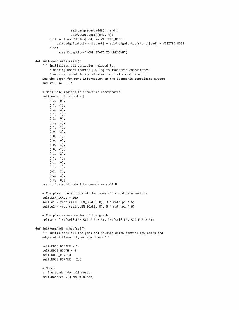
def initCoordinates(self):
''' Initializes all variables related to:
* mapping nodes indexes [0, 18] to isometric coordinates
* mapping isometric coordinates to pixel coordinate
See the paper for more information on the isometric coordinate system
and its use. '''
# Maps node indices to isometric coordinates
self.node_i_to_coord = [
( 2, 0),
( 2, -1),
( 2, -2),
( 1, 1),
( 1, 0),
( 1, -1),
( 1, -2),
( 0, 2),
( 0, 1),
( 0, 0),
( 0, -1),
( 0, -2),
(-1, 2),
(-1, 1),
(-1, 0),
(-1, -1),
(-2, 2),
(-2, 1),
(-2, 0)]
assert len(self.node_i_to_coord) == self.N
# The pixel projections of the isometric coordinate vectors
self.LEN_SCALE = 100
self.e1 = vrot((self.LEN_SCALE, 0), 3 * math.pi / 6)
self.e2 = vrot((self.LEN_SCALE, 0), 5 * math.pi / 6)
# The pixel-space center of the graph
self.c = (int(self.LEN_SCALE * 2.5), int(self.LEN_SCALE * 2.5))
def initPensAndBrushes(self):
''' Initializes all the pens and brushes which control how nodes and
edges of different types are drawn '''
self.EDGE_BORDER = 1.
self.EDGE_WIDTH = 4.
self.NODE_R = 10
self.NODE_BORDER = 2.5
# Nodes
# The border for all nodes
self.nodePen = QPen(Qt.black)

self.nodePen.setWidthF(self.NODE_BORDER)
# Diferent interiors
self.nodeBrush = QBrush(Qt.darkGreen)
self.startNodeBrush = QBrush(Qt.red)
self.endNodeBrush = QBrush(Qt.blue)
self.visitedNodeBrush = QBrush(Qt.yellow)
# Edges
# The border for all nodes
self.edgePenBorder = QPen(Qt.black)
self.edgePenBorder.setWidthF(self.EDGE_WIDTH + 2 * self.EDGE_BORDER)
# Different interiors
self.edgePen = QPen(Qt.cyan)
self.edgePen.setWidthF(self.EDGE_WIDTH)
self.visitedEdgePen = QPen(Qt.yellow)
self.visitedEdgePen.setWidthF(self.EDGE_WIDTH)
self.pathEdgePen = QPen(Qt.darkRed)
self.pathEdgePen.setWidthF(self.EDGE_WIDTH)
def setGraph(self, adj_mat):
''' Changes the graph (& resets search)'''
self.adj_mat = adj_mat
self.resetSearch()
def toPixels(self, coords):
''' Scales `coords` into pixel units '''
return vadd(vscale(self.e1, coords[0]), vscale(self.e2, coords[1]))
def getPixel(self, coords):
''' Turns `coords` into a vector indicating a pixel location on the
screen '''
return vadd(self.toPixels(coords), self.c)
def drawEdges(self, qp):
''' Draws all edges '''
for (i, j) in it.combinations(range(self.N), 2):
if self.adj_mat[i][j] == 1:
self.drawEdge(qp, i, j)
def drawEdgeLine(self, qp, ix, iy, jx, jy, pen):
''' Draws a line from `(ix, iy)` to `(jx, jy)` using the default edge
border, and `pen` for the interior of the edge '''
qp.setPen(self.edgePenBorder)
qp.drawLine(ix, iy, jx, jy)
qp.setPen(pen)
qp.drawLine(ix, iy, jx, jy)
def drawEdgeQuad(self, qp, ix, iy, cx, cy, jx, jy, pen):
''' Draws a quadratic bezier curve from `(ix, iy)` to `(jx, jy)`
controlled by `(cx, cy)` using the default edge border and `pen` for
the interior of the edge '''
qp.setPen(self.edgePenBorder)

path = QPainterPath()
path.moveTo(ix, iy)
path.quadTo(cx, cy, jx, jy)
qp.drawPath(path)
qp.setPen(pen)
path = QPainterPath()
path.moveTo(ix, iy)
path.quadTo(cx, cy, jx, jy)
qp.drawPath(path)
def getEdgePen(self, i, j):
''' Determines the correct pen (color) for the edge from `i` to `j` '''
if self.edgeStatus[i][j] == UNVISITED_EDGE:
return self.edgePen
elif self.edgeStatus[i][j] == PATH_EDGE:
return self.pathEdgePen
elif self.edgeStatus[i][j] == VISITED_EDGE:
return self.visitedEdgePen
else:
raise Exception('EDGE CODE IS UNKNOWN')
def drawEdge(self, qp, i, j):
''' Draws an edge from `i` to `j` using painter `qp` '''
# See the Final Report for a discussion of how we determine how much an edge
# should be curved.
self.assert_is_node(i)
self.assert_is_node(j)
icoord = self.node_i_to_coord[i]
jcoord = self.node_i_to_coord[j]
(ix, iy) = self.getPixel(icoord)
(jx, jy) = self.getPixel(jcoord)
diff = vdiff(jcoord, icoord)
gcd = abs(math.gcd(diff[0], diff[1]))
pen = self.getEdgePen(i, j)
if gcd == 1:
# Draw a straight edge
self.drawEdgeLine(qp, ix, iy, jx, jy, pen)
else:
# Draw a curved edge
half = vscale(diff, 0.5)
control_l = float(gcd) / (isomag(diff) * math.sqrt(3))
mult = control_l * (1 if gcd % 2 == 1 else -1)
control_diff = vrot(self.toPixels(vscale(diff, mult * control_l)), math.pi/2)
(cx, cy) = vadd(self.getPixel(vadd(icoord, half)), control_diff)
self.drawEdgeQuad(qp, ix, iy, cx, cy, jx, jy, pen)
def assert_is_node(self, i):
assert type(i) == int and i >= 0 and i < self.N
def getNodeBrush(self, i):
''' Determines the correct pen (color) for the node `i` '''
if self.nodeStatus[i] == NORMAL_NODE:
return self.nodeBrush
elif self.nodeStatus[i] == SOURCE_NODE:
return self.startNodeBrush

elif self.nodeStatus[i] == TARGET_NODE:
return self.endNodeBrush
elif self.nodeStatus[i] == VISITED_NODE:
return self.visitedNodeBrush
else:
raise Exception('NODE CODE IS UNKNOWN')
def drawNode(self, qp, i):
''' Draw the node `i` '''
self.assert_is_node(i)
qp.setBrush(self.getNodeBrush(i))
(x, y) = self.getPixel(self.node_i_to_coord[i])
qp.drawEllipse(x - self.NODE_R, y - self.NODE_R, 2 * self.NODE_R, 2 * self.NODE_R)
qp.drawText(x + self.NODE_R, y, str(i))
def drawNodes(self, qp):
''' Draws all nodes '''
qp.setPen(self.nodePen)
for i in range(self.N):
self.drawNode(qp, i)
def click_node_i(self, event):
''' Returns which node was click (the node's indexed) if any. Otherwise
returns `None` '''
ecoord = (event.x(), event.y())
for i in range(self.N):
d = vmag(vdiff(self.getPixel(self.node_i_to_coord[i]), ecoord))
if d < 11:
return i
return None
class Window(QWidget):
def __init__(self):
super().__init__()
self.initUI()
self.timer = QTimer()
self.timer.timeout.connect(lambda: self.doSearchStep())
self.timer.start(1000)
def paintEvent(self, e):
''' Repaints the GUI '''
# HACK:
# For some reason I don't yet understand, `paintEvent` only seems to
# run for the main window, not sub-widgets. To get around this, this
# window's paint event creates a painter that it then passes to the
# GraphWidget. The GraphWidget uses this painter to draw the graph in
# the coordinate system of the main window (rather than its own
# coordinate system). If the graph is moved out of the upper-left hand
# corner, this will stop working.
qp = QPainter()
qp.begin(self)
self.graphWidget.drawEdges(qp)
self.graphWidget.drawNodes(qp)
qp.end()

def setStartNode(self, i):
''' Sets `i` to the start node for search, if possible '''
if self.graphWidget.endNode != i:
self.startNode = i
self.graphWidget.startNode = i
self.graphWidget.resetSearch()
self.repaint()
def setEndNode(self, i):
''' Sets `i` to the end node for search, if possible '''
if self.graphWidget.startNode != i:
self.endNode = i
self.graphWidget.endNode = i
self.graphWidget.resetSearch()
self.repaint()
def mousePressEvent(self, event):
''' On mouse presses that occur on a node, left clicks cause that node
to become the source and right clicks cause that node to become the
target '''
node_i = self.graphWidget.click_node_i(event)
if node_i is not None:
if event.button() == Qt.LeftButton:
self.setStartNode(node_i)
elif event.button() == Qt.RightButton:
self.setEndNode(node_i)
super().mousePressEvent(event)
def initUI(self):
self.setGeometry(100, 100, 600, 600)
self.setWindowTitle('Graph Input')
self.graphWidget = GraphWidget(self)
self.readGraphButton = QPushButton('Read Graph')
self.readGraphButton.clicked.connect(self.readMatrix)
self.runSearchButton = QPushButton('Run Search')
self.runSearchButton.clicked.connect(self.startSearch)
hbox = QHBoxLayout()
hbox.addWidget(self.readGraphButton)
hbox.addStretch(1)
hbox.addWidget(QLabel('''
Left-click to set the (red) starting node.
Right-click to set (blue) ending node.
Hit "Run Search" to do Djikstra's!
'''))
hbox.addStretch(1)
hbox.addWidget(self.runSearchButton)
vbox = QVBoxLayout()
vbox.addWidget(self.graphWidget)
vbox.addStretch(1)
vbox.addLayout(hbox)
self.setLayout(vbox)
self.show()

self.readMatrix()
self.repaint()
def readMatrix(self):
''' Gets a new adjancency matrix and repaints the graph '''
self.graphWidget.setGraph(self.get_adjacency_matrix())
self.repaint()
def startSearch(self):
''' Starts the search (assuming the source and target have been set,
otherwise it does nothing) '''
print('search')
self.graphWidget.resetSearch()
self.graphWidget.searching = True
def doSearchStep(self):
''' If search is still in progress, executes one step '''
if self.graphWidget.searching:
self.graphWidget.step()
self.repaint()
def get_adjacency_matrix(self):
''' Spins up a child process which runs the `matrix` program to get the
adjacency matrix '''
p = subprocess.Popen(['matrix'], stdout=subprocess.PIPE,
stderr=subprocess.PIPE,
universal_newlines=True)
out, _ = p.communicate()
lines = out.split('\n')
matrix = [[int(c) for c in l] for l in lines]
print('\n'.join(lines))
return matrix
if __name__ == '__main__':
app = QApplication(sys.argv)
ex = Window()
sys.exit(app.exec_())
3. C Program (SPI Interface from the Pi) // Alex Ozdemir <[email protected]>
// Charlotte Robinson
// matrix.c
// 4 December 2016
////////////////////////////////////////////////
// Helpers
////////////////////////////////////////////////
#include <stdio.h>

#include "easypio.h"
const char *byte_to_binary(char x)
{
char z;
int i;
static char b[9];
b[9] = '\0';
for (z = 0b10000000, i = 0; z > 0; z >>= 1, i++)
{
b[i] = ((x & z) == z) ? '1' : '0';
}
return b;
}
////////////////////////////////////////////////
// Main
////////////////////////////////////////////////
void main(void) {
char in[50];
char matrix[20][21];
int i, j, r, c, Nout;
unsigned char k;
Nout = 19;
for (i = 0; i < 20; i++) {
matrix[i][21] = '\0';
}
pioInit();
spiInit(244000, 0);
// Transfer
SPI0CSbits.TA = 1;
spiSendReceive(0b00000001);
for (i = 0; i < 50; i++) {
in[i] = spiSendReceive(0);
}
SPI0CSbits.TA = 0;
// Reformat
for (i = 0; i < 50; i++) {
for (k = 0x80, j = 0; j < 8; j++, k >>= 1) {
r = (i * 8 + j) / 20;
c = (i * 8 + j) % 20;
matrix[r][c] = (k & in[i]) ? '1' : '0';
}
}
for (i = 0; i < Nout; i++) {
for (j = 0; j < Nout; j++) {
printf("%c", matrix[i][j]);
}
printf("\n");
}
}
4. Circuit Schematic (On the breadboard)


5. Circuit Schematic (On the FPGA)