
Granular Material Interactive Manipulation: Touching Sand...
7
Granular Material Interactive Manipulation: Touching Sand with Haptic Feedback Bedˇ rich Beneš Computer Graphics Technology Purdue University [email protected] Enkhtuvshin Dorjgotov Computer Graphics Technology, Purdue University [email protected] Laura Arns Envision Center, Purdue University [email protected] Gary Bertoline Envision Center, Purdue University [email protected] Abstract We present a novel approach for a virtual granular material interactive manipulation with force feedback. A user can interac- tively change a height-field model of sand by dragging objects inside. The virtual sand behaves like real sand moving to the sides and falling back, filling holes and irregularities on the surface. The dragging object position is controlled by a haptic de- vice that provides a position in 3D space that correspondingly changes the sand model. The sand model provides force feedback to the haptic device resulting in two principal forces; the repulse that has vertical direction and the viscous drag. The resulting force is delivered back to the haptic device. The user can sense the sand’s response as the dragging object moves through the virtual sand. This results in the haptic-visual feedback providing a higher degree of plausibility than visual feedback alone. Keywords: Sand, Tactile Devices, Virtual Reality, Simulating Natural Phenomena. 1 INTRODUCTION Terrain modeling algorithms and techniques published in the area of computer graphics such as [1, 2, 3, 5, 6, 11, 10, 14] have focused mostly on obtaining visually realistic physically-based models. Little attention has been paid to real-time and interactive techniques for producing realistic shapes of terrains. Interactive ma- nipulation techniques, such as [7, 8, 9, 13] mostly focus reaction of sand or soils to a certain user action. One of the first commercially successful applications provid- ing interactive terrain modeling was the Metacreations Bryce 3D R . We present a new algorithm for interactive modeling of sand shape using haptic devices. A user "touches" the virtual sand, which changes the shape correspond- ingly (see Figure 1). The potential users and applica- tions of this algorithm are anyone that needs to rapidly and realistically model the shape of sand. There are many interactive modelers for different data types. For example, there is the NURBS sculptor in MAYA R , hair painter in the same software, particles can be modeled in 3D MAX R and MAYA R , etc. The authors are not aware of any application that allows interactive model- ing of sand. The paper begins with a description of the previ- ously published modeling and simulating techniques that work with sand in the area of computer graphics. Permission to make digital or hard copies of all or part of this work for personal or classroom use is granted without fee provided that copies are not made or distributed for profit or commercial advantage and that copies bear this notice and the full citation on the first page. To copy otherwise, or republish, to post on servers or to redistribute to lists, requires prior specific permission and/or a fee. WSCG 2006 conference proceedings, ISBN 80-86943-03-8 WSCG’2006, January 30 – February 3, 2006 Plzen, Czech Republic. Copyright UNION Agency – Science Press In Section 3 we describe the real-time modeling and displaying of sand, and Section 4 describes the haptic device and the force feedback from the sand. Section 5 discusses the implementation issues and the last part shows results of our experiments and concludes the pa- per. Figure 1: WSCG written in sand 2 RELATED WORK The previous work can be roughly divided into two sig- nificant classes: the real-time algorithms and the non- real-time algorithms. We will first discuss the histori- cally older group of non-real-time algorithms. 2.1 Non-Real-time Sand Manipulation Probably the first paper dealing with sand simulation is the erosion simulation algorithm of Musgrave et al [10]. Material is described as a regular height field and is eroded by thermal and hydraulic erosion. Some parts are broken by the thermal shocks and fall down. Some amount of material is dissolved by running water and deposited to a different location. The shape morphol- ogy is described as a set of parameters that defines the material properties. Sumner et al [13] introduced a technique for animat- ing sand and soil motion that results from interactions
-
Upload
hoanghuong -
Category
Documents
-
view
218 -
download
1
Transcript of Granular Material Interactive Manipulation: Touching Sand...

Granular Material Interactive Manipulation:Touching Sand with Haptic Feedback
Bedrich BenešComputer Graphics Technology
Purdue [email protected]
Enkhtuvshin DorjgotovComputer Graphics Technology,
Purdue [email protected]
Laura ArnsEnvision Center,
Purdue [email protected]
Gary BertolineEnvision Center,
Purdue [email protected]
Abstract
We present a novel approach for a virtual granular material interactive manipulation with force feedback. A user can interac-tively change a height-field model of sand by dragging objects inside. The virtual sand behaves like real sand moving to thesides and falling back, filling holes and irregularities on the surface. The dragging object position is controlled by a haptic de-vice that provides a position in 3D space that correspondingly changes the sand model. The sand model provides force feedbackto the haptic device resulting in two principal forces; the repulse that has vertical direction and the viscous drag. The resultingforce is delivered back to the haptic device. The user can sense the sand’s response as the dragging object moves through thevirtual sand. This results in the haptic-visual feedback providing a higher degree of plausibility than visual feedback alone.
Keywords: Sand, Tactile Devices, Virtual Reality, Simulating Natural Phenomena.
1 INTRODUCTION
Terrain modeling algorithms and techniques publishedin the area of computer graphics such as [1, 2, 3, 5, 6,11, 10, 14] have focused mostly on obtaining visuallyrealistic physically-based models. Little attention hasbeen paid to real-time and interactive techniques forproducing realistic shapes of terrains. Interactive ma-nipulation techniques, such as [7, 8, 9, 13] mostly focusreaction of sand or soils to a certain user action. One ofthe first commercially successful applications provid-ing interactive terrain modeling was the MetacreationsBryce 3D R©.
We present a new algorithm for interactive modelingof sand shape using haptic devices. A user "touches"the virtual sand, which changes the shape correspond-ingly (see Figure 1). The potential users and applica-tions of this algorithm are anyone that needs to rapidlyand realistically model the shape of sand. There aremany interactive modelers for different data types. Forexample, there is the NURBS sculptor in MAYA R©, hairpainter in the same software, particles can be modeledin 3D MAX R© and MAYA R©, etc. The authors are notaware of any application that allows interactive model-ing of sand.
The paper begins with a description of the previ-ously published modeling and simulating techniquesthat work with sand in the area of computer graphics.
Permission to make digital or hard copies of all or part of thiswork for personal or classroom use is granted without fee providedthat copies are not made or distributed for profit or commercialadvantage and that copies bear this notice and the full citation on thefirst page. To copy otherwise, or republish, to post on servers or toredistribute to lists, requires prior specific permission and/or a fee.
WSCG 2006 conference proceedings, ISBN 80-86943-03-8WSCG’2006, January 30 – February 3, 2006Plzen, Czech Republic.Copyright UNION Agency – Science Press
In Section 3 we describe the real-time modeling anddisplaying of sand, and Section 4 describes the hapticdevice and the force feedback from the sand. Section 5discusses the implementation issues and the last partshows results of our experiments and concludes the pa-per.
Figure 1: WSCG written in sand
2 RELATED WORK
The previous work can be roughly divided into two sig-nificant classes: the real-time algorithms and the non-real-time algorithms. We will first discuss the histori-cally older group of non-real-time algorithms.
2.1 Non-Real-time Sand Manipulation
Probably the first paper dealing with sand simulation isthe erosion simulation algorithm of Musgrave et al [10].Material is described as a regular height field and iseroded by thermal and hydraulic erosion. Some partsare broken by the thermal shocks and fall down. Someamount of material is dissolved by running water anddeposited to a different location. The shape morphol-ogy is described as a set of parameters that defines thematerial properties.
Sumner et al [13] introduced a technique for animat-ing sand and soil motion that results from interactions

with tools. Their technique is able to simulate materialdisplacement that results from footsteps and trails in thesand and mud.
An interesting approach for modeling wind ripplesin sand was shown by Onoue and Nishita [7]. The sandparticles reallocation is formed by the two principal fac-tors - creep and saltation. These phenomena are de-scribed by a set of equations that is applied to the sandmodel represented as a regular height field.
Beneš and Forsbach [1] introduced a layered datastructure that allows for representation of volumetriceffects, such as caves, as well as for a surface erosion.They use a RLE-like data structure that represents lay-ers of deposited material. This volumetric techniquereports comparable speed of erosion simulation as inthe case of height-fields that is significantly better thanvoxel-based approaches.
Zhu and Birdson [14] recently presented applicationof the Navier-Stokes equations to simulation of sandmotion. Sand is represented as a cloud of particles andits motion is described by the physically correct equa-tions. Special attention is paid to the surface trackingand rendering.
2.2 Real-time Sand ManipulationThe real-time manipulation algorithms are representedby the following previous work.
Li and Moshell in [9] described a physically-basedmodel of real-time digging and caving. The modelworks with extended regular height-fields and describesthe surface changes.
The papers [1, 13] were the motivation for the VirtualSandbox of Onoue and Nishita [8]. Real-time manipu-lation of sand is described by the dual sand represen-tation; as a height field and as a set of particles. Parti-cles are used for sand that is elevated over the surfaceof the height-field and the height-field is used for de-posited sand. The authors report interactive frame ratesfor sand manipulation and interaction.
Neidhold et al [11] recently introduced another algo-rithm for terrain shape morphology that deals with ho-mogenous sand-like structures and allows for real-timehydraulic erosion simulation.
All of the previous work focuses on shape morphol-ogy and the interaction is limited to the user workingwith a mouse as an input device or to real-time dis-playing of erosion processes. We propose a haptic-device interaction that provides another level of fidelityto users who interact with the granular material model.
3 REAL-TIME SAND SIMULATIONOne of the principal advantages of sand, from the view-point of modeling in computer graphics, is the factthat it cannot form concave structures. That is whysand is usually represented as a regular height-field; a
two dimensional matrix, where each vertex correspondsto the elevation of the given location. The elevationpoints are regularly sampled in two dimensional space,which simplifies algorithms for the terrain metamor-phosis simulation. On the other hand this representationis space demanding. Regardless of the level of detail orthe amount of terrain roughness the amount of spaceoccupied is the same. We use regular height-fields tostore the model of the sand.
There are two aspects of the sand manipulation to beconsidered. The sand relocation by user action (dis-placement) and sand returning to the stable position bygravity (erosion). Our algorithm is a two pass algo-rithm. In the first pass the user contacts the sand with avirtual tool and the dragging displaces a certain amountof the material. In the second pass the sand is erodedback. We will describe both passes in depth.
3.1 Sand displacement
As an object penetrates the sand surface it displaces acertain amount of the granular material. This displace-ment depends on the force vector that represents thedrag direction, the collision area between the object,and on the object and the sand boundary shape. Theforce is responsible for the depth the objects enter thegranular material, and its shape determines the amountof pushed sand. General calculation can be very de-manding, but careful scene preparation can simplify it.
We use a sphere as the dragging object. It has theprincipal advantage of having the same shape facing thesand regardless of dragging direction. The amount ofdisplaced material can be easily determined.
-0.5
-0.4
-0.3
-0.2
-0.1
0
0.1
0.2
0.3
0.4
0.5
-1.5 -1 -0.5 0 0.5 1 1.5
sin(x*x)-0.5
Figure 2: The cross-section of the filter applied to re-place the sand
To make the calculation even faster we introduce aconcept of two two dimensional erosion discrete filters.The first one has circular shape and corresponds to thearea that penetrates the sand and all values in this fil-ter are negative. We denote this filter by negi, j. Theother filter has positive values, has a shape of circularrampart, and is located around the negative filter. It isdenoted by posi, j. The sum of the integrals over both
filters is zero which reflects the volume preservationcondition.
∞
∑i=−∞
∞
∑j=−∞
negi, j +∞
∑i=−∞
∞
∑j=−∞
posi, j = 0.
Both filters are displayed in one image in Figure 2.The inner part begins in the inflexion points of the curveand it is the neg filter. The rest is the outer part i.e., thepos filter. The discrete filters result from sampling acontinuous function that has the form
negx,y = sin(x2 + y2)−0.53,√
x2 + y2 > 1.2,
posx,y ={
sin(x2 + y2)−0.53 1.63 <√
x2 + y2 ≤ 1.2,0 otherwise
When the dragged object penetrates the sand we firstapply the circular negative filter. Based on the depth ofthe impact, the filter values are shifted by a constant co-efficient and the sum of the values from this filter andthe terrain is calculated. The result of this operation isone number which is the amount of the material that thesphere pushes out. At the same time, the negative val-ues are added to the terrain that removes the material.
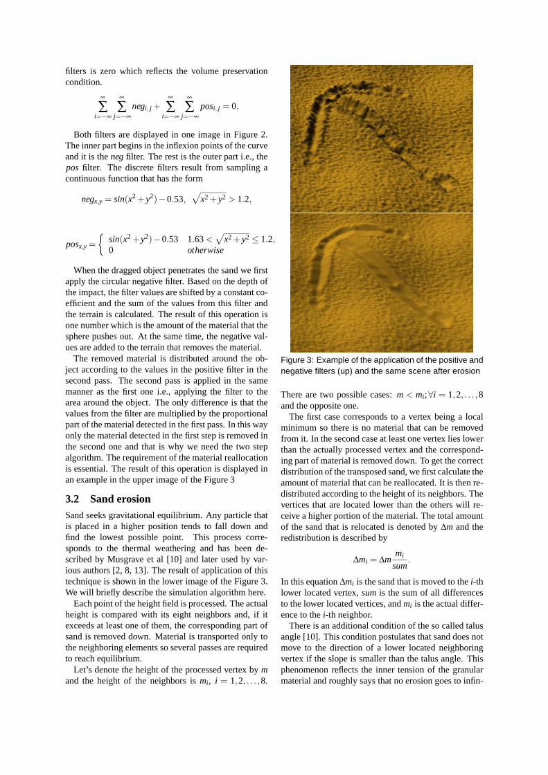
The removed material is distributed around the ob-ject according to the values in the positive filter in thesecond pass. The second pass is applied in the samemanner as the first one i.e., applying the filter to thearea around the object. The only difference is that thevalues from the filter are multiplied by the proportionalpart of the material detected in the first pass. In this wayonly the material detected in the first step is removed inthe second one and that is why we need the two stepalgorithm. The requirement of the material reallocationis essential. The result of this operation is displayed inan example in the upper image of the Figure 3
3.2 Sand erosionSand seeks gravitational equilibrium. Any particle thatis placed in a higher position tends to fall down andfind the lowest possible point. This process corre-sponds to the thermal weathering and has been de-scribed by Musgrave et al [10] and later used by var-ious authors [2, 8, 13]. The result of application of thistechnique is shown in the lower image of the Figure 3.We will briefly describe the simulation algorithm here.
Each point of the height field is processed. The actualheight is compared with its eight neighbors and, if itexceeds at least one of them, the corresponding part ofsand is removed down. Material is transported only tothe neighboring elements so several passes are requiredto reach equilibrium.
Let’s denote the height of the processed vertex by mand the height of the neighbors is mi, i = 1,2, . . . ,8.
Figure 3: Example of the application of the positive andnegative filters (up) and the same scene after erosion
There are two possible cases: m < mi;∀i = 1,2, . . . ,8and the opposite one.
The first case corresponds to a vertex being a localminimum so there is no material that can be removedfrom it. In the second case at least one vertex lies lowerthan the actually processed vertex and the correspond-ing part of material is removed down. To get the correctdistribution of the transposed sand, we first calculate theamount of material that can be reallocated. It is then re-distributed according to the height of its neighbors. Thevertices that are located lower than the others will re-ceive a higher portion of the material. The total amountof the sand that is relocated is denoted by Δm and theredistribution is described by
Δmi = Δmmi
sum.
In this equation Δmi is the sand that is moved to the i-thlower located vertex, sum is the sum of all differencesto the lower located vertices, and mi is the actual differ-ence to the i-th neighbor.
There is an additional condition of the so called talusangle [10]. This condition postulates that sand does notmove to the direction of a lower located neighboringvertex if the slope is smaller than the talus angle. Thisphenomenon reflects the inner tension of the granularmaterial and roughly says that no erosion goes to infin-

ity. Depending on material, equilibrium is reached ata faster or slower pace. Especially in the case of sand,the talus angle is found very quick, as everyone whohas visited the beach has probably experienced. Whendigging a hole in the sand, it is filled very fast but onlythe hole boundary is softened. This is shown in the Fig-ure 4, where a scene was set up in such a way to demon-strate the phenomenon.
Figure 4: Sand finds the talus angle fast
Setting the value of the talus angle is essential for thespeed of erosion. Erosion weakens exponentially andit does not make any sense to keep the angle close tozero. A small talus angle only keeps the algorithm run-ning without a significant visual effect. On the otherhand high talus angle values causes the granular mate-rial to look very rough. We have experienced a reason-able value of the talus angle to be around 30o.
4 TOUCHING THE SANDThe fundamentally new approach in this paper is usinghaptic devices to interact with a material that is a subjectof metamorphosis at the same time.
Sand is a special case of a granular material andis an extremely complicated subject that is studied inphysics. This is primarily because the forces inside thematerial are not well-known yet. Granular material canbe considered as a tight particle system. Each particlehas its stickiness, surface area, mass, and shape. As anexternal force is applied the particles on the surface ro-tate and move and the forces are transferred inside thevolume. This presents a vast amount of forces that aredistributed inside the granular material. Obviously, the
force distribution depends heavily on the size of the par-ticles and their stickiness (humidity is an important fac-tor here). The above described qualitative model can besubstituted by a quantitative one using reasonable sim-plifications.
4.1 ForcesWe propose a model of sand interaction to a force underthe following conditions [12]. The penetrating object isa sphere. It has the major advantage that its interactionarea is the same regardless of the direction the spheremoves. This allows us to drop-off area-to-sand calcula-tions and this increases the speed of simulation. Sandis homogenous in our calculations. There are no lay-ers with higher humidity, there are no crunchy shells onthe surface, no cracks, nor bubbles or stones. Based onthese assumptions we set up a set of equations that de-scribe the force feedback of the sand to the penetratingobject. The forces are then sent to the input of the hapticdevice which provides the corresponding feedback.
The resulting force has two important components.The vertical repulse force and the horizontal friction ascan be seen in Figure 5.
vF
F
R
F
Sand
Object
Figure 5: An object entering the sand is repulsed bythe vertical force and dragged by friction
The repulse force results from the increasing tensionwith the depth of the sand. The repulse force has theopposite direction to the normal vector to the surface,close to the surface, and becomes vertical with increas-ing depth. The repulse function has the form
�Fr = −ksekcd −1 (1)
where ks, kc are the material dependent constantsand d is the depth of the layer of sand. This force hasalways vertical, or nearly vertical direction. We usethe strictly vertical direction in our simulations, sincethe sand erodes quickly to the talus angle, as describedin Section 3. The angle is small so the normal vectorto the surface is nearly vertical. The difference isimpossible to feel.
The second force is the inner friction of the sand thathas only the vertical component. It is also a function ofdepth but it is higher with the velocity. The equation offriction is
�Ff = −k�F|�Fr|. (2)

The force �F depends on the friction area, the velocity�v,and the size of the repulse force �Fr. The friction area isconstant so �F = ka�v. We can accumulate the constantsk f = k ka obtaining
�Ff = −k f�v|�Fr|. (3)
The three constants depend on the implementationand the relative sizes of the other objects in the scene.Having the total sand area of size 〈−1,1〉2 and thesphere radius equal to 0.01, the ks = 103, kc = 1/2 andk f = 10.
Figure 6 demonstrates the use of force on one stroke.The stroke starts with a strong vertical force that weak-ens. This causes more material to be removed at thebeginning. The sand after it is touched by the sphereimmediately erodes-out the differences.
Figure 6: An example of the stroke with varying forceapplied. The stroke starts with a stronger force andends with a smaller one as can be seen by the amountof the removed material
4.2 Haptic Devices
Figure 7: The 6DOF Phantom (left) and the 3DOF-Omega haptic device
Our sand drawing application currently works withthe 3-DOF Omega(tm) haptic device and 6-DOF Phan-tom(tm) Desktop haptic device (Figure7), both pro-vided by The Force Dimension(tm). These two hapticdevices provide an affordable desktop solution that issuitable for our application. The Omega(tm) haptic de-vice is connected to a PC by the USB port and providesresolution of 0.009mm and maximum force feedback
of 12N. The Phantom(tm) is connected via the paral-lel port and provides 0.03mm resolution, but goes upto 20N and has six degrees of freedom. Both devicesprovide full gravity compensation.
Figure 8: Scene setup
5 IMPLEMENTATION
The entire system is implemented in C++. We useOpenGL(r) for visualization and the CHAI 3D open-source haptic rendering library [4] for interaction. Wehave chosen the CHAI 3D library because of its trans-parent support for several haptic devices including theOmega(tm) family, the Delta(tm), and the Phantom(tm)devices. This library is provided in source code and iseasily extendible for other haptic devices.
The sand drawing application consists of two majorparts; the graphics (visualization) part and the hapticinteractive device. Both parts work together to imitatedrawing on sand with haptic feedback.
In each haptic rendering loop, we read the actual po-sition of the haptic device in 3D space. We transform itas a position of the virtual device and if it is inside thesand surface we compute the responding forces. Theseforces are applied to the sand surface and it is indicatedthat the area should be eroded. The erosion step, that isactually slow, takes place outside the main haptic loop.
The update rates of these two loops are very differentsince a visual rendering needs a much slower refreshrate compared to a haptic update rate. While a 60Hzrefresh rate is standard for visual rendering, the hapticrendering requires at least a 1kHz update rate to providesmooth haptic feedback to a human user. In our ap-plication, we use a high frequency timer for the hapticfeedback so that the haptic rendering loop takes placein every millisecond. The commands in the haptic loopare not buffered. Once entered the callback applicationdoes not execute the same routine until it is terminated.If there is some piece of code that takes a long time,the newly generated position can be much farther. Thehaptic loop is no reentrant. It is important to keep allthe complicated calculations out of the haptic loop anduse it just for setting some variables. Actually, synchro-nization of the visual and the haptic loops presents aninteresting problem in general.

Slowing down the application while inside the call-back of the haptic loop is especially difficult whenchanging the depth of the virtual pointer. The force ina shallow depth is small and when deeper it is muchhigher. According to equation (1) the feedback is anexponential function of depth. Wrongly implementedhaptic feedback can cause jumps and sudden abruptforces. A very strong vertical force on a slow feedbackcould move the virtual pointer too deep into the granu-late material. The haptic device produces a very strongback force in such cases.
There are not major issues in the rendering loop. Oneof the important parts, from the viewpoint of speed,is to update continuously only the areas that are reallychanged. To achieve this we divide the regular heightfield area into a set of 10x10 OpenGL display lists.Once the user makes a stroke, only the affected displaylists are updated. Once the area is eroded (all the anglesin the simulated area are smaller than the talus angle)and no material is moved, the display lists are not up-dated anymore. Technically this means that the systemis slowest when there are many areas eroded (touched)at the same time. This is technically difficult, becausethe erosion reaches equilibrium fast.
6 CLOSING REMARKS
The system provides interactive feedback for height-fields up to 1000x1000 vertices (2MΔ). The systemruns at 60fps on a Dell Precision M70 laptop running at1.6GHz with the NVIDIA Quadro FX Go 1440 graph-ics card.
The haptic feedback does provide a higher level offidelity than using only visual feedback. This can beeasily tested by disabling the force feedback on the hap-tic device and manipulating the sand directly by mouse.We have tried a mouse but found the haptic feedbackgives much better results.
The sequence of images in Figures 9-12 shows thesuccessive modeling of a granular surface. The imagesare frames from the accompanying video. These im-ages show the result of successive editing of granularmaterial using our system.
We have demonstrated that implementation of inter-active sand sculpting system with haptic feedback ispossible and leads to better results than just visual feed-back. We believe that future applications of our ap-proach could be as a plug-in for some professional sys-tems such as Maya(r), or 3D Studio MAX(r). We be-lieve it would be much better to model complex scenesby simple haptic feedback and the user could then testcomplicated animation sequences in this way as well.
There are still many open areas and future workshould focus on the following unsolved problems:
• dragging arbitrary shapes and correct repulse calcu-lation based on the actual intersection area,
Figure 9: Sequence of images demonstrating succe-sive editing of a granular material (image 1)
Figure 10: image 2
• correct material manipulation,
• including non-homogenous surfaces, shells, stones,wet sand, and
• including sand in the air (for example as free parti-cles as done in the work of Onoue and Nishita [8])and
Figure 11: image 3

Figure 12: image 4
• improving control over the haptic device and therendering loop.
There is one last interesting observation. The hapticfeedback is incomparably better than just a visual feed-back as we tested when just using a mouse instead ofthe Phantom(tm) device. On the other hand, using thehaptic devices intensively, for more than four hours inthe case of the final tuning the application, causes verystrong pain in the arm next day. This is certainly an as-pect that should be considered. The forces that a userhas to support are up to 3 N, which means manipulat-ing 3kg of material with one hand. Doing this for a longperiod of time is certainly good exercise for the user.
REFERENCES[1] B. Beneš and R. Forsbach. Layered Data Structure for Visual
Simulation of Terrain Erosion. In SCCG ’01: Proceedingsof the 17th Spring conference on Computer graphics, volume25(4), pages 80–86. IEEE Computer Society, 2001.
[2] B. Beneš and R. Forsbach. Visual simulation of hydraulic ero-sion. Journal of WSCG, 10(1):79–86, 2002.
[3] N. Chiba, K. Muraoka, and K. Fujita. An erosion model basedon velocity fields for the visual simulation of mountain scenery.The Journal of Visualization and Computer Animation, 9:185–194, 1998.
[4] F. Conti, F. Barbagli, R. Balaniuk, M. Halg, C. Lu, and D. Mor-ris. The CHAI libraries. In Proceedings of Eurohaptics 2003,pages 496–500, Dublin, IE, July 6–9 2003.
[5] J. Dorsey, A. Edelman, H. W. Jensen, and H. .K Pedersen. Mod-eling and Rendering of Weathered Stone. In Proceedings ofSIGGRAPH ’99, volume 25(4) of Computer Graphics Proceed-ings, Annual Conference Series, pages 225–234. ACM, ACMPress / ACM SIGGRAPH, 1999.
[6] T. Ito, T. Fujimoto, K. Muraoka, and N. Chiba. Modeling rockyscenery taking into account joints. In Computer Graphics In-ternational, pages 244–247, 2003.
[7] O. Koichi and T. Nishita. A Method for Modeling and Render-ing Dunes with Wind-ripples. In Proceedings of Pacific Graph-ics’00, pages 427–428, 2000.
[8] O .Koichi and Tomoyuki. Nishita. Virtual sandbox. In Proceed-ings of Pacific Graphics’03, pages 252–260. IEEE ComputerSociety, 2003.
[9] X. Li and M. Moshell. Modeling Soil: Realtime Dynamic Mod-els for Soil Slippage and Manipulation. In Proceedings of SIG-GRAPH’93, volume 27(4) of Annual Conference Series, pages361–368, 1993.
[10] F.K. Musgrave, and C.E. Kolb, and R.S. Mace. The Synthesisand Rendering of Eroded Fractal Terrains. In Proceedings ofSiggraph’89, volume 23(3) of Annual Conference Series, pages44–50, 1989.
[11] B. Neidhold, and M. Wacker, and O. Deussen Interactive phys-ically based Fluid and Erosion Simulation. In Proceedingsof Eurographics Workshop on Natural Phenomena, volume 1,pages 25–32, 2005.
[12] G.N. Smith and G.N. Ian Smith. Elements of Soil Mechanics.Blackwell Science Profesional, 1998.
[13] R. W. Sumner, J. F. O’Brien, and J. K. Hodgins. AnimatingSand, Mud, and Snow. Computer Graphics Forum, 18(1):17–26, 1999.
[14] Y .Zhu and R. Bridson. Animating sand as a fluid. ACM Trans.Graph., 24(3):965–972, 2005.