GRADUAL DAΦNE UPGRADE TOWARDS L = 6*10 … · GRADUAL DAΦNE UPGRADE TOWARDS L = 6*1032 cm-2 s-1...
31
GRADUAL DAΦNE UPGRADE TOWARDS L = 6*10 32 cm -2 s -1 Catia Milardi for the Accelerator Division
Transcript of GRADUAL DAΦNE UPGRADE TOWARDS L = 6*10 … · GRADUAL DAΦNE UPGRADE TOWARDS L = 6*1032 cm-2 s-1...

GRADUAL DAΦNE UPGRADETOWARDS L = 6*1032 cm-2 s-1
Catia Milardifor the Accelerator Division

KLOE => FINUDA (2nd run) (Apr ÷ Jul 2006)
FINUDA => SIDDHARTA (half 2007)
SIDDHARTA => FINUDA (3rd run) (spring 2008)
DAΦNE present plan
During the shutdowns between differentexperiments several upgrades shouldbe implemented relying on the followingideas …
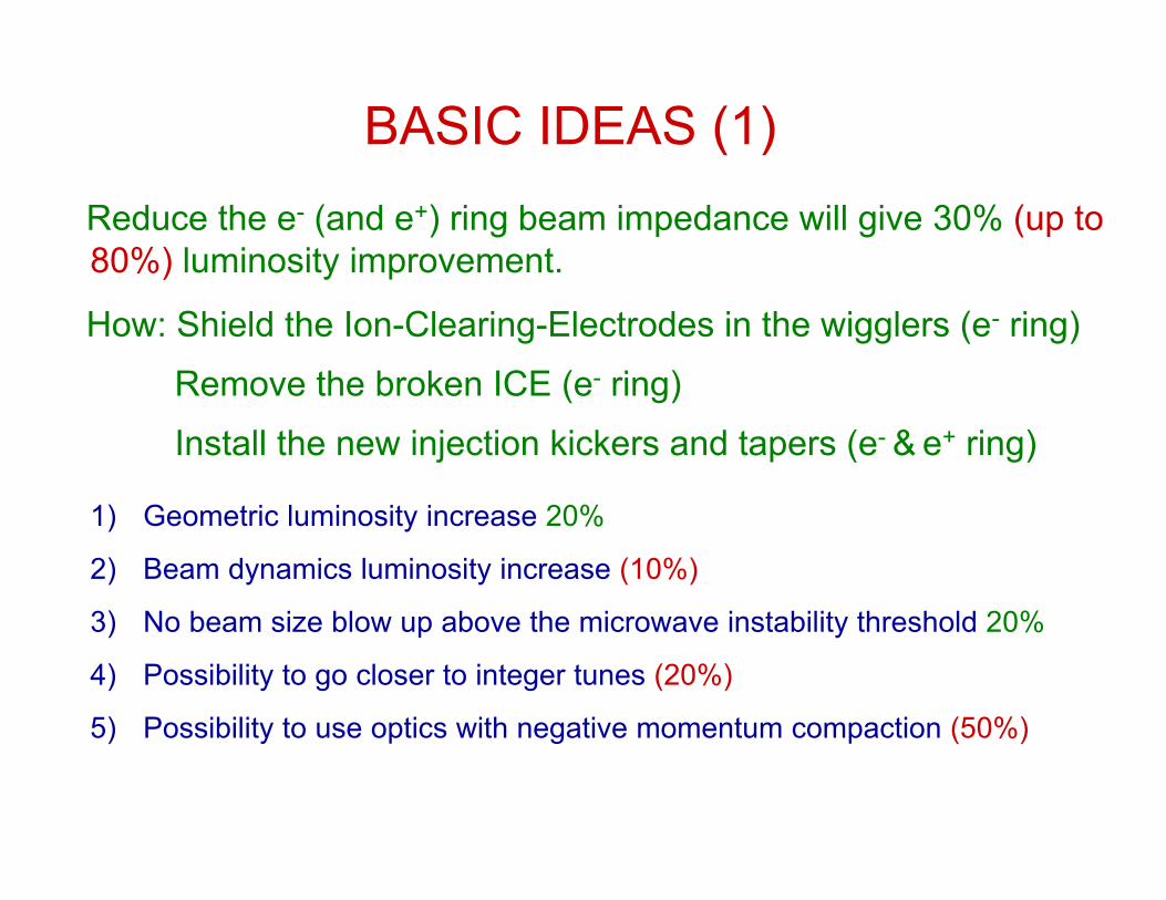
BASIC IDEAS (1)
Reduce the e- (and e+) ring beam impedance will give 30% (up to80%) luminosity improvement.
How: Shield the Ion-Clearing-Electrodes in the wigglers (e- ring)
Remove the broken ICE (e- ring)
Install the new injection kickers and tapers (e- & e+ ring)
1) Geometric luminosity increase 20%
2) Beam dynamics luminosity increase (10%)
3) No beam size blow up above the microwave instability threshold 20%
4) Possibility to go closer to integer tunes (20%)
5) Possibility to use optics with negative momentum compaction (50%)

MOTIVATION:• Impedance of the DAFNE Main Rings:
• Impedance affects bunch length:
σz- ≈ 2.7cm
σz+ ≈ 2 cm measured @ Ib ~ 15 mA
REALIZATION:• by means of removable metal plates (CuBe .25 mm thick) covering the ICE
GOALS:• a factor 2 reduction in e- ring impedance
e+
e-difference mainly due to Ion Clearing Electrodesin the Wigglers!
Shielding the Ion Clearing Electrodes in the Wigglers
3/13/1
6/12
o
z
nZ
R
≈
ξ
πσ
( ) cRFs
c
hVI
eE
Iφ
π
ν
αξ
cos2
/2==
€
Zn
0≈ 0.54Ω
€
Zn
0≈1Ω

10
15
20
25
30
35
0 10 20 30 40
I [mA]
e+ ring
e- ring
Bunch Length [mm]
0,15
0,2
0,25
0,3
0,35
0,4
50 100 150 200 250 300
1.5 mA9 mA19 mA
V [kV]
σy [mm]
Impedance Effects in the e- Ring
Stronger Bunch Lengthening Vertical Size Blow f(VRF, Ib)

921.3 (sim.)1.4 (sim.)Low Impedance
Negative αc
182.12.3Low Impedance
02.1 (meas.)3.0 (meas.)Normaloperations
Gain, %σz (e+), cmσz (e-), cmConditions
GEOMETRIC LUMINOSITY GAIN
( ) ( )22 −+ + zz σσIf βx,y scale as

BASIC IDEAS (2)
Increase the Positron Beam Current to 2Amps.
How:
1) New injection kickers (less beam impedance, less beam excitation)
2) Ti-coating against electron cloud
3) New transverse feedbacks (one experimental sample is already running at DAΦNE)

0
5 1031
1 1032
1.5 1032
2 1032
2.5 1032
0 1 106 2 106 3 106 4 106 5 106
Luminosity fit versus I + * I-measured LuminosityL = 2.24 10 32 I+= 2A I-= 2A Lu
min
osity
[cm-2
s-1
]
I+ * I- [mA2]
Luminosity gain increasing the currents of the colliding beams

NEW DAFNE INJECTION KICKERSNEW DAFNE INJECTION KICKERS
present pulse length ~150ns(old kickers)
tt
VT
VT
aimed FWHM pulse length ~5.4 ns
E=510 Mev# of bunches=120(max)Stored currents=1.5A e+, 2.0A e-
K
K
K
K
(D. Alesini and F. Marcellini)
presenpresen
50 bunches1 bunch

BASIC IDEAS (3)• Feedback upgrades [A.Drago]
The present low energy DAFNE shifts have pointed outthe major limits of the beam dynamics control.
What we need is:
I) More e- feedback power (+750W) to better control thelongitudinal instabilities and avoid the beam-beam in-collision blow-up’s (e- beam)
II) More feedback selected gain to control the transverseinstabilities using the new SLAC-KEK modules FPGA based (e+ inboth planes, eventually e- in both planes)
III) Complete remote control & monitoring of feedbacks and beamdynamics to give a faster and better diagnostics from outsideDAFNE control room (e+/e- beam)
• Possibly 25-30% increase in peak luminosity and 30-35%in integrated

BASIC IDEAS (4)
Increase the Lifetime.
How:
1) Wigglers modifications will give a factor 2(up to 4)
2) Parasitic crossings compensation withcurrent-carrying wires (first trial successful).Lifetime independent from the other beam current.
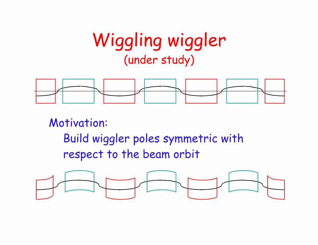
Wiggling wiggler(under study)
Motivation:Build wiggler poles symmetric withrespect to the beam orbit

Multipole budget(with respect to standard wiggler)
15%Octupole
55%Sextupole
25%Quadrupole
Goals:• increase Lint
• increase Lpeak

0.08
0.1
0.12
0.14
0.16
0.18
0.2
0.22
0.24
-0.01 -0.005 0 0.005 0.01
νx KLOE
2002νy KLOE2002νx FINUDA2004νy FINUDA2004
ν x,y
Δp/p
• Magnetic Measurements show:- 3rd order term reduced by 2.5
• Tests using the beam- confirm magnetic measurements- show a factor 2 in the energy acceptance
m2x m2y
KLOE 2002 -882 823FINUDA 2004 -194 -144
€
ν x = ν x0 + m1xΔpp
+ m2xΔpp
2
€
ν y = ν y0 + m1yΔpp
+ m2yΔpp
2
e+

Parasitic Crossings compensation in the DAFNEInteraction Region
Windings OFF Windings ON Windings ON(wrong polarity)
Particle equilibrium density in the transverse space ofnormalized betatron amplitude
MOTIVATION:• In the DAFNE Irs the beams experience 24 Beam Beam Long Rangeinteractions limiting the maximum storable current.•Numerical simulations show that BBLR interactions can be compensatedby current-carrying windings

Z = 4.887 m
IP1compensation winding
KLOE half IR simplified top view
Splitter
x
compensation winding(20 coils)
y
I
I
L = .215 m
z
L = .18 m
REALIZATION:• Windings installed in the KLOE Interaction Region

1000
1200
1400
1600
1800
2000
Dec/3/2005 6:00:00 Dec/3/2005 9:00:00 Dec/3/2005 12:00:00 Dec/3/2005 15:00:00 Dec/3/2005 18:00:00 Dec/3/2005 21:00:00
20051203dat
tau + [s] (wire current .9 A)tau + [s] (wire current 3.6 A)
τ+ [s]
Time
500
1000
1500
2000
Dec/3/2005 6:00:00 Dec/3/2005 9:00:00 Dec/3/2005 12:00:00 Dec/3/2005 15:00:00 Dec/3/2005 18:00:00 Dec/3/2005 21:00:00
20051203dat
I- [mA] (wire current .9 A)I+ [mA] (wire current .9 A)I- [mA] (wire current 3.6 A)I+ [mA] (wire current 3.6 A)
I [m
A]
Time
First results from BBLR compensation windings
... with the same currents
τ+ improves
τ+ affects:I+MAX
Lint
background

BASIC IDEAS (5)
Decrease coupling, betay,chromaticity,bb-parasitic crossing. How:
New interaction region for Dear andFinuda2. Low betay peak, earlierseparation of beam lines. QFs onseparate lines.
1) Geometric luminosity increase 20%
2) Beam dynamics luminosity increase 10% (20%)

BASIC IDEAS (6)
Remove the horizontal crossing angle.
How:
Install 1 crab cavity per ring.
Geometric luminosity increase 10%
Beam dynamics luminosity increase 20% (70%)

The crab crossing optimizes the geometricalsuperposition of the colliding bunches
Studies on B-factories optimization shown thatthe beam-beam effects are weaken by the crabcrossing. An increase in luminosity up to afactor of 2 is expected (K. Ohmi, PRST-AB,2004)
weak-strongsimulations
Crab crossing system for DAFNE: luminosity increase
0.4310φcrab=15 mrad
0.7510φcrab=0 mrad
0.696φcrab=15 mrad
0.886φcrab=0 mrad
L/L0I [mA]
DAFNE at present tunesLIFETRAC simulations
DAFNE at present β*Analytic calculation

Crab crossing system for DAFNE: RF cavities
Different approaches to damp the HOMand LFM can be adopted (see K. Akaidesigns, KEK)
RcL
Main dimensions [cm] (pillbox case)
∼12∼101472 (4th harmonic)
∼ 16∼141104 (3rd harmonic)
∼ 23∼20736 (2nd harmonic)
∼ 47∼40368 (found. harmonic)
Frequency of operation[MHz]
Rc
L
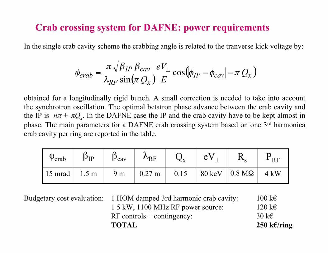
Crab crossing system for DAFNE: power requirements
( )( )xcavIP
xRF
cavIPcrab Q
EeV
Qπφφ
πλ
ββπφ −−= ⊥ cos
sin
In the single crab cavity scheme the crabbing angle is related to the tranverse kick voltage by:
obtained for a longitudinally rigid bunch. A small correction is needed to take into accountthe synchrotron oscillation. The optimal betatron phase advance between the crab cavity andthe IP is nπ + πQx. In the DAFNE case the IP and the crab cavity have to be kept almost inphase. The main parameters for a DAFNE crab crossing system based on one 3rd harmonicacrab cavity per ring are reported in the table.
0.27 m
λRF
9 m
βcav
4 kW0.8 MΩ80 keV0.151.5 m15 mrad
PRFRseV⊥QxβIPφcrab
Budgetary cost evaluation: 1 HOM damped 3rd harmonic crab cavity: 100 k€1 5 kW, 1100 MHz RF power source: 120 k€RF controls + contingency: 30 k€TOTAL 250 k€/ring

0
1
2
3
4
5
6
0 5 10 15 20
(0.115,0.195)(0.073,0.1153)(0.057,0.097)Formula
I [mA]
Lsb/10^30
Working Point Choice, 30%
Going closer to the integerswe hope to improve both thepeak luminosity and lifetime
This is possible with thenew wigglers since DA issatisfactory at low tunes!
ΔQx
ΔQy
M.Zobov

RF Quadrupole(Innovative idea under study)
Introduces a betatron tune modulation between the headand the tail of the bunch producing:
• Enhancement in the Transverse Mode CouplingInstability threshold representing the main limitation tothe maximum storable current I• Reduce the effective betatron function seen from thecolliding beams according the formula:
€
βeff =β*
2
€
L∝ Iβeff
Luminosity L is:

BASIC IDEAS (7)
The transfer line upgrade, working very hard(needs dedicated manpower andresources) could be made during lastshutdowns, or most likely will be part of thedafne2 upgrades.

Transfer Lines Upgrade
Motivation:e+ e- continous injection in collision
kicker
e- line
e+ line
It is risk-free cause ring-independent
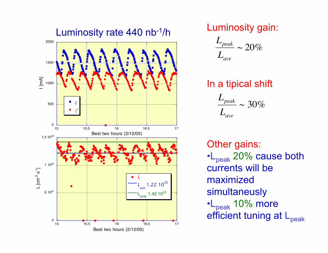
0
500
1000
1500
2000
15 15.5 16 16.5 17
I-
I+
I [m
A]
Best two hours (2/12/05)
0
5 1031
1 1032
1.5 1032
15 15.5 16 16.5 17
20051202.fast
LL
ave 1.22 1032
Lpeak 1.42 1032
L [c
m-2
s-1
]
Best two hours (2/12/05)
Luminosity rate 440 nb-1/h Luminosity gain:
€
Lpeak
Lave~ 20%
In a tipical shift
€
Lpeak
Lave~ 30%
Other gains:•Lpeak 20% cause bothcurrents will bemaximizedsimultaneusly•Lpeak 10% moreefficient tuning at Lpeak
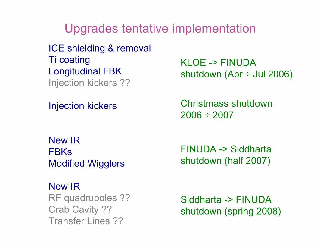
Upgrades tentative implementation
ICE shielding & removalTi coatingLongitudinal FBKInjection kickers ??
Injection kickers
New IRFBKsModified Wigglers
New IRRF quadrupoles ??Crab Cavity ??Transfer Lines ??
KLOE -> FINUDAshutdown (Apr ÷ Jul 2006)
Christmass shutdown2006 ÷ 2007
FINUDA -> Siddhartashutdown (half 2007)
Siddharta -> FINUDAshutdown (spring 2008)

Luminosity projections for finuda 3rd run
Starting from 1.5*1032, 2 fb-1/year
1.95*1032 (2.6 fb-1) by ICE shields & removal + 30%2.73*1032 (3.6 fb-1) by higher positron current +40%3.55*1032 (4.7 fb-1) by new interaction region + 30%4.44*1032 (5.9 fb-1) by feedback upgrades + 25%4.44*1032 (6.7 fb-1) by wigglers linearization5.77*1032 (8.4 fb-1) by crab cavities + 30%6.92*1032 (10. fb-1) by transfer lines upgrade +20%8.99*1032 (12.8 fb-1) by waist modulation (RF quads) +30%
In the projections only the conservative, high likelihood estimatesare considered.

All modifications are worldwide top of the lineaccelerator physics.
All the investments done so far are used as abase for excellent and essential physics
All proposed improvements can be achieved ifresources, man power and machinedevelopment time can be allocated!


![Herman Hesse - Siddharta [serbian]](https://static.fdocuments.net/doc/165x107/577ce7be1a28abf10395b562/herman-hesse-siddharta-serbian.jpg)