GPU assisted light field capture and processing assisted light field capture and processing ......
49
GPU assisted light field capture and processing Attila Barsi Holografika GPU Day, Budapest, 22. 06. 2017.
Transcript of GPU assisted light field capture and processing assisted light field capture and processing ......

GPU assisted
light field capture and processing
Attila Barsi Holografika
GPU Day,
Budapest, 22. 06. 2017.

What is this all about?
Ninjas! Motivation: ninjas are cool, and can
do lots of tricks that we also want to.

Ninja illusions
Motivation: visualize 3D scenes in thin air.

Light field
• Amount of light in every
direction through every point in
space
• Can be described by the 5D
plenoptic function.
• Light field displays aim to
reconstruct the plenotic
function with various
restrictions (e.g. discretization,
RGB instead of radiance, etc.)

What are light field displays?
• Generic sense: – Any collection of (visible) light sources that can
be used to emit light rays with known properties within a time slice, can be considered a light field display.
– Light ray properties can include light ray origin, direction, light color (wavelength), intensity, polarity and phase
– This includes everything from a single LED light source, 2D displays, stereoscopic and autostereoscopic displays to full parallax holographic systems.

What are light field displays?
• Restrictive sense
– The closer the display’s capability is to emit
controlled light in every direction through
every point in space, the closer we are to a
real light field display
• Special cases we are interested in:
– Horizontal parallax only autostereoscopic
display
– Full parallax autostereoscopic display

The HoloVizio System
• Optical modules
– Project light beams to hit the points of a
screen with multiple beams under various
angles of incidence
– The exit angle depends only on the relative
position of the given screen point and the
relevant modules
• Holographic screen
– Direction selective property with angularly
dependent diffusion characteristics
– The screen diffusion angle d is equal to the
angle g between the neighboring modules
• Emission angle geometry determined
– No optical road-blocks like at Fresnel, or
lenticular lenses

The HoloVizio System • FOV
– Controlled FOV determined by the module optics and arrangement
– Wider FOV, more complexity; the freedom given to the viewer is the challenge
– No favorable zone in the FOV, viewers can freely move in the whole FOV area
• Angular resolution / FOD
– Large number of light beams can be emitted from the same small screen pixel area
– The angular resolution determine the FOD
– The smallest feature (voxel) the display can reconstruct is the function of the
angular resolution and the distance from the screen (p = po+ s * tan Φ )
– The achievable resolution is decreasing with the distance from the screen
The HoloVizio System
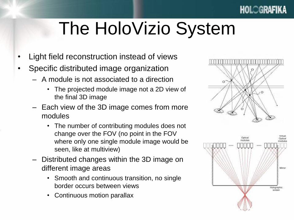
• Light field reconstruction instead of views
• Specific distributed image organization
– A module is not associated to a direction
• The projected module image not a 2D view of
the final 3D image
– Each view of the 3D image comes from more
modules
• The number of contributing modules does not
change over the FOV (no point in the FOV
where only one single module image would be
seen, like at multiview)
– Distributed changes within the 3D image on
different image areas
• Smooth and continuous transition, no single
border occurs between views
• Continuous motion parallax

HoloVizio Displays
• Large-scale HoloVizio Systems – HoloVizio 722RC
• 72”, 34.5 Mpixel, 16:9
• 50-70° FOV, 0.9° Φ
• Input: Gigabit Ethernet
• PC-based render cluster
• LED based projection engines – Better colours
– More uniform image
– Less maintenance

HoloVizio Displays • The full angle HoloVizio monitor
• HoloVizio 80WLT
• 78 Mpixel, 30” (16:10)
• 180 degrees FOV
• Total freedom 3D experience,
no invalid zones,
no repeated views
• 2D equivalent image resolution
1280 x 768 (WXGA)
• LED colors
• Multiple DVI inputs

HoloVizio Displays • The world first glasses-free
3D cinema system:
• HoloVizio C80 – 3,5 m dia Holoscreen (140”)
– No glasses, no optical contradiction
– LED based 3D projection unit
– Exceptional 1500 Cd/m2 brightness
– 40 degrees FOV
– 2D compatible
– Fitting cinema rooms, 3D simulators

“Screenless” HoloVizio display
13
Floating 3D visual reality workstation
Towards mixed reality
- Light and shadow effects
- Simulated touch

Benefits • View with naked eye
– No glasses – No tethers – No tracking – No positioning – No image jumps
• Wide Field Of View • Virtual object position
– Behind screen – In front of screen
• Look behind objects • Multi-user collaboration • 3D movie is more like a
theatrical performance
In short, none of these!
She’s got the
right idea!

Light field capture
• Capture equipment is a collection of light sensors that
sample radiance in a section of 3D space.
• Typically an array of pinhole or plenoptic cameras are
used to capture the scene.
• There are camera systems with both sparse and dense
sampling along the baseline.
• Depending on the characteristics of the display, we need
to adjust the design of the camera system that provides
a capture as close as possible.

Ninja hiding
Motivation: hide or remove image errors (focus, occluders, etc.)

Dense light field capture
• Dense light fields are typically
captured by plenoptic cameras.
• Small baseline
• Microlens array optics
• Integral imaging
• Results in a high number of 2D
images.
• Both horizontal and vertical
parallax are captured.
Raytrix plenoptic camera

Dense light field capture
LF image by Todor Georgiev

Light field refocusing
• With dense light field capture depth of field effects can
be achieved as most required ray for the effect are
captured.
• Both focus and aperture of the final image can be
changed by averaging the captured rays based on the
ray table of the result camera.
• Use the mathematical model of the lens, or ray-trace the
camera optics on the GPU to get the correct camera
rays.
• Ideally suited for GPU, can be precomputed into simple
lookup table.

Light field completion • By Yatziv, Sapiro and Levoy
• Register light field image
• Generate median image from the light
field to find object behind occluder.
• Removes occluders, such as fences,
leaves, thin branches, etc from the final
image.
• Light Field Completion Using Focal
Stack Propagation by Terence Broad is
also a fast and simple approach for the
same task.

Sparse light field capture
• Sparse light fields are captured with
pinhole camera arrays.
• Density depends on camera size.
• Can be horizontal parallax only.
Fraunhofer IIS LF camera Stanford Multi-Camera Array

Light field conversion
• Resamples captured light field into the display’s light
field.
• Display’s light rays are ray traced through the display’s
optics on the GPU to provide the final rays on the
observer line.
• For all display rays we can calculate the cameras that
have the closest eye positions to the ray.
• By projecting the ray’s end into the camera we can
define a sampling position from the camera system.
• We can generate a color for the display ray by
interpolating between the selected camera pixels.

Light field conversion, rendering
• Render from
converter tables,
interpolate two
closest cameras
(GLSL).

Color spaces
• Bayer RGGB, 8 bpp this is what the
camera sees. Final pixel needs
multiple pixels for RGB conversion.
• YCbCr planar , 12-16 bpp, some GigE
cameras provide this. Can be
converted by a 4x4 matrix into RGB.
Usually stored in three separate
texture arrays. Only need to sample a
single value from the 3 color planes.
• RGB, 24 bpp, if this mode is selected,
the conversion is done on the CPU on
the receiver size by the IDS driver.
Bayer filter pattern
on IDS cameras

GPU Bayer demosaic
Based on Morgan McGuire’s work. Utilizing Malvar-He-Cutler
algorithm.

GPU Bayer demosaic
Ninja equipment
Motivation: sometimes you still need lots of hardware…

The HV 48 G LFC camera array • 48 modified IDS cameras.
• 1280*1024 resolution
each.
• 4x10 Gb Ethernet
connection to array.
• Arc camera setup.

System Overview
48x IDS
camera
POE switch
Broadcaster PC
4x10 GigE
Render cluster nodes (9
HW, 27 SW) Render cluster nodes (9
HW, 27 SW) HV1080T Render cluster
nodes (9 HW, 27 SW)
48x IDS
camera 48x IDS
camera 9x40 GigE

Camera broadcaster
• Massively parallel, high throughput broadcaster software.
• Handles 48 IDS Gbit ETH cameras. Each camera is handled on a
different thread. Per camera thread for camera driver and camera
receiver.
• Per cluster node thread for cutting and transmitting camera images.
• Additional threads for synchronization.
• 2*(20+20 HT) core CPU to provide sufficient I/O.
• Overall > 100 CPU threads.
• Had to assign threads to CPU cores to prevent image loss (frame
skip).

Camera broadcasting
• Camera images need to
be broadcasted to
rendering nodes.
• Only broadcast what the
renderer needs. Calculate
based on the converter
lookup tables.

Generating clones
Motivation: replace real cameras with virtual ones

Sparse to dense light field generation
• For high angular resolution displays 48 cameras
are not enough.
• Disparity and depth estimation methods can be
used to enhance the captured light field image.
• Simple disparity estimation can be done in real-
time.
• Consistent depth estimation is more costly and
is used for offline processing.

Disparity estimation
Rectification Disparity
estimation Interpolation LF conversion
• Disparity is the pixel distance between two corresponding points on a rectified stereo
image pair. Camera parameters and disparity determine estimated depth.
• Several algorithms exist for disparity estimation. Most of them are GPU accelerated.
• We have implemented stereo block matching. We are experimenting with various
estimation algorithms. A comprehensive list is available at:
http://vision.middlebury.edu/stereo/eval3/

Disparity on GPU
• Estimate on lower resolution image first, but careful,
resolution reduction in the horizontal also applies to
disparity values.
• Propagate to higher resolution and multiply with the
horizontal change.
• This way in every step you only need to search in small
window around the current disparity, not the whole
disparity range.
• Left to right and right to left disparity can differ, if both
are calculated the precision can be increased.

Rectification
• Based on the calibrated intrinsic and
distortion camera parameters, a pairwise
rectification of camera images is needed.
• Focal length, principal point and distortion
parameters are used to create an inverse
mapping.

Rectification
Image interpolation
• If a single disparity value is calculated,
simply calculate the interpolated image by
translating the original pixel with the
interpolated disparity value.
• Resulting image will contain holes that can
be filled with various image processing
algorithms, e.g. inpainting.

QoE evaluation
• QoE research conducted by Holografika and
using subjective evaluation has shown that
simple disparity generation methods yield
disturbing visual artifacts when the camera’s
captured LF ray density falls below a display
dependent threshold.
• Depth reconstruction algorithms however
generate significantly better results from the
same source LF at higher computation costs.

Multi-view depth estimation
• Estimate depth for segments only. Reduces depth search complexity. Refine
depth estimated for segments. Fuse depth maps from multiple views to
obtain a final result.
• (Full algorithm description has been submitted to Siggraph ASIA, we will only
describe the basics.)
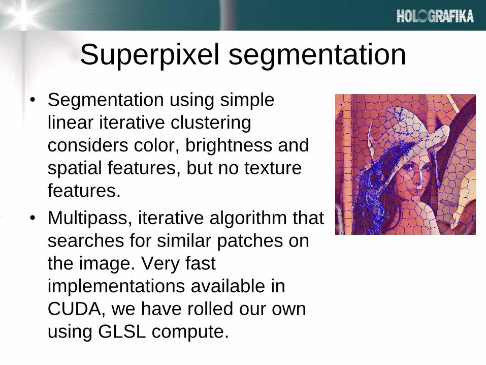
Superpixel segmentation
• Segmentation using simple
linear iterative clustering
considers color, brightness and
spatial features, but no texture
features.
• Multipass, iterative algorithm that
searches for similar patches on
the image. Very fast
implementations available in
CUDA, we have rolled our own
using GLSL compute.

Initial depth estimation
• Uses depth sweep
• Photoconsistency is evaluated as
truncated sum of squared differences.
• Photo-consistency cost values between
the reference and mapped pixels are
weighted based on similarity of the
reference pixels colors to the superpixel
color and are accumulated over the
superpixel area and across the views.

Depth map refinement
• Energy minimization for smoothness and
consistency.
• The smoothness term enforces spatial
smoothness by penalizing inconsistency
between neighbor superpixels of similar
color.
• The consistency term ensures that the
depth maps agree with each other.

Unstructured lumigraph rendering
• The light rays from the input views are appropriately
weighted based on angular similarity and blended to
form the output light rays. Additionally to the angular
similarity, we detect the edges on the reconstructed
depth maps and incorporate this information into the
weighting function in order to attenuate smoothly the
weights of the input rays that lay close to the depth
discontinuities. This is done due to the reasons that
depth estimation errors are mainly located at occlusions
close to depth discontinuities and that pixels along the
objects boundaries usually contain mixed foreground
and background colors.

Conclusions
• Light field capture is hard
• Needs lots of cameras/bandwidth/CPU just to capture
the original images.
• Bandwidth can be reduced by selecting ”what we need”
• Bandwidth can be reduced by transferring ”raw” camera
images
• Bandwidth can be reduced by replacing real cameras
with virtual cameras
• This can wastly increase quality for offline processing.
• If we have the correct depth estimation, we can render
LF images directly, we don’t need to do costly image
interpolation

Contributors
• Aleksandra Chuchvara, Tampere University of
Technology, on multi-view depth estimation.
• Aron Cserkaszky, Holografika, on disparity
estimation and QoE related algorithms
• Gábor Puhr, Holografika, on disparity estimation
related algorithms

Acknowledgement
• ETN-FPI - European Training Network on Full Parallax Imaging
(ETN-FPI, H2020-MSCA-ITN-2015, ref. no. 676401)
• The European Union’s Horizon 2020 research and innovation
program under the Marie Sklodowska-Curie grant agreement No
643072, Network QoE-Net.
• Eureka LiveRay project founded by Hungarian NRDI fund
• As always, the author would like to thank the Computer Graphics
Group @ BME, especially Dr. László Szirmay-Kalos and Dr. László
Szécsi for teaching him GPU programming.

References
• T. Balogh et al.: Holovizio 3D Display System (3DTV-CON) 2007.
• Yatviz, Sapiro, Levoy: Lightfield completion, 2004.
• Bertalmio et al.: Image Inpainting (Siggraph) 2010.
• McGuire: Efficient, High-Quality Bayer Demosaic Filtering on GPUs (Journal of Graphics Tools) 2009.
• Achanta et al: SLIC superpixels compared to state-of-the-art superpixel methods. (IEEE transactions on pattern analysis and machine intelligence) 2012.
• http://vision.middlebury.edu/stereo/
• http://www.robots.ox.ac.uk/~victor/gslicr/
Ninja images taken from:
• http://naruto.wikia.com/wiki/Narutopedia

Question?