GPRS Overview
41
GPRS Overview
-
Upload
priscilla-roman -
Category
Documents
-
view
118 -
download
6
description
GPRS Overview. BTS. Agenda. History. The GPRS network and its new elements. GMM States/Procedures, SM & RR The GPRS Um and A-bis Interface. Protocol layers The GPRS Gb Interface Protocol layers The GPRS Gn/Gi/Gp.... Interfaces EGPRS. History. - PowerPoint PPT Presentation
Transcript of GPRS Overview

GPRS Overview
Slide 2
BTS
Agenda
History. The GPRS network and its new elements.
– GMM States/Procedures, SM & RR The GPRS Um and A-bis Interface.
– Protocol layers The GPRS Gb Interface
– Protocol layers The GPRS Gn/Gi/Gp.... Interfaces EGPRS

Slide 3
History
In 1994, a Special Mobile Group started to think about a High Speed Data upgrade for GSM.
The first step was HSCSD (High Speed Circuit Switched Data).– HSCSD is a circuit-switched extension to GSM.
The next step was GPRS.– GPRS is a packet-switched extension to GSM.

Slide 4
What is HSCSD?
HSCSD (High Speed Circuit Switched Data).– HSCSD invented the principle of timeslot bundling to achieve higher
throughput rates. – The simplest high speed data upgrade for GSM.– Provides GSM users with a bandwidth up to 57.6 Kbps.– Does not require a hardware upgrade within BSS or core network
(NSS), but different MS are needed.
NOTE: Even though HSCSD is easy to implement into the GSM network, hardly any operator have decided to implement it.
– The commercial implementations of HSCSD barely exceed a speed of 38.4 Kbps. – Most common implementation is 14,4 Kbps which only requires one full rate TCH.

Slide 5
What is GPRS?
GPRS (General Packet Radio Service) is a packet oriented data service for IP and X.25 over GSM networks.
Enables packet-switched services on the resources of the already existing GSM network infrastructure
Deploying new channel coding schemes and timeslot bundling, GPRS is capable of providing single user throughput rates of up to 160 kbit/s (in theory).
Provides an “always on” functionality, without continuous consumption of resources.
Requires a major hardware upgrade in the GSM network and it requires new mobile stations
A step toward 3G networks (2.5G).

The GPRS network and it’s new elements.

Slide 7
From GSM to GPRS....
UmMAPISUP
MAPMAPISUP
GSM
AA-bis
BSS
PSTN/ISDN
R
Gi
Gp
Gb Gs
Gf
GrPDN
PrivateBackbone
Gn
Gn
GPRS
Gc
PDN

Slide 8
GPRS interfaces

Slide 9
SGSN (Service GPRS Support Node) Handles:
– PDP contexts for Mobile Stations.– Determines Quality of Service assigned to user.– Routes packets to Mobile Stations.– “Pages” Mobile Stations when data is to be sent.– Handover/cell Change
Stores:– Subscriber data for all Mobile Stations in the location area.– Store not-acknowledged packets in case of a cell change during an ongoing packet
data transfer Security:
– Authentication, by means of identity or equipment check.– P-TMSI is allocated by SGSN.– Ciphering. (Not only in ”Um as in GSM” but all the way down to SGSN).
Charging– Together with the GGSN the SGSN collects CDR's (Call Data Records). Opposed to
the GGSN, the SGSN collects CDR's for the use of the own network resources. These CDR's are forwarded to the Charging Gateway (CG) via the IP-based intra-PLMN backbone
Slide 10
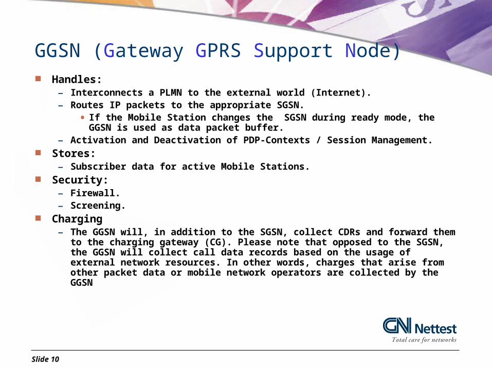
GGSN (Gateway GPRS Support Node) Handles:
– Interconnects a PLMN to the external world (Internet).– Routes IP packets to the appropriate SGSN.
• If the Mobile Station changes the SGSN during ready mode, the GGSN is used as data packet buffer.
– Activation and Deactivation of PDP-Contexts / Session Management. Stores:
– Subscriber data for active Mobile Stations. Security:
– Firewall.– Screening.
Charging– The GGSN will, in addition to the SGSN, collect CDRs and forward them to the
charging gateway (CG). Please note that opposed to the SGSN, the GGSN will collect call data records based on the usage of external network resources. In other words, charges that arise from other packet data or mobile network operators are collected by the GGSN
Slide 11
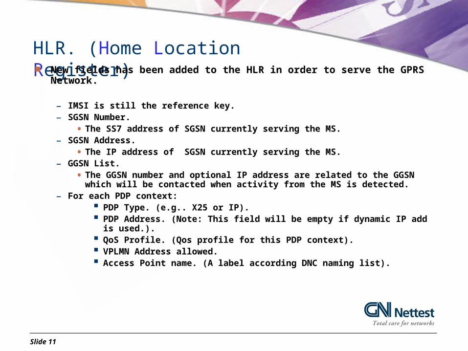
HLR. (Home Location Register) New fields has been added to the HLR in order to serve the GPRS Network.
– IMSI is still the reference key.– SGSN Number.
• The SS7 address of SGSN currently serving the MS.– SGSN Address.
• The IP address of SGSN currently serving the MS.– GGSN List.
• The GGSN number and optional IP address are related to the GGSN which will be contacted when activity from the MS is detected.
– For each PDP context: PDP Type. (e.g.. X25 or IP). PDP Address. (Note: This field will be empty if dynamic IP add is used.). QoS Profile. (Qos profile for this PDP context). VPLMN Address allowed. Access Point name. (A label according DNC naming list).

Slide 12
BSS (Base Station Subsystem)
In GPRS, LA is divided into RA. Each RA contains one or more cells.
LA = Location Area.LAI = MCC+MNC+LACRA = Routing Area (Subset of LA)RAI = LAI+RAPCU = Packet Control Unit.CCU = Channel Codec Unit.
LA 1LA 2
RA 1
RA 3
RA 5
RA 2
RA 4
BTS + CCU
In a RA, the RAI is broadcasted as System Information.
When an MS is crossing an RA border the MS will initiate an RA update procedure.
New elements (CCU , PCU) are added to the BSS in order to support new coding schemes introduced by GPRS.

Slide 13
PCU (Packet Control Unit) Interface the new GPRS core network to the existing GSM BSS.
– Converting packet data coming from the SGSN in so called PCU-frames that have the same format as TRAU-frames. These PCU-frames are transparently routed through the BSC and towards the BTS. The BTS needs to determine the respective coding scheme and other options before processing a PCU-frame.
Takes over all GPRS radio related control functions from the BSC.

Slide 14
The Mobile Station
Three different classes of mobile stations have been defined.
Class A.– The Mobile Station class A supports simultaneous monitoring and
operation of packet-switched and circuit-switched services. Class B.
– The Mobile Station class B supports simultaneous monitoring but not simultaneous operation of circuit-switched and packet-switched services.
Class C.– The Mobile Station class C supports either circuit-switched or packet-
switched monitoring and operation at a given time.
Slide 15
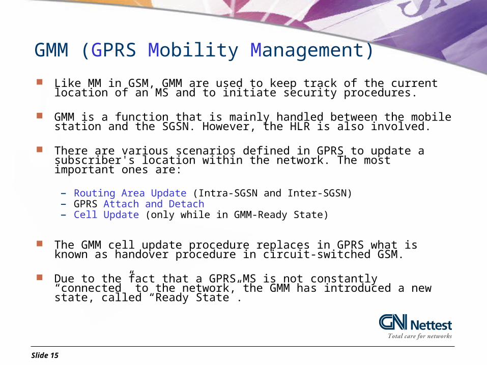
GMM (GPRS Mobility Management)
Like MM in GSM, GMM are used to keep track of the current location of an MS and to initiate security procedures.
GMM is a function that is mainly handled between the mobile station and the SGSN. However, the HLR is also involved.
There are various scenarios defined in GPRS to update a subscriber's location within the network. The most important ones are:
– Routing Area Update (Intra-SGSN and Inter-SGSN)– GPRS Attach and Detach– Cell Update (only while in GMM-Ready State)
The GMM cell update procedure replaces in GPRS what is known as handover procedure in circuit-switched GSM.
Due to the fact that a GPRS MS is not constantly “connected” to the network, the GMM has introduced a new state, called “Ready State”.

Slide 16
GMM States
Idle Mode. (MS off or not attached yet.).– If the MS is on, and is a Class B or Class C MS, the
MS will listen to the network, but not make any updating of where the MS is. It is not possible to page an MS.
Ready Mode. (MS is able to send and receive data).– Cell updating is necessary.– If no activity within the timer (T3314 / Default =
44s) the MS will fall back to a stand-by state.– NOTE: an MS can be forced back to standby mode
due to lack of recourses. Standby Mode. (MS is listening to the Network).
– Only RA update and periodic update is necessary.– It is possible to page the MS.
Idle
Ready
Standby
GPRS Attach
GPRS Detach
Ready Timer expired
Data transfer or reception

Slide 17
GMM Procedures
GPRS Attach/Detach– Made towards the SGSN– The MS must provide its identity (P-TMSI/IMSI) and an indication of which type
of attach that is to be executed (GPRS / combined GPRS/IMSI)– After GPRS attach the MS is in ”Ready” state and MM contexts are established
in the MS and the SGSN. Routing Area Update
– When a GPRS-attached MS detects a new RA (Routing Area)– When the periodic RA update counter has expired
Cell Update– When the MS enters a new cell inside the current RA and the MS is in ”Ready”
state Combined RA/LA update
– Only if option Gs-interface i simplemented
Slide 18
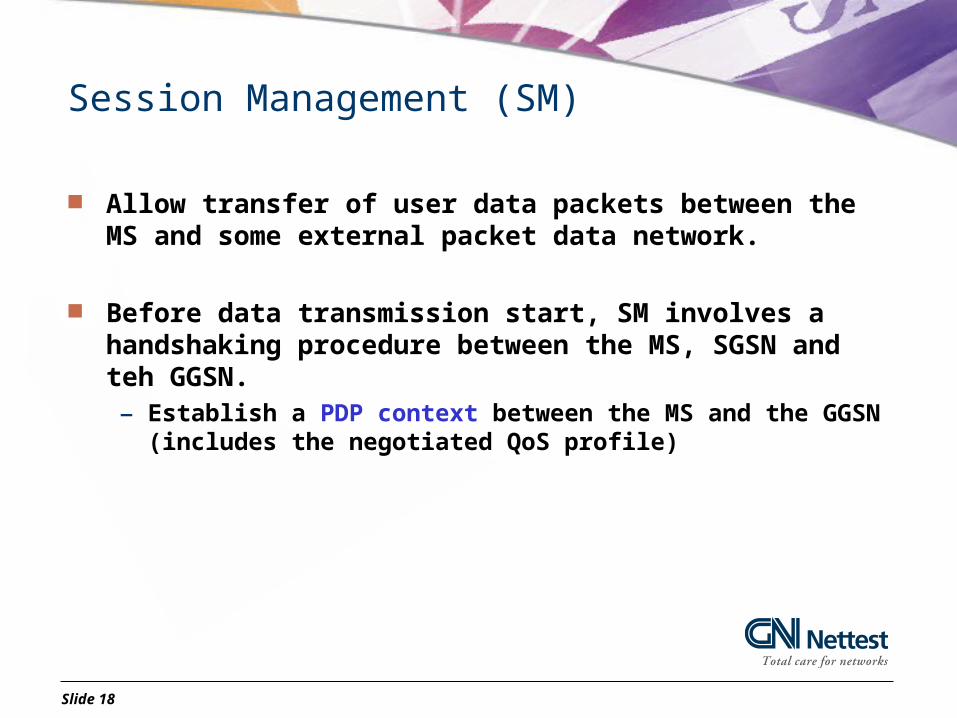
Session Management (SM)
Allow transfer of user data packets between the MS and some external packet data network.
Before data transmission start, SM involves a handshaking procedure between the MS, SGSN and teh GGSN.– Establish a PDP context between the MS and the GGSN (includes the
negotiated QoS profile)

Slide 19
PDP Context Activation
Identifies the transaction parameters of an active session of a GPRS mobile station. – Note that a GPRS mobile station may support multiple simultaneous
sessions and activated PDP-contexts Can be initiated by the network or the MS (in ”Standby” or ”Ready”
state) Cannot be activated before a GMM context exists. (A GPRS mobile
station first needs to register itself towards the SGSN before a PDP context activation procedure can be initiated).
Can be deactivated on request of the MS or the SGSN or the GGSN by means of the PDP context deactivation procedure

Slide 20
Radio Resource (RR) Management Procedures Takes care of the allocation and maintenance of radio communication
paths Paging
– The paging procedure moves the MM state to ”Ready” to allow the SGSN to forward downlink data to the BSS
TBF Establishment/Release– A Temporary Block Flow (TBF) is a physical connection used by two RR
entities to support unidirectional transfer of user data or signalling.– The TBF is an allocated radio resource on one or more Packet Data Channels
(PDCH)– A TBF is temporary and is maintained only for the duration of the data
transfer.

Slide 21
GPRS Protocols
The GPRS Um and A-bis Interface

Slide 23
Um Interface
The RLC protocol, and the MAC Protocol is in charge of all radio related control functions on the air interface.
The LLC Protocol is in charge of transmission between SGSN and the Mobile Station. – Delivery of data units to the higher layer in the correct sequence.
The SNDCP Protocol is in charge of Segmentation and compression of Data.
Physical Layer
MAC
LLC
GMM
RLC
SMIP / X25
SNDCP
GPRS Um protocol stack
= Radio Link Control.
= Medium Access Control.
= Logical Link Control.
= SubNetwork Dependent Convergence .
Slide 24
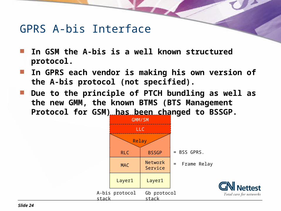
GPRS A-bis Interface
In GSM the A-bis is a well known structured protocol. In GPRS each vendor is making his own version of the A-bis
protocol (not specified). Due to the principle of PTCH bundling as well as the new GMM, the
known BTMS (BTS Management Protocol for GSM) has been changed to BSSGP.
= BSS GPRS.
= Frame Relay
Layer1
NetworkService
Relay
A-bis protocol stack
BSSGP
Layer1
RLC
MAC
LLC
GMM/SM
Gb protocol stack
Slide 25
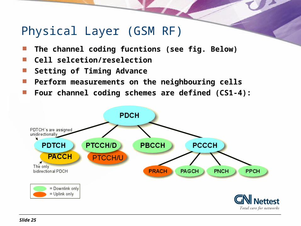
Physical Layer (GSM RF) The channel coding fucntions (see fig. Below) Cell selcetion/reselection Setting of Timing Advance Perform measurements on the neighbouring cells Four channel coding schemes are defined (CS1-4):
Slide 26
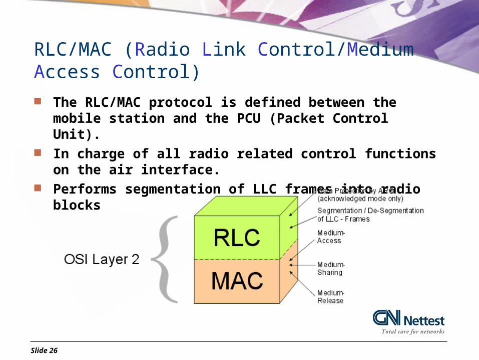
RLC/MAC (Radio Link Control/Medium Access Control) The RLC/MAC protocol is defined between the mobile station and
the PCU (Packet Control Unit). In charge of all radio related control functions on the air interface. Performs segmentation of LLC frames into radio blocks

Slide 27
LLC (Logical Link Control)
LLC provides different types of services to different upper layer applications, namely SNDCP GMM/SM and SMS.
Provides the transport frames
for the data transfer between MS and SGSN
Encapsulation of higher layer protocol data units into LLC data units. (This applies in particular to data units from SNDCP which are tailored to fit into one LLC data unit. )
Delivery of data units to the higher layer in the correct sequence. Ciphering and Deciphering (if enabled)

Slide 28
SNDCP (Sub-Network Dependent Convergence Protocol)
Interface function between the GPRS protocol stack and the different packet data protocols like IP.
The SNDCP is applicable between the MS and the SGSN. – Within the SGSN, there is a relay function from the SNDCP towards the
GPRS Tunneling Protocol (GTP). Segmentation of user data packets (max. 1520 octets)
– Compression of Packet Data (optional) Relies completely on the error recovery and transmission
capabilities of LLC and therefore provides no means for these functions

Slide 29
R
BTS
GPRS Um Interface
SNDPC
LLC
MAC/RLC MAC/RLCInfo H Info H Info H
Segment HFSC Towards the SGSN.
E.g. WWW or E-mail IP
Segmentation and compressing
H = Header.B = Normal Burst, see the GSM recommendation. FSC = Frame Check Sequence.
Towards the PCU
Physical Layer 1.
B B BB
LLC frame Max size 1600 octets.Encryption, error detecting and retransmission.
RLC Block 20 to 50 octets of data
Into normal radio bursts (58bit*8) = 456bit.

Slide 30
Coding Schemes (CS) in GPRS
To achieve higher throughput rates per timeslot than plain GSM, GPRS introduces three new coding schemes. – CS-1. Throughput =< 8kbit/s. Also provided by GSM.
– CS-2. Throughput =< 12kbit/s.
– CS-3. Throughput =< 14.4kbit/s.
– CS-4. Throughput =< 20kbit/s. Due to unpredictable environment of the radio transmission the
distance between MS and the cell impacts the QoS.– The different CS are therefore not always available.
BTS
CS-4
CS-3
CS-2
CS-1

GPRS Gb Interface
L1bis (WAN) L1 (LAN)L1bis (WAN)
MAC
RLC
NS
BSSGP
NS
BSSGP
SNDCP
L2 (PPP)IP
UDP/TCP
GTP
BSS SGSNGb
RELAY
RELAY
LLCLAPG
PLLRFL

Slide 32
Gb protocol layers
BSSGP (Base Station Subsystem GPRS Protocol)– Transparent transfer of signaling and data PDU's between the SGSN and the PCU– Administration of the packet-switched link resources between SGSN and PCU. – Initiation of packet-switched paging for a particular mobile station if requested by
the SGSN.
NS (Network Service) - consists of two sublayers:– The Network Service Control Protocol.
• Provides for virtual connections (NS-VC) between the SGSN and the PCU. These virtual connections need to be administrated by the Network Service protocol
– The Frame Relay Protocol.
• The Network Service is a packet-switched protocol: A single virtual connection may use resources from 0 kbit/s up to the entire bandwidth of the transmission link
– Transports BSSGP PDUs between BSS and SGSN.

Slide 33
GPRS interfaces
Slide 34
Other GPRS interfaces
Gn - GSN backbone network – Private IP network intended for GPRS data/signalling only– Connects the GPRS Support Nodes (GSNs) together within a GPRS PLMN
Gp – inter-PLMN backbone network– PLMN to PLMN connection (i.e. roaming) via Border Gateways (BG)– Packet data Network (public Internet or leased line)
Gi – Interface to external packet data network (IP)
Gs – SGSN to MSC/VLR– Used to perform IMSI attach and GPRS attach simultaneously– Combined paging procedures, where all paging is done form SGSN
Gr – SGSN to HLR– SGSN must contact the HLR whenever a new subscriber enters one of its Routing Areas
Gd – SGSN to SMS– Used if SMS is forwarded over GPRS channels
Gf – SGSN to EIR– Used to check the IMEI number

Slide 35
Gn Interface
L1 (LAN)L1bis (WAN) L1 (LAN)
Frame Relay
BSSGP
SNDCP
L2 (PPP)
IP
UDP/TCP
GTP
L2 (PPP)
IP
UDP/TCP
GTP
IP/X.25
SGSN GGSNGn
RELAY
LLCLAPG

Slide 36
GTP (GPRS Tunnel Protocol)
Allows multi-protocol packets to be tunnelled through the GPRS backbone between GPRS Support Nodes (GSNs).
Responsible for the transmission of both, signaling information and application data.
Based on an IP-protocol stack and uses UDP as transport layer (OSI layer 4)
Also takes care of the transfer of charging information. In that function, GTP is called GTP'

Slide 37
UDP/TCP
TCP (Transmission Control Protocol) – Manages the segmentation of a message or file into smaller packets that
are transmitted over the Internet and received by a TCP layer that reassembles the packets into the original message.
– A connection-oriented protocol, which means that a virtual connection is established between the two peers of a TCP-transaction.
– Usually, TCP is used together with IP.
UDP (User Datagram Protocol )– Offers a limited amount of service compared to TCP. Most importantly::
UDP does not provide segmentation or sequencing functions. The application needs to take of these functions.
– UDP is an alternative to TCP if network applications need to save processing time.

EDGE

Slide 39
EDGE
Is not the third alternative to GPRS and HSCSD but rather describes an upgrade for existing TDMA-standards by applying the modulation scheme 8-PSK
EDGE has been adopted for various standards but will migrate GPRS to EGPRS and HSCSD to ECSD

Slide 40
EDGE
EDGE is mainly concerned with the modulation scheme on the Air-Interface.– Originally, EDGE was the abbreviation for Enhanced Data rates for
GSM Evolution. Nowadays, EDGE is the acronym for Enhanced Data rates for Global Evolution.
EDGE is using frequency modulation scheme 8-PSK in order to increase the Data speed. – Applying 8-PSK-modulation to such a network implies shrinking of the
cell size. – GSM and GPRS are using the same modulation scheme GPSK.
Not only is a new core network required, but also additional BTSs and a new cell structure is needed. – EDGE requires a major hardware upgrade and this is extremely costly
to the operator.

Slide 41
EGPRS (Enhanced GPRS)
Introduction of a new modulation technique – 8PSK, 8 Phase Shift Keying. 8PSK enables air interface bitrates roughly 3 times higher than traditional GMSK (Gaussian Minimum Shift Keying)
However, the major disadvantage of 8-PSK modulation is that it includes amplitude modulation.
Q
I
Start
+90(same bit)
-90(diff bit)
Q
I(1,1,1)
(0,1,1)
(1,0,0)
(1,0,1)
(0,0,1)
(0,0,0)(0,1,0)
(1,1,0)
8PSK: 1 Symbol = 3 bits GMSK: 1 Symbol = 1 bit