GPA 13.8 kv Crane Power Annual PM, Sav 18-21gpa.gaports.com/purchasing/webbids.nsf... · Blower...
23
1 of 23 GPA 13.8 kv Crane Power Annual PM, Sav 18-21 Crane number _____________ Contractor Job # Inspection date: ____________ GPA Work Order # Inspected by: _________________________ Trolley Hour Meter Reading _____________ Gantry Hour Meter Reading Crane Hour Meter Reading _____________ Hoist Hour Meter Reading SAFETY PRECAUTIONS: PRIOR TO SERVICING EQUIPMENT ALL ELECTRICAL AND MECHANICAL ENERGY SOURCES SHALL BE ISOLATED, DE-ENERGIZED, LOCKED OUT, AND TAGGED OUT. EQUIPMENT MAY BE POWERED FROM MULTIPLE SOURCES. PERSONAL PROTECTIVE EQUIPMENT IS REQUIRED TO PERFORM THIS (PM) PREVENTIVE MAINTENANCE PER NFPA 70E GUIDELINES. Tools required: 40 Kcal/cm2 flash suit 20 kv rated gloves Tic (voltage) tracer rated above 15kv Hand Tools 15 kv megger Ductor 10 amp Hi-Pot Secondary injection kit(RMS 9) Blower Shop vacuum Extension cords Generator Cleaning supplies 5kv battery powerd megger TTR Ladder Medium voltage PM Lock Out, Tag Out: All of the items below to be performed prior to starting any of the steps in this PM Ensure Crane is parked in agreement with GPA Crane Operations 912/964-7863 Ensure no persons are on the Crane to be de-energized Set crane stow pins (if possible) Connect 480 volt shore power when available Ensure Proper GPA personnel are notified that you are De-Energizing the circuit(crane)
-
Upload
truongdiep -
Category
Documents
-
view
215 -
download
0
Transcript of GPA 13.8 kv Crane Power Annual PM, Sav 18-21gpa.gaports.com/purchasing/webbids.nsf... · Blower...

1 of 23
GPA 13.8 kv Crane Power Annual PM, Sav 18-21
Crane number _____________ Contractor Job #
Inspection date: ____________ GPA Work Order #
Inspected by: _________________________
Trolley Hour Meter Reading _____________ Gantry Hour Meter Reading
Crane Hour Meter Reading _____________ Hoist Hour Meter Reading
SAFETY PRECAUTIONS: PRIOR TO SERVICING EQUIPMENT ALL ELECTRICAL AND
MECHANICAL ENERGY SOURCES SHALL BE ISOLATED, DE-ENERGIZED, LOCKED OUT, AND
TAGGED OUT. EQUIPMENT MAY BE POWERED FROM MULTIPLE SOURCES. PERSONAL
PROTECTIVE EQUIPMENT IS REQUIRED TO PERFORM THIS (PM) PREVENTIVE
MAINTENANCE PER NFPA 70E GUIDELINES.
Tools required:
40 Kcal/cm2 flash suit
20 kv rated gloves Tic (voltage) tracer rated above 15kv
Hand Tools
15 kv megger Ductor 10 amp Hi-Pot Secondary injection kit(RMS 9)
Blower Shop vacuum Extension cords Generator Cleaning supplies 5kv battery powerd
megger TTR Ladder
Medium voltage PM Lock Out, Tag Out:
All of the items below to be performed prior to starting any of the steps in this PM
Ensure Crane is parked in agreement with GPA Crane Operations
912/964-7863
Ensure no persons are on the Crane to be de-energized
Set crane stow pins (if possible)
Connect 480 volt shore power when available
Ensure Proper GPA personnel are notified that you are De-Energizing the circuit(crane)

2 of 23
Identify the Medium Voltage Circuit breaker that feeds the crane to be serviced
Turn Off Medium voltage Circuit Breaker following NFPA 70E guidelines
Rack out the Medium Voltage Circuit breaker following NFPA 70E guidelines
Lock Out Medium voltage Circuit Breaker following NFPA 70E guidelines
Ground Out Medium voltage Circuit Breaker following NFPA 70E guidelines, then Hang
"Grounds Applied" sign on the De-Energized compartment door
Procure the key for the Medium Voltage Compartments from the Switchgear cabinet
Medium voltage circuit breaker Inspection Task List:
Using the breaker cart remove the breaker from the cell, and move to the test area in the
switchgear room.
Ground the breaker to the switchgear room ground.
Record the "Breaker Nameplate Information" on the test sheet
Inspect the Breaker per the manufacturer’s recommendations, and NETA guidelines.
Record the findings on the test sheet.
Clean the circuit breaker
Lubricate the circuit breaker per the manufacturers recommendations
Inspect and clean primary disconnect fingers, secondary disconnects, and grounding
disconnect.
Verify proper operation of auxiliary contacts.
Inspect, clean, and lubricate racking mechanism adjustments per manufacturer’s
recommendations. Check for dirt, binding, misalignment, loose connections, wear, or
corrosion.
Inspect all control relays, switches, fuses, wiring, terminal discoloration, corrosion, and
wear. Clean contacts and wiring termination’s as needed. Tighten all connections per
manufacturer’s recommendations
Test the Breaker per the manufacturer’s recommendations, and NETA guidelines. Record
the measurements on the test sheet.

3 of 23
Remove the ground wire between the breaker and the switchgear room ground.
SWITCHGEAR CUBICLE: IF CELL IS ENERGIZED USE EXTREME
CAUTION, AND FOLLOW NFPA 70E GUIDELINES FOR PPE.
Vacuum and clean circuit breaker cubicle thoroughly. Inspect all switches, fuses, wiring,
and terminal blocks. Check all lugs for tight connection.
Inspect, clean and lubricate cubicle racking mechanism. Check for dirt, binding,
misalignment, loose connections, wear or corrosion.
Inspect cubicle primary disconnect, secondary disconnect, and grounding disconnect. If
cubicle is de-energized, clean disconnects and apply a thin film of conducting grease.
Verify proper operation of primary disconnect shutter assembly.
If the breaker passes all tests, install the breaker back into its cell (Test position)
Connect the secondary disconnect plug.
Verify operation of all indicating lights.
Verify operation of Open/Close switch.
Verify operation of all metering equipment.
Open & Close breaker utilizing the Multilin SR750 feeder Management Relay.

4 of 23
MEGGER ALL CRANE FEEDERS FROM GEAR TO CRANE DISCONNECT at
15 kvDC. Record readings below
o Note; Megging one phase while the other 2 phases are ungrounded will meg the
whole system from the MV Breaker cubicle to the transformer. If the readings are
low, then the circuit will have to be isolated between components/phases.
o Caution: After megging it will take a long period of time for
the cables to discharge. Use Caution prior to regrounding the
system.
Megger readings in Megohms for complete system OPTIONAL: Megging individual feeds, crane MV switch must be opened, and fuses on CPT’s in back of switch must be removed:
Megger readings in Megohms for A phase Megger readings in Megohms for B phase Megger readings in Megohms for C phase

5 of 23
Georgia Ports Medium Voltage Circuit Breaker Electrical Test Report Breaker Nameplate Information Breaker ID , Circuit ID:
Manufacturer __________, Breaker Type: , Serial #:
Current Rating __________ Voltage Rating: Trip Voltage: Close Voltage:
Operation Counter:
Breaker Inspection Information Enclosure: , Safety Interlocks: , Primary Disconnects:
Mechanism: , Secondary Disconnects: , Electrical Operation:
Grounding Device: , Breaker Lubrication:
Breaker Test Information
Contact Wear Indicator A B C
Contact Wipe/Gap A B C
Ductor Test (all values in μΩ) A B C
Insulation Integrity (Breaker Closed) Megohms at 15k VDC
AG _________ BG _________ CG __________
Vacuum Integrity (Breaker Open) at 50k VDC:
A B C
Cable insulation Integrity, from cell to MV disconnect on Crane, Megohms at 15k VDC
AG ______ BG______ CG______
AB______ AC_______ BC______
Comments/Discrepancies:

6 of 23
Medium voltage, switch Task List:
Obtain the locks to the Medium Voltage Switch Compartment from the Switchgear
cabinet
Verify that the Crane is De-Energized
Unlock the padlocks on the Medium Voltage Switch compartment
Lubricate the padlock(s)
Open the switch compartment doors, and remove necessary covers
Check the switch compartment for power following NFPA 70E guidelines
Ground Out the switch following NFPA 70E guidelines
Record the "Switch Nameplate Information" on the test sheet.
Remove the Fuses from the switch, and place in a safe area laying horizontal.
Remove, Clean, Inspect, and test CPT and/or PT fuses if applicable.
Clean, Inspect, and test the fuses. Record the test data on the test sheet.
Clean the switch components, and compartment.
Inspect the Switch per the manufacturer’s recommendations, and NETA guidelines.
Record the findings on the test sheet.
Lubricate the switch per the manufacturers guidelines
Test the switch per the manufacturer’s recommendations, and NETA guidelines.
Record the measurements on the test sheet.
Lubricate the fuse ends, and clips.
Reinstall the fuses.
Remove grounds from switch compartment per NFPA 70E guidelines
Install Switch compartment doors and covers
Install Switch compartment lock(s)
Close the switch, and verify that the contacts have proper penetration

7 of 23
Georgia Ports Medium Voltage Switch Inspection/Test Sheet Switch Nameplate Information Manufacturer __________, Serial #:
Voltage Rating: Current Rating __________
Switch Inspection Information Enclosure: , Mechnical Operation: Contact Alignment:
Contact Penetration: Arcing Blades: Safety Interlocks: ,
Heaters: Fuses: Fuse Type/Size:
Grounding Device: , Lubrication:
Switch Test Information Ductor Test, All Values in Microhms
Through Rotary Switch A B C
Rotary switch to Fuse A B C
Lineside Fuse Clip A B C
Loadside Fuse Clip A B C
Fuses A B C
Comments/Discrepancies:
8 of 23
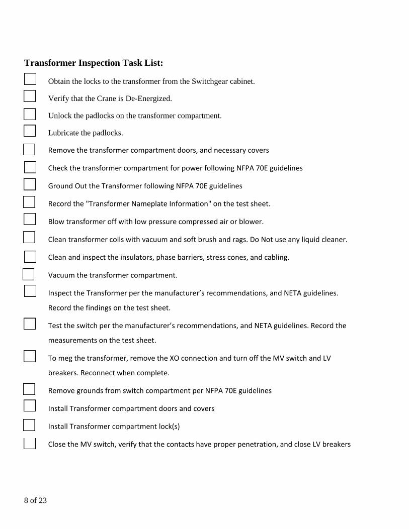
Transformer Inspection Task List:
Obtain the locks to the transformer from the Switchgear cabinet.
Verify that the Crane is De-Energized.
Unlock the padlocks on the transformer compartment.
Lubricate the padlocks.
Remove the transformer compartment doors, and necessary covers
Check the transformer compartment for power following NFPA 70E guidelines
Ground Out the Transformer following NFPA 70E guidelines
Record the "Transformer Nameplate Information" on the test sheet.
Blow transformer off with low pressure compressed air or blower.
Clean transformer coils with vacuum and soft brush and rags. Do Not use any liquid cleaner.
Clean and inspect the insulators, phase barriers, stress cones, and cabling.
Vacuum the transformer compartment.
Inspect the Transformer per the manufacturer’s recommendations, and NETA guidelines.
Record the findings on the test sheet.
Test the switch per the manufacturer’s recommendations, and NETA guidelines. Record the
measurements on the test sheet.
To meg the transformer, remove the XO connection and turn off the MV switch and LV
breakers. Reconnect when complete.
Remove grounds from switch compartment per NFPA 70E guidelines
Install Transformer compartment doors and covers
Install Transformer compartment lock(s)
Close the MV switch, verify that the contacts have proper penetration, and close LV breakers

9 of 23
Dry Type Transformer Inspection/Test Sheet Transformer Nameplate Information Manufacturer __________, Serial #:
Voltage Rating: Current Rating __________ kVA:
Voltage: Primary Secondary Tap
Connection: Primary Secondary Impedance
HV Connections: LV Connections: Tap Connections:
Bus insulator supports: Door Filters: Forced Air Cooling:
Grounding: As Found Condition: As Left Condition:
Transformer Test Information TTR Measured Ratio
Voltage Tap H1/H2 H2/H3 H1/H3 Calculated ratio
13,800: 480/277
13,800: 575/333
Megger Test:
Primary to Ground at 5000 Volts: Megohms, open MV switch, remove fuses
Primary to 480 volt Secondary at 1000 Volts: Megohms
Primary to 575 volt Secondary at 1000 Volts: Megohms
480 volt Secondary to Ground at 1000 Volts: Megohms, Open HCB and
TCB, and remove XO1.
575 volt Secondary to Ground at 1000 Volts: Megohms, Open XCB2, and
remove XO2.
REATTACH XO1 & XO2
Transformer Ground Resistor: Test resistance through resistor to crane ground. Ohms
Comments/Discrepancies:
10 of 23
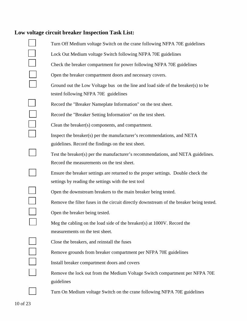
Low voltage circuit breaker Inspection Task List:
Turn Off Medium voltage Switch on the crane following NFPA 70E guidelines
Lock Out Medium voltage Switch following NFPA 70E guidelines
Check the breaker compartment for power following NFPA 70E guidelines
Open the breaker compartment doors and necessary covers.
Ground out the Low Voltage bus on the line and load side of the breaker(s) to be
tested following NFPA 70E guidelines
Record the "Breaker Nameplate Information" on the test sheet.
Record the "Breaker Setting Information" on the test sheet.
Clean the breaker(s) components, and compartment.
Inspect the breaker(s) per the manufacturer’s recommendations, and NETA
guidelines. Record the findings on the test sheet.
Test the breaker(s) per the manufacturer’s recommendations, and NETA guidelines.
Record the measurements on the test sheet.
Ensure the breaker settings are returned to the proper settings. Double check the
settings by reading the settings with the test tool
Open the downstream breakers to the main breaker being tested.
Remove the filter fuses in the circuit directly downstream of the breaker being tested.
Open the breaker being tested.
Meg the cabling on the load side of the breaker(s) at 1000V. Record the
measurements on the test sheet.
Close the breakers, and reinstall the fuses
Remove grounds from breaker compartment per NFPA 70E guidelines
Install breaker compartment doors and covers
Remove the lock out from the Medium Voltage Switch compartment per NFPA 70E
guidelines
Turn On Medium voltage Switch on the crane following NFPA 70E guidelines

11 of 23
Georgia Ports Low Voltage Circuit Breaker Electrical Test Report
Breakers; HCB, TCB, XCB2, H/GDSW, T/BDSW, and MPCB to be tested. Breaker Nameplate Information Breaker ID HCB , Crane # Circuit ID:
Manufacturer __________, Breaker Type: , Serial #:
Trip Unit type Series Static TherMag IC
Breaker Setting Information Pick up Delay
Frame Size Long Delay
CT Rating Short Delay
CT Tap Ground Fault
Plug Rating Instantaneous
Test Setting Test Current Curve/Sec A Phase B Phase C Phase
Long Delay
Short Delay
Gnd. Fault
Instantaneous
Ductor Test (all values in μΩ) A B C
Cable insulation Integrity from load side to H/GDSW. Open both breakers, and remove fuses LPPA.
Megohms at 1000 VDC
AG ______ BG______ CG______
AB______ AC_______ BC______
Connections
Comments/Discrepancies:
12 of 23
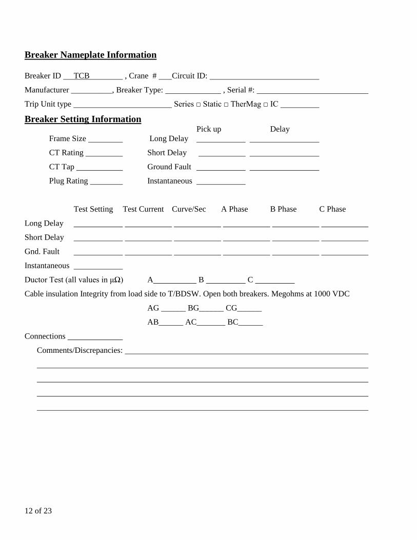
Breaker Nameplate Information Breaker ID TCB , Crane # Circuit ID:
Manufacturer __________, Breaker Type: , Serial #:
Trip Unit type Series Static TherMag IC
Breaker Setting Information Pick up Delay
Frame Size Long Delay
CT Rating Short Delay
CT Tap Ground Fault
Plug Rating Instantaneous
Test Setting Test Current Curve/Sec A Phase B Phase C Phase
Long Delay
Short Delay
Gnd. Fault
Instantaneous
Ductor Test (all values in μΩ) A B C
Cable insulation Integrity from load side to T/BDSW. Open both breakers. Megohms at 1000 VDC
AG ______ BG______ CG______
AB______ AC_______ BC______
Connections
Comments/Discrepancies:
13 of 23
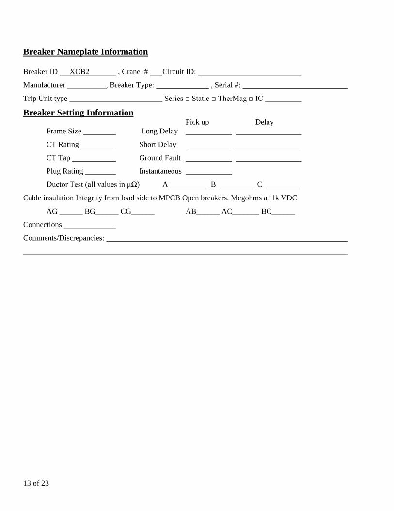
Breaker Nameplate Information Breaker ID XCB2 , Crane # Circuit ID:
Manufacturer __________, Breaker Type: , Serial #:
Trip Unit type Series Static TherMag IC
Breaker Setting Information Pick up Delay
Frame Size Long Delay
CT Rating Short Delay
CT Tap Ground Fault
Plug Rating Instantaneous
Ductor Test (all values in μΩ) A B C
Cable insulation Integrity from load side to MPCB Open breakers. Megohms at 1k VDC
AG ______ BG______ CG______ AB______ AC_______ BC______
Connections
Comments/Discrepancies:

14 of 23
Breaker Nameplate Information Breaker ID H/GDSW , Crane # Circuit ID:
Manufacturer __________, Breaker Type: , Serial #:
Trip Unit type Series Static TherMag IC
Breaker Setting Information
Frame Size Plug Rating Connections
Ductor Test (all values in μΩ) A B C
Comments/Discrepancies:
Breaker Nameplate Information Breaker ID T/BDSW , Crane # Circuit ID:
Manufacturer __________, Breaker Type: , Serial #:
Trip Unit type Series Static TherMag IC
Breaker Setting Information
Frame Size Plug Rating Connections
Ductor Test (all values in μΩ) A B C
Comments/Discrepancies:
Breaker Nameplate Information Breaker ID MPCB , Crane # Circuit ID:
Manufacturer __________, Breaker Type: , Serial #:
Trip Unit type Series Static TherMag IC
Breaker Setting Information
Frame Size Plug Rating Connections
Ductor Test (all values in μΩ) A B C
Comments/Discrepancies:
15 of 23
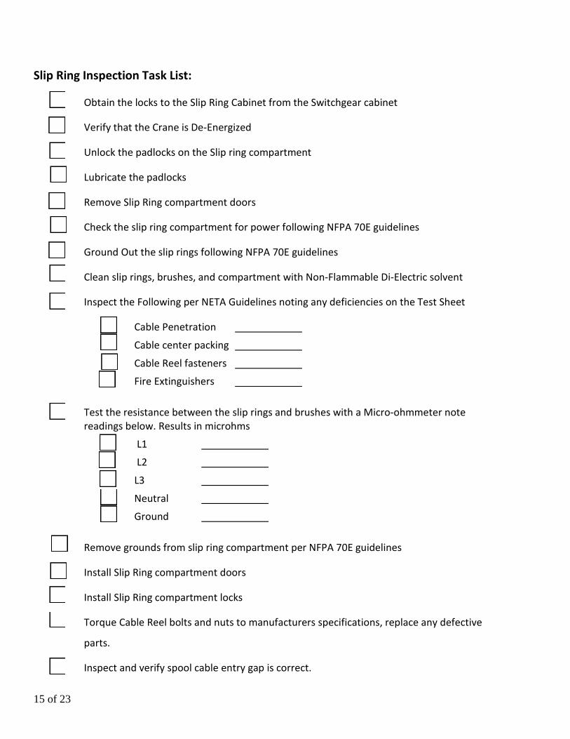
Slip Ring Inspection Task List:
Obtain the locks to the Slip Ring Cabinet from the Switchgear cabinet
Verify that the Crane is De-Energized
Unlock the padlocks on the Slip ring compartment
Lubricate the padlocks
Remove Slip Ring compartment doors
Check the slip ring compartment for power following NFPA 70E guidelines
Ground Out the slip rings following NFPA 70E guidelines
Clean slip rings, brushes, and compartment with Non-Flammable Di-Electric solvent
Inspect the Following per NETA Guidelines noting any deficiencies on the Test Sheet
Cable Penetration Cable center packing Cable Reel fasteners Fire Extinguishers
Test the resistance between the slip rings and brushes with a Micro-ohmmeter note
readings below. Results in microhms L1 L2 L3 Neutral Ground
Remove grounds from slip ring compartment per NFPA 70E guidelines
Install Slip Ring compartment doors
Install Slip Ring compartment locks
Torque Cable Reel bolts and nuts to manufacturers specifications, replace any defective
parts.
Inspect and verify spool cable entry gap is correct.
16 of 23
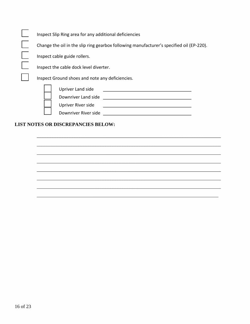
Inspect Slip Ring area for any additional deficiencies
Change the oil in the slip ring gearbox following manufacturer’s specified oil (EP-220).
Inspect cable guide rollers.
Inspect the cable dock level diverter.
Inspect Ground shoes and note any deficiencies.
Upriver Land side Downriver Land side Upriver River side Downriver River side
LIST NOTES OR DISCREPANCIES BELOW:
___________________________________________________________________________
___________________________________________________________________________
___________________________________________________________________________
___________________________________________________________________________
___________________________________________________________________________
___________________________________________________________________________
___________________________________________________________________________
__________________________________________________________________________

17 of 23
Spreader Slip Ring Inspection Task List:
Ensure Crane is parked in agreement with GPA Crane Operations
Set crane stow pins (if possible)
Identify the Circuit Breaker(s) that feed the Spreader Slip Ring
Turn Off the Circuit Breaker(s) following NFPA 70E guidelines
Lock Out the Circuit Breaker(s) following NFPA 70E guidelines
Remove Spreader Slip Ring cover
Verify that the Spreader Slip Ring is De-Energized
Clean slip rings, brushes, and compartment with LP air(canned preferably) and dry rags
where possible (DO NOT USE SOLVENTS OF ANYKIND)
Inspect the Following per NETA Guidelines noting any deficiencies on the Test Sheet
Check Spreader Slip Ring Motor Connections Ensure Spreader Slip Ring Gearbox oil is at correct level Ensure all associated mechanical and electrical fasteners on Spreader Slip Ring
are in place and in functional condition Check Spreader Slip Ring collector housing condition Check condition of all rubber seals Check Spreader Slip Ring wire condition and wire connections Check for water intrusion in slip ring compartment & motor connections Check condition of kit plug Ensure Brake Lens cover is secure Check Encoder connections Check all fasteners on Motor, Pre-Reducer and Gearbox
18 of 23
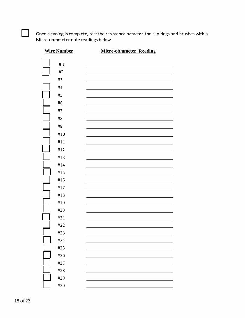
Once cleaning is complete, test the resistance between the slip rings and brushes with a Micro-ohmmeter note readings below
Wire Number Micro-ohmmeter Reading # 1 #2 #3 #4 #5 #6 #7 #8 #9 #10 #11 #12 #13 #14 #15 #16 #17 #18 #19 #20 #21 #22 #23 #24 #25 #26 #27 #28 #29 #30

19 of 23
Install Spreader Slip Ring collector housing, and any removed covers
Inspect Spreader Slip Ring area for any additional deficiencies
Turn ON the Circuit Breaker(s) that feed the Spreader Slip Ring
Inspect Spreader Slip Ring area after Powering up to ensure there are no issues
Test operate Spreader Bar for proper function
LS/WS Flippers
Extend Spreader (20, 40, & 45)
Retract Spreader (20, 40, & 45)
Hoist Raise
Hoist Lower
Pins Engage
Pins Dis-engage
Return Crane to normal ops
NETA: International Electrical Testing Association Inc.
NFPA 70E: National Fire Protection Association Standard for Electrical Safety in the Workplace
LIST NOTES OR DISCREPANCIES BELOW: ____________________________________________________________________________________
____________________________________________________________________________________
____________________________________________________________________________________
____________________________________________________________________________________
____________________________________________________________________________________

20 of 23
Gantry Cable Reel Drive Task List:
Ensure crane is parked in accordance with GPA Crane Operations.
Ensure no person(s) are on the crane to be de-energized.
Set crane stow pins. (If possible)
Check the compartment for power following NFPA 70E guidelines.
Open the compartment doors and necessary covers.
Check connections to all input and output modules.
Check connections to control reset button.
Verify control reset light(s) are functioning properly.
Check connection to drive selection switch.
Check connection to jog up and jog down buttons.
Inspect the breaker(s) per the manufacturer’s recommendations; ensure the breaker settings
are returned to the proper settings.
GCR Drive contactor #1; visually inspect for hotspots and connection point(s) are tight.
GCR Drive contactor #2; visually inspect for hotspots and connection point(s) are tight.
GCR brake #1 relay; visually inspect for hotspots and connection point(s) are tight.
GCR brake #2 relay; visually inspect for hotspots and connection point(s) are tight.
Remove the 30a filter fuses, visually inspect for hotspots and ensure all connections are
tight.
CRfltr (Filter); remove power and read across L1-L2-L3 and check for proper function.
Open the 30a Cable Reel #1 circuit breaker for inspection; visually inspect for hotspots and
loose connections.
Open the 30a Cable Reel #2 circuit breaker for inspection; visually inspect for hotspots
and loose connections.
Close the breakers and reinstall the fuses.
21 of 23
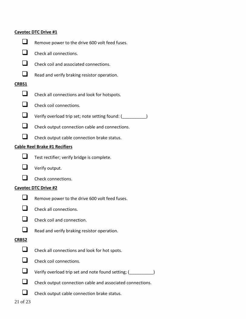
Cavotec DTC Drive #1
Remove power to the drive 600 volt feed fuses.
Check all connections.
Check coil and associated connections.
Read and verify braking resistor operation.
CRBS1
Check all connections and look for hotspots.
Check coil connections.
Verify overload trip set; note setting found: (__________)
Check output connection cable and connections.
Check output cable connection brake status.
Cable Reel Brake #1 Recifiers
Test rectifier; verify bridge is complete.
Verify output.
Check connections.
Cavotec DTC Drive #2
Remove power to the drive 600 volt feed fuses.
Check all connections.
Check coil and connection.
Read and verify braking resistor operation.
CRBS2
Check all connections and look for hot spots.
Check coil connections.
Verify overload trip set and note found setting; (__________)
Check output connection cable and associated connections.
Check output cable connection brake status.
22 of 23
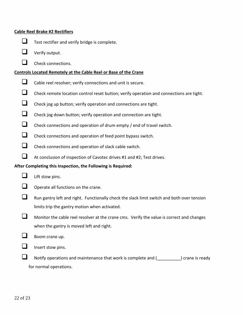
Cable Reel Brake #2 Rectifiers
Test rectifier and verify bridge is complete.
Verify output.
Check connections.
Controls Located Remotely at the Cable Reel or Base of the Crane
Cable reel resolver; verify connections and unit is secure.
Check remote location control reset button; verify operation and connections are tight.
Check jog up button; verify operation and connections are tight.
Check jog down button; verify operation and connection are tight.
Check connections and operation of drum empty / end of travel switch.
Check connections and operation of feed point bypass switch.
Check connections and operation of slack cable switch.
At conclusion of inspection of Cavotec drives #1 and #2; Test drives.
After Completing this Inspection, the Following is Required:
Lift stow pins.
Operate all functions on the crane.
Run gantry left and right. Functionally check the slack limit switch and both over tension
limits trip the gantry motion when activated.
Monitor the cable reel resolver at the crane cms. Verify the value is correct and changes
when the gantry is moved left and right.
Boom crane up.
Insert stow pins.
Notify operations and maintenance that work is complete and (__________) crane is ready
for normal operations.
23 of 23
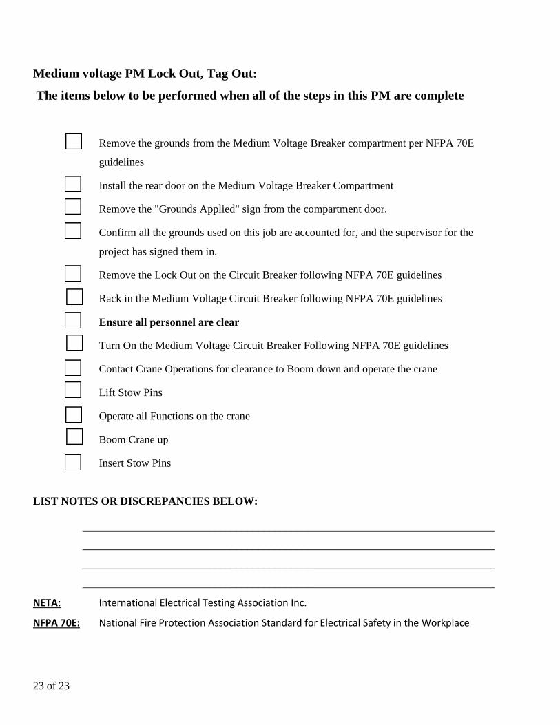
Medium voltage PM Lock Out, Tag Out:
The items below to be performed when all of the steps in this PM are complete
Remove the grounds from the Medium Voltage Breaker compartment per NFPA 70E
guidelines
Install the rear door on the Medium Voltage Breaker Compartment
Remove the "Grounds Applied" sign from the compartment door.
Confirm all the grounds used on this job are accounted for, and the supervisor for the
project has signed them in.
Remove the Lock Out on the Circuit Breaker following NFPA 70E guidelines
Rack in the Medium Voltage Circuit Breaker following NFPA 70E guidelines
Ensure all personnel are clear
Turn On the Medium Voltage Circuit Breaker Following NFPA 70E guidelines
Contact Crane Operations for clearance to Boom down and operate the crane
Lift Stow Pins
Operate all Functions on the crane
Boom Crane up
Insert Stow Pins
LIST NOTES OR DISCREPANCIES BELOW:
___________________________________________________________________________
___________________________________________________________________________
___________________________________________________________________________
___________________________________________________________________________
NETA: International Electrical Testing Association Inc.
NFPA 70E: National Fire Protection Association Standard for Electrical Safety in the Workplace