GLI Pro-P3 PH-OrP Transmitter Controller Operating Manual
70
Rev. 1-202 PRO-series Model P3 pH/ORP Transmitter 1 OPERATING MANUAL PRO-series Model P3 pH/ORP Transmitter (for pH and ORP measurement)
-
Upload
daniel-andres-silva-alvarado -
Category
Documents
-
view
63 -
download
4
description
Manuales PH y ORP
Transcript of GLI Pro-P3 PH-OrP Transmitter Controller Operating Manual

Rev. 1-202 PRO-series Model P3 pH/ORP Transmitter1
OPERATING MANUAL
PRO-series Model P3pH/ORP Transmitter
(for pH and ORP measurement)

PRO-series Model P3 pH/ORP Transmitter Rev. 1-2022
This operating manual and other GLI operating manualsare available on GLI’s web site at gliint.com when viewedusing Adobe’s free Acrobat reader. To get this reader, linkto Adobe through GLI’s web site or visit Adobe’s web siteat adobe.com.
WARRANTY
GLI International, Inc. warrants the PRO-series Model P3 to be free from defectsin material or workmanship for a period of 2 years (24 months) from the date ofshipment of this product from our facility. A warranty claim will not be honored ifdefects are not reported within the warranty period, or if GLI International deter-mines that defects or damages are due to normal wear, misapplication, lack ofmaintenance, abuse, improper installation, alteration, or abnormal conditions.GLI International’s obligation under this warranty shall be limited to, at its option,replacement or repair of this product. The product must be returned to GLI Inter-national, freight prepaid, for examination. The product must be thoroughlycleaned and any process chemicals removed before it will be accepted for re-placement or repair. GLI International’s liability shall not exceed the cost of theproduct. Under no circumstances will GLI International be liable for any inciden-tal or consequential damages, whether to person or property. GLI Internationalwill not be liable for any other loss, damage or expense of any kind, includingloss of profits, resulting from the installation, use, or inability to use this product.

Rev. 1-202 PRO-series Model P3 pH/ORP Transmitter3
Declaration of Conformityaccording to ISO/IEC Guide 22 and EN 45014
Manufacturer’s Name: GLI International, Inc.
Manufacturer’s Address: 9020 West Dean RoadP.O. Box 245022Milwaukee, Wisconsin 53224, USA
declares that the products:
Product Names: PRO-series pH/ORP TransmitterPRO-series Dissolved Oxygen TransmitterPRO-series Electrodeless Conductivity TransmitterPRO-series Contacting Conductivity TransmitterPRO-series Flow Transmitter
Model Numbers: PRO-P3xxx, PRO-D3xxx, PRO-E3xxx, PRO-C3xxx, PRO-F3xxx
conforms to the following Product Specifications:
EMC: EN 50081-2 : 1993Generic Emission Standard (Industrial Environment)
EN 55011 : 1998 / CISPR 11 : 1999 Group 1, Class A
EN 61000-6-2 : 1999Generic Immunity Standard (Industrial Environment)
EN 61000-4-2 : 1995 - ESD Immunity 4 kV CD, 8kV AD
EN 61000-4-3 : 1997 - Radiated Immunity 10 V/m, 80% AM (1 kHz)
EN 61000-4-4 : 1995 - EFT/B Immunity 1.0 kV Signal & Power Lines
EN 61000-4-6 : 1996 - Conducted Immunity 10 V, 80% AM (1 kHz)
Supplementary Information:
The products herewith comply with the requirements of the following directives and carry the CE markingaccordingly:
EMC Directive 89/336/EEC
Products were tested in typical configurations. Specific test configurations and results are published inL.S. Compliance’s Test Report Numbers: 301140, 301222, 301256 and EMC Testing Wisconsin’s TestReport Number 00340.
These devices comply with Part 15 of the FCC Rules. Operation is subject to the following two conditions:(1) this device may not cause harmful interference, and (2) this device must accept any interference re-ceived, including interference that may cause undesired operation.
These devices comply with U.S. UL Standard 1604 (USL) and Canadian National Standard C22.2 No. 213-M1987 (CNL). All devices are UL Listed (Control Number 9NX6) and hold a Class I, Division 2, Groups A,B, C, and D Hazardous Locations rating.
For Compliance Information ONLY, contact:
Product Regulations ManagerGLI International9020 West Dean RoadMilwaukee, Wisconsin 53224, USA

PRO-series Model P3 pH/ORP Transmitter Rev. 1-2024
IMPORTANT SAFETY INFORMATION
Please read and observe the following:
• The transmitter can be located in a Class 1, Division 2, Group A, B, C or D hazardous area.
• Since the transmitter is powered by only low DC voltage, it is completely safe to handle.
• Install the transmitter in accordance with relevant local codes and instructions contained in thisoperating manual. Also, note and comply with the transmitter’s technical specifications and ratings.
• Whenever it appears that transmitter safety is questionable, disable the transmitter to ensure againstany unintended operation. For example, an unsafe condition is likely when:
1) The transmitter appears visibly damaged.2) The transmitter fails to operate properly or provide the intended measurements.3) The transmitter has been stored for long periods at temperatures above 158°F (70°C).
• Only qualified personnel should perform wiring or repairs, and only when the transmitter is not powered.
HELPFUL IDENTIFIERS
In addition to information on installation and operation, this instruction manual may containWARNINGS pertaining to user safety, CAUTIONS regarding possible instrument malfunction,and NOTES on important, useful operating guidelines.
WARNING:
A WARNING LOOKS LIKE THIS. IT WARNS YOU OF THEPOTENTIAL FOR PERSONAL INJURY.
CAUTION:
A CAUTION LOOKS LIKE THIS. IT ALERTS YOU TO POSSIBLEINSTRUMENT MALFUNCTION OR DAMAGE.
� NOTE: A note looks like this. It alerts you to importantoperating information.

Rev. 1-202 5
CONDENSED OPERATING INSTRUCTIONS
This manual contains details for all operating aspects of the instrument. The following con-densed instructions are provided to assist you in getting the instrument started up andoperating as quickly as possible. These condensed instructions only pertain to basic pHmeasurement operation using a GLI Differential pH sensor. To measure ORP, or use aconventional combination electrode or specific features of the instrument, refer to the appro-priate sections in this manual for instructions.
A. CONNECTING SENSOR/CONFIGURING SENSOR TYPE AND TEMPERATURE ELEMENT
1. After properly mounting the transmitter (PART TWO, Section 2), connect the GLIDifferential Technique pH sensor, matching wire colors to terminals as indicated:
Sensor Wire Colors Connect to TB2White Terminal 1- - - - Terminal 2 (unused)
Inner Shield and Black Terminal 3Yellow Terminal 4Green Terminal 5- - - - Terminal 6 (unused)Red Terminal 7
Outer Shield (see Note) Earth Ground
2. The transmitter is factory-set for use with a Guse another type of pH sensor or an ORP sensee PART THREE, Section 3.2, subheading “S
3. The transmitter is factory-set for automatic teohm (NTC300) temperature element built into6006P4-2000 pure water pH sensor system sensor with a different temperature element, ocompensation, change the temperature elemeSection 3.2, subheading “Select TEMP ELEME
B. CONNECTING DC POWER
Refer to PART TWO, Section 3.2, 3.3, 3.4, or 3.5 t
C. CONFIGURING BUFFER TYPE/CALIBRATING TH
The transmitter must be calibrated so that measureess values. Before calibrating for the first time, sThen, calibrate using the recommended “2 POINTmost accurate pH measurements.
1. The transmitter is factory-set for the common use DIN 19267 standard value buffers, changTHREE, Section 3.2, subheading “SELECT BU
(continued on next p
NOTE: For GLI Differential sensors withonly one shield wire, alwaysconnect it to Terminal 3 on TB2.
For systems not requiring CEcompliance and lacking an earthground, connect the outer shieldto Terminal 3 on TB2.
PRO-series Model P3 pH/ORP Transmitter
LI Differential Technique pH sensor. Tosor, change the sensor type. For details,ELECT SENSOR Type.”
mperature compensation using the 300 all GLI Differential sensors (except GLIwhich uses a PT 1000 RTD). To use ar if you want fixed MANUAL temperaturent type. For details, see PART THREE,NT Type.”
o connect DC power to the transmitter.
E TRANSMITTER
d values will correspond to actual proc-elect the buffer set you intend to use. BUFFER” method which provides the
4.00, 7.00, and 10.00 pH buffer set. Toe the buffer set. For details, see PARTFFER Set for pH Calibration.”
age)

PRO-series Model P3 pH/ORP Transmitter Rev. 1-2026
CONDENSED OPERATING INSTRUCTIONS
C. CALIBRATING THE TRANSMITTER -- (continued)
NOTE: When using buffers that are not included in either of these buffer sets, useonly the “2 POINT SAMPLE” method for calibration. Refer to that subheadingin PART THREE, Section 4.2 for instructions.
2. Immerse the sensor in the first buffer (preferably pH 7). Important: Allow the sensorand buffer temperatures to equalize. Depending on their temperature differences,this may take 30 minutes or more.
NOTE: An in-progress calibration can always be aborted by pressing the ESC key.After the “ABORT: YES?” screen appears, do one of the following:
• Press ENTER key to abort. After the “CONFIRM ACTIVE?” screen ap-pears, press ENTER key again to return the analog output to its activestate (MEASURE screen appears).
• Use ×× or ØØ key to choose “ABORT: NO?” screen, and press ENTER keyto continue calibration.
Calibration Tip! If, at any time during calibration, the “2 POINT BUFFER: CONFIRMFAILURE?” screen appears, press ENTER key to confirm. Then, use the ×× or ØØkey to select between “CAL: EXIT” or “CAL: REPEAT” and do one of the following:
• With the “2 POINT BUFFER? (CAL: EXIT)” screen selected, press ENTER key.Then, after the “2 POINT BUFFER: CONFIRM ACTIVE?” screen appears, pressENTER key to return the analog output to its active state (MEASURE screen ap-pears).
• With the “2 POINT BUFFER? (CAL: REPEAT)” screen selected, press ENTERkey to repeat calibration of this point.
3. Press MENU key to display a “MAIN MENU” screen. If the screen isnot showing, use ×× or ØØ key to display it.
4. Press ENTER key to display .
5. Press ENTER key again to display .
6. Press ENTER key again to display . With the sensor in the firstbuffer, press ENTER key again to confirm this.
NOTE: During calibration, the analog output is automatically “held” at the last meas-ured value.
(continued on next page)

Rev. 1-202 PRO-series Model P3 pH/ORP Transmitter7
CONDENSED OPERATING INSTRUCTIONS
C. CALIBRATING THE ANALYZER -- (continued)
7. While the screen is displayed, the transmitter waits for the pH andtemperature signals to stabilize, measures the buffer value, and automatically cali-
brates this point. Thereafter, a screen like this appears for 5seconds to confirm calibration of this point.
NOTE: Any time the “PLEASE WAIT” screen appears during calibration you canmanually complete calibration of the point by pressing the ENTER key. How-ever, this is not recommended because the pH and temperature signals maynot be fully stabilized, resulting in a less accurate calibration.
8. After the screen appears, remove the sensor from the first buffer,rinse it with clean water, and immerse it in the second buffer (typically pH 4). Thenpress ENTER key to confirm this.
9. While the screen is displayed, the transmitter waits for the pH andtemperature signals to stabilize, measures the buffer value, and automatically cali-
brates this point. Thereafter, a screen like this appears for 5seconds to confirm calibration of this point.
10. A “pH SLOPE XX.X mV/pH” screen appears, indicating a slope value to gauge sensorperformance. The slope should be between 54 and 62 mV/pH for optimal sensor per-formance.
11. Press ENTER key to end calibration (“2 POINT BUFFER: CONFIRM CAL OK?” screenappears).
12. Install the sensor into the process.
13. Press ENTER key to display the active measurement reading on the “2 POINTBUFFER: CONFIRM ACTIVE?” output status screen. When the reading correspondsto the actual typical process value, press ENTER key again to return the analog out-put to its active state (MEASURE screen appears).
This completes “2 POINT BUFFER” calibration. The transmitter is now ready to measurepH.
D. COMPLETING TRANSMITTER CONFIGURATION
To further configure the transmitter to your application requirements, use the appropriateCONFIGURE screens to make selections and “key in” values. Refer to PART THREE, Sec-tion 3 for complete configuration details.

PRO-series Model P3 pH/ORP Transmitter Rev. 1-2028
Rev. 1-202 PRO-series Model P3 pH/ORP Transmitter9
T A B L E O F C O N T E N T S
P A R T O N E - I N T R O D U C T I O N
SECTION 1 GENERAL INFORMATION1.1 Capability Highlights .............................................................................131.2 Transmitter Safety .................................................................................141.3 Retained Configuration Values .............................................................141.4 Transmitter Serial Number ....................................................................141.5 EMC Conformance ................................................................................14
SECTION 2 SPECIFICATIONS....................................................................................15-16
P A R T T W O - I N S T A L L A T I O N
SECTION 1 UNPACKING .................................................................................................17
SECTION 2 MECHANICAL REQUIREMENTS2.1 Location.................................................................................................172.2 Wall and Pipe Mounting ........................................................................182.3 Panel Mounting .....................................................................................192.4 Integral Sensor Mounting ......................................................................20
SECTION 3 ELECTRICAL CONNECTIONS3.1 pH or ORP Sensor:
GLI Differential Technique Sensor..............................................22-23Conventional Combination Electrode...............................................23Conventional Combination Electrode with Ground Rod...................24
3.2 Two-wire Hookup .............................................................................24-253.3 Three-wire Hookups (load sinking or load sourcing
with or without RS-485 serial communication) ............................25-273.4 Four-wire Hookups (with or without RS-485
serial communication) .................................................................27-283.5 Monitor Mode Hookups (without current loop and
with or without RS-485 serial communication) .................................29
P A R T T H R E E - O P E R A T I O N
SECTION 1 USER INTERFACE1.1 Display ..................................................................................................301.2 Keypad .............................................................................................30-311.3 MEASURE Screen (normal display mode) ............................................32

PRO-series Model P3 pH/ORP Transmitter Rev. 1-20210
T A B L E O F C O N T E N T S ( c o n t i n u e d )
SECTION 2 MENU STRUCTURE2.1 Displaying Main Branch Selection Screen ............................................332.2 Displaying Top-level Menu Screens......................................................342.3 Displaying Submenu Screens ...............................................................352.4 Adjusting Edit/Selection Screen Values ................................................352.5 Entering (Storing) Edit/Selection Screen Values/Choices.....................35
SECTION 3 TRANSMITTER CONFIGURATION3.1 Selecting LANGUAGE to Operate Transmitter......................................363.2 Configuring Sensor Characteristics:
SELECT SENSOR Type .............................................................36-37Select DISPLAY FORMAT...............................................................37SELECT BUFFER Set for pH Calibration ........................................38Select PURE H2O COMP (for special applications) ...................38-39SET FILTER Time............................................................................39ENTER NOTE (top line of MEASURE screen).................................40Select TEMP ELEMENT Type ....................................................40-41
3.3 SET °C OR °F (temperature display format) ....................................41-423.4 Configuring Analog Output:
SET PARAMETER (representation) ................................................42SET 4 mA and 20 mA VALUES (range expand) ..............................43SET FILTER Time............................................................................43SET FAIL LEVEL Mode (off, 4 mA or 20 mA) ..................................44
3.5 SET PASSCODE (feature enabled or disabled) ...................................453.6 Configuration Setting Summary (ranges/choices and defaults) ............46
SECTION 4 TRANSMITTER CALIBRATION4.1 Important Information:
Calibrate Periodically.......................................................................47Temperature-corrected pH Measurement........................................47
4.2 pH Calibration:2 POINT BUFFER Method..........................................................48-501 POINT BUFFER Method..........................................................50-522 POINT SAMPLE Method..........................................................52-541 POINT SAMPLE Method..........................................................54-56
4.3 ORP Calibration ...............................................................................56-584.4 Analog Output Calibration ................................................................58-59

Rev. 1-202 PRO-series Model P3 pH/ORP Transmitter11
T A B L E O F C O N T E N T S ( c o n t i n u e d )
SECTION 5 TEST/MAINTENANCE5.1 STATUS Check (transmitter and sensor) .........................................60-615.2 HOLD OUTPUT................................................................................61-625.3 OUTPUT Test Signal.............................................................................625.4 Firmware (EPROM VERSION) Check...................................................625.5 SELECT SIM Measurement ..................................................................635.6 SIM SENSOR Setting............................................................................635.7 RESET CONFIGURE Values to Factory Defaults.................................645.8 RESET CALIBRATE Values to Factory Defaults ..................................64
P A R T F O U R - S E R V I C E A N D M A I N T E N A N C E
SECTION 1 GENERAL INFORMATION ...........................................................................65
SECTION 2 PRESERVING MEASUREMENT ACCURACY2.1 Keeping Sensor Clean ..........................................................................652.2 Keeping Transmitter Calibrated ............................................................652.3 Avoiding Electrical Interference.............................................................66
SECTION 3 TROUBLESHOOTING3.1 Ground Loops:
Determining if Ground Loop Exists .............................................66-67Finding Source of Ground Loop.......................................................67
3.2 Isolating Measuring System Problem:Checking Electrical Connections .....................................................67Verifying Sensor Operation..............................................................67Verifying Transmitter Operation..................................................68-69Verifying Sensor Interconnect Cable Integrity .................................69
SECTION 4 TRANSMITTER REPAIR/RETURN4.1 Customer Assistance.............................................................................704.2 Repair/Return Policy .............................................................................70

PRO-series Model P3 pH/ORP Transmitter Rev. 1-20212
T A B L E O F C O N T E N T S ( c o n t i n u e d )
ILLUSTRATIONS
Figure 1-1 EMC Diagram ..................................................................................................................14
Figure 2-1 Wall and Pipe Mounting Details .......................................................................................18
Figure 2-2 Panel Mounting Details ....................................................................................................19
Figure 2-3 Integral Sensor Mounting Details......................................................................................20
Figure 2-4 Transmitter Terminal Designations...................................................................................21
Figure 2-5 Connecting GLI Differential Technique Sensor.................................................................23
Figure 2-6 Connecting Conventional Combination Electrode.............................................................23
Figure 2-7 Connecting Conventional Combination Electrode with Ground Rod..................................24
Figure 2-8 Two-wire Hookup .............................................................................................................25
Figure 2-9 Three-wire Hookup -- Load Sinking ..................................................................................26
Figure 2-10 Three-wire Hookup -- Load Sinking with RS-485 Serial Communication...........................26
Figure 2-11 Three-wire Hookup -- Load Sourcing................................................................................27
Figure 2-12 Three-wire Hookup -- Load Sourcing with RS-485 Serial Communication.........................27
Figure 2-13 Four-wire Hookup without RS-485 Serial Communication ................................................28
Figure 2-14 Four-wire Hookup with RS-485 Serial Communication .....................................................28
Figure 2-15 Monitor Mode Hookup (without Current Loop) -- without RS-485 Serial Communication..........29
Figure 2-16 Monitor Mode Hookup (without Current Loop) -- with RS-485 Serial Communication........29
Figure 3-1 Transmitter Keypad..........................................................................................................31
TABLES
TABLE A Transmitter Configuration Settings (Ranges/Choices and Defaults)..................................46

PART ONE - INTRODUCTION SECTION 1 - GENERAL INFORMATION
Rev. 1-202 PRO-series Model P3 pH/ORP Transmitter13
P A R T O N E - I N T R O D U C T I O N
SECTION 1
1.1 Capability HighlightsSensor Input
MEASURE Screen
Passcode-protectedAccess
Calibration Methods
Analog Output
�
The transmitter can be used with any GLI Differential Tech-nique pH or ORP sensor, or any conventional combinationelectrode. The transmitter accepts the common temperaturecompensator elements used in these sensors (NTC 300ohm thermistor, Pt 1000 RTD or Pt 100 RTD).
The MEASURE screen (normal display mode) can providedifferent readouts of measured data. With the MEASUREscreen displayed, press ÕÕ and ÖÖ key to show:
When Used as pH Transmitter When Used as ORP Transmitter
• Measured pH • Measured ORP• Measured temperature (°C or °F) • Measured analog output value (mA)• Measured pH and temperature• Measured analog output value (mA)
For security, you can enable a passcode feature to restrict ac-cess to configuration and calibration settings to authorizedpersonnel only. See PART THREE, Section 3.5 for details.
Four methods are available to calibrate the transmitter forpH. See PART THREE, Section 4.2 for details. For ORPcalibration, refer to Section 4.3. The analog output loop canalso be calibrated (Section 4.4).
The transmitter’s isolated 4-20 mA analog output can beassigned to represent the measured pH or temperature.(When measuring ORP, the output only represents ORP.)
Parameter values can be entered to define the endpoints atwhich the 4 mA and 20 mA analog output values are de-sired (range expand). For analog output setup details, seePART THREE, Section 3.4.
NOTE: During calibration, the analog output is automati-cally held at the last measured value and, uponcompletion, returned to its active state.
GENERAL INFORMATION

PART ONE - INTRODUCTION SECTION 1 - GENERAL INFORMATION
PRO-series Model P3 pH/ORP Transmitter Rev. 1-20214
1.2 Transmitter Safety
�
1.3 RetainedConfiguration Values
1.4 TransmitterSerial Number
1.5 EMC Conformance
The transmitter is completely safe to handle. Only low DCvoltage is present.
NOTE: The transmitter can be located in a Class 1, Div. 2hazardous area.
All user-entered configuration values are retained indefi-nitely, even if power is lost or turned off. The non-volatiletransmitter memory does not require battery backup.
A label with the transmitter model number, serial number,and build date is located between the terminal blocks.
The transmitter is designed to provide protection from mostnormally encountered electromagnetic interference. Thisprotection exceeds U.S. standards and meets EuropeanIEC 1000 (EN 61000) series testing for electromagnetic andradio frequency emissions and immunity. Refer to Figure 1-1 and the specifications in Section 2.1 for more information.
EMISSIONS IMMUNITY
FIGURE 1-1 EMC Diagram

PART ONE - INTRODUCTION SECTION 1 - GENERAL INFORMATION
Rev. 1-202 PRO-series Model P3 pH/ORP Transmitter15
SECTION 2
2.1 Operational Display....................................... Two-line by 16 character LCD
NOTE: The measured pH and temperature can be displayed separately or showntogether on a single screen. The corresponding 4-20 mA analog outputvalue can also be shown.
Measurement RangespH......................................... -2.0 to 14.0 pH or -2.00 to 14.00 pHORP...................................... -2100 to +2100 mVTemperature ......................... -4.0 to +392.0°F or -20.0 to +200.0°CAnalog Output....................... 4.00-20.00 mA
Ambient Conditions:Operation.............................. -4 to +140°F (-20 to +60°C); 0-95% relative
humidity, non-condensing
Storage................................. -22 to +158°F (-30 to +70°C); 0-95% relativehumidity, non-condensing
Temperature Compensation ....... Automatic from 14.0 to 230.0°F (-10.0 to+110.0°C) with selection for NTC 300 ohmthermistor, Pt 1000 ohm RTD or Pt 100 ohmRTD temperature element; or manually fixed ata user-set temperature; additional selectabletemperature correction factors (ammonia, mor-pholine or user-defined pH/°C linear slope)available for pure water automatic compensa-tion from 0.0-50.0°C
Sensor-to-Transmitter Distance:GLI Differential
Technique Sensor ............ 3000 ft. (914 m) maximumConventional Combination
Electrode with preamp ..... 985 ft. (300 m) maximumConventional Combination
Electrode w/o preamp ...... 100 ft. (30 m) maximum with electrode cablecapacitance of less than 30 pF per foot
Power Requirements (Class 2 Power Supply):Two-wire Hookup .................. 16-30 VDCThree-wire Hookup................ 14-30 VDC (16 VDC min. with RS-485 comm.)Four-wire Hookup.................. 12-30 VDC (16 VDC min. with RS-485 comm.)
Calibration Methods:2 POINT BUFFER................. Automatic calibration and buffer recognition
(for pH only) using two buffers from a selected buffer set*.
NOTE: When using buffers that are not included in either transmitter bufferset, use only the “2 POINT SAMPLE” method for calibration.
*Buffer Sets: 4.00, 7.00, and 10.00 orDIN 19267 standard (1.09, 4.65, 6.79, 9.23, and 12.75)
1 POINT BUFFER................. Automatic calibration and buffer recognition(for pH only) using one buffer from a selected buffer set*.
NOTE: When using a buffer that is not included in either transmitter bufferset, use only the “1 POINT SAMPLE” method for calibration.
2 POINT SAMPLE................. Enter two known sample values (determined(for pH only) by laboratory analysis or comparison reading)
or two known pH buffer values
SPECIFICATIONS

PART ONE - INTRODUCTION SECTION 2 - SPECIFICATIONS
PRO-series Model P3 pH/ORP Transmitter Rev. 1-20216
2.2 Transmitter Performance(Electrical, Analog Outputs)
2.3 Mechanical
1 POINT SAMPLE................. Enter one known sample value (determined(for pH or ORP) by laboratory analysis or comparison reading)
or one known pH buffer value (or, for ORPmeasurement, one known reference solutionvalue)
Analog Output ............................ Isolated 4-20 mA output with 0.004 mA(12-bit) resolution
NOTE: The output can be assigned to represent the measured pH or tem-perature (or ORP). Parameter values can be entered to define theendpoints at which the 4 mA and 20 mA output values are desired(range expand). During calibration, the output is automatically held atthe last measured value and, upon completion, returned to its activestate.
Maximum Loop Load.................. Dependent on power supply voltage,transmitter hookup arrangement, and wireresistance (see load resistance charts forrespective hookup diagrams in PART TWO,Section 3.2, 3.3 or 3.4)
Memory (non-volatile)................. All user settings are retained indefinitely with-out battery backup
Certifications:European Community EMC..... Certified CE compliant for conducted and
radiated emissions (EN 50081-2) andimmunity (EN 61000-6-2)
General Purpose..................... UL, C-UL, and FMClass I, Div. 2 ......................... UL, C-UL, and FM
Accuracy*................................... ± 0.1% of spanSensitivity* ................................. ± 0.05% of spanRepeatability*............................. ± 0.05% of spanTemperature Drift ....................... Zero and Span: ± 0.02% of span per °CResponse Time .......................... 1-60 seconds to 90% of value upon step
change (with sensor filter setting of zero)
*These performance specifications are typical at 25°C.
Enclosure................................... Polycarbonate, NEMA 4X general purpose;choice of included mounting hardware
Mounting Configurations............. Panel, wall, pipe or integral sensor mounting
Dimensions ................................ With Back Cover:3.75 in. W x 3.75 in. H x 2.32 in. D(95 mm W x 95 mm H x 60 mm D)
Without Back Cover for Panel Mount:3.75 in. W x 3.75 in. H x 0.75 in. D(95 mm W x 95 mm H x 19 mm D)
Net Weight ................................. 10 oz. (280 g) approximately

PART TWO - INSTALLATION SECTION 1 - UNPACKING
Rev. 1-202 PRO-series Model P3 pH/ORP Transmitter17
P A R T T W O - I N S T A L L A T I O N
SECTION 1
Unpack and examine the equipment even if you do not useit immediately. If there is evidence of damage, notify thetransit carrier immediately. Recommendation: Save theshipping carton and packing materials in case the in-strument must be stored or re-shipped.
SECTION 2
2.1 Location
�
1. It is recommended to locate the transmitter as close aspossible to the installed sensor. Depending on the sen-sor type, the maximum allowable distance between thesensor and transmitter is:
GLI DifferentialTechnique Sensor
ConventionalCombination Electrode
with Preamp
ConventionalCombination Electrode
without Preamp
3000 feet (914 m) 985 feet (300 m) *100 feet (30 m)
*An external GLI Model 714 preamp can be used to extend this distanceto 3000 feet (914 m), but the preamp must be located within 100 feet(30 m) of the electrode.
NOTE: The transmitter is suitable for use in a Class 1,Div. 2 hazardous area.
2. Mount the transmitter in a location that is:
➥ Clean and dry where there is little or no vibration.
➥ Protected from corrosive fluids.
➥ Within ambient temperature limits (-4 to +140°F or-20 to +60°C).
CAUTION:
EXPOSING THE TRANSMITTER TO DIRECTSUNLIGHT MAY INCREASE THE OPERATINGTEMPERATURE ABOVE ITS SPECIFIED LIMIT,AND DECREASE DISPLAY VISIBILITY.
UNPACKING
MECHANICAL REQUIREMENTS
PART TWO - INSTALLATION SECTION 2 - MECHANICAL REQUIREMENTS
PRO-series Model P3 pH/ORP Transmitter Rev. 1-20218
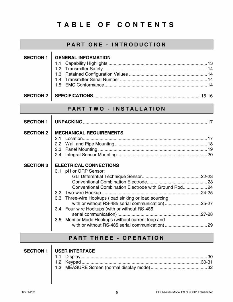
2.2 Wall and PipeMounting
Figure 2-1 illustrates how to wall or pipe mount the trans-mitter using the supplied GLI hardware kit. Determine themounting method, and attach the hardware as shown.
1. Fasten the wall/pipe adapter to the wall or pipe.
2. Using a blunt tool, open both cable entry knockoutholes in the back cover.
3. Insert-and-twist the back cover onto the installedwall/pipe adapter, and tighten its two screws to lockback cover onto the adapter.
4. Attach transmitter to back cover using its four captivescrews.
HORIZONTALPIPE MOUNT
PRO-SERIES BACK COVER
SCREWS(CUSTOMER SUPPLIED)
PRO-SERIESWALL/PIPE ADAPTER
WALL MOUNT
PRO-SERIESTRANSMITTER
STRAPS OR HOSE CLAMPS(CUSTOMER SUPPLIED)
VERTICALPIPE MOUNT
TWO SCREWS LOCK BACK COVER TOWALL/PIPE ADAPTER AFTERCOVER IS TWISTED ONTO ADAPTER.
FIGURE 2-1 Wall and Pipe Mounting Details

PART TWO - INSTALLATION SECTION 2 - MECHANICAL REQUIREMENTS
Rev. 1-202 PRO-series Model P3 pH/ORP Transmitter19
2.3 Panel Mounting
�
Figure 2-2 illustrates how to panel mount the transmitterusing the supplied GLI panel mount hardware kit.
1. Cut a 3.30-inch (84 mm) square cutout hole in panel.
2. Position panel-mount gasket over cutout in front ofpanel, and place retainer plate behind panel with itsfour threaded inserts facing away from back of panel.
3. Attach transmitter to retainer plate using its four captivescrews.
NOTE: If panel is too thick, remove captive screwsfrom transmitter, and use longer screws pro-vided in hardware kit.
FIGURE 2-2 Panel Mounting Details

PART TWO - INSTALLATION SECTION 2 - MECHANICAL REQUIREMENTS
PRO-series Model P3 pH/ORP Transmitter Rev. 1-20220
2.4 Integral SensorMounting
�
Figure 2-3 illustrates how to integrally mount the transmitteronto a sensor using the supplied GLI mounting hardware kit.
1. Using a blunt tool, open knockout hole in bottom ofswivel ball for routing the sensor cable.
2. Attach swivel-mount assembly onto back end of sensorusing coupling provided with GLI sensor (only sensorswith “PRO1” suffix in their part number) or an appropri-ately-sized coupling that you provide.
3. Insert-and-twist the back cover onto the installedswivel-mount assembly. Tighten its two screws to lockthe back cover onto the swivel-mount assembly.
NOTE: To change mounting angle, loosen swivel-mountassembly by lifting tab on bottom of swivel nut. Posi-tion to desired angle and re-tighten swivel nut.
4. Attach transmitter to back cover using its four captive screws.
GLI SENSOR(COUPLING AND SENSOR
APPEAR DIFFERENTLY FOR EACH MEASUREMENT TYPE)
COUPLING (SUPPLIED WITH GLI SENSOR THAT HAS "PRO1" SUFFIX IN SENSOR PART NUMBER)
BOTTOM OF SWIVEL NUT
SWIVEL-MOUNT ASSEMBLY (TO LOOSEN ASSEMBLY TO CHANGE MOUNTING ANGLE, LIFT TAB SLIGHTLY ON BOTTOM OF SWIVEL NUT)
TWO SCREWS LOCK BACK COVER TO SWIVEL-MOUNT ASSEMBLY AFTER COVER IS TWISTED ONTO ADAPTER.
PRO-SERIES TRANSMITTER
PRO-SERIES BACK COVER
TAB
SENSORCABLE
FIGURE 2-3 Integral Sensor Mounting Details

PART TWO - INSTALLATION SECTION 3 - ELECTRICAL CONNECTIONS
Rev. 1-202 PRO-series Model P3 pH/ORP Transmitter21
SECTION 3
�
�
Figure 2-4 shows the terminal block arrangement andterminal designations for the transmitter.
NOTE: All terminals are suitable for single wires up to 14AWG (2.5 mm2).
Wiring Tip! To comply with European Community (CE) electromag-netic compatibility requirements, follow these general wiring guidelines:
1. Locate transmitter as far as possible from motors and other non-CE certified devices with excessive electromagnetic emissions.
2. Use GLI-specified ferrites and cables. Failure to do so may elimi-nate compliance. Locate all ferrites as close as possible tothe transmitter.
� DC Power Supply Cable (GLI 1W0980 two-conductor plusshield): Connect cable shield to earth ground at the supplyend. Loop cable 2-1/2 times through ferrite (Steward#28B0686-200, Fair-Rite Corp. #2643665702, or equivalent).
� Sensor Cable: Keep cable shields as short as possible. At thetransmitter end, connect the outer shield to earth ground, andthe inner shield to the SHIELD terminal. If sensor cable hasone shield, connect it to the SHIELD terminal. In either case,clamp ferrite (Steward #28A2025-OAO, Fair-Rite Corp.#0431164281, or equivalent) on sensor cable.
� Analog mA Output Cable (four-wire hookup only -- GLI1W0980 two-conductor plus shield): Connect cable shield toearth ground at the supply end. Loop cable 2-1/2 timesthrough ferrite (Steward #28B0686-200, Fair-Rite Corp.#2643665702, or equivalent).
TB1 TB2
(Signal)Red
NC
(Reference)Green(Temp)Yellow/BlackShield
NC
(-5VDC)White
PRO-P-ESP: pH and ORP
Serial #: P
G0123456
3(-)
67
5
4
(+)12
3
67
5
4
12
2-W
ire C
onne
ctio
n
(See
man
ual f
or 3
, 4 W
ire C
onne
ctio
ns)
14-3
0 V
DC
Cla
ss 2
20m
A m
ax
FIGURE 2-4 Transmitter Terminal Designations
ELECTRICAL CONNECTIONS

PART TWO - INSTALLATION SECTION 3 - ELECTRICAL CONNECTIONS
PRO-series Model P3 pH/ORP Transmitter Rev. 1-20222
3.1 pH or ORP Sensor
GLI DifferentialTechnique Sensor
�
�
�
Depending on how transmitter is mounted, route the sensor(or interconnect) cable into the transmitter as follows:
• Wall/Pipe-mounted Transmitter: Route cable throughleft side cable entry knockout hole in the back cover.
• Panel-mounted Transmitter: Route cable behind panelto the exposed TB2 terminal strip.
• Integral Sensor-mounted Transmitter: Route cablethrough swivel ball knockout hole and center hole inback cover. (Do not open left side cable entry knockouthole in back cover.)
All GLI Differential Technique sensors have a built-in tem-perature element for automatic temperature compensationand for measuring process temperature.
Wiring Tip! Route the sensor cable in 1/2-inch,grounded metal conduit to protect it from moisture,electrical noise, and mechanical damage.
For installations where the distance between sensor andtransmitter exceeds the sensor cable length, indirectlyconnect the sensor to the transmitter using a junction boxand interconnect cable.
NOTE: Do not route the sensor cable in any conduit con-taining AC or DC power wiring (“electrical noise”may interfere with the sensor signal).
Refer to Figure 2-5 and connect the sensor (or intercon-nect) cable wires as shown, matching colors as indicated.
NOTE: For GLI Differential sensors with only one shieldwire, always connect it to Terminal 3 on TB2.
For systems not requiring CE compliance andlacking an earth ground, connect the outer shield toTerminal 3 on TB2.

PART TWO - INSTALLATION SECTION 3 - ELECTRICAL CONNECTIONS
Rev. 1-202 PRO-series Model P3 pH/ORP Transmitter23
ConventionalCombination Electrode
White 1 White (-5 VDC)
2
3 Shield/Black
4 Yellow (Temp)
5 Green (Ref.)
6
7 Red (Signal)
Shield and Black
Yellow
Green
Red
Inner
Outer Shield TO EARTH GROUND
FIGURE 2-5Connecting GLI Differential Technique Sensor
The electrode must be within 100 ft. (30 m) of the transmit-ter (985 ft./300 m for electrode with preamp). Refer toFigure 2-6 and directly connect the electrode’s coaxial ca-ble to the transmitter.
1. Connect the electrode’s reference signal -- braidedshield wire of coaxial cable (black insulated wire for GLIelectrode) -- to Terminal 5 on TB2.
2. Connect the electrode’s active signal -- center wire ofcoaxial cable (clear insulated wire for GLI electrode) --to Terminal 7 on TB2.
3. Connect a jumper between Terminals 3 and 5 on TB2.
4. Connect the electrode’s temperature element (typicallywhite and red insulated wires for GLI electrode) to Ter-minals 3 and 4 on TB2, attaching either wire to eitherterminal.
1
2
3 Shield/Black
4 Yellow (Temp)
5 Green (Ref.)
6
7 Red (Active)
COMBINATIONELECTRODE
COAXIALCABLE
TEMP COMP WIRES
BRAIDEDSHIELD
JUMPERREQUIRED
FIGURE 2-6Connecting Conventional Combination Electrode

PART TWO - INSTALLATION SECTION 3 - ELECTRICAL CONNECTIONS
PRO-series Model P3 pH/ORP Transmitter Rev. 1-20224
ConventionalCombination Electrode
with Ground Rod
3.2 Two-wire Hookup
�
Some applications require that an external ground rod beused with the combination electrode. The electrode must bewithin 100 ft. (30 m) of the transmitter (985 ft./300 m forelectrode with preamp). Refer to Figure 2-7 and directlyconnect the electrode’s coaxial cable to the transmitter.
Connect the electrode and temperature element wires in thesame way as described in the previous “Conventional Com-bination Electrode” subheading -- and also connect theground rod wire to Terminal 3 on TB2.
1
2
3 Shield/Black
4 Yellow (Temp)
5 Green (Ref.)
6
7 Red (Active)
COMBINATIONELECTRODE
COAXIALCABLE
TEMP COMP WIRES
BRAIDEDSHIELD
JUMPERREQUIRED
RODGROUND
FIGURE 2-7Connecting Conventional Combination Electrode with Ground Rod
In a two-wire hookup, at least 16 VDC is required for opera-tion. A load device can be connected in the current loop(see Figure 2-8 for details).
Depending on how the transmitter is mounted, route the DCpower/analog output wiring into the transmitter as follows:
• Wall/Pipe-mounted Transmitter: Route cable throughright side cable entry knockout hole in the back cover.
• Panel-mounted Transmitter: Route cable behind panelto the exposed TB1 terminal strip.
• Integral Sensor-mounted Transmitter: Route cablethrough right side cable entry knockout hole in the backcover. (Do not open left side cable entry knockout holein cover.)
Wiring Tip! Use high quality, shielded instrumentation cable.

PART TWO - INSTALLATION SECTION 3 - ELECTRICAL CONNECTIONS
Rev. 1-202 PRO-series Model P3 pH/ORP Transmitter25
5
76
1
34
2
-
Loop Power 16-30VDC Class 2
Loop Resistance(See nomograph)
+Jumper Required
16
0
600
300
RE
SIS
TA
NC
E
I
N O
HM
S
100
200
400
500
700
800
30
DC VOLTAGE
18 20 22 24 26 28
50 Ohms/VoltLOOP LOAD
FIGURE 2-8Two-wire Hookup
3.3 Three-wire Hookups
�
In a three-wire hookup, the transmitter can be wired fourways depending on load “sinking” or “sourcing” and whetheror not RS-485 serial communication is used. At least 14VDC is required for operation (16 VDC with serial communi-cation). When using RS-485, consult GLI for Command Set.
Depending on how the transmitter is mounted, route the DCpower, analog output, and RS-485 serial communicationwiring into the transmitter as follows:
• Wall/Pipe-mounted Transmitter: Route cable throughright side cable entry knockout hole in the back cover.
• Panel-mounted Transmitter: Route cable behind panelto the exposed TB1 terminal strip.
• Integral Sensor-mounted Transmitter: Route cablethrough right side cable entry knockout hole in the backcover. (Do not open left side cable entry knockout holein cover.)
Wiring Tip! Use high quality, shielded instrumentation cable.
PART TWO - INSTALLATION SECTION 3 - ELECTRICAL CONNECTIONS
PRO-series Model P3 pH/ORP Transmitter Rev. 1-20226
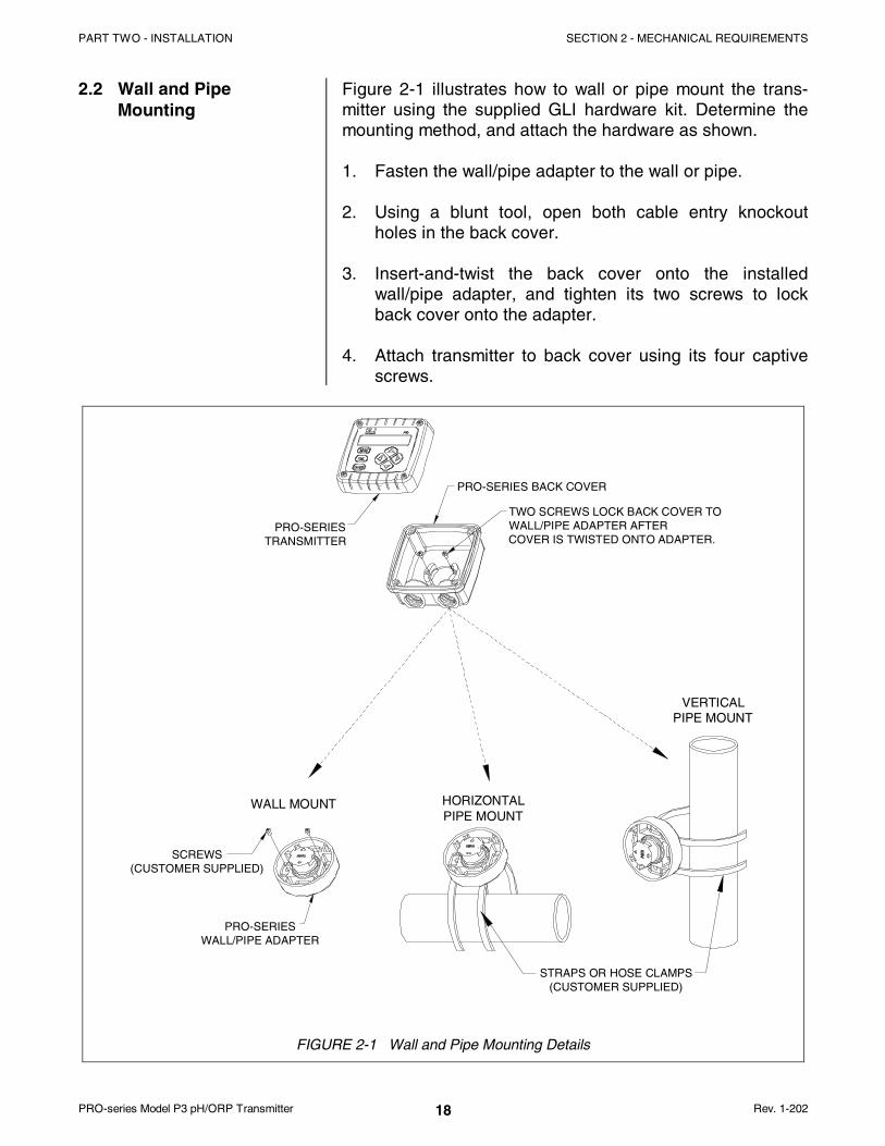
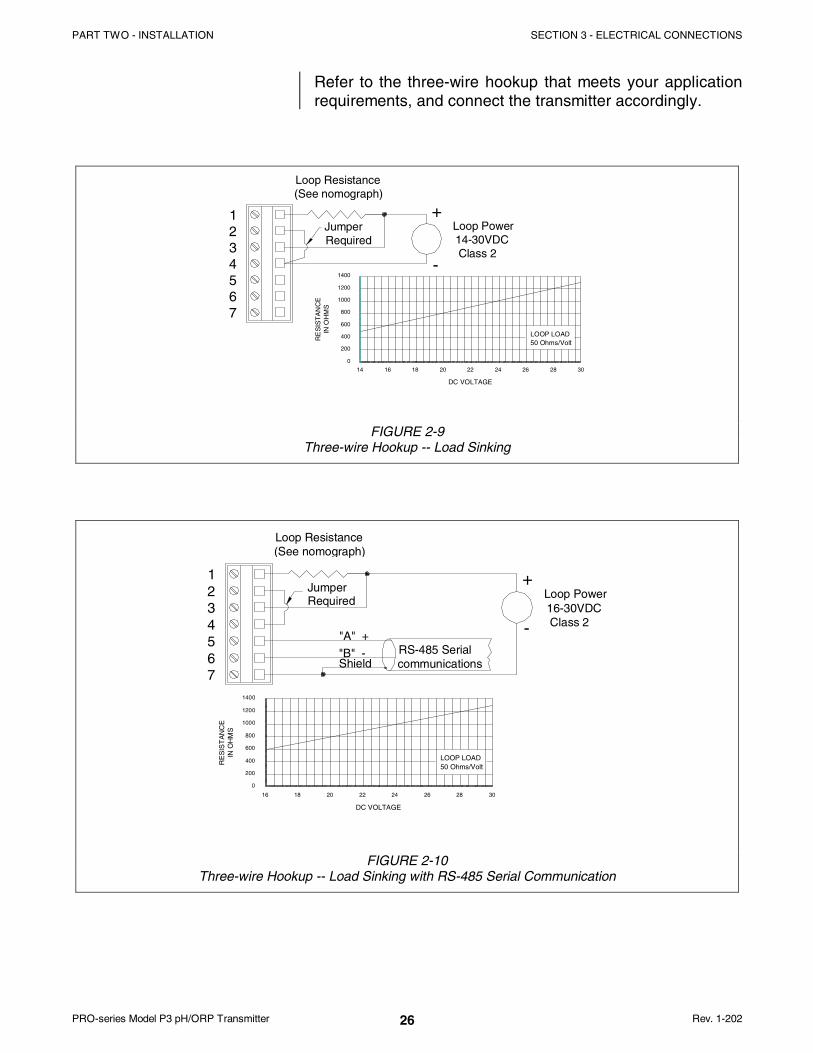
Refer to the three-wire hookup that meets your applicationrequirements, and connect the transmitter accordingly.
+1234567
-
Loop Resistance(See nomograph)
Jumper Required
200
0
14 16 18
RE
SIS
TA
NC
E
IN
OH
MS
800
400
600
1000
1200
1400
DC VOLTAGE
20 22 24 26 28 30
50 Ohms/VoltLOOP LOAD
Loop Power 14-30VDC Class 2
FIGURE 2-9Three-wire Hookup -- Load Sinking
RS-485 Serialcommunications
"A" +
"B" -
+1234567
-
Loop Resistance(See nomograph)
JumperRequired
DC VOLTAGE
1000
RE
SIS
TA
NC
E
I
N O
HM
S
400
0
200
600
800
1200
1400
16 18 20 22
LOOP LOAD50 Ohms/Volt
2624 28 30
Loop Power 16-30VDC Class 2
Shield
FIGURE 2-10Three-wire Hookup -- Load Sinking with RS-485 Serial Communication

PART TWO - INSTALLATION SECTION 3 - ELECTRICAL CONNECTIONS
Rev. 1-202 PRO-series Model P3 pH/ORP Transmitter27
+1234567
-Loop Resistance(See nomograph)
Jumper Required
200
0
14 16 18
RE
SIS
TA
NC
E
IN
OH
MS
800
400
600
1000
1200
1400
DC VOLTAGE
20 22 24 26 28 30
50 Ohms/VoltLOOP LOAD
Loop Power 14-30VDC Class 2
FIGURE 2-11Three-wire Hookup -- Load Sourcing
RS-485 Serialcommunications
"A" +
"B" -
+1234567
-
Loop Resistance(See nomograph)
Loop Power16-30VDCClass 2
DC VOLTAGE
1000
RE
SIS
TA
NC
E
I
N O
HM
S
400
0
200
600
800
1200
1400
16 18 20 22
LOOP LOAD50 Ohms/Volt
2624 28 30
Shield
FIGURE 2-12Three-wire Hookup -- Load Sourcing with RS-485 Serial Communication
3.4 Four-wire Hookups In a four-wire hookup, the transmitter can be wired two waysdepending on whether or not RS-485 serial communicationis used. At least 12 VDC is required for operation (16 VDCwith serial communication). When using RS-485, consultGLI for Command Set.
Depending on how the transmitter is mounted, route the DCpower, analog output, and RS-485 serial communicationwiring into the transmitter as follows:
• Wall/Pipe-mounted Transmitter: Route cable throughright side cable entry knockout hole in the back cover.

PART TWO - INSTALLATION SECTION 3 - ELECTRICAL CONNECTIONS
PRO-series Model P3 pH/ORP Transmitter Rev. 1-20228
�
• Panel-mounted Transmitter: Route cable behind panelto the exposed TB1 terminal strip.
• Integral Sensor-mounted Transmitter: Route cablethrough right side cable entry knockout hole in the backcover. (Do not open left side cable entry knockout holein cover.)
Wiring Tip! Use high quality, shielded instrumentation cable.
Refer to the four-wire hookup that meets your applicationrequirements, and connect the transmitter accordingly.
5
76
1
34
2
-
Loop Resistance(See nomograph)
+
-
+
1000
RE
SIS
TA
NC
E
I
N O
HM
S
161412
400
200
0
800
600
1400
1200
LOOP LOAD50 Ohms/Volt
2624222018
DC VOLTAGE
3028
Loop Power 12-30VDC Class 2
External Power 12-30VDC Class 2
FIGURE 2-13Four-wire Hookup without RS-485 Serial Communication
5
76
1
34
2
-RS-485 Serialcommunications
"B" -
"A" +
Loop Resistance(See nomograph)
+
-
+
Loop Power 12-30VDC Class 2
External Power 16-30VDC Class 2
Shield
DC VOLTAGE
1000
RE
SIS
TA
NC
E
IN
OH
MS
400
0
200
600
800
1200
1400
12 14 16 18 2220 24 26 28 30
LOOP LOAD50 Ohms/Volt
FIGURE 2-14Four-wire Hookup with RS-485 Serial Communication

PART TWO - INSTALLATION SECTION 3 - ELECTRICAL CONNECTIONS
Rev. 1-202 PRO-series Model P3 pH/ORP Transmitter29
3.5 Monitor ModeHookups (withoutcurrent loop)
�
The transmitter can be wired two ways in a monitor modehookup (without current loop), depending on whether or notRS-485 serial communication is used. At least 12 VDC isrequired for operation (16 VDC with serial communication).When using RS-485, consult GLI for Command Set.
Depending on how the transmitter is mounted, route the DCpower and RS-485 serial communication wiring into thetransmitter as follows:
• Wall/Pipe-mounted Transmitter: Route cable throughright side cable entry knockout hole in the back cover.
• Panel-mounted Transmitter: Route cable behind panelto the exposed TB1 terminal strip.
• Integral Sensor-mounted Transmitter: Route cablethrough right side cable entry knockout hole in the backcover. (Do not open left side cable entry knockout holein cover.)
Wiring Tip! Use high quality, shielded instrumentation cable.
Refer to the monitor mode hookup that meets your applica-tion requirements, and connect the transmitter accordingly.
+
1234567
-
External Power 12-30VDC Class 2
FIGURE 2-15Monitor Mode Hookup (without Current Loop) -- without RS-485 Serial Communication
+
1234567
-RS-485 Serialcommunication
"B" -
"A" +External Power 16-30VDC Class 2
Shield
FIGURE 2-16Monitor Mode Hookup (without Current Loop) -- with RS-485 Serial Communication

PART THREE - OPERATION SECTION 1 - USER INTERFACE
PRO-series Model P3 pH/ORP Transmitter Rev. 1-20230
P A R T T H R E E - O P E R A T I O N
SECTION 1
1.1 Display
1.2 Keypad
The user interface consists of a two-line LCD display and akeypad with MENU, ENTER, ESC, ÕÕ, ÖÖ, ××, and ØØ keys.
By using the keypad, you can display three types ofscreens:
• MEASURE Screens: The normal display mode shows themeasured pH (or ORP). Pressing the ÖÖ key sequentiallyscrolls through these other measurement readouts:
� Measured process temperature� Measured pH and temperature� Measured analog output mA value
• MENU Screens: These top-level and lower-level (sub-menu) screens within the three main branches of themenu tree are used to access edit/selection screens forconfiguration. (EXIT screens at the end of each menubranch enable you to move up one level in the menu treeby pressing the ENTER key. This is functionally the sameas pressing the ESC key.)
• Edit/Selection Screens: These screens enter values/choices to calibrate, configure, and test the transmitter.
The keypad enables you to move throughout the transmittermenu tree. The keys and their related functions are:
1. MENU key: Pressing this key with the MEASUREscreen displayed shows the “MAIN MENU CALIBRATE”screen. To display the CONFIGURE or TEST/MAINTtop-level main branch screen, press the ØØ key. Press-ing the MENU key with a menu screen displayedalways shows the top-level screen in that branch.(Pressing the MENU key also “aborts” the procedure tochange values or selections.)
USER INTERFACE
not provided when usingtransmitter to measure ORP}

PART THREE - OPERATION SECTION 1 - USER INTERFACE
Rev. 1-202 PRO-series Model P3 pH/ORP Transmitter31
2. ENTER key: Pressing this key does two things: it dis-plays submenu and edit/selection screens, and it enters(saves) configuration values/selections.
3. ESC key: Pressing this key always takes the display upone level in the menu tree. (Example: With the “MAINMENU” screen displayed, pressing the ESC key oncetakes the display up one level to the MEASUREscreen.) The ESC key can also “abort” the procedure tochange a value or selection.
4. ÕÕ and ÖÖ keys: Depending on the type of displayedscreen, these keys do the following:
• MEASURE Screen: Changes readout (in continuousloop sequence) to show different measurements.
• Menu Screens: These keys are non-functional.
• Edit/Selection Screens: Moves cursor left or right toselect digit for adjustment with ×× and ØØ keys.
5. ×× and ØØ keys: Depending on the type of displayedscreen, these keys do the following:
• MEASURE Screen: These keys are non-functional.
• Menu Screens: Moves up or down respectivelybetween other same-level menu screens.
• Edit/Selection Screens: Adjusts selected digit valueup or down, or moves up or down between choices.
FIGURE 3-1 Transmitter Keypad

PART THREE - OPERATION SECTION 1 - USER INTERFACE
PRO-series Model P3 pH/ORP Transmitter Rev. 1-20232
1.3 MEASURE Screen(normal display mode)
�
�
The MEASURE screen is normally displayed. Pressing theMENU key temporarily replaces the MEASURE screen withthe top-level “MAIN MENU CALIBRATE” branch selectionscreen. Using the keypad, you can then display otherscreens to calibrate, configure or test the transmitter. If thekeypad is not used within 30 minutes, except duringcalibration or while using specific transmitter test/maintenance functions, the display will automaticallyreturn to the MEASURE screen. To display the MEASUREscreen at any time, press the MENU key once and thenpress the ESC key once.
When using the transmitter to measure pH, the MEASUREscreen can show four different readout versions. To selectbetween them, in continuous loop sequence, press theÕÕ or ÖÖ key. These are examples of the different versions:
Ö Ö
Ö Ö
NOTE: If pure water temperature compensation was se-lected (PART THREE, Section 3.2, subheading“Select PURE H2O COMP”) the MEASURE screenwill show an asterisk after the pH reading to indi-cate it is being applied.
When using the transmitter to measure ORP, only tworeadouts are shown: measured mV and the mA output. Thetwo screens showing temperature are not available.
NOTE: When the transmitter returns to its normalMEASURE screen mode, the appearing readout isalways the version last selected.
Note that three MEASURE screen readout exam-ples show the factory-default “PH” notation on theirtop lines, illustrating the transmitter notation feature.To create your own notation, refer to PARTTHREE, Section 3.2, subheading “ENTER NOTE(top line of MEASURE screen).”
When the measured value is beyond the transmitter meas-uring range, a series of “ + ” or “ - ” screen symbols appear,respectively indicating that the value is above or belowrange.
PART THREE - OPERATION SECTION 2 - MENU STRUCTURE
Rev. 1-202 PRO-series Model P3 pH/ORP Transmitter33
SECTION 2
�
2.1 DisplayingMain BranchSelection Screens
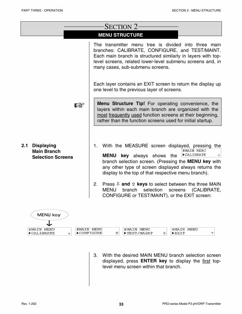
The transmitter menu tree is divided into three mainbranches: CALIBRATE, CONFIGURE, and TEST/MAINT.Each main branch is structured similarly in layers with top-level screens, related lower-level submenu screens and, inmany cases, sub-submenu screens.
Each layer contains an EXIT screen to return the display upone level to the previous layer of screens.
Menu Structure Tip! For operating convenience, thelayers within each main branch are organized with themost frequently used function screens at their beginning,rather than the function screens used for initial startup.
1. With the MEASURE screen displayed, pressing the
MENU key always shows the branch selection screen. (Pressing the MENU key withany other type of screen displayed always returns thedisplay to the top of that respective menu branch).
2. Press ØØ and ×× keys to select between the three MAINMENU branch selection screens (CALIBRATE,CONFIGURE or TEST/MAINT), or the EXIT screen:
3. With the desired MAIN MENU branch selection screendisplayed, press ENTER key to display the first top-level menu screen within that branch.
MENU STRUCTURE
PART THREE - OPERATION SECTION 2 - MENU STRUCTURE
PRO-series Model P3 pH/ORP Transmitter Rev. 1-20234
2.2 DisplayingTop-levelMenu Screens
�
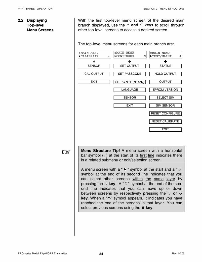
With the first top-level menu screen of the desired mainbranch displayed, use the ØØ and ×× keys to scroll throughother top-level screens to access a desired screen.
The top-level menu screens for each main branch are:
Ð Ð Ð
SENSOR SET OUTPUT STATUS
CAL OUTPUT SET PASSCODE HOLD OUTPUT
EXIT SET °C or °F (pH only) OUTPUT
LANGUAGE EPROM VERSION
SENSOR SELECT SIM
EXIT SIM SENSOR
RESET CONFIGURE
RESET CALIBRATE
EXIT
Menu Structure Tip! A menu screen with a horizontalbar symbol ( ) at the start of its first line indicates thereis a related submenu or edit/selection screen.
A menu screen with a “ ” symbol at the start and a “ÈÈ”symbol at the end of its second line indicates that youcan select other screens within the same layer bypressing the ØØ key. A “ ↕ ” symbol at the end of the sec-ond line indicates that you can move up or downbetween screens by respectively pressing the ×× or ØØkey. When a “ÇÇ” symbol appears, it indicates you havereached the end of the screens in that layer. You canselect previous screens using the ×× key.
____________

PART THREE - OPERATION SECTION 2 - MENU STRUCTURE
Rev. 1-202 PRO-series Model P3 pH/ORP Transmitter35
2.3 DisplayingSubmenu Screens
2.4 AdjustingEdit/SelectionScreen Values
2.5 Entering (Storing)Edit/Selection ScreenValues/Choices
�
After selecting a top-level menu screen, press the ENTERkey to display a related submenu or edit/selection screen:
• Submenu Screens are usually linked to other relatedsame-level screens. Pressing the ØØ key displays theseother related menu screens.
Example: With this submenu screen displayed:
pressing the ØØ key displays this related,same-level submenu screen:
• Edit/Selection Screens always have a first line endingwith a “?”. Pressing the ØØ or ×× key changes the value/choice enclosed by parenthesis (second line on screen).
Example: With this submenu screen displayed:
pressing the ØØ key displays this related choice:
Use arrow keys to edit/change the value/choice enclosedby parenthesis (examples shown above and below).
A choice can be changed by simply using the ×× and ØØkeys. Numerical values can be adjusted using the ÕÕ and ÖÖkeys to select a digit, and ×× and ØØ keys to adjust its value.
With the desired value/choice displayed, press the ENTERkey to enter (store) it into the non-volatile transmitter mem-ory. The previous screen will then re-appear.
NOTE: You can always press the ESC key to abort savinga new setting. The original setting will be retained.

PART THREE - OPERATION SECTION 3 - TRANSMITTER CONFIGURATION
PRO-series Model P3 pH/ORP Transmitter Rev. 1-20236
SECTION 3
�
3.1 Selecting LANGUAGEto Operate Transmitter
�
3.2 ConfiguringSensor Characteristics
SELECT SENSOR Type
NOTE: When the passcode feature is enabled (Section3.5), you must successfully enter the passcodebefore attempting to enter a configuration setting.
The transmitter is normally equipped to display screens inEnglish and Spanish (Español). However, another languagesuch as French (Français), German (Deutsche), etc. may besubstituted for Spanish. The transmitter is factory-set forEnglish. To select the other language:
1. Press MENU key to display a “MAIN MENU screen.
If the screen is not showing, useØØ or ×× key to display it.
2. Press ENTER key to display .
3. Press ØØ key until screen appears.
4. Press ENTER key to display . UseØØ or ×× key to select a language, and press ENTERkey to enter it.
NOTE: After a language is selected and entered, allscreens are displayed in that language.
The transmitter must be configured to define the sensorused with it, and other related items such as the displayformat, desired buffer set for calibration, temperature ele-ment, input signal filtering, etc.
1. With the screen displayed, press
ØØ key once to display .
TRANSMITTER CONFIGURATION

PART THREE - OPERATION SECTION 3 - TRANSMITTER CONFIGURATION
Rev. 1-202 PRO-series Model P3 pH/ORP Transmitter37
SelectDISPLAY FORMAT
2. Press ENTER key to display .
3. Press ENTER key again to display a screen like
. Use ØØ and ×× keys to select thetype of sensor to be used with the transmitter, andpress ENTER key to enter it:
• DIFF pH: Selects GLI Differential pH sensor.
• COMBINATION pH: Selects conventional combi-nation pH electrode.
• ORP: Selects ORP sensor (either a GLI DifferentialORP sensor or a conventional combination ORPelectrode).
WARNING:
CHANGING THE SENSOR TYPE AUTOMATIC-ALLY REPLACES ALL USER-ENTERED CONFIG-URATION VALUES WITH FACTORY-DEFAULTS.
When using the transmitter to measure ORP, this func-tion is not provided. (The ORP display format is fixed toshow mV values as only whole numbers.) For pH measure-ment, select the desired display format (XX.XX or XX.X) forthe MEASURE screen. This format setting has no effect onedit/selection screens, which always show pH values in aXX.XX format.
1. With the screen displayed, press
ØØ key once to display .
2. Press ENTER key to display a screen like
. Use ØØ and ×× keys to select thedesired format (XX.XX or XX.X), and press ENTER keyto enter it.

PART THREE - OPERATION SECTION 3 - TRANSMITTER CONFIGURATION
PRO-series Model P3 pH/ORP Transmitter Rev. 1-20238
SELECT BUFFER Setfor pH Calibration
�
SelectPURE H2O COMP (onlyfor special applications)
�
When using the transmitter to measure ORP, this func-tion is not provided. For pH measurement, configure thetransmitter to use one of these buffer sets for pH calibration:
• 4.00, 7.00, and 10.00• DIN 19267 Standard (1.09, 4.65, 6.79, 9.23, and 12.75)
NOTE: When using buffers that are not included in either ofthe transmitter buffer sets, disregard selecting thebuffer set. In this case, use only the “1 (or) 2 POINTSAMPLE” method for pH calibration.
The transmitter automatically recognizes pH values from theselected buffer set and uses its associated built-in table ofpH-versus-temperature values to improve measurement ac-curacy. To select a buffer set:
1. With the screen displayed, press
ØØ key once to display .
2. Press ENTER key to display a screen like
. Use ØØ and ×× keys to select abuffer set (4, 7, 10 or DIN 19267) for use during cali-bration, and press ENTER key to enter it.
When using the transmitter to measure ORP, this func-tion is not provided. When measuring pH in solutions withthe weakly dissociating electrolytes ammonia or morpholine,built-in tables provide a correction factor for pure watertemperature compensation. This special compensation isspecifically for use in power plant applications. It adds anassociated temperature-dependent offset, from the selectedtable, to the measured pH. If custom compensation is re-quired for pure water applications, a “user-defined” pH/°Clinear slope factor can be applied to the measured pH.
NOTE: The selected pure water temperature compensationis limited to 50°C. If the process temperature ishigher, the offset corresponding to 50°C is used.
1. With the screen displayed, press
ØØ key once to display .

PART THREE - OPERATION SECTION 3 - TRANSMITTER CONFIGURATION
Rev. 1-202 PRO-series Model P3 pH/ORP Transmitter39
�
SET FILTER Time
2. Press ENTER key to display .
3. Press ENTER key again to display a screen like
. Use ØØ and ×× keys to select thedesired pure water temperature compensation (NONE,AMMONIA, MORPHOLINE or USER DEFINED), andpress ENTER key to enter it.
4. If “USER DEFINED” was selected, you must set thespecific pH/°C linear slope:
A. With the screen displayed,
press ØØ key once to display .
B. Press ENTER key to display a screen like
. Use arrow keys to adjust toa desired slope, and press ENTER key to enter it.
NOTE: The MEASURE screen will show an asterisk afterthe pH reading to indicate pure water temperaturecompensation was selected and is being applied.
A time constant (in seconds) can be set to filter or “smoothout” the sensor signal. A minimum value of “0 seconds” hasno smoothing effect. A maximum value of “60 seconds” pro-vides maximum smoothing. Deciding what sensor signalfilter time to use is a compromise. The higher the filter time,the longer the sensor signal response time will be to achange in the actual process value.
1. With the screen displayed, press
ØØ key once to display .
2. Press ENTER key to display a screen like
. Use arrow keys to adjust to adesired filter time, and press ENTER key to enter it.

PART THREE - OPERATION SECTION 3 - TRANSMITTER CONFIGURATION
PRO-series Model P3 pH/ORP Transmitter Rev. 1-20240
ENTER NOTE (top lineof MEASURE screen)
SelectTEMP ELEMENT
Type
�
The top line of the MEASURE screen readouts that sepa-rately show the measurement, temperature, and analogoutput values are factory set to read “PH.” This notation canbe changed, for example, to “BASIN 1” to tailor the trans-mitter MEASURE screen to the application. The top linewould then be “MEASURE BASIN 1.” The notation is limitedto eight characters which can be a combination of capitalletters A through Z, numbers 0 through 9, spaces, # sym-bols, hyphens, and periods.
1. With the screen displayed, press
ØØ key once to display .
2. Press ENTER key to display .Create the desired notation on the second line:
A. Starting with extreme left character position, use×× and ØØ keys to select the desired first character.
B. Press ÖÖ key once to select the next character, anduse ×× and ØØ keys to select its desired character.
C. Repeat procedure until desired notation is displayed.
3. Press ENTER key to enter the displayed notation.
When using the transmitter to measure ORP, this func-tion is not provided since ORP measurement does notrequire temperature compensation. When measuring pH,configure the transmitter for either automatic temperaturecompensation (by defining the sensor’s built-in temperatureelement or an external element) or fixed MANUAL tem-perature compensation. When using MANUAL you mustdetermine and enter a specific temperature.
NOTE: When a temperature element type has been se-lected but the element is not connected to thetransmitter, a “WARNING: CHECK STATUS” mes-sage will appear. To prevent or clear the message,connect the element or select “MANUAL.”
1. With the screen displayed, press
ØØ key once to display .

PART THREE - OPERATION SECTION 3 - TRANSMITTER CONFIGURATION
Rev. 1-202 PRO-series Model P3 pH/ORP Transmitter41
3.3 SET °C OR °F(temperature displayformat)
2. Press ENTER key to display .
3. Press ENTER key again to display a screen like
. Use ØØ and ×× keys to select thetype of temperature element used with the pH sensor tocompensate the measurement, and press ENTER keyto enter it:
• NTC300: Selects automatic temperature compensa-tion using only a NTC 300 ohm thermistortemperature element (in all GLI Differential pH sen-sors -- except Model 6006P4-2000 pure water pHsensor systems which use a Pt 1000 RTD).
• PT1000: Selects automatic temperature compensa-tion using only a Pt 1000 RTD temperature element.
• PT100: Selects automatic temperature compensa-tion using only a Pt 100 RTD temperature element.
• MANUAL: For pH measurement only -- selects fixedmanual temperature compensation (disregards tem-perature element -- see step 4).
4. If “MANUAL” was selected, you must set the specificmanual temperature compensation value:
A. With the screen displayed,
press ØØ key once to display .
B. Press ENTER key to display a screen like
. Use arrow keys to adjust toa desired temperature for fixed MANUAL compen-sation, and press ENTER key to enter it.
When using the transmitter to measure ORP, this func-tion is not provided. When measuring pH, the temperaturecan also be displayed. The MEASURE screen can be set todisplay temperature values in °C or °F. In either case, dis-play resolution for measured temperature is always “XX.X.”

PART THREE - OPERATION SECTION 3 - TRANSMITTER CONFIGURATION
PRO-series Model P3 pH/ORP Transmitter Rev. 1-20242
3.4 ConfiguringAnalog Output
SET PARAMETER(representation)
1. With the or screen displayed, press ESC key twice to display
.
2. Press ×× key -- not ØØ key -- twice to display
.
3. Press ENTER key to display a screen like
. Use ØØ and ×× keys to select thedisplayed temperature units (°C or °F), and pressENTER key to enter it.
The transmitter provides an isolated 4-20 mA analog output.During normal measurement operation, the output is activebut can be held at the last measured value for up to 30 min-utes by using the “HOLD OUTPUT” function in theTEST/MAINT menu. (See PART THREE, Section 5.2 fordetails.) During calibration, the output is automatically heldat the last measured value and, upon completion, returnedto its active state.
When using the transmitter to measure ORP, this func-tion is not provided. (The output always represents themeasured ORP.) When measuring pH, the output can beassigned to represent the SENSOR (measured pH) ormeasured TEMPERATURE.
1. With the screen displayed, press ××
key -- not ØØ key -- twice to display .
2. Press ENTER key to display .
3. Press ENTER key again to display .Use ØØ and ×× keys to select the parameter the outputwill represent, press ENTER key to enter it.

PART THREE - OPERATION SECTION 3 - TRANSMITTER CONFIGURATION
Rev. 1-202 PRO-series Model P3 pH/ORP Transmitter43
SET 4 mA and20 mA VALUES(range expand)
�
SET FILTER Time
Parameter values can be set to define the endpoints atwhich the 4 mA and 20 mA analog output values are desired.
1. With the screen displayed, press
ØØ key once to display .
2. Press ENTER key to display a screen like
. Use arrow keys to set the valueat which 4 mA is desired, and press ENTER key to en-ter it.
3. After the screen re-appears, press
ØØ key once to display .
4. Press ENTER key to display a screen like
. Use arrow keys to set the valueat which 20 mA is desired, and press ENTER key toenter it.
NOTE: If the same values are set for 4 mA and 20 mA, theoutput automatically goes to, and remains at, 20 mA.
A time constant (in seconds) can be set to filter or “smoothout” the analog output signal. A minimum value of “0 sec-onds” has no smoothing effect. A maximum value of “60seconds” provides maximum smoothing. Deciding what out-put filter time to use is a compromise. The higher the filtertime, the longer the analog output signal response time willbe to a change in the measured value.
1. With the screen displayed, press
ØØ key once to display .
2. Press ENTER key to display a screen like
. Use arrow keys to adjust to adesired filter time, and press ENTER key to enter it.

PART THREE - OPERATION SECTION 3 - TRANSMITTER CONFIGURATION
PRO-series Model P3 pH/ORP Transmitter Rev. 1-20244
SET FAIL LEVEL Mode(off, 4 mA or 20 mA)
When a “WARNING CHECK STATUS” message appears,indicating that a system problem may exist, the analog out-put can be set to respond in one of three ways:
• OFF: Output remains active.• 4mA: Output automatically goes to and remains at 4 mA.• 20mA: Output automatically goes to and remains at 20 mA.
To SET FAIL LEVEL mode to suit your application:
1. With the screen displayed, press
ØØ key once to display .
2. Press ENTER key to display . UseØØ and ×× keys to select a response mode (OFF, 4mA or20mA), and press ENTER key to enter it.

PART THREE - OPERATION SECTION 3 - TRANSMITTER CONFIGURATION
Rev. 1-202 PRO-series Model P3 pH/ORP Transmitter45
3.5 SET PASSCODE(feature enabledor disabled)
The transmitter has a passcode feature to restrict access toconfiguration settings and calibration to only authorizedpersonnel.
• DISABLED: With the passcode feature disabled, all con-figuration settings can be displayed and changed, and thetransmitter can be calibrated.
• ENABLED: With the passcode feature enabled, all con-
figuration settings can be displayed -- but they cannot bechanged -- and the CALIBRATE and TEST/MAINT menuscannot be accessed without the passcode. When you at-tempt to change a setting in the CONFIGURE menu bypressing the ENTER key, a displayed notification re-quests passcode entry. A valid passcode entry saves thechanged setting and returns the display to the “MAINMENU” branch selection screen. An incorrect passcodeentry causes the display to momentarily show an errornotification before returning to the “MAIN MENU” branchselection screen. There is no limit on attempts to enter avalid passcode.
The passcode is factory-set to “3 4 5 6.” It cannot be changed.
To enable or disable the passcode feature:
1. Press MENU key to display a “MAIN MENU” screen.
If the screen is not showing, useØØ or ×× key to display it.
2. Press ENTER key to display .
3. Press ØØ key once to display .
4. Press ENTER key to display . UseØØ and ×× keys to select the desired passcode mode(DISABLED or ENABLED), and press ENTER key toenter it.

PART THREE - OPERATION SECTION 3 - TRANSMITTER CONFIGURATION
PRO-series Model P3 pH/ORP Transmitter Rev. 1-20246
3.6 Configuration SettingSummary
TABLE A lists all configuration settings and their entryranges/choices and factory defaults, categorized by basicfunctions.
TABLE A -- Transmitter Configuration Settings (Ranges/Choices and Defaults)
Displayed Screen Title Entry Range or Choices (where applicable) Factory Default Your Setting
LANGUAGE Setting
LANGUAGE? ENGLISH and SPANISH (French, German,etc. may be substituted for Spanish)
ENGLISH
SENSOR Settings
SELECT SENSOR? DIFF pH, COMB pH or ORP DIFF pH
DISPLAY FORMAT? pH: XX.XX pH or XX.X pHORP: Fixed at XXXX mV
pH: XX.XX pHORP: XXXX mV
SELECT BUFFER? pH: 4, 7, 10 or DIN 19267ORP: Screen not applicable/provided.
pH: 4, 7, 10ORP: Not applicable
PURE H2O COMPSELECT TYPE?
pH: NONE, AMMONIA MORPHOLINE orUSER DEFINED
ORP: Screen not applicable/provided.
pH: NONE
ORP: Not applicable
SET FILTER? 0-60 seconds 0 seconds
ENTER NOTE? pH: Replace PH with up to eight charactersORP: Replace ORP with up to eight characters
pH: PHORP: ORP
TEMP ELE:SELECT TYPE?
pH: NTC300, PT1000, PT100 or MANUALORP: Screen not applicable/provided.
pH: NTC300ORP: Not applicable
TEMP ELE:SET MANUAL?
pH: 0.0-100.0°CORP: Screen not applicable/provided.
pH: 25.0°CORP: Not applicable
TEMPERATURE Display Setting
SET °C OR °F? pH: °C or °FORP: Screen not applicable/provided.
pH: °CORP: Not applicable
OUTPUT Settings
SET PARAMETER? pH: SENSOR or TEMPERATUREORP: Screen not applicable/provided.
pH: SENSORORP: Not applicable
SET 4mA VALUE? pH: -2.00 to +14.00 pHORP: -2100 to +2100 mVTEMP:-20.0 to +200.0°C or -4.0 to 392.0°F
pH: 0.00 pHORP: 0 mVTEMP:0.0°C or 32.0°F
SET 20mA VALUE? pH: -2.00 to +14.00 pHORP: -2100 to +2100 mVTEMP:-20.0 to +200.0°C or -4.0 to 392.0°F
pH: 14.00 pHORP: +2100 mVTEMP:200.0°C or 392.0°F
SET FILTER? 0-60 seconds 0 seconds
SET FAIL LEVEL? OFF, 4 mA or 20 mA OFF
PASSCODE Setting
SET PASSCODE? DISABLED or ENABLED DISABLED
TEST/MAINT Simulation Function Settings
SELECT SIM? pH: SENSOR or TEMPERATUREORP: Screen not applicable/provided.
pH: SENSORORP: Not applicable
SIM SENSOR? pH: -2.00 to +14.00 pHORP: -2100 to +2100 mVTEMP:-20.0 to +200.0°C or -4.0 to 392.0°F
Present measured value ofsensor’s selected parameter(pH, ORP or temperature)

PART THREE - OPERATION SECTION 4 - TRANSMITTER CALIBRATION
Rev. 1-202 PRO-series Model P3 pH/ORP Transmitter47
SECTION 4
4.1 Important Information
Calibrate Periodically
�
Temperature-correctedpH Measurement
�
Four methods are available for pH calibration (Section 4.2).To calibrate ORP, use only the 1-POINT SAMPLE methoddescribed in Section 4.3. The analog output loop can also becalibrated (Section 4.4).
To maintain best measurement accuracy, periodically cali-brate the transmitter. Performance of the pH or ORP sensorslowly degrades over time, eventually causing inaccuratereadings. The time period between calibrations, and therate of system drift, can vary considerably with each appli-cation and its specific conditions.
Calibration Tip! Establish a maintenance program tokeep the sensor relatively clean and the transmitter cali-brated. The daily, weekly or monthly intervals betweenperforming maintenance will be influenced by the char-acteristics of the process solution, and can only bedetermined by operating experience.
The transmitter is factory-calibrated for accurate temperaturemeasurement. It will provide pH readings that are automaticallycorrected for temperature changes when the transmitter:
• Receives a temperature signal from a pH sensor thathas a built-in temperature element (all GLI Differentialsensors) or from an external temperature element.
• Has been correctly set for the type of temperatureelement being used for automatic compensation.
NOTE: When the passcode feature is enabled (Section3.5), you must successfully enter the passcodebefore attempting to calibrate the transmitter.
An in-progress calibration can always be abortedby pressing the ESC key. After the “ABORT: YES?”screen appears, do one of the following:
• Press ENTER key to abort. After the “CONFIRMACTIVE?” screen appears, press ENTER key toreturn the analog output to its active state(MEASURE screen appears).
• Press ×× or ØØ key to choose “ABORT: NO?” screen,and press ENTER key to continue calibration.
TRANSMITTER CALIBRATION

PART THREE - OPERATION SECTION 4 - TRANSMITTER CALIBRATION
PRO-series Model P3 pH/ORP Transmitter Rev. 1-20248
�
4.2 pH Calibration
�
2 POINT BUFFER Method
�
Calibration Tip! If a “CONFIRM FAILURE?” screen ap-pears during calibration, press ENTER key to confirm.Then, use ×× or ØØ key to select between “CAL: EXIT” or“CAL: REPEAT” and do one of the following:
• With “(CAL: EXIT)” selected, press ENTER key. Afterthe “CONFIRM ACTIVE?” screen appears, pressENTER key to return the analog output to its activestate (MEASURE screen appears).
• With “(CAL: REPEAT)” selected, press ENTER key torepeat calibration of the point.
Based on convenience and your application requirements,use one of the four methods provided for pH calibration.
CAUTION:
WHEN USING A NEW SENSOR OR REPLACING THESTANDARD CELL SOLUTION AND SALT BRIDGE ONAN EXISTING GLI DIFFERENTIAL SENSOR, ALWAYSPERFORM A “RESET CALIBRATE” USING THETEST/MAINT MENU (PART THREE, SECTION 5.8)BEFORE CALIBRATING.
NOTE: When calibrating a sensor for the first time, alwaysuse a two-point method for best accuracy.
This recommended method requires two buffers, typicallypH 7 and pH 4. (pH 10 buffer is also readily available but isnot as stable, particularly at extreme temperatures.) Thismethod automatically recognizes buffers from the selectedbuffer set. Therefore, you must use buffers that matchvalues in the buffer set (see PART THREE, Section 3.2,subheading “SELECT BUFFER Set for pH Calibration” fordetails.)
NOTE: When using buffers that are not included in either ofthe transmitter buffer sets, disregard this calibrationmethod. Instead, use only the “2 POINT SAMPLE”calibration method.
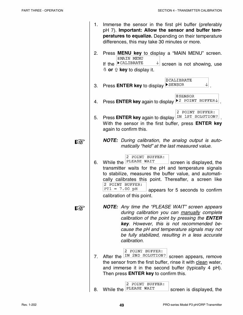
PART THREE - OPERATION SECTION 4 - TRANSMITTER CALIBRATION
Rev. 1-202 PRO-series Model P3 pH/ORP Transmitter49
�
�
1. Immerse the sensor in the first pH buffer (preferablypH 7). Important: Allow the sensor and buffer tem-peratures to equalize. Depending on their temperaturedifferences, this may take 30 minutes or more.
2. Press MENU key to display a “MAIN MENU” screen.
If the screen is not showing, useØØ or ×× key to display it.
3. Press ENTER key to display .
4. Press ENTER key again to display .
5. Press ENTER key again to display .With the sensor in the first buffer, press ENTER keyagain to confirm this.
NOTE: During calibration, the analog output is auto-matically “held” at the last measured value.
6. While the screen is displayed, thetransmitter waits for the pH and temperature signalsto stabilize, measures the buffer value, and automati-cally calibrates this point. Thereafter, a screen like
appears for 5 seconds to confirmcalibration of this point.
NOTE: Any time the “PLEASE WAIT” screen appearsduring calibration you can manually completecalibration of the point by pressing the ENTERkey. However, this is not recommended be-cause the pH and temperature signals may notbe fully stabilized, resulting in a less accuratecalibration.
7. After the screen appears, removethe sensor from the first buffer, rinse it with clean water,and immerse it in the second buffer (typically 4 pH).Then press ENTER key to confirm this.
8. While the screen is displayed, the

PART THREE - OPERATION SECTION 4 - TRANSMITTER CALIBRATION
PRO-series Model P3 pH/ORP Transmitter Rev. 1-20250
1 POINT BUFFER Method
�
transmitter waits for the pH and temperature signalsto stabilize, measures the buffer value, and automati-cally calibrates this point. Thereafter, a screen like
appears for 5 seconds to confirmcalibration of this point.
9. A “pH SLOPE XX.X mV/pH” screen appears, indicatinga slope value to measure sensor performance. Theslope should be between 54 and 62 mV/pH for optimalsensor performance. Typically, as the sensor agesand/or becomes dirty, its slope decreases. When theslope is less than 54 mV/pH, clean the sensor to im-prove its performance. If you are using a GLIDifferential sensor and the slope remains low, replacethe salt bridge and standard cell solution (see sensoroperating manual for details). If using a conventionalcombination electrode, consider replacing it.
10. Press ENTER key to end calibration (“2 POINTBUFFER: CONFIRM CAL OK?” screen appears).
11. Re-install the sensor into the process.
12. Press ENTER key to display the active measurementreading on the “2 POINT BUFFER: CONFIRM ACTIVE?”output status screen. When the reading corresponds tothe actual typical process value, press ENTER keyagain to return the analog output to its active state(MEASURE screen appears).
This completes “2 POINT BUFFER” calibration.
This method is similar to the 2 POINT BUFFER method ex-cept that only one buffer is used to calibrate one point. Thismethod also automatically recognizes buffers from thebuffer set you selected. Therefore, you must use a bufferthat matches a value in the buffer set. (See PART THREE,Section 3.2, subheading “SELECT BUFFER Set for pHCalibration” for selection details.)
NOTE: When using a buffer that is not included in either ofthe transmitter buffer sets, disregard this calibrationmethod. Instead, use only the “1 POINT SAMPLE”calibration method.

PART THREE - OPERATION SECTION 4 - TRANSMITTER CALIBRATION
Rev. 1-202 PRO-series Model P3 pH/ORP Transmitter51
�
�
1. Immerse the sensor in the pH buffer. Important: Allowthe sensor and buffer temperatures to equalize. De-pending on their temperature differences, this may take30 minutes or more.
2. Press MENU key to display a “MAIN MENU” screen.
If the screen is not showing, useØØ or ×× key to display it.
3. Press ENTER key to display .
4. Press ENTER key again to display .
5. Press ØØ key once to display .
6. Press ENTER key to display .With the sensor in the buffer, press ENTER key to con-firm this.
NOTE: During calibration, the analog output is auto-matically “held” at the last measured value.
7. While the screen is displayed, thetransmitter waits for the pH and temperature signalsto stabilize, measures the buffer value, and automati-cally calibrates the point. Thereafter, a screen like
appears for 5 seconds to confirmcalibration of the point.
NOTE: Any time the “PLEASE WAIT” screen appearsduring calibration, you can manually completecalibration of the point by pressing the ENTERkey. However, this is not recommended be-cause the pH and temperature signals may notbe fully stabilized, resulting in a less accuratecalibration.
8. A “pH SLOPE XX.X mV/pH” screen appears, indicatinga slope value to measure sensor performance. Theslope should be between 54 and 62 mV/pH for optimalsensor performance. Typically, as the sensor agesand/or becomes dirty, its slope decreases. When the

PART THREE - OPERATION SECTION 4 - TRANSMITTER CALIBRATION
PRO-series Model P3 pH/ORP Transmitter Rev. 1-20252
2 POINT SAMPLE Method
slope is less than 54 mV/pH, clean the sensor to im-prove its performance. If you are using a GLIDifferential sensor and the slope remains low, replacethe salt bridge and standard cell solution (see sensoroperating manual for details). If using a conventionalcombination electrode, consider replacing it.
9. Press ENTER key to end calibration (“1 POINTBUFFER: CONFIRM CAL OK?” screen appears).
10. Re-install the sensor into the process.
11. Press ENTER key to display the active measurementreading on the “1 POINT BUFFER: CONFIRM ACTIVE?”output status screen. When the reading corresponds tothe actual typical process value, press ENTER keyagain to return the analog output to its active state(MEASURE screen appears).
This completes “1 POINT BUFFER” calibration.
This method requires you to enter the known pH values oftwo process samples (or two pH buffers). Determine samplevalues using laboratory analysis or comparison readings.
1. Immerse the sensor in the first solution (sample orbuffer). Important: Allow the sensor and sampletemperatures to equalize. Depending on their tem-perature differences, this may take 30 minutes or more.
2. Press MENU key to display a “MAIN MENU” screen.
If the screen is not showing, useØØ or ×× key to display it.
3. Press ENTER key to display .
4. Press ENTER key again to display .
5. Press ØØ key twice to display .

PART THREE - OPERATION SECTION 4 - TRANSMITTER CALIBRATION
Rev. 1-202 PRO-series Model P3 pH/ORP Transmitter53
6. Press ENTER key to display .With the sensor in the first sample, press ENTER key
again to confirm this. This active screen appears showing the measurement reading.
7. Wait for the reading to stabilize which may take up to30 minutes. Then press ENTER key. The “PLEASEWAIT” screen may appear if the reading is still too un-stable. After the reading has stabilized, this static
screen appears showing the “last”measured value.
8. Determine the pH value of the first solution. For a sam-ple, use laboratory analysis or a calibrated portable pHmeter. (When using a pH buffer, refer to the table onthe buffer bottle to find the exact pH value correspond-ing to the temperature of the buffer.)
9. With the static screen displayed,use arrow keys to adjust the displayed value to exactlymatch the known pH value of the first solution (sampleor buffer). Then press ENTER key to enter it, complet-ing calibration of the first point.
10. After the screen appears, removethe sensor from the first solution, and rinse it with cleanwater.
11. Immerse the sensor in the second solution, and press
ENTER key to confirm. This active screen appears showing the measurement reading.
12. Wait for the reading to stabilize which may take up to30 minutes. Then press ENTER key. The “PLEASEWAIT” screen may appear if the reading is still too un-stable. After the reading has stabilized, this static
screen appears showing the “last”measured value.
13. Determine the pH value of the second solution.

PART THREE - OPERATION SECTION 4 - TRANSMITTER CALIBRATION
PRO-series Model P3 pH/ORP Transmitter Rev. 1-20254
1 POINT SAMPLE Method
14. With the static screen displayed,use arrow keys to adjust the displayed value to exactlymatch the known pH value of the second solution. Thenpress ENTER key to enter it, completing calibration ofthe second point.
15. A “pH SLOPE XX.X mV/pH” screen appears, indicatinga slope value to measure sensor performance. Theslope should be between 54 and 62 mV/pH for optimalsensor performance. Typically, as the sensor agesand/or becomes dirty, its slope decreases. When theslope is less than 54 mV/pH, clean the sensor to im-prove its performance. If you are using a GLIDifferential sensor and the slope remains low, replacethe salt bridge and standard cell solution (see sensoroperating manual for details). If using a conventionalcombination electrode, consider replacing it.
16. Press ENTER key to end calibration (“2 POINTSAMPLE: CONFIRM CAL OK?” screen appears).
17. Re-install the sensor into the process.
18. Press ENTER key to display the active measurementreading on the “2 POINT SAMPLE: CONFIRM ACTIVE?”output status screen. When the reading corresponds tothe actual typical process value, press ENTER keyagain to return the analog output to its active state(MEASURE screen appears).
This completes “2 POINT SAMPLE” calibration.
This method is similar to the 2 POINT SAMPLE method ex-cept that only one sample (or buffer) is used to calibrateone point. This method requires you to enter the known pHvalue of the sample (or pH buffer). Determine the samplevalue using laboratory analysis or a comparison reading.
1. Immerse the sensor in the sample (or buffer). Impor-tant: Allow the sensor and sample temperatures toequalize. Depending on their temperature differences,this may take 30 minutes or more.

PART THREE - OPERATION SECTION 4 - TRANSMITTER CALIBRATION
Rev. 1-202 PRO-series Model P3 pH/ORP Transmitter55
2. Press MENU key to display a “MAIN MENU” screen. If
the screen is not showing, useØØ or ×× key to display it.
3. Press ENTER key to display .
4. Press ENTER key again to display .
5. Press ØØ key three times to display .
6. Press ENTER key to display .With the sensor in the sample, press ENTER key to
confirm this. This active screenappears showing the measurement reading.
7. Wait for the reading to stabilize which may take up to30 minutes. Then press ENTER key. The “PLEASEWAIT” screen may appear if the reading is still too un-stable. After the reading has stabilized, this static
screen appears showing the “last”measured value.
8. Determine the pH value of the sample using laboratoryanalysis or a calibrated portable pH meter. (When usinga pH buffer, refer to the table on the buffer bottle to findthe exact pH value corresponding to the temperature ofthe buffer.)
9. With the static screen displayed,use arrow keys to adjust the displayed value to exactlymatch the known pH value of the sample (or buffer).Then press ENTER key to enter it, completing calibra-tion of the point.
10. A “pH SLOPE XX.X mV/pH” screen appears, indicatinga slope value to measure sensor performance. Theslope should be between 54 and 62 mV/pH for optimalsensor performance. Typically, as the sensor agesand/or becomes dirty, its slope decreases. When theslope is less than 54 mV/pH, clean the sensor to

PART THREE - OPERATION SECTION 4 - TRANSMITTER CALIBRATION
PRO-series Model P3 pH/ORP Transmitter Rev. 1-20256
4.3 ORP Calibration
�
improve its performance. If you are using a GLI Differ-ential sensor and the slope remains low, replace thesalt bridge and standard cell solution (see sensor oper-ating manual for details). If using a conventionalcombination electrode, consider replacing it.
11. Press ENTER key to end calibration (“1 POINTSAMPLE: CONFIRM CAL OK?” screen appears).
12. Re-install the sensor into the process.
13. Press ENTER key to display the active measurementreading on the “1 POINT SAMPLE: CONFIRM ACTIVE?”output status screen. When the reading corresponds tothe actual typical process value, press ENTER keyagain to return the analog output to its active state(MEASURE screen appears).
This completes “1 POINT SAMPLE” calibration.
Calibrate for ORP measurement using only this “1 POINTSAMPLE” method.
CAUTION:
WHEN USING A NEW SENSOR OR REPLACING THESTANDARD CELL SOLUTION AND SALT BRIDGE ONAN EXISTING GLI DIFFERENTIAL SENSOR, ALWAYSPERFORM A “RESET CALIBRATE” USING THETEST/MAINT MENU (PART THREE, SECTION 5.8)BEFORE CALIBRATING.
NOTE: A two-point calibration method is purposely ex-cluded since it could provide bad results. Immersingthe sensor into one reference solution and then intothe other could contaminate electrochemical com-ponents of the sensor.
The “1 POINT SAMPLE” method requires you to enter theknown mV value of a sample (or reference solution).

PART THREE - OPERATION SECTION 4 - TRANSMITTER CALIBRATION
Rev. 1-202 PRO-series Model P3 pH/ORP Transmitter57
Determine the sample mV value using laboratory analysisor a comparison reading.
1. Immerse the sensor in the sample (or reference solution).
2. Press MENU key to display a “MAIN MENU” screen.
If the screen is not showing, useØØ or ×× key to display it.
3. Press ENTER key to display .
4. Press ENTER key again to display .
5. Press ENTER key again to display .With the sensor in the sample (or reference solution),press ENTER key to confirm this. This active
screen appears showing themeasurement reading.
6. Wait for the reading to stabilize. Then press ENTERkey. The “PLEASE WAIT” screen may appear if thereading is still too unstable. After the reading has stabi-
lized, this static screen appearsshowing the “last” measured value.
7. If not using an ORP reference solution, determine themV value of the sample using laboratory analysis or acalibrated portable ORP meter.
8. With the static screen displayed,use arrow keys to adjust the displayed value to exactlymatch the known mV value of the sample (or referencesolution). Then press ENTER key to enter it, complet-ing calibration of the point.
9. Press ENTER key again to end calibration (“1 POINTSAMPLE: CONFIRM CAL OK?” screen appears).
10. Re-install the sensor into the process.
11. Press ENTER key to display the active measurement

PART THREE - OPERATION SECTION 4 - TRANSMITTER CALIBRATION
PRO-series Model P3 pH/ORP Transmitter Rev. 1-20258
4.4 Analog OutputCalibration
�
reading on the “1 POINT SAMPLE: CONFIRMACTIVE?” output status screen. When the reading cor-responds to the actual typical process value, pressENTER key to return the analog output to its activestate (MEASURE screen appears).
This completes ORP calibration.
The transmitter analog output is factory-calibrated. How-ever, it can be re-calibrated if desired.
NOTE: When the passcode feature is enabled (Section3.5), you must successfully enter the passcodebefore attempting to calibrate the analog output.
Also, the transmitter adjustment range for outputvalues during calibration is ± 2 mA.
1. Press MENU key to display a “MAIN MENU” screen.
If the screen is not showing, useØØ or ×× key to display it.
2. Press ENTER key to display .
3. Press ØØ key once to display .
4. Press ENTER key to display .
5. Press ENTER key again to display a screen like
. The displayed value is “counts” --not mA -- that dynamically change as the output is ad-justed.
6. Connect a calibrated digital multimeter in series withthe loop load to measure the actual minimum mA outputin the loop.
7. Use arrow keys to adjust the minimum output value toread exactly “4.00 mA” on the digital multimeter -- not

PART THREE - OPERATION SECTION 4 - TRANSMITTER CALIBRATION
Rev. 1-202 PRO-series Model P3 pH/ORP Transmitter59
the transmitter display, and press ENTER key to com-plete calibration of the minimum endpoint value.
8. After the screen re-appears, press
ØØ key once to display .
9. Press ENTER key to display a screen like
. Once again, the displayed valueis “counts” -- not mA -- that dynamically change as theoutput is adjusted.
10. Now measure the actual maximum mA output in theloop with the digital multimeter.
11. Use arrow keys to adjust the maximum output value toread exactly “20.00 mA” on the digital multimeter -- notthe transmitter display, and press ENTER key to com-plete calibration of the maximum endpoint value.
This completes analog output calibration.

PART THREE - OPERATION SECTION 5 - TEST/MAINTENANCE
PRO-series Model P3 pH/ORP Transmitter Rev. 1-20260
SECTION 5
�
5.1 STATUS Check(transmitter andsensor)
The transmitter has TEST/MAINT menu screens to:
• Check operating status of the transmitter and sensor.
• Hold analog output at its last measured value.
• Provide analog output test signal to confirm operationof connected device.
• Identify transmitter firmware EPROM version.
• Simulate a pH (or mV) or temperature signal to exercisethe measurement loop.
• Reset configuration -- not calibration -- values to defaults.
• Reset calibration -- not configuration -- values to defaults.
NOTE: When the passcode feature is enabled (Section3.5), you must successfully enter the passcodebefore attempting to use the TEST/MAINT menuscreens.
The system diagnostic capabilities of the transmitter enableyou to check the operating status of the transmitter andsensor. The MEASURE screen will flash the “WARNING:CHECK STATUS” message when a system diagnostic “fail”condition has been detected. To determine the conditioncausing the warning, display the “STATUS” screens.
1. Press MENU key to display a “MAIN MENU” screen.
If the screen is not showing, useØØ or ×× key to display it.
2. Press ENTER key to display .
3. Press ENTER key again to display “STATUS: ANALYZEROK” screen. This screen confirms that the transmitter isoperating properly. If “FAIL” appears, it may mean:
• Analog-to-digital converter not responding.• Internal serial communications failure.
TEST/MAINTENANCE

PART THREE - OPERATION SECTION 5 - TEST/MAINTENANCE
Rev. 1-202 PRO-series Model P3 pH/ORP Transmitter61
5.2 HOLD OUTPUT
�
4. Press ENTER key once to view “STATUS: SENSOROK” screen. If “FAIL” appears, it indicates that the sen-sor is inoperative or its signal is out of range (more than+ 480 mV or less than -480 mV for pH, or more than+2100 mV or less than -2100 mV for ORP).
5. Press ENTER key once to view “STATUS: SLOPE”screen, which indicates a slope value to measure sen-sor performance. The slope should be between 54 and62 mV/pH for optimal sensor performance. Typically, asthe sensor ages and/or becomes dirty, its slope de-creases. When the slope is less than 54 mV/pH, cleanthe sensor to improve its performance. If you are usinga GLI Differential sensor and the slope remains low, re-place the salt bridge and standard cell solution (seesensor operating manual for details). If using a conven-tional combination electrode, consider replacing it.
6. Press ENTER key once to view the “STATUS: TEMPOK” screen. If “FAIL” appears, it indicates that thetemperature element in the sensor is inoperative, dis-connected or incorrectly wired.
7. To end status checking, press ESC key or ENTER key(display returns to previous level of TEST/MAINT menubranch).
The HOLD OUTPUT function conveniently holds the analogoutput at its last measured value for up to 30 minutes tosuspend operation of any connected device.
1. With the screen displayed, press
ØØ key once to display .
2. Press ENTER key to immediately hold the analogoutput (“HOLD OUTPUT: ENTER TO RELEASE”screen appears, acknowledging hold is applied).
NOTE: If the keypad is not used within 30 minutes, theanalog output will automatically change back toits active state and the display will return to theMEASURE screen.

PART THREE - OPERATION SECTION 5 - TEST/MAINTENANCE
PRO-series Model P3 pH/ORP Transmitter Rev. 1-20262
5.3 OUTPUT Test Signal
�
5.4 Firmware (EPROMVERSION) Check
3. To release the hold at any time and return the analogoutput back to its “active” state, press ENTER key (dis-play returns to previous level of TEST/MAINT menubranch).
The OUTPUT function provides an analog output test signalof a desired mA value to confirm operation of a connecteddevice.
1. With the screen displayed, press
ØØ key until screen appears.
2. Press ENTER key to display a screen like
.
NOTE: The mA output test signal is now active. Itsvalue is shown on this screen.
3. Use arrow keys to adjust the displayed value to obtainthe desired mA test signal.
4. To remove the output test signal and return to the pre-vious level of the TEST/MAINT menu branch, pressESC key or ENTER key.
The EPROM VERSION function checks the version of firm-ware used in the transmitter.
1. With the screen displayed, press
ØØ key until screen appears.
2. Press ENTER key to view the EPROM version screen.
3. To return to the previous level of the TEST/MAINTmenu branch, press ESC key or ENTER key.

PART THREE - OPERATION SECTION 5 - TEST/MAINTENANCE
Rev. 1-202 PRO-series Model P3 pH/ORP Transmitter63
5.5 SELECT SIMMeasurement
5.6 SIM SENSOR Setting
�
The SELECT SIM function selects a type of simulatedmeasurement. It is used in conjunction with the SIMSENSOR function (Section 5.6) to simulate a measuredvalue, making the analog output respond accordingly.(When using the transmitter to measure ORP, theSELECT SIM function is not provided because thesimulated measurement always represents mV.)
1. With the screen displayed, press
ØØ key until screen appears.
2. Press ENTER key to display a screen like
. Use ØØ and ×× keys to select thetype of simulated measurement, and press ENTER keyto enter it:
• SENSOR: Selects simulated measurement to be pH.
• TEMPERATURE: Selects simulated measurementto be temperature.
After selecting the type of simulated measurement (Section5.5), use the SIM SENSOR function to set the desiredsimulation value.
1. With the screen displayed, press
ØØ key once to display .
2. Press ENTER key to display a screen like
.
NOTE: The analog output signal is now active. It has amA value that corresponds to the measurementvalue shown on this screen.
3. Use arrow keys to adjust the displayed simulationvalue to the desired value.
4. To remove the simulated output and return to the previ-ous level of the TEST/MAINT menu branch, press ESCkey or ENTER key.

PART THREE - OPERATION SECTION 5 - TEST/MAINTENANCE
PRO-series Model P3 pH/ORP Transmitter Rev. 1-20264
5.7 RESET CONFIGUREValues to FactoryDefaults
�
5.8 RESET CALIBRATEValues to FactoryDefaults
The RESET CONFIGURE function resets stored configura-tion settings (all at the same time) -- but not calibrationsettings -- to their factory-set defaults shown in TABLE A.
NOTE: Resetting configuration values also excludes theSELECT SENSOR function (DIFF pH, COMB pH orORP) which remains as is until you change it.
1. With the screen displayed, press
ØØ key until screen appears.
2. Press ENTER key to display the “RESET CONFIGURE:ARE YOU SURE?” screen, asking if you really intend toperform this extreme action. (To abort this procedure,press ESC key now.)
3. Press ENTER key to reset stored configuration settings-- not calibration settings -- to factory defaults. The“RESET CONFIGURE: DONE” screen appears, ac-knowledging that reset has occurred.
4. To return to the previous level of the TEST/MAINTmenu branch, press ESC key or ENTER key.
The RESET CALIBRATE function resets stored calibrationsettings -- but not configuration settings -- to factory-setdefaults.
1. With the screen displayed, press
ØØ key until screen appears.
2. Press ENTER key to display the “RESET CALIBRATE:ARE YOU SURE?” screen, asking if you really intend toperform this extreme action. (To abort this procedure,press ESC key now.)
3. Press ENTER key to reset all stored calibration settings-- not configuration settings -- to factory defaults. The“RESET CALIBRATE: DONE” screen appears, ac-knowledging that reset has occurred.
4. To return to the previous level of the TEST/MAINTmenu branch, press ESC key or ENTER key.

PART FOUR - SERVICE AND MAINTENANCE SECTION 1 - GENERAL INFORMATION
Rev. 1-202 PRO-series Model P3 pH/ORP Transmitter65
P A R T F O U R - S E R V I C E A N D M A I N T E N A N C E
SECTION 1
If a measurement problem exists and you suspect the sen-sor cable, inspect it for physical damage. If an interconnectcable is used, check the junction box, then disconnect thecable at both ends (sensor and transmitter) and, using anohmmeter, check its wires for continuity and internal shorts.
SECTION 2
2.1 Keeping Sensor Clean
2.2 Keeping TransmitterCalibrated
�
To maintain measurement accuracy, periodically clean thesensor. Operating experience will help you determine whento clean the sensor (daily, weekly or monthly intervals). Usethe recommended cleaning procedure described in the GLIsensor operating manual.
Depending on application circumstances, periodically cali-brate the transmitter to maintain measurement accuracy.
Maintenance Tip! Upon startup, frequently check thesystem until operating experience can determine theoptimum time between calibrations that provides accept-able measurement results.
• pH: Calibrate using one of the methods described inPART THREE, Section 4.2.
• ORP: Calibrate using only the method described inPART THREE, Section 4.3.
Calibrating with old, contaminated or diluted pH buffers maycause measurement errors. Do not reuse buffers. Neverpour the portion of buffer used for calibration back into thebuffer bottle -- always discard it. Note that the pH value of abuffer changes as its temperature changes. (Always refer tothe pH value-versus-temperature table on the buffer bottle.)Therefore, always allow the temperatures of the sensor andbuffer to equalize while calibrating.
GENERAL INFORMATION
PRESERVING MEASUREMENT ACCURACY
PART FOUR - SERVICE AND MAINTENANCE SECTION 3 - TROUBLESHOOTING
PRO-series Model P3 pH/ORP Transmitter Rev. 1-20266
2.3 Avoiding ElectricalInterference
�
Recommendation: Do not run the sensor cable (and inter-connect cable, if used) in the same conduit with AC or DCpower wiring. Also, connect cable shielding as recom-mended (PART TWO, Section 3.1).
Maintenance Tip! Excess cable should not be coilednear motors or other equipment that may generate elec-trical or magnetic fields. Cut cables to proper lengthduring installation to avoid unnecessary inductive pickup(“electrical noise” may interfere with sensor signal).
SECTION 3
3.1 Ground Loops
Determining ifGround Loop Exists
The transmitter may be affected by a “ground loop” problem(two or more electrically grounded points at different poten-tials).
Symptoms Indicating a Possible Ground Loop
• Transmitter reading is offset from the actual value by aconsistent amount, or ....
• Transmitter reading is frozen on one value, or ....
• Transmitter reading is “off scale” (upscale or downscale).
Although the source of a ground loop is difficult to deter-mine, there are several common causes.
Common Causes of a Ground Loop
• Components, such as recorders or computers, areconnected to non-isolated analog outputs.
• Not using shielded cabling or failure to properly connectall cable shields.
• Moisture or corrosion in a junction box.
The following simple test can help to determine if there is aground loop:
1. With the pH (or ORP) MEASURE screen displayed,immerse the sensor in a non-conductive container(plastic or glass) filled with a pH buffer (or ORP refer-
TROUBLESHOOTING

PART FOUR - SERVICE AND MAINTENANCE SECTION 3 - TROUBLESHOOTING
Rev. 1-202 PRO-series Model P3 pH/ORP Transmitter67
Finding Sourceof Ground Loop
�
3.2 Isolating MeasuringSystem Problem
CheckingElectrical Connections
VerifyingSensor Operation
ence solution) of known value. Note the transmitterreading for this solution.
2. Connect one end of a wire to a known earth groundsuch as a metal water pipe. Place the other end of thiswire into the buffer next to the sensor.
3. Note the transmitter reading now and compare it withthe reading taken in step 1. If the reading changed, aground loop exists.
Sometimes the source of a ground loop is easy to find, but itusually takes an organized approach to isolate the problem.
Troubleshooting Tip! Use a systematic troubleshootingmethod. If possible, start by grounding all shields andelectrical grounds at one stable point. One at a time, turnoff all pumps, motors, and switches that are in contactwith the process. Each time you do this, check if theground loop still exists. Since the process media beingmeasured is electrically conductive, the source of theground loop may not be readily apparent.
When experiencing problems, try to determine the primarymeasurement system component causing the problem (sen-sor, transmitter or interconnect cable, if used):
1. Verify that adequate DC voltage exists at the appropri-ate transmitter TB1 terminals.
2. Check all transmitter wiring to ensure proper connec-tions.
To verify sensor operation, refer to the procedure in thetroubleshooting section of the sensor operating manual. Orreplace the suspect sensor with a known new or workingsensor and perform calibration

PART FOUR - SERVICE AND MAINTENANCE SECTION 3 - TROUBLESHOOTING
PRO-series Model P3 pH/ORP Transmitter Rev. 1-20268
VerifyingTransmitter Operation
1. After disconnecting DC power from the transmitter, dis-connect the sensor (and interconnect cable, if used).
2. Depending on the type of sensor, refer to the appropri-ate category below and follow the steps to simulate apH (or ORP) input signal and a temperature signal:
For GLI Differential Technique Sensor
A. Connect a jumper between Terminal 3 (shield/black) and Terminal 5 (green) on TB2.
B. Connect a millivolt generator (or a jumper, if gen-erator is not available) between Terminal 5 (green)and Terminal 7 (red) on TB2, with the (+) lead onTerminal 7.
C. When using the transmitter to measure pH, connecta 1% tolerance, 301 ohm resistor between Termi-nals 4 (yellow) and 5 (green) on TB2. When usingtransmitter to measure ORP, disregard this step.
D. Make sure transmitter is configured for a 300 ohmNTC temperature element (PART THREE, Section3.2, subheading “Select TEMP ELEMENT Type”).
For Conventional Combination Electrode
A. Connect a jumper between Terminal 3 and Termi-nal 5 (reference) on TB2.
B. Connect a millivolt generator (or a jumper, if gen-erator is not available) between Terminal 3 andTerminal 7 (active) on TB2, with the (+) lead onTerminal 7.
C. When using the transmitter to measure pH, connecta 1% tolerance, 1000 ohm resistor between Termi-nals 3 and 4 on TB2. When using transmitter tomeasure ORP, disregard this step.
D. Make sure the transmitter is configured for a Pt1000 temperature element (PART THREE, Section3.2, subheading “Select TEMP ELEMENT Type”).
3. Reconnect DC power to the transmitter.

PART FOUR - SERVICE AND MAINTENANCE SECTION 3 - TROUBLESHOOTING
Rev. 1-202 PRO-series Model P3 pH/ORP Transmitter69
Verifying InterconnectCable Integrity
4. Set millivolt generator to provide each of the followingoutputs, checking the transmitter MEASURE screeneach time for these corresponding pH (or mV) readings:
Corresponding Transmitter ReadingGenerator Output
For pH For ORP
Zero mV 7 pH (approximately) 0 mV
(-)175 mV 10 pH (approximately) (-)175 mV
(+)175 mV 4 pH (approximately) (+)175 mV
When Using Jumper Only (not generator)
- - - - 7 pH (approximately) 0 mV
5. When using the transmitter to measure pH, change thetransmitter MEASURE screen to show temperature.When using transmitter to measure ORP, disregardthis step.
� For a GLI Differential Technique sensor, thetemperature value should be approximately “25°C.”
� For a conventional combination electrode, thetemperature value should be approximately “0°C.”
If these readings are achieved, the transmitter is operatingproperly, but the interconnect cable (if used) may be faulty.
1. Disconnect DC power, the millivolt generator, and tem-perature simulation resistor from the transmitter.
2. Reconnect the sensor directly to the transmitter (pur-posely bypassing the interconnect cable and junctionbox, if used).
3. Reconnect DC power to the transmitter.
4. Use a two-point method to calibrate the transmitter. (ForORP measurement, use only the “1 POINT SAMPLE”method described in PART THREE, Section 4.3.) Ifcalibration was:
• Successful: The transmitter and sensor areoperating properly, but the interconnect cable isprobably faulty.
• Unsuccessful: The sensor is probably inoperative.

PART FOUR - SERVICE AND MAINTENANCE SECTION 4 - TRANSMITTER REPAIR/RETURN
PRO-series Model P3 pH/ORP Transmitter Rev. 1-20270
SECTION 4
4.1 Customer Assistance
4.2 Repair/Return Policy
�
If you need assistance in troubleshooting or repair service,please contact your local GLI representative, or GLI Cus-tomer Service at:
GLI International, Inc. Phone: [800] 543-89079020 West Dean Road Fax: [414] 355-8346Milwaukee, WI 53224 E-mail: [email protected]
GLI CUSTOMER SERVICE HOURS
EasternStd. Time
CentralStd. Time
MountainStd. Time
PacificStd. Time
Mondaythrough
Thursday
8:30 a.m.to
5:30 p.m.
7:30 a.m.to
4:30 p.m.
6:30 a.m.to
3:30 p.m.
5:30 a.m.to
2:30 p.m.
Friday8:30 a.m.
to4:00 p.m.
7:30 a.m.to
3:00 p.m.
6:30 a.m.to
2:00 p.m.
5:30 a.m.to
1:00 p.m.
Call GLI Customer Service before returning a transmitter forrepair. Many problems can be diagnosed and resolved overthe telephone. GLI will issue a Return Material Authoriza-tion (RMA) number for a transmitter being returned. All re-turned transmitters must be freight prepaid and include:
1. A clearly written description of the malfunction.
2. Name of person to contact and the phone numberwhere they can be reached.
3. Proper return address to ship transmitter back. Includepreferred shipping method (UPS, Federal Express, etc.)if applicable.
4. A purchase order if transmitter(s) is out of warranty tocover costs of repair.
NOTE: If the transmitter is damaged during return shipmentbecause of inadequate packaging, the customer isresponsible for any resulting repair costs.(Recommendation: Use the original GLI shippingcarton or an equivalent.)
Also, GLI will not accept transmitters returned forrepair or replacement unless they are thoroughlycleaned and all process material is removed.
TRANSMITTER REPAIR/RETURN