User guide - Endura APA592 pH / Redox (ORP) transmitter ...€¦ · Rugged design transmitter for...
108
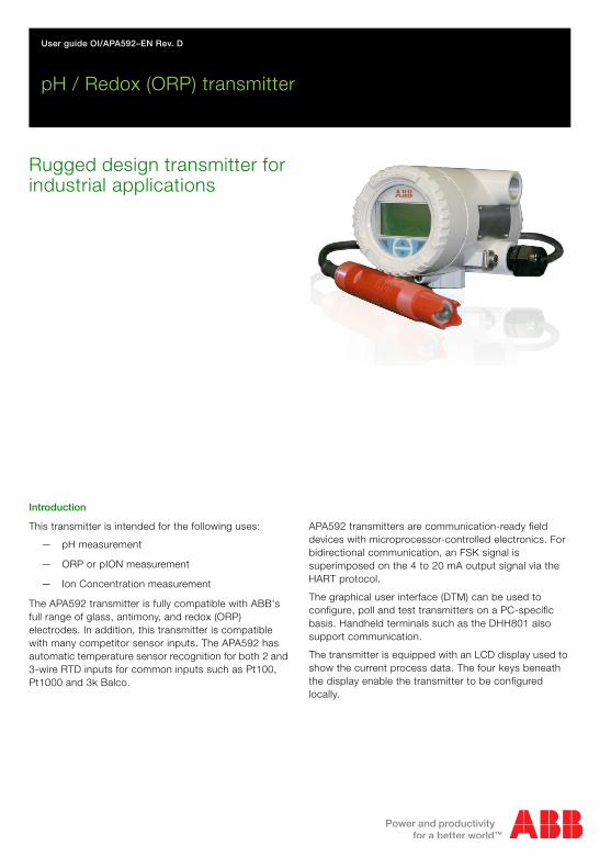
User guide OI/APA592–EN Rev. D Endura APA592 pH / Redox (ORP) transmitter Rugged design transmitter for industrial applications Introduction This transmitter is intended for the following uses: — pH measurement — ORP or pION measurement — Ion Concentration measurement The APA592 transmitter is fully compatible with ABB's full range of glass, antimony, and redox (ORP) electrodes. In addition, this transmitter is compatible with many competitor sensor inputs. The APA592 has automatic temperature sensor recognition for both 2 and 3-wire RTD inputs for common inputs such as Pt100, Pt1000 and 3k Balco. APA592 transmitters are communication-ready field devices with microprocessor-controlled electronics. For bidirectional communication, an FSK signal is superimposed on the 4 to 20 mA output signal via the HART protocol. The graphical user interface (DTM) can be used to configure, poll and test transmitters on a PC-specific basis. Handheld terminals such as the DHH801 also support communication. The transmitter is equipped with an LCD display used to show the current process data. The four keys beneath the display enable the transmitter to be configured locally.
Transcript of User guide - Endura APA592 pH / Redox (ORP) transmitter ...€¦ · Rugged design transmitter for...
User guide OI/APA592–EN Rev. D
Endura APA592pH / Redox (ORP) transmitter
Rugged design transmitter for industrial applications
Introduction
This transmitter is intended for the following uses:
— pH measurement
— ORP or pION measurement
— Ion Concentration measurement
The APA592 transmitter is fully compatible with ABB's full range of glass, antimony, and redox (ORP) electrodes. In addition, this transmitter is compatible with many competitor sensor inputs. The APA592 has automatic temperature sensor recognition for both 2 and 3-wire RTD inputs for common inputs such as Pt100, Pt1000 and 3k Balco.
APA592 transmitters are communication-ready field devices with microprocessor-controlled electronics. For bidirectional communication, an FSK signal is superimposed on the 4 to 20 mA output signal via the HART protocol.
The graphical user interface (DTM) can be used to configure, poll and test transmitters on a PC-specific basis. Handheld terminals such as the DHH801 also support communication.
The transmitter is equipped with an LCD display used to show the current process data. The four keys beneath the display enable the transmitter to be configured locally.

The CompanyWe are an established world force in the design and manufacture of instrumentation for industrial process control, flow measurement, gas and liquid analysis and environmental applications.
As a part of ABB, a world leader in process automation technology, we offer customers application expertise, service and support worldwide.
We are committed to teamwork, high quality manufacturing, advanced technology and unrivalled service and support.
The quality, accuracy and performance of the Company's products result from over 100 years experience, combined with a continuous program of innovative design and development to incorporate the latest technology.
Endura APA592pH / Redox (ORP) transmitter Contents
Contents1 Safety ............................................................................................................................................... 4
1.1 Technical Limits ....................................................................................................................... 41.2 Operator Liability ...................................................................................................................... 4
1.2.1 Operating Safety Information ......................................................................................... 41.2.2 Special Conditions of Use (FM Approval) ....................................................................... 5
1.3 Health & Safety ........................................................................................................................ 51.4 Electrical Safety – IEC / EN 61010-1 ........................................................................................ 5
1.4.1 Electrical Installation Safety Information ......................................................................... 51.5 Symbols – EN / IEC 61010-1 ................................................................................................... 61.6 Product Recycling Information ................................................................................................. 71.7 Product Disposal ..................................................................................................................... 8
1.7.1 Information on WEEE Directive 2002/96/EC (Waste Electrical and Electronic Equipment) .................................................................. 8
1.8 Returning Transmitters ............................................................................................................. 91.8.1 Transport Safety Information .......................................................................................... 9
1.9 Restriction of Hazardous Substances (RoHS) .......................................................................... 91.10 Safety Precautions ................................................................................................................... 91.11 Safety Conventions ................................................................................................................ 101.12 Safety Recommendations ...................................................................................................... 101.13 Service and Repairs ............................................................................................................... 101.14 Potential Safety Hazards ........................................................................................................ 10
2 Use in Areas Requiring Ignition Protection .................................................................................. 112.1 Approvals .............................................................................................................................. 11
2.1.1 CE Mark ...................................................................................................................... 112.1.2 Ignition Protection ....................................................................................................... 11
2.2 Ground .................................................................................................................................. 112.3 Interconnection ...................................................................................................................... 112.4 Configuration ......................................................................................................................... 112.5 Hazardous Area Relevant Information .................................................................................... 12
2.5.1 APA592-pH.A1… (Intrinsic Safety) ............................................................................... 122.5.2 APA592-pH.A2… (Flameproof Protection) ................................................................... 132.5.3 APA592-pH.A3… (Type n Non-sparking) ..................................................................... 132.5.4 APA592-pH.F1 or .C1 (Intrinsic Safety) ........................................................................ 142.5.5 APA592-pH.F2 or .C2 (Explosion-proof) ...................................................................... 152.5.6 APA592-pH.F3 or .C3 (Non-incendive) ........................................................................ 15
3 Mechanical Installation .................................................................................................................. 173.1 Hazardous Area Installation ................................................................................................... 173.2 Non-hazardous Area installation ............................................................................................ 173.3 Installation Conditions ............................................................................................................ 183.4 Dimensions ............................................................................................................................ 19
3.4.1 Transmitter-only Dimensions (Excluding Mounting Bracket) ......................................... 193.4.2 Wall-mount Transmitter Dimensions ............................................................................ 203.4.3 Pipe-mount Transmitter Dimensions ............................................................................ 213.4.4 Transmitter Label ......................................................................................................... 223.4.5 'HazLoc' Labels .......................................................................................................... 233.4.6 Aligning the Cartridge LCD Display ............................................................................. 25
OI/APA592–EN Rev. D 1
Endura APA592pH / Redox (ORP) transmitter Contents
4 Electrical Installation ......................................................................................................................264.1 Cable Glands and Plugs .........................................................................................................26
4.1.1 APA592–PH for Intrinsically Safe, Type n and Non-incendive Installations ....................264.1.2 APA592–PH Ex d / Explosion-proof Models without Cable Gland ................................26
4.2 DC Power Supply Connections ..............................................................................................284.3 Sensor Connections ...............................................................................................................294.4 Sensor Cable Color-Coded Connections ...............................................................................30
4.4.1 Standard Sensors with No Diagnostic Functions ..........................................................304.4.2 Sensors with Diagnostics Functions .............................................................................31
4.5 Integral Sensor Cable Connection ..........................................................................................324.6 Junction Box and Extension Cable Connection ......................................................................324.7 Quick-disconnect Cable Connection ......................................................................................324.8 Power Supply Requirements ..................................................................................................33
4.8.1 Standard Application ...................................................................................................334.8.2 Standard Application with HART Functionality ..............................................................344.8.3 Electrical Connection in Hazardous Area ......................................................................354.8.4 Installation in Hazardous Areas ....................................................................................36
5 Start-up and Operation ..................................................................................................................405.1 Navigating Menus and Parameters .........................................................................................405.2 Security Levels and Password Access ...................................................................................41
5.2.1 Security Permissions ....................................................................................................425.2.2 Default Passwords .......................................................................................................42
5.3 Configuration Menus Overview ............................................................................................... 43
6 Configuration ..................................................................................................................................456.1 Configuration Options ............................................................................................................456.2 Configuration DIP Switch .......................................................................................................46
7 Operator Pages and Menus ...........................................................................................................477.1 Process Display .....................................................................................................................47
7.1.1 Operator Pages ...........................................................................................................487.2 Parameter Maps ....................................................................................................................51
7.2.1 pH Parameters ............................................................................................................517.2.2 ORP or pION Parameters ............................................................................................527.2.3 Ion Concentration Parameters .....................................................................................53
7.3 Parameters ............................................................................................................................547.3.1 Easy Setup ..................................................................................................................547.3.2 Calibrate ......................................................................................................................567.3.3 Device Setup ...............................................................................................................637.3.4 Input/Output ................................................................................................................667.3.5 Display .........................................................................................................................677.3.6 Diagnostics ..................................................................................................................687.3.7 Communication ...........................................................................................................697.3.8 Service ........................................................................................................................70
8 Troubleshooting and Diagnostics .................................................................................................718.1 Diagnostic Messages .............................................................................................................728.2 Diagnosis Screens .................................................................................................................79
8.2.1 Diagnosis Overview Screen ..........................................................................................798.2.2 Diagnosis Masking .......................................................................................................808.2.3 Diagnosis Simulation ....................................................................................................81
2 OI/APA592–EN Rev. D
Endura APA592pH / Redox (ORP) transmitter Contents
9 HART Communication ................................................................................................................... 839.1 HART Device Type Codes ..................................................................................................... 839.2 HART Configuration map ....................................................................................................... 849.3 HART Universal Commands .................................................................................................. 869.4 HART Common Practice Commands .................................................................................... 88
10 Specification .................................................................................................................................. 90
11 Spares and Accessories ................................................................................................................ 95
Appendix A ......................................................................................................................................... 97A.1 Permits and Certification ........................................................................................................ 97A.2 Temperature Compensation .................................................................................................. 97A.3 Nernstian Temperature Compensation .................................................................................. 98
A.3.1 Solution Coefficient ...................................................................................................... 99
Appendix B Installation Drawings .................................................................................................... 100B.1 Drawing P0908 .................................................................................................................... 100B.2 Drawing P0909 .................................................................................................................... 101B.3 Drawing P0910 .................................................................................................................... 102B.4 Drawing P0911 .................................................................................................................... 103
Fig. B.4 Notes .................................................................................................................................... 104
OI/APA592–EN Rev. D 3
Endura APA592pH / Redox (ORP) transmitter 1 Safety
1 Safety
Information in this manual is intended only to assist our customers in the efficient operation of ourequipment. Use of this manual for any other purpose is specifically prohibited and its contents are not to bereproduced in full or part without prior approval of the Technical Publications Department.
1.1 Technical LimitsThe transmitter is designed for use exclusively within the stated values on the name plate and in thetechnical specifications (see Specifications, page 90). These must be complied with accordingly.
Do not exceed the maximum / permitted operating temperature.
Observe the housing protection system.
1.2 Operator LiabilityWhen measuring corrosive and abrasive materials, the operator must examine the resistance of all partsthat come into contact with the process being measured. ABB will assist with the selection but cannot,however, accept any liability.
Operators must strictly observe the national regulations applicable in their countries with regards toinstallation, functional tests, repairs and maintenance of electrical devices.
1.2.1 Operating Safety InformationBefore switching on, ensure that the specified environmental conditions in the Specifications section(page 90) are complied with and that the power supply voltage corresponds with the voltage of thetransmitter.
When there is a chance that safe operation is no longer possible, put the transmitter out of operation andsecure against unintended operation.
Warning.
System configuration must be carried out only by users or personnel with approved access rights(user privileges).
Read all relevant sections of this guide before configuring the system or modifying systemparameters.
Install and use this equipment as detailed in this guide. Install and use associated equipment inaccordance with the relevant national and local standards. Installation and repair must only becarried out by the manufacturer, authorized agents or persons conversant with the constructionstandards for hazardous area certified equipment.
4 OI/APA592–EN Rev. D
Endura APA592pH / Redox (ORP) transmitter 1 Safety
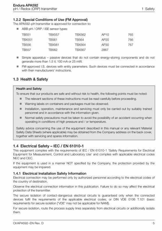
1.2.2 Special Conditions of Use (FM Approval)The APA592–pH transmitter is approved for connection to:
ABB pH / ORP / ISE sensor types:
Simple apparatus – passive devices that do not contain energy-storing components and do notgenerate more than 1.5 V, 100 mA or 25 mW.
FM-approved I.S. devices with entity parameters. Such devices must be connected in accordancewith their manufacturers' instructions.
1.3 Health & Safety
1.4 Electrical Safety – IEC / EN 61010-1This equipment complies with the requirements of IEC / EN 61010-1 'Safety Requirements for ElectricalEquipment for Measurement, Control and Laboratory Use' and complies with applicable electrical codesNEC and CEC.
If the equipment is used in a manner NOT specified by the Company, the protection provided by theequipment may be impaired.
1.4.1 Electrical Installation Safety InformationElectrical connection may be performed only by authorized personnel according to the electrical codes ofthe country of destination.
Observe the electrical connection information in this publication. Failure to do so may affect the electricalprotection of the transmitter.
The secure isolation of contact-dangerous electrical circuits is guaranteed only when the connecteddevices fulfil the requirements of the applicable electrical codes, or DIN VDE 0106 T.101 (basicrequirements for secure isolation ['VDE' may not be applicable for NAM]).
For secure isolation, route the process supply lines separately from electrical circuits or additionally isolatethem.
TB551 TBX557 TBX562 AP10 765
TBX551 TB561 TB564 AP20 766
TB556 TBX561 TBX564 AP30 767
TB557 TB562 TBX567 2867
Health and Safety
To ensure that our products are safe and without risk to health, the following points must be noted:
The relevant sections of these instructions must be read carefully before proceeding.
Warning labels on containers and packages must be observed.
Installation, operation, maintenance and servicing must only be carried out by suitably trainedpersonnel and in accordance with the information given.
Normal safety precautions must be taken to avoid the possibility of an accident occurring whenoperating in conditions of high pressure and / or temperature.
Safety advice concerning the use of the equipment described in this manual or any relevant MaterialSafety Data Sheets (where applicable) may be obtained from the Company address on the back cover,together with servicing and spares information.
OI/APA592–EN Rev. D 5
Endura APA592pH / Redox (ORP) transmitter 1 Safety
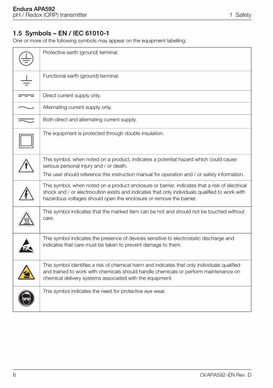
1.5 Symbols – EN / IEC 61010-1One or more of the following symbols may appear on the equipment labelling:
Protective earth (ground) terminal.
Functional earth (ground) terminal.
Direct current supply only.
Alternating current supply only.
Both direct and alternating current supply.
The equipment is protected through double insulation.
This symbol, when noted on a product, indicates a potential hazard which could cause serious personal injury and / or death.
The user should reference this instruction manual for operation and / or safety information.
This symbol, when noted on a product enclosure or barrier, indicates that a risk of electrical shock and / or electrocution exists and indicates that only individuals qualified to work with hazardous voltages should open the enclosure or remove the barrier.
This symbol indicates that the marked item can be hot and should not be touched without care.
This symbol indicates the presence of devices sensitive to electrostatic discharge and indicates that care must be taken to prevent damage to them.
This symbol identifies a risk of chemical harm and indicates that only individuals qualified and trained to work with chemicals should handle chemicals or perform maintenance on chemical delivery systems associated with the equipment.
This symbol indicates the need for protective eye wear.
6 OI/APA592–EN Rev. D
Endura APA592pH / Redox (ORP) transmitter 1 Safety
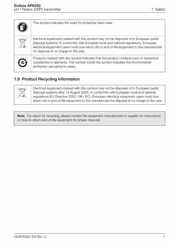
1.6 Product Recycling Information
This symbol indicates the need for protective hand wear.
Electrical equipment marked with this symbol may not be disposed of in European public disposal systems. In conformity with European local and national regulations, European electrical equipment users must now return old or end-of-life equipment to the manufacturer for disposal at no charge to the user.
Products marked with this symbol indicates that the product contains toxic or hazardous substances or elements. The number inside the symbol indicates the environmental protection use period in years.
Electrical equipment marked with this symbol may not be disposed of in European public disposal systems after 12 August 2005. In conformity with European local and national regulations (EU Directive 2002 / 96 / EC), European electrical equipment users must now return old or end-of-life equipment to the manufacturer for disposal at no charge to the user.
Note. For return for recycling, please contact the equipment manufacturer or supplier for instructions on how to return end-of-life equipment for proper disposal.
OI/APA592–EN Rev. D 7
Endura APA592pH / Redox (ORP) transmitter 1 Safety
1.7 Product DisposalABB, Inc. actively promotes environmental consciousness and has an operational management system inaccordance with DIN EN ISO 9001, EN ISO 14001 and OHSAS 18001. Our products and solutions shouldhave minimum impact on the environment and persons during manufacture, storage, transport, use anddisposal. This includes the environmentally friendly use of natural resources. Through its publications ABBconducts an open dialog with the public.
The APA592-pH transmitter is manufactured from materials that can be reused by specialized recyclingcompanies.
1.7.1 Information on WEEE Directive 2002/96/EC (Waste Electrical and Electronic Equipment)This product is not subject to the WEEE directive 2002/96/EC and relevant national laws (for example,ElektroG in Germany).
Dispose of the APA592-pH transmitter directly in a specialized recycling facility. Do not use municipalgarbage. Only privately used products may be disposed of in municipal garbage according to the WEEEdirective 2002/96/EC. Proper disposal prevents negative effects on people and the environment, andsupports the reuse of valuable raw materials.
If it is not possible to dispose of old equipment correctly, ABB Service will accept and dispose of returns fora fee.
Note. The following applies only to European customers.
ABB is committed to ensuring that the risk of any environmental damage or pollution caused by any of its products is minimized as far as possible. The European Waste Electrical and Electronic Equipment (WEEE) Directive (2002 / 96 / EC) that came into force on August 13 2005 aims to reduce the waste arising from electrical and electronic equipment; and improve the environmental performance of all those involved in the life cycle of electrical and electronic equipment.
In conformity with European local and national regulations (EU Directive 2002 / 96 / EC stated above), electrical equipment marked with the above symbol may not be disposed of in European public disposal systems after 12 August 2005.
8 OI/APA592–EN Rev. D
Endura APA592pH / Redox (ORP) transmitter 1 Safety
1.8 Returning TransmittersUse the original packaging or suitably secure packaging for returning the transmitter for repair orrecalibration. Contact the local ABB office or sales representative for return authorization number andaddress.
All transmitters returned for service or repair to ABB must be free from any hazardous materials (acids,alkali, solvents, etc.).
1.8.1 Transport Safety InformationObserve the following information:
Do not expose the transmitter to moisture during transport. Pack the transmitter accordingly.
Pack the transmitter so that it is protected from vibration during transport, e.g. through air-cushionedpackaging.
Check the transmitter for possible damage that may have occurred from improper transport. Damages intransit must be recorded on the transport documents. All claims for damages must be claimed against theshipper and before the installation.
1.9 Restriction of Hazardous Substances (RoHS)
1.10 Safety PrecautionsPlease read the entire manual before unpacking, setting up, or operating this instrument.
Pay particular attention to all warning and caution statements. Failure to do so could result in serious injuryto the operator or damage to the equipment.
To ensure the protection provided by this equipment is not impaired, do not use or install this equipment inany manner other than that which is specified in this manual.
The European Union RoHS Directive and subsequent regulations introduced in member states and other countries limits the use of six hazardous substances used in the manufacturing of electrical and electronic equipment. Currently, monitoring and control instruments do not fall within the scope of the RoHS Directive, however ABB has taken the decision to adopt the recommendations in the Directive as the target for all future product design and component purchasing.
����
OI/APA592–EN Rev. D 9
Endura APA592pH / Redox (ORP) transmitter 1 Safety
1.11 Safety Conventions
1.12 Safety RecommendationsFor safe operation, it is imperative that these service instructions be read before use and that the safetyrecommendations mentioned herein be scrupulously respected. If danger warnings are not heeded to,serious material or bodily injury could occur.
1.13 Service and RepairsOther than the serviceable items listed in Section 11, page 95, none of the transmitter's components canbe serviced by the user. Only personnel from ABB or its approved representative(s) is (are) authorized toattempt repairs to the system and only components formally approved by the manufacturer should beused. Any attempt at repairing the instrument in contravention of these principles could cause damage tothe instrument and corporal injury to the person carrying out the repair. It renders the warranty null and voidand could compromise the correct working of the instrument and the electrical integrity or the CEcompliance of the instrument.
If you have any problems with installation, starting, or using the instrument please contact the company thatsold it to you. If this is not possible, or if the results of this approach are not satisfactory, please contact themanufacturer's Customer Service.
1.14 Potential Safety HazardsThe following potential safety hazards are associated with operating the system:
Electrical (line voltage)
Use in hazardous areas
Warning. Indicates a condition which, if not met, could cause serious personal injury and / or death. Do not move beyond a warning until all conditions have been met.
If a warning sign appears on the instrument itself, refer to Precautionary Labels – product certification and Electrical Safety – EN / IEC 61010-1 for an explanation.
Caution. Indicates a condition which, if not met, could cause minor or moderate personal injury and / or damage to the equipment. Do not move beyond a caution until all conditions have been met.
Note. Indicates important information or instructions that should be considered before operating the equipment.
Note. The transmitter uses a capacitive touch display. Ensure the glass cover is kept in a clean condition to avoid contact problems caused by a dirty screen.
10 OI/APA592–EN Rev. D
Endura APA592pH / Redox (ORP) transmitter 2 Use in Areas Requiring Ignition Protection
2 Use in Areas Requiring Ignition ProtectionSpecial regulations must be observed in hazardous areas for the auxiliary power connection, signal inputs /outputs and ground connection.
2.1 Approvals
2.1.1 CE MarkThe APA592–PH including type B LCD display / configuration software meets all requirements for the CEmark in accordance with applicable EC Directives 2004/108/EC (EMC), 2006/95/EC (LVD) and 94/9/EC(ATEX).
2.1.2 Ignition ProtectionThis transmitter is FM, CSA and ATEX/IEC approved – see Section 2.5, page 12 for hazardous arearelevant information.
2.2 GroundIf for functional reasons, the intrinsically safe circuit must be grounded by connecting it to an equipotentialbonding system, it must be grounded at a single location only.
2.3 InterconnectionIf APA592-pH transmitters are operated in an intrinsically safe circuit, proof of interconnection may berequired during the installation. In general, intrinsically safe circuits require proof of interconnection.
2.4 ConfigurationAPA592-pH transmitters can be installed in hazardous areas in compliance with proof-of-interconnectionand directly in a hazardous area using approved handheld HART terminals (proof of interconnection may berequired during the installation) as well as by coupling an ignition-proof modem to the circuit outside thehazardous area.
Caution.
All parts must be installed in accordance with manufacturer information and relevant standards and regulations.
Startup and operation must be performed in accordance with ATEX User Directive 99/92/EC or BetrSichV (EN60079-14).
OI/APA592–EN Rev. D 11
Endura APA592pH / Redox (ORP) transmitter 2 Use in Areas Requiring Ignition Protection
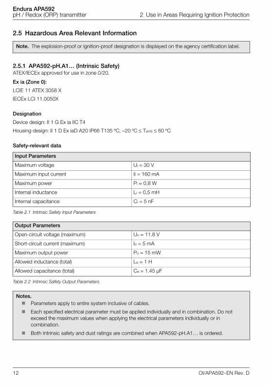
2.5 Hazardous Area Relevant Information
2.5.1 APA592-pH.A1… (Intrinsic Safety)ATEX/IECEx approved for use in zone 0/20.
Ex ia (Zone 0):
LCIE 11 ATEX 3058 X
IECEx LCI 11.0050X
Designation
Device design: II 1 G Ex ia IIC T4
Housing design: II 1 D Ex iaD A20 IP66 T135 ºC, –20 ºC Tamb 60 ºC
Safety-relevant data
Note. The explosion-proof or ignition-proof designation is displayed on the agency certification label.
Input Parameters
Maximum voltage Ui = 30 V
Maximum input current Ii = 160 mA
Maximum power Pi = 0,8 W
Internal inductance Li = 0,5 mH
Internal capacitance Ci = 5 nF
Table 2.1 Intrinsic Safety Input Parameters
Output Parameters
Open-circuit voltage (maximum) Uo = 11.8 V
Short-circuit current (maximum) Io = 5 mA
Maximum output power Po = 15 mW
Allowed inductance (total) La = 1 H
Allowed capacitance (total) Ca = 1.45 µF
Table 2.2 Intrinsic Safety Output Parameters
Notes. Parameters apply to entire system inclusive of cables.
Each specified electrical parameter must be applied individually and in combination. Do not exceed the maximum values when applying the electrical parameters individually or in combination.
Both Intrinsic safety and dust ratings are combined when APA592-pH.A1… is ordered.
12 OI/APA592–EN Rev. D
Endura APA592pH / Redox (ORP) transmitter 2 Use in Areas Requiring Ignition Protection
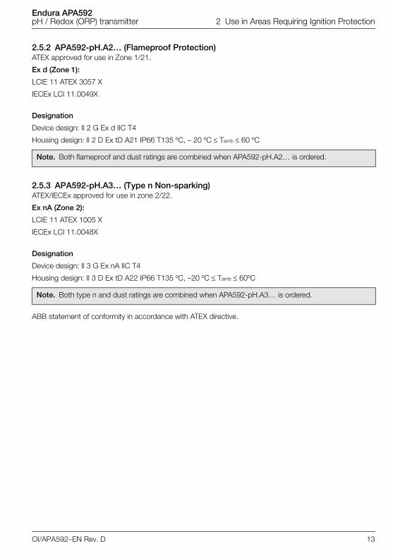
2.5.2 APA592-pH.A2… (Flameproof Protection)ATEX approved for use in Zone 1/21.
Ex d (Zone 1):
LCIE 11 ATEX 3057 X
IECEx LCI 11.0049X
Designation
Device design: II 2 G Ex d IIC T4
Housing design: II 2 D Ex tD A21 IP66 T135 ºC, – 20 ºC Tamb 60 ºC
2.5.3 APA592-pH.A3… (Type n Non-sparking)ATEX/IECEx approved for use in zone 2/22.
Ex nA (Zone 2):
LCIE 11 ATEX 1005 X
IECEx LCI 11.0048X
Designation
Device design: II 3 G Ex nA IIC T4
Housing design: II 3 D Ex tD A22 IP66 T135 ºC, –20 ºC Tamb 60ºC
ABB statement of conformity in accordance with ATEX directive.
Note. Both flameproof and dust ratings are combined when APA592-pH.A2… is ordered.
Note. Both type n and dust ratings are combined when APA592-pH.A3… is ordered.
OI/APA592–EN Rev. D 13
Endura APA592pH / Redox (ORP) transmitter 2 Use in Areas Requiring Ignition Protection
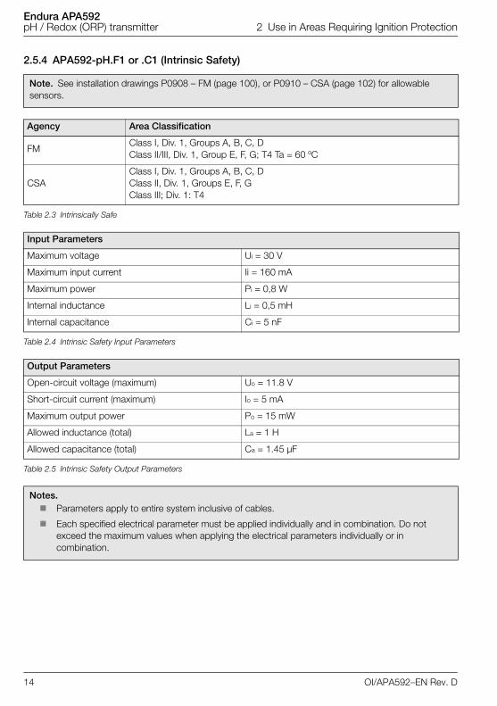
2.5.4 APA592-pH.F1 or .C1 (Intrinsic Safety)
Note. See installation drawings P0908 – FM (page 100), or P0910 – CSA (page 102) for allowable sensors.
Agency Area Classification
FMClass I, Div. 1, Groups A, B, C, DClass II/III, Div. 1, Group E, F, G; T4 Ta = 60 ºC
CSAClass I, Div. 1, Groups A, B, C, DClass II, Div. 1, Groups E, F, GClass III; Div. 1: T4
Table 2.3 Intrinsically Safe
Input Parameters
Maximum voltage Ui = 30 V
Maximum input current Ii = 160 mA
Maximum power Pi = 0,8 W
Internal inductance Li = 0,5 mH
Internal capacitance Ci = 5 nF
Table 2.4 Intrinsic Safety Input Parameters
Output Parameters
Open-circuit voltage (maximum) Uo = 11.8 V
Short-circuit current (maximum) Io = 5 mA
Maximum output power Po = 15 mW
Allowed inductance (total) La = 1 H
Allowed capacitance (total) Ca = 1.45 µF
Table 2.5 Intrinsic Safety Output Parameters
Notes. Parameters apply to entire system inclusive of cables.
Each specified electrical parameter must be applied individually and in combination. Do not exceed the maximum values when applying the electrical parameters individually or in combination.
14 OI/APA592–EN Rev. D
Endura APA592pH / Redox (ORP) transmitter 2 Use in Areas Requiring Ignition Protection
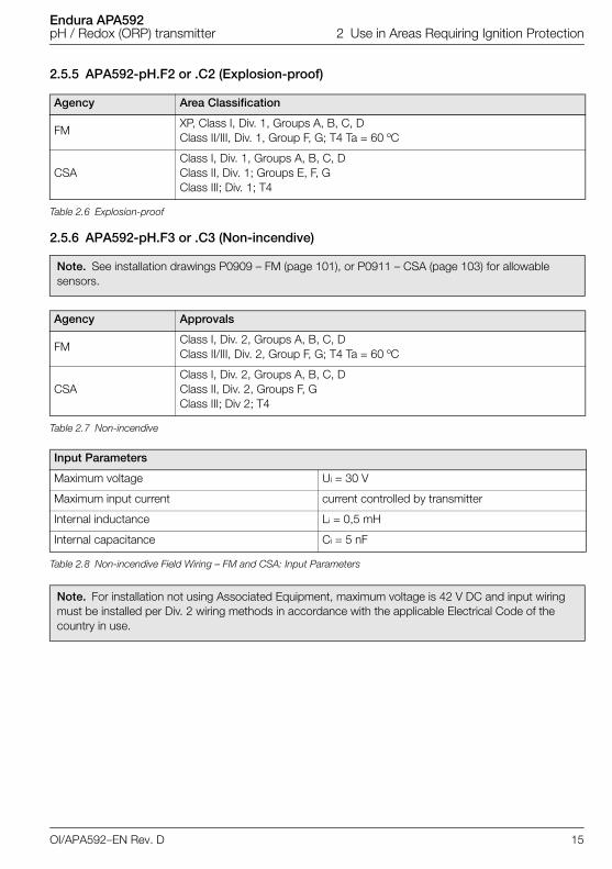
2.5.5 APA592-pH.F2 or .C2 (Explosion-proof)
2.5.6 APA592-pH.F3 or .C3 (Non-incendive)
Agency Area Classification
FMXP, Class I, Div. 1, Groups A, B, C, DClass II/III, Div. 1, Group F, G; T4 Ta = 60 ºC
CSAClass I, Div. 1, Groups A, B, C, DClass II, Div. 1; Groups E, F, GClass III; Div. 1; T4
Table 2.6 Explosion-proof
Note. See installation drawings P0909 – FM (page 101), or P0911 – CSA (page 103) for allowable sensors.
Agency Approvals
FMClass I, Div. 2, Groups A, B, C, DClass II/III, Div. 2, Group F, G; T4 Ta = 60 ºC
CSAClass I, Div. 2, Groups A, B, C, DClass II, Div. 2, Groups F, GClass III; Div 2; T4
Table 2.7 Non-incendive
Input Parameters
Maximum voltage Ui = 30 V
Maximum input current current controlled by transmitter
Internal inductance Li = 0,5 mH
Internal capacitance Ci = 5 nF
Table 2.8 Non-incendive Field Wiring – FM and CSA: Input Parameters
Note. For installation not using Associated Equipment, maximum voltage is 42 V DC and input wiring must be installed per Div. 2 wiring methods in accordance with the applicable Electrical Code of the country in use.
OI/APA592–EN Rev. D 15
Endura APA592pH / Redox (ORP) transmitter 2 Use in Areas Requiring Ignition Protection
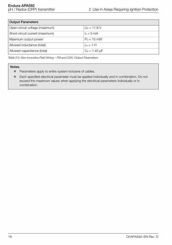
Output Parameters
Open-circuit voltage (maximum) Uo = 11.8 V
Short-circuit current (maximum) Io = 5 mA
Maximum output power Po = 15 mW
Allowed inductance (total) La = 1 H
Allowed capacitance (total) Ca = 1.45 µF
Table 2.9 Non-incendive Field Wiring – FM and CSA: Output Parameters
Notes. Parameters apply to entire system inclusive of cables.
Each specified electrical parameter must be applied individually and in combination. Do not exceed the maximum values when applying the electrical parameters individually or in combination.
16 OI/APA592–EN Rev. D
Endura APA592pH / Redox (ORP) transmitter 3 Mechanical Installation
3 Mechanical Installation
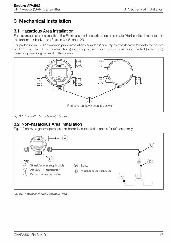
3.1 Hazardous Area InstallationFor hazardous area designation, the Ex installation is described on a separate 'HazLoc' label mounted onthe transmitter body – see Section 3.4.5, page 23.
For protection in Ex d / explosion-proof installations, turn the 2 security screws (located beneath the coverson front and rear of the housing body) until they prevent both covers from being rotated (unscrewed)therefore preventing removal of the covers.
3.2 Non-hazardous Area installationFig. 3.2 shows a general purpose non-hazardous installation and is for reference only.
Fig. 3.1 Transmitter Cover Security Screws
Fig. 3.2 Installation in Non-Hazardous Area
Front and rear cover security screws
Key:
A Signal / power supply cable
B APA592–PH transmitter
C Sensor connection cable
D Sensor
E Process to be measured
OI/APA592–EN Rev. D 17
Endura APA592pH / Redox (ORP) transmitter 3 Mechanical Installation
3.3 Installation ConditionsEnsure the following installation conditions are met:
1. Install the transmitter with consideration to ambient conditions.
2. Locate the transmitter in a position where the temperature and humidity specifications are notexceeded and ensure the transmitter is protected from direct sunlight, rain, snow and hail.
3. Ensure the transmitter operating temperature is within the range –20 to 60 °C (–4 to 140 °F).
4. Select a location away from strong electrical and magnetic fields.
18 OI/APA592–EN Rev. D
Endura APA592pH / Redox (ORP) transmitter 3 Mechanical Installation
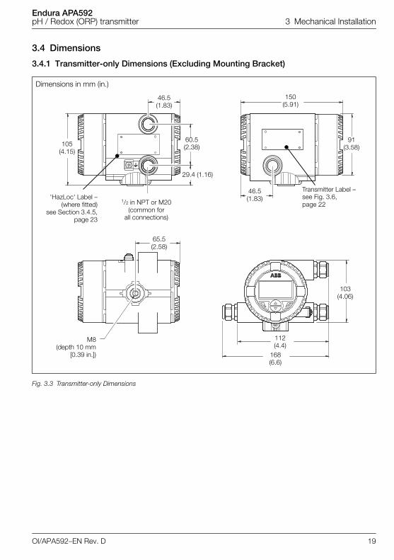
3.4 Dimensions
3.4.1 Transmitter-only Dimensions (Excluding Mounting Bracket)
Dimensions in mm (in.)
Fig. 3.3 Transmitter-only Dimensions
Transmitter Label – see Fig. 3.6, page 22
1/2 in NPT or M20(common for
all connections)
M8(depth 10 mm
[0.39 in.])
46.5 (1.83)
150(5.91)
91 (3.58)
60.5 (2.38)
29.4 (1.16)
105 (4.15)
46.5 (1.83)
65.5 (2.58)
103 (4.06)
112 (4.4)
168 (6.6)
'HazLoc' Label –(where fitted)
see Section 3.4.5,page 23
OI/APA592–EN Rev. D 19
Endura APA592pH / Redox (ORP) transmitter 3 Mechanical Installation
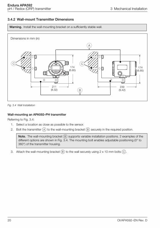
3.4.2 Wall-mount Transmitter Dimensions
Wall-mounting an APA592–PH transmitter
Referring to Fig. 3.4:
1. Select a location as close as possible to the sensor.
2. Bolt the transmitter A to the wall-mounting bracket B securely in the required position.
3. Attach the wall-mounting bracket B to the wall securely using 2 x 10 mm bolts C.
Warning. Install the wall-mounting bracket on a sufficiently stable wall.
Dimensions in mm (in)
Fig. 3.4 Wall Installation
Note. The wall-mounting bracket B supports variable installation positions. 2 examples of the different options are shown in Fig. 3.4. The mounting bolt enables adjustable positioning (0° to 360°) of the transmitter housing.
CC
A
B211
(8.32)239
(9.42)
174 (6.85)
174 (6.85)
20 OI/APA592–EN Rev. D
Endura APA592pH / Redox (ORP) transmitter 3 Mechanical Installation
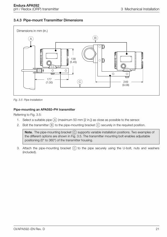
3.4.3 Pipe-mount Transmitter Dimensions
Pipe-mounting an APA592–PH transmitter
Referring to Fig. 3.5:
1. Select a suitable pipe A (maximum 50 mm [2 in.]) as close as possible to the sensor.
2. Bolt the transmitter B to the pipe-mounting bracket C securely in the required position.
3. Attach the pipe-mounting bracket C to the pipe securely using the U-bolt, nuts and washers(included).
Dimensions in mm (in.)
Fig. 3.5 Pipe Installation
Note. The pipe-mounting bracket C supports variable installation positions. Two examples of the different options are shown in Fig. 3.5. The transmitter mounting bolt enables adjustable positioning (0° to 360°) of the transmitter housing.
�
��
177 (7.00) 249
(9.08)
138 (5.45)
OI/APA592–EN Rev. D 21
Endura APA592pH / Redox (ORP) transmitter 3 Mechanical Installation
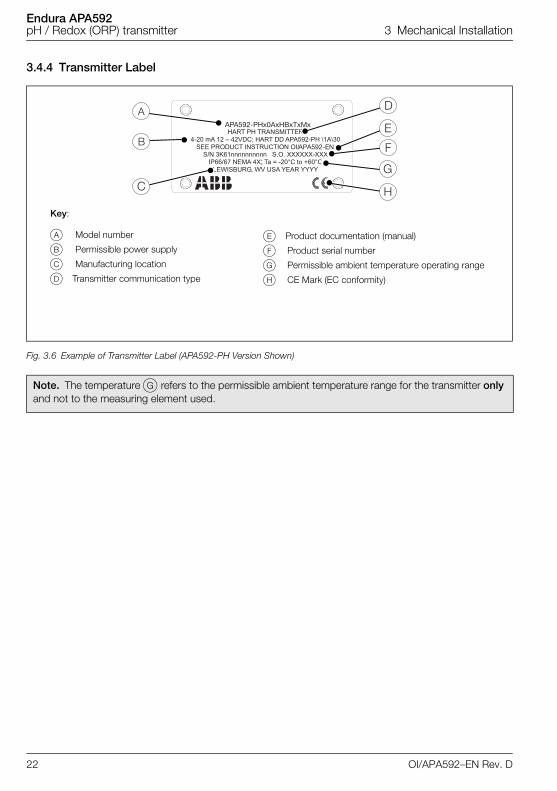
3.4.4 Transmitter Label
Fig. 3.6 Example of Transmitter Label (APA592-PH Version Shown)
Note. The temperature G refers to the permissible ambient temperature range for the transmitter only and not to the measuring element used.
;
APA592-PHx0AxHBxTxM
APA592-EN
x
Key:
A Model number
B Permissible power supply
C Manufacturing location
D Transmitter communication type
E Product documentation (manual)
F Product serial number
G Permissible ambient temperature operating range
H CE Mark (EC conformity)
22 OI/APA592–EN Rev. D
Endura APA592pH / Redox (ORP) transmitter 3 Mechanical Installation
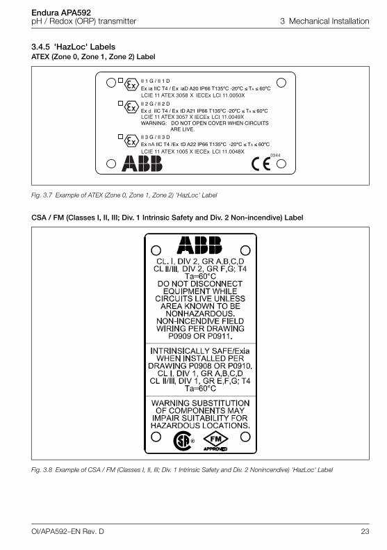
3.4.5 'HazLoc' LabelsATEX (Zone 0, Zone 1, Zone 2) Label
CSA / FM (Classes I, II, III; Div. 1 Intrinsic Safety and Div. 2 Non-incendive) Label
Fig. 3.7 Example of ATEX (Zone 0, Zone 1, Zone 2) 'HazLoc' Label
Fig. 3.8 Example of CSA / FM (Classes I, II, III; Div. 1 Intrinsic Safety and Div. 2 Nonincendive) 'HazLoc' Label
0344
ii
nA
d
OI/APA592–EN Rev. D 23
Endura APA592pH / Redox (ORP) transmitter 3 Mechanical Installation
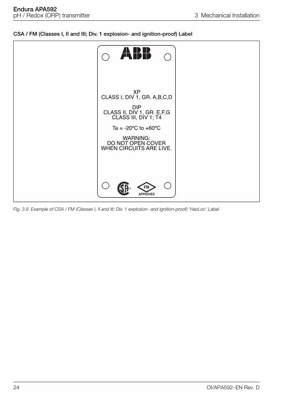
CSA / FM (Classes I, II and III; Div. 1 explosion- and ignition-proof) Label
Fig. 3.9 Example of CSA / FM (Classes I, II and III; Div. 1 explosion- and ignition-proof) 'HazLoc' Label
®�
24 OI/APA592–EN Rev. D
Endura APA592pH / Redox (ORP) transmitter 3 Mechanical Installation
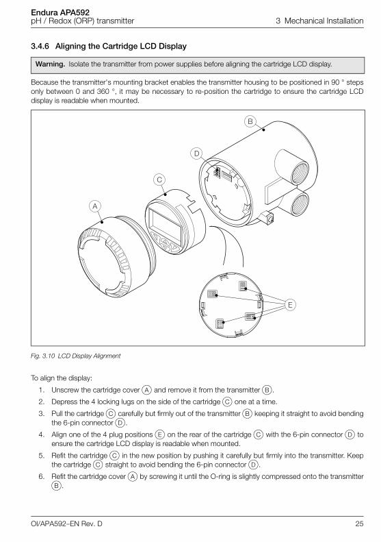
3.4.6 Aligning the Cartridge LCD Display
Because the transmitter's mounting bracket enables the transmitter housing to be positioned in 90 ° stepsonly between 0 and 360 °, it may be necessary to re-position the cartridge to ensure the cartridge LCDdisplay is readable when mounted.
To align the display:
1. Unscrew the cartridge cover A and remove it from the transmitter B.
2. Depress the 4 locking lugs on the side of the cartridge C one at a time.
3. Pull the cartridge C carefully but firmly out of the transmitter B keeping it straight to avoid bendingthe 6-pin connector D.
4. Align one of the 4 plug positions E on the rear of the cartridge C with the 6-pin connector D toensure the cartridge LCD display is readable when mounted.
5. Refit the cartridge C in the new position by pushing it carefully but firmly into the transmitter. Keepthe cartridge C straight to avoid bending the 6-pin connector D.
6. Refit the cartridge cover A by screwing it until the O-ring is slightly compressed onto the transmitterB.
Warning. Isolate the transmitter from power supplies before aligning the cartridge LCD display.
Fig. 3.10 LCD Display Alignment
�
�
�
�
OI/APA592–EN Rev. D 25
Endura APA592pH / Redox (ORP) transmitter 4 Electrical Installation
4 Electrical Installation
4.1 Cable Glands and Plugs
4.1.1 APA592–PH for Intrinsically Safe, Type n and Non-incendive InstallationsNon-Ex d transmitters are supplied with a nylon conduit plug and cable gland. The cable gland is sized toprovide a tight seal around the sensor cable.
If a customer-supplied cable gland and plug is used, the cable diameter for the cable gland used mustcomply with the requirements for IP/NEMA 4X protection. This must be checked during installation.
4.1.2 APA592–PH Ex d / Explosion-proof Models without Cable GlandAPA592–PH Ex d / explosion-proof rated transmitters are supplied with a standard 316 stainless steel ratedplug.
Hazardous area 316 stainless steel 1/2 in. NPT or M20 cable glands must be ordered as an accessorybased on the hazardous area installation requirements.
Warning.
Observe all local instructions and regulations governing electrical installation. Ensure the power supply and / or bus connections are switched off before making connections.
Use a maximum of 12 SWG (10 AWG) wire for connection of this transmitter.
Ensure connection to protective earth.
Do not apply power until fully installed.
The transmitter is not fitted with a switch and does not have an overvoltage protection device, lightning protection or voltage separation capacity therefore these must be provided on the plant side.
Power supplies and signals are routed in the same line and must be implemented as SELV or PELV circuits according to requirements (standard version). In the ignition-proof version, the guidelines regarding the ignition-proof requirements must be adhered to.
Ensure the existing power supply corresponds with the specifications on the name plate and the technical specifications – see Section 10, page 90.
Use only signal cable wires with tinned or wire end sleeves.
Note. For ATEX installations, an approved ATEX Ex d cable gland must be used according to IEC/EN 60079-1. For FM and CSA installations, an approved Ex d cable gland must be used.
26 OI/APA592–EN Rev. D
Endura APA592pH / Redox (ORP) transmitter 4 Electrical Installation
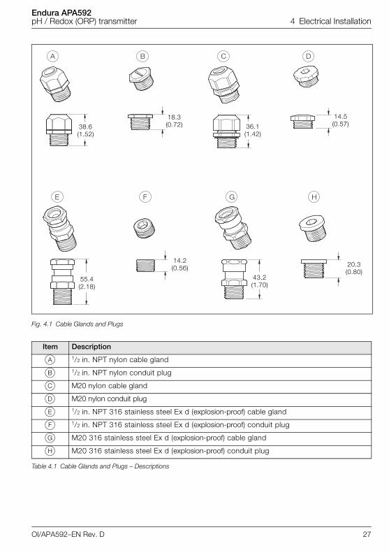
Fig. 4.1 Cable Glands and Plugs
Item Description
A 1/2 in. NPT nylon cable gland
B 1/2 in. NPT nylon conduit plug
C M20 nylon cable gland
D M20 nylon conduit plug
E 1/2 in. NPT 316 stainless steel Ex d (explosion-proof) cable gland
F 1/2 in. NPT 316 stainless steel Ex d (explosion-proof) conduit plug
G M20 316 stainless steel Ex d (explosion-proof) cable gland
H M20 316 stainless steel Ex d (explosion-proof) conduit plug
Table 4.1 Cable Glands and Plugs – Descriptions
� � �
� � �
55.4(2.18)
14.2(0.56)
43.2(1.70)
20.3(0.80)
38.6(1.52)
36.1(1.42)
18.3(0.72)
14.5(0.57)
OI/APA592–EN Rev. D 27
Endura APA592pH / Redox (ORP) transmitter 4 Electrical Installation
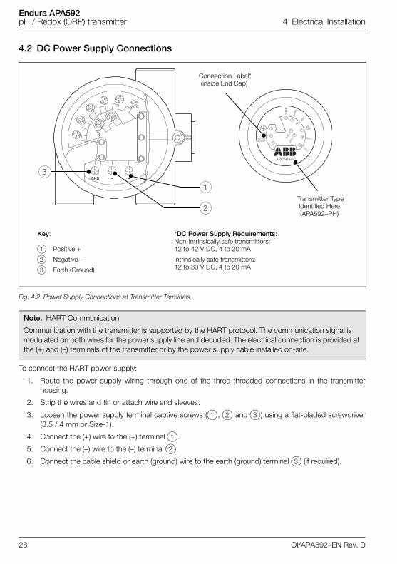
4.2 DC Power Supply Connections
To connect the HART power supply:
1. Route the power supply wiring through one of the three threaded connections in the transmitterhousing.
2. Strip the wires and tin or attach wire end sleeves.
3. Loosen the power supply terminal captive screws (1, 2 and 3) using a flat-bladed screwdriver(3.5 / 4 mm or Size-1).
4. Connect the (+) wire to the (+) terminal 1.
5. Connect the (–) wire to the (–) terminal 2.
6. Connect the cable shield or earth (ground) wire to the earth (ground) terminal 3 (if required).
Fig. 4.2 Power Supply Connections at Transmitter Terminals
Note. HART Communication
Communication with the transmitter is supported by the HART protocol. The communication signal is modulated on both wires for the power supply line and decoded. The electrical connection is provided at the (+) and (–) terminals of the transmitter or by the power supply cable installed on-site.
��� � ��
�
�
�
�
�
��
�
�
�
�
��
���
�������������
���������
�� ��
�!�
���
�"� #
�!�
�!�
��
�
��#
��
Connection Label* (inside End Cap)
Key:
1 Positive +
2 Negative –
3 Earth (Ground)
*DC Power Supply Requirements: Non-Intrinsically safe transmitters: 12 to 42 V DC, 4 to 20 mA
Intrinsically safe transmitters: 12 to 30 V DC, 4 to 20 mA
Transmitter Type Identified Here(APA592–PH)
28 OI/APA592–EN Rev. D
Endura APA592pH / Redox (ORP) transmitter 4 Electrical Installation
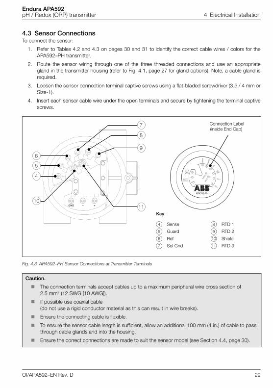
4.3 Sensor ConnectionsTo connect the sensor:
1. Refer to Tables 4.2 and 4.3 on pages 30 and 31 to identify the correct cable wires / colors for theAPA592–PH transmitter.
2. Route the sensor wiring through one of the three threaded connections and use an appropriategland in the transmitter housing (refer to Fig. 4.1, page 27 for gland options). Note, a cable gland isrequired.
3. Loosen the sensor connection terminal captive screws using a flat-bladed screwdriver (3.5 / 4 mm orSize-1).
4. Insert each sensor cable wire under the open terminals and secure by tightening the terminal captivescrews.
Fig. 4.3 APA592–PH Sensor Connections at Transmitter Terminals
Caution.
The connection terminals accept cables up to a maximum peripheral wire cross section of 2.5 mm2 (12 SWG [10 AWG]).
If possible use coaxial cable (do not use a rigid conductor material as this can result in wire breaks).
Ensure the connecting cable is flexible.
To ensure the sensor cable length is sufficient, allow an additional 100 mm (4 in.) of cable to pass through cable glands and into the housing.
Ensure the correct connections are made to suit the sensor model (see Section 4.4, page 30).
10
Key:
4 Sense
5 Guard
6 Ref
7 Sol Gnd
8 RTD 1
9 RTD 2
0 Shield
k RTD 3
Connection Label (inside End Cap)
OI/APA592–EN Rev. D 29
Endura APA592pH / Redox (ORP) transmitter 4 Electrical Installation
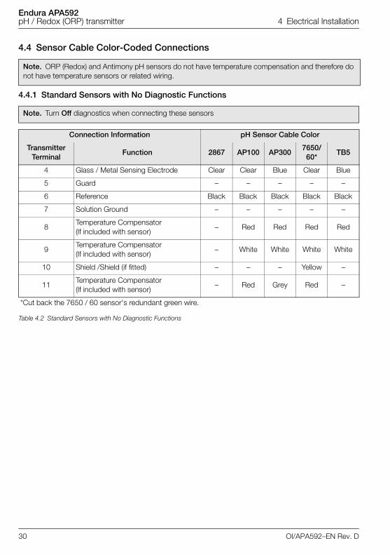
4.4 Sensor Cable Color-Coded Connections
4.4.1 Standard Sensors with No Diagnostic Functions
Note. ORP (Redox) and Antimony pH sensors do not have temperature compensation and therefore do not have temperature sensors or related wiring.
Note. Turn Off diagnostics when connecting these sensors
Connection Information pH Sensor Cable Color
Transmitter Terminal
Function 2867 AP100 AP3007650/60*
TB5
4 Glass / Metal Sensing Electrode Clear Clear Blue Clear Blue
5 Guard – – – – –
6 Reference Black Black Black Black Black
7 Solution Ground – – – – –
8Temperature Compensator (If included with sensor)
– Red Red Red Red
9Temperature Compensator (If included with sensor)
– White White White White
10 Shield /Shield (if fitted) – – – Yellow –
11Temperature Compensator (If included with sensor)
– Red Grey Red –
*Cut back the 7650 / 60 sensor's redundant green wire.
Table 4.2 Standard Sensors with No Diagnostic Functions
30 OI/APA592–EN Rev. D
Endura APA592pH / Redox (ORP) transmitter 4 Electrical Installation
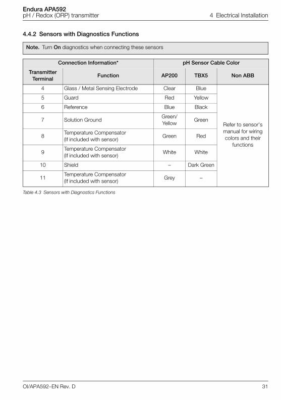
4.4.2 Sensors with Diagnostics Functions
Note. Turn On diagnostics when connecting these sensors
Connection Information* pH Sensor Cable Color
Transmitter Terminal
Function AP200 TBX5 Non ABB
4 Glass / Metal Sensing Electrode Clear Blue
Refer to sensor's manual for wiring colors and their
functions
5 Guard Red Yellow
6 Reference Blue Black
7 Solution GroundGreen/Yellow
Green
8Temperature Compensator (If included with sensor)
Green Red
9Temperature Compensator (If included with sensor)
White White
10 Shield – Dark Green
11Temperature Compensator (If included with sensor)
Grey –
Table 4.3 Sensors with Diagnostics Functions
OI/APA592–EN Rev. D 31
Endura APA592pH / Redox (ORP) transmitter 4 Electrical Installation
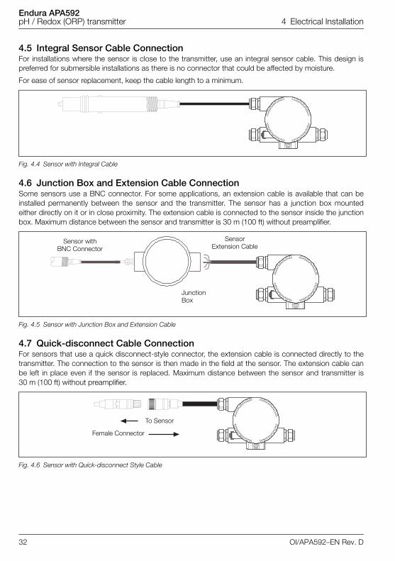
4.5 Integral Sensor Cable ConnectionFor installations where the sensor is close to the transmitter, use an integral sensor cable. This design ispreferred for submersible installations as there is no connector that could be affected by moisture.
For ease of sensor replacement, keep the cable length to a minimum.
4.6 Junction Box and Extension Cable ConnectionSome sensors use a BNC connector. For some applications, an extension cable is available that can beinstalled permanently between the sensor and the transmitter. The sensor has a junction box mountedeither directly on it or in close proximity. The extension cable is connected to the sensor inside the junctionbox. Maximum distance between the sensor and transmitter is 30 m (100 ft) without preamplifier.
4.7 Quick-disconnect Cable ConnectionFor sensors that use a quick disconnect-style connector, the extension cable is connected directly to thetransmitter. The connection to the sensor is then made in the field at the sensor. The extension cable canbe left in place even if the sensor is replaced. Maximum distance between the sensor and transmitter is30 m (100 ft) without preamplifier.
Fig. 4.4 Sensor with Integral Cable
Fig. 4.5 Sensor with Junction Box and Extension Cable
Fig. 4.6 Sensor with Quick-disconnect Style Cable
Sensor with BNC Connector
Sensor Extension Cable
Junction Box
Female Connector
To Sensor
32 OI/APA592–EN Rev. D
Endura APA592pH / Redox (ORP) transmitter 4 Electrical Installation
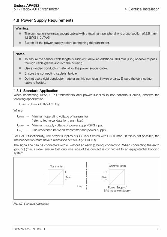
4.8 Power Supply Requirements
4.8.1 Standard ApplicationWhen connecting APA592–PH transmitters and power supplies in non-hazardous areas, observe thefollowing specification:
USmin UMmin + 0.022A x RLtg
Where:
For HART functionality, use power supplies or SPS input cards with HART mark. If this is not possible, theinterconnection must have a resistance of 250 (< 1100 ).
The signal line can be connected with or without an earth (ground) connection. When connecting the earth(ground) (minus side), ensure that only one side of the contact is connected to an equipotential bondingsystem.
Warning.
The connection terminals accept cables with a maximum peripheral wire cross-section of 2.5 mm2 12 SWG (10 AWG).
Switch off the power supply before connecting the transmitter.
Notes.
To ensure the sensor cable length is sufficient, allow an additional 100 mm (4 in.) of cable to pass through cable glands and into the housing.
Use stranded conductor material for the power supply cable.
Ensure the connecting cable is flexible.
Do not use a rigid conductor material as this can result in wire breaks. Ensure the connecting cable is flexible.
UMmin – Minimum operating voltage of transmitter (refer to technical data for transmitter)
USmin – Minimum supply voltage of power supply/SPS input
RLtg – Line resistance between transmitter and power supply
Fig. 4.7 Standard Application
�
�
�
�
Transmitter
Power Supply / SPS Input with Supply
UMmin USmin
RLtg
Control Room
OI/APA592–EN Rev. D 33
Endura APA592pH / Redox (ORP) transmitter 4 Electrical Installation
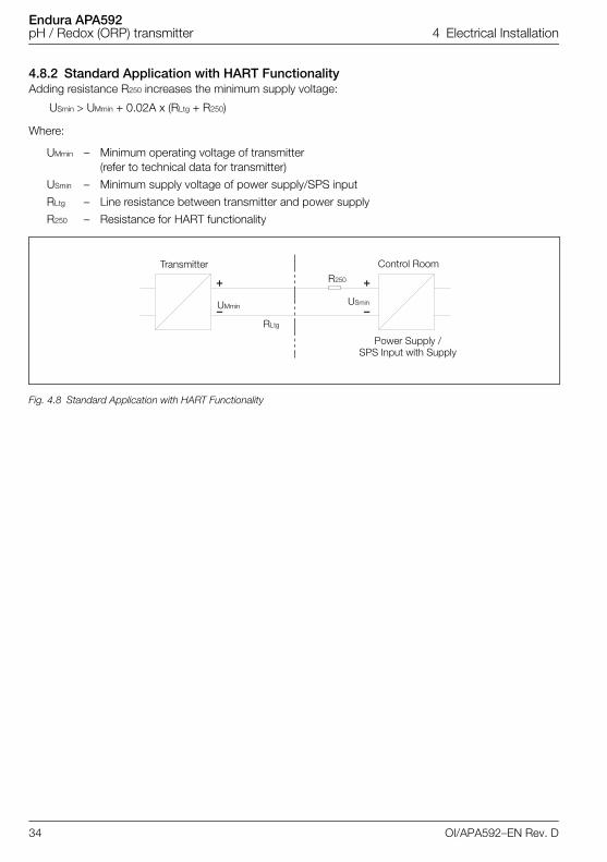
4.8.2 Standard Application with HART FunctionalityAdding resistance R250 increases the minimum supply voltage:
USmin UMmin + 0.02A x (RLtg + R250)
Where:
UMmin – Minimum operating voltage of transmitter (refer to technical data for transmitter)
USmin – Minimum supply voltage of power supply/SPS input
RLtg – Line resistance between transmitter and power supply
R250 – Resistance for HART functionality
Fig. 4.8 Standard Application with HART Functionality
�
�
�
�
Transmitter
Power Supply /SPS Input with Supply
UMmin USmin
RLtg
R250
Control Room
34 OI/APA592–EN Rev. D

Endura APA592pH / Redox (ORP) transmitter 4 Electrical Installation
4.8.3 Electrical Connection in Hazardous AreaSpecial interconnections are required for use in hazardous areas depending on the safety requirements.
Intrinsic safety
The power supply SPS inputs must have corresponding input protection circuits available to eliminate sparkhazards. An interconnection inspection must be performed. For proof of intrinsic safety, the electrical limitvalues must be used as the basis for the prototype test certificates of the transmitters, including thecapacitance and inductance values of the wires. Proof of intrinsic safety is granted if the conditions in Table4.4 are fulfilled.
Caution. Refer to Section 2, page 11 and Section 10, page 90 for hazardous area risk requirements.
APA592–PH(Intrinsically Safe Transmitter)
Power Supply/SPS Input (Related Apparatus)
Ui Uo
Ii Io
Pi Po
Li + Lc (cable) Lo
Ci + Cc (cable) Co
Table 4.4 Intrinsic Safety Conditions
Fig. 4.9 Hazardous Area Risk Application
�
�
�
�
Transmitter Power Supply SPS Input
Field (Ex Area)
Control Room (Secure Area)
OI/APA592–EN Rev. D 35
Endura APA592pH / Redox (ORP) transmitter 4 Electrical Installation
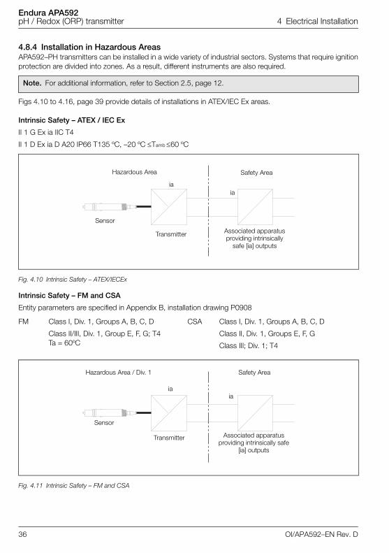
4.8.4 Installation in Hazardous AreasAPA592–PH transmitters can be installed in a wide variety of industrial sectors. Systems that require ignitionprotection are divided into zones. As a result, different instruments are also required.
Figs 4.10 to 4.16, page 39 provide details of installations in ATEX/IEC Ex areas.
Intrinsic Safety – ATEX / IEC Ex
II 1 G Ex ia IIC T4
II 1 D Ex ia D A20 IP66 T135 ºC, –20 ºC Tamb 60 ºC
Intrinsic Safety – FM and CSA
Entity parameters are specified in Appendix B, installation drawing P0908
Note. For additional information, refer to Section 2.5, page 12.
Fig. 4.10 Intrinsic Safety – ATEX/IECEx
FM Class I, Div. 1, Groups A, B, C, D
Class II/III, Div. 1, Group E, F, G; T4 Ta = 60ºC
CSA Class I, Div. 1, Groups A, B, C, D
Class II, Div. 1, Groups E, F, G
Class III; Div. 1; T4
Fig. 4.11 Intrinsic Safety – FM and CSA
Hazardous Area Safety Area
Sensor
Associated apparatus providing intrinsically
safe [ia] outputs
Transmitter
iaia
Hazardous Area / Div. 1 Safety Area
Sensor
Associated apparatus providing intrinsically safe
[ia] outputs
Transmitter
iaia
36 OI/APA592–EN Rev. D
Endura APA592pH / Redox (ORP) transmitter 4 Electrical Installation
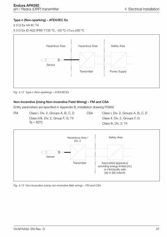
Type n (Non-sparking) – ATEX/IEC Ex
II 3 G Ex nA IIC T4
II 3 D Ex tD A22 IP66 T135 ºC, –20 ºCTamb 60 ºC
Non-Incendive (Using Non-incendive Field Wiring) – FM and CSA
Entity parameters are specified in Appendix B, installation drawing P0909
Fig. 4.12 Type n (Non-sparking) – ATEX/IECEx
FM Class I, Div. 2, Groups A, B, C, D
Class II/III, Div. 2, Group F, G; T4 Ta = 60ºC
CSA Class I, Div. 2, Groups A, B, C, D
Class II, Div. 2, Groups F, G
Class III, Div. 2; T4
Fig. 4.13 Non-Incendive (using non-incendive field wiring) – FM and CSA
Safety Area
Power Supply
Hazardous Area
Sensor
Transmitter
Hazardous Area
Hazardous Area / Div. 2
Safety Area
Sensor
Associated apparatus providing energy limited [nL]
or intrinsically safe [ia] or [ib] outputs
Transmitter
OI/APA592–EN Rev. D 37
Endura APA592pH / Redox (ORP) transmitter 4 Electrical Installation
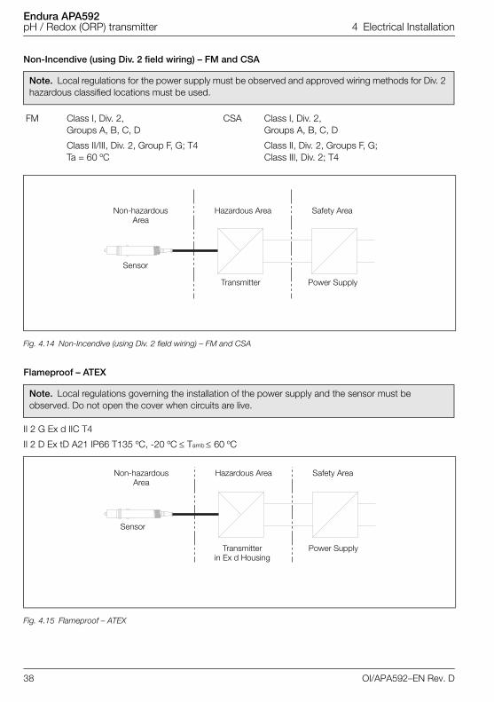
Non-Incendive (using Div. 2 field wiring) – FM and CSA
Flameproof – ATEX
II 2 G Ex d IIC T4
II 2 D Ex tD A21 IP66 T135 ºC, -20 ºC Tamb 60 ºC
Note. Local regulations for the power supply must be observed and approved wiring methods for Div. 2 hazardous classified locations must be used.
FM Class I, Div. 2, Groups A, B, C, D
Class II/III, Div. 2, Group F, G; T4 Ta = 60 ºC
CSA Class I, Div. 2, Groups A, B, C, D
Class II, Div. 2, Groups F, G; Class III, Div. 2; T4
Fig. 4.14 Non-Incendive (using Div. 2 field wiring) – FM and CSA
Note. Local regulations governing the installation of the power supply and the sensor must be observed. Do not open the cover when circuits are live.
Fig. 4.15 Flameproof – ATEX
Safety Area
Power Supply
Non-hazardous Area
Sensor
Transmitter
Hazardous Area
Safety Area
Power Supply
Non-hazardous Area
Sensor
Transmitter in Ex d Housing
Hazardous Area
38 OI/APA592–EN Rev. D
Endura APA592pH / Redox (ORP) transmitter 4 Electrical Installation
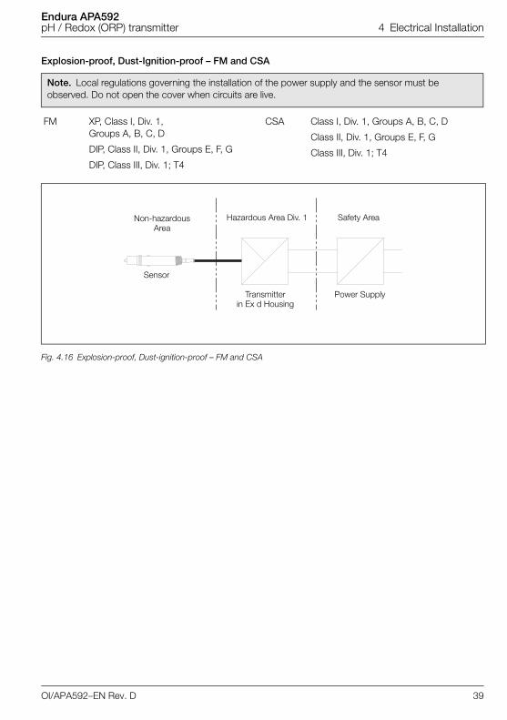
Explosion-proof, Dust-Ignition-proof – FM and CSA
Note. Local regulations governing the installation of the power supply and the sensor must be observed. Do not open the cover when circuits are live.
FM XP, Class I, Div. 1, Groups A, B, C, D
DIP, Class II, Div. 1, Groups E, F, G
DIP, Class III, Div. 1; T4
CSA Class I, Div. 1, Groups A, B, C, D
Class II, Div. 1, Groups E, F, G
Class III, Div. 1; T4
Fig. 4.16 Explosion-proof, Dust-ignition-proof – FM and CSA
Safety Area
Power Supply
Non-hazardous Area
Sensor
Transmitter in Ex d Housing
Hazardous Area Div. 1
OI/APA592–EN Rev. D 39
Endura APA592pH / Redox (ORP) transmitter 5 Start-up and Operation
5 Start-up and Operation
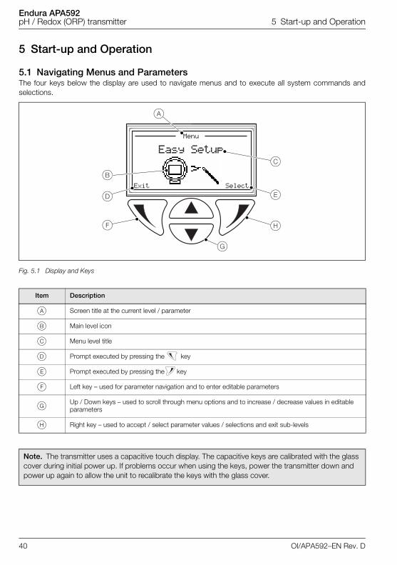
5.1 Navigating Menus and ParametersThe four keys below the display are used to navigate menus and to execute all system commands andselections.
Fig. 5.1 Display and Keys
Item Description
A Screen title at the current level / parameter
B Main level icon
C Menu level title
D Prompt executed by pressing the key
E Prompt executed by pressing the key
F Left key – used for parameter navigation and to enter editable parameters
G Up / Down keys – used to scroll through menu options and to increase / decrease values in editable parameters
H Right key – used to accept / select parameter values / selections and exit sub-levels
Note. The transmitter uses a capacitive touch display. The capacitive keys are calibrated with the glass cover during initial power up. If problems occur when using the keys, power the transmitter down and power up again to allow the unit to recalibrate the keys with the glass cover.
���� �����
���
� ��������
�
�
� �
�
�
�
40 OI/APA592–EN Rev. D
Endura APA592pH / Redox (ORP) transmitter 5 Start-up and Operation
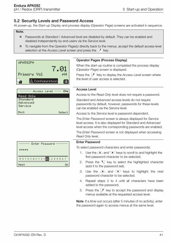
5.2 Security Levels and Password AccessAt power-up, the Start-up Display and process display (Operator Page) screens are activated in sequence.
Note.
Passwords at Standard / Advanced level are disabled by default. They can be enabled and disabled independently by end-users via the Service level.
To navigate from the Operator Page(s) directly back to the menus, accept the default access levelselection at the Access Level screen and press the key.
Operator Pages (Process Display)
When the start-up routine is completed the process display (Operator Page) screen is displayed.
Press the key to display the Access Level screen where the level of user access is selected.
Access Level
Access to the Read Only level does not require a password.
Standard and Advanced access levels do not require passwords by default, however, passwords for these levels can be enabled via the Service level.
Access to the Service level is password-dependent.
The Enter Password screen is always displayed for Service level access. It is also displayed for Standard and Advanced level access when the corresponding passwords are enabled.
The Enter Password screen is not displayed when accessing Read Only level.
Enter Password
To select password characters and enter passwords:
1. Use the and keys to scroll to and highlight the first password character to be selected.
2. Press the key to select the highlighted character(add it to the password set).
3. Use the and keys to highlight the nextpassword character to be selected.
4. Repeat steps 2 to 4 until all characters have beenadded to the password.
5. Press the key to accept the password and displaymenus available at the requested access level.
Note. If a time-out occurs (after 5 minutes of no activity), enter the password again to access menus at the same level.
1
APA592PH
7.01pHPrimary Val
Configuration
Access Level
Read OnlyStandard AdvancedService
Back Select
Next OK
Enter Password
OI/APA592–EN Rev. D 41
Endura APA592pH / Redox (ORP) transmitter 5 Start-up and Operation
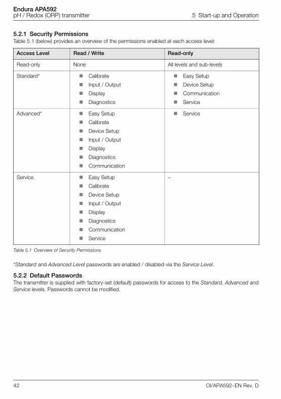
5.2.1 Security PermissionsTable 5.1 (below) provides an overview of the permissions enabled at each access level:
*Standard and Advanced Level passwords are enabled / disabled via the Service Level.
5.2.2 Default PasswordsThe transmitter is supplied with factory-set (default) passwords for access to the Standard, Advanced andService levels. Passwords cannot be modified.
Access Level Read / Write Read-only
Read-only None All levels and sub-levels
Standard* Calibrate
Input / Output
Display
Diagnostics
Easy Setup
Device Setup
Communication
Service
Advanced* Easy Setup
Calibrate
Device Setup
Input / Output
Display
Diagnostics
Communication
Service
Service Easy Setup
Calibrate
Device Setup
Input / Output
Display
Diagnostics
Communication
Service
–
Table 5.1 Overview of Security Permissions
42 OI/APA592–EN Rev. D
Endura APA592pH / Redox (ORP) transmitter 5 Start-up and Operation
5.3 Configuration Menus Overview
To access menus from an Operator Page, press the key (beneath the icon) and select the requiredlevel of access (enter a user password if necessary). To scroll between menus, press the and keys.
Note. Parameters displayed are dependent on the option selected at the Analyzer Type parameter.
The following measurement-specific parameters are available:
pH – see Section 7.2.1, page 51
ORP (or Redox), pION – see Section 7.2.2, page 52
Ion Concentration: – see Section 7.2.3, page 53
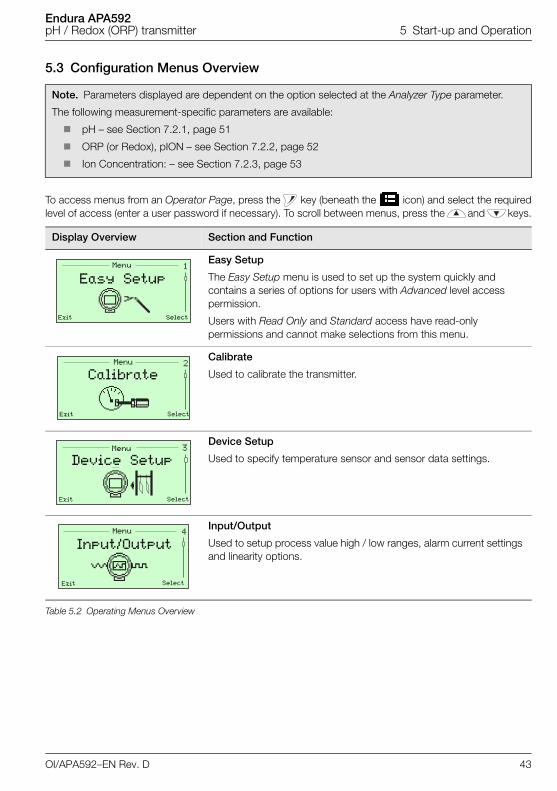
Display Overview Section and Function
Easy Setup
The Easy Setup menu is used to set up the system quickly and contains a series of options for users with Advanced level access permission.
Users with Read Only and Standard access have read-only permissions and cannot make selections from this menu.
Calibrate
Used to calibrate the transmitter.
Device Setup
Used to specify temperature sensor and sensor data settings.
Input/Output
Used to setup process value high / low ranges, alarm current settings and linearity options.
Table 5.2 Operating Menus Overview
�Menu
Exit Select
Easy Setup
�Menu
Exit Select
Calibrate
�Menu
Exit Select
Device Setup
�Menu
Exit Select
Input/Output
OI/APA592–EN Rev. D 43
Endura APA592pH / Redox (ORP) transmitter 5 Start-up and Operation
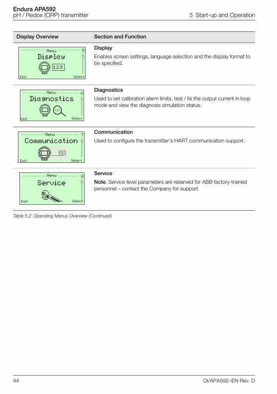
Display
Enables screen settings, language selection and the display format to be specified.
Diagnostics
Used to set calibration alarm limits, test / fix the output current in loop mode and view the diagnosis simulation status.
Communication
Used to configure the transmitter's HART communication support.
Service
Note. Service level parameters are reserved for ABB factory-trained personnel – contact the Company for support.
Display Overview Section and Function
Table 5.2 Operating Menus Overview (Continued)
�Menu
Exit Select
Display
�
���
Menu
Exit Select
Diagnostics
�Menu
Exit Select
Communication
Menu
Exit Select
Service
44 OI/APA592–EN Rev. D
Endura APA592pH / Redox (ORP) transmitter 6 Configuration
6 Configuration
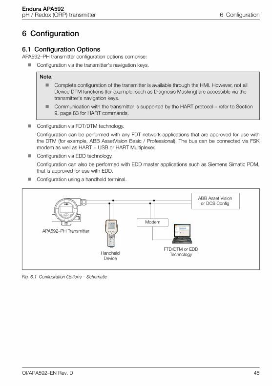
6.1 Configuration OptionsAPA592–PH transmitter configuration options comprise:
Configuration via the transmitter's navigation keys.
Configuration via FDT/DTM technology.
Configuration can be performed with any FDT network applications that are approved for use withthe DTM (for example, ABB AssetVision Basic / Professional). The bus can be connected via FSKmodem as well as HART + USB or HART Multiplexer.
Configuration via EDD technology.
Configuration can also be performed with EDD master applications such as Siemens Simatic PDM,that is approved for use with EDD.
Configuration using a handheld terminal.
Note.
Complete configuration of the transmitter is available through the HMI. However, not all Device DTM functions (for example, such as Diagnosis Masking) are accessible via the transmitter's navigation keys.
Communication with the transmitter is supported by the HART protocol – refer to Section 9, page 83 for HART commands.
Fig. 6.1 Configuration Options – Schematic
APA592–PH Transmitter
Handheld Device
FTD/DTM or EDD Technology
Modem
ABB Asset Visionor DCS Config
OI/APA592–EN Rev. D 45
Endura APA592pH / Redox (ORP) transmitter 6 Configuration
6.2 Configuration DIP Switch
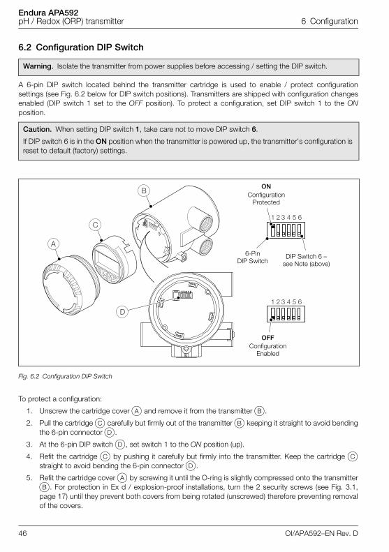
A 6-pin DIP switch located behind the transmitter cartridge is used to enable / protect configurationsettings (see Fig. 6.2 below for DIP switch positions). Transmitters are shipped with configuration changesenabled (DIP switch 1 set to the OFF position). To protect a configuration, set DIP switch 1 to the ONposition.
To protect a configuration:
1. Unscrew the cartridge cover A and remove it from the transmitter B.
2. Pull the cartridge C carefully but firmly out of the transmitter B keeping it straight to avoid bendingthe 6-pin connector D.
3. At the 6-pin DIP switch D, set switch 1 to the ON position (up).
4. Refit the cartridge C by pushing it carefully but firmly into the transmitter. Keep the cartridge Cstraight to avoid bending the 6-pin connector D.
5. Refit the cartridge cover A by screwing it until the O-ring is slightly compressed onto the transmitterB. For protection in Ex d / explosion-proof installations, turn the 2 security screws (see Fig. 3.1,page 17) until they prevent both covers from being rotated (unscrewed) therefore preventing removalof the covers.
Warning. Isolate the transmitter from power supplies before accessing / setting the DIP switch.
Caution. When setting DIP switch 1, take care not to move DIP switch 6.
If DIP switch 6 is in the ON position when the transmitter is powered up, the transmitter's configuration is reset to default (factory) settings.
Fig. 6.2 Configuration DIP Switch
ONConfiguration
Protected
OFFConfiguration
Enabled
6-Pin DIP Switch
DIP Switch 6 –see Note (above)
46 OI/APA592–EN Rev. D
Endura APA592pH / Redox (ORP) transmitter 7 Operator Pages and Menus
7 Operator Pages and Menus
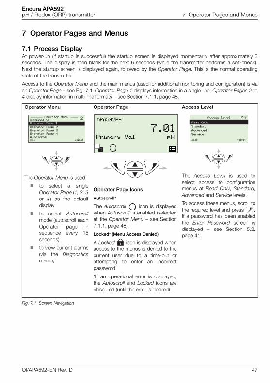
7.1 Process DisplayAt power-up (if startup is successful) the startup screen is displayed momentarily after approximately 3seconds. The display is then blank for the next 6 seconds (while the transmitter performs a self-check).Next the startup screen is displayed again, followed by the Operator Page. This is the normal operatingstate of the transmitter.
Access to the Operator Menu and the main menus (used for additional monitoring and configuration) is viaan Operator Page – see Fig. 7.1. Operator Page 1 displays information in a single line, Operator Pages 2 to4 display information in multi-line formats – see Section 7.1.1, page 48.
Operator Menu
The Operator Menu is used:
to select a singleOperator Page (1, 2, 3or 4) as the defaultdisplay
to select Autoscrollmode (autoscroll eachOperator page insequence every 15seconds)
to view current alarms(via the Diagnosticsmenu),
Operator Page Access Level
The Access Level is used toselect access to configurationmenus at Read Only, Standard,Advanced and Service levels.
To access these menus, scroll tothe required level and press .If a password has been enabledthe Enter Password screen isdisplayed – see Section 5.2,page 41.
Operator Page Icons
Autoscroll*
The Autoscroll icon is displayedwhen Autoscroll is enabled (selectedat the Operator Menu – see Section7.1.1, page 48).
Locked* (Menu Access Denied)
A Locked icon is displayed whenaccess to the menus is denied to thecurrent user due to a time-out orattempting to enter an incorrectpassword.
*If an operational error is displayed,the Autoscroll and Locked icons areobscured (until the error is cleared).
Fig. 7.1 Screen Navigation
�Operator MenuDiagnosticsOperator Page 1
Operator Page 2Operator Page 3Operator Page 4AutoscrollBack Select
1
APA592PH
7.01pHPrimary Val
Access Level
Read Only
Standard
Advanced
Service
Back Select
OI/APA592–EN Rev. D 47
Endura APA592pH / Redox (ORP) transmitter 7 Operator Pages and Menus
7.1.1 Operator Pages
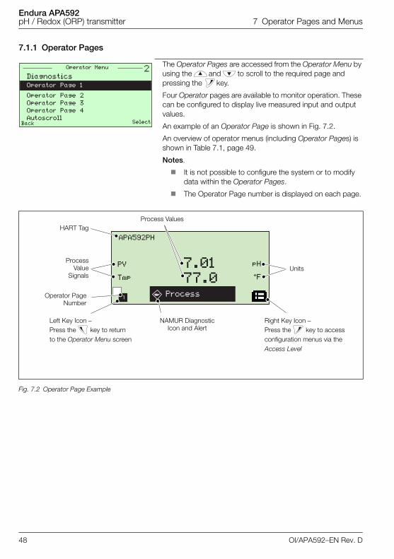
The Operator Pages are accessed from the Operator Menu by using the and to scroll to the required page and pressing the key.
Four Operator pages are available to monitor operation. These can be configured to display live measured input and output values.
An example of an Operator Page is shown in Fig. 7.2.
An overview of operator menus (including Operator Pages) is shown in Table 7.1, page 49.
Notes.
It is not possible to configure the system or to modify data within the Operator Pages.
The Operator Page number is displayed on each page.
Fig. 7.2 Operator Page Example
�Operator Menu
Back Select
Diagnostics
Operator Page 1
Operator Page 2
Operator Page 3
Operator Page 4
Autoscroll
1
APA592PH
Process
pH
°F
PV
Tmp
7.0177.0
Process ValuesHART Tag
ProcessValue
Signals
Left Key Icon – Press the key to return to the Operator Menu screen
Units
Right Key Icon – Press the key to access configuration menus via the Access Level
NAMUR Diagnostic Icon and Alert
Operator PageNumber
48 OI/APA592–EN Rev. D
Endura APA592pH / Redox (ORP) transmitter 7 Operator Pages and Menus
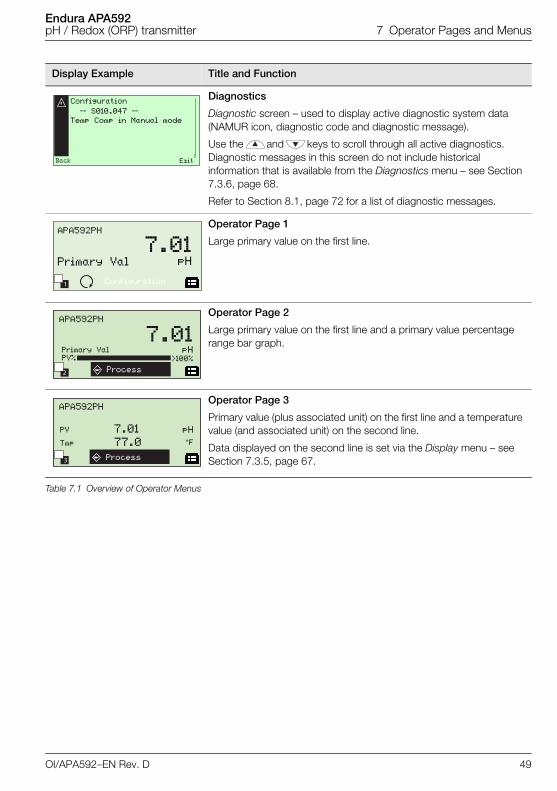
Display Example Title and Function
Diagnostics
Diagnostic screen – used to display active diagnostic system data (NAMUR icon, diagnostic code and diagnostic message).
Use the and keys to scroll through all active diagnostics. Diagnostic messages in this screen do not include historical information that is available from the Diagnostics menu – see Section 7.3.6, page 68.
Refer to Section 8.1, page 72 for a list of diagnostic messages.
Operator Page 1
Large primary value on the first line.
Operator Page 2
Large primary value on the first line and a primary value percentage range bar graph.
Operator Page 3
Primary value (plus associated unit) on the first line and a temperature value (and associated unit) on the second line.
Data displayed on the second line is set via the Display menu – see Section 7.3.5, page 67.
Table 7.1 Overview of Operator Menus
Configuration
–– S010.047 ––
Temp Comp in Manual mode
Back Exit
1
APA592PH
7.01pHPrimary Val
Configuration
2
APA592PH
Process
7.01pH
>100%
Primary ValPV%
3
APA592PH
Process
pH
°F
PV
Tmp
7.01
77.0
OI/APA592–EN Rev. D 49
Endura APA592pH / Redox (ORP) transmitter 7 Operator Pages and Menus
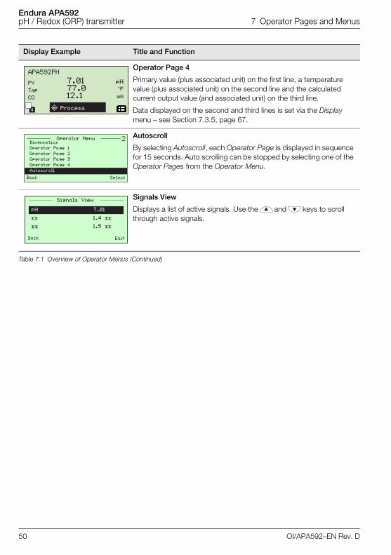
Operator Page 4
Primary value (plus associated unit) on the first line, a temperature value (plus associated unit) on the second line and the calculated current output value (and associated unit) on the third line.
Data displayed on the second and third lines is set via the Display menu – see Section 7.3.5, page 67.
Autoscroll
By selecting Autoscroll, each Operator Page is displayed in sequence for 15 seconds. Auto scrolling can be stopped by selecting one of the Operator Pages from the Operator Menu.
Signals View
Displays a list of active signals. Use the and keys to scroll through active signals.
Display Example Title and Function
Table 7.1 Overview of Operator Menus (Continued)
4
APA592PH
Process
pH°F
mA
PV
Tmp
CO
7.0177.012.1
�Diagnostics
Operator Page 1
Operator Page 2
Operator Page 3
Operator Page 4
Autoscroll Back Select
Operator Menu
Signals View
pH
xx
xx
Back Exit
7.01
1.4 xx
1.5 xx
50 OI/APA592–EN Rev. D
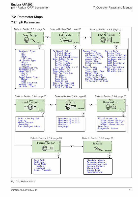
Endura APA592pH / Redox (ORP) transmitter 7 Operator Pages and Menus
7.2 Parameter Maps
7.2.1 pH Parameters
Fig. 7.3 pH Parameters
Analyzer TypepHORPpIONIon Conc
pH Sensor TypeGlassAntimonyCustom
Isopotential Pt.Asymmetric Pt.Temp. Unit
Deg C Deg F
Temp. Comp. TypeManualAutoAuto Solution
Manual TemppH Soln. Coeff.
Easy SetupMenu Menu Menu
Menu Menu Menu
Menu Menu
Select Select Select
Select Select Select
Select Select
Calibrate Device Setup
Input/Output Display Diagnostics
Communication Service
PV Manual Cal1 Point Manual2 Point ManualOutput Hold/Release
Auto Buffer SetupBuffer TypeBuffer 1 ValueBuffer 2ValueUser def Soln.1 / 2
Auto Buffer CalTemperature CalEdit PV, Temp CalPV SlopePV OffsetTemp SlopeTemp Offset
Reset PV, Temp CalAnalog Output TrimTrim 4 / 20 mA
Sensor TypeAnalyzer TypepH Sensor Type Isopotential Pt.Asymmetric Pt Sensor DiagReference Imp. Limit
Temp. Sensor Temp. unitTemp. Comp. TypeManual TemppH Soln. Coeff.Temp. Sensor TypeRun TC RecognitionTC Recognition Stat
Device Info Device Type Device Serial No. Software Version Hardware Version HART TagHART DescriptorLong Tag
Write ProtectionHW write prot.SW write prot.
PV Hi / Lo Rng ValDamping Alarm CurrentLinearityFunction-gen table
Operator pg 3 ln 2Operator pg 4 ln 2Operator pg 4 ln 3Contrast Language
PV cal alarm limSlope alarm lim highSlope alarm lim loOffset alarm Lim +/–
Loop TestDiagnosis Status
Poll AddrHART TagBurst ModeStatusCommand
Resp. Preamble
Standard accessAdvanced accessFunction key lockFactory DefaultGlass DiagGround LoopManufacturing
Refer to Section 7.3.1, page 54 Refer to Section 7.3.2, page 56 Refer to Section 7.3.3, page 63
Refer to Section 7.3.4, page 66 Refer to Section 7.3.5, page 67 Refer to Section 7.3.6, page 68
Refer to Section 7.3.7, page 69 Refer to Section 7.3.8, page 70
OI/APA592–EN Rev. D 51
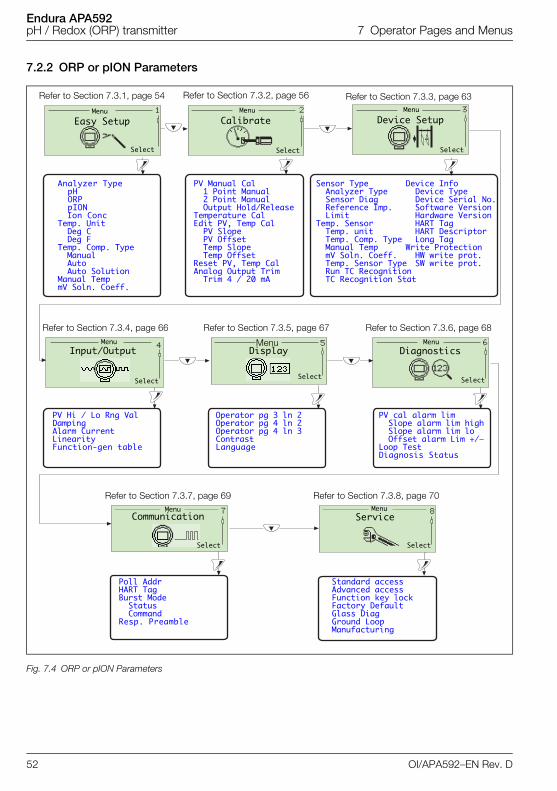
Endura APA592pH / Redox (ORP) transmitter 7 Operator Pages and Menus
7.2.2 ORP or pION Parameters
Fig. 7.4 ORP or pION Parameters
Analyzer TypepHORPpIONIon Conc
Temp. UnitDeg CDeg F
Temp. Comp. TypeManualAutoAuto Solution
Manual TempmV Soln. Coeff.
Easy SetupMenu Menu Menu
Menu Menu Menu
Menu Menu
Select Select Select
Select Select Select
Select Select
Calibrate Device Setup
Input/Output Display Diagnostics
Communication Service
PV Manual Cal1 Point Manual2 Point ManualOutput Hold/Release
Temperature CalEdit PV, Temp CalPV SlopePV OffsetTemp SlopeTemp Offset
Reset PV, Temp CalAnalog Output TrimTrim 4 / 20 mA
Sensor TypeAnalyzer TypeSensor DiagReference Imp. Limit
Temp. Sensor Temp. unitTemp. Comp. TypeManual TempmV Soln. Coeff.Temp. Sensor TypeRun TC RecognitionTC Recognition Stat
Device Info Device Type Device Serial No. Software Version Hardware Version HART TagHART DescriptorLong Tag
Write ProtectionHW write prot.SW write prot.
PV Hi / Lo Rng ValDamping Alarm CurrentLinearity Function-gen table
Operator pg 3 ln 2Operator pg 4 ln 2Operator pg 4 ln 3Contrast Language
PV cal alarm limSlope alarm lim highSlope alarm lim loOffset alarm Lim +/–
Loop TestDiagnosis Status
Poll AddrHART TagBurst ModeStatusCommand
Resp. Preamble
Standard accessAdvanced accessFunction key lockFactory DefaultGlass DiagGround LoopManufacturing
Refer to Section 7.3.1, page 54 Refer to Section 7.3.2, page 56 Refer to Section 7.3.3, page 63
Refer to Section 7.3.4, page 66 Refer to Section 7.3.5, page 67 Refer to Section 7.3.6, page 68
Refer to Section 7.3.7, page 69 Refer to Section 7.3.8, page 70
52 OI/APA592–EN Rev. D
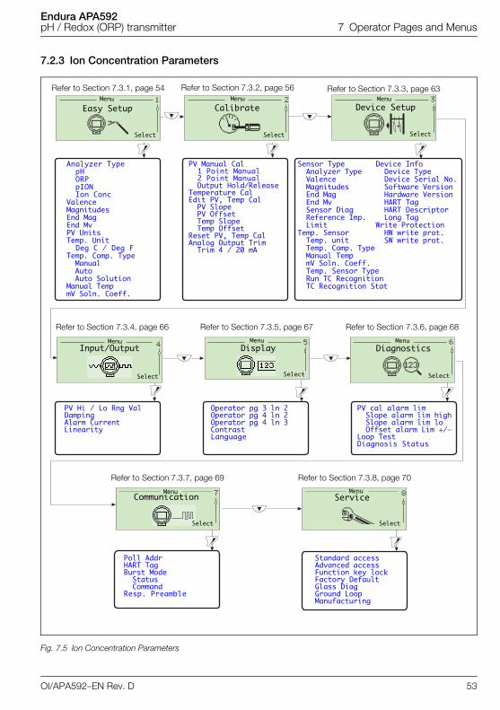
Endura APA592pH / Redox (ORP) transmitter 7 Operator Pages and Menus
7.2.3 Ion Concentration Parameters
Fig. 7.5 Ion Concentration Parameters
Analyzer TypepHORPpIONIon Conc
ValenceMagnitudes End MagEnd MvPV UnitsTemp. Unit
Deg C / Deg FTemp. Comp. Type
ManualAutoAuto Solution
Manual TempmV Soln. Coeff.
Easy SetupMenu Menu Menu
Menu Menu Menu
Menu Menu
Select Select Select
Select Select Select
Select Select
Calibrate Device Setup
Input/Output Display Diagnostics
Communication Service
PV Manual Cal1 Point Manual2 Point ManualOutput Hold/Release
Temperature CalEdit PV, Temp CalPV SlopePV OffsetTemp SlopeTemp Offset
Reset PV, Temp CalAnalog Output TrimTrim 4 / 20 mA
Sensor TypeAnalyzer TypeValence MagnitudesEnd MagEnd MvSensor DiagReference Imp. Limit
Temp. Sensor Temp. unitTemp. Comp. TypeManual TempmV Soln. Coeff.Temp. Sensor TypeRun TC RecognitionTC Recognition Stat
Device Info Device Type Device Serial No. Software Version Hardware Version HART TagHART DescriptorLong Tag
Write ProtectionHW write prot.SW write prot.
PV Hi / Lo Rng ValDamping Alarm CurrentLinearity
Operator pg 3 ln 2Operator pg 4 ln 2Operator pg 4 ln 3Contrast Language
PV cal alarm limSlope alarm lim highSlope alarm lim loOffset alarm Lim +/–
Loop TestDiagnosis Status
Poll AddrHART TagBurst ModeStatusCommand
Resp. Preamble
Standard accessAdvanced accessFunction key lockFactory DefaultGlass DiagGround LoopManufacturing
Refer to Section 7.3.1, page 54 Refer to Section 7.3.2, page 56 Refer to Section 7.3.3, page 63
Refer to Section 7.3.4, page 66 Refer to Section 7.3.5, page 67 Refer to Section 7.3.6, page 68
Refer to Section 7.3.7, page 69 Refer to Section 7.3.8, page 70
OI/APA592–EN Rev. D 53
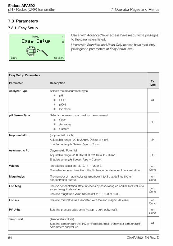
Endura APA592pH / Redox (ORP) transmitter 7 Operator Pages and Menus
7.3 Parameters
7.3.1 Easy Setup
Users with Advanced level access have read / write privileges to the parameters listed.
Users with Standard and Read Only access have read-only privileges to parameters at Easy Setup level.
Easy Setup Parameters
Parameter Description Tx Type
Analyzer Type Selects the measurement type:
pH
ORP
pION
Ion Conc
All
pH Sensor Type Selects the sensor type used for measurement:
Glass
Antimony
Custom
pH
Isopotential Pt. (Isopotential Point)
Adjustable range –20 to 20 pH. Default = 7 pH.
Enabled when pH Sensor Type = Custom.
pH
Asymmetric Pt. (Asymmetric Potential)
Adjustable range –2000 to 2000 mV. Default = 0 mV
Enabled when pH Sensor Type = Custom.
PH
Valence Ion valence selection: -3, -2, -1, 1, 2, or 3.
The valence determines the millivolt change per decade of concentration.Ion
Conc
Magnitudes The number of magnitudes ranging from 1 to 3 that defines the ion concentration output.
Ion Conc
End Mag The ion concentration state functions by associating an end millivolt value to an end magnitude value.
The end magnitude value can be set to 10, 100 or 1000.
Ion Conc
End mV The end millivolt value associated with the end magnitude value. Ion Conc
PV Units Sets the process value units (%, ppm, µg/l, ppb, mg/l). Ion Conc
Temp. unit (Temperature Units)
Sets the temperature unit (°C or °F) applied to all transmitter temperature parameters and values.
All
�Menu
Exit Select
Easy Setup
54 OI/APA592–EN Rev. D
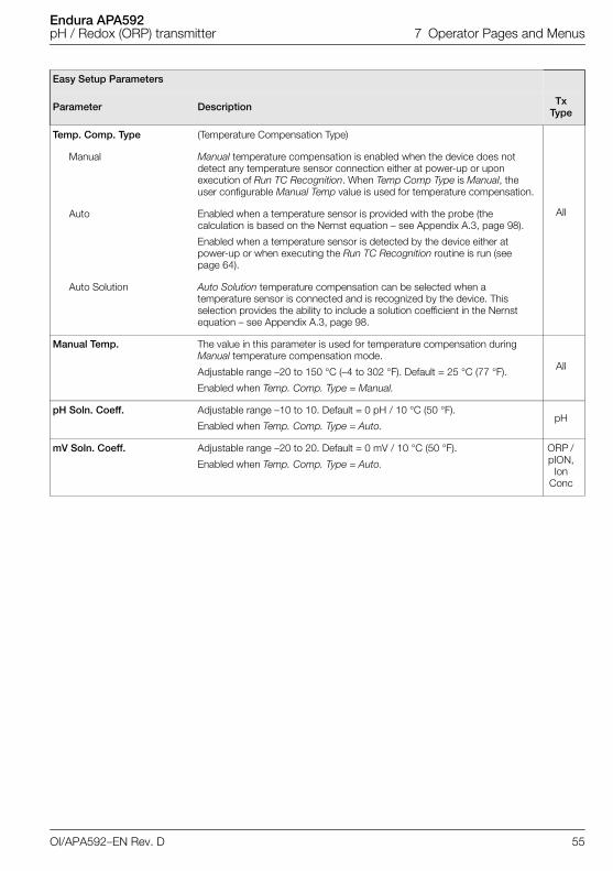
Endura APA592pH / Redox (ORP) transmitter 7 Operator Pages and Menus
Temp. Comp. Type (Temperature Compensation Type)
All
Manual Manual temperature compensation is enabled when the device does not detect any temperature sensor connection either at power-up or upon execution of Run TC Recognition. When Temp Comp Type is Manual, the user configurable Manual Temp value is used for temperature compensation.
Auto Enabled when a temperature sensor is provided with the probe (the calculation is based on the Nernst equation – see Appendix A.3, page 98).
Enabled when a temperature sensor is detected by the device either at power-up or when executing the Run TC Recognition routine is run (see page 64).
Auto Solution Auto Solution temperature compensation can be selected when a temperature sensor is connected and is recognized by the device. This selection provides the ability to include a solution coefficient in the Nernst equation – see Appendix A.3, page 98.
Manual Temp. The value in this parameter is used for temperature compensation during Manual temperature compensation mode.
Adjustable range –20 to 150 °C (–4 to 302 °F). Default = 25 °C (77 °F).
Enabled when Temp. Comp. Type = Manual.
All
pH Soln. Coeff. Adjustable range –10 to 10. Default = 0 pH / 10 °C (50 °F).
Enabled when Temp. Comp. Type = Auto. pH
mV Soln. Coeff. Adjustable range –20 to 20. Default = 0 mV / 10 °C (50 °F).
Enabled when Temp. Comp. Type = Auto.
ORP / pION,
Ion Conc
Easy Setup Parameters
Parameter Description Tx Type
OI/APA592–EN Rev. D 55
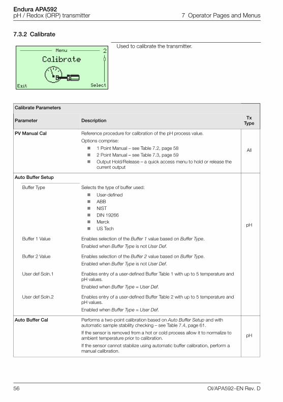
Endura APA592pH / Redox (ORP) transmitter 7 Operator Pages and Menus
7.3.2 Calibrate
Used to calibrate the transmitter.
Calibrate Parameters
Parameter Description Tx Type
PV Manual Cal Reference procedure for calibration of the pH process value.
Options comprise:
1 Point Manual – see Table 7.2, page 58 2 Point Manual – see Table 7.3, page 59 Output Hold/Release – a quick access menu to hold or release the
current output
All
Auto Buffer Setup
pH
Buffer Type Selects the type of buffer used:
User-defined ABB NIST DIN 19266 Merck US Tech
Buffer 1 Value Enables selection of the Buffer 1 value based on Buffer Type.
Enabled when Buffer Type is not User Def.
Buffer 2 Value Enables selection of the Buffer 2 value based on Buffer Type.
Enabled when Buffer Type is not User Def.
User def Soln.1 Enables entry of a user-defined Buffer Table 1 with up to 5 temperature and pH values.
Enabled when Buffer Type = User Def.
User def Soln.2 Enables entry of a user-defined Buffer Table 2 with up to 5 temperature and pH values.
Enabled when Buffer Type = User Def.
Auto Buffer Cal Performs a two-point calibration based on Auto Buffer Setup and with automatic sample stability checking – see Table 7.4, page 61.
If the sensor is removed from a hot or cold process allow it to normalize to ambient temperature prior to calibration.
If the sensor cannot stabilize using automatic buffer calibration, perform a manual calibration.
pH
�Menu
Exit Select
Calibrate
56 OI/APA592–EN Rev. D
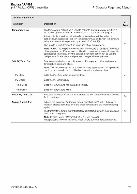
Endura APA592pH / Redox (ORP) transmitter 7 Operator Pages and Menus
Temperature Cal The temperature calibration is used to calibrate the temperature input from the sensor against a standard known reading – see Table 7.5, page 62.
A two-point temperature calibration is performed using this routine by calibrating, in succession, at a low temperature value and a high temperature value (the two values separated by at least 20 °C [68 °F]).
This results in both temperature slope and offset computation.
Note – ORP. The temperature effect on ORP sensors is negligible. The effect of temperature on pION sensors is difficult to characterize, except for specific applications. Therefore, only the solution coefficient option can be used to compensate for electrode and process changes with temperature.
All
Edit PV, Temp Cal Enables manual adjustment of the sensor PV slope and offset and sensor temperature slope and offset.
Note. This function may not be suitable for many applications, but it provides quick, easy access to these calibration values for troubleshooting.
AllPV Slope Edits the PV Slope value as a percentage.
PV Offset Edits the PV Offset value.
Temp Slope Edits the Temp Slope value as a percentage.
Temp Offset Edits the Temp Slope value.
Reset PV, Temp Cal Resets all process sensor and temperature sensor calibration data to default factory settings. All
Analog Output Trim Adjusts the maximum / minimum output signals (4 to 20 mA, ±0.5 mA) to maintain precise transmission of the process variable to the final monitoring system.
The transmitter's output current is factory calibrated, however, the output can be trimmed if required.
Note. Enabled when HART Poll Addr = 0 – see page 69. Not applicable to HART multidrop mode where current output is not used.
All
Calibrate Parameters
Parameter Description Tx Type
OI/APA592–EN Rev. D 57
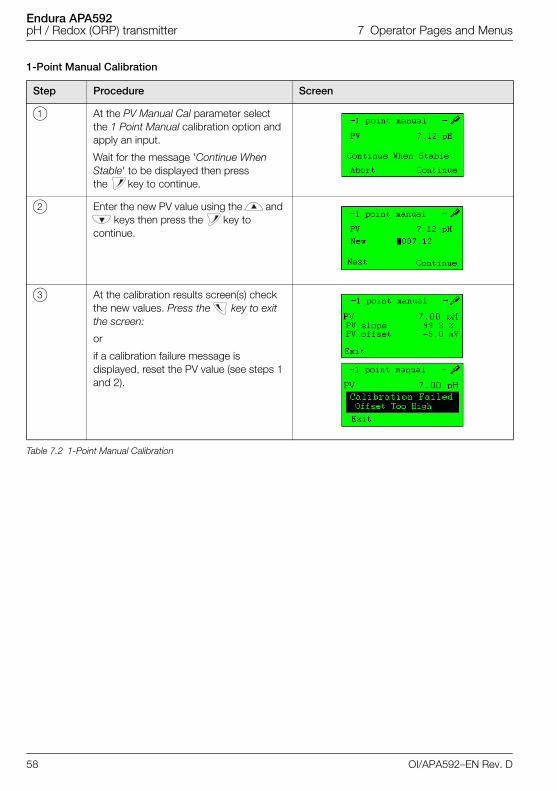
Endura APA592pH / Redox (ORP) transmitter 7 Operator Pages and Menus
1-Point Manual Calibration
Step Procedure Screen
1 At the PV Manual Cal parameter select the 1 Point Manual calibration option and apply an input.
Wait for the message 'Continue When Stable' to be displayed then press the key to continue.
2 Enter the new PV value using the and keys then press the key to
continue.
3 At the calibration results screen(s) check the new values. Press the key to exit the screen:
or
if a calibration failure message is displayed, reset the PV value (see steps 1 and 2).
Table 7.2 1-Point Manual Calibration
58 OI/APA592–EN Rev. D
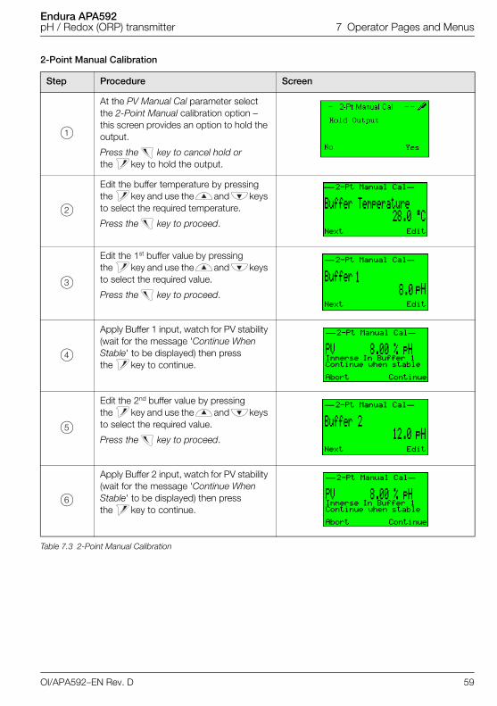
Endura APA592pH / Redox (ORP) transmitter 7 Operator Pages and Menus
2-Point Manual Calibration
Step Procedure Screen
1
At the PV Manual Cal parameter select the 2-Point Manual calibration option – this screen provides an option to hold the output.
Press the key to cancel hold or the key to hold the output.
2
Edit the buffer temperature by pressing the key and use the and keys to select the required temperature.
Press the key to proceed.
3
Edit the 1st buffer value by pressing the key and use the and keys to select the required value.
Press the key to proceed.
4
Apply Buffer 1 input, watch for PV stability (wait for the message 'Continue When Stable' to be displayed) then press the key to continue.
5
Edit the 2nd buffer value by pressing the key and use the and keys to select the required value.
Press the key to proceed.
6
Apply Buffer 2 input, watch for PV stability (wait for the message 'Continue When Stable' to be displayed) then press the key to continue.
Table 7.3 2-Point Manual Calibration
OI/APA592–EN Rev. D 59
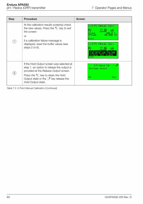
Endura APA592pH / Redox (ORP) transmitter 7 Operator Pages and Menus
7
At the calibration results screen(s) check the new values. Press the key to exit the screen:
or
if a calibration failure message is displayed, reset the buffer values (see steps 2 to 6).
8
If the Hold Output screen was selected at step 1, an option to release the output is provided at the Release Output screen.
Press the key to retain the Hold Output state or the key release the Hold Output state.
Step Procedure Screen
Table 7.3 2-Point Manual Calibration (Continued)
60 OI/APA592–EN Rev. D
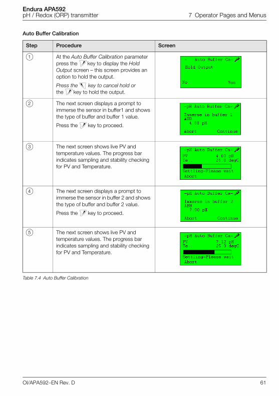
Endura APA592pH / Redox (ORP) transmitter 7 Operator Pages and Menus
Auto Buffer Calibration
Step Procedure Screen
1 At the Auto Buffer Calibration parameter press the key to display the Hold Output screen – this screen provides an option to hold the output.
Press the key to cancel hold or the key to hold the output.
2 The next screen displays a prompt to immerse the sensor in buffer1 and shows the type of buffer and buffer 1 value.
Press the key to proceed.
3 The next screen shows live PV and temperature values. The progress bar indicates sampling and stability checking for PV and Temperature.
4 The next screen displays a prompt to immerse the sensor in buffer 2 and shows the type of buffer and buffer 2 value.
Press the key to proceed.
5 The next screen shows live PV and temperature values. The progress bar indicates sampling and stability checking for PV and Temperature.
Table 7.4 Auto Buffer Calibration
OI/APA592–EN Rev. D 61
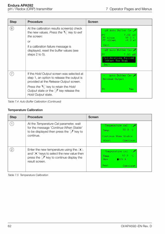
Endura APA592pH / Redox (ORP) transmitter 7 Operator Pages and Menus
Temperature Calibration
6 At the calibration results screen(s) check the new values. Press the key to exit the screen:
or
if a calibration failure message is displayed, reset the buffer values (see steps 2 to 5).
7 If the Hold Output screen was selected at step 1, an option to release the output is provided at the Release Output screen.
Press the key to retain the Hold Output state or the key release the Hold Output state.
Step Procedure Screen
1 At the Temperature Cal parameter, wait for the message 'Continue When Stable' to be displayed then press the key to continue.
2 Enter the new temperature using the and keys to select the new value then press the key to continue display the result screen.
Table 7.5 Temperature Calibration
Step Procedure Screen
Table 7.4 Auto Buffer Calibration (Continued)
62 OI/APA592–EN Rev. D
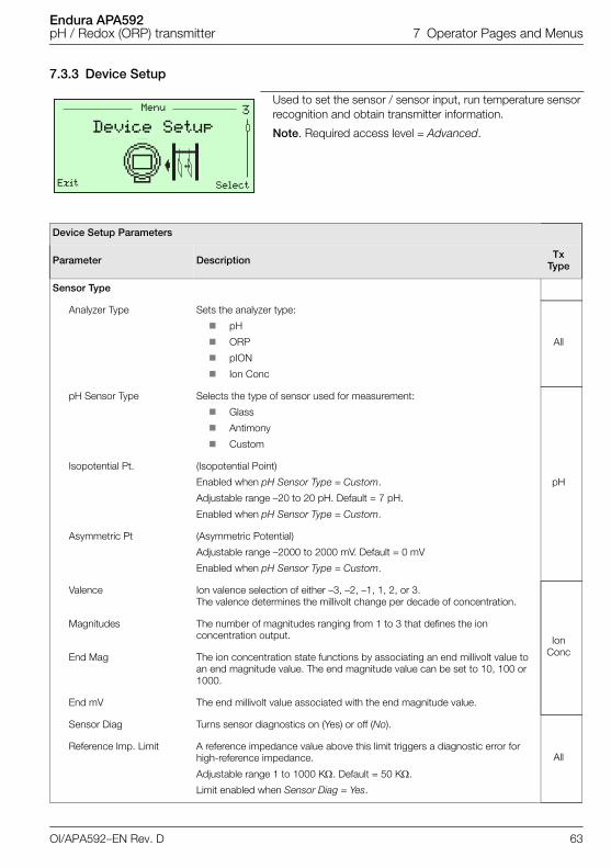
Endura APA592pH / Redox (ORP) transmitter 7 Operator Pages and Menus
7.3.3 Device Setup
Used to set the sensor / sensor input, run temperature sensor recognition and obtain transmitter information.
Note. Required access level = Advanced.
Device Setup Parameters
Parameter Description Tx Type
Sensor Type
Analyzer Type Sets the analyzer type:
pH
ORP
pION
Ion Conc
All
pH Sensor Type Selects the type of sensor used for measurement:
Glass
Antimony
Custom
pH
Isopotential Pt. (Isopotential Point)
Enabled when pH Sensor Type = Custom.
Adjustable range –20 to 20 pH. Default = 7 pH.
Enabled when pH Sensor Type = Custom.
Asymmetric Pt (Asymmetric Potential)
Adjustable range –2000 to 2000 mV. Default = 0 mV
Enabled when pH Sensor Type = Custom.
Valence Ion valence selection of either –3, –2, –1, 1, 2, or 3. The valence determines the millivolt change per decade of concentration.
Ion Conc
Magnitudes The number of magnitudes ranging from 1 to 3 that defines the ion concentration output.
End Mag The ion concentration state functions by associating an end millivolt value to an end magnitude value. The end magnitude value can be set to 10, 100 or 1000.
End mV The end millivolt value associated with the end magnitude value.
Sensor Diag Turns sensor diagnostics on (Yes) or off (No).
AllReference Imp. Limit A reference impedance value above this limit triggers a diagnostic error for
high-reference impedance.
Adjustable range 1 to 1000 K. Default = 50 K.
Limit enabled when Sensor Diag = Yes.
�Menu
Exit Select
Device Setup
OI/APA592–EN Rev. D 63
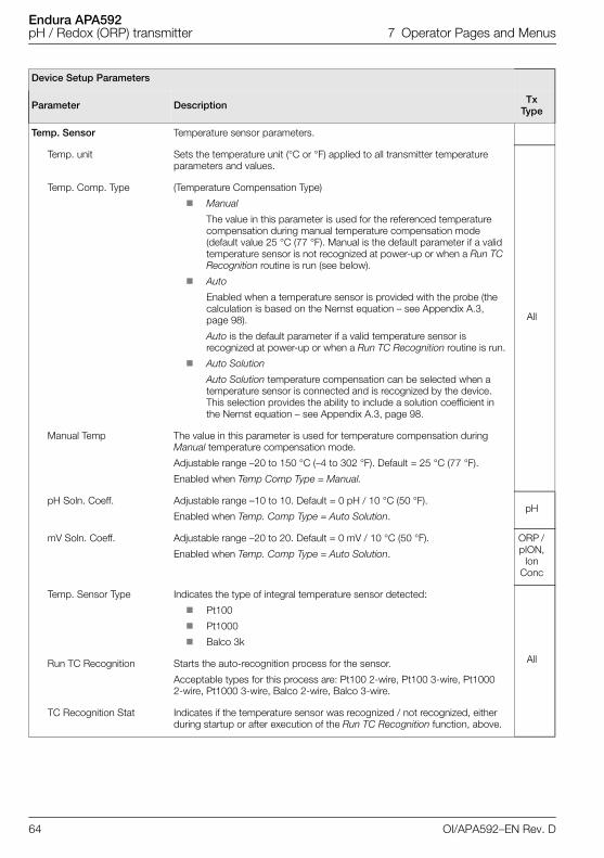
Endura APA592pH / Redox (ORP) transmitter 7 Operator Pages and Menus
Temp. Sensor Temperature sensor parameters.
Temp. unit Sets the temperature unit (°C or °F) applied to all transmitter temperature parameters and values.
All
Temp. Comp. Type (Temperature Compensation Type)
Manual
The value in this parameter is used for the referenced temperature compensation during manual temperature compensation mode (default value 25 °C (77 °F). Manual is the default parameter if a valid temperature sensor is not recognized at power-up or when a Run TC Recognition routine is run (see below).
Auto
Enabled when a temperature sensor is provided with the probe (the calculation is based on the Nernst equation – see Appendix A.3, page 98).
Auto is the default parameter if a valid temperature sensor is recognized at power-up or when a Run TC Recognition routine is run.
Auto Solution
Auto Solution temperature compensation can be selected when a temperature sensor is connected and is recognized by the device. This selection provides the ability to include a solution coefficient in the Nernst equation – see Appendix A.3, page 98.
Manual Temp The value in this parameter is used for temperature compensation during Manual temperature compensation mode.
Adjustable range –20 to 150 °C (–4 to 302 °F). Default = 25 °C (77 °F).
Enabled when Temp Comp Type = Manual.
pH Soln. Coeff. Adjustable range –10 to 10. Default = 0 pH / 10 °C (50 °F).
Enabled when Temp. Comp Type = Auto Solution.pH
mV Soln. Coeff. Adjustable range –20 to 20. Default = 0 mV / 10 °C (50 °F).
Enabled when Temp. Comp Type = Auto Solution.
ORP / pION,
Ion Conc
Temp. Sensor Type Indicates the type of integral temperature sensor detected:
Pt100
Pt1000
Balco 3k
AllRun TC Recognition Starts the auto-recognition process for the sensor.
Acceptable types for this process are: Pt100 2-wire, Pt100 3-wire, Pt1000 2-wire, Pt1000 3-wire, Balco 2-wire, Balco 3-wire.
TC Recognition Stat Indicates if the temperature sensor was recognized / not recognized, either during startup or after execution of the Run TC Recognition function, above.
Device Setup Parameters
Parameter Description Tx Type
64 OI/APA592–EN Rev. D
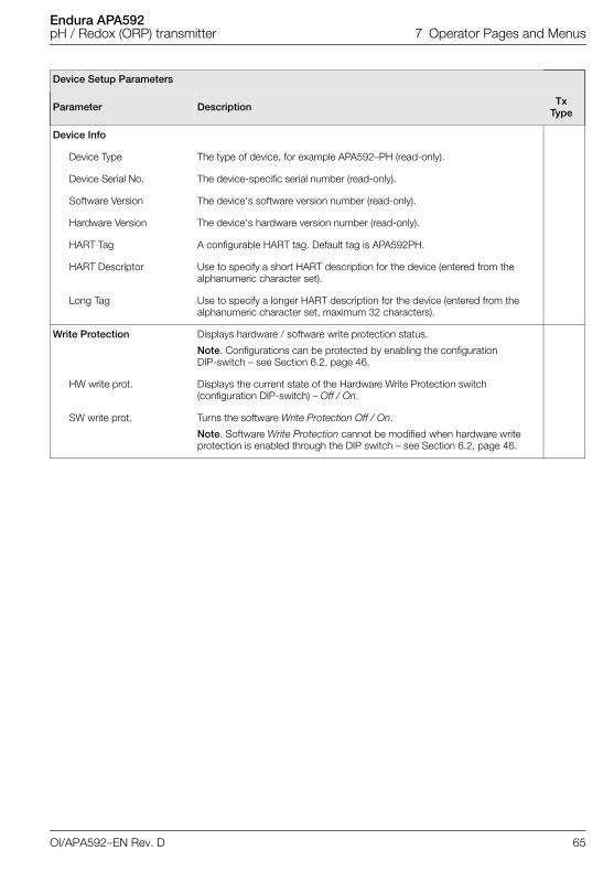
Endura APA592pH / Redox (ORP) transmitter 7 Operator Pages and Menus
Device Info
Device Type The type of device, for example APA592–PH (read-only).
Device Serial No. The device-specific serial number (read-only).
Software Version The device's software version number (read-only).
Hardware Version The device's hardware version number (read-only).
HART Tag A configurable HART tag. Default tag is APA592PH.
HART Descriptor Use to specify a short HART description for the device (entered from the alphanumeric character set).
Long Tag Use to specify a longer HART description for the device (entered from the alphanumeric character set, maximum 32 characters).
Write Protection Displays hardware / software write protection status.
Note. Configurations can be protected by enabling the configuration DIP-switch – see Section 6.2, page 46.
HW write prot. Displays the current state of the Hardware Write Protection switch (configuration DIP-switch) – Off / On.
SW write prot. Turns the software Write Protection Off / On.
Note. Software Write Protection cannot be modified when hardware write protection is enabled through the DIP switch – see Section 6.2, page 46.
Device Setup Parameters
Parameter Description Tx Type
OI/APA592–EN Rev. D 65
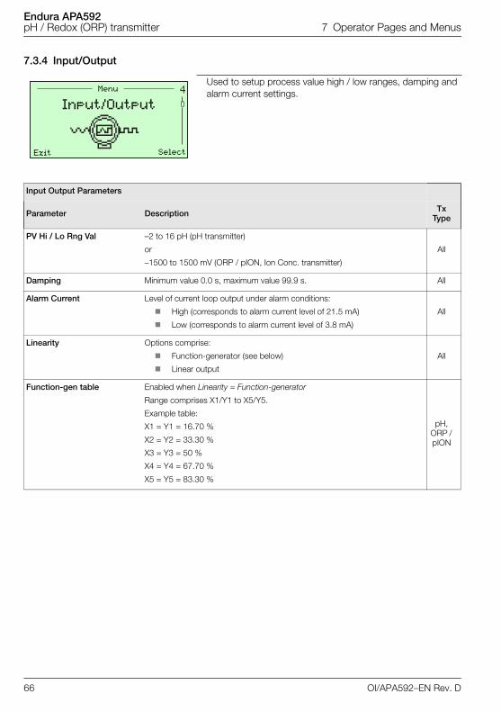
Endura APA592pH / Redox (ORP) transmitter 7 Operator Pages and Menus
7.3.4 Input/Output
Used to setup process value high / low ranges, damping and alarm current settings.
Input Output Parameters
Parameter Description Tx Type
PV Hi / Lo Rng Val –2 to 16 pH (pH transmitter)
or
–1500 to 1500 mV (ORP / pION, Ion Conc. transmitter)
All
Damping Minimum value 0.0 s, maximum value 99.9 s. All
Alarm Current Level of current loop output under alarm conditions:
High (corresponds to alarm current level of 21.5 mA)
Low (corresponds to alarm current level of 3.8 mA)
All
Linearity Options comprise:
Function-generator (see below)
Linear output
All
Function-gen table Enabled when Linearity = Function-generator
Range comprises X1/Y1 to X5/Y5.
Example table:
X1 = Y1 = 16.70 %
X2 = Y2 = 33.30 %
X3 = Y3 = 50 %
X4 = Y4 = 67.70 %
X5 = Y5 = 83.30 %
pH, ORP / pION
�Menu
Exit Select
Input/Output
66 OI/APA592–EN Rev. D
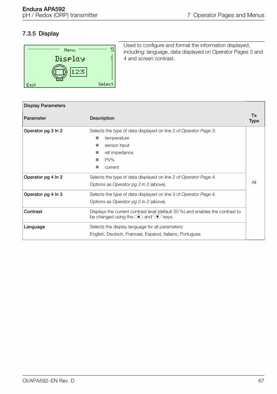
Endura APA592pH / Redox (ORP) transmitter 7 Operator Pages and Menus
7.3.5 Display
Used to configure and format the information displayed, including: language, data displayed on Operator Pages 3 and 4 and screen contrast.
Display Parameters
Parameter Description Tx Type
Operator pg 3 ln 2 Selects the type of data displayed on line 2 of Operator Page 3:
temperature
sensor input
ref impedance
PV%
current
AllOperator pg 4 ln 2 Selects the type of data displayed on line 2 of Operator Page 4.
Options as Operator pg 3 ln 2 (above).
Operator pg 4 ln 3 Selects the type of data displayed on line 3 of Operator Page 4.
Options as Operator pg 3 ln 2 (above).
Contrast Displays the current contrast level (default 50 %) and enables the contrast to be changed using the and keys.
Language Selects the display language for all parameters:
English, Deutsch, Francais, Espanol, Italiano, Portugues
�Menu
Exit Select
Display
OI/APA592–EN Rev. D 67
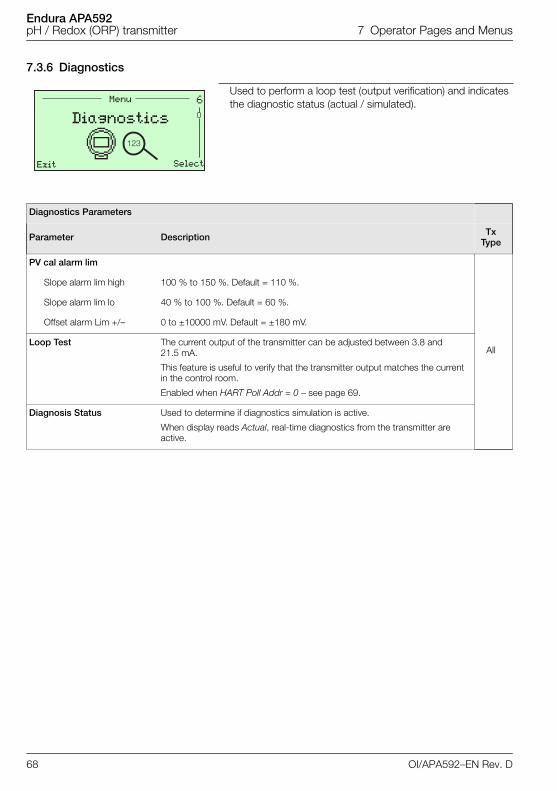
Endura APA592pH / Redox (ORP) transmitter 7 Operator Pages and Menus
7.3.6 Diagnostics
Used to perform a loop test (output verification) and indicates the diagnostic status (actual / simulated).
Diagnostics Parameters
Parameter Description Tx Type
PV cal alarm lim
All
Slope alarm lim high 100 % to 150 %. Default = 110 %.
Slope alarm lim lo 40 % to 100 %. Default = 60 %.
Offset alarm Lim +/– 0 to ±10000 mV. Default = ±180 mV.
Loop Test The current output of the transmitter can be adjusted between 3.8 and 21.5 mA.
This feature is useful to verify that the transmitter output matches the current in the control room.
Enabled when HART Poll Addr = 0 – see page 69.
Diagnosis Status Used to determine if diagnostics simulation is active.
When display reads Actual, real-time diagnostics from the transmitter are active.
�
���
Menu
Exit Select
Diagnostics
68 OI/APA592–EN Rev. D
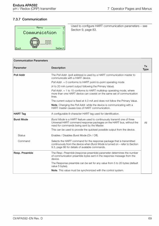
Endura APA592pH / Redox (ORP) transmitter 7 Operator Pages and Menus
7.3.7 Communication
Used to configure HART communication parameters – see Section 9, page 83.
Communication Parameters
Parameter Description Tx Type
Poll Addr The Poll Addr. (poll address) is used by a HART communication master to communicate with a HART device.
Poll Addr. = 0 conforms to HART point-to-point operating mode
(4 to 20 mA current output following the Primary Value).
Poll Addr. = 1 to 15 conforms to HART multidrop operating mode, where more than one HART device can coexist on the same set of communication lines.
The current output is fixed at 4.0 mA and does not follow the Primary Value.
Note. Changing the Poll Addr. while the device is communicating with a HART master causes loss of HART communication.
All
HART Tag A configurable 8-character HART tag used for identification.
Burst Mode Burst Mode is a HART feature used to continuously transmit one of three Universal HART command response packages on the HART bus, without the need for commands being sent by the Master.
This can be used to provide the quickest possible output from the device.
Status Enables / Disables Burst Mode (On / Off).
Command Selects the HART command for the response package that is transmitted continuously from the device when Burst Mode is turned on – refer to Section 9.3, page 86 for details of available commands.
Resp. Preamble The Resp. Preamble (response preamble) parameter determines the number of communication preamble bytes sent in the response message from the device.
The Response preamble can be set for any value from 5 to 20 bytes (default value 5 bytes).
Note. This value must be synchronized with the control system.
�Menu
Exit Select
Communication
OI/APA592–EN Rev. D 69
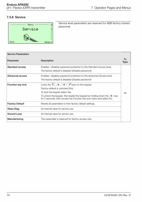
Endura APA592pH / Redox (ORP) transmitter 7 Operator Pages and Menus
7.3.8 Service
Service level parameters are reserved for ABB factory-trained personnel.
Service Parameters
Parameter Description Tx Type
Standard access Enables / disables password protection to the Standard Access level.
The factory default is disabled (Disable password).
All
Advanced access Enables / disables password protection to the Advanced Access level.
The factory default is disabled (Disable password)
Function key lock Locks the , , keys on the keypad.
Factory default is unlocked (No).
To lock the keypad select Yes.
To unlock the keypad, first enable the keypad by holding down the key for 5 seconds, then access the Function key lock menu and select No.
Factory Default Resets all parameters to their factory default settings.
Glass Diag An internal value for service use.
Ground Loop An internal value for service use.
Manufacturing This parameter is reserved for factory access only.
Menu
Exit Select
Service
70 OI/APA592–EN Rev. D
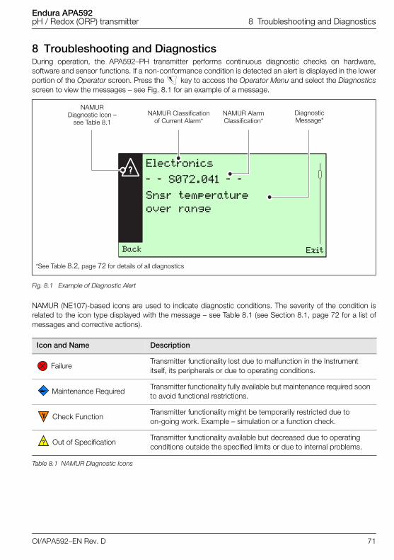
Endura APA592pH / Redox (ORP) transmitter 8 Troubleshooting and Diagnostics
8 Troubleshooting and DiagnosticsDuring operation, the APA592–PH transmitter performs continuous diagnostic checks on hardware,software and sensor functions. If a non-conformance condition is detected an alert is displayed in the lowerportion of the Operator screen. Press the key to access the Operator Menu and select the Diagnosticsscreen to view the messages – see Fig. 8.1 for an example of a message.
NAMUR (NE107)-based icons are used to indicate diagnostic conditions. The severity of the condition isrelated to the icon type displayed with the message – see Table 8.1 (see Section 8.1, page 72 for a list ofmessages and corrective actions).
*See Table 8.2, page 72 for details of all diagnostics
Fig. 8.1 Example of Diagnostic Alert
Icon and Name Description
FailureTransmitter functionality lost due to malfunction in the Instrument itself, its peripherals or due to operating conditions.
Maintenance Required Transmitter functionality fully available but maintenance required soon to avoid functional restrictions.
Check FunctionTransmitter functionality might be temporarily restricted due to on-going work. Example – simulation or a function check.
Out of Specification Transmitter functionality available but decreased due to operating conditions outside the specified limits or due to internal problems.
Table 8.1 NAMUR Diagnostic Icons
Back Exit
NAMUR Diagnostic Icon –
see Table 8.1NAMUR Classification
of Current Alarm*
Electronics
– – S072.041 – –
Snsr temperature
over range
NAMUR Alarm Classification*
Diagnostic Message*
OI/APA592–EN Rev. D 71
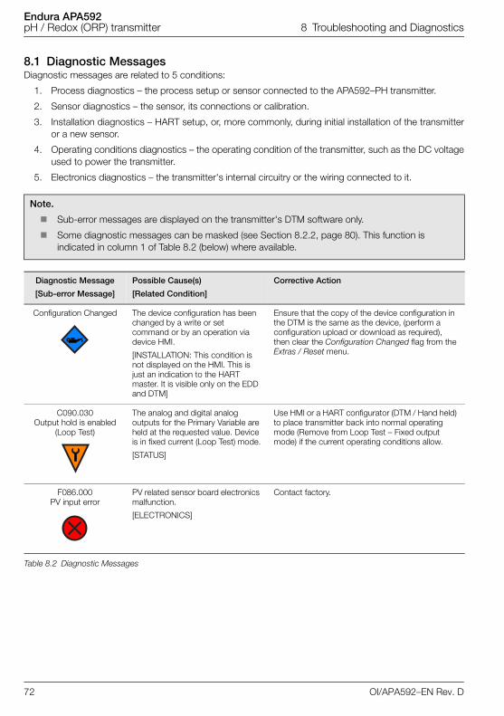
Endura APA592pH / Redox (ORP) transmitter 8 Troubleshooting and Diagnostics
8.1 Diagnostic MessagesDiagnostic messages are related to 5 conditions:
1. Process diagnostics – the process setup or sensor connected to the APA592–PH transmitter.
2. Sensor diagnostics – the sensor, its connections or calibration.
3. Installation diagnostics – HART setup, or, more commonly, during initial installation of the transmitteror a new sensor.
4. Operating conditions diagnostics – the operating condition of the transmitter, such as the DC voltageused to power the transmitter.
5. Electronics diagnostics – the transmitter's internal circuitry or the wiring connected to it.
Note.
Sub-error messages are displayed on the transmitter's DTM software only.
Some diagnostic messages can be masked (see Section 8.2.2, page 80). This function is indicated in column 1 of Table 8.2 (below) where available.
Diagnostic Message
[Sub-error Message]
Possible Cause(s)
[Related Condition]
Corrective Action
Configuration Changed The device configuration has been changed by a write or set command or by an operation via device HMI.
[INSTALLATION: This condition is not displayed on the HMI. This is just an indication to the HART master. It is visible only on the EDD and DTM]
Ensure that the copy of the device configuration in the DTM is the same as the device, (perform a configuration upload or download as required), then clear the Configuration Changed flag from the Extras / Reset menu.
C090.030Output hold is enabled
(Loop Test)
The analog and digital analog outputs for the Primary Variable are held at the requested value. Device is in fixed current (Loop Test) mode.
[STATUS]
Use HMI or a HART configurator (DTM / Hand held) to place transmitter back into normal operating mode (Remove from Loop Test – Fixed output mode) if the current operating conditions allow.
F086.000PV input error
PV related sensor board electronics malfunction.
[ELECTRONICS]
Contact factory.
Table 8.2 Diagnostic Messages
72 OI/APA592–EN Rev. D
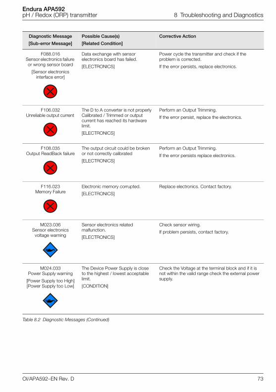
Endura APA592pH / Redox (ORP) transmitter 8 Troubleshooting and Diagnostics
F088.016Sensor electronics failure or wrong sensor board
[Sensor electronics interface error]
Data exchange with sensor electronics board has failed.
[ELECTRONICS]
Power cycle the transmitter and check if the problem is corrected.
If the error persists, replace electronics.
F106.032Unreliable output current
The D to A converter is not properly Calibrated / Trimmed or output current has reached its hardware limit.
[ELECTRONICS]
Perform an Output Trimming.
If the error persist, replace the electronics.
F108.035Output ReadBack failure
The output circuit could be broken or not correctly calibrated
[ELECTRONICS]
Perform an Output Trimming.
If the error persists replace electronics.
F116.023Memory Failure
Electronic memory corrupted.
[ELECTRONICS]
Replace electronics. Contact factory.
M023.036Sensor electronics
voltage warning
Sensor electronics related malfunction.
[ELECTRONICS]
Check sensor wiring.
If problem persists, contact factory.
M024.033Power Supply warning
[Power Supply too High][Power Supply too Low]
The Device Power Supply is close to the highest / lowest acceptable limit.
[CONDITION]
Check the Voltage at the terminal block and if it is not within the valid range check the external power supply.
Diagnostic Message
[Sub-error Message]
Possible Cause(s)
[Related Condition]
Corrective Action
Table 8.2 Diagnostic Messages (Continued)
OI/APA592–EN Rev. D 73
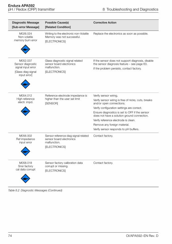
Endura APA592pH / Redox (ORP) transmitter 8 Troubleshooting and Diagnostics
M026.024Non-volatile
memory burn error
Writing to the electronic non-Volatile Memory was not successful.
[ELECTRONICS]
Replace the electronics as soon as possible.
M052.037Sensor diagnostic signal input error
[Glass diag signal input error]
Glass diagnostic signal related sensor board electronics malfunction.
[ELECTRONICS]
If the sensor does not support diagnosis, disable the sensor diagnosis feature – see page 63.
If the problem persists, contact factory.
M054.012High reference electr. impd.
Reference electrode impedance is higher than the user set limit
[SENSOR]
Verify sensor wiring.
Verify sensor wiring is free of nicks, cuts, breaks and/or open connections.
Verify configuration settings are correct.
Ensure diagnostics is set to OFF if the sensor does not have a solution ground connection.
Verify reference electrode is clean.
Remove any foreign material.
Verify sensor responds to pH buffers.
M056.002Ref impedance
input error
Sensor reference diag signal related sensor board electronics malfunction.
[ELECTRONICS]
Contact factory.
M058.018Snsr factory
cal data corrupt
Sensor factory calibration data corrupt or missing.
[ELECTRONICS]
Contact factory.
Diagnostic Message
[Sub-error Message]
Possible Cause(s)
[Related Condition]
Corrective Action
Table 8.2 Diagnostic Messages (Continued)
74 OI/APA592–EN Rev. D
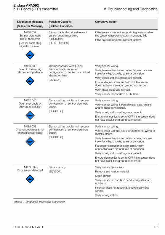
Endura APA592pH / Redox (ORP) transmitter 8 Troubleshooting and Diagnostics
M060.037Sensor diagnostic signal input error
[Sensor cable diag signal input error]
Sensor cable diag signal related sensor board electronics malfunction.
[ELECTRONICS]
If the sensor does not support diagnosis, disable the sensor diagnosis feature – see page 63.
If the problem persists, contact factory.
M080.039Low pH measuring
electrode impedance
Improper sensor wiring, dirty terminal block, improper configuration or broken or cracked electrode glass.
[SENSOR]
Verify sensor wiring.
Verify terminal blocks and other connections are free of any liquids, oils, scale or corrosion.
Verify configuration settings are correct.
Ensure diagnostics is set to OFF if the sensor does not have a solution ground connection.
Verify glass electrode is intact.
Verify sensor responds to pH buffers.
M082.040Open snsr cable or snsr out of solution
Sensor wiring problems, improper configuration of sensor diagnosis option.
[PROCESS]
Verify sensor wiring.
Verify sensor wiring is free of nicks, cuts, breaks and/or open connections.
Verify configuration settings are correct.
Ensure diagnostics is set to OFF if the sensor does not have a solution ground connection.
M084.038Ground loops present or
shorted sensor cable
Sensor wiring problems, improper configuration of sensor diagnosis option.
[PROCESS]
Verify sensor wiring.
Verify sensor wiring is not shorted to other wiring or metal surfaces.
Verify terminal blocks and other connections are free of any liquids, oils, scale or corrosion.
If a sensor extension is being used, verify connections are dry and free of corrosion.
Verify configuration settings are correct.
Ensure diagnostics is set to OFF if the sensor does not have a solution ground connection.
M089.039Dirty sensor detected
Sensor is dirty.
[SENSOR]
Verify sensor tip is clean.
Remove any foreign material.
Clean sensor.
Verify sensor responds to conductivity standard solutions.
If sensor does not respond, electronically test sensor.
Verify configuration.
Diagnostic Message
[Sub-error Message]
Possible Cause(s)
[Related Condition]
Corrective Action
Table 8.2 Diagnostic Messages (Continued)
OI/APA592–EN Rev. D 75
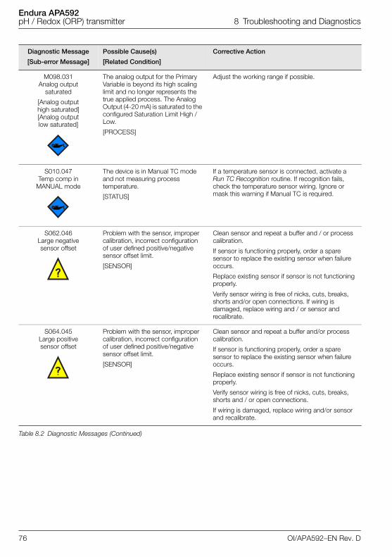
Endura APA592pH / Redox (ORP) transmitter 8 Troubleshooting and Diagnostics
M098.031Analog output
saturated
[Analog output high saturated][Analog output low saturated]
The analog output for the Primary Variable is beyond its high scaling limit and no longer represents the true applied process. The Analog Output (4-20 mA) is saturated to the configured Saturation Limit High / Low.
[PROCESS]
Adjust the working range if possible.
S010.047Temp comp in
MANUAL mode
The device is in Manual TC mode and not measuring process temperature.
[STATUS]
If a temperature sensor is connected, activate a Run TC Recognition routine. If recognition fails, check the temperature sensor wiring. Ignore or mask this warning if Manual TC is required.
S062.046Large negative sensor offset
Problem with the sensor, improper calibration, incorrect configuration of user defined positive/negative sensor offset limit.
[SENSOR]
Clean sensor and repeat a buffer and / or process calibration.
If sensor is functioning properly, order a spare sensor to replace the existing sensor when failure occurs.
Replace existing sensor if sensor is not functioning properly.
Verify sensor wiring is free of nicks, cuts, breaks, shorts and/or open connections. If wiring is damaged, replace wiring and / or sensor and recalibrate.
S064.045Large positive sensor offset
Problem with the sensor, improper calibration, incorrect configuration of user defined positive/negative sensor offset limit.
[SENSOR]
Clean sensor and repeat a buffer and/or process calibration.
If sensor is functioning properly, order a spare sensor to replace the existing sensor when failure occurs.
Replace existing sensor if sensor is not functioning properly.
Verify sensor wiring is free of nicks, cuts, breaks, shorts and / or open connections.
If wiring is damaged, replace wiring and/or sensor and recalibrate.
Diagnostic Message
[Sub-error Message]
Possible Cause(s)
[Related Condition]
Corrective Action
Table 8.2 Diagnostic Messages (Continued)
76 OI/APA592–EN Rev. D
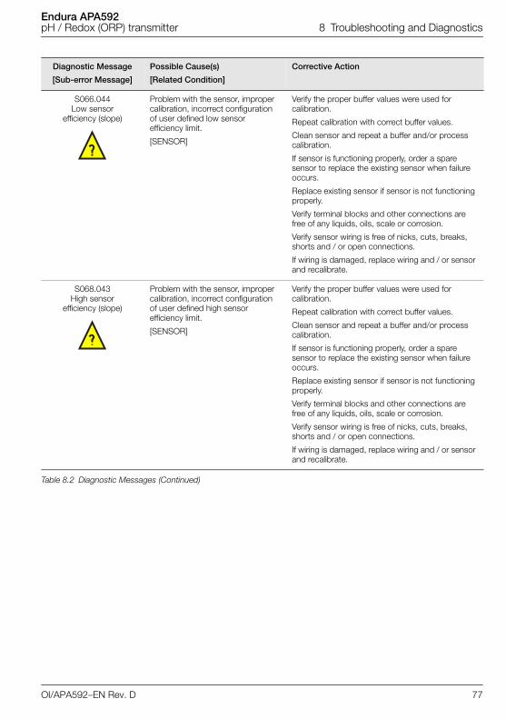
Endura APA592pH / Redox (ORP) transmitter 8 Troubleshooting and Diagnostics
S066.044Low sensor
efficiency (slope)
Problem with the sensor, improper calibration, incorrect configuration of user defined low sensor efficiency limit.
[SENSOR]
Verify the proper buffer values were used for calibration.
Repeat calibration with correct buffer values.
Clean sensor and repeat a buffer and/or process calibration.
If sensor is functioning properly, order a spare sensor to replace the existing sensor when failure occurs.
Replace existing sensor if sensor is not functioning properly.
Verify terminal blocks and other connections are free of any liquids, oils, scale or corrosion.
Verify sensor wiring is free of nicks, cuts, breaks, shorts and / or open connections.
If wiring is damaged, replace wiring and / or sensor and recalibrate.
S068.043High sensor
efficiency (slope)
Problem with the sensor, improper calibration, incorrect configuration of user defined high sensor efficiency limit.
[SENSOR]
Verify the proper buffer values were used for calibration.
Repeat calibration with correct buffer values.
Clean sensor and repeat a buffer and/or process calibration.
If sensor is functioning properly, order a spare sensor to replace the existing sensor when failure occurs.
Replace existing sensor if sensor is not functioning properly.
Verify terminal blocks and other connections are free of any liquids, oils, scale or corrosion.
Verify sensor wiring is free of nicks, cuts, breaks, shorts and / or open connections.
If wiring is damaged, replace wiring and / or sensor and recalibrate.
Diagnostic Message
[Sub-error Message]
Possible Cause(s)
[Related Condition]
Corrective Action
Table 8.2 Diagnostic Messages (Continued)
OI/APA592–EN Rev. D 77
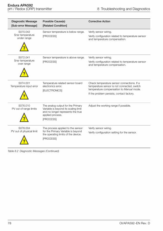
Endura APA592pH / Redox (ORP) transmitter 8 Troubleshooting and Diagnostics
S070.042Snsr temperature
under range
Sensor temperature is below range.
[PROCESS]
Verify sensor wiring.
Verify configuration related to temperature sensor and temperature compensation.
S072.041Snsr temperature
over range
Sensor temperature is above range.
[PROCESS]
Verify sensor wiring.
Verify configuration related to temperature sensor and temperature compensation.
S074.001Temperature input error
Temperature related sensor board electronics error.
[ELECTRONICS]
Check temperature sensor connections. If a temperature sensor is not connected, switch temperature compensation to Manual mode.
If the problem persists, contact factory.
S076.010PV out of range limits
The analog output for the Primary Variable is beyond its scaling limit and no longer represents the true applied process.
[PROCESS]
Adjust the working range if possible.
S078.004PV out of physical limit
The process applied to the sensor for the Primary Variable is beyond the operating limits of the device.
[PROCESS]
Verify sensor wiring.
Verify configuration setting for the sensor.
Diagnostic Message
[Sub-error Message]
Possible Cause(s)
[Related Condition]
Corrective Action
Table 8.2 Diagnostic Messages (Continued)
78 OI/APA592–EN Rev. D
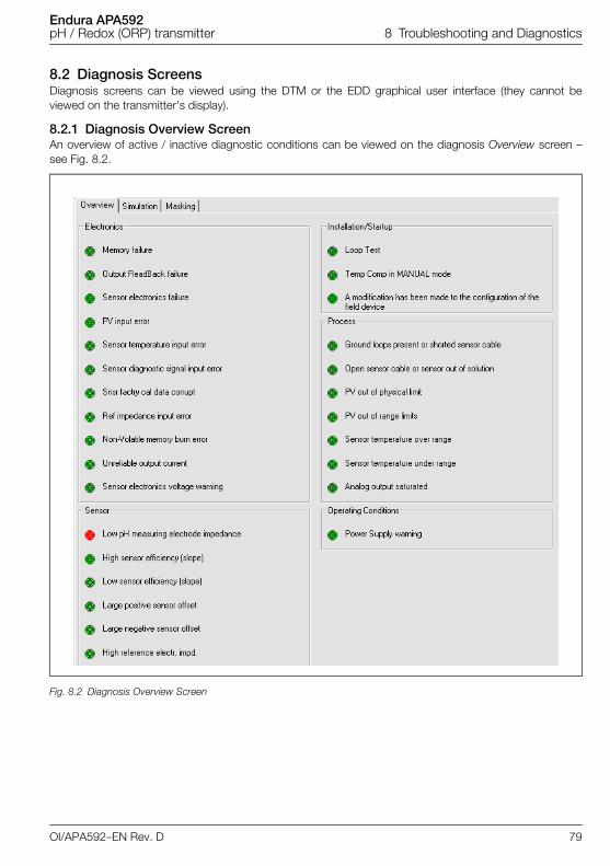
Endura APA592pH / Redox (ORP) transmitter 8 Troubleshooting and Diagnostics
8.2 Diagnosis ScreensDiagnosis screens can be viewed using the DTM or the EDD graphical user interface (they cannot beviewed on the transmitter's display).
8.2.1 Diagnosis Overview ScreenAn overview of active / inactive diagnostic conditions can be viewed on the diagnosis Overview screen –see Fig. 8.2.
Fig. 8.2 Diagnosis Overview Screen
OI/APA592–EN Rev. D 79
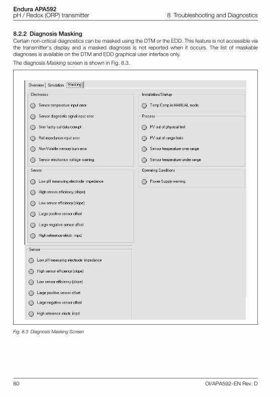
Endura APA592pH / Redox (ORP) transmitter 8 Troubleshooting and Diagnostics
8.2.2 Diagnosis MaskingCertain non-critical diagnostics can be masked using the DTM or the EDD. This feature is not accessible viathe transmitter's display and a masked diagnosis is not reported when it occurs. The list of maskablediagnoses is available on the DTM and EDD graphical user interface only.
The diagnosis Masking screen is shown in Fig. 8.3.
Fig. 8.3 Diagnosis Masking Screen
80 OI/APA592–EN Rev. D
Endura APA592pH / Redox (ORP) transmitter 8 Troubleshooting and Diagnostics
8.2.3 Diagnosis SimulationAll diagnosis conditions except Loop test (see page 72) can be simulated individually using the DTM orEDD.
To simulate a diagnosis, turn diagnosis simulation ON, select a diagnosis and send it to the transmitter. InSimulated Diagnosis mode, all active diagnoses are suppressed and only the simulated diagnosis isreported.
Diagnosis simulation status can be viewed on the HMI using Diagnostics / Diagnosis Status menu (seeSection 7.3.6, page 68). The status is either Simulated or Actual (diagnosis simulation cannot be set orcleared from the HMI.
Caution.
Diagnosis simulation cannot be performed via the transmitter's display.
Diagnosis simulation should be used for advanced test purposes only.
Diagnosis simulation is volatile – simulation setting is lost after a power-up.
OI/APA592–EN Rev. D 81
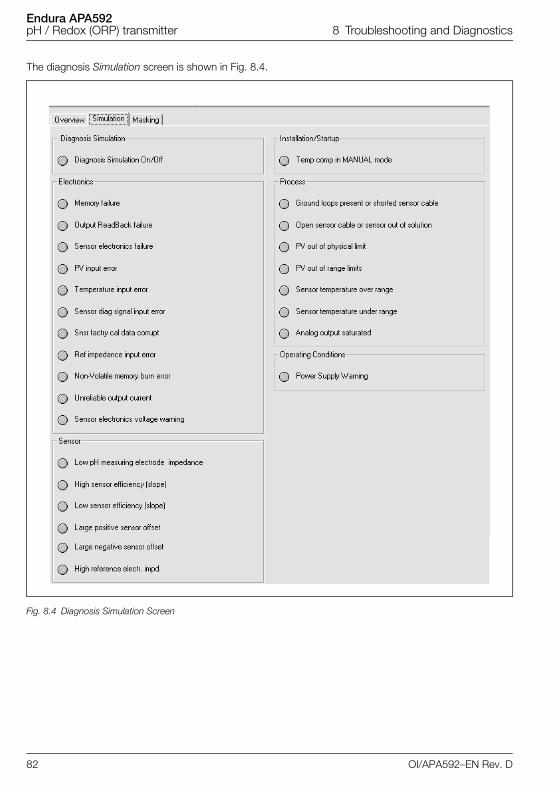
Endura APA592pH / Redox (ORP) transmitter 8 Troubleshooting and Diagnostics
The diagnosis Simulation screen is shown in Fig. 8.4.
Fig. 8.4 Diagnosis Simulation Screen
82 OI/APA592–EN Rev. D
Endura APA592pH / Redox (ORP) transmitter 9 HART Communication
9 HART CommunicationFor ease of identification, each HART device features a configurable 8-character HART tag. In addition tothe HART tag, each device has a HART address (set to the default value 0). At this address, the deviceoperates in HART standard communication mode (point-to-point operation).
When an address in the range 1 to 15 is used, the device switches to HART multidrop mode. Thisoperating mode enables users to connect up to 15 devices in parallel to a power supply.
In multidrop mode, an analog output signal that matches the Primary Value is not available. The outputsignal in multidrop mode is basically a constant 4 mA and is used exclusively for the power supply. Inmultidrop mode, sensor or process data information is available as a HART signal only.
In addition to point-to-point and multidrop modes, the third type of HART communication is burst mode.When Burst Mode is activated, the device transmits a HART telegram continuously, containing processinformation approximately every 500 ms without prompting by a HART command – refer to page 69 forfurther details of Burst Mode.
9.1 HART Device Type CodesAll HART products contain unique identifiers that specify the device type.
The device type code for APA592-PH is 48 (30 hex) under manufacturer type code 26 (1A hex).
OI/APA592–EN Rev. D 83
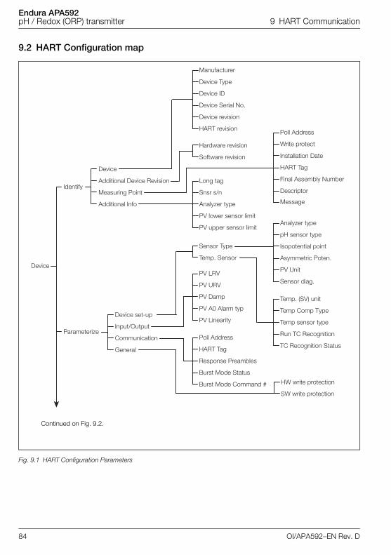
Endura APA592pH / Redox (ORP) transmitter 9 HART Communication
9.2 HART Configuration map
Fig. 9.1 HART Configuration Parameters
Device
Identify
Device Serial No.
Device revision
HART revision
Hardware revision
Software revision
Device ID
Device Type
Manufacturer
Additional Info
Measuring Point
Additional Device Revision
Device
Parameterize
HART Tag
Final Assembly Number
Descriptor
Message
Installation Date
Write protect
Poll Address
Asymmetric Poten.
PV Unit
Sensor diag.
Isopotential point
pH sensor type
Analyzer type
Run TC Recognition
TC Recognition Status
Temp sensor type
Temp Comp Type
Temp. (SV) unit
PV A0 Alarm typ
PV Linearity
PV Damp
PV URV
PV LRV
Burst Mode Status
Burst Mode Command #
Response Preambles
HART Tag
Poll Address
PV lower sensor limit
PV upper sensor limit
Analyzer type
Snsr s/n
Long tag
Sensor Type
Temp. Sensor
HW write protection
SW write protection
General
Communication
Input/Output
Device set-up
Continued on Fig. 9.2.
84 OI/APA592–EN Rev. D
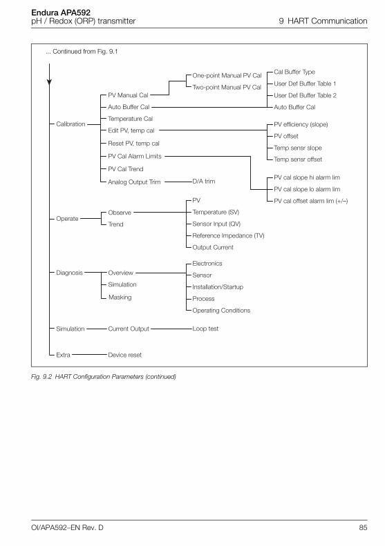
Endura APA592pH / Redox (ORP) transmitter 9 HART Communication
Fig. 9.2 HART Configuration Parameters (continued)
Calibration
Operate
Diagnosis
Simulation
Extra
User Def Buffer Table 2
Auto Buffer Cal
User Def Buffer Table 1
Cal Buffer Type
Temp sensr slope
Temp sensr offset
PV offset
PV efficiency (slope)
PV cal offset alarm lim (+/–)
PV cal slope lo alarm lim
PV cal slope hi alarm lim
Reference Impedance (TV)
Output Current
Sensor Input (QV)
Temperature (SV)
PV
Process
Operating Conditions
Loop test
Installation/Startup
Sensor
Electronics
One-point Manual PV Cal
Two-point Manual PV Cal
Trend
Observe
Simulation
Overview
Masking
D/A trim
Current Output
Device reset
Edit PV, temp cal
Temperature Cal
Auto Buffer Cal
PV Manual Cal
Reset PV, temp cal
PV Cal Alarm Limits
PV Cal Trend
Analog Output Trim
... Continued from Fig. 9.1
OI/APA592–EN Rev. D 85
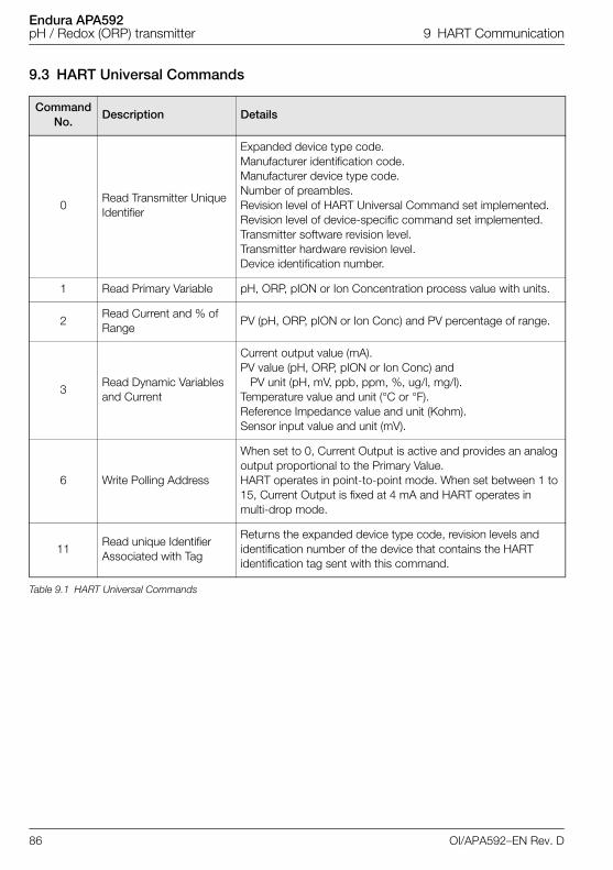
Endura APA592pH / Redox (ORP) transmitter 9 HART Communication
9.3 HART Universal Commands
Command No.
Description Details
0Read Transmitter Unique Identifier
Expanded device type code.Manufacturer identification code.Manufacturer device type code.Number of preambles.Revision level of HART Universal Command set implemented.Revision level of device-specific command set implemented.Transmitter software revision level.Transmitter hardware revision level.Device identification number.
1 Read Primary Variable pH, ORP, pION or Ion Concentration process value with units.
2Read Current and % of Range
PV (pH, ORP, pION or Ion Conc) and PV percentage of range.
3Read Dynamic Variables and Current
Current output value (mA).PV value (pH, ORP, pION or Ion Conc) and
PV unit (pH, mV, ppb, ppm, %, ug/l, mg/l).Temperature value and unit (°C or °F).Reference Impedance value and unit (Kohm).Sensor input value and unit (mV).
6 Write Polling Address
When set to 0, Current Output is active and provides an analog output proportional to the Primary Value.HART operates in point-to-point mode. When set between 1 to 15, Current Output is fixed at 4 mA and HART operates in multi-drop mode.
11Read unique Identifier Associated with Tag
Returns the expanded device type code, revision levels and identification number of the device that contains the HART identification tag sent with this command.
Table 9.1 HART Universal Commands
86 OI/APA592–EN Rev. D
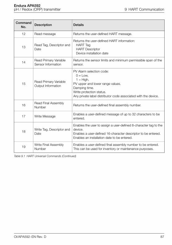
Endura APA592pH / Redox (ORP) transmitter 9 HART Communication
12 Read message Returns the user-defined HART message.
13Read Tag, Descriptor and Date
Returns the user-defined HART information:HART TagHART DescriptorDevice installation date
14Read Primary Variable Sensor Information
Returns the sensor limits and minimum permissible span of the sensor.
15Read Primary Variable Output Information
PV Alarm selection code:0 = Low,1 = High,
PV upper and lower range values.Damping time.Write protection status.Any private label distributor code associated with the device.
16Read Final Assembly Number
Returns the user-defined final assembly number.
17 Write MessageEnables a user-defined message of up to 32 characters to be entered.
18Write Tag, Descriptor and Date
Enables the user to assign a user-defined 8-character tag to the device.Enables a user-defined 16-character descriptor to be entered.Enables an installation date to be entered.
19Write Final Assembly Number
Enables a user-defined final assembly number to be entered.This can be used for inventory or maintenance purposes.
Command No.
Description Details
Table 9.1 HART Universal Commands (Continued)
OI/APA592–EN Rev. D 87
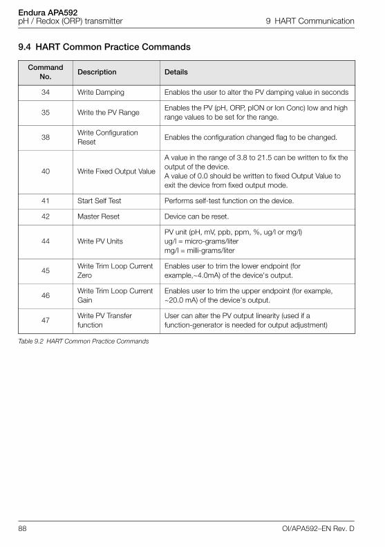
Endura APA592pH / Redox (ORP) transmitter 9 HART Communication
9.4 HART Common Practice Commands
Command No.
Description Details
34 Write Damping Enables the user to alter the PV damping value in seconds
35 Write the PV RangeEnables the PV (pH, ORP, pION or Ion Conc) low and high range values to be set for the range.
38Write Configuration Reset
Enables the configuration changed flag to be changed.
40 Write Fixed Output Value
A value in the range of 3.8 to 21.5 can be written to fix the output of the device.A value of 0.0 should be written to fixed Output Value to exit the device from fixed output mode.
41 Start Self Test Performs self-test function on the device.
42 Master Reset Device can be reset.
44 Write PV UnitsPV unit (pH, mV, ppb, ppm, %, ug/l or mg/l)ug/l = micro-grams/litermg/l = milli-grams/liter
45Write Trim Loop Current Zero
Enables user to trim the lower endpoint (for example,~4.0mA) of the device's output.
46Write Trim Loop Current Gain
Enables user to trim the upper endpoint (for example, ~20.0 mA) of the device's output.
47Write PV Transfer function
User can alter the PV output linearity (used if a function-generator is needed for output adjustment)
Table 9.2 HART Common Practice Commands
88 OI/APA592–EN Rev. D
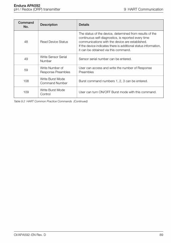
Endura APA592pH / Redox (ORP) transmitter 9 HART Communication
48 Read Device Status
The status of the device, determined from results of the continuous self-diagnostics, is reported every time communications with the device are established.If the device indicates there is additional status information, it can be obtained via this command.
49Write Sensor Serial Number
Sensor serial number can be entered.
59Write Number of Response Preambles
User can access and write the number of Response Preambles
108Write Burst Mode Command Number
Burst command numbers 1, 2, 3 can be entered.
109Write Burst Mode Control
User can turn ON/OFF Burst mode with this command.
Command No.
Description Details
Table 9.2 HART Common Practice Commands (Continued)
OI/APA592–EN Rev. D 89
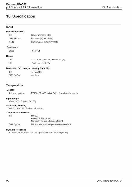
Endura APA592pH / Redox (ORP) transmitter 10 Specification
10 Specification
Input
Process Variable
Resistance
Range
Resolution / Accuracy / Linearity / Stability
Temperature
Sensor
Input Range–20 to 200 °C (–4 to 392 °F)
Accuracy / Stability+/– 0.1 °C (0.18 °F) after calibration
Compensation Modes
Dynamic Response<3 Seconds for 90 % step change at 0.00 second dampening
pH Glass, antimony (Sb)
ORP (Redox) Platinum (Pt), Gold (Au)
pION Custom user-programmable
Glass 1x10¹³
pH 0 to 14 pH (–2 to 16 pH over range)
ORP –1500 to +1500 mV
pH +/– 0.01pH
ORP / pION +/– 1mV
Auto-recognition PT100, PT1000, 3 k Balco 2- and 3-wire inputs
pH Manual,Automatic Nernstian,Nernstian with solution coefficient
ORP / pION Manual, solution compensation coefficient
90 OI/APA592–EN Rev. D
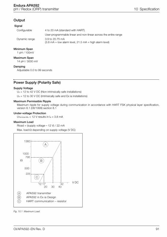
Endura APA592pH / Redox (ORP) transmitter 10 Specification
Output
Signal
Minimum Span1 pH / 100mV
Maximum Span14 pH / 3000 mV
DampingAdjustable 0.0 to 99 seconds
Power Supply (Polarity Safe)
Supply VoltageUs = 12 to 42 V DC (Non-intrinsically safe installations)
Us = 12 to 30 V DC (Intrinsically safe and Ex ia installations)
Maximum Permissible RippleMaximum ripple for supply voltage during communication in accordance with HART FSK physical layer specification,version 8.1 (08/1999) section 8.1
Under-voltage ProtectionUTerminal-Mu < 12 V results in Ia = 3.8 mA
Maximum LoadRload = (supply voltage – 12 V) / 22 mA
Max. load depending on supply voltage (V DC)
Configurable 4 to 20 mA (standard with HART)
User-programmable linear and non-linear across the entire range
Dynamic range 3.9 to 20.75 mA(3.8 mA = low alarm level, 21.5 mA = high alarm level)
Fig. 10.1 Maximum Load
���
����
����
���
���
�� �� ��
�
�
�
�� ����
�
�
�
V DC
A APA592 transmitterB APA592 in Ex ia DesignC HART communication – resistor
OI/APA592–EN Rev. D 91
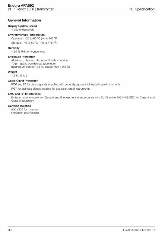
Endura APA592pH / Redox (ORP) transmitter 10 Specification
General Information
Display Update Speed< 250 milliseconds
Environmental (Temperature)Operating: –20 to 60 °C (–4 to 140 °F)
Storage: –40 to 80 °C (–40 to 176 °F)
Humidity< 95 % RH non-condensing
Enclosure ProtectionAluminum, die cast, chromized inside / outside, 70 µm epoxy powdercoat (aluminum, magnesium content < 6 %, copper-free < 0.5 %)
Weight1.3 Kg (3 lb.)
Cable Gland ProtectionIP66 and 67 for plastic glands supplied with general purpose / Intrinsically safe instruments.
IP67 for stainless glands required for explosion-proof instruments.
EMC and RF InterferenceEmission and immunity for Class A and B equipment in accordance with EU Directive 2004/108/EEC for Class A andClass B equipment
Galvanic Isolation900 V DC for 1 second(insulation test voltage)
92 OI/APA592–EN Rev. D
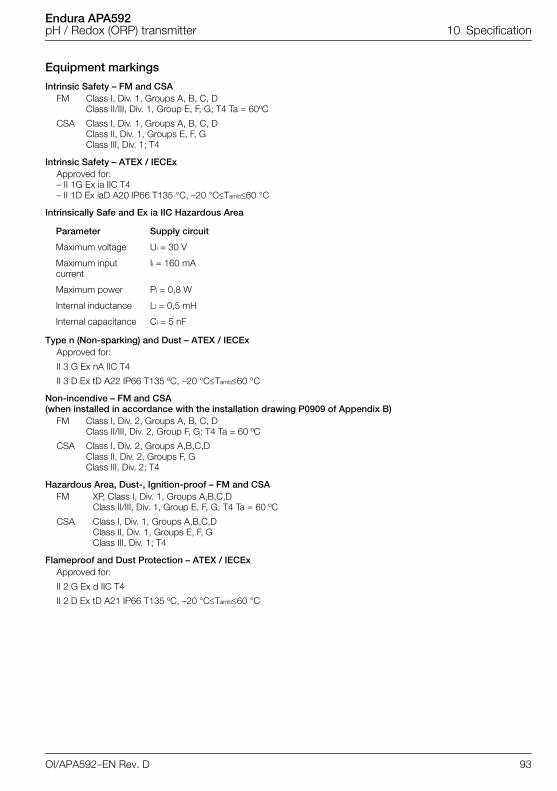
Endura APA592pH / Redox (ORP) transmitter 10 Specification
Equipment markings
Intrinsic Safety – FM and CSAFM Class I, Div. 1, Groups A, B, C, D
Class II/III, Div. 1, Group E, F, G; T4 Ta = 60ºC
CSA Class I, Div. 1, Groups A, B, C, DClass II, Div. 1, Groups E, F, GClass III, Div. 1; T4
Intrinsic Safety – ATEX / IECExApproved for:– II 1G Ex ia IIC T4– II 1D Ex iaD A20 IP66 T135 °C, –20 °CTamb60 °C
Intrinsically Safe and Ex ia IIC Hazardous Area
Type n (Non-sparking) and Dust – ATEX / IECExApproved for:
II 3 G Ex nA IIC T4
II 3 D Ex tD A22 IP66 T135 ºC, –20 °CTamb60 °C
Non-incendive – FM and CSA(when installed in accordance with the installation drawing P0909 of Appendix B)
FM Class I, Div. 2, Groups A, B, C, DClass II/III, Div. 2, Group F, G; T4 Ta = 60 ºC
CSA Class I, Div. 2, Groups A,B,C,DClass II, Div. 2, Groups F, GClass III, Div. 2; T4
Hazardous Area, Dust-, Ignition-proof – FM and CSAFM XP, Class I, Div. 1, Groups A,B,C,D
Class II/III, Div. 1, Group E, F, G; T4 Ta = 60 ºC
CSA Class I, Div. 1, Groups A,B,C,DClass II, Div. 1, Groups E, F, GClass III, Div. 1; T4
Flameproof and Dust Protection – ATEX / IECExApproved for:
II 2 G Ex d IIC T4
II 2 D Ex tD A21 IP66 T135 ºC, –20 °CTamb60 °C
Parameter Supply circuit
Maximum voltage Ui = 30 V
Maximum input current
Ii = 160 mA
Maximum power Pi = 0,8 W
Internal inductance Li = 0,5 mH
Internal capacitance Ci = 5 nF
OI/APA592–EN Rev. D 93

Endura APA592pH / Redox (ORP) transmitter 10 Specification
Agency Enclosure RatingsIP66 and IP67
NEMA 4X
Approvals
CE MarkThe APA592–PH including type B LCD display / configuration software meets all requirements for the CE mark inaccordance with the applicable directives 2004/108/EC (EMC), 2006/95/EC (LVD) and 94/9/EC (ATEX).
DS/APA592-EN
94 OI/APA592–EN Rev. D
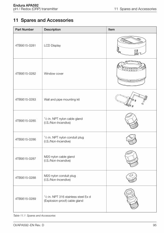
Endura APA592pH / Redox (ORP) transmitter 11 Spares and Accessories
11 Spares and Accessories
Part Number Description Item
4TB9515-0281 LCD Display
4TB9515-0282 Window cover
4TB9515-0283 Wall and pipe mounting kit
4TB9515-02851/2 in. NPT nylon cable gland(I.S./Non-Incendive)
4TB9515-02861/2 in. NPT nylon conduit plug(I.S./Non-Incendive)
4TB9515-0287M20 nylon cable gland(I.S./Non-Incendive)
4TB9515-0288M20 nylon conduit plug(I.S./Non-Incendive)
4TB9515-02891/2 in. NPT 316 stainless steel Ex d (Explosion-proof) cable gland
Table 11.1 Spares and Accessories
OI/APA592–EN Rev. D 95
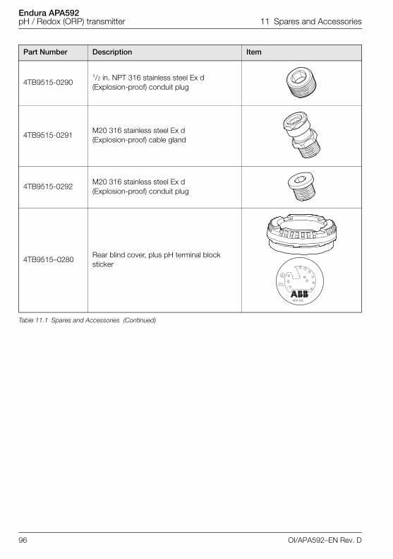
Endura APA592pH / Redox (ORP) transmitter 11 Spares and Accessories
4TB9515-02901/2 in. NPT 316 stainless steel Ex d (Explosion-proof) conduit plug
4TB9515-0291M20 316 stainless steel Ex d (Explosion-proof) cable gland
4TB9515-0292M20 316 stainless steel Ex d (Explosion-proof) conduit plug
4TB9515–0280Rear blind cover, plus pH terminal block sticker
Part Number Description Item
Table 11.1 Spares and Accessories (Continued)
APA 592
96 OI/APA592–EN Rev. D
Endura APA592pH / Redox (ORP) transmitter Appendix A
Appendix A
A.1 Permits and Certification
A.2 Temperature CompensationThe Endura APA592 transmitter has three types of temperature compensation options:
manual Nernstian.
automatic Nernstian with solution coefficient
The temperature effect on ORP sensors is negligible. The effect of temperature on pION sensors is difficultto characterize, except for specific applications. Therefore, only the solution coefficient option can be usedto compensate for electrode and process changes with temperature.
Symbol Description
Explosion-proofapproval
The Ex label indicates a device that complies with the directive 94/9/EC
CE mark
The CE mark indicates that the device complies with the following directives and their basic safety requirements:
CE mark on the name plate of transmitter
– EMC directive 2004/108/EC, Low Voltage directive 2006/95/EC, ATEX directive 94/9/EC
For ignition-protection applications:
– Conforms with hazardous area directive 94/9/EC (ATEX 95)
By placing the CE mark on its devices, ABB declares its conformance with these directives.
Table A.1 Permits and Certification
OI/APA592–EN Rev. D 97
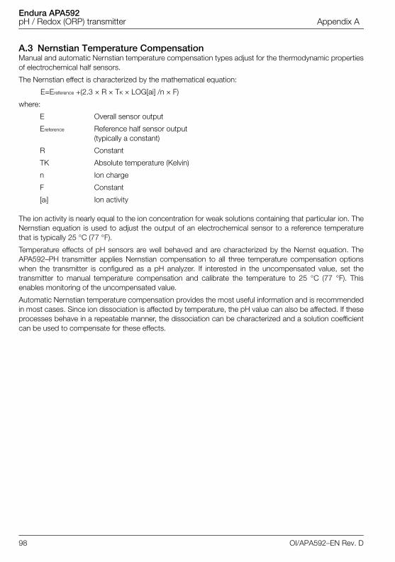
Endura APA592pH / Redox (ORP) transmitter Appendix A
A.3 Nernstian Temperature CompensationManual and automatic Nernstian temperature compensation types adjust for the thermodynamic propertiesof electrochemical half sensors.
The Nernstian effect is characterized by the mathematical equation:
E=Ereference +(2.3 × R × TK × LOG[ai] /n × F)
where:
E Overall sensor output
Ereference Reference half sensor output (typically a constant)
R Constant
TK Absolute temperature (Kelvin)
n Ion charge
F Constant
[ai] Ion activity
The ion activity is nearly equal to the ion concentration for weak solutions containing that particular ion. TheNernstian equation is used to adjust the output of an electrochemical sensor to a reference temperaturethat is typically 25 °C (77 °F).
Temperature effects of pH sensors are well behaved and are characterized by the Nernst equation. TheAPA592–PH transmitter applies Nernstian compensation to all three temperature compensation optionswhen the transmitter is configured as a pH analyzer. If interested in the uncompensated value, set thetransmitter to manual temperature compensation and calibrate the temperature to 25 °C (77 °F). Thisenables monitoring of the uncompensated value.
Automatic Nernstian temperature compensation provides the most useful information and is recommendedin most cases. Since ion dissociation is affected by temperature, the pH value can also be affected. If theseprocesses behave in a repeatable manner, the dissociation can be characterized and a solution coefficientcan be used to compensate for these effects.
98 OI/APA592–EN Rev. D
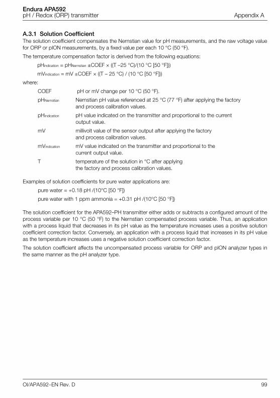
Endura APA592pH / Redox (ORP) transmitter Appendix A
A.3.1 Solution CoefficientThe solution coefficient compensates the Nernstian value for pH measurements, and the raw voltage valuefor ORP or pION measurements, by a fixed value per each 10 °C (50 °F).
The temperature compensation factor is derived from the following equations:
pHindication = pHNernstian ±COEF × ((T –25 °C)/(10 °C [50 °F]))
mVindication = mV ±COEF × ((T – 25 °C) / (10 °C [50 °F]))
where:
COEF pH or mV change per 10 °C (50 °F).
pHNernstian Nernstian pH value referenced at 25 °C (77 °F) after applying the factoryand process calibration values.
pHindication pH value indicated on the transmitter and proportional to the current output value.
mV millivolt value of the sensor output after applying the factory and process calibration values.
mVindication mV value indicated on the transmitter and proportional to the current output value.
T temperature of the solution in °C after applying the factory and process calibration values.
Examples of solution coefficients for pure water applications are:
pure water = +0.18 pH /(10°C [50 °F])
pure water with 1 ppm ammonia = +0.31 pH /(10°C [50 °F])
The solution coefficient for the APA592–PH transmitter either adds or subtracts a configured amount of theprocess variable per 10 °C (50 °F) to the Nernstian compensated process variable. Thus, an applicationwith a process liquid that decreases in its pH value as the temperature increases uses a positive solutioncoefficient correction factor. Conversely, an application with a process liquid that increases in its pH valueas the temperature increases uses a negative solution coefficient correction factor.
The solution coefficient affects the uncompensated process variable for ORP and pION analyzer types inthe same manner as the pH analyzer type.
OI/APA592–EN Rev. D 99
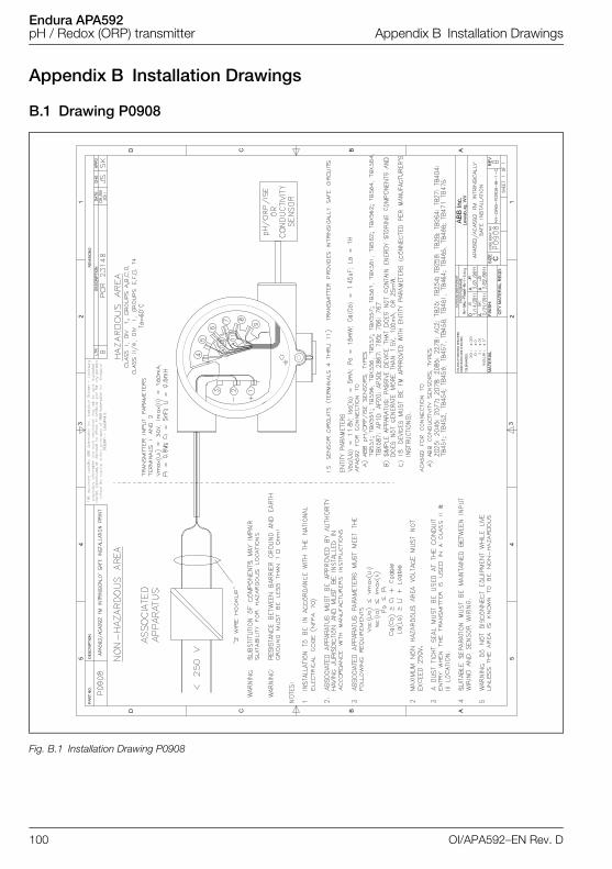
Endura APA592pH / Redox (ORP) transmitter Appendix B Installation Drawings
Appendix B Installation Drawings
B.1 Drawing P0908
Fig. B.1 Installation Drawing P0908
100 OI/APA592–EN Rev. D
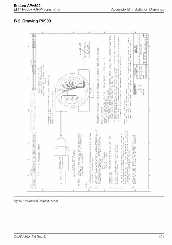
Endura APA592pH / Redox (ORP) transmitter Appendix B Installation Drawings
B.2 Drawing P0909
Fig. B.2 Installation Drawing P0909
OI/APA592–EN Rev. D 101
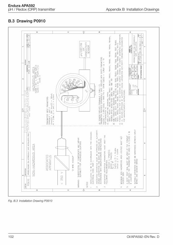
Endura APA592pH / Redox (ORP) transmitter Appendix B Installation Drawings
B.3 Drawing P0910
Fig. B.3 Installation Drawing P0910
102 OI/APA592–EN Rev. D
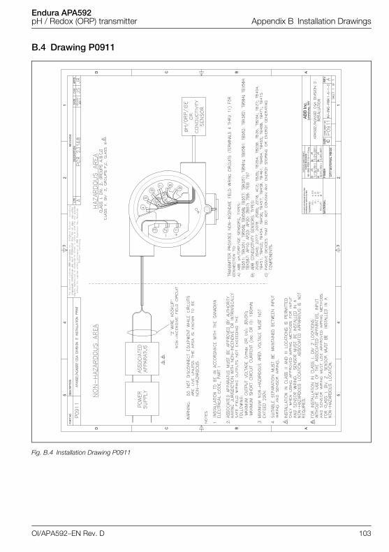
Endura APA592pH / Redox (ORP) transmitter Appendix B Installation Drawings
B.4 Drawing P0911
Fig. B.4 Installation Drawing P0911
OI/APA592–EN Rev. D 103

Endura APA592pH / Redox (ORP) transmitter Notes
Notes
104 OI/APA592–EN Rev. D
Products and customer support
Automation SystemsFor the following industries:— Chemical & Pharmaceutical— Food & Beverage— Manufacturing— Metals and Minerals— Oil, Gas & Petrochemical— Pulp and Paper
Drives and Motors— AC and 6 Drives, AC and DC Machines, AC Motors to
1kV— Drive Systems— Force Measurement— Servo Drives
Controllers & Recorders— Single and Multi-loop Controllers— Circular Chart and Strip Chart Recorders— Paperless Recorders— Process Indicators
Flexible Automation— Industrial Robots and Robot Systems
Flow Measurement— Electromagnetic Flowmeters— Mass Flowmeters— Turbine Flowmeters— Wedge Flow Elements
Marine Systems & Turbochargers— Electrical Systems— Marine Equipment— Offshore Retrofit and Refurbishment
Process Analytics— Process Gas Analysis— Systems Integration
Transmitters— Pressure— Temperature— Level— Interface Modules
Valves, Actuators and Positioners— Control Valves— Actuators— Positioners
Water, Gas & Industrial Analytics Instrumentation— pH, Conductivity and Dissolved Oxygen Transmitters
and Sensors— Ammonia, Nitrate, Phosphate, Silica, Sodium,
Chloride, Fluoride, Dissolved Oxygen and Hydrazine Analyzers
— Zirconia Oxygen Analyzers, Katharometers, Hydrogen Purity and Purge-gas Monitors, Thermal Conductivity
Customer supportWe provide a comprehensive after sales service via a Worldwide Service Organization. Contact one of the following offices for details on your nearest Service and Repair Centre.
UKABB LimitedTel: +44 (0)1453 826661Fax: +44 (0)1453 829671
USAABB Inc.Tel: +1 800-HELP-365 (+1 800-435-7365)
Client WarrantyPrior to installation, the equipment referred to in this manual must be stored in a clean, dry environment, in accordance with the Company's published specification.Periodic checks must be made on the equipment's condition. In the event of a failure under warranty, the following documentation must be provided as substantiation:— A listing evidencing process operation and alarm
logs at time of failure.— Copies of all storage, installation, operating and
maintenance records relating to the alleged faulty unit.
Contact us
OI/A
PA59
2–E
N R
ev. D
06.2
013
ABB LimitedProcess Automation Oldends LaneStonehouseGloucestershire GL10 3TAUKTel: +44 1453 826 661Fax: +44 1453 829 671
ABB Inc.Process Automation843 N Jefferson StreetPO Box 831LewisburgWV 24901-9509USATel: +1 800-HELP-365Fax: +1 304 647 1862
ABB Engineering (Shanghai) Ltd.Process AutomationNo. 5, Lane 369, Chuangye Road201319, Shanghai, P.R. ChinaPhone: +86 (0) 21 6105 6666Fax: +86 (0) 21 6105 6992Mail: [email protected]
www.abb.com
NoteWe reserve the right to make technical changes or modify the contents of this document without prior notice. With regard to purchase orders, the agreed particulars shall prevail. ABB does not accept any responsibility whatsoever for potential errors or possible lack of information in this document.
We reserve all rights in this document and in the subject matter and illustrations contained therein. Any reproduction, disclosure to third parties or utilization of its contents – in whole or in parts – is forbidden without prior written consent of ABB.
Copyright© 2013 ABBAll rights reserved
3KXA162592R4201
HART is a registered trademark of the HART Communication Foundation.Siemens is a copyright of Siemens AG.