NH3 Cross-Sensitivity of a NOX sensor and NH3 Measurements ...

Installation and Operation Manual
GG-NH3 AMMONIA GAS SENSOR

2 GG-NH3
Warning
Use this product only in the manner described in this manual.If the equipment is used in a manner not specified by Calibration
Technologies, the protection provided by the equipment may be impaired.
This equipment should be installed by qualified personnel.

GG-NH3 3
Table of ContentsGeneral Description . . . . . . . . . . . . . . . . . . . . . 4Installation . . . . . . . . . . . . . . . . . . . . . . . . . . . . . 4 Locating the Sensor . . . . . . . . . . . . . . . . . . . 4 Installation Guidelines . . . . . . . . . . . . . . . . . 5 Wiring . . . . . . . . . . . . . . . . . . . . . . . . . . . . . . . 6Operation . . . . . . . . . . . . . . . . . . . . . . . . . . . . . . 7 Start-Up . . . . . . . . . . . . . . . . . . . . . . . . . . . . . 7 Calibration . . . . . . . . . . . . . . . . . . . . . . . . . . . 7Maintenance . . . . . . . . . . . . . . . . . . . . . . . . . . . 9Specifications . . . . . . . . . . . . . . . . . . . . . . . . . . 10Warranty . . . . . . . . . . . . . . . . . . . . . . . . . . . . . . 11
For technical support, contact:
CTI920 N Tradewinds Pkwy
Columbia, MO 65201866-394-5861

4 GG-NH3General Description Installation
The GG-NH3 sensor is a +24 VDC, three-wire, 4/20 mA sensor for ammonia which utilizes proven electro-chemcial sensor technology for fast and accurate leak detection. The standard detection range of the GG-NH3 sensor provides real-time continuous monitoring of ammonia concentrations accurately down to 5 ppm without false alarms. CTI typically recommends a 0/100 ppm range for all personnel and product protection areas. Higher ranges (0/250, 0/500, 0/1000) are optional for higher alarm setpoint areas such as Engine Rooms.
The GG-NH3 sensor provides an industrial standard linear 4/20 mA output signal compatible with most gas detection systems and PLCs.
This sensor is equipped with SafeCell technology which checks the electrical viability of the electrochemical cell every 40 seconds. If it is determined that the cell is not electrically viable or missing, the fault (red) LED will blink once per second. After 6 hours of continued and consecutive test failures, the 4-20 mA signal output will drop to 0.5 mA and the fault LED stays on solid. This signal should be interpreted as a sensor fault at the control panel and prompt notification to plant personnel to investigate the sensor. Typically, the cell will need to be replaced once the SafeCell fault has occurred. Once the cell is replaced or found to be electrically viable, the fault condition will clear within 10 seconds.
Locating the sensorOne of the most important considerations when installing the GG-NH3 sensor is that it must be easily accessible for calibration and maintenance.
For optimum personnel protection (representative concentration reading that an employee would be exposed to), mount the sensor at a height in the breathing zone of the employees. It would typically be about five feet off the ground, which also allows easy access. As a general rule of thumb, try to mount sensors within 30 feet of potential leak sources.
Caution: Remove protective labelThe GG-NH3 sensor is shipped with a yellow label installed over the gas diffusion port of the electrochemical cell to preserve cell life. The cell will not detect ammonia vapors with this label installed. Remove label and discard during installation.
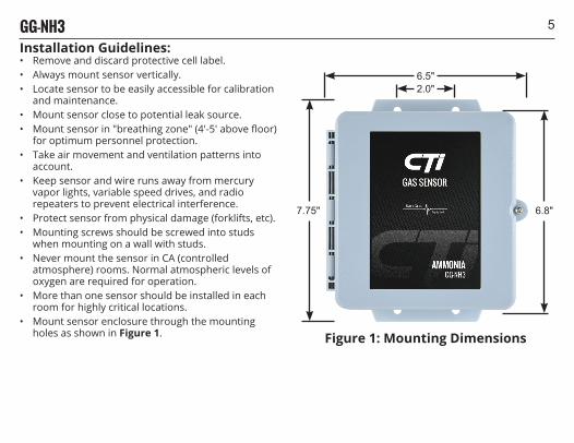
5GG-NH3Installation Guidelines:• Remove and discard protective cell label.• Always mount sensor vertically.• Locate sensor to be easily accessible for calibration
and maintenance.• Mount sensor close to potential leak source.• Mount sensor in "breathing zone" (4'-5' above floor)
for optimum personnel protection.• Take air movement and ventilation patterns into
account.• Keep sensor and wire runs away from mercury
vapor lights, variable speed drives, and radio repeaters to prevent electrical interference.
• Protect sensor from physical damage (forklifts, etc).• Mounting screws should be screwed into studs
when mounting on a wall with studs.• Never mount the sensor in CA (controlled
atmosphere) rooms. Normal atmospheric levels of oxygen are required for operation.
• More than one sensor should be installed in each room for highly critical locations.
• Mount sensor enclosure through the mounting holes as shown in Figure 1.
2.0"6.5"
6.8"7.75"
Figure 1: Mounting Dimensions
6 GG-NH3WiringElectrical wiring must comply with all applicable codes.
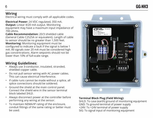
Electrical Power: 24 VDC regulated, 350 mA.Output: Linear 4/20 mA output. Monitoring equipment may have a maximum input impedance of 700 ohms.Cable Recommendation: 20/3 shielded cable (General Cable C2525A or equivalent). Length of cable to sensor should be no greater than 1,500 feet.Monitoring: Monitoring equipment must be configured to indicate a fault if the signal is below 1 mA. All signals over 20 mA must be considered high gas concentrations. Alarm setpoints should not be lower than 10% of full-scale range.
Wiring Guidelines:• Always use 3-conductor, insulated, stranded,
shielded copper cable.• Do not pull sensor wiring with AC power cables.
This can cause electrical interference.• If cable runs cannot be made without a splice, all
splice connections should be soldered.• Ground the shield at the main control panel.
Connect the shield wire in the sensor terminal block labeled SHLD.
• Always disconnect power at the controller before performing any wiring at the sensor.
• To maintain NEMA/IP rating of the enclosure, conduit fittings of the same rating or better must be used.
To signal input of monitoring equipmentTo +24V terminal of power supply
To ground terminal of power supplyTo case (earth) ground of monitoring equipment
Terminal Block Plug (Field Wiring):SHLD: To case (earth) ground of monitoring equipmentGND: To ground terminal of power supply+24V: To +24V terminal of power supplySIG: To signal input of monitoring equipment
7GG-NH3Operation
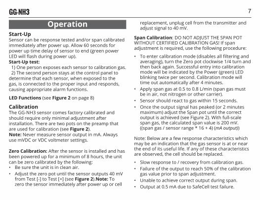
Start-UpSensor can be response tested and/or span calibrated immediately after power up. Allow 60 seconds for power up time delay of sensor to end (green power LED will flash during power up).Start-Up test: 1) One person exposes each sensor to calibration gas. 2) The second person stays at the control panel to determine that each sensor, when exposed to the gas, is connected to the proper input and responds, causing appropriate alarm functions.
LED Functions (see Figure 2 on page 8)
CalibrationThe GG-NH3 sensor comes factory calibrated and should require only minimal adjustment after installation. There are two pots on the preamp that are used for calibration (see Figure 2).Note: Never measure sensor output in mA. Always use mVDC or VDC voltmeter settings.
Zero Calibration: After the sensor is installed and has been powered up for a minimum of 8 hours, the unit can be zero calibrated by the following:• Be sure the unit is in clean air.• Adjust the zero pot until the sensor outputs 40 mV
from Test [-] to Test [+] (see Figure 2).Note: To zero the sensor immediately after power up or cell
replacement, unplug cell from the transmitter and adjust signal to 40 mV.
Span Calibration: DO NOT ADJUST THE SPAN POT WITHOUT CERTIFIED CALIBRATION GAS! If span adjustment is required, use the following procedure:
• To enter calibration mode (disables all filtering and averaging), turn the Zero pot clockwise 1/4 turn and then back again. Successful entry into calibration mode will be indicated by the Power (green) LED blinking twice per second. Calibration mode will time out automatically after 4 minutes.
• Apply span gas at 0.5 to 0.8 L/min (span gas must be in air, not nitrogen or other carrier).
• Sensor should react to gas within 15 seconds.• Once the output signal has peaked (or 2 minutes
maximum) adjust the Span pot until the correct output is achieved (see Figure 2). With full-scale span gas, the calculated span value is 200 mV. ((span gas / sensor range * 16 + 4) (mA output))
Note: Below are a few response characteristics which may be an indication that the gas sensor is at or near the end of its useful life. If any of these characteristics are observed, the cell should be replaced.
• Slow response to / recovery from calibration gas.• Failure of the output to reach 50% of the calibration
gas value prior to span adjustment.• Unable to achieve correct output during span.• Output at 0.5 mA due to SafeCell test failure.
8 GG-NH3
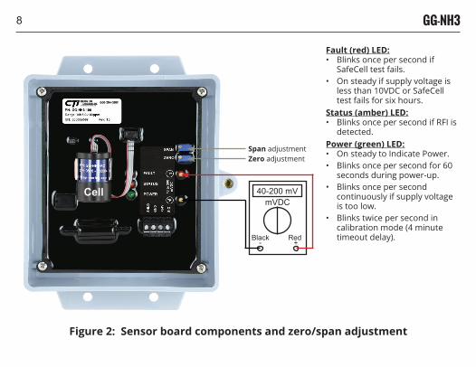
Figure 2: Sensor board components and zero/span adjustment
Span adjustmentZero adjustment
40-200 mVmVDC
Black Red- +
Fault (red) LED:• Blinks once per second if
SafeCell test fails.• On steady if supply voltage is
less than 10VDC or SafeCell test fails for six hours.
Status (amber) LED:• Blinks once per second if RFI is
detected.Power (green) LED:• On steady to Indicate Power.• Blinks once per second for 60
seconds during power-up.• Blinks once per second
continuously if supply voltage is too low.
• Blinks twice per second in calibration mode (4 minute timeout delay).
Cell
9GG-NH3
MaintenanceThe GG-NH3 sensor is designed for long life and minimal maintenance. For proper operation, it is essential that the test and calibration schedule be adhered to. Calibration Technologies recommends the following maintenance schedule:
Maintenance Guidelines:• The sensor is shipped with a factory calibration.• Sensor should be calibrated 6 months from
purchase date.• Calibrate the detector at least once every 6 months.• Calibration should be performed with certified
calibration gas. Calibration kits and replacement cylinders are available from CTI.
• All tests and calibrations must be logged.• Always disconnect power at the controller before
performing any wiring at the sensor.
Sensor Life: The electrochemical cells are extremely reliable, but several things can cause depletion of the chemistry within the cell including:
• A period of time• Exposure to high temperatures• Continuous, long term exposure to ammoniaWhen the SafeCell test fails, the fault (red) LED will blink once per second. After six hours of continued and consecutive test failures, the 4-20 mA signal output will drop to 0.5 mA and the fault LED stays on solid. This signal should be interpreted as a sensor fault at the control panel and prompt notification to plant personnel to investigate the sensor.
SafeCell technology tests the electrical viability of the cell, however, it does not confirm proper sensitivity to gas.There are other factors that could prevent the cell from detecting gas, such as physical blockage, etc. Therefore, it is absolutely essential that the sensor be calibrated every six months.
Typical cell life is 2 to 5 years. When the cell becomes depleted, a replacement cell can be obtained from CTI. Simply unplug the cell's ribbon cable from the transmitter, pull the old cell from the spring clip, discard the old cell and replace with a new one.
The new cell can be span-calibrated immediately. However, an 8 hour warm-up period is required before zeroing, if necessary.
Replacement cell order#: GG-NH3-RC
10 GG-NH3
SpecificationsInput Power: +24 VDC, 350 mADetection Principle: ElectrochemicalDetection Method: DiffusionGases: Ammonia (NH3)Ranges:0/100 (standard)0/2500/3000/5000/1000Custom ranges available. Call for more informationOutput Signal: Linear 4/20 mA (max input impedance: 700 Ohms)Response Time:T50 = less than 30 secondsT90 = less than 60 secondsAccuracy: +/- 5% of full-scale, but dependent on calibration gas accuracy and time since last calibrationZero Drift: Less than 0.1% of full-scale per month, non-cumulativeSpan Drift: Application dependent, but generally less than 3% per monthLinearity: +/- 0.5% of full-scaleRepeatability: +/- 1% of full scaleSafeCell Viability Check: Automatic electrical viability test of the electrochemical cell every 40 seconds. Failure of the test results in 0.5 mA output after 6 hours of continued and consecutive test failures.
Power (green) LED: Blinks once per second for 60 seconds during power-up. If supply voltage is too low (<10 VDC) or improperly grounded, green LED will blink once per second continuously. Stays steady on to indicate power. Blinks twice per second in calibration mode (4-minute timeout delay)Status (amber) LED: Blinks once per second if RFI (radio frequency interference) is detectedFault (red) LED: Stays on steady if supply voltage is too low (<10 VDC)Wiring Connections: 3-conductor, shielded, stranded, ≥ 20 AWG cable (General Cable C2525A or equivalent) up to 1500 ftTerminal Block Plug (Field Wiring): 26-12 AWG, torque 4.5 lbs-inEnclosure: Injection-molded, NEMA 3RX washdown-duty, polycarbonate sensor housing with hinged lid and captive screw. For non-classified areas. Optional 18 GA, NEMA 3RX washdown-duty stainless steel enclosure with hinged lid and captive screw. For non-classified areasTemperature Range: -50˚F to +122˚F (-46˚C to +50˚C)Humidity Range: 5% to 100% condensingDimensions: 7.7" high x 6.7: wide x 3.8" deepWeight: 3.0 lbsCertification: ETL Listed: Conforms to UL 61010-1 Certified to CSA C22.2 No. 61010-1
11GG-NH3
Limited Warranty & Limitation of LiabilityCalibration Technologies, Inc. (CTI) warrants this product to be free from defects in material and workmanship under normal use and service for a period of two years (including the sensor element), beginning on the date of shipment to the buyer. This warranty extends only to the sale of new and unused products to the original buyer. CTI's warranty obligation is limited, at CTI's option, to refund of the purchase price, repair, or replacement of a defective product that is returned to a CTI authorized service center within the warranty period. In no event shall CTI's liability hereunder exceed the purchase price actually paid by the buyer for the product.This warranty does not include:a) routine replacement of parts due to the normal wear and tear of the product arising from use;b) any product which in CTI's opinion, has been misused, altered, neglected or damaged by accident or abnormal conditions of operation, handling or use;c) any damage or defects attributable to repair of the product by any person other than an authorized dealer or contractor, or the installation of unapproved parts on the productThe obligations set forth in this warranty are conditional on:a) proper storage, installation, calibration, use, maintenance and compliance with the product manual instructions and any other applicable recommendations of CTI;b) the buyer promptly notifying CTI of any defect and, if required, promptly making the product available for correction. No goods shall be returned to CTI until receipt by the buyer of shipping instructions from CTI; andc) the right of CTI to require that the buyer provide proof of purchase such as the original invoice, bill of sale or packing slip to establish that the product is within the warranty period.
THE BUYER AGREES THAT THIS WARRANTY IS THE BUYER'S SOLE AND EXCLUSIVE REMEDY AND IS IN LIEU OF ALL OTHER WARRANTIES, EXPRESS OR IMPLIED, INCLUDING BUT NOT LIMITED TO ANY IMPLIED WARRANTY OF MERCHANTABILITY OR FITNESS FOR A PARTICULAR PURPOSE. CTI SHALL NOT BE LIABLE FOR ANY SPECIAL, INDIRECT, INCIDENTAL OR CONSEQUENTIAL DAMAGES OR LOSSES, INCLUDING LOSS OF DATA, WHETHER ARISING FROM BREACH OF WARRANTY OR BASED ON CONTRACT, TORT OR RELIANCE OR ANY OTHER THEORY.

ctiengineering.com | 866-394-5861
GG-NH3-DOC1-320190605


![Trabalho NH3[1]](https://static.fdocuments.net/doc/165x107/5571f9ee497959916990cc2a/trabalho-nh31.jpg)