GG-6 GATEWAY MODULE MANUAL - ctiengineering.com · GG-6 GATEWAY MODULE MANUAL . Introduction. This...
17
866-394-5861 [email protected] www.CTiengineering.com GG6-GE-DOC1-0 Page 1 GG-6 GATEWAY MODULE MANUAL Introduction This manual is for the GG6-GE and GG6-GR Gateway Modules. It includes Installation, Set-up, Configuration and Troubleshooting instructions for all of the different variants. NOTE If your Gateway Module is already installed in the GG-6, skip to the GENERAL SET-UP section below. Installation 1. Remove the Unitronix EX-A2X Expansion Adapter, and the upper right backboard screw from the GG-6.
Transcript of GG-6 GATEWAY MODULE MANUAL - ctiengineering.com · GG-6 GATEWAY MODULE MANUAL . Introduction. This...
866-394-5861 [email protected]
www.CTiengineering.com
GG6-GE-DOC1-0 Page 1
GG-6 GATEWAY MODULE MANUAL Introduction This manual is for the GG6-GE and GG6-GR Gateway Modules. It includes Installation, Set-up, Configuration and Troubleshooting instructions for all of the different variants.
NOTE If your Gateway Module is already installed in the GG-6, skip to the GENERAL SET-UP section below.
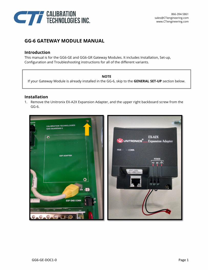
Installation 1. Remove the Unitronix EX-A2X Expansion Adapter, and the upper right backboard screw from the
GG-6.
866-394-5861 [email protected]
www.CTiengineering.com
GG6-GE-DOC1-0 Page 2
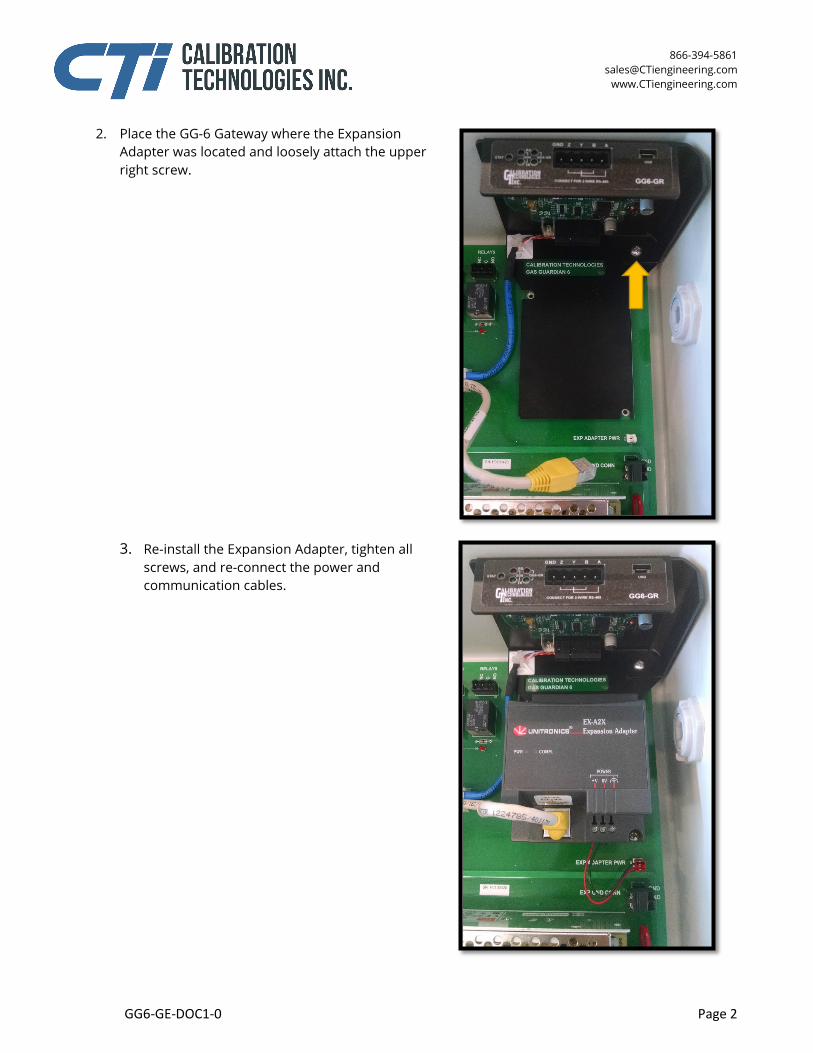
2. Place the GG-6 Gateway where the Expansion Adapter was located and loosely attach the upper right screw.
3. Re-install the Expansion Adapter, tighten all
screws, and re-connect the power and communication cables.
866-394-5861 [email protected]
www.CTiengineering.com
GG6-GE-DOC1-0 Page 3
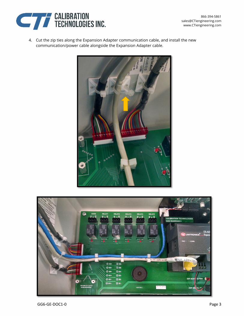
4. Cut the zip ties along the Expansion Adapter communication cable, and install the new communication/power cable alongside the Expansion Adapter cable.
866-394-5861 [email protected]
www.CTiengineering.com
GG6-GE-DOC1-0 Page 4
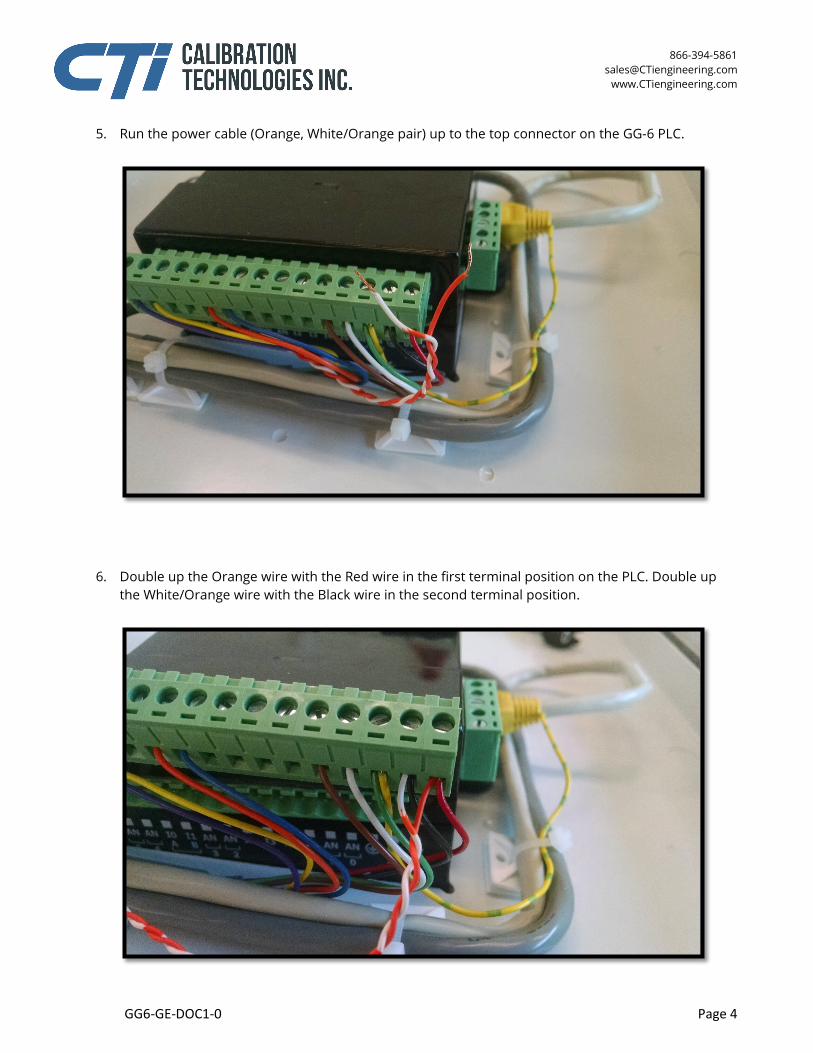
5. Run the power cable (Orange, White/Orange pair) up to the top connector on the GG-6 PLC.
6. Double up the Orange wire with the Red wire in the first terminal position on the PLC. Double up
the White/Orange wire with the Black wire in the second terminal position.
866-394-5861 [email protected]
www.CTiengineering.com
GG6-GE-DOC1-0 Page 5
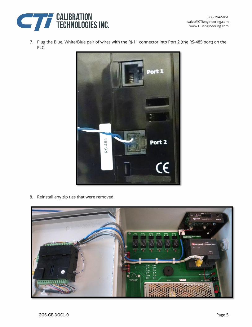
7. Plug the Blue, White/Blue pair of wires with the RJ-11 connector into Port 2 (the RS-485 port) on the PLC.
8. Reinstall any zip ties that were removed.
866-394-5861 [email protected]
www.CTiengineering.com
GG6-GE-DOC1-0 Page 6
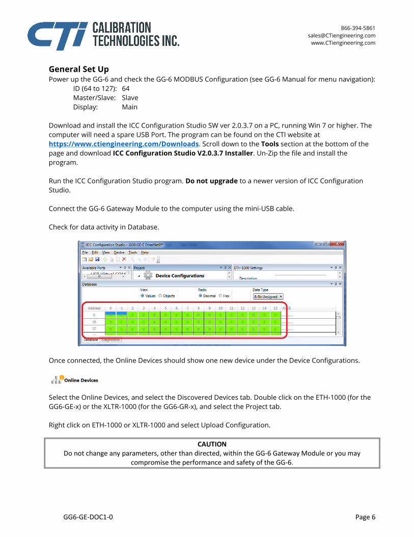
General Set Up Power up the GG-6 and check the GG-6 MODBUS Configuration (see GG-6 Manual for menu navigation): ID (64 to 127): 64 Master/Slave: Slave Display: Main Download and install the ICC Configuration Studio SW ver 2.0.3.7 on a PC, running Win 7 or higher. The computer will need a spare USB Port. The program can be found on the CTI website at https://www.ctiengineering.com/Downloads. Scroll down to the Tools section at the bottom of the page and download ICC Configuration Studio V2.0.3.7 Installer. Un-Zip the file and install the program. Run the ICC Configuration Studio program. Do not upgrade to a newer version of ICC Configuration Studio. Connect the GG-6 Gateway Module to the computer using the mini-USB cable. Check for data activity in Database.
Once connected, the Online Devices should show one new device under the Device Configurations. Select the Online Devices, and select the Discovered Devices tab. Double click on the ETH-1000 (for the GG6-GE-x) or the XLTR-1000 (for the GG6-GR-x), and select the Project tab. Right click on ETH-1000 or XLTR-1000 and select Upload Configuration.
CAUTION Do not change any parameters, other than directed, within the GG-6 Gateway Module or you may
compromise the performance and safety of the GG-6.
866-394-5861 [email protected]
www.CTiengineering.com
GG6-GE-DOC1-0 Page 7
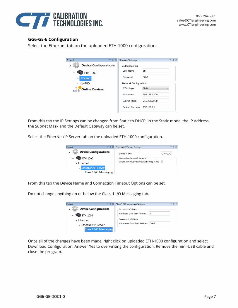
GG6-GE-E Configuration Select the Ethernet tab on the uploaded ETH-1000 configuration.
From this tab the IP Settings can be changed from Static to DHCP. In the Static mode, the IP Address, the Subnet Mask and the Default Gateway can be set. Select the EtherNet/IP Server tab on the uploaded ETH-1000 configuration.
From this tab the Device Name and Connection Timeout Options can be set. Do not change anything on or below the Class 1 I/O Messaging tab.
Once all of the changes have been made, right click on uploaded ETH-1000 configuration and select Download Configuration. Answer Yes to overwriting the configuration. Remove the mini-USB cable and close the program.
866-394-5861 [email protected]
www.CTiengineering.com
GG6-GE-DOC1-0 Page 8
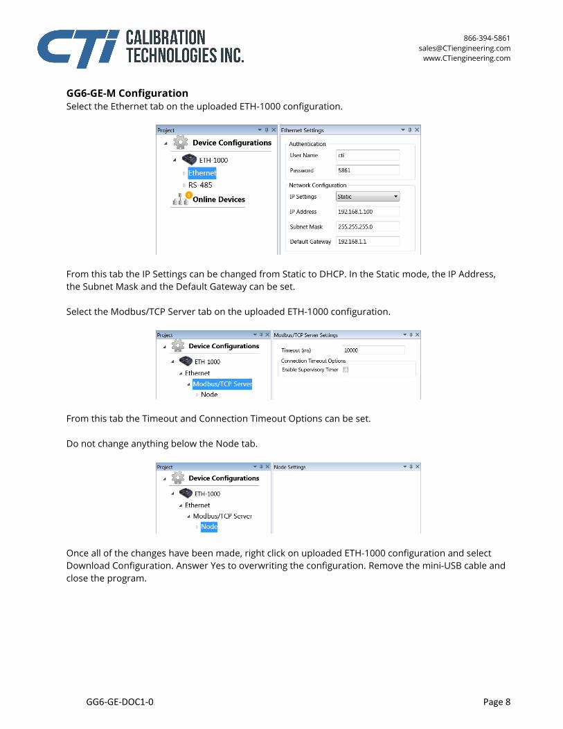
GG6-GE-M Configuration Select the Ethernet tab on the uploaded ETH-1000 configuration.
From this tab the IP Settings can be changed from Static to DHCP. In the Static mode, the IP Address, the Subnet Mask and the Default Gateway can be set. Select the Modbus/TCP Server tab on the uploaded ETH-1000 configuration.
From this tab the Timeout and Connection Timeout Options can be set. Do not change anything below the Node tab.
Once all of the changes have been made, right click on uploaded ETH-1000 configuration and select Download Configuration. Answer Yes to overwriting the configuration. Remove the mini-USB cable and close the program.
866-394-5861 [email protected]
www.CTiengineering.com
GG6-GE-DOC1-0 Page 9
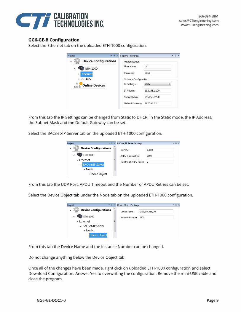
GG6-GE-B Configuration Select the Ethernet tab on the uploaded ETH-1000 configuration.
From this tab the IP Settings can be changed from Static to DHCP. In the Static mode, the IP Address, the Subnet Mask and the Default Gateway can be set. Select the BACnet/IP Server tab on the uploaded ETH-1000 configuration.
From this tab the UDP Port, APDU Timeout and the Number of APDU Retries can be set. Select the Device Object tab under the Node tab on the uploaded ETH-1000 configuration.
From this tab the Device Name and the Instance Number can be changed. Do not change anything below the Device Object tab. Once all of the changes have been made, right click on uploaded ETH-1000 configuration and select Download Configuration. Answer Yes to overwriting the configuration. Remove the mini-USB cable and close the program.
866-394-5861 [email protected]
www.CTiengineering.com
GG6-GE-DOC1-0 Page 10
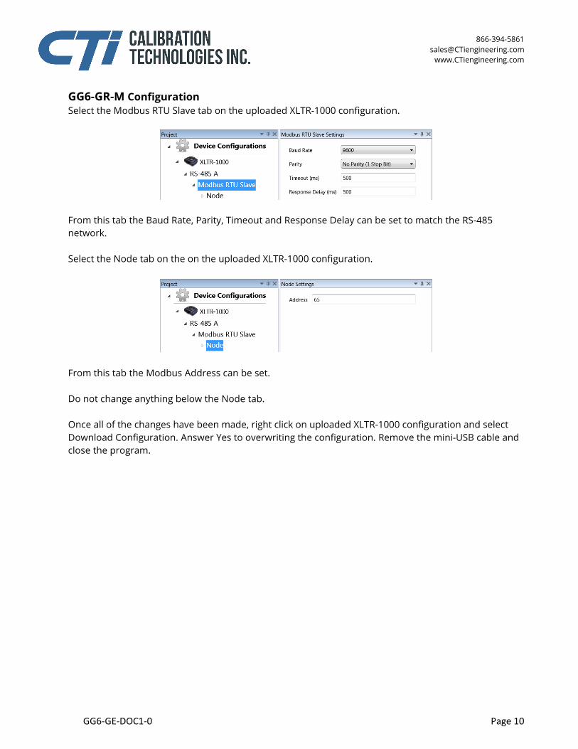
GG6-GR-M Configuration Select the Modbus RTU Slave tab on the uploaded XLTR-1000 configuration.
From this tab the Baud Rate, Parity, Timeout and Response Delay can be set to match the RS-485 network. Select the Node tab on the on the uploaded XLTR-1000 configuration.
From this tab the Modbus Address can be set. Do not change anything below the Node tab. Once all of the changes have been made, right click on uploaded XLTR-1000 configuration and select Download Configuration. Answer Yes to overwriting the configuration. Remove the mini-USB cable and close the program.
866-394-5861 [email protected]
www.CTiengineering.com
GG6-GE-DOC1-0 Page 11
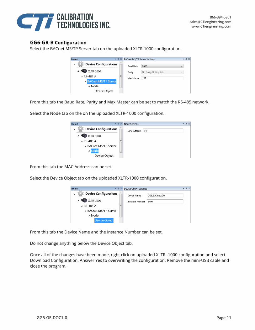
GG6-GR-B Configuration Select the BACnet MS/TP Server tab on the uploaded XLTR-1000 configuration.
From this tab the Baud Rate, Parity and Max Master can be set to match the RS-485 network. Select the Node tab on the on the uploaded XLTR-1000 configuration.
From this tab the MAC Address can be set. Select the Device Object tab on the uploaded XLTR-1000 configuration.
From this tab the Device Name and the Instance Number can be set. Do not change anything below the Device Object tab. Once all of the changes have been made, right click on uploaded XLTR -1000 configuration and select Download Configuration. Answer Yes to overwriting the configuration. Remove the mini-USB cable and close the program.
866-394-5861 [email protected]
www.CTiengineering.com
GG6-GE-DOC1-0 Page 12
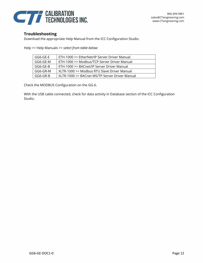
Troubleshooting Download the appropriate Help Manual from the ICC Configuration Studio. Help >> Help Manuals >> select from table below:
GG6-GE-E ETH-1000 >> EtherNet/IP Server Driver Manual GG6-GE-M ETH-1000 >> Modbus/TCP Server Driver Manual GG6-GE-B ETH-1000 >> BACnet/IP Server Driver Manual GG6-GR-M XLTR-1000 >> Modbus RTU Slave Driver Manual GG6-GR-B XLTR-1000 >> BACnet MS/TP Server Driver Manual
Check the MODBUS Configuration on the GG-6. With the USB cable connected, check for data activity in Database section of the ICC Configuration Studio.
866-394-5861 [email protected]
www.CTiengineering.com
GG6-GE-DOC1-0 Page 13
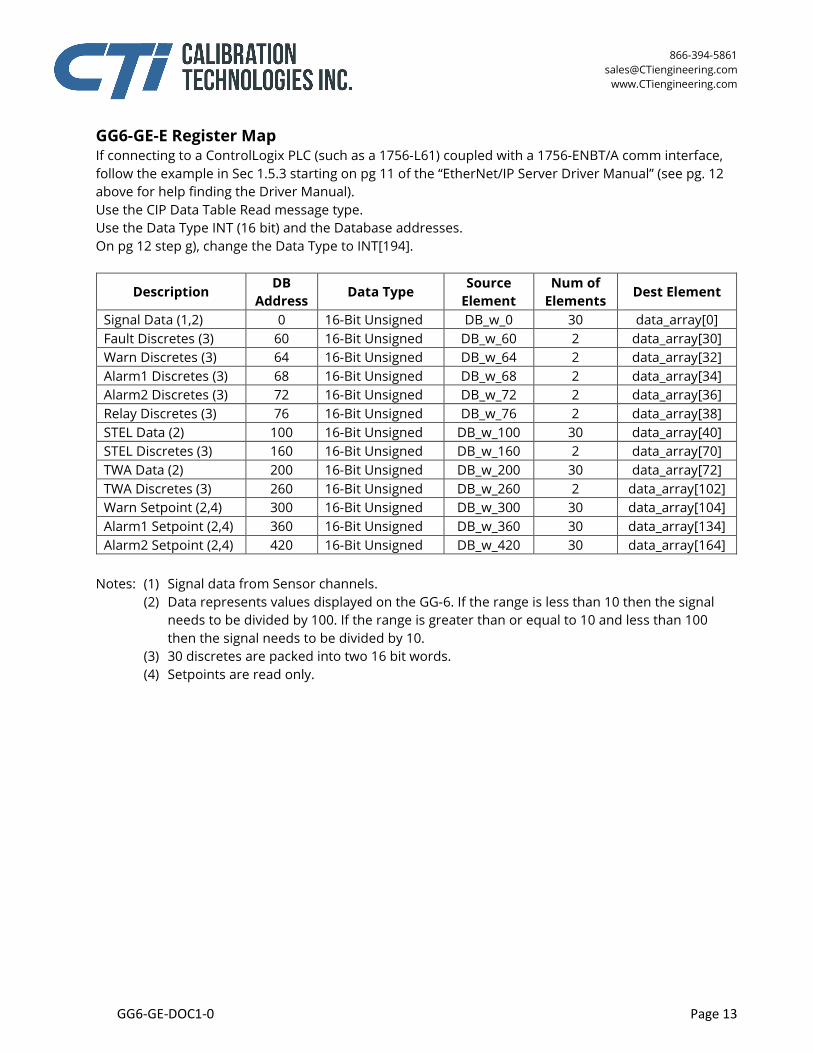
GG6-GE-E Register Map If connecting to a ControlLogix PLC (such as a 1756-L61) coupled with a 1756-ENBT/A comm interface, follow the example in Sec 1.5.3 starting on pg 11 of the “EtherNet/IP Server Driver Manual” (see pg. 12 above for help finding the Driver Manual). Use the CIP Data Table Read message type. Use the Data Type INT (16 bit) and the Database addresses. On pg 12 step g), change the Data Type to INT[194].
Description DB Address
Data Type Source Element
Num of Elements
Dest Element
Signal Data (1,2) 0 16-Bit Unsigned DB_w_0 30 data_array[0] Fault Discretes (3) 60 16-Bit Unsigned DB_w_60 2 data_array[30] Warn Discretes (3) 64 16-Bit Unsigned DB_w_64 2 data_array[32] Alarm1 Discretes (3) 68 16-Bit Unsigned DB_w_68 2 data_array[34] Alarm2 Discretes (3) 72 16-Bit Unsigned DB_w_72 2 data_array[36] Relay Discretes (3) 76 16-Bit Unsigned DB_w_76 2 data_array[38] STEL Data (2) 100 16-Bit Unsigned DB_w_100 30 data_array[40] STEL Discretes (3) 160 16-Bit Unsigned DB_w_160 2 data_array[70] TWA Data (2) 200 16-Bit Unsigned DB_w_200 30 data_array[72] TWA Discretes (3) 260 16-Bit Unsigned DB_w_260 2 data_array[102] Warn Setpoint (2,4) 300 16-Bit Unsigned DB_w_300 30 data_array[104] Alarm1 Setpoint (2,4) 360 16-Bit Unsigned DB_w_360 30 data_array[134] Alarm2 Setpoint (2,4) 420 16-Bit Unsigned DB_w_420 30 data_array[164]
Notes: (1) Signal data from Sensor channels. (2) Data represents values displayed on the GG-6. If the range is less than 10 then the signal
needs to be divided by 100. If the range is greater than or equal to 10 and less than 100 then the signal needs to be divided by 10.
(3) 30 discretes are packed into two 16 bit words. (4) Setpoints are read only.

866-394-5861 [email protected]
www.CTiengineering.com
GG6-GE-DOC1-0 Page 14
GG6-GE-M Register Map
Description Start Register
Number of Registers
Modbus Address Data Type
Signal Data (1,2,3) 30001 30 0 16-Bit Unsigned Fault Discretes (4) 30061 2 60 16-Bit Unsigned Warn Discretes (4) 30065 2 64 16-Bit Unsigned Alarm1 Discretes (4) 30069 2 68 16-Bit Unsigned Alarm2 Discretes (4) 30073 2 72 16-Bit Unsigned Relay Discretes (4) 30077 2 76 16-Bit Unsigned STEL Data (2,3) 30101 30 100 16-Bit Unsigned STEL Discretes (4) 30161 2 160 16-Bit Unsigned TWA Data (2,3) 30201 30 200 16-Bit Unsigned TWA Discretes (4) 30261 2 260 16-Bit Unsigned Warn Setpoint (2,3,5) 30301 30 300 16-Bit Unsigned Alarm1 Setpoint (2,3,5) 30361 30 360 16-Bit Unsigned Alarm2 Setpoint (2,3,5) 30421 30 420 16-Bit Unsigned
Notes: (1) Signal data from Sensor channels. (2) Two registers numbers are used to represent each data value. For example, Sensor 1 =
30001, Sensor 2 = 30003, Sensor 3 = 30005, etc. (3) Data represents values displayed on the GG-6. If the range is less than 10 then the signal
needs to be divided by 100. If the range is greater than or equal to 10 and less than 100 then the signal needs to be divided by 10.
(4) 30 discretes are packed into two 16 bit words. (5) Setpoints are read only.
866-394-5861 [email protected]
www.CTiengineering.com
GG6-GE-DOC1-0 Page 15
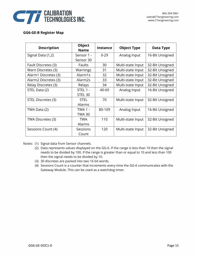
GG6-GE-B Register Map
Description Object Name Instance Object Type Data Type
Signal Data (1,2) Sensor 1 - Sensor 30
0-29 Analog Input 16-Bit Unsigned
Fault Discretes (3) Faults 30 Multi-state Input 32-Bit Unsigned Warn Discretes (3) Warnings 31 Multi-state Input 32-Bit Unsigned Alarm1 Discretes (3) Alarm1s 32 Multi-state Input 32-Bit Unsigned Alarm2 Discretes (3) Alarm2s 33 Multi-state Input 32-Bit Unsigned Relay Discretes (3) Relays 34 Multi-state Input 32-Bit Unsigned STEL Data (2) STEL 1 -
STEL 30 40-69 Analog Input 16-Bit Unsigned
STEL Discretes (3) STEL Alarms
70 Multi-state Input 32-Bit Unsigned
TWA Data (2) TWA 1 - TWA 30
80-109 Analog Input 16-Bit Unsigned
TWA Discretes (3) TWA Alarms
110 Multi-state Input 32-Bit Unsigned
Sessions Count (4) Sessions Count
120 Multi-state Input 32-Bit Unsigned
Notes: (1) Signal data from Sensor channels. (2) Data represents values displayed on the GG-6. If the range is less than 10 then the signal
needs to be divided by 100. If the range is greater than or equal to 10 and less than 100 then the signal needs to be divided by 10.
(3) 30 discretes are packed into two 16 bit words. (4) Sessions Count is a counter that increments every time the GG-6 communicates with the
Gateway Module. This can be used as a watchdog timer.
866-394-5861 [email protected]
www.CTiengineering.com
GG6-GE-DOC1-0 Page 16
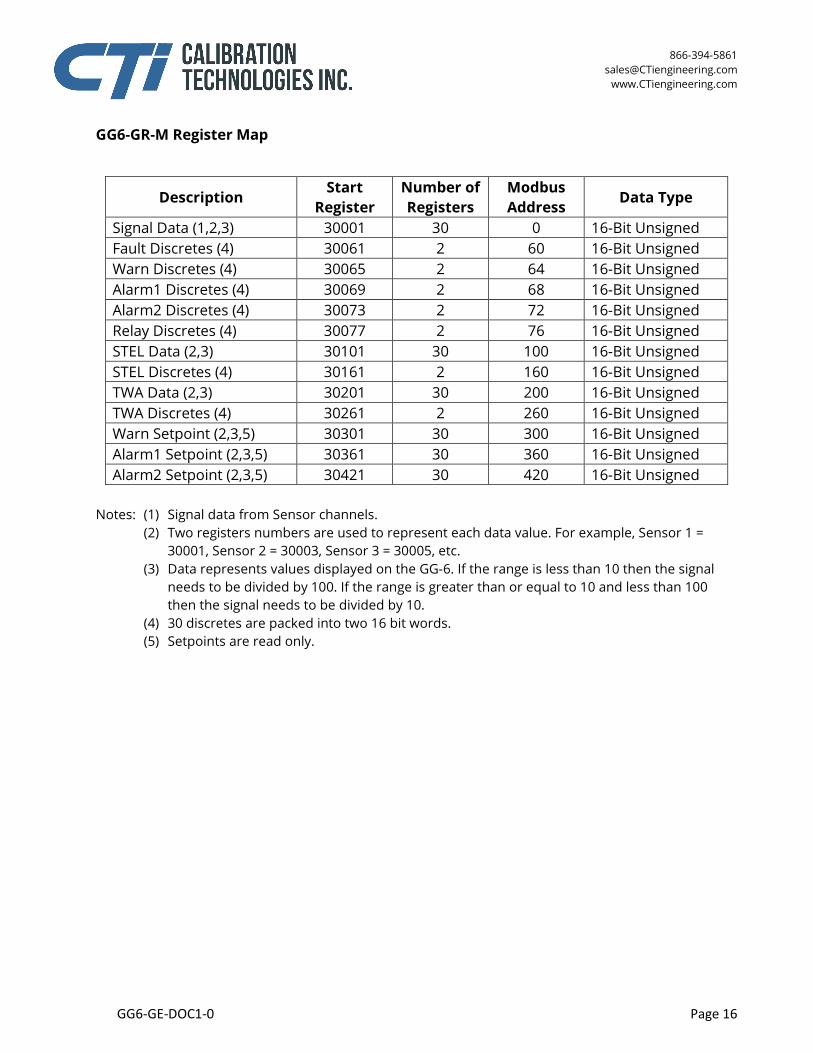
GG6-GR-M Register Map
Description Start
Register Number of Registers
Modbus Address Data Type
Signal Data (1,2,3) 30001 30 0 16-Bit Unsigned Fault Discretes (4) 30061 2 60 16-Bit Unsigned Warn Discretes (4) 30065 2 64 16-Bit Unsigned Alarm1 Discretes (4) 30069 2 68 16-Bit Unsigned Alarm2 Discretes (4) 30073 2 72 16-Bit Unsigned Relay Discretes (4) 30077 2 76 16-Bit Unsigned STEL Data (2,3) 30101 30 100 16-Bit Unsigned STEL Discretes (4) 30161 2 160 16-Bit Unsigned TWA Data (2,3) 30201 30 200 16-Bit Unsigned TWA Discretes (4) 30261 2 260 16-Bit Unsigned Warn Setpoint (2,3,5) 30301 30 300 16-Bit Unsigned Alarm1 Setpoint (2,3,5) 30361 30 360 16-Bit Unsigned Alarm2 Setpoint (2,3,5) 30421 30 420 16-Bit Unsigned
Notes: (1) Signal data from Sensor channels. (2) Two registers numbers are used to represent each data value. For example, Sensor 1 =
30001, Sensor 2 = 30003, Sensor 3 = 30005, etc. (3) Data represents values displayed on the GG-6. If the range is less than 10 then the signal
needs to be divided by 100. If the range is greater than or equal to 10 and less than 100 then the signal needs to be divided by 10.
(4) 30 discretes are packed into two 16 bit words. (5) Setpoints are read only.
866-394-5861 [email protected]
www.CTiengineering.com
GG6-GE-DOC1-0 Page 17
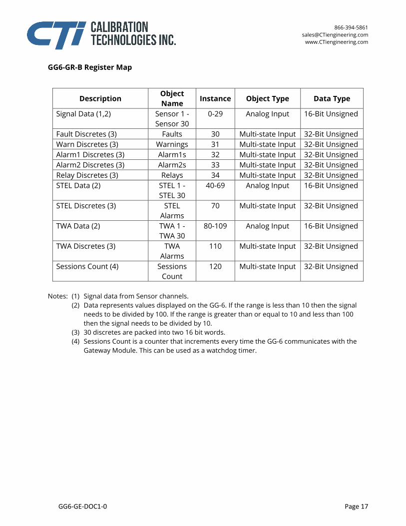
GG6-GR-B Register Map
Description Object Name Instance Object Type Data Type
Signal Data (1,2) Sensor 1 - Sensor 30
0-29 Analog Input 16-Bit Unsigned
Fault Discretes (3) Faults 30 Multi-state Input 32-Bit Unsigned Warn Discretes (3) Warnings 31 Multi-state Input 32-Bit Unsigned Alarm1 Discretes (3) Alarm1s 32 Multi-state Input 32-Bit Unsigned Alarm2 Discretes (3) Alarm2s 33 Multi-state Input 32-Bit Unsigned Relay Discretes (3) Relays 34 Multi-state Input 32-Bit Unsigned STEL Data (2) STEL 1 -
STEL 30 40-69 Analog Input 16-Bit Unsigned
STEL Discretes (3) STEL Alarms
70 Multi-state Input 32-Bit Unsigned
TWA Data (2) TWA 1 - TWA 30
80-109 Analog Input 16-Bit Unsigned
TWA Discretes (3) TWA Alarms
110 Multi-state Input 32-Bit Unsigned
Sessions Count (4) Sessions Count
120 Multi-state Input 32-Bit Unsigned
Notes: (1) Signal data from Sensor channels. (2) Data represents values displayed on the GG-6. If the range is less than 10 then the signal
needs to be divided by 100. If the range is greater than or equal to 10 and less than 100 then the signal needs to be divided by 10.
(3) 30 discretes are packed into two 16 bit words. (4) Sessions Count is a counter that increments every time the GG-6 communicates with the
Gateway Module. This can be used as a watchdog timer.


![· 2020-04-15 · ˚ ˘ [f /] -˚2 5j- 48k 5; ˝˚ p ˝k ,. ˘ gg jp ˆ ˜˝ gg / gg 4˘ ggj 5gg6 5gg ,gg 2 3 / ˆ7 gg 5gg6 ˝ gg˚ q gg :˝ ˜ ˘ ˝ w l; 6 p„ t 6 .˝- ˘ ˘ -](https://static.fdocuments.net/doc/165x107/5ea9c71468ab2b044305bbac/2020-04-15-f-2-5j-48k-5-p-k-gg-jp-oe-gg-gg.jpg)