Getting to Know autoCaD for Windows - managementboek.nl · AutoCAD ® Civil 3D®, it does focus on...
30
CHAPTER 1 Getting to Know AutoCAD for Windows Opening either the Autodesk ® AutoCAD ® or Autodesk ® AutoCAD LT ® program for the first time presents you with an expansive canvas of tools, settings, and more. Faced with this seemingly endless landscape of options, you are probably wondering where you should start. This chapter faces that question head on and breaks down the many components of the user inter- face into manageable segments, introducing you to essential operations, such as opening drawings. Even if you’ve used earlier versions of AutoCAD, you’ll still want to review this chapter to become acquainted with changes that have taken place in recent years. The 2015 release continues the evolution of the user interface seen in recent versions of the software but maintains a foundational parity between AutoCAD and AutoCAD LT. Generally speaking, both platforms offer the same 2D drafting experience. The biggest difference is that AutoCAD LT doesn’t have any 3D capability, whereas AutoCAD offers many powerful tools for 3D modeling. (These tools are the topics of Chapter 16, “Creating 3D Geometry,” and Chapter 17, “Rendering and Materials.”) With so little separating the two platforms, I refer to both interchangeably as AutoCAD for most purposes in this book. In this chapter, you will learn to ▶ ▶ Open a new drawing ▶ ▶ Familiarize yourself with the AutoCAD and AutoCAD LT Application windows ▶ ▶ Modify the display ▶ ▶ Display and arrange AutoCAD tools COPYRIGHTED MATERIAL
Transcript of Getting to Know autoCaD for Windows - managementboek.nl · AutoCAD ® Civil 3D®, it does focus on...

c01.indd 23-05-2014 09:38 AM
Chapter 1
Getting to Know autoCaD for WindowsOpening either the Autodesk® AutoCAD® or Autodesk® AutoCAD LT® program for the first time presents you with an expansive canvas of tools, settings, and more. Faced with this seemingly endless landscape of options, you are probably wondering where you should start. This chapter faces that question head on and breaks down the many components of the user inter-face into manageable segments, introducing you to essential operations, such as opening drawings. Even if you’ve used earlier versions of AutoCAD, you’ll still want to review this chapter to become acquainted with changes that have taken place in recent years.
The 2015 release continues the evolution of the user interface seen in recent versions of the software but maintains a foundational parity between AutoCAD and AutoCAD LT. Generally speaking, both platforms offer the same 2D drafting experience. The biggest difference is that AutoCAD LT doesn’t have any 3D capability, whereas AutoCAD offers many powerful tools for 3D modeling. (These tools are the topics of Chapter 16, “Creating 3D Geometry,” and Chapter 17, “Rendering and Materials.”) With so little separating the two platforms, I refer to both interchangeably as AutoCAD for most purposes in this book.
In this chapter, you will learn to
▶▶ Open a new drawing
▶▶ Familiarize yourself with the AutoCAD and AutoCAD LT Application windows
▶▶ Modify the display
▶▶ Display and arrange AutoCAD tools
COPYRIG
HTED M
ATERIAL

2 C h a p t e r 1 • G e t t i n g t o K n ow Au t o CAD f o r W i n d ow s
c01.indd 23-05-2014 09:38 AM
Starting autoCaD for WindowsIf you installed AutoCAD by using the default settings for the location of the pro-gram files, start the program by choosing Start ➢ All Programs ➢ Autodesk ➢ AutoCAD 2015 ➢ AutoCAD 2015, or by choosing Start ➢ Programs ➢ Autodesk ➢ AutoCAD LT 2015 ➢ AutoCAD LT 2015, depending on the program you’re using. (This command path might vary depending on the Windows operating system and the scheme you are using.) Alternatively, you can double-click the AutoCAD 2015 icon or the AutoCAD LT 2015 icon on your desktop.
What this Book Covers
Although this book does not focus on the discipline-specific tools found within products based on AutoCAD for Windows such as AutoCAD® Architecture or AutoCAD® Civil 3D®, it does focus on the core AutoCAD skills necessary to use these vertical AutoCAD platforms. To use one of these vertical products to learn the topics covered in this book, choose Start ➢ All Programs ➢ Autodesk ➢ AutoCAD Product Name 2015 ➢ AutoCAD Product Name As AutoCAD 2015.
The Mac version of AutoCAD applies an OS X native interface that differs from its Windows counterparts. Although the core concepts covered in this book are universal, the step-by-step procedures differ between the two operating systems. The procedures covered in this book are intended for use with only the Windows-based version of AutoCAD.
exploring the User Interface Like most Windows-based applications, AutoCAD launches inside an Application window. Serving as a starting point, the New Tab is the first user interface (UI) displayed within the Application window, but workspaces will control the overall composition of your AutoCAD environment from there. I’ll explain the general function of workspaces shortly, including the default workspace named Drafting & Annotation, but first I’ll explain the New Tab.

E x p l o r i n g t h e U s e r I n t e r f a c e 3
c01.indd 23-05-2014 09:38 AM
Using the New tabBefore creating or opening any drawings, the New Tab is displayed to provide a starting point for your entire AutoCAD experience. This interface is organized into two parts: one page for creating drawings, and another page for learning about AutoCAD. The Create page shown in Figure 1.1 is displayed by default and serves as a launchpad for creating and working with the drawing files that com-pose your projects.
F I G U r e 1 . 1 : The Create page on the New Tab
The Create page contains three columns and may include up to four panels:
Get Started Serving as a pseudo File menu, the Get Started panel is focused on creating new files and browsing for existing files. The Start Drawing tool enables you to quickly create new drawing files, whereas the other tools let you open existing drawings and sheet sets, access templates online, and even view a collection of sample drawings.
recent Documents AutoCAD keeps a running record of each drawing file you open and displays the most recent drawings in this panel. The length of this recent document history is configurable with the OPTIONS command.

4 C h a p t e r 1 • G e t t i n g t o K n ow Au t o CAD f o r W i n d ow s
c01.indd 23-05-2014 09:38 AM
Notifications This panel is visible only when there is an issue regarding your current configuration of AutoCAD. It notifies you of graphic configuration issues, product updates, and more.
Connect Autodesk® 360 is the cloud computing platform integrated into AutoCAD 2015. The Connect panel is made up of cloud services such as storage and rendering, and it provides quick access to the full portfolio of Autodesk 360 services.
Selecting the Learn page tab at the bottom of the New Tab, or the page arrow on the left edge, opens the Learn page shown in Figure 1.2. You can access basic information about AutoCAD from this page.
F I G U r e 1 . 2 : The Learn page on the New Tab
Like the Create page, the Learn page is divided into three columns and includes panels for the following:
What’s New This panel features video content demonstrating the many new features and enhancements found in AutoCAD 2015.
Getting Started Videos The videos on this panel are intended for anyone just getting started with AutoCAD, and highlight a collection of tools essential for creating drawings.
tip This panel is especially helpful after you master the basics of AutoCAD. It displays suggestions for streamlining your existing workflows.

E x p l o r i n g t h e U s e r I n t e r f a c e 5
c01.indd 23-05-2014 09:38 AM
Online resources Quickly access web-based materials such as the main AutoCAD Services & Support page, which provides access to product informa-tion, troubleshooting articles, and even training videos.
Introducing WorkspacesOur tour of the user interface has so far been limited to the New Tab that dis-plays after starting AutoCAD. Opening or creating a drawing will dismiss the New Tab interface and load a vast assortment of tools in addition to the drawing you selected. To load this interface, click the Start Drawing tool on the Create page.
The collection of tools displayed after creating or opening a drawing is called a workspace, and AutoCAD includes several designed to match the type of work you’re doing. Most of this book uses the default Drafting & Annotation work-space, but Chapters 16 and 17 (which focus on 3D) use the available 3D work-spaces. The standard workspaces found within AutoCAD are as follows:
Drafting & annotation Utilizing the Ribbon, this workspace (shown in Figure 1.3) is considered the default AutoCAD workspace. Unless otherwise specified, this is also the workspace used throughout this book.
Application MenuQuick Access Toolbar
Ribbon TabTitle Bar
Ribbon PanelInfoCenter
Ribbon
ViewCube
Navigation Bar
Drawing Area
Status Bar
Command Line
Layout Tabs
UCS Icon
Cursor
In-Canvas Viewport Control
File Tabs
F I G U r e 1 . 3 : The Drafting & Annotation workspace
◀
AutoCAD and AutoCAD LT offer numerous dia-log boxes with various combinations of buttons and text boxes. You’ll learn many of their functions as you prog-ress through the book.
6 C h a p t e r 1 • G e t t i n g t o K n ow Au t o CAD f o r W i n d ow s
c01.indd 23-05-2014 09:38 AM
3D Basics Provides the core tools needed to get started with 3D modeling in AutoCAD (for AutoCAD users only—3D features are not included in AutoCAD LT).
3D Modeling Provides the complete set of 3D modeling tools found in AutoCAD, including materials via the Materials Browser (for AutoCAD users only—3D features are not included in AutoCAD LT).
AutoCAD verticals such as AutoCAD Architecture and AutoCAD Civil 3D build on the standard workspaces outlined here and introduce discipline-specific tools in tandem with those found in the standard version of AutoCAD discussed in this book. Although any AutoCAD vertical can be used to complete the exercises in this book, I recommend using the AutoCAD vertical (for example, Architecture or Civil 3D) as an AutoCAD application shortcut to start AutoCAD and maintain parity with this book.
exploring the Drafting & annotation WorkspaceAs the default UI configuration for AutoCAD, the Drafting & Annotation work-space shown previously in Figure 1.3 serves as the primary workspace through-out this book. Having a good understanding of this workspace is imperative as you perform the exercises in the coming chapters. To ensure your success with those exercises, I’ll start by breaking down what you can expect when using the Drafting & Annotation workspace. From top to bottom and from left to right, the following elements make up this workspace:
application Menu The Application menu contains the tools for opening, sav-ing, and printing (plotting) your drawings. These options are similar to the File drop-down menu that has been deprecated since the Ribbon was introduced in AutoCAD. When the Application menu is open, the menus for these tools project from the upper-left corner of the AutoCAD window and cover the drawing area and any open dialog boxes.
Quick access toolbar Located to the right of the Application menu, the Quick Access toolbar provides immediate access to some of the most frequently used commands to complete tasks such as creating, opening, saving, and plot-ting drawings. This toolbar is a customizable element of the UI that maintains a consistent appearance as you interact with your designs, and many AutoCAD users choose to build on its default task coverage.

E x p l o r i n g t h e U s e r I n t e r f a c e 7
c01.indd 23-05-2014 09:38 AM
title Bar The title bar is analogous to the title bar in any Windows program. It contains the program name (AutoCAD or AutoCAD LT) and the title of the current drawing with its path, provided a drawing other than the default Drawing#.dwg is open.
the ribbon Located immediately below the title bar, and spanning the entire width of the Application window, the Ribbon serves as the primary launchpad for nearly every command used to compose drawings in AutoCAD. Related tasks are found under the different tabs, which are further segmented into panels containing similar tools. The “Using the Ribbon” section later in this chapter explains this taxonomy in greater detail.
InfoCenter To the far right of the title bar is the InfoCenter, containing the Search, Autodesk 360, Autodesk Exchange Apps, and Help buttons. You can enter a question in the field to the left of the Search button to access informa-tion from a number of locations quickly, including the standard AutoCAD help system through the drop-down panel. The Autodesk 360 button allows you to sign in with your Autodesk ID and access a wealth of cloud-based services that integrate with AutoCAD. The Help button is a direct link to the AutoCAD help system (also accessible by pressing the F1 key).
File tabs A tab for each open drawing is displayed at the top of the drawing area. These tabs provide a visual method to quickly switch between open draw-ings or to create new drawings. Should you prefer additional screen real estate in lieu of this functionality, File Tabs can be turned off from the Interface panel of the View Ribbon tab.
Drawing area and Cursor The blank middle section of the screen is called the drawing area. This represents a virtually infinite plane. The crosshairs, or cursor as it’s known in AutoCAD, allows you to navigate the drawing area to precisely compose your designs.
ViewCube ® Found in the upper-right corner of the drawing area, the ViewCube is primarily used for navigating three-dimensional drawings. It pro-vides access to 26 predefined view orientations in addition to the basic ability to pivot a drawing.
In-Canvas Viewport Control Displayed in the upper-left corner of the draw-ing area, the In-Canvas Viewport Controls provide a quick, and convenient way to change the current view, visual style, or viewport configuration.

8 C h a p t e r 1 • G e t t i n g t o K n ow Au t o CAD f o r W i n d ow s
c01.indd 23-05-2014 09:38 AM
Navigation Bar Beneath the ViewCube, you’ll find the Navigation bar, which pro-vides access to several universal and product-specific navigation tools. These tools, while tailored to the specific commands found in AutoCAD, are designed to mimic navigation features found in other Autodesk products such as Autodesk® Revit®.
UCS Icon The User Coordinate System (UCS) is discussed in Chapter 2, “Learning Basic Commands to Get Started.” The UCS icon, an essential part of this system, is found in the lower-left corner of the drawing area and indicates the positive coordinates for the x-, y-, and z-axes.
Command Line Serving as the primary method for interacting with AutoCAD, the command-line interface is located by default along the bottom edge of the drawing area. Similar to a paper-tape roll on a printing calculator, the command-line interface displays a history of previous actions as well as a summary of the current actions for which the system seeks your input.
Layout tabs Each AutoCAD drawing consists of a model tab and any number of layout tabs whose name can be customized. As a general rule, the model tab represents your design, and the layout tabs represent the piece of paper used to document a design. The Layout Tab interface allows you to quickly switch between these views of your design.
Status Bar The status bar, streamlined in AutoCAD 2015, is now aligned to the bottom-right corner of the Application window. Tools located on the status bar are primarily focused on helping you draw and on managing the user interface. You’ll probably find yourself using the status bar quite frequently, so I’ll describe each of its tools in a moment.
N O t e The illustrations in this book show the drawing area of the AutoCAD user interface with a white background. However, the default and preferred UI is a dark gray or black background, used to reduce eyestrain. The color choice in the book is simply for readability.
If your screen does not look like Figure 1.3, you need to make a few changes:
1. Click the Workspace Switching tool from the status bar, and choose Drafting & Annotation, as shown in Figure 1.4. Alternatively, command-line users can launch the WSCURRENT command by entering the following:
WSCURRENT↵drafting & annotation↵

E x p l o r i n g t h e U s e r I n t e r f a c e 9
c01.indd 23-05-2014 09:38 AM
F I G U r e 1 . 4 : Selecting the Drafting & Annotation workspace
The drawing area in the center of the screen is an infinite canvas where you’ll create your designs; however, it might need to be adjusted.
2. Using the View Controls tool on the in-canvas Viewport controls, select the Top option (see Figure 1.5).
F I G U r e 1 . 5 : Selecting the Top option by using the in-canvas Viewport controls
This step ensures that your view is perpendicular to the drawing area. It should be as though you were looking straight down at a piece of paper on a drawing table.

1 0 C h a p t e r 1 • G e t t i n g t o K n ow Au t o CAD f o r W i n d ow s
c01.indd 23-05-2014 09:38 AM
3. From the in-canvas Viewport controls, click the Visual Style control to display a list of visual styles. Select the 2D Wireframe option from the list, as shown in Figure 1.6.
F I G U r e 1 . 6 : Selecting the 2D Wireframe visual style by using in-canvas Viewport controls
Your screen should now look similar to Figure 1.3 shown previously.
putting the User Interface to WorkEvery pixel of the user interface serves a specific purpose, but what exactly is that purpose? So far you’ve learned about the general composition of the AutoCAD UI, gaining a basic understanding about each of its components. During that initial exploration, you likely noticed that many interface elements such as the Ribbon and status bar introduce another level of granularity with the tools they contain.
Although subsequent chapters provide detailed instruction for using these tools, it’s important that you possess a solid understanding of interface orga-nization, function, and fundamental purpose. Some of these mission-critical UI elements include the Ribbon, the File Tab interface, the command line, the Application menu, and the status bar. By mastering the uses of these interface elements, you will possess the skills necessary to complete the design and docu-mentation exercises throughout this book.

P u t t i n g t h e U s e r I n t e r f a c e t o Wo r k 1 1
c01.indd 23-05-2014 09:38 AM
Choosing Your Own Drawing area Background Color
By default, AutoCAD uses a dark gray color for the drawing area. Some users prefer to customize this and several other UI elements to a color palette of their liking. For example, some users prefer the contrast ratio of a light background color such as yellow or white over the contrast ratio offered by the darker background color. Follow these steps to change the drawing area’s background color:
1. Open the Options dialog box by typing OP↵ at the command line, or choose Application menu ➢ Options.
2. Switch to the Display tab and click the Colors button in the Window Elements group.
This opens the Drawing Window Colors dialog box, where you’ll customize the colors of the user interface to your liking.
3. In the Drawing Window Colors dialog box, select 2D Model Space from the Context list and select Uniform Background from the Interface Element list, as shown in the following graphic.

1 2 C h a p t e r 1 • G e t t i n g t o K n ow Au t o CAD f o r W i n d ow s
c01.indd 23-05-2014 09:38 AM
Using the ribbonPerhaps one of the most prominent elements of the AutoCAD interface is the Ribbon (see Figure 1.7). By default, it extends across the top of the AutoCAD window, but it can be repositioned. Depending on the size of your AutoCAD win-dow (or current screen resolution), the Ribbon may look a little different on your computer. That’s because the Ribbon self-adjusts according to the size of the AutoCAD window. To see the Ribbon in its fully expanded state, you must have a screen resolution wider than 1350 pixels. When the width is too narrow to display each panel fully, AutoCAD begins to collapse the panels, replacing each with a single button bearing the panel name.
Ribbon Tabs
Large Tool Icon (Button) Small Tool Icon (Button)Panel
Collapsed Ribbon Panel
F I G U r e 1 . 7 : The Ribbon fully displaying all panels (top) and with partially and completely collapsed panels (bottom)
The Ribbon is divided into three parts—tabs, panels, and tools:
ribbon tabs Ribbon tabs offer the highest level of organization; they group Ribbon panels by task. For instance, commands related to plotting (printing) are found on the Output tab, whereas commands related to entering text can be found on the Annotate tab.

P u t t i n g t h e U s e r I n t e r f a c e t o Wo r k 1 3
c01.indd 23-05-2014 09:38 AM
ribbon panels Similar tools are grouped together into a series of Ribbon panels. For instance, the Move, Erase, and Rotate tools modify objects. Consequently, each of these tools is found on the Modify panel.
ribbon tools The individual icons and various drop-down lists found on the Ribbon are known as Ribbon tools. Clicking any of these tools launches the command associated with it.
When more tools are available than will fit on a panel, an arrow is displayed on the panel’s title bar. Clicking the title bar expands the panel and exposes the additional tools. Follow these steps to learn how the Ribbon tools work and how they display information:
1. Click the Home tab on the Ribbon to expose the Home tab’s panels (see the top of Figure 1.7 shown earlier).
2. Move your cursor over the Modify panel, and pause the cursor over the Move tool button.
This exposes the button’s tooltip, as shown in Figure 1.8. In addition to displaying the name of the tool, the tooltip provides a brief descrip-tion of its function, the command-line equivalent of clicking the tool, and instructions to press the F1 key to open the AutoCAD Help file to the current tool’s Help page.
F I G U r e 1 . 8 : The tooltip for the Move command

1 4 C h a p t e r 1 • G e t t i n g t o K n ow Au t o CAD f o r W i n d ow s
c01.indd 23-05-2014 09:38 AM
3. After a few seconds of hovering over the Move tool button, the tooltip is replaced with a cue card, as shown in Figure 1.9. Cue cards show the step-by-step implementation of the tool.
F I G U r e 1 . 9 : The cue card for the Move tool
4. Click the Modify panel’s title bar to expand the panel and expose all of the Modify tools (see Figure 1.10).
F I G U r e 1 . 1 0 : The expanded Modify panel
5. Often you may find yourself returning to the same tool on an expanded Ribbon panel. When that happens, you can pin the panel open by clicking the pushpin-shaped button in the bottom-left cor-ner. When the panel is pinned open, it remains open even when the cursor is not hovering over it.

P u t t i n g t h e U s e r I n t e r f a c e t o Wo r k 1 5
c01.indd 23-05-2014 09:38 AM
6. Click the button again to unpin the panel, and then move the cursor off the panel to collapse it. Regardless of whether a panel is pinned or unpinned, it will automatically collapse if you change Ribbon tabs.
7. Click the Modify panel title and drag the cursor toward the drawing area.The Modify panel becomes semitransparent, allowing you to place
it inside the drawing area to become a floating panel (see Figure 1.11). Floating panels display whether their host tab is current or not. This feature can be helpful when quick access to tools on separate Ribbon tabs is needed simultaneously.
F I G U r e 1 . 1 1 : Drag the Modify panel from the Ribbon (top) to display it a floating panel (bottom).
8. To return the Modify panel to the Ribbon, hover over its title and then click the Return Panels To Ribbon button shown in Figure 1.12.
Return Panels ToRibbon Button
F I G U r e 1 . 1 2 : Using the Return Panels To Ribbon button to restore a floating panel to its host Ribbon tab
Using File tabs to Manage DrawingsAs in many programs, you can have multiple drawings open in the same session of AutoCAD. When multiple drawings are open, each drawing window is stacked behind the drawings in front of it. The File Tab feature helps streamline the management of these drawings by adding a tab for each drawing just below the

1 6 C h a p t e r 1 • G e t t i n g t o K n ow Au t o CAD f o r W i n d ow s
c01.indd 23-05-2014 09:38 AM
Ribbon. This interface not only provides a fast and visual way to switch between open drawings, but also offers several other file management functions for opening, saving, and even creating new drawings. To use File Tabs:
1. Start or open two or more AutoCAD files. Right-clicking any draw-ing tab or the plus icon at the end of the interface, as shown in Figure 1.13, will allow you to open additional files.
F I G U r e 1 . 1 3 : Using the File Tab interface to open additional drawings
2. Click any tab to bring the corresponding drawing to the front of the AutoCAD window.
3. Pausing your cursor over any tab will display the thumbnail preview of the associated drawing and its contents (see Figure 1.14). Click the thumbnail to navigate directly to that portion of the drawing file.
F I G U r e 1 . 1 4 : Using the File Tab interface to display a thumbnail preview of a drawing’s content
4. You can toggle the display of the File Tab interface by clicking the File Tabs icon on the User Interface panel of the View Ribbon tab. You’ll be using the File Tab interface throughout this book, so I rec-ommend keeping it on for the time being.

P u t t i n g t h e U s e r I n t e r f a c e t o Wo r k 1 7
c01.indd 23-05-2014 09:38 AM
Working in the Command-Line InterfaceThe command-line interface, which is docked by default along the bottom edge of the drawing area, serves as your primary method of interacting with AutoCAD. You use this interface to tell the software what you would like it to do for you, and the software uses this interface to communicate the information it needs from you. If you’re just getting started with AutoCAD, this interaction may feel a little abstract at first. A golden rule of using AutoCAD is that when you’re in doubt about what you need to do, or what the program is expecting you to do, look at the command line.
Depending on your individual preference, you may choose to display this interface in either docked or undocked mode, as shown in Figure 1.15. The default undocked mode helps maximize the available drawing area and enables you to position the command line anywhere onscreen. By contrast, you may choose to dock the command line to the top or bottom of the AutoCAD interface. Doing this will lock the command-line interface to the AutoCAD Application window, shrinking the available drawing area.
F I G U r e 1 . 1 5 : The command-line interface in its default undocked mode (top), and docked to the bottom of the Application window (bottom)
Similar to a paper-tape roll on a printing calculator, the command-line interface, or command prompt as it’s known within AutoCAD, displays a history of previous actions as well as a summary of the current calculation. Just as you can choose when to tear the paper tape on a printing calculator, you can choose the number of previous command-line entries to display. In its default undocked state, the command-line interface displays three lines of prompt history, and it can display as many as 50 lines at any one time. To customize the range of prompt history:
1. Click the wrench icon to the left of the command-line interface.
2. Choose Lines Of Prompt History from the contextual menu, as shown in Figure 1.16. The command line reads CLIPROMPTLINES Enter new value for CLIPROMPTLINES <3>:, as shown in Figure 1.17.

1 8 C h a p t e r 1 • G e t t i n g t o K n ow Au t o CAD f o r W i n d ow s
c01.indd 23-05-2014 09:38 AM
F I G U r e 1 . 1 6 : Choosing Lines Of Prompt History from the undocked command-line interface
F I G U r e 1 . 1 7 : Specifying the range of prompt history from the command-line interface
3. Enter the desired number of prompt history lines to display, up to 50, and press ↵.
When in Doubt, Keep Calm and Look at the Command Line
Interacting with AutoCAD is much like chatting with a friend who has a topical response for every statement you make. Every time you ask or say something in AutoCAD, it will respond via the command-line interface.
The command line will play a critical role in nearly every task you perform in AutoCAD. One especially challenging aspect of AutoCAD is learning its often abstract and unique vocabulary. The synonym suggestion feature makes this challenge a little more manageable by proposing an appropriate AutoCAD term from a more common term. For example, if I asked you to insert a symbol for a wall receptacle, your intuition might tell you to try the SYMBOL command (see Figure 1.18). Although there is no such command, AutoCAD 2015 automatically suggests the correct command: INSERT.

P u t t i n g t h e U s e r I n t e r f a c e t o Wo r k 1 9
c01.indd 23-05-2014 09:38 AM
F I G U r e 1 . 1 8 : Entering SYMBOL at the command line elicits the correct INSERT command.
Should you choose to type commands at the command line, there’s a good chance you’ll discover many new commands, thanks to the autocomplete fea-ture. While it’s a good way to learn the names of new commands, that won’t help much if you have no idea what they do or how to use them. Two icons to the right of the command name guide you to a wealth of information about it. To use these icons:
1. Enter LINE at the command line and notice the list of possible com-mands the autocomplete feature displays, as shown in Figure 1.19. As you might expect, in addition to the LINE command, several other command names containing line are displayed.
F I G U r e 1 . 1 9 : List of autocomplete options for the LINE command
2. Clicking the question mark icon will search the AutoCAD help docu-mentation, whereas clicking the globe icon will search the Internet. Click the globe icon for the LINETYPE command, and the Google search page displays, as shown in Figure 1.20.

2 0 C h a p t e r 1 • G e t t i n g t o K n ow Au t o CAD f o r W i n d ow s
c01.indd 23-05-2014 09:38 AM
F I G U r e 1 . 2 0 : Google search performed by clicking the globe autocomplete icon for the LINETYPE command
N O t e You can start AutoCAD commands in a number of ways: from the Ribbon, the Application menu, the command line, and the menus that appear when you right-click. When you get used to drawing with AutoCAD, you’ll learn some shortcuts to start commands, and you’ll find the method that best suits the way you work.
Understanding the Status BarThe status bar is located below the command line (see Figure 1.21), and docked in the lower-right corner of the Application window.
F I G U r e 1 . 2 1 : The default status bar configuration
By default, the status bar includes 18 buttons, but it can be customized to include as many as 21. These buttons perform a variety of functions, which include activat-ing various drawing modes, navigating and controlling objects in the drawing area,

P u t t i n g t h e U s e r I n t e r f a c e t o Wo r k 2 1
c01.indd 23-05-2014 09:38 AM
and managing the user interface. You’ll have the chance to explore each of the draw-ing modes and aids throughout this book. As a preview, the following list briefly describes each of the tools shown by default:
N O t e The tooltip displayed while hovering over each status bar tool usually varies from the tool’s actual name. The following list indicates the tooltip you’ll see, fol-lowed by the name of each tool in parentheses.
Display Drawing Grid (Grid Display) Mimics a piece of graph paper by dis-playing nonplotting horizontal and vertical lines in the drawing’s background.
Snap Mode (Snap Mode) Restricts movement of the cursor inside the drawing area to specified intervals.
restrict Cursor Orthogonally (Ortho Mode) Restricts movement of the cursor to 90º intervals: 0 ,̊ 90 ,̊ 180 ,̊ and 270˚ by default.
Isometric Drawing (Isometric Drafting) Aligns the cursor to sketch 3D representations of objects on a 2D plane using one of three isometric planes: top, left, or right.
Show Snapping reference Lines (Object Snap tracking) An advanced draft-ing tool that allows you to draw objects with specific geometric relationships to other objects within your drawing. This tool is discussed in Chapter 5, “Developing Drawing Strategies: Part 2.”
Snap Cursor to 2D reference points (Object Snap) Helps you draw objects based on geometric reference points such as endpoint, midpoint, intersection, and so on. Mastering the use of object snaps is critical in the creation of accu-rate drawings.
Show annotation Objects (annotation Visibility) Controls the display of annotative objects, by providing an advanced method for managing text, dimensions, and other objects used to tell the story of your designs. This tool is discussed in Chapter 8, “Controlling Text in a Drawing.”
add Scales to annotative Objects when the annotation Scale Changes (autoScale) Aids in quickly configuring annotative objects such as text and dimensions to display at multiple scales (discussed in Chapter 8).
annotation Scale of the Current View (annotation Scale) Controls the dis-played size of scale-dependent objects such as annotative text and dimensions, and linetypes in a drawing.

2 2 C h a p t e r 1 • G e t t i n g t o K n ow Au t o CAD f o r W i n d ow s
c01.indd 23-05-2014 09:38 AM
Workspace Switching (Workspace Switching) Manages the composition of the user interface by providing access to workspace management and custom-ization tools.
annotation Monitor (annotation Monitor) When enabled, the associativity of annotations is monitored, and a system tray alert is displayed when annota-tions become disassociated.
hardware acceleration (Graphics performance) Helps improve 3D graphics performance for compatible graphics cards supporting OpenGL.
autodesk trustedDWG (autodesk trustedDWG) This icon will display only after opening a DWG™ file, and indicates whether a drawing was created with Autodesk software (trusted) or a third-party application (untrusted).
Isolate Objects (Isolate Objects) Temporarily makes objects within a drawing invisible, isolating only the items you select. As a temporary visibility override, previously hidden objects are always displayed when a drawing is opened.
Clean Screen (Clean Screen) Hides most interface elements such as the Ribbon, and maximizes the drawing area to focus on the current drawing.
Customization (Customization) Opens a menu used to manage which status bar tools are visible. The menu reference for each tool is listed in parentheses in this list.
Using the application MenuThe Application menu contains the tools for opening, saving, and printing (plotting) your drawings, similar to the options found under the File drop-down menu in AutoCAD and many other programs. When the Application menu is open, the menus for these tools project from the upper-left corner of the AutoCAD window and cover the drawing area and any open dialog boxes.
Perform the following steps to begin using the Application menu:
1. Click the Application Menu button to open the Application menu.
2. The left pane of the Application menu displays the various com-mands. Clicking or hovering over a command displays its options in the right pane, as shown in Figure 1.22.
▶
Be careful not to double-click the Application Menu button, because doing so will make AutoCAD close.

P u t t i n g t h e U s e r I n t e r f a c e t o Wo r k 2 3
c01.indd 23-05-2014 09:38 AM
F I G U r e 1 . 2 2 : The Application menu showing the Print options
A bar with an up- or down-arrow at the top or bottom of the right pane indicates that additional tools are available. You can display these tools by placing your cursor over either bar.
The Application menu offers a quick method for opening drawings. You can even see a thumbnail preview of the drawings and arrange drawings that you frequently edit so that they are easily accessible. Here’s how:
1. To open a new AutoCAD file from the Application menu, choose New ➢ Drawing, as shown in Figure 1.23.
F I G U r e 1 . 2 3 : Opening a new drawing from the Application menu

2 4 C h a p t e r 1 • G e t t i n g t o K n ow Au t o CAD f o r W i n d ow s
c01.indd 23-05-2014 09:38 AM
This opens the Select Template dialog box, where you select a tem-plate on which to base the new drawing. Opening a file with a template is covered in Chapter 2. Close the Select Template dialog box to return to the Application Window.
2. To open an existing file from the Application menu, choose Open ➢ Drawing, as shown in Figure 1.24.
F I G U r e 1 . 2 4 : Opening an existing drawing from the Application menu
This opens the Select File dialog box, where you can navigate to the desired drawing file and select it. Close the Select File dialog box to return to the Application Window.
3. To open a file that you’ve worked on recently, click the Recent Documents button at the top of the Application menu’s left pane. This displays the most recent files opened in AutoCAD in the right pane, as shown in Figure 1.25.
F I G U r e 1 . 2 5 : Displaying the recent documents in the Application menu

P u t t i n g t h e U s e r I n t e r f a c e t o Wo r k 2 5
c01.indd 23-05-2014 09:38 AM
4. Hover over a filename in the right pane to display a thumbnail pre-view of the drawing and additional information, including the draw-ing location and AutoCAD drawing format (see Figure 1.26).
F I G U r e 1 . 2 6 : Displaying a thumbnail of the selected file
Opening New Files
You can open new or existing files by using the New or Open button in the Quick Access toolbar. Existing drawings can also be opened by dragging them from a Windows Explorer window to the AutoCAD title bar.

2 6 C h a p t e r 1 • G e t t i n g t o K n ow Au t o CAD f o r W i n d ow s
c01.indd 23-05-2014 09:38 AM
N O t e AutoCAD 2015 uses the AutoCAD 2013 drawing (DWG) file format. This means that the files created in AutoCAD 2015 are compatible only with AutoCAD 2013, AutoCAD 2014, and AutoCAD 2015. You can share drawings with releases earlier than AutoCAD 2013 by performing a simple conversion. To convert a 2013 format drawing to a prior version, open the Application menu and then click Save As ➢ Drawing and choose the version you want from the Files Of Type drop-down list at the bottom of the Save Drawing As dialog box.

U s i n g t h e K e y b o a r d 2 7
c01.indd 23-05-2014 09:38 AM
Getting the Most Out of the recent Documents List
The Application menu offers many time-saving tips. Here are two of the best ways to use the Recent Documents list:
access Frequently Used Drawings For drawings you access on a regular basis and would like to remain on the Recent Documents list, click the pushpin that displays next to its name. This will “pin” that drawing to the Recent Documents list until you unpin it.
Maximize the Number of recent Documents By default, the Recent Documents list displays only the last nine drawings you’ve opened. This number can be increased to 50 by using the OPTIONS command, selecting the Open And Save tab, and changing the Number Of Recently Used Files setting under the Application Menu group.
The next chapter will familiarize you with a few basic commands that will enable you to draw a small diagram. If you want to take a break and close AutoCAD, choose Application menu ➢ Exit AutoCAD (lower-right corner), and choose not to save the drawing.
Using the KeyboardThe keyboard is an important tool for entering data and commands. If you’re a good typist, you can gain speed in working with AutoCAD by learning how to enter commands from the keyboard. AutoCAD provides alias commands—single keys or key combinations that start any of several frequently used commands. A good example of a command alias that ships with AutoCAD is the LINE command. You

2 8 C h a p t e r 1 • G e t t i n g t o K n ow Au t o CAD f o r W i n d ow s
c01.indd 23-05-2014 09:38 AM
could type LINE at the command line to launch the command, but typing the one-character alias L is much quicker and easier. You can add more aliases or change the existing ones as you become more familiar with the program.
In addition to the alias commands, you can use several of the F keys (function keys) on the top row of the keyboard as two-way or three-way toggles to turn AutoCAD functions on and off. Although buttons on the screen duplicate these functions (Snap, Grid, and so on), it’s sometimes faster to use the F keys.
While working in AutoCAD, you’ll need to enter a lot of data (such as dimen-sions and construction notes), answer questions with Yes or No, and use the arrow keys. You’ll use the keyboard constantly. It might help to get into the habit of keeping your left hand on the keyboard and your right hand on the mouse if you’re right-handed, or the other way around if you’re left-handed.
Using the MouseYour mouse most likely has two buttons and a scroll wheel. So far in this chap-ter, you have used the left mouse button to choose menus, commands, and options, and you’ve held it down to drag the Ribbon. The left mouse button is the one you’ll be using most often, but you’ll also use the right mouse button.
While drawing, you’ll use the right mouse button for the following three operations:
▶▶ To display a menu containing options relevant to the particular step you’re in at the moment
▶▶ To use in combination with the Shift or Ctrl key to display a menu containing special drawing aids called object snaps
▶▶ To display a menu of toolbars when the pointer is on any icon of a toolbar that is currently open
The middle button with a scroll wheel serves a dual function:
▶▶ Pressing and holding the middle button enables you to pan through-out your drawing until you release the middle button.
▶▶ You can zoom in and out within your drawing. When scrolling toward the screen, you zoom into your drawing. Conversely, when scrolling away from the screen, you zoom out from your drawing.
I f Yo u Wou l d L i k e Mo r e P r a c t i c e… 2 9
c01.indd 23-05-2014 09:38 AM
AutoCAD makes extensive use of toolbars and the right-click menu feature. This makes your mouse an important input tool. The keyboard is necessary for inputting numeric data and text, and it has hot keys and aliases that can speed up your work; however, the mouse is the primary tool for selecting options and controlling toolbars.
If You Would Like More practice…At the start of this chapter, you learned how workspaces can dramatically change the overall appearance of AutoCAD. This was illustrated in the “Exploring the User Interface” section, as you switched between workspaces that ship with the software. Although many find the default workspaces more than adequate, others prefer custom-tailoring the UI to the way they work.
From customizing the Ribbon to loading toolbars and beyond, AutoCAD provides a large collection of tools to personalize its layout. Regardless of the extent of your customization efforts, that configuration will be lost unless it’s first saved as a workspace.
Follow these steps to ensure your customizations remain the next time you start AutoCAD:
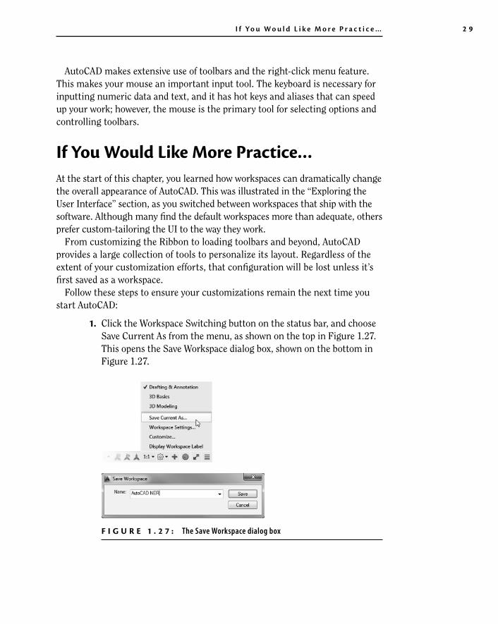
1. Click the Workspace Switching button on the status bar, and choose Save Current As from the menu, as shown on the top in Figure 1.27. This opens the Save Workspace dialog box, shown on the bottom in Figure 1.27.
F I G U r e 1 . 2 7 : The Save Workspace dialog box

3 0 C h a p t e r 1 • G e t t i n g t o K n ow Au t o CAD f o r W i n d ow s
c01.indd 23-05-2014 09:38 AM
2. Type AutoCAD NER as the name for the workspace and click Save. The dialog box closes, and you are returned to your workspace.
Until you change it or select a different workspace, the AutoCAD NER workspace setup will remain as it is now.
When you make changes to a workspace by adding a toolbar or changing the background color of the drawing area, you can easily update the current work-space to accommodate those changes. Follow steps 1 and 2, naming the work-space again with the same name. You’ll get a warning window telling you that a workspace by that name already exists and asking whether you want the new arrangement to replace the old one. Click Yes.
are You experienced?Now you can…
✔✔ recognize the elements of the AutoCAD Application window
✔✔ understandhowthecommand-lineinterfaceworksandwhyitisimportant
✔✔ startcommandsfromtheRibbon
✔✔ start commands from the command line
✔✔ switchbetweenopendrawings
✔✔ use the Application menu
✔✔ saveaworkspaceofyourscreensetupinAutoCAD