Geographic information Spatial referencing by...
118
“Hak Cipta Badan Standardisasi Nasional, Copy standar ini dibuat untuk penayangan di website dan tidak untuk di komersialkan” SNI ISO 19111:2011 Standar Nasional Indonesia Informasi geografis — Pereferensian spasial dengan koordinat Geographic information — Spatial referencing by coordinates (ISO 19111:2007, IDT) ICS 35.240.70 Badan Standardisasi Nasional
-
Upload
nguyennguyet -
Category
Documents
-
view
215 -
download
0
Transcript of Geographic information Spatial referencing by...

“Hak C
ipta Badan S
tandardisasi Nasional, C
opy standar ini dibuat untuk penayangan di website dan tidak untuk di kom
ersialkan”
SNI ISO 19111:2011
Standar Nasional Indonesia
Informasi geografis — Pereferensian spasial dengan
koordinat
Geographic information — Spatial referencing by coordinates
(ISO 19111:2007, IDT)
ICS 35.240.70
Badan Standardisasi Nasional

“Hak C
ipta Badan S
tandardisasi Nasional, C
opy standar ini dibuat untuk penayangan di website dan tidak untuk di kom
ersialkan”
© BSN 2011 Hak cipta dilindungi undang-undang. Dilarang menyalin atau menggandakan sebagian atau seluruh isi dokumen ini dengan cara dan dalam bentuk apapun dan dilarang mendistribusikan dokumen ini baik secara elektronik maupun tercetak tanpa izin tertulis dari BSN BSN Gd. Manggala Wanabakti Blok IV, Lt. 3,4,7,10. Telp. +6221-5747043 Fax. +6221-5747045 Email: [email protected] www.bsn.go.id Diterbitkan di Jakarta
“Hak C
ipta Badan S
tandardisasi Nasional, C
opy standar ini dibuat untuk penayangan di website dan tidak untuk di kom
ersialkan”
SNI ISO 19111:2011
i
Contents 1 Scope .............................................................................................................................. 1
2 Conformance requirements ............................................................................................. 1
3 Normative references ...................................................................................................... 1
4 Terms and definitions ...................................................................................................... 2
5 Conventions .................................................................................................................... 7
5.1 Symbols ........................................................................................................................... 7
5.2 Abbreviated terms ........................................................................................................... 8
5.3 UML notation ................................................................................................................... 9
5.4 Attribute status .............................................................................................................. 10
6 Spatial referencing by coordinates — Overview ............................................................ 10
6.1 Relationship between coordinates and coordinate reference system ........................... 10
6.2 UML model for spatial referencing by coordinates — Overview .................................... 12
7 Identified Object package .............................................................................................. 13
7.1 General .......................................................................................................................... 13
7.2 UML schema for the Identified Object package ............................................................. 14
8 Coordinate Reference System package ........................................................................ 16
8.1 Reference system.......................................................................................................... 16
8.2 Coordinate reference system ........................................................................................ 16
8.3 UML schema for the Coordinate Reference System package ...................................... 18
9 Coordinate System package ......................................................................................... 27
9.1 Introduction .................................................................................................................... 27
9.2 Coordinate system ........................................................................................................ 27
9.3 Coordinate system axis ................................................................................................. 28
9.4 UML schema for the Coordinate System package ........................................................ 29
10 Datum package ............................................................................................................. 45
10.1 Types of datums ............................................................................................................ 45
10.2 Geodetic datum ............................................................................................................. 45
10.3 UML schema for the Datum package ............................................................................ 45
11 Coordinate Operation package...................................................................................... 55
11.1 General characteristics of coordinate operations .......................................................... 55
11.2 UML schema for the Coordinate Operation package .................................................... 55
Annex A (normative) Abstract test suite ................................................................................ 51
Annex B (informative) Context for modelling of spatial referencing by coordinates .............. 72
Annex C (informative) Spatial referencing by coordinates – Geodetic concepts ................... 82
© BSN 2011

“Hak C
ipta Badan S
tandardisasi Nasional, C
opy standar ini dibuat untuk penayangan di website dan tidak untuk di kom
ersialkan”
SNI ISO 19111:2011
ii
Annex D (informative) Examples ........................................................................................... 65
Annex E (informative) Recommended best practice for interfacing to ISO 19111 ................ 77
Bibliography .......................................................................................................................... 109
© BSN 2011

“Hak C
ipta Badan S
tandardisasi Nasional, C
opy standar ini dibuat untuk penayangan di website dan tidak untuk di kom
ersialkan”
SNI ISO 19111:2011
iii
Prakata Standar ini merupakan hasil adopsi identik standar ISO 19111:2007(E), Geographic information — Spatial referencing by coordinates. Standar ini dibuat dengan menggunakan metode cetak ulang sesuai dengan acuan dan ketentuan yang berlaku dari Badan Standardisasi Nasional (BSN). Standar ini dirumuskan oleh Panitia Teknis 07-01, Informasi Geografi/Geomatika, melalui proses perumusan standar dan terakhir dibahas dalam rapat konsensus tanggal 24 November 2010 di Cibinong, yang dihadiri oleh perwakilan dari pemerintah, produsen, konsumen, pakar, dan institusi terkait lainnya. Standar ini disusun berdasarkan ketentuan yang tercantum dalam:
a) Pedoman Standardisasi Nasional (PSN) 03.1:2007, Adopsi Standar Internasional dan Publikasi Internasional lainnya Bagian 1: Adopsi Standar Internasional menjadi SNI (ISO/IEC Guide 21-1:2005, Regional or national adoption of International Standards and other International Deliverables – Part 1: Adoption of International Standards, MOD);
b) PSN 08:2007, Penulisan Standar Nasional Indonesia.
© BSN 2011

“Hak C
ipta Badan S
tandardisasi Nasional, C
opy standar ini dibuat untuk penayangan di website dan tidak untuk di kom
ersialkan”
SNI ISO 19111:2011
iv
Introduction Geographic information contains spatial references which relate the features represented in the data to positions in the real world. Spatial references fall into two categories: — those using coordinates; — those based on geographic identifiers. Spatial referencing by geographic identifiers is defined in ISO 19112 [4]. This National Standard describes the data elements, relationships and associated metadata required for spatial referencing by coordinates. It describes the elements that are necessary to fully define various types of coordinate systems and coordinate reference systems applicable to geographic information. The subset of elements required is partially dependent upon the type of coordinates. This National Standard also includes optional fields to allow for the inclusion of non-essential coordinate reference system information. The elements are intended to be both machine and human readable. The traditional separation of horizontal and vertical position has resulted in coordinate reference systems that are horizontal (2D) and vertical (1D) in nature, as opposed to truly three-dimensional. It is established practice to define a three-dimensional position by combining the horizontal coordinates of a point with a height or depth from a different coordinate reference system. In this National Standard, this concept is defined as a compound coordinate reference system. The concept of coordinates can be expanded from a strictly spatial context to include time. ISO 19108 describes temporal schema. Time can be added as a temporal coordinate reference system within a compound coordinate reference system. It is even possible to add two time-coordinates, provided the two coordinates describe different independent quantities. EXAMPLE An example is the time/space position of a subsurface point of which the vertical coordinate is expressed as the two-way travel time of a sound signal in milliseconds, as is common in seismic imaging. A second time-coordinate indicates the time of observation, usually expressed in whole years. Certain scientific communities use three-dimensional systems where horizontal position is combined with a non-spatial parameter. In these communities, the parameter is considered to be a third, vertical axis. The parameter, although varying monotonically with elevation or depth, does not necessarily vary in a simple manner; thus, conversion from the parameter to height or depth is non-trivial. The parameters concerned are normally absolute measurements and the datum is taken with reference to a direct physical measurement of the parameter. These non-spatial parameters are beyond the scope of this National Standard. However, the modelling constructs described within this National Standard can be applied through a profile specific to a community. In addition to describing a coordinate reference system, this National Standard provides for the description of a coordinate transformation or a coordinate conversion between two different coordinate reference systems. With such information, spatial data referred to different coordinate reference systems can be related to one specified coordinate reference system. This facilitates spatial data integration. Alternatively, an audit trail of coordinate reference system manipulations can be maintained.
© BSN 2011

“Hak C
ipta Badan S
tandardisasi Nasional, C
opy standar ini dibuat untuk penayangan di website dan tidak untuk di kom
ersialkan”
SNI ISO 19111:2011
1 dari 109
Geographic information — Spatial referencing by coordinates 1 Scope This National Standard defines the conceptual schema for the description of spatial referencing by coordinates, optionally extended to spatio-temporal referencing. It describes the minimum data required to define one-, two- and three-dimensional spatial coordinate reference systems with an extension to merged spatial-temporal reference systems. It allows additional descriptive information to be provided. It also describes the information required to change coordinates from one coordinate reference system to another. In this National Standard, a coordinate reference system does not change with time. For coordinate reference systems defined on moving platforms such as cars, ships, aircraft and spacecraft, the transformation to an Earth-fixed coordinate reference system can include a time element. This National Standard is applicable to producers and users of geographic information. Although it is applicable to digital geographic data, its principles can be extended to many other forms of geographic data such as maps, charts and text documents. The schema described can be applied to the combination of horizontal position with a third non-spatial parameter which varies monotonically with height or depth. This extension to non-spatial data is beyond the scope of this National Standard but can be implemented through profiles. 2 Conformance requirements This National Standard defines two classes of conformance, Class A for conformance of coordinate reference systems and Class B for coordinate operations between two coordinate reference systems. Any coordinate reference system claiming conformance to this National Standard shall satisfy the requirements given in A.1. Any coordinate operation claiming conformance to this National Standard shall satisfy the requirements given in A.2. 3 Normative references The following referenced documents are indispensable for the application of this document. For dated references, only the cited edition applies. For undated references, the latest edition of the referenced document (including any amendments) applies. ISO/TS 19103, Geographic information — Conceptual schema language ISO 19108, Geographic information — Temporal schema ISO 19115, Geographic information — Metadata Normative reference to ISO 19115 is restricted as follows. In this National Standard, normative reference to ISO 19115 excludes the MD_CRS class and its component classes. ISO 19115 class MD_CRS and its component classes specify descriptions of coordinate reference systems elements. These elements are modelled in this National Standard. NOTE The MD_CRS class and its component classes were deleted from ISO 19115:2003 through
© BSN 2011

“Hak C
ipta Badan S
tandardisasi Nasional, C
opy standar ini dibuat untuk penayangan di website dan tidak untuk di kom
ersialkan”
SNI ISO 19111:2011
2 dari 109
Technical Corrigendum 1:2006. 4 Terms and definitions For the purposes of this document, the following terms and definitions apply. 4.1 affine coordinate system coordinate system in Euclidean space with straight axes that are not necessarily mutually perpendicular 4.2 Cartesian coordinate system coordinate system which gives the position of points relative to n mutually perpendicular axes NOTE n is 2 or 3 for the purposes of this National Standard. 4.3 compound coordinate reference system coordinate reference system using at least two independent coordinate reference systems NOTE Coordinate reference systems are independent of each other if coordinate values in one cannot be converted or transformed into coordinate values in the other. 4.4 concatenated operation coordinate operation consisting of sequential application of multiple coordinate operations 4.5 coordinate one of a sequence of n numbers designating the position of a point in n-dimensional space NOTE In a coordinate reference system, the coordinate numbers are qualified by units. 4.6 coordinate conversion coordinate operation in which both coordinate reference systems are based on the same datum EXAMPLE Conversion from an ellipsoidal coordinate reference system based on the WGS 84 datum to a Cartesian coordinate reference system also based on the WGS 84 datum, or change of units such as from radians to degrees or feet to meters. NOTE A coordinate conversion uses parameters which have specified values that are not determined empirically. 4.7 coordinate operation change of coordinates, based on a one-to-one relationship, from one coordinate reference system to another NOTE Super type of coordinate transformation and coordinate conversion.
© BSN 2011

“Hak C
ipta Badan S
tandardisasi Nasional, C
opy standar ini dibuat untuk penayangan di website dan tidak untuk di kom
ersialkan”
SNI ISO 19111:2011
3 dari 109
4.8 coordinate reference system coordinate system that is related to an object by a datum NOTE For geodetic and vertical datums, the object will be the Earth. 4.9 coordinate set collection of coordinate tuples related to the same coordinate reference system 4.10 coordinate system set of mathematical rules for specifying how coordinates are to be assigned to points 4.11 coordinate transformation coordinate operation in which the two coordinate reference systems are based on different datums NOTE A coordinate transformation uses parameters which are derived empirically by a set of points with known coordinates in both coordinate reference systems. 4.12 coordinate tuple tuple composed of a sequence of coordinates NOTE The number of coordinates in the coordinate tuple equals the dimension of the coordinate system; the order of coordinates in the coordinate tuple is identical to the order of the axes of the coordinate system. 4.13 cylindrical coordinate system three-dimensional coordinate system with two distance and one angular coordinates 4.14 datum parameter or set of parameters that define the position of the origin, the scale, and the orientation of a coordinate system 4.15 depth distance of a point from a chosen reference surface measured downward along a line perpendicular to that surface NOTE A depth above the reference surface will have a negative value. 4.16 easting E distance in a coordinate system, eastwards (positive) or westwards (negative) from a north-south reference line 4.17 ellipsoid surface formed by the rotation of an ellipse about a main axis
© BSN 2011

“Hak C
ipta Badan S
tandardisasi Nasional, C
opy standar ini dibuat untuk penayangan di website dan tidak untuk di kom
ersialkan”
SNI ISO 19111:2011
4 dari 109
NOTE In this National Standard, ellipsoids are always oblate, meaning that the axis of rotation is always the minor axis. 4.18 ellipsoidal coordinate system geodetic coordinate system coordinate system in which position is specified by geodetic latitude, geodetic longitude and (in the threedimensional case) ellipsoidal height 4.19 ellipsoidal height geodetic height h distance of a point from the ellipsoid measured along the perpendicular from the ellipsoid to this point, positive if upwards or outside of the ellipsoid NOTE Only used as part of a three-dimensional ellipsoidal coordinate system and never on its own. 4.20 engineering coordinate reference system coordinate reference system based on an engineering datum EXAMPLES Local engineering and architectural grids; coordinate reference system local to a ship or an orbiting spacecraft. 4.21 engineering datum local datum datum describing the relationship of a coordinate system to a local reference NOTE Engineering datum excludes both geodetic and vertical datums. EXAMPLE A system for identifying relative positions within a few kilometres of the reference point. 4.22 flattening f ratio of the difference between the semi-major (a) and semi-minor axis (b) of an ellipsoid to the semi-major axis; f (a – b)/a NOTE Sometimes inverse flattening 1/f a/(a – b) is given instead; 1/f is also known as reciprocal flattening. 4.23 geodetic coordinate reference system coordinate reference system based on a geodetic datum 4.24 geodetic datum datum describing the relationship of a two- or three-dimensional coordinate system to the Earth 4.25 geodetic latitude ellipsoidal latitude φ
© BSN 2011

“Hak C
ipta Badan S
tandardisasi Nasional, C
opy standar ini dibuat untuk penayangan di website dan tidak untuk di kom
ersialkan”
SNI ISO 19111:2011
5 dari 109
angle from the equatorial plane to the perpendicular to the ellipsoid through a given point, northwards treated as positive 4.26 geodetic longitude ellipsoidal longitude λ angle from the prime meridian plane to the meridian plane of a given point, eastward treated as positive 4.27 geoid equipotential surface of the Earth’s gravity field which is everywhere perpendicular to the direction of gravity and which best fits mean sea level either locally or globally 4.28 gravity-related height H height dependent on the Earth’s gravity field NOTE This refers to in particular orthometric height or normal height, which are both approximations of the distance of a point above the mean sea level. 4.29 height h, H distance of a point from a chosen reference surface measured upward along a line perpendicular to that surface NOTE A height below the reference surface will have a negative value. 4.30 image coordinate reference system coordinate reference system based on an image datum 4.31 image datum engineering datum which defines the relationship of a coordinate system to an image 4.32 linear coordinate system one-dimensional coordinate system in which a linear feature forms the axis EXAMPLES Distances along a pipeline; depths down a deviated oil well bore. 4.33 map projection coordinate conversion from an ellipsoidal coordinate system to a plane 4.34 mean sea level average level of the surface of the sea over all stages of tide and seasonal variations NOTE Mean sea level in a local context normally means mean sea level for the region calculated from observations at one or more points over a given period of time. Mean sea level in a global
© BSN 2011

“Hak C
ipta Badan S
tandardisasi Nasional, C
opy standar ini dibuat untuk penayangan di website dan tidak untuk di kom
ersialkan”
SNI ISO 19111:2011
6 dari 109
context differs from a global geoid by not more than 2 m. 4.35 meridian intersection of an ellipsoid by a plane containing the shortest axis of the ellipsoid NOTE This term is often used for the pole-to-pole arc rather than the complete closed figure. 4.36 northing N distance in a coordinate system, northwards (positive) or southwards (negative) from an east-west reference line 4.37 polar coordinate system two-dimensional coordinate system in which position is specified by distance and direction from the origin NOTE For the three-dimensional case, see spherical coordinate system (4.44). 4.38 prime meridian zero meridian meridian from which the longitudes of other meridians are quantified 4.39 projected coordinate reference system coordinate reference system derived from a two-dimensional geodetic coordinate reference system by applying a map projection 4.40 semi-major axis a semi-diameter of the longest axis of an ellipsoid NOTE This equates to the semi-diameter of the ellipsoid measured in its equatorial plane. 4.41 semi-minor axis b semi-diameter of the shortest axis of an ellipsoid NOTE The shortest axis coincides with the rotation axis of the ellipsoid and therefore contains both poles. 4.42 sequence finite, ordered collection of related items (objects or values) that may be repeated [ISO 19107] 4.43 spatial reference description of position in the real world
© BSN 2011

“Hak C
ipta Badan S
tandardisasi Nasional, C
opy standar ini dibuat untuk penayangan di website dan tidak untuk di kom
ersialkan”
SNI ISO 19111:2011
7 dari 109
NOTE This may take the form of a label, code or coordinate tuple. 4.44 spherical coordinate system three-dimensional coordinate system with one distance measured from the origin and two angular coordinates, commonly associated with a geodetic coordinate reference system NOTE Not to be confused with an ellipsoidal coordinate system based on an ellipsoid ‘degenerated’ into a sphere. 4.45 tuple ordered list of values [ISO 19136] 4.46 unit defined quantity in which dimensioned parameters are expressed NOTE In this National Standard, the subtypes of units are length units, angular units, time units, scale units and pixel spacing units. 4.47 vertical coordinate reference system one-dimensional coordinate reference system based on a vertical datum 4.48 vertical coordinate system one-dimensional coordinate system used for gravity-related height or depth measurements 4.49 vertical datum datum describing the relation of gravity-related heights or depths to the Earth NOTE In most cases, the vertical datum will be related to mean sea level. Ellipsoidal heights are treated as related to a three-dimensional ellipsoidal coordinate system referenced to a geodetic datum. Vertical datums include sounding datums (used for hydrographic purposes), in which case the heights may be negative heights or depths. 5 Conventions 5.1 Symbols a semi-major axis b semi-minor axis E easting f flattening H gravity-related height
© BSN 2011

“Hak C
ipta Badan S
tandardisasi Nasional, C
opy standar ini dibuat untuk penayangan di website dan tidak untuk di kom
ersialkan”
SNI ISO 19111:2011
8 dari 109
h ellipsoidal height N northing λ geodetic longitude φ geodetic latitude E, N Cartesian coordinates in a projected coordinate reference system X, Y, Z Cartesian coordinates in a geodetic coordinate reference system i, j, [k] Cartesian coordinates in an engineering coordinate reference system r, θ polar coordinates in a 2D engineering coordinate reference system r, Ω, θ spherical coordinates in a 3D engineering or geodetic coordinate reference system 5.2 Abbreviated terms CC change coordinates (package abbreviation in UML model) CD coordinate datum (package abbreviation in UML model) CCRS compound coordinate reference system CRS coordinate reference system CS coordinate system (also, package abbreviation in UML model) IO identified object (package abbreviation in UML model) MSL mean sea level pixel a contraction of “picture element”, the smallest element of a digital image to
which attributes are assigned RS reference system (package abbreviation in UML model) SC spatial referencing by coordinates (package abbreviation in UML model) SI le Système International d’unités UML Unified Modeling Language URI Uniform Resource Identifier 1D one-dimensional 2D two-dimensional 3D three-dimensional
© BSN 2011

“Hak C
ipta Badan S
tandardisasi Nasional, C
opy standar ini dibuat untuk penayangan di website dan tidak untuk di kom
ersialkan”
SNI ISO 19111:2011
9 dari 109
5.3 UML notation In this National Standard, the conceptual schema for describing coordinate reference systems and coordinate operations is modelled with the Unified Modelling Language (UML). The basic data types and UML diagram notations are defined in ISO/TS 19103 and ISO/IEC 19501 [9]. In this National Standard, the following stereotypes of UML classes are used: a) <<DataType>> a descriptor of a set of values that lack identity (independent existence
and the possibility of side effects); a DataType is a class with no operations whose primary purpose is to hold the information;
b) <<Type>> a class used for specification of a domain of objects together with
operations applicable to the objects; c) <<CodeList>> a flexible enumeration that uses string values for expressing a list of
potential values; d) <<Union>> contains a list of attributes where only one of those attributes can be
present at any time. The following data types defined in ISO/TS 19103 are used: Angle amount of rotation required to bring one line or plane into coincidence
with another; Boolean a value specifying TRUE or FALSE; CharacterString a sequence of characters; Date a character string which comprises year, month and day in the format as
specified by ISO 8601; GenericName a generic name structure in the context of namespaces, defined in
ISO/TS 19103; Integer an integer number; Length the measure of distance; Measure result from performing the act or process of ascertaining the extent,
dimensions or quantity of some entity; Number abstract class that can be subtyped to a specific number type (real,
integer, decimal, double, float); Scale the ratio of one quantity to another; Unit of Measure any of the systems devised to measure some physical quantity. In addition, a Sequence type of collection is used, which contains an ordered list of values with the specified data type. The format used is “Sequence<DataType>”. In the UML diagrams in this National Standard, grey boxes indicate classes from other packages.
© BSN 2011

“Hak C
ipta Badan S
tandardisasi Nasional, C
opy standar ini dibuat untuk penayangan di website dan tidak untuk di kom
ersialkan”
SNI ISO 19111:2011
10 dari 109
5.4 Attribute status In this National Standard, attributes are given an obligation status:
Obligation Definition Meaning
M mandatory This attribute shall be supplied.
C conditional This attribute shall be supplied if the condition (given in the attribute description) is true. It may be supplied if the condition is false.
O optional This attribute may be supplied.
In this National Standard, the Maximum Occurrence column indicates the maximum number of occurrences of attribute values that are permissible, with N indicating no upper limit. 6 Spatial referencing by coordinates — Overview 6.1 Relationship between coordinates and coordinate reference system In this National Standard, a coordinate is one of n scalar values that define the position of a single point. In other contexts, the term ordinate is used for a single value and coordinate for multiple ordinates. Such usage is not part of this National Standard. A coordinate tuple is an ordered list of n coordinates that define the position of a single point. In this National Standard, the coordinate tuple shall be composed of one, two or three spatial coordinates. The coordinates shall be mutually independent and their number shall be equal to the dimension of the coordinate space. EXAMPLE A coordinate tuple cannot contain two heights. Coordinates are ambiguous until the system to which those coordinates are related has been fully defined. Without the full specification of the system, coordinates are ambiguous at best and meaningless at worst. A coordinate reference system (CRS) defines the coordinate space such that the coordinate values are unambiguous. In this National Standard, the order of the coordinates within the coordinate tuple and their unit(s) of measure shall be parts of the coordinate reference system definition. In this National Standard, a coordinate set shall be a collection of coordinate tuples referenced to the same coordinate reference system. A CRS identification or definition in accordance with this National Standard shall be associated with every coordinate tuple. If only one point is being described, the association shall be direct. For a coordinate set, one CRS identification or definition may be associated with the coordinate set and then all coordinate tuples in that coordinate set inherit that association. The conceptual relationship of coordinate tuple and coordinate set to coordinate reference system is shown in Figure 1.
© BSN 2011

“Hak C
ipta Badan S
tandardisasi Nasional, C
opy standar ini dibuat untuk penayangan di website dan tidak untuk di kom
ersialkan”
SNI ISO 19111:2011
11 dari 109
Figure 1 — Conceptual relationship of coordinates to coordinate reference system The semantic meaning of coordinate tuple and coordinate set is reflected in the modelling of classes DirectPosition and GM_Object respectively; this modelling is in ISO 19107 [3]. In this National Standard, a coordinate reference system shall be comprised of one coordinate system and one datum (see Figure 2).
Figure 2 — Conceptual model of a coordinate reference system The high level abstract model for spatial referencing by coordinates is shown in Figure 3. A coordinate transformation or coordinate conversion operates on coordinates, not on coordinate reference systems. Coordinate operation has been modelled in ISO 19107 [3] by the operation “Transform” of the GM_Object class.
© BSN 2011

“Hak C
ipta Badan S
tandardisasi Nasional, C
opy standar ini dibuat untuk penayangan di website dan tidak untuk di kom
ersialkan”
SNI ISO 19111:2011
12 dari 109
Figure 3 — Conceptual model for spatial referencing by coordinates NOTE A coordinate operation may be single or concatenated. Refer to Clause 11. The description of quality of a spatial reference is covered by the provisions of ISO 19115. 6.2 UML model for spatial referencing by coordinates — Overview The specification for spatial referencing by coordinates is defined in this National Standard in the form of a UML model with supplementary text. The UML model contains five primary UML packages, as shown in Figure 4. Each box represents a package, and contains the package name. Each arrowed line shows the dependency (at the head of the arrow) of one package upon another package.
Figure 4 — UML model packages and dependencies The five UML packages for spatial referencing by coordinates are more completely specified in the Clauses 7 through 11. Further context for the requirements of Clauses 7 through 11 is given in Annex B and some geodetic concepts underpinning spatial referencing by coordinates are given in Annex C. Examples illustrating how this National Standard can be applied when defining a coordinate reference system or a coordinate operation are given in Annex D. Recommendations for referencing to classes defined in this National Standard are given in Annex E.
© BSN 2011

“Hak C
ipta Badan S
tandardisasi Nasional, C
opy standar ini dibuat untuk penayangan di website dan tidak untuk di kom
ersialkan”
SNI ISO 19111:2011
13 dari 109
7 Identified Object package 7.1 General The Identified Object package contains attributes common to several objects used in spatial referencing by coordinates. These objects – including datum, ellipsoid, coordinate system axis and coordinate operation – inherit attribute values from the Identified Object package. One of the attributes is the object primary name. This may have alternative names or aliases. EXAMPLE 1A datum name might be “North American Datum of 1983” and its abbreviation “NAD83”. Object primary names have a data type RS_Identifier which is defined in ISO 19115 whilst aliases have a data type GenericName which is defined in ISO/TS 19103. Another attribute is identifier. This is a unique code used to reference an object in a given place. EXAMPLE 2 A register of geodetic codes and parameters might give the NAD83 datum a unique code of “6269”. Identifiers have a data type of RS_Identifier. In addition to the use of an identifier as a reference to a definition in a register of geodetic codes and parameters, it may also be included in an object definition to allow reference to the object. Object identification shall be through a) a full object description as defined in this National Standard, or b) reference to a full object description in a register of geodetic parameters (the reference is
made to the register's object identifier), or c) both full description and reference to a description in a register. If there is a conflict
between the two, the register description shall prevail. a) and b) are alternative means of providing a full object description. b) is recommended for simplicity, but if the object description is not available from a register, it shall be given explicitly and in full. In both methods, the order of coordinates in each coordinate tuple shall be as given in the coordinate system description. When using method b), reference to a geodetic register, applications that are required only to confirm the identification of an object can do so through the register citation and the object unique identifier from that register. They do not need to retrieve the elements that constitute the full object description from the register unless there is a need to quote these or to perform a coordinate operation on the coordinate set. NOTE Implementers are warned that in any register, errors in the data may be corrected in accordance with rules specific to that register and defined by the responsible registration authority. The rules for dealing with erroneous data need to be recognized by applications referencing the register in order to be able to find the data that is required, i.e. usually the most up-to-date register information, but sometimes, because historically it was used to transform spatial data that is still in use, the erroneous information from the past.
© BSN 2011

“Hak C
ipta Badan S
tandardisasi Nasional, C
opy standar ini dibuat untuk penayangan di website dan tidak untuk di kom
ersialkan”
SNI ISO 19111:2011
14 dari 109
7.2 UML schema for the Identified Object package Figure 5 shows the UML class diagram of the IO_IdentifiedObject package. The definition of the object classes are provided in Tables 1 and 2. NOTE Through its subclassing from RS_ReferenceSystem which is defined in ISO 19115, SC_CRS inherits the attribute name. Because of this inheritance, the SC_CRS class does not use IO_IdentifiedObject for its primary name. But like other classes described in this National Standard, it may use the alias attribute from IO_IdentifiedObjectBase for aliases.
Figure 5 — IO_IdentifiedObject package
Table 1 — Defining elements of IO_IdentifiedObjectBase class
Description: Supplementary identification and remarks information for a CRS or CRS-related object.
Stereotype: Type Class attribute: Abstract Inheritance from: (none) Association roles: (none) Used by: SC_CRS
CS_CoordinateSystem CS_CoordinateSystemAxis CD_Datum CD_Ellipsoid CD_PrimeMeridian CC_CoordinateOperation CC_OperationMethod CC_GeneralOperationParameter Public attributes:
© BSN 2011

“Hak C
ipta Badan S
tandardisasi Nasional, C
opy standar ini dibuat untuk penayangan di website dan tidak untuk di kom
ersialkan”
SNI ISO 19111:2011
15 dari 109
Attribute name
UML identifier
Data type Obligation Maximum Occurrence
Attribute description
Object alias
alias GenericName O N An alternative name by which this object is identified.
Object identifier
identifier RS_Identifier O N An identifier which references elsewhere the object's defining information; alternatively an identifier by which this object can be referenced.
Object remarks
remarks CharacterString O 1 Comments on or information about this object, including data source information.
Table 2 — Defining elements of IO_IdentifiedObject class
Description: Identifications of a CRS-related object.
Stereotype: Type Class attribute: Abstract Inheritance from: O_IdentifiedObjectBase Association roles: (none) Used by: CS_CoordinateSystem
CS_CoordinateSystemAxis CD_Datum CD_Ellipsoid CD_PrimeMeridian CC_CoordinateOperation CC_OperationMethod CC_GeneralOperationParameter Public attributes: 3 attributes (identifier, alias and remarks) inherited from IO_IdentifiedObjectBase, plus:
Attribute name
UML identifier
Data type Obligation Maximum Occurrence
Attribute description
Object name
name RS_Identifier M 1 The primary name by which this object is identified.
© BSN 2011

“Hak C
ipta Badan S
tandardisasi Nasional, C
opy standar ini dibuat untuk penayangan di website dan tidak untuk di kom
ersialkan”
SNI ISO 19111:2011
16 dari 109
8 Coordinate Reference System package 8.1 Reference system A reference system contains the metadata required to interpret spatial location information unambiguously. Two methods to describe spatial location are distinguished. a) Spatial referencing by geographic identifier. Geographic identifiers are location
descriptors such as addresses and grid indexes. Such systems fall outside the scope of this National Standard and the associated model. The requirements for spatial referencing by geographic identifier are described in ISO 19112 [4].
b) Spatial referencing by coordinates. The scope of this International Standard and the
associated UML model is confined to the description of position through coordinates. The RS_ReferenceSystem package and datatypes are described in ISO 19115. Table 3 shows the attributes inherited by the CRS class.
Table 3 — Attributes of RS_ReferenceSystem class inherited from ISO 19115
Attribute name
UML identifier Data type ObligationMaximum
OccurrenceAttribute description
Reference system name
name RS_Identifier M 1
Value uniquely identifying an object within a namespace.
Reference system validity
domainOfValidity EX_Extent O N
Information about horizontal, vertical and temporal extent.
8.2 Coordinate reference system 8.2.1 General In this International Standard, a coordinate reference system shall be defined by one coordinate system and one datum. A datum specifies the relationship of a coordinate system to an object, thus ensuring that the abstract mathematical concept “coordinate system” can be applied to the practical problem of describing positions of features on or near the object's surface by means of coordinates. The object will generally, but not necessarily, be the Earth; for certain coordinate reference systems, the object may be a moving platform. In this National Standard, a coordinate reference system shall not change with time. For coordinate reference systems defined on moving platforms such as cars, ships, aircraft and spacecraft, the transformation to an Earth-fixed coordinate reference system may include a time element. Time-variability of coordinate reference systems may be covered in the spatial referencing model described in this document by creating different coordinate reference systems, each with a different datum, for consecutive epochs. The date of realization of the datum shall then be included in its definition. Furthermore, it is recommended that the date of realization be included in the names of those datums and coordinate reference systems.
© BSN 2011

“Hak C
ipta Badan S
tandardisasi Nasional, C
opy standar ini dibuat untuk penayangan di website dan tidak untuk di kom
ersialkan”
SNI ISO 19111:2011
17 dari 109
8.2.2 Principal subtypes of coordinate reference system The classification criterion for subtyping of coordinate reference systems shall be by reference to the type of datum associated with the coordinate reference system. The following principal subtypes of coordinate reference system shall be distinguished: a) Geodetic – a coordinate reference system that is associated with a geodetic datum; b) Vertical – a coordinate reference system that is associated with a vertical datum; c) Engineering – a coordinate reference system that is associated with an engineering
datum; d) Image – an Engineering CRS applied to images. The definition of the associated Image
Datum contains two attributes not relevant to other engineering datums. These principal subtypes of coordinate reference system are described further in B.1.2. 8.2.3 Additional subtypes of coordinate reference system In addition to the principal subtypes of coordinate reference system, to permit modelling of certain relationships and constraints that exist, three more subtypes shall be distinguished. These additional subtypes are: a) Derived – a coordinate reference system which is defined by applying a coordinate
conversion to another coordinate reference system (A derived CRS inherits its datum from its base CRS);
b) Projected – a coordinate reference system which is derived from a base geodetic CRS
by applying the coordinate conversion known as a map projection to latitude and longitude ellipsoidal coordinate values;
c) Compound – a non-repeating sequence of two or more coordinate reference systems
none of which can itself be compound. These subtypes of coordinate reference system are described further in B.1.2. Compound coordinate reference systems are also further detailed below. 8.2.4 Compound coordinate reference system 8.2.4.1 Spatial compound coordinate reference system For spatial coordinates, a number of constraints exist for the construction of Compound CRSs. Coordinate reference systems that are combined shall not contain any duplicate or redundant axes. Valid combinations shall be the following. a) Geodetic 2D + Vertical. b) Geodetic 2D + Engineering 1D (near vertical). c) Projected + Vertical. d) Projected + Engineering 1D (near vertical).
© BSN 2011

“Hak C
ipta Badan S
tandardisasi Nasional, C
opy standar ini dibuat untuk penayangan di website dan tidak untuk di kom
ersialkan”
SNI ISO 19111:2011
18 dari 109
e) Engineering (horizontal 2D) + Vertical. f) Engineering (1D linear) + Vertical. 8.2.4.2 Spatio-temporal compound coordinate reference system Any single coordinate reference system, or any of the combinations of spatial compound coordinate reference systems listed in 8.2.4.1, may be associated with a temporal coordinate reference system to form a spatiotemporal compound coordinate reference system. More than one temporal coordinate reference system may be included if these axes represent different time quantities. Temporal coordinate reference systems are described in ISO 19108. 8.2.4.3 Nesting of compound coordinate reference systems Nesting of CCRSs shall not be permitted; the individual single systems shall be aggregated together. Figure B.1 in Annex B shows examples of the possible composition of spatial and spatio-temporal compound coordinate reference systems. 8.3 UML schema for the Coordinate Reference System package Figure 6 shows the UML class diagram of the SC_CoordinateReferenceSystem package. The definition of the object classes of the package are provided in Tables 4 through 14. The CRS UML class diagram shows an association named CoordinateSystem from the SC_SingleCRS class to the CS_CoordinateSystem class. This association is included to indicate that all of the subclasses of SC_SingleCRS have a direct association to CS_CoordinateSystem or one of its subclasses, as later detailed in Figure 8 in Clause 9. In two cases, the multiplicity of the target end of these associations is 1 (mandatory). In three cases, a subclass of SC_SingleCRS has an indirect association through a union class to one of several alternative subclasses of the CS_CoordinateSystem class. The CRS UML class diagram also shows an association named DefiningDatum from SC_SingleCRS to the CD_Datum class. This association indicates that many, but not all, of the subclasses of SC_SingleCRS have a direct association to CD_Datum or to one of its subclasses, as later shown in Figure 10 in Clause 10. For the subclasses of SC_SingleCRS that have a direct association to CD_Datum or one of its subclasses, the multiplicity of the target end of the association is 1 (mandatory). For the subclasses of SC_SingleCRS that do not have a direct association to CD_Datum or one of its subclasses, the multiplicity of the target end of the association is 0 (no association). SC_ProjectedCRS is modelled separately from SC_DerivedCRS to permit description of its specific association characteristics.
© BSN 2011

“Hak C
ipta Badan S
tandardisasi Nasional, C
opy standar ini dibuat untuk penayangan di website dan tidak untuk di kom
ersialkan”
SNI ISO 19111:2011
19 dari 109
Figure 6 — SC_CoordinateReferenceSystem package
© BSN 2011

“Hak C
ipta Badan S
tandardisasi Nasional, C
opy standar ini dibuat untuk penayangan di website dan tidak untuk di kom
ersialkan”
SNI ISO 19111:2011
20 dari 109
Table 4 — Defining elements of SC_CRS class
Description: Coordinate reference system which is usually single but may be compound. Stereotype: Type Class attribute: Abstract Inheritance from: RS_ReferenceSystem
IO_IdentifiedObjectBase
Association roles: coordinateOperationFrom to CC_CoordinateOperation [0..*], association named Source coordinateOperationTo to CC_CoordinateOperation [0..*], association named Target CRS from GM_Object [0..1], association named Coordinate Reference System (reverse: object to GM_Object [0..*] navigable only from GM_Object – see ISO 19107) CRS from DirectPosition [0..1], association named Coordinate Reference System (reverse: directPosition to DirectPosition [0..*] navigable only from DirectPosition – see ISO 19107)
Public attributes: Attribute name
UML identifier Data type ObligationMaximum Occurrence
Attribute description
CRS scope
scope CharacterString M N
Description of usage, or limitations of usage, for whichh this CRS is valid. If unknown, enter “not known”.
The following 5 attributes are inherited from IO_IdentifiedObjectBase and from RS_ReferenceSystem – see Tables 1 and 3. NOTE As an exception to elsewhere in this National Standard, inherited attributes are included in this class table to allow the CRS name, CRS alias and CRS identifier attributes to be shown together. Attribute name
UML identifier Data type ObligationMaximum Occurrence
Attribute description
CRS name name RS_Identifier M 1
This is the primary name for the CRS. Aliases and other identifiers may be given through the attributes alias and identifier.
CRS alias alias GenericName O N An alias by which this CRS is known.
CRS identifier
identifier RS_Identifier O N
An identifier which references elsewhere the CRS's defining information; alternatively an identifier by which this CRS can be referenced.
CRS domainOfValidity EX_Extent O N Area or region or time
© BSN 2011
“Hak C
ipta Badan S
tandardisasi Nasional, C
opy standar ini dibuat untuk penayangan di website dan tidak untuk di kom
ersialkan”
SNI ISO 19111:2011
21 dari 109
validity frame in which this CRS is valid.
CRS remarks
remarks CharacterString O 1
Comments on or information about this CRS, including data source information.
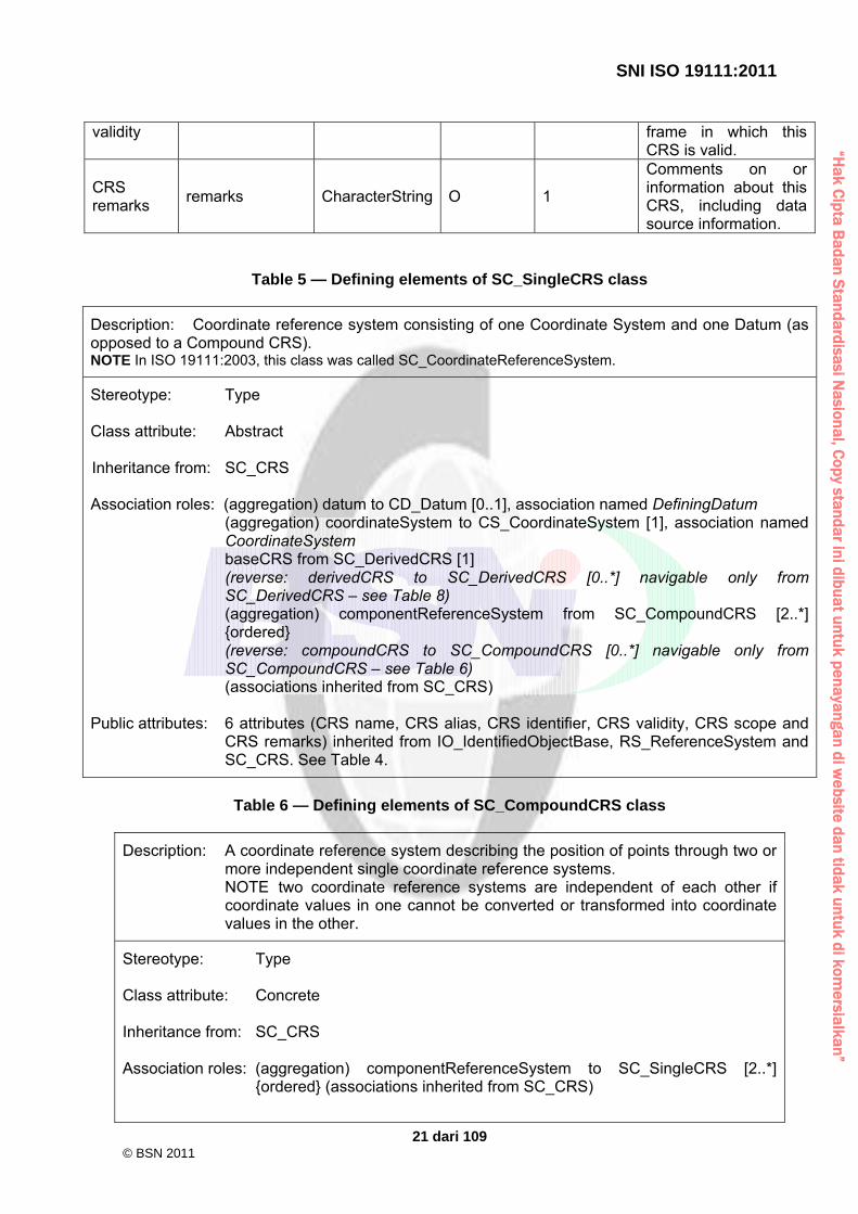
Table 5 — Defining elements of SC_SingleCRS class
Description: Coordinate reference system consisting of one Coordinate System and one Datum (as opposed to a Compound CRS). NOTE In ISO 19111:2003, this class was called SC_CoordinateReferenceSystem.
Stereotype: Type Class attribute: Abstract Inheritance from: SC_CRS Association roles: (aggregation) datum to CD_Datum [0..1], association named DefiningDatum
(aggregation) coordinateSystem to CS_CoordinateSystem [1], association named CoordinateSystem baseCRS from SC_DerivedCRS [1] (reverse: derivedCRS to SC_DerivedCRS [0..*] navigable only from SC_DerivedCRS – see Table 8) (aggregation) componentReferenceSystem from SC_CompoundCRS [2..*] ordered (reverse: compoundCRS to SC_CompoundCRS [0..*] navigable only from SC_CompoundCRS – see Table 6) (associations inherited from SC_CRS)
Public attributes: 6 attributes (CRS name, CRS alias, CRS identifier, CRS validity, CRS scope and
CRS remarks) inherited from IO_IdentifiedObjectBase, RS_ReferenceSystem and SC_CRS. See Table 4.
Table 6 — Defining elements of SC_CompoundCRS class
Description: A coordinate reference system describing the position of points through two or more independent single coordinate reference systems. NOTE two coordinate reference systems are independent of each other if coordinate values in one cannot be converted or transformed into coordinate values in the other.
Stereotype: Type Class attribute: Concrete Inheritance from: SC_CRS Association roles: (aggregation) componentReferenceSystem to SC_SingleCRS [2..*]
ordered (associations inherited from SC_CRS)
© BSN 2011

“Hak C
ipta Badan S
tandardisasi Nasional, C
opy standar ini dibuat untuk penayangan di website dan tidak untuk di kom
ersialkan”
SNI ISO 19111:2011
22 dari 109
Public attributes: 6 attributes (CRS name, CRS alias, CRS identifier, CRS validity, CRS scope and CRS remarks) inherited from IO_IdentifiedObjectBase, RS_ReferenceSystem and SC_CRS. See Table 4.
Table 7 — Defining elements of SC_GeneralDerivedCRS class
Description: A coordinate reference system that is defined by its coordinate conversion from another coordinate reference system.
Stereotype: Type Class attribute: Abstract Inheritance from: SC_SingleCRS Association roles: conversion to CC_Conversion [1], association named Definition
(associations inherited from SC_SingleCRS) Public attributes: 6 attributes inherited from IO_IdentifiedObjectBase,
RS_ReferenceSystem and SC_CRS. See Table 4.
Table 8 — Defining elements of SC_DerivedCRS class
Description: A single coordinate reference system that is defined by its coordinate conversion from another single coordinate reference system known as the base CRS. The base CRS cannot be a projected coordinate reference system.
Stereotype: Type Class attribute: Concrete Inheritance from: SC_GeneralDerivedCRS Association roles: baseCRS to SC_SingleCRS [1] (associations inherited from SC_
GeneralDerivedCRS, including … … (aggregation) coordinateSystem to CS_CoordinateSystem [1], association named CoordinateSystem)
Public attributes: 6 attributes inherited from IO_IdentifiedObjectBase, RS_ReferenceSystem
and SC_CRS (CRS name, CRS alias, CRS identifier, CRS validity, CRS scope and CRS remarks – see Table 4), plus:
Attribute name
UML identifier Data type Obligation Maximum Occurrence
Attribute description
Derived CRS type
derivedCRStype SC_DerivedCRSType M 1 Type of this derived coordinate reference system.
© BSN 2011
“Hak C
ipta Badan S
tandardisasi Nasional, C
opy standar ini dibuat untuk penayangan di website dan tidak untuk di kom
ersialkan”
SNI ISO 19111:2011
23 dari 109
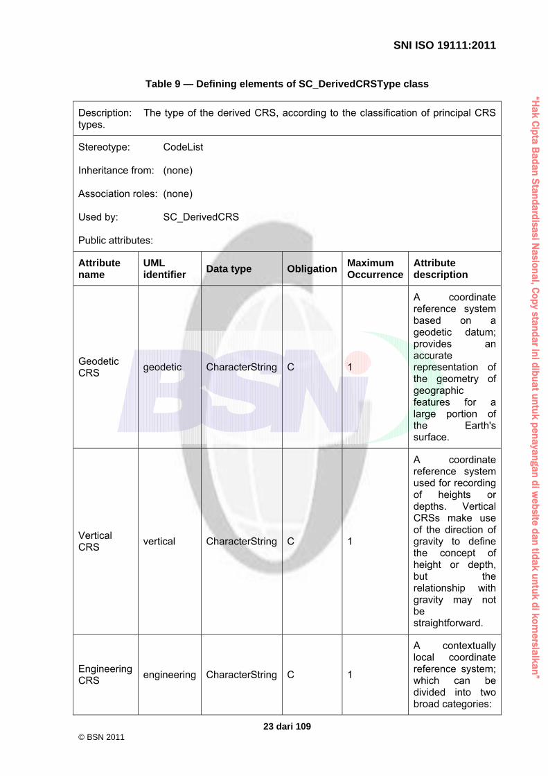
Table 9 — Defining elements of SC_DerivedCRSType class
Description: The type of the derived CRS, according to the classification of principal CRS types.
Stereotype: CodeList Inheritance from: (none) Association roles: (none) Used by: SC_DerivedCRS Public attributes:
Attribute name
UML identifier
Data type ObligationMaximum Occurrence
Attribute description
Geodetic CRS
geodetic CharacterString C 1
A coordinate reference system based on a geodetic datum; provides an accurate representation of the geometry of geographic features for a large portion of the Earth's surface.
Vertical CRS
vertical CharacterString C 1
A coordinate reference system used for recording of heights or depths. Vertical CRSs make use of the direction of gravity to define the concept of height or depth, but the relationship with gravity may not be straightforward.
Engineering CRS
engineering CharacterString C 1
A contextually local coordinate reference system; which can be divided into two broad categories:
© BSN 2011

“Hak C
ipta Badan S
tandardisasi Nasional, C
opy standar ini dibuat untuk penayangan di website dan tidak untuk di kom
ersialkan”
SNI ISO 19111:2011
24 dari 109
- Earth-fixed systems applied to engineering activities on or near the surface of the Earth; - CRSs on moving platforms such as road vehicles, vessels, aircraft or spacecraft.
Image CRS image CharacterString C 1
An engineering coordinate reference system applied to locations in images.
Condition: One and only one of the listed attributes shall be supplied.
Table 10 — Defining elements of SC_GeodeticCRS class
Description: A coordinate reference system associated with a geodetic datum.
Stereotype: Type Class attribute: Concrete Inheritance from: C_SingleCRS Association roles: (aggregation) datum to CD_GeodeticDatum [1], association named
DefiningDatum (aggregation) coordinateSystem to CS_GeodeticCS [1], association named CoordinateSystem baseCRS from ProjectedCRS [1] (reverse: derivedCRS to SC_ProjectedCRS [0..*] navigable only from SC_ProjectedCRS – see Table 11) (associations inherited from SC_SingleCRS)
Public Attributes: 6 attributes (CRS name, CRS alias, CRS identifier, CRS validity, CRS
scope and CRS remarks) inherited from IO_IdentifiedObjectBase, RS_ReferenceSystem and SC_CRS. See Table 4.
© BSN 2011

“Hak C
ipta Badan S
tandardisasi Nasional, C
opy standar ini dibuat untuk penayangan di website dan tidak untuk di kom
ersialkan”
SNI ISO 19111:2011
25 dari 109
Table 11 — Defining elements of SC_ProjectedCRS class
Description: A derived coordinate reference system which has a geodetic coordinate
reference system as its base CRS and is converted using a map projection.
Stereotype: Type Class attribute: Concrete Inheritance from: SC_GeneralDerivedCRS Association roles: baseCRS to SC_GeodeticCRS [1]
(aggregation) coordinateSystem to CS_CartesianCS [1], association named CoordinateSystem
(associations inherited from SC_ GeneralDerivedCRS)
Public Attributes: 6 attributes (CRS name, CRS alias, CRS identifier, CRS validity, CRS
scope and CRS remarks) inherited from IO_IdentifiedObjectBase, RS_ReferenceSystem and SC_CRS. See Table 4.
Table 12 — Defining elements of SC_EngineeringCRS class
Description: A contextually local coordinate reference system associated with an engineering datum and which can be divided into two broad categories:
- Earth-fixed systems applied to engineering activities on or near the
surface of the Earth; - CRSs on moving platforms such as road vehicles, vessels, aircraft or
spacecraft.
Stereotype: Type Class attribute: Concrete Inheritance from: SC_SingleCRS Association roles: (aggregation) datum to CD_EngineeringDatum [1], association named
DefiningDatum (aggregation) coordinateSystem to CS_EngineeringCS [1], association named CoordinateSystem (associations inherited from SC_SingleCRS
Public Attributes: 6 attributes (CRS name, CRS alias, CRS identifier, CRS validity, CRS
scope and CRS remarks) inherited from IO_IdentifiedObjectBase, RS_ReferenceSystem and SC_CRS. See Table 4.
© BSN 2011

“Hak C
ipta Badan S
tandardisasi Nasional, C
opy standar ini dibuat untuk penayangan di website dan tidak untuk di kom
ersialkan”
SNI ISO 19111:2011
26 dari 109
Table 13 — Defining elements of SC_ImageCRS class Description: A coordinate reference system associated with an image datum. Image
coordinate reference systems are treated as a separate sub-type because the definition of the associated Image Datum contains two attributes not relevant to other engineering datums.
Stereotype: Type Class attribute: Concrete Inheritance from: SC_SingleCRS Association roles: (aggregation) datum to CD_ImageDatum [1], association named
DefiningDatum (aggregation) coordinateSystem to CS_ImageCS [1], association named CoordinateSystem (associations inherited from SC_SingleCRS)
Public attributes: 6 attributes (CRS name, CRS alias, CRS identifier, CRS validity, CRS
scope and CRS remarks) inherited from IO_IdentifiedObjectBase, RS_ReferenceSystem and SC_CRS. See Table 4.
Table 14 — Defining elements of SC_VerticalCRS class
Description: A 1D coordinate reference system used for recording heights or depths.
Vertical CRSs make use of the direction of gravity to define the concept of height or depth, but the relationship with gravity may not be straightforward.
By implication, ellipsoidal heights (h) cannot be captured in a vertical coordinate reference system. Ellipsoidal heights cannot exist independently, but only as inseparable part of a 3D coordinate tuple defined in a geodetic 3D coordinate reference system.
Stereotype: Type Class attribute: Concrete Inheritance from: SC_SingleCRS Association roles: (aggregation) datum to CD_VerticalDatum [1], association named
DefiningDatum (aggregation) coordinateSystem to CS_VerticalCS [1], association named CoordinateSystem (associations inherited from SC_SingleCRS)
Public Attributes: 6 attributes (CRS name, CRS alias, CRS identifier, CRS validity, CRS
scope and CRS remarks) inherited from IO_IdentifiedObjectBase, RS_ReferenceSystem and SC_CRS. See Table 4.
© BSN 2011

“Hak C
ipta Badan S
tandardisasi Nasional, C
opy standar ini dibuat untuk penayangan di website dan tidak untuk di kom
ersialkan”
SNI ISO 19111:2011
27 dari 109
9 Coordinate System package 9.1 Introduction In this National Standard, the Coordinate System package models two main concepts: coordinate system and coordinate system axis. 9.2 Coordinate system A coordinate system shall be composed of a non-repeating sequence of coordinate system axes. One coordinate system may be used by multiple coordinate reference systems. The dimension of the coordinate space, the names, the units of measure, the directions and sequence of the axes all shall be part of the coordinate system definition. The number of axes shall be equal to the dimension of the space of which it describes the geometry. It is therefore not permitted to supply a coordinate tuple with two heights of different definition. The number of coordinates in a coordinate tuple shall be equal to the number of coordinate axes in the coordinate system. Coordinates in coordinate tuples shall be supplied in the order in which the coordinate system's axes are defined. In this National Standard, coordinate systems shall be divided into subtypes by the geometric properties of the coordinate space spanned and the geometric properties of the axes themselves (straight or curved; perpendicular or not). Certain subtypes of coordinate system shall be used only with specific subtypes of coordinate reference system as shown in the UML class diagram in Figure 8 and Table 15. For derived CRSs, the constraints on CS association shall be by derived CRS subtype and follow the constraints for the equivalent subtype of principle CRS. A description of coordinate system subtypes is included in Table 15. This National Standard additionally allows for user-defined coordinate systems. Each of these shall be used with one of the coordinate reference system subtypes described in Clause 8.
© BSN 2011

“Hak C
ipta Badan S
tandardisasi Nasional, C
opy standar ini dibuat untuk penayangan di website dan tidak untuk di kom
ersialkan”
SNI ISO 19111:2011
28 dari 109
Table 15 — Subtypes of coordinate system and constraints in its relationship with coordinate reference system
CS subtype Description Used with CRS
type(s) affine two- or three-dimensional coordinate system with straight axes
that are not necessarily orthogonal. Engineering
Image Cartesian two- or three-dimensional coordinate system which gives the
position of points relative to orthogonal straight axes. All axes shall have the same unit of measure.
Geodetic Projected
Engineering Image
cylindrical three-dimensional coordinate system consisting of a polar coordinate system extended by a straight coordinate axis perpendicular to the plane spanned by the polar coordinate system.
Engineering
ellipsoidal two- or three-dimensional coordinate system in which position is specified by geodetic latitude, geodetic longitude and (in the three-dimensional case) ellipsoidal height.
Geodetic
linear one-dimensional coordinate system that consists of the points that lie on the single axis described. Example: usage of the line feature representing a pipeline to describe points on or along that pipeline. This National Standard only lends itself to be used for simple (=continuous) linear systems. For a more extensive treatment of the subject, particularly as applied to the transportation industry, refer to ISO 19133 [7].
Engineering
polar two-dimensional coordinate system in which position is specified by distance from the origin and the angle between the line from origin to point and a reference direction.
Engineering
spherical three-dimensional coordinate system with one distance, measured from the origin, and two angular coordinates. Not to be confused with an ellipsoidal coordinate system based on an ellipsoid ‘degenerated’ into a sphere.
Geodetic Engineering
vertical one-dimensional coordinate system used to record the heights (or depths) of points dependent on the Earth’s gravity field. An exact definition is deliberately not provided as the complexities of the subject fall outside the scope of this specification.
Vertical
Coordinate systems are described further in B.2.1. 9.3 Coordinate system axis A coordinate system shall be composed of a non-repeating sequence of coordinate system axes. Each of its axes shall be completely characterized by a unique combination of axis name, axis abbreviation, axis direction and axis unit. Aliases for these attributes may be used as described in Clause 7. EXAMPLE 1 The combination Latitude, Lat, north, degree would lead to one instance of the object class “coordinate system axis”; the combination Latitude, , north, degree to another instance, the axis abbreviation being different. In this National Standard, usage of coordinate system axis names shall be constrained by geodetic custom, depending on the coordinate reference system type. These constraints are
© BSN 2011

“Hak C
ipta Badan S
tandardisasi Nasional, C
opy standar ini dibuat untuk penayangan di website dan tidak untuk di kom
ersialkan”
SNI ISO 19111:2011
29 dari 109
shown in Table 16. This constraint shall work in two directions. EXAMPLE 2 As “geodetic latitude“ and “geodetic longitude” are used as names for coordinate axes forming a geodetic coordinate reference system, these terms cannot also be used in another context. Aliases for these constrained names shall be permitted.
Table 16 — Naming constraints for coordinate system axis
CS type When used in CRS type Permitted coordinate system axis names
Cartesian geodetic geocentric X, geocentric Y, geocentric Z
Cartesian projected northing or southing, easting or westing
ellipsoidal geodetic geodetic latitude, geodetic longitude, [ellipsoidal height (if 3D)]
spherical geodetic spherical latitude, spherical longitude, geocentric radius
vertical vertical depth or gravity-related height
Image and engineering coordinate reference systems may make use of names specific to the local context or custom. Coordinate system axes are described further in B.2.2. 9.4 UML schema for the Coordinate System package Figure 7 shows the UML class diagram of the CS_CoordinateSystem package. The associations between Coordinate Reference System subtypes and Coordinate System subtypes are shown in the UML class diagram in Figure 8. The definitions of the object classes of the CS_CoordinateSystem package are provided in Tables 17 through 32.
Figure 7 — CS_CoordinateSystem package
© BSN 2011

“Hak C
ipta Badan S
tandardisasi Nasional, C
opy standar ini dibuat untuk penayangan di website dan tidak untuk di kom
ersialkan”
SNI ISO 19111:2011
30 dari 109
See Figure 8 for details of the association between the CS_CoordinateSystem and the SC_SingleCRS.
Figure 8 — Coordinate System type associations with Coordinate Reference System type
© BSN 2011

“Hak C
ipta Badan S
tandardisasi Nasional, C
opy standar ini dibuat untuk penayangan di website dan tidak untuk di kom
ersialkan”
SNI ISO 19111:2011
31 dari 109
Table 17 — Defining elements of CS_CoordinateSystem class
Description: A coordinate system (CS) is the non-repeating sequence of coordinate system axes that spans a given coordinate space. A CS is derived from a set of mathematical rules for specifying how coordinates in a given space are to be assigned to points. The coordinate values in a coordinate tuple shall be recorded in the order in which the coordinate system axes associations are recorded.
Stereotype: Type Class attribute: Abstract Inheritance from: IO_IdentifiedObject Association roles: (aggregation) axis to CS_CoordinateSystemAxis [1..*] ordered
(aggregation) coordinateSystem from SC_SingleCRS [1], association named CoordinateSystem (reverse: referenceSystem to SC_SingleCRS [0..*] navigable only from SC_SingleCRS – see Table 5)
Public attributes: 4 attributes (CS name, CS alias, CS identifier and CS remarks) inherited
from IO_IdentifiedObject and IO_IdentifiedObjectBase. See Tables 1 and 2.
Table 18 — Defining elements of CS_CartesianCS class
Description: A two- or three-dimensional coordinate system with orthogonal straight axes. In the 2D case, both axes shall have the same length unit; in the 3D case, all axes shall have the same length unit. A CartesianCS shall have two or three axis associations; the number of associations shall equal the dimension of the CS.
Stereotype: Type Class attribute: Concrete Inheritance from: CS_CoordinateSystem Association roles: (aggregation) coordinateSystem from SC_ProjectedCRS [1], association
named CoordinateSystem (reverse: referenceSystem to SC_ProjectedCRS [0..*] navigable only from SC_ProjectedCRS – see Table 11) (associations inherited from CS_CoordinateSystem)
Used by: CS_GeodeticCS
CS_EngineeringCS CS_ImageCS
Public attributes: 4 attributes (CS name, CS alias, CS identifier and CS remarks) inherited
from IO_IdentifiedObject and IO_IdentifiedObjectBase. See Tables 1 and 2.
© BSN 2011

“Hak C
ipta Badan S
tandardisasi Nasional, C
opy standar ini dibuat untuk penayangan di website dan tidak untuk di kom
ersialkan”
SNI ISO 19111:2011
32 dari 109
Table 19 — Defining elements of CS_AffineCS class
Description: A two- or three-dimensional coordinate system with straight axes that are not necessarily orthogonal. An AffineCS shall have two or three axis associations; the number of associations shall equal the dimension of the CS.
Stereotype: Type Class attribute: Concrete Inheritance from: CS_CoordinateSystem Used by: CS_EngineeringCS
CS_ImageCS Public attributes: 4 attributes (CS name, CS alias, CS identifier and CS remarks) inherited
from IO_IdentifiedObject and IO_IdentifiedObjectBase. See Tables 1 and 2.
Table 20 — Defining elements of CS_EllipsoidalCS class
Description: A two- or three-dimensional coordinate system in which position is specified by geodetic latitude, geodetic longitude, and (in the three-dimensional case) ellipsoidal height. An EllipsoidalCS shall have two or three associations; the number of associations shall equal the dimension of the CS.
Stereotype: Type Class attribute: Concrete Inheritance from: CS_CoordinateSystem Used by: CS_GeodeticCS Public attributes: 4 attributes (CS name, CS alias, CS identifier and CS remarks) inherited
from IO_IdentifiedObject and IO_IdentifiedObjectBase. See Tables 1 and 2.
© BSN 2011

“Hak C
ipta Badan S
tandardisasi Nasional, C
opy standar ini dibuat untuk penayangan di website dan tidak untuk di kom
ersialkan”
SNI ISO 19111:2011
33 dari 109
Table 21 — Defining elements of CS_SphericalCS class
Description: A three-dimensional coordinate system with one distance measured from the origin and two angular coordinates. Not to be confused with an ellipsoidal coordinate system based on an ellipsoid "degenerated" into a sphere. A SphericalCS shall have three axis associations.
Stereotype: Type Class attribute: Concrete Inheritance from: CS_CoordinateSystem Used by: CS_EngineeringCS Public attributes: 4 attributes (CS name, CS alias, CS identifier and CS remarks) inherited
from IO_IdentifiedObject and IO_IdentifiedObjectBase. See Tables 1 and 2.
Table 22 — Defining elements of CS_CylindricalCS class
Description: A three-dimensional coordinate system consisting of a polar coordinate system extended by a straight coordinate axis perpendicular to the plane spanned by the polar coordinate system. A CylindricalCS shall have three axis associations.
Stereotype: Type Class attribute: Concrete Inheritance from: CS_CoordinateSystem Used by: CS_EngineeringCS Public attributes: 4 attributes (CS name, CS alias, CS identifier and CS remarks) inherited
from IO_IdentifiedObject and IO_IdentifiedObjectBase. See Tables 1 and 2.
© BSN 2011

“Hak C
ipta Badan S
tandardisasi Nasional, C
opy standar ini dibuat untuk penayangan di website dan tidak untuk di kom
ersialkan”
SNI ISO 19111:2011
34 dari 109
Table 23 — Defining elements of CS_PolarCS class
Description: A two-dimensional coordinate system in which position is specified by the distance from the origin and the angle between the line from the origin to a point and a reference direction. A PolarCS shall have two axis associations.
Stereotype: Type Class attribute: Concrete Inheritance from: CS_CoordinateSystem Used by: CS_EngineeringCS Public attributes: 4 attributes (CS name, CS alias, CS identifier and CS remarks) inherited
from IO_IdentifiedObject and IO_IdentifiedObjectBase. See Tables 1 and 2.
Table 24 — Defining elements of CS_LinearCS class
Description: A one-dimensional coordinate system that consists of the points that lie on the single axis described. The associated coordinate is the distance – with or without offset – from the origin point, specified through the datum definition, to the point along the axis. Example: usage of the line feature representing a pipeline to describe points on or along that pipeline. A LinearCS shall have one axis association.
Stereotype: Type Class attribute: Concrete Inheritance from: CS_CoordinateSystem Used by: CS_EngineeringCS Public attributes: 4 attributes (CS name, CS alias, CS identifier and CS remarks) inherited
from IO_IdentifiedObject and IO_IdentifiedObjectBase. See Tables 1 and 2.
© BSN 2011

“Hak C
ipta Badan S
tandardisasi Nasional, C
opy standar ini dibuat untuk penayangan di website dan tidak untuk di kom
ersialkan”
SNI ISO 19111:2011
35 dari 109
Table 25 — Defining elements of CS_VerticalCS class
Description: A one-dimensional coordinate system used to record the heights or depths of points. Such a coordinate system is usually dependent on the Earth's gravity field. An exact definition is deliberately not provided as the complexities of the subject fall outside the scope of this document. A VerticalCS shall have one axis association.
Stereotype: Type Class attribute: Concrete Inheritance from: CS_CoordinateSystem Association roles: (aggregation) coordinateSystem from SC_VerticalCRS [1], association
named CoordinateSystem (reverse: referenceSystem to SC_VerticalCRS [0..*] navigable only from SC_VerticalCRS – see Table 14) (associations inherited from CS_CoordinateSystem)
Public attributes: 4 attributes (CS name, CS alias, CS identifier and CS remarks) inherited
from IO_IdentifiedObject and IO_IdentifiedObjectBase. See Tables 1 and 2.
Table 26 — Defining elements of CS_UserDefinedCS class
Description: A two- or three-dimensional coordinate system that consists of any combination of coordinate axes not covered by any other Coordinate System type. An example is a multilinear coordinate system which contains one coordinate axis that may have any 1D shape which has no intersections with itself. This non-straight axis is supplemented by one or two straight axes to complete a two- or three-dimensional coordinate system. The non-straight axis is typically incrementally straight or curved. A UserDefinedCS shall have two or three axis associations; the number of associations shall equal the dimension of the CS.
Stereotype: Type Class attribute: Concrete Inheritance from: CS_CoordinateSystem Used by: CS_EngineeringCS Public attributes: 4 attributes (CS name, CS alias, CS identifier and CS remarks) inherited
from IO_IdentifiedObject and IO_IdentifiedObjectBase. See Tables 1 and 2.
© BSN 2011

“Hak C
ipta Badan S
tandardisasi Nasional, C
opy standar ini dibuat untuk penayangan di website dan tidak untuk di kom
ersialkan”
SNI ISO 19111:2011
36 dari 109
Table 27 — Defining elements of CS_CoordinateSystemAxis class
Description: Definition of a coordinate system axis.
Stereotype: Type Class attribute: Concrete Inheritance from: IO_IdentifiedObject Association roles: (aggregation) axis from CS_CoordinateSystem [1..*] ordered
(reverse: coordinateSystem to CS_CoordinateSystem [0..*] navigable only from CS_CoordinateSystem – see Table 17)
Public attributes: 4 attributes (coordinate system axis name, coordinate system axis alias,
coordinate system axis identifier and coordinate system axis remarks) inherited from IO_IdentifiedObject and IO_IdentifiedObjectBase: see Tables 1 and 2, plus:
Attribute name
UML identifier Data type Obligation Maximum Occurrence
Attribute description
Coordinate system axis abbreviation
axisAbbrev CharacterString M 1 The abbreviation used for this coordinate system axis; this abbreviation is also used to identify the coordinates in the coordinate tuple. Examples are X and Y.
Coordinate system axis direction
axisDirection CS_AxisDirection M 1 Direction of this coordinate system axis (or in the case of Cartesian projected coordinates, the direction of this coordinate system axis locally). Examples: north or south, east or west, up or down. Within any set of coordinate system axes, only one of each pair of terms can
© BSN 2011

“Hak C
ipta Badan S
tandardisasi Nasional, C
opy standar ini dibuat untuk penayangan di website dan tidak untuk di kom
ersialkan”
SNI ISO 19111:2011
37 dari 109
be used. For Earth-fixed CRSs, this direction is often approximate and intended to provide a human interpretable meaning to the axis. When a geodetic datum is used, the precise directions of the axes may therefore vary slightly from this approximate direction. Note that an EngineeringCRS often requires specific descriptions of the directions of its coordinate system axes.
Coordinate system axis unit identifier
axisUnitID UnitOfMeasure M 1 Identifier of the unit used for this coordinate system axis. The value of a coordinate in a coordinate tuple shall be recorded using this unit.
Coordinate system axis minimum value
minimumValue Number O 1 The minimum value normally allowed for this axis, in the unit for the axis.
Coordinate system axis maximum value
maximumValue Number O 1 The maximum value normally allowed for this axis, in the unit for the axis.
Coordinate system axis range
rangeMeaning CS_RangeMeaning C 1 Meaning of axis value range specified by
© BSN 2011

“Hak C
ipta Badan S
tandardisasi Nasional, C
opy standar ini dibuat untuk penayangan di website dan tidak untuk di kom
ersialkan”
SNI ISO 19111:2011
38 dari 109
meaning minimumValue and maximumValue. This element shall be omitted when both minimumValue and maximumValue are omitted. It may be included when minimumValue and/or maximumValue are included. If this element is omitted when minimumValue or maximumValue are included, the meaning is unspecified.
© BSN 2011

“Hak C
ipta Badan S
tandardisasi Nasional, C
opy standar ini dibuat untuk penayangan di website dan tidak untuk di kom
ersialkan”
SNI ISO 19111:2011
39 dari 109
Table 28 — Defining elements of CS_AxisDirection class Description: The direction of positive increase in the coordinate value for a coordinate
system axis. Stereotype: CodeList Derived from: (none) Association roles: (none) Used by: CS_CoordinateSystemAxis Public attributes: Attribute name
UML identifier Data type ObligationMaximum Occurrence
Attribute description
north north CharacterString C 1 Axis positive direction is north. In a geodetic or projected CRS, north is defined through the geodetic datum. In an engineering CRS, north may be defined with respect to an engineering object rather than a geographical direction.
north-north-east
northNorthEast CharacterString C 1 Axis positive direction is approximately north-north-east.
north-east northEast CharacterString C 1 Axis positive direction is approximately north-east.
east-north-east
eastNorthEast CharacterString C 1 Axis positive direction is approximately east-north-east.
east east CharacterString C 1 Axis positive direction is /2 radians clockwise from north.
east- eastSouthEast CharacterString C 1 Axis positive
© BSN 2011

“Hak C
ipta Badan S
tandardisasi Nasional, C
opy standar ini dibuat untuk penayangan di website dan tidak untuk di kom
ersialkan”
SNI ISO 19111:2011
40 dari 109
south-east direction is approximately east-south-east.
south-east southEast CharacterString C 1 Axis positive direction is approximately south-east.
south-south-east
southSouthEast CharacterString C 1 Axis positive direction is approximately south-south-east.
south south CharacterString C 1 Axis positive direction is radians clockwise from north.
south-south-west
southSouthWest CharacterString C 1 Axis positive direction is approximately south-south-west.
south-west southWest CharacterString C 1 Axis positive direction is approximately south-west.
west-south-west
westSouthWest CharacterString C 1 Axis positive direction is approximately west-south-west.
west west CharacterString C 1 Axis positive direction is 3/2 radians clockwise from north.
west-north-west
westNorthWest CharacterString C 1 Axis positive direction is approximately west-north-west.
north-west northWest CharacterString C 1 Axis positive direction is approximately north-west.
north-north-west
northNorthWest CharacterString C 1 Axis positive direction is approximately north-north-west.
up up CharacterString C 1 Axis positive direction is up relative to
© BSN 2011

“Hak C
ipta Badan S
tandardisasi Nasional, C
opy standar ini dibuat untuk penayangan di website dan tidak untuk di kom
ersialkan”
SNI ISO 19111:2011
41 dari 109
gravity.
down down CharacterString C 1 Axis positive direction is down relative to gravity.
Geocentric X
geocentricX CharacterString C 1 Axis positive direction is in the equatorial plane from the centre of the modelled Earth towards the intersection of the equator with the prime meridian.
Geocentric Y
geocentricY CharacterString C 1 Axis positive direction is in the equatorial plane from the centre of the modelled Earth towards the intersection of the equator and the meridian /2 radians eastwards from the prime meridian.
Geocentric Z
geocentricZ CharacterString C 1 Axis positive direction is from the centre of the modelled Earth parallel to its rotation axis and towards its north pole.
column-positive
columnPositive CharacterString C 1 Axis positive direction is towards higher pixel column.
column-negative
columnNegative CharacterString C 1 Axis positive direction is towards lower pixel column.
row-positive
rowPositive CharacterString C 1 Axis positive direction is towards higher
© BSN 2011

“Hak C
ipta Badan S
tandardisasi Nasional, C
opy standar ini dibuat untuk penayangan di website dan tidak untuk di kom
ersialkan”
SNI ISO 19111:2011
42 dari 109
pixel row.
row-negative
rowNegative CharacterString C 1 Axis positive direction is towards lower pixel row.
display-right
displayRight CharacterString C 1 Axis positive direction is right in display.
display-left displayLeft CharacterString C 1 Axis positive direction is left in display.
display-up displayUp CharacterString C 1 Axis positive direction is towards top of approximately vertical display surface.
display-down
displayDown CharacterString C 1 Axis positive direction is towards bottom of approximately vertical display surface.
Condition: One and only one of the listed attributes shall be supplied.
Table 29 — Defining elements of CS_RangeMeaning class
Description: Meaning of the axis value range specified through minimumValue and maximumValue.
Stereotype: CodeList Inheritance from: (none) Association roles: (none) Used by: CS_CoordinateSystemAxis Public attributes:
Attribute name
UML identifier
Data type ObligationMaximum Occurrence
Attribute description
Exact exact CharacterString C 1 Any value between and including minimumValue and maximumValue is valid.
© BSN 2011

“Hak C
ipta Badan S
tandardisasi Nasional, C
opy standar ini dibuat untuk penayangan di website dan tidak untuk di kom
ersialkan”
SNI ISO 19111:2011
43 dari 109
Wraparound wraparound CharacterString C 1 The axis is continuous with values wrapping around at the minimumValue and maximumValue. Values with the same meaning repeat modulo the difference between maximumValue and minimumValue.
Condition: One and only one of the listed attributes shall be supplied.
Table 30 — Defining elements of CS_GeodeticCS class
Description: A coordinate system used by a Geodetic CRS. It shall be one of the following: a Cartesian coordinate system; an ellipsoidal coordinate system; or a spherical coordinate system.
Stereotype: Union Realization of: CS_CoordinateSystem. As such, it must implement all inherited
operations and associations. Furthermore, it must support all inherited attributes, at least as “read only”.
Association roles: (aggregation) coordinateSystem from SC_GeodeticCRS [1], association
named CoordinateSystem (reverse: referenceSystem to SC_GeodeticCRS [0..*] navigable only from SC_GeodeticCRS – see Table 10) (aggregation) cartesianCS to CS_CartesianCS [1] (aggregation) ellipsoidalCS to CS_EllipsoidalCS [1] (aggregation) sphericalCS to CS_SphericalCS [1] union (one of) constraint on cartesianCS, ellipsoidalCS and sphericalCS associations (associations inherited from CS_CoordinateSystem)
Public attributes: (none)
© BSN 2011

“Hak C
ipta Badan S
tandardisasi Nasional, C
opy standar ini dibuat untuk penayangan di website dan tidak untuk di kom
ersialkan”
SNI ISO 19111:2011
44 dari 109
Table 31 — Defining elements of CS_EngineeringCS class
Description: A coordinate system used by an Engineering CRS. It shall be one of the following: an affine coordinate system; a Cartesian coordinate system; a cylindrical coordinate system; a linear coordinate system; a polar coordinate system; a spherical coordinate system; or a user-defined coordinate system.
Stereotype: Union Realization of: CS_CoordinateSystem. As such, it must implement all inherited
operations and associations. Furthermore, it must support all inherited attributes, at least as “read only”.
Association roles: (aggregation) coordinateSystem from SC_EngineeringCRS [1],
association named CoordinateSystem (reverse: referenceSystem to SC_EngineeringCRS [0..*] navigable only from SC_EngineeringCRS – see Table 12) (aggregation) affineCS to CS_AffineCS [1] (aggregation) cartesianCS to CS_CartesianCS [1] (aggregation) cylindricalCS to CS_ CylindricalCS [1] (aggregation) linearCS to CS_LinearCS [1] (aggregation) polarCS to CS_PolarCS [1] (aggregation) sphericalCS to CS_SphericalCS [1] (aggregation) userDefinedCS to CS_UserDefinedCS [1] union (one of) constraint on affineCS, cartesianCS, cylindricalCS, linearCS, polar CS, sphericalCS and userDefinedCS associations (associations inherited from CS_CoordinateSystem)
Public attributes: (none)
Table 32 — Defining elements of CS_ImageCS class
Description: A coordinate system used by an Image CRS. It shall be either an affine coordinate system or a Cartesian coordinate system.
Stereotype: Union Realization of: CS_CoordinateSystem. As such it must implement all inherited operations
and associations. Furthermore it must support all inherited attributes, at least as “read only”.
Association roles: (aggregation) coordinateSystem from SC_ImageCRS [1], association
named CoordinateSystem (reverse: referenceSystem to SC_ImageCRS [0..*] navigable only from SC_ImageCRS – see Table 13) (aggregation) affineCS to CS_AffineCS [1] (aggregation) cartesianCS to CS_CartesianCS [1] union (one of) constraint on affineCS and cartesianCS associations (associations inherited from CS_CoordinateSystem)
Public attributes: (none)
© BSN 2011
“Hak C
ipta Badan S
tandardisasi Nasional, C
opy standar ini dibuat untuk penayangan di website dan tidak untuk di kom
ersialkan”
SNI ISO 19111:2011
45 dari 109
10 Datum package 10.1 Types of datums A datum can be used as the basis for one-, two- or three-dimensional systems. For geodetic and vertical coordinate reference systems, the datum shall relate the coordinate system to the Earth. With other types of coordinate reference systems, the datum may relate the coordinate system to another physical or virtual object. In some applications of an Engineering CRS, the object may be a platform moving relative to the Earth. In these applications, the datum itself is not time-dependent, but any transformations of the associated coordinates to an Earth-fixed or other coordinate reference system shall contain time-dependent parameters. In this National Standard, four subtypes of datum shall be recognized: geodetic; vertical; engineering; and image. Each datum subtype can be associated only with specific subtypes of coordinate reference systems, as shown in Figure 10. Constraints on geodetic datum are detailed below. Datums are described further in B.3. 10.2 Geodetic datum 10.2.1 Prime meridian If the datum subtype is geodetic, the description of the origin from which longitude values are specified – the prime meridian – shall be mandatory. Most geodetic datums use Greenwich as their prime meridian. Default values for the attributes prime meridian name and Greenwich Longitude shall be “Greenwich” and 0, respectively. If the prime meridian name is “Greenwich” then the value of Greenwich Longitude shall be 0 degrees. The data attributes of prime meridian are described in Table 35. 10.2.2 Ellipsoid If the datum subtype is geodetic, the description of one associated ellipsoid shall be mandatory. An ellipsoid specification shall not be provided if the datum subtype is not geodetic. An ellipsoid shall be defined either by its semi-major axis and inverse flattening, or by its semi-major axis and semi-minor axis, or as being a sphere. The data attributes of ellipsoid are described in Tables 36 and 37. 10.3 UML schema for the Datum package Figure 9 shows the UML class diagram for the CD_Datum package. There are restrictions on the associations between Coordinate Reference System subtypes and Datum subtypes which are shown in the UML class diagram in Figure 10. The definition of the object classes of this package is provided in Tables 33 through 41.
© BSN 2011

“Hak C
ipta Badan S
tandardisasi Nasional, C
opy standar ini dibuat untuk penayangan di website dan tidak untuk di kom
ersialkan”
SNI ISO 19111:2011
46 dari 109
Figure 9 — CD_Datum package See Figure 10 for details of the associations between the CD_Datum and the SC_SingleCRS.
Figure 10 — Datum type associations with Coordinate Reference System type
© BSN 2011
“Hak C
ipta Badan S
tandardisasi Nasional, C
opy standar ini dibuat untuk penayangan di website dan tidak untuk di kom
ersialkan”
SNI ISO 19111:2011
47 dari 109
Table 33 — Defining elements of CD_Datum class
Description: A datum specifies the relationship of a coordinate system to an object, thus creating a coordinate reference system. For geodetic and vertical coordinate reference systems, the datum relates the coordinate system to the Earth. With other types of coordinate reference systems, the datum may relate the coordinate system to another physical or virtual object. A datum uses a parameter or set of parameters that determine the location of the origin of the coordinate reference system. Each datum subtype can be associated with only specific types of coordinate reference systems.
Stereotype: Type Class attribute: Abstract Inheritance from: IO_IdentifiedObject Association roles: (aggregation) datum from SC_SingleCRS [0..1], association named
DefiningDatum (reverse: referenceSystem to SC_SingleCRS [0..*] navigable only from SC_SingleCRS – see Table 5)
Public attributes: 4 attributes (datum name, datum alias, datum identifier and datum remarks) inherited from IO_IdentifiedObject and IO_IdentifiedObjectBase (see Tables 1 and 2), plus:
Attribute name
UML identifier Data type Obligation Maximum Occurrence
Attribute description
Datum anchor
anchorDefinition CharacterString O 1 The datum definition – a description, possibly including coordinates of an identified point or points, of the relationship used to anchor the coordinate system to the Earth or alternate object. - For a geodetic datum, this anchor may be a point known as the fundamental point, which is traditionally the point where the relationship between geoid and ellipsoid is defined, together with a direction from that point. In other cases, the
© BSN 2011

“Hak C
ipta Badan S
tandardisasi Nasional, C
opy standar ini dibuat untuk penayangan di website dan tidak untuk di kom
ersialkan”
SNI ISO 19111:2011
48 dari 109
anchor may consist of a number of points. In those cases, the parameters defining the geoid/ellipsoid relationship have then been averaged for these points, and the coordinates of the points adopted as the datum definition. - For an engineering datum, the anchor may be an identified physical point with the orientation defined relative to the object. - For an image datum, the anchor is usually either the centre of the image or the corner of the image. The coordinate system orientation is defined through the CS_AxisDirection class.
Datum realization epoch
realizationEpoch Date O 1 The time after which this datum definition is valid. This time may be precise (e.g. 1997.0 for IRTF97) or merely a year [e.g. 1986 for NAD83(86)]. In the latter case, the epoch usually refers to the year in which
© BSN 2011

“Hak C
ipta Badan S
tandardisasi Nasional, C
opy standar ini dibuat untuk penayangan di website dan tidak untuk di kom
ersialkan”
SNI ISO 19111:2011
49 dari 109
a major recalculation of the geodetic control network, underlying the datum, was executed or initiated. An old datum may remain valid after a new datum is defined. Alternatively, a datum may be replaced by a later datum, in which case the realization epoch for the new datum defines the upper limit for the validity of the replaced datum.
Datum validity
domainOfValidity EX_Extent O 1 Area or region or time frame in which this datum is valid.
Datum scope
scope CharacterString M N Description of usage, or limitations of usage, for which this datum is valid. If unknown, enter "not known".
© BSN 2011

“Hak C
ipta Badan S
tandardisasi Nasional, C
opy standar ini dibuat untuk penayangan di website dan tidak untuk di kom
ersialkan”
SNI ISO 19111:2011
50 dari 109
Table 34 — Defining elements of CD_GeodeticDatum class
Description: A geodetic datum defines the location and precise orientation in three-dimensional space of a defined ellipsoid (or sphere) that approximates the shape of the earth, or of a Cartesian coordinate system centered in this ellipsoid (or sphere).
Stereotype: Type Class attribute: Concrete Inheritance from: CD_Datum
Association roles: (aggregation) ellipsoid to CD_Ellipsoid [1] (aggregation) primeMeridian to CD_PrimeMeridian [1] (aggregation) datum from SC_GeodeticCRS [1], association named DefiningDatum (reverse: referenceSystem to SC_GeodeticCRS [0..*] navigable only from SC_GeodeticCRS – see Table 10)
Public attributes: 8 attributes (datum name, datum alias, datum identifier, datum remarks,
datum anchor, datum realization epoch, datum validity and datum scope) inherited from IO_IdentifiedObject, IO_IdentifiedObjectBase and CD_Datum. See Tables 1, 2 and 33.
Table 35 — Defining elements of CD_PrimeMeridian class
Description: A prime meridian defines the origin from which longitude values are determined.
NOTE The default value for prime meridian name is “Greenwich”. When the default applies, the value for the greenwichLongitude shall be 0 (degrees).
Stereotype: Type Class attribute: Concrete Inheritance from: IO_IdentifiedObject
Association roles: (aggregation) primeMeridian from CD_GeodeticDatum [1] (reverse: datum to CD_GeodeticDatum [0..*] navigable only from CD_GeodeticDatum – see Table 34)
Public attributes: 4 attributes (prime meridian name, prime meridian alias, prime meridian
identifier and prime meridian remarks) inherited from IO_IdentifiedObject and IO_IdentifiedObjectBase (see Tables 1 and 2), plus:
Attribute name
UML identifier Data type
Obligation Maximum Occurrence
Attribute description
Prime greenwichLongitude Angle M 1 Longitude of the
© BSN 2011

“Hak C
ipta Badan S
tandardisasi Nasional, C
opy standar ini dibuat untuk penayangan di website dan tidak untuk di kom
ersialkan”
SNI ISO 19111:2011
51 dari 109
meridian Greenwich longitude
prime meridian measured from the Greenwich meridian, positive eastward. Default value: 0 degrees. NOTE If the value of the prime meridian name is “Greenwich” then the value of greenwichLongitude shall be 0 degrees.
Table 36 — Defining elements of CD_Ellipsoid class
Description: An ellipsoid is a geometric figure that can be used to describe the approximate shape of the Earth. In mathematical terms, it is a surface formed by the rotation of an ellipse about its minor axis.
Stereotype: Type Class attribute: Concrete Inheritance from: IO_IdentifiedObject Association roles: (aggregation) ellipsoid from CD_GeodeticDatum [1] (reverse: datum to CD_GeodeticDatum [0..*] navigable only from CD_GeodeticDatum – see Table 34) Public attributes: 4 attributes (ellipsoid name, ellipsoid alias, ellipsoid identifier and ellipsoid remarks)
inherited from IO_IdentifiedObject and IO_IdentifiedObjectBase (see Tables 1 and 2), plus:
Attribute name
UML identifier Data type Obligation Maximum Occurrence
Attribute description
Length of semi-major axis
semiMajorAxis Length M 1 Length of the semi-major axis of the ellipsoid.
Second defining parameter
secondDefiningParameter CD_SecondDefining Parameter
M 1 Definition of the second parameter that describes the shape of this ellipsoid.
© BSN 2011

“Hak C
ipta Badan S
tandardisasi Nasional, C
opy standar ini dibuat untuk penayangan di website dan tidak untuk di kom
ersialkan”
SNI ISO 19111:2011
52 dari 109
Table 37 — Defining elements of CD_SecondDefiningParameter class
Description: Definition of the second parameter that defines the shape of an ellipsoid. An ellipsoid requires two defining parameters: a semimajor axis and inverse flattening or a semi-major axis and a semi-minor axis. When the reference body is a sphere rather than an ellipsoid, only a single defining parameter is required, namely the radius of the sphere; in that case, the semi-major axis “degenerates” into the radius of the sphere.
Stereotype: Union Inheritance from: (none) Association roles: (none) Used by: CD_Ellipsoid Public attributes:
Attribute name
UML identifier Data type
Obligation Maximum Occurrence
Attribute description
Inverse flattening
inverseFlattening Scale C 1 Inverse flattening value of the ellipsoid.
Length of semi-minor axis
semiMinorAxis Length C 1 Length of the semi-minor axis of the ellipsoid.
“Ellipsoid = Sphere” indicator
isSphere Boolean C 1 The ellipsoid is degenerate and is actually a sphere. The sphere is completely defined by the semi-major axis, which is the radius of the sphere. This attribute has the value “true” if the figure is a sphere.
Condition: One and only one of these three elements shall be supplied.
© BSN 2011
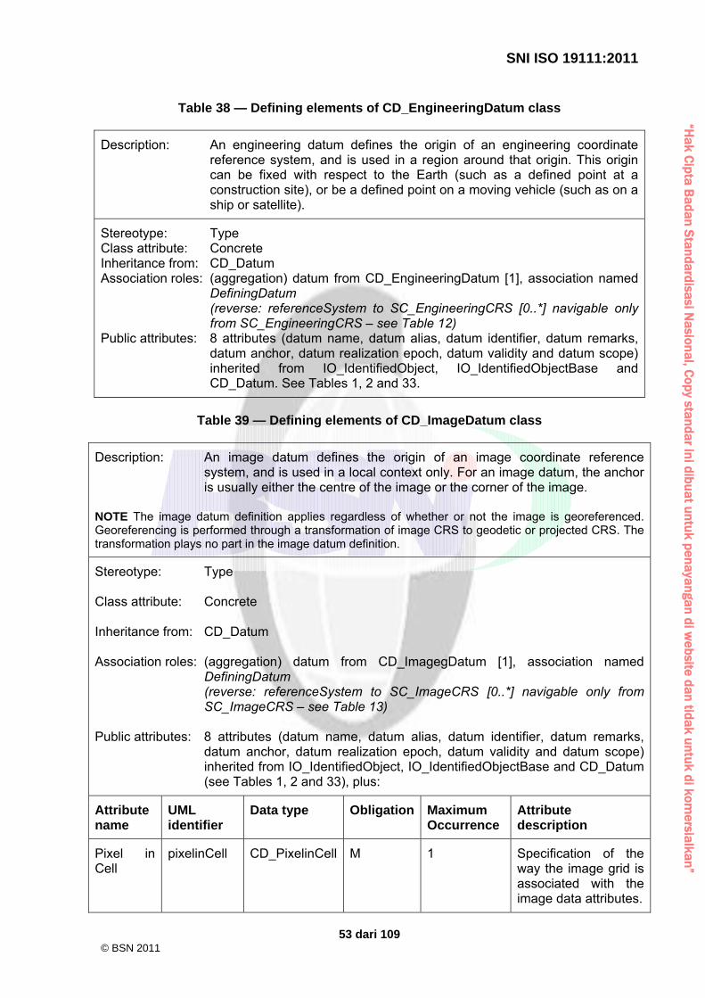
“Hak C
ipta Badan S
tandardisasi Nasional, C
opy standar ini dibuat untuk penayangan di website dan tidak untuk di kom
ersialkan”
SNI ISO 19111:2011
53 dari 109
Table 38 — Defining elements of CD_EngineeringDatum class
Description: An engineering datum defines the origin of an engineering coordinate reference system, and is used in a region around that origin. This origin can be fixed with respect to the Earth (such as a defined point at a construction site), or be a defined point on a moving vehicle (such as on a ship or satellite).
Stereotype: Type Class attribute: Concrete Inheritance from: CD_Datum Association roles: (aggregation) datum from CD_EngineeringDatum [1], association named
DefiningDatum (reverse: referenceSystem to SC_EngineeringCRS [0..*] navigable only from SC_EngineeringCRS – see Table 12)
Public attributes: 8 attributes (datum name, datum alias, datum identifier, datum remarks, datum anchor, datum realization epoch, datum validity and datum scope) inherited from IO_IdentifiedObject, IO_IdentifiedObjectBase and CD_Datum. See Tables 1, 2 and 33.
Table 39 — Defining elements of CD_ImageDatum class
Description: An image datum defines the origin of an image coordinate reference system, and is used in a local context only. For an image datum, the anchor is usually either the centre of the image or the corner of the image.
NOTE The image datum definition applies regardless of whether or not the image is georeferenced. Georeferencing is performed through a transformation of image CRS to geodetic or projected CRS. The transformation plays no part in the image datum definition.
Stereotype: Type Class attribute: Concrete Inheritance from: CD_Datum Association roles: (aggregation) datum from CD_ImagegDatum [1], association named
DefiningDatum (reverse: referenceSystem to SC_ImageCRS [0..*] navigable only from SC_ImageCRS – see Table 13)
Public attributes: 8 attributes (datum name, datum alias, datum identifier, datum remarks,
datum anchor, datum realization epoch, datum validity and datum scope) inherited from IO_IdentifiedObject, IO_IdentifiedObjectBase and CD_Datum (see Tables 1, 2 and 33), plus:
Attribute name
UML identifier
Data type Obligation Maximum Occurrence
Attribute description
Pixel in Cell
pixelinCell CD_PixelinCell M 1 Specification of the way the image grid is associated with the image data attributes.
© BSN 2011

“Hak C
ipta Badan S
tandardisasi Nasional, C
opy standar ini dibuat untuk penayangan di website dan tidak untuk di kom
ersialkan”
SNI ISO 19111:2011
54 dari 109
Table 40 — Defining elements of CD_PixelinCell class
Description: Specification of the way the image grid is associated with the image data attributes.
Stereotype: CodeList Inheritance from: (none) Association roles: (none) Used by: CD_ImageDatum Public attributes:
Attribute name
UML identifier
Data type Obligation
Maximum Occurrence
Attribute description
Cell center
cellCenter CharacterString
C 1 The origin of the image coordinate system is the centre of a grid cell or image pixel.
Cell corner
cellCorner CharacterString
C 1 The origin of the image coordinate system is the corner of a grid cell, or half-way between the centres of adjacent image pixels.
Condition: One and only one of the listed attributes shall be supplied.
Table 41 — Defining elements of CD_VerticalDatum class
Description: A textual description and/or a set of parameters identifying a particular reference level surface used as a zero-height or zero-depth surface, including its position with respect to the Earth.
Stereotype: Type Class attribute: Concrete Inheritance from: CD_Datum Association roles: (aggregation) datum to CD_VerticalDatum [1], association named
DefiningDatum (reverse: referenceSystem to SC_VerticalCRS [0..*] navigable only from SC_VerticalCRS – see Table 14)
Public attributes: 8 attributes (datum name, datum alias, datum identifier, datum remarks,
datum anchor, datum realization epoch, datum validity and datum scope) inherited from IO_IdentifiedObject, IO_IdentifiedObjectBase and CD_Datum. See Tables 1, 2 and 33.
© BSN 2011

“Hak C
ipta Badan S
tandardisasi Nasional, C
opy standar ini dibuat untuk penayangan di website dan tidak untuk di kom
ersialkan”
SNI ISO 19111:2011
55 dari 109
11 Coordinate Operation package 11.1 General characteristics of coordinate operations In this National Standard, the following subtypes of coordinate operation shall be recognized. a) A coordinate conversion changes coordinates from one coordinate reference system to
another based on the same datum. b) A coordinate transformation changes coordinates from one coordinate reference system
to another coordinate reference system which is based on a different datum. c) A concatenated coordinate operation is a non-repeating sequence of coordinate
conversions and/or coordinate transformations. d) A pass-through coordinate operation allows a subset of a coordinate tuple to be
subjected to a coordinate operation; coordinates in the coordinate tuple other than the subset remain unchanged.
Coordinate operations are further described in B.4. A coordinate operation may be time-varying, and shall be time-varying if the source and target CRS are moving relative to each other. When the coordinate operation is time-varying, the coordinate operation method used shall also be time-varying, and some of the parameters used by that coordinate operation method will involve time. EXAMPLE Some of the parameters may have time, velocity, and/or acceleration values and units. 11.2 UML schema for the Coordinate Operation package Figures 11 and 12 contain the two parts of the UML class diagram for the CC_CoordinateOperation package. As indicated by the note in Figure 11, Figure 12 shows additional classes and associations from the CC_SingleOperation class shown in Figure 11. The definition of the object classes of the CC_CoordinateOperation package is provided in Tables 42 through 56.
© BSN 2011

“Hak C
ipta Badan S
tandardisasi Nasional, C
opy standar ini dibuat untuk penayangan di website dan tidak untuk di kom
ersialkan”
SNI ISO 19111:2011
56 dari 109
Figure 11 — CC_CoordinateOperation package part 1
© BSN 2011

“Hak C
ipta Badan S
tandardisasi Nasional, C
opy standar ini dibuat untuk penayangan di website dan tidak untuk di kom
ersialkan”
SNI ISO 19111:2011
57 dari 109
Figure 12 — CC_CoordinateOperation package part 2
© BSN 2011

“Hak C
ipta Badan S
tandardisasi Nasional, C
opy standar ini dibuat untuk penayangan di website dan tidak untuk di kom
ersialkan”
SNI ISO 19111:2011
58 dari 109
Table 42 — Defining elements of CC_CoordinateOperation class
Description: A mathematical operation on coordinates that transforms or converts coordinates to another coordinate reference system. Many but not all coordinate operations (from CRS A to CRS B) also uniquely define the inverse coordinate operation (from CRS B to CRS A). In some cases, the coordinate operation method algorithm for the inverse coordinate operation is the same as for the forward algorithm, but the signs of some coordinate operation parameter values have to be reversed. In other cases, different algorithms are required for the forward and inverse coordinate operations, but the same coordinate operation parameter values are used. If (some) entirely different parameter values are needed, a different coordinate operation shall be defined.
Stereotype: Type Class attribute: Abstract Inheritance from: IO_IdentifiedObject Association roles: sourceCRS to SC_CRS [0..1], association named Source
targetCRS to SC_CRS [0..1], association named Target (aggregation) coordOperation from CC_ConcatenatedOperation [2..*] ordered (reverse: concatOperation to CC_ConcatenatedOperation [0..*] navigable only from CC_ConcatenatedOperation – see Table 46) coordOperation from CC_PassThroughOperation [1] (reverse: passThruOperation to CC_PassThroughOperation [0..*] navigable only from CC_PassThroughOperation – see Table 47) (associations inherited from IO_IdentifiedObject) Note attached to associations Source and Target: The “sourceCRS” and “targetCRS” associations are mandatory for coordinate transformations only. Coordinate conversions have a source CRS and a target CRS that are NOT specified through these associations, but through associations from GeneralDerivedCRS to SingleCRS. For a concatenated coordinate operation sequence of n coordinate operations: source CRS (concatenated coordinate operation) = source CRS (coordinate operation step 1) target CRS (coordinate operation step i) = source CRS (coordinate operation step i + 1); i = 1 ...(n −1) target CRS (concatenated coordinate operation) = target CRS (coordinate operation step n) Instead of a forward coordinate operation, an inverse coordinate operation may be used for one or more of the coordinate operation steps mentioned above, if the inverse coordinate operation is uniquely defined by the forward coordinate operation method.
Public attributes: 4 attributes (coordinate operation name, coordinate operation alias,
coordinate operation identifier and coordinate operation remarks) inherited from IO_IdentifiedObject and IO_IdentifiedObjectBase (see Tables 1 and 2), plus:
© BSN 2011

“Hak C
ipta Badan S
tandardisasi Nasional, C
opy standar ini dibuat untuk penayangan di website dan tidak untuk di kom
ersialkan”
SNI ISO 19111:2011
59 dari 109
Attribute name
UML identifier Data type Obligation Maximum Occurrence
Attribute description
Coordinate operation version
operationVersion CharacterString C 1 Version of the coordinate transformation (i.e. instantiation due to the stochastic nature of the parameters). Mandatory when describing a coordinate transformation, and should not be supplied for a coordinate conversion.
Coordinate operation validity
domainOfValidity EX_Extent O 1 Area or region or time frame in which this coordinate operation is valid.
Coordinate operation scope
scope CharacterString M N Description of usage, or limitations of usage, for which this coordinate operation is valid. If unknown, enter “not known”.
Coordinate operation accuracy
coordinateOperati onAccuracy
DQ_Positional Accuracy
O N Estimate(s) of the impact of this coordinate operation on point accuracy. Gives position error estimates for target coordinates of this coordinate operation, assuming no
© BSN 2011

“Hak C
ipta Badan S
tandardisasi Nasional, C
opy standar ini dibuat untuk penayangan di website dan tidak untuk di kom
ersialkan”
SNI ISO 19111:2011
60 dari 109
errors in source coordinates.
Table 43 — Defining elements of CC_SingleOperation class
Description: A single (not concatenated) coordinate operation.
Stereotype: Type Class attribute: Abstract Inheritance from: CC_CoordinateOperation Association roles: method to CC_OperationMethod [1]
(composition) parameterValue to CC_GeneralParameterValue [0..*] (associations inherited from CC_CoordinateOperation)
Public attributes: 8 attributes (coordinate operation name, coordinate operation alias, coordinate operation identifier, coordinate operation remarks, coordinate operation version, coordinate operation validity, coordinate operation scope and coordinate operation accuracy) inherited from IO_IdentifiedObject and IO_IdentifiedObjectBase and CC_CoordinateOperation. See Tables 1, 2 and 42.
Table 44 — Defining elements of CC_Transformation class
Description: A coordinate operation through which the input and output coordinates are referenced to different datums. The parameters of a coordinate transformation are empirically derived from data containing the coordinates of a series of points in both coordinate reference systems. This computational process is usually “over-determined”, allowing derivation of error (or accuracy) estimates for the coordinate transformation. Also, the stochastic nature of the parameters may result in multiple (different) versions of the same coordinate transformations between the same source and target CRSs.
Stereotype: Type Class attribute: Concrete Inheritance from: CC_SingleOpereration Association roles: (associations inherited from CC_SingleOperation) Public attributes: 8 attributes (coordinate operation name, coordinate operation alias,
coordinate operation identifier, coordinate operation remarks, coordinate operation version, coordinate operation validity, coordinate operation scope and, coordinate operation accuracy) inherited from IO_IdentifiedObject and IO_IdentifiedObjectBase and CC_CoordinateOperation (see Tables 1, 2 and 42), one of which is modified:
Attribute name
UML identifier Data type Obligation Maximum Occurrence
Description
Coordinate operation version
operationVersion CharacterString M 1 Version of the coordinate transformation (i.e. instantiation
© BSN 2011
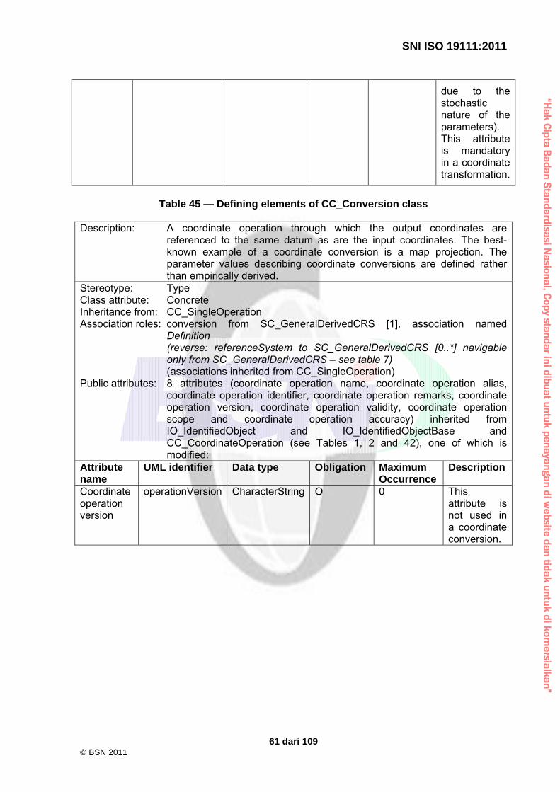
“Hak C
ipta Badan S
tandardisasi Nasional, C
opy standar ini dibuat untuk penayangan di website dan tidak untuk di kom
ersialkan”
SNI ISO 19111:2011
61 dari 109
due to the stochastic nature of the parameters). This attribute is mandatory in a coordinate transformation.
Table 45 — Defining elements of CC_Conversion class
Description: A coordinate operation through which the output coordinates are
referenced to the same datum as are the input coordinates. The best-known example of a coordinate conversion is a map projection. The parameter values describing coordinate conversions are defined rather than empirically derived.
Stereotype: Type Class attribute: Concrete Inheritance from: CC_SingleOperation Association roles: conversion from SC_GeneralDerivedCRS [1], association named
Definition (reverse: referenceSystem to SC_GeneralDerivedCRS [0..*] navigable only from SC_GeneralDerivedCRS – see table 7) (associations inherited from CC_SingleOperation)
Public attributes: 8 attributes (coordinate operation name, coordinate operation alias, coordinate operation identifier, coordinate operation remarks, coordinate operation version, coordinate operation validity, coordinate operation scope and coordinate operation accuracy) inherited from IO_IdentifiedObject and IO_IdentifiedObjectBase and CC_CoordinateOperation (see Tables 1, 2 and 42), one of which is modified:
Attribute name
UML identifier Data type Obligation Maximum Occurrence
Description
Coordinate operation version
operationVersion CharacterString O 0 This attribute is not used in a coordinate conversion.
© BSN 2011

“Hak C
ipta Badan S
tandardisasi Nasional, C
opy standar ini dibuat untuk penayangan di website dan tidak untuk di kom
ersialkan”
SNI ISO 19111:2011
62 dari 109
Table 46 — Defining elements of CC_ConcatenatedOperation class
Description: An ordered sequence of two or more single coordinate operations. The sequence of coordinate operations is constrained by the requirement that the source coordinate reference system of step (n + 1) shall be the same as the target coordinate reference system of step (n). The source coordinate reference system of the first step and the target coordinate reference system of the last step are the source and target coordinate reference system associated with the concatenated coordinate operation. Instead of a forward coordinate operation, an inverse operation may be used for one or more of the coordinate operation steps mentioned above, if the inverse coordinate operation is uniquely defined by the forward coordinate operation method.
Stereotype: Type Class attribute: Concrete Inheritance from: CC_CoordinateOperation Association roles: (aggregation) coordOperation to CC_CoordinateOperation [2..*] ordered
(associations inherited from CC_CoordinateOperation) Public attributes: 8 attributes (coordinate operation name, coordinate operation alias,
coordinate operation identifier, coordinate operation remarks, coordinate operation version, coordinate operation validity, coordinate operation scope, coordinate operation accuracy) inherited from IO_IdentifiedObject and IO_IdentifiedObjectBase and CC_CoordinateOperation. See Tables 1, 2 and 42.
Table 47 — Defining elements of CC_PassThroughOperation class
Description: A pass-through coordinate operation specifies that a subset of a coordinate tuple is subject to a specific coordinate operation.
Stereotype: Type Class attribute: Concrete Inheritance from: CC_SingleOperation Association roles: (aggregation) coordOperation to CC_CoordinateOperation [1]
(associations inherited from CC_CoordinateOperation) Public attributes: 8 attributes (coordinate operation name, coordinate operation alias, coordinate
operation identifier, coordinate operation remarks, coordinate operation version, coordinate operation validity, coordinate operation scope and coordinate operation accuracy) inherited from IO_IdentifiedObject and IO_IdentifiedObjectBase and CC_CoordinateOperation (see Tables 1, 2 and 42), plus:
Attribute name
UML identifier Data type Obligation Maximum Occurrence
Attribute description
Modified coordinates
modifiedCoordinate Sequence<Integer> M 1 Ordered sequence of positive integers defining the positions in a coordinate
© BSN 2011

“Hak C
ipta Badan S
tandardisasi Nasional, C
opy standar ini dibuat untuk penayangan di website dan tidak untuk di kom
ersialkan”
SNI ISO 19111:2011
63 dari 109
tuple of the coordinates affected by this pass-through operation.
Table 48 — Defining elements of CC_OperationMethod class
Description: The method (algorithm or procedure) used to perform the coordinate
operation. Stereotype: Type Class attribute: Concrete Inheritance from: IO_IdentifiedObject Association roles: (aggregation) parameter to CC_GeneralOperationParameter [0..*]
method from CC_SingleOperation [1] (reverse: coordOperation to CC_SingleOperation [0..*] navigable only from CC_SingleOperation – see Table 43) (associations inherited from IO_IdentifiedObject)
Public attributes: 4 attributes (coordinate operation method name, coordinate operation method alias, coordinate operation method identifier and coordinate operation method remarks) inherited from IO_IdentifiedObject and IO_IdentifiedObjectBase (see Tables 1 and 2), plus:
Attribute name
UML identifier Data type Obligation Maximum Occurrence
Attribute description
Coordinate operation method formula reference
formulaReference CC_Formula M 1 Formula(s) or procedure used by this coordinate operation method. This may be a reference to a publication. Note that the operation method may not be analytic, in which case this attribute references or contains the procedure, not an analytic formula.
Dimension of source CRS
sourceDimensions Integer O 1 Number of dimensions in the
© BSN 2011

“Hak C
ipta Badan S
tandardisasi Nasional, C
opy standar ini dibuat untuk penayangan di website dan tidak untuk di kom
ersialkan”
SNI ISO 19111:2011
64 dari 109
source CRS of this coordinate operation method.
Dimension of target CRS
targetDimensions Integer O 1 Number of dimensions in the target CRS of this coordinate operation method.
Table 49 — Defining elements of CC_Formula class
Description: Specification of the coordinate operation method formula.
Stereotype: CodeList Inheritance from: (none) Association roles: (none) Used by: CC_OperationMethod Public attributes:
Attribute name
UML identifier Data type Obligation Maximum Occurrence
Attribute description
Coordinate operation method formula
formula CharacterString C 1 Formula(s) or procedure used by this operation method.
Coordinate operation method formula citation
formulaCitation CI_Citation C 1 Reference to a publication giving the formula(s) or procedure used by the coordinate operation method.
Condition: One and only one of the listed attributes shall be supplied.
© BSN 2011

“Hak C
ipta Badan S
tandardisasi Nasional, C
opy standar ini dibuat untuk penayangan di website dan tidak untuk di kom
ersialkan”
SNI ISO 19111:2011
65 dari 109
Table 50 — Defining elements of CC_GeneralOperationParameter class
Description: Definition of a parameter or group of parameters used by a coordinate operation method.
Stereotype: Type Class attribute: Abstract Inheritance from: IO_IdentifiedObject Association roles: (aggregation) parameter from CC_OperationMethod [0..*]
(reverse: method to CC_OperationMethod [0..*] navigable only from CC_OperationMethod – see Table 48) (aggregation) parameter from CC_OperationParameterGroup [2..*] (reverse: group to CC_OperationParameterGroup [0..*] navigable only from CC_OperationParameterGroup – see Table 51) (aggregation) parameter from CC_GeneralParameterValue [1] (reverse: value to CC_GeneralParameterValue [0..*] navigable only from CC_ GeneralParameterValue – see Table 53) (associations inherited from IO_IdentifiedObject)
Public attributes: 4 attributes (coordinate operation parameter name, coordinate operation parameter alias, coordinate operation parameter identifier and coordinate operation parameter remarks) inherited from IO_IdentifiedObject and IO_IdentifiedObjectBase (see Tables 1 and 2), plus:
Attribute name
UML identifier Data type Obligation Maximum Occurrence
Attribute description
Minimum occurrences
minimumOccurs Integer O 1 The minimum number of times that values for this parameter group or parameter are required. If this attribute is omitted, the minimum number is one.
Table 51 — Defining elements of CC_OperationParameterGroup class
Description: The definition of a group of related parameters used by a coordinate operation method.
Stereotype: Type Class attribute: Concrete Inheritance from: CC_GeneralOperationParameter Association roles: (aggregation) parameter to CC_GeneralOperationParameter [2..*]
group from CC_ParameterValueGroup [1]
© BSN 2011

“Hak C
ipta Badan S
tandardisasi Nasional, C
opy standar ini dibuat untuk penayangan di website dan tidak untuk di kom
ersialkan”
SNI ISO 19111:2011
66 dari 109
(reverse: value to CC_ParameterValueGroup [0..*] navigable only from CC_ParameterValueGroup – see Table 54) (associations inherited from CC_GeneralOperationParameter)
Public attributes: 5 attributes (coordinate operation parameter name, coordinate operation parameter alias, coordinate operation parameter identifier, coordinate operation parameter remarks and minimum occurences) inherited from IO_IdentifiedObject, IO_IdentifiedObjectBase and CC_GeneralOperationParameter (see Tables 1, 2 and 50), plus:
Attribute name
UML identifier Data type Obligation Maximum Occurrence
Attribute description
Maximum occurrences
maximumOccurs Integer O 1 The maximum number of times that values for this parameter group or parameter can be included. If this attribute is omitted, the maximum number is one.
Table 52 — Defining elements of CC_OperationParameter class
Description: The definition of a parameter used by a coordinate operation method. Most parameter values are numeric, but other types of parameter values are possible.
Stereotype: Type Class attribute: Concrete Inheritance from: CC_GeneralOperationParameter Association roles: parameter from CC_OperationParameterValue [1]
(reverse: value to CC_OperationParameterValue [0..*] navigable only from CC_OperationParameterValue – see Table 55) (associations inherited from CC_GeneralOperationParameter)
Public attributes: 5 attributes (coordinate operation parameter name, coordinate operation parameter alias, coordinate operation parameter identifier, coordinate operation parameter remarks and minimum occurences) inherited from IO_IdentifiedObject, IO_IdentifiedObjectBase and CC_GeneralOperationParameter (see Tables 1, 2 and 50).
© BSN 2011

“Hak C
ipta Badan S
tandardisasi Nasional, C
opy standar ini dibuat untuk penayangan di website dan tidak untuk di kom
ersialkan”
SNI ISO 19111:2011
67 dari 109
Table 53 — Defining elements of CC_GeneralParameterValue class
Description: Parameter value or group of parameter values.
Stereotype: Type Class attribute: Abstract Inheritance from: (none) Association roles: (composition) parameterValue from CC_SingleOperation [0..*]
(reverse: coordOperation to CC_SingleOperation [0..*] navigable only from CC_SingleOperation – see Table 43) (composition) parameterValue from CC_ParameterValueGroup [2..*] (reverse: group to CC_ParameterValueGroup [1] navigable only from CC_ParameterValueGroup – see Table 54) (aggregation) parameter to CC_GeneralOperationParameter[1]
Public attributes: (none)
Table 54 — Defining elements of CC_ParameterValueGroup class
Description: A group of related parameter values. The same group can be repeated more than once in a coordinate operation or higher level ParameterValueGroup, if those instances contain different values of one or more ParameterValues which suitably distinguish among those groups.
Stereotype: Type Class attribute: Concrete Inheritance from: CC_GeneralParameterValue Association roles: (composition) parameterValue to CC_GeneralParameterValue [2..*]
group to CC_OperationParameterGroup [1] (associations inherited from CC_GeneralParameterValue)
Public attributes: (none)
Table 55 — Defining elements of CC_OperationParameterValue class
Description: A parameter value, ordered sequence of values, or reference to a file of parameter values.
Stereotype: Type Class attribute: Concrete Inheritance from: CC_GeneralParameterValue
Association roles: (aggregation) parameter to CC_OperationParameter [1] (associations inherited from CC_GeneralParameterValue)
Public attributes: 0 attributes inherited from CC_GeneralParameterValue (see Table 53), plus:
Attribute name
UML identifier
Data type Obligation Maximum Occurrence
Attribute description
Parameter value
parameterValue
CC_ParameterValue
M 1 Value of the coordinate operation parameter.
© BSN 2011

“Hak C
ipta Badan S
tandardisasi Nasional, C
opy standar ini dibuat untuk penayangan di website dan tidak untuk di kom
ersialkan”
SNI ISO 19111:2011
68 dari 109
Table 56 — Defining elements of CC_ParameterValue class
Description: Value of the coordinate operation parameter.
Stereotype: Union Inheritance from: (none) Association roles: (none) Used by: CC_OperationParameterValue Public attributes:
Attribute name
UML identifier
Data type Obligation Maximum Occurrence
Attribute description
Operation parameter numeric value
value Measure C 1 Numeric value of the coordinate operation parameter with its associated unit.
Operation parameter string value
stringValue CharacterString
C 1 String value of a coordinate operation parameter. A string value does not have an associated unit.
Operation parameter integer value
integerValue Integer C 1 Positive integer value of a coordinate operation parameter, usually used for a count. An integer value does not have an associated unit.
Operation parameter Boolean value
booleanValue Boolean C 1 Boolean value of a coordinate operation parameter. A Boolean value does not have an associated unit.
Operation parameter value list
valueList Sequence<Measure>
C 1 Ordered collection, i.e. sequence, of two or more numeric values of a coordinate operation parameter list, where each value has the same associated unit.
Operation parameter integer
integerValueList
Sequence<Integer>
C 1 Ordered collection, i.e. sequence, of two or more integer values of
© BSN 2011

“Hak C
ipta Badan S
tandardisasi Nasional, C
opy standar ini dibuat untuk penayangan di website dan tidak untuk di kom
ersialkan”
SNI ISO 19111:2011
69 dari 109
value list a coordinate operation parameter list, usually used for counts. These integer values do not have an associated unit.
Operation parameter file reference
valueFile CharacterString
C 1 Reference to a file or a part of a file containing one or more parameter values. When referencing a part of a file, that file shall contain multiple identified parts, such as an XML encoded document. Furthermore, the referenced file or part of a file can reference another part of the same or different files, as allowed in XML documents.
Operation parameter file reference citation
valueFileCitation
CI_Citation C 1 Citation for a reference to a file or a part of a file containing one or more parameter values. When referencing a part of a file, that file shall contain multiple identified parts, such as an XML encoded document. Furthermore, the referenced file or part of a file can reference another part of the same or different files, as allowed in XML documents.
Condition: One and only one of the listed attributes shall be supplied.
© BSN 2011

“Hak C
ipta Badan S
tandardisasi Nasional, C
opy standar ini dibuat untuk penayangan di website dan tidak untuk di kom
ersialkan”
SNI ISO 19111:2011
70 dari 109
Annex A (normative)
Abstract test suite A.1 Class A — Conformance of a coordinate reference system A.1.1 Abstract test suite for CRS To check that a coordinate reference system is in conformance with this National Standard, check that it satisfies the requirements given in A.1.2 to A.1.4. For coordinate reference system descriptions, conformance shall be tested against the mandatory and conditional elements (where the condition is true) that are described in Clauses 6 to 10. If the type of coordinate reference system type is projected, the test shall be extended to the mandatory elements and conditional element attributes (where the condition is true), as required by Clause 11. A.1.2 Test case identifier: Completeness test a) Test purpose: To determine whether all of the relevant entities and elements which are
specified to be mandatory or mandatory under the conditions specified have been provided in the description.
b) Test method: Check the coordinate reference system to ensure that the coordinate
reference system description includes as a minimum all of the elements indicated as mandatory for that type of system in Tables 1 to 41 and, in the case of projected coordinate reference systems, additionally Tables 42 to 56.
c) Reference: Clauses 6 to 10 and, in the case of projected coordinate reference systems,
also Clause 11. d) Test type: capability. A.1.3 Test case identifier: Maximum occurrence test a) Test purpose: To ensure each coordinate reference system element occurs not more
than the number of times specified in the standard. b) Test method: Examine the subject coordinate reference system for the number of
occurrences of each entity and element provided to ensure that the number of occurrences for each shall be not more than the “Maximum Occurrences” attribute specified in Clauses 6 to 10 and, in the case of projected coordinate reference systems, additionally Clause 11.
c) Reference: Clauses 6 to 10 and, in the case of projected coordinate reference systems,
also Clause 11. d) Test type: capability. A.1.4 Test case identifier: Data type test a) Test purpose: To determine if each coordinate reference system in the dataset uses the
specified data type.
© BSN 2011
“Hak C
ipta Badan S
tandardisasi Nasional, C
opy standar ini dibuat untuk penayangan di website dan tidak untuk di kom
ersialkan”
SNI ISO 19111:2011
71 dari 109
b) Test method: Check the data type of each element of the description of a coordinate reference system to ensure that it is of the data type specified in Clauses 6 to 10 and, in the case of projected coordinate reference systems, additionally Clause 11.
c) Reference: Clauses 6 to 10 and, in the case of projected coordinate reference systems,
also Clause 11. d) Test type: capability. A.2 Class B — Conformance of a coordinate operation A.2.1 Abstract test suite for coordinate operation To check that a coordinate operation is in conformance with this National Standard, check that it satisfies the requirements given in A.2.2 to A.2.4. A.2.2 Test case identifier: Completeness test a) Test purpose: To determine whether all of the relevant entities and elements which are
specified to be mandatory or mandatory under the conditions specified have been provided in the description.
b) Test method: Check the coordinate operation description includes all of the elements
indicated as mandatory in Tables 42 to 56. c) Reference: Clause 11. d) Test type: capability. A.2.3 Test case identifier: Maximum occurrence test a) Test purpose: To ensure each coordinate operation element occurs not more than the
number of times specified in the standard. b) Test method: Examine the coordinate operation dataset for the number of occurrences of
each entity and element provided to ensure that the number of occurrences for each shall be not more than the “Maximum Occurrences” attribute specified in Tables 42 to 56.
c) Reference: Clause 11. d) Test type: capability. A.2.4 Test case identifier: Data type test a) Test purpose: To determine if each coordinate operation element in the dataset uses the
specified data type. b) Test method: Check the data type of each element of the description of a coordinate
operation to ensure that it is of the data type specified in Tables 42 to 56. c) Reference: Clause 11. d) Test type: capability.
© BSN 2011

“Hak C
ipta Badan S
tandardisasi Nasional, C
opy standar ini dibuat untuk penayangan di website dan tidak untuk di kom
ersialkan”
SNI ISO 19111:2011
72 dari 109
Annex B (informative)
Context for modelling of spatial referencing by coordinates B.1 Coordinate reference system B.1.1 Coordinates The geometry of spatial features can be expressed in terms of invariant geometric quantities, viz. shapes and relative positions/orientations (strictly speaking only distance ratios and angles are invariant quantities). However, this would be impractical: performing calculations on spatial data would be a major effort. The expression of the position of a point by using coordinates introduces simplicity in terms of overview and calculus. However, there is a price to be paid for this convenience. To describe a simple shape such as a triangle in a plane, instead of one distance ratio and one angle, six coordinates are required. The inherent degrees of freedom (four in 2D, seven in 3D) have to be satisfied by choosing the origin of the coordinate axes, their unit and the orientations of the axes. This choice underlines the fact that coordinates are human defined quantities and not natural phenomena. Although this may seem self-evident, it is often overlooked and has consequences for the interpretation of coordinates and their error characteristics. The concept of a coordinate reference system (CRS) captures the choice of values for the parameters that constitute the degrees of freedom of the coordinate space. The fact that such a choice has to be made leads to the large number of coordinate reference systems in use around the world. It is also the cause of the little understood fact that the latitude and longitude of a point are not unique. Without the full specification of the coordinate reference system, coordinates are ambiguous at best and meaningless at worst. However, for some interchange purposes, it is sufficient to confirm the identity of the system without necessarily having the full system definition. B.1.2 Coordinate reference system — Details B.1.2.1 Principal subtypes of coordinate reference system Subtypes of coordinate reference system are defined in 8.2. The classification criterion for sub-typing of coordinate reference systems is by reference to the type of datum associated with the coordinate reference system. The following principal subtypes of coordinate reference system are distinguished. a) Geodetic. A coordinate reference system that is associated with a geodetic datum.
Geodetic coordinate reference systems can be two- or three-dimensional. They are associated with ellipsoidal and 3D Cartesian coordinate systems. A geodetic CRS using 2D ellipsoidal coordinates (latitude and longitude) is used when positions of features are described on the surface of the ellipsoid; a geodetic CRS using 3D ellipsoidal coordinates [latitude, longitude and ellipsoidal height (h)] is used when positions are described on, above or below the ellipsoid. A geodetic 3D CRS using three-dimensional Cartesian coordinates is used when describing positions relative to the centre of the Earth.
b) Vertical. A coordinate reference system that is associated with a vertical datum. Vertical
CRSs make use of the direction of gravity to define the concept of height or depth. By implication therefore, ellipsoidal heights (h) cannot be captured in a vertical coordinate reference system: ellipsoidal heights cannot exist independently, but only as an
© BSN 2011

“Hak C
ipta Badan S
tandardisasi Nasional, C
opy standar ini dibuat untuk penayangan di website dan tidak untuk di kom
ersialkan”
SNI ISO 19111:2011
73 dari 109
inseparable part of a 3D coordinate tuple defined in a geodetic 3D coordinate reference system.
NOTE Depth is sometimes measured along a line that does not follow the vector of gravity locally. An example is depth in an oil or gas well where it is generally measured along the wellbore path. This path may vary significantly from the local vertical. Nevertheless, the distance along the wellbore path is referred to as “depth”. c) Engineering. A coordinate reference system that is associated with an engineering
datum, used only in a contextually local sense. This subtype is used to model two broad categories of local coordinate reference systems:
— Earth-fixed systems, applied to engineering activities on or near the surface of the
Earth;
— coordinates on moving platforms such as road vehicles, vessels, aircraft or spacecraft.
Earth-fixed Engineering CRSs are commonly based on a simple flat-Earth approximation of the Earth’s surface, and the effect of Earth curvature on feature geometry is ignored: calculations on coordinates use simple plane arithmetic without any corrections for Earth curvature. The application of such Engineering CRSs to relatively small areas and "contextually local" is in this case equivalent to “spatially local”. Engineering CRSs used on moving platforms are usually intermediate coordinate reference systems that are computationally required to calculate coordinates referenced to geodetic or projected CRSs. These engineering coordinate reference systems are subject to all the motions of the platform with which they are associated. In this case, “contextually local” means that the associated coordinates are meaningful only relative to the moving platform. In the spatial sense, their applicability may extend from the immediate vicinity of the platform (e.g. a moving seismic ship) to the entire Earth (e.g. in space applications). The determining factor is the mathematical model deployed in the positioning calculations. Transformation of coordinates from these moving Engineering CRSs to Earth-referenced coordinate reference systems involves time-dependent coordinate operation parameters.
d) Image. An Image CRS is an Engineering CRS applied to images. The definition of the
associated Image Datum contains two data attributes not relevant for other engineering datums.
In addition to these principal subtypes of coordinate reference systems, to permit modelling of certain relationships and constraints, three more subtypes are distinguished. These additional subtypes are
1) derived coordinate reference system,
2) projected coordinate reference system, and
3) compound coordinate reference system. B.1.2.2 Derived coordinate reference system Some coordinate reference systems are defined by applying a coordinate conversion to another coordinate reference system. Such a coordinate reference system is called a Derived CRS, and the coordinate reference system from which it was derived is called the
© BSN 2011

“Hak C
ipta Badan S
tandardisasi Nasional, C
opy standar ini dibuat untuk penayangan di website dan tidak untuk di kom
ersialkan”
SNI ISO 19111:2011
74 dari 109
Base CRS. A Derived CRS inherits its datum from its Base CRS. In principle, all subtypes of single coordinate reference system may take on the role of either Base or Derived CRS with the exception of a Projected CRS. An example of a Derived CRS of derivedCRStype: “geodetic” is one of which the unit has been modified with respect to an earlier defined Geodetic CRS, which then takes the role of Base CRS. B.1.2.3 Projected coordinate reference system A coordinate reference system that is derived from a base geodetic CRS by applying to latitude and longitude ellipsoidal coordinate values the coordinate conversion is known as a map projection. Projected CRS is modelled as an object class under its own name, rather than as a general Derived CRS of type “projected”, to honour common practice which acknowledges Projected CRSs as one of the most frequently encountered types of coordinate reference systems. B.1.2.4 Compound coordinate reference system The traditional separation of horizontal and vertical position has resulted in coordinate reference systems that are horizontal (2D) and vertical (1D) in nature, as opposed to truly three-dimensional. It is established practice to combine the horizontal coordinates of a point with a height or depth from a different coordinate reference system. The coordinate reference system to which these 2D + 1D coordinates are referenced combines the separate horizontal and vertical coordinate reference systems of the horizontal and vertical coordinates. Such a system is called a compound coordinate reference system (Compound CRS). It consists of a non-repeating sequence of two or more single coordinate reference systems, none of which can itself be compound. In general, a Compound CRS may contain any number of axes. The coordinate order within a coordinate tuple for a Compound CRS should follow the order of coordinates within the coordinate tuples for each of those component single CRSs, in the order of the component single CRSs. When more than two systems are combined to form a compound coordinate reference system, nesting of CCRSs is not permitted; the individual single systems are aggregated together. Figure B.1 shows examples of the possible composition of spatial and spatio-temporal compound coordinate reference systems.
© BSN 2011

“Hak C
ipta Badan S
tandardisasi Nasional, C
opy standar ini dibuat untuk penayangan di website dan tidak untuk di kom
ersialkan”
SNI ISO 19111:2011
75 dari 109
Figure B.1 — Conceptual model of spatial and spatio-temporal compound CRSs B.2 Coordinate system B.2.1 General Coordinate systems are defined in 9.2. The coordinates of points are recorded in a coordinate system. A coordinate system is the set of coordinate system axes that spans the coordinate space. This concept implies the set of mathematical rules that determine how coordinates are associated with invariant quantities such as angles and distances. In other words, a coordinate system implies how coordinates are calculated from geometric elements such as distances and angles and vice versa. The calculus required to derive angles and distances from point coordinates in a map plane and vice versa is simple Euclidean 2D arithmetic. To do the same on the surface of an ellipsoid (curved 2D space) involves more complex ellipsoidal calculus. These rules cannot be specified in detail, but are implied in the geometric properties of the coordinate space. NOTE The word “distance” is used loosely in the above description. Strictly speaking distances are not invariant quantities, as they are expressed in the unit defined for the coordinate system; ratios of distances are invariant. B.2.2 Coordinate system axis Coordinate system axes are defined in 9.3. The concept of coordinate axis requires some clarification. Consider an arbitrary x, y, z coordinate system. The x-axis may be defined as the locus of points with y = z = 0. This is easily enough understood if the x, y, z coordinate system is a Cartesian system and the space it describes is Euclidean. It becomes a bit more difficult to understand in the case of a strongly curved space, such as the surface of an ellipsoid, its geometry described by an ellipsoidal coordinate system (2D or 3D). Applying the same definition by analogy to the curvilinear latitude and longitude coordinates, the latitude axis would be the prime meridian and the longitude axis would be the equator, which is not a satisfactory definition.
© BSN 2011

“Hak C
ipta Badan S
tandardisasi Nasional, C
opy standar ini dibuat untuk penayangan di website dan tidak untuk di kom
ersialkan”
SNI ISO 19111:2011
76 dari 109
Bearing in mind that the order of the coordinates in a coordinate tuple shall be the same as the defined order of the coordinate axes, the “ith” coordinate axis of a coordinate system is defined as the locus of points for which all coordinates with sequence number not equal to “i”, have a constant value locally (whereby i = 1...n, and n is the dimension of the coordinate space). It will be evident that the addition of the word “locally” in this definition apparently adds an element of ambiguity and this is intentional. However, the definition of the coordinate parameter associated with any axis has to be unique. The coordinate axis itself should not be interpreted as a unique mathematical object, the associated coordinate parameter should. EXAMPLE 1 Geodetic latitude is defined as the “angle from the equatorial plane to the perpendicular to the ellipsoid through a given point, northwards usually treated as positive”. However, when used in an ellipsoidal coordinate system the geodetic latitude axis will be described as pointing “north”. At two different points on the ellipsoid, the direction “north” will be a spatially different direction, but the concept of latitude is the same. The specified direction of the coordinate axes is often only approximate. This may lead to the two uses of the coordinate system being slightly rotated with respect to each other. EXAMPLE 2 Two geodetic coordinate reference systems that make use of the same ellipsoidal coordinate system will usually be associated with the Earth through two different geodetic datums. B.3 Datum B.3.1 General Datums are defined in Clause 10. A datum specifies the relationship of a coordinate system to an object thus creating a coordinate reference system. The datum implicitly (occasionally explicitly) contains the values chosen for the set of parameters that represents the degrees of freedom of the coordinate system, as described in B.1.1. A datum therefore implies a choice regarding the approximate origin and orientation of the coordinate system. B.3.2 Geodetic datum B.3.2.1 General A geodetic datum is used with three-dimensional or horizontal (two-dimensional) coordinate reference systems. It is used to describe large portions of the Earth’s surface up to the entire Earth’s surface. It requires a prime meridian definition and an ellipsoid definition. B.3.2.2 Prime meridian A prime meridian defines the origin from which longitude values are specified. Most geodetic datums use Greenwich as their prime meridian. B.3.2.3 Ellipsoid An ellipsoid is defined that approximates the surface of the geoid. Because of the area for which the approximation is valid – traditionally regionally, but with the advent of satellite positioning often globally – the ellipsoid is typically associated with Geodetic and, indirectly, Projected CRSs.
© BSN 2011

“Hak C
ipta Badan S
tandardisasi Nasional, C
opy standar ini dibuat untuk penayangan di website dan tidak untuk di kom
ersialkan”
SNI ISO 19111:2011
77 dari 109
One ellipsoid shall be specified with every geodetic datum, even if the ellipsoid is not used computationally. The latter may be the case when a Geodetic CRS is used for example in the calculation of satellite orbit and ground positions from satellite observations. Although use of a Geodetic CRS using a geocentric Cartesian coordinate system apparently obviates the need of an ellipsoid, the ellipsoid usually played a role in the determination of the associated geodetic datum. Furthermore, one or more Geodetic CRSs may be based on the same geodetic datum, which requires the correct ellipsoid to be associated with that datum. An ellipsoid is defined either by its semi-major axis and inverse flattening, or by its semi-major axis and semi-minor axis. For some applications, for example small scale mapping in atlases, a spherical approximation of the geoid’s surface is used, requiring only the radius of the sphere to be specified. In the UML model, these options are modelled by a mandatory attribute “semiMajorAxis” in the class “SC_Ellipsoid”, plus a “secondDefiningParameter” attribute. That attribute uses the CD_SecondDefiningParameter class with the stereotype “Union”, meaning that one and only one of its attributes is used by an object. That class allows specification of the semiMinorAxis or inverseFlattening as the second defining ellipsoid parameter, or can specify that a spherical model is used. For a sphere, the attribute “semiMajorAxis” of the “Ellipsoid” class is interpreted as the radius of the sphere. B.3.3 Vertical datum Although subtyping of vertical datum is not modelled in this National Standard, the following types of vertical datum may be distinguished. a) Geoidal. The zero value of the associated (vertical) coordinate system axis is defined to
approximate a constant potential surface, usually the geoid. Such a reference surface is usually determined by a national or scientific authority and is then a well-known, named datum. This is the most commonly encountered type of vertical datum.
b) Depth. The zero point of the vertical axis is defined by a surface that has meaning for the purpose for which the associated vertical measurements are used. For hydrographic charts, this is often a predicted nominal sea surface (that is, without waves or other wind and current effects) which occurs at low tide. Examples are Lowest Astronomical Tide (LAT) and Lowest Low Water Springs (LLWS). A different example is a sloping and undulating River Datum defined as the nominal river water surface occurring at a quantified river discharge.
c) Barometric. A vertical datum is of type “barometric” if atmospheric pressure is the basis
for the definition of the origin. d) Other surface. In some cases, for example oil exploration and production, geological
features, such as the top or bottom of a geologically identifiable and meaningful subsurface layer, are sometimes used as a vertical datum. Other variations to the above three vertical datum types may exist and are all bracketed in this category.
B.3.4 Engineering datum An engineering datum is used in a local context only. It describes the origin of an engineering (or local) coordinate reference system. It is stressed that the engineering datum does not necessarily describe the origin of the engineering CRS with respect to the Earth, but only relative to other points in its domain of validity, be that a moving platform or an area on or near the surface of the Earth. The relationship of the engineering CRS with any geodetic or projected CRS can only be described by means of a coordinate operation.
© BSN 2011

“Hak C
ipta Badan S
tandardisasi Nasional, C
opy standar ini dibuat untuk penayangan di website dan tidak untuk di kom
ersialkan”
SNI ISO 19111:2011
78 dari 109
B.3.5 Image datum An image datum relates a coordinate system to an image. The image datum definition applies regardless of whether or not the image is georeferenced. Georeferencing is performed through a coordinate transformation. The coordinate transformation plays no part in the image datum definition. Image datums include an implication that the coordinate system is in the image plane. They define the origin and orientation of the coordinate system within the image plane. The image pixel grid is defined as the set of lines of constant integer coordinate values. The term “image grid” is often used in other standards to describe the concept of Image CRS. However, care has to be taken to correctly interpret this term in the context in which it is used. The term “grid cell” is often used as a substitute for the term “pixel”. The grid lines of the image may be associated in two ways with the data attributes of the pixel or grid cell (ISO 19123 [6]). The data attributes of the image usually represent an average or integrated value that is associated with the entire pixel. An image grid can be associated with this data in such a way that the grid lines run through the centres of the pixels. The cell centres will thus have integer coordinate values. In that case, the attribute “pixel in cell” will have the value “cell centre”. Alternatively, the image grid may be defined such that the grid lines associate with the cell or pixel corners rather than the cell centres. The cell centres will thus have non-integer coordinate values, the fractional parts always being 0,5. The attribute “pixel in cell” will now have the value “cell corner”. This difference in perspective has no effect on the image interpretation, but is important for coordinate transformations involving this defined image. B.4 Coordinate operation B.4.1 General characteristics of coordinate operations Coordinate operations are defined in Clause 11. If the relationship between any two coordinate reference systems is known, coordinate tuples can be transformed or converted to another coordinate reference system. The UML model therefore specifies a source and a target coordinate reference system for such coordinate operations. NOTE 1 A coordinate operation is often popularly said to transform coordinate reference system A into coordinate reference system B. Although this wording may be good enough for conversation, it should be realized that coordinate operations do not operate on coordinate reference systems, but on coordinates. This is important for the design of implementation specifications because it implies that a coordinate reference system cannot be created from another coordinate reference system by a coordinate operation. Neither can a coordinate operation be used to modify the definition of a coordinate reference system, for example by converting the units of measure of the coordinates. In all these cases, the source and target coordinate reference systems involved have to exist before the coordinate operation can exist. NOTE 2 There is an exception to the rule of explicit specification of source and target coordinate reference systems. This exception, related to so-called defining coordinate conversions, is described in B.4.2.
© BSN 2011

“Hak C
ipta Badan S
tandardisasi Nasional, C
opy standar ini dibuat untuk penayangan di website dan tidak untuk di kom
ersialkan”
SNI ISO 19111:2011
79 dari 109
In this National Standard, two subtypes of single coordinate operations are recognized. — Coordinate conversion – mathematical operation on coordinates in which there are no
parameters or the parameters are defined rather than empirically derived. It does not involve any change of datum. The most frequently encountered type of coordinate conversion is a map projection.
— Coordinate transformation – mathematical operation on coordinates in which the
parameters are empirically derived. It does involve a change of datum. The stochastic nature of the parameters may result in several different versions of the same coordinate transformation. Therefore, multiple coordinate transformations may exist for a given pair of coordinate reference systems, differing in their method, parameter values and accuracy characteristics.
Once the parameter values are obtained, both coordinate conversion and coordinate transformation use similar mathematical processes. B.4.2 Coordinate conversions Coordinate conversions are coordinate operations that make use of exact, defined (rather than measured or computed), and therefore error-free parameter values. Corresponding pairs of coordinate tuples in each of the two coordinate reference systems connected through a coordinate conversion have a fixed arithmetic relationship. One of the two coordinate tuples cannot exist without specification of the “source” or “base” coordinate reference system for the coordinate conversion. The best-known example of this source-derived relationship is a projected coordinate reference system, which is always related to a base geodetic coordinate reference system. The associated map projection effectively defines the projected coordinate reference system from the geodetic coordinate reference system. This concept is modelled as a direct link between (derived) coordinate reference system and coordinate conversion, as illustrated in Figure 6 and Figure 11. B.4.3 Concatenated coordinate operation A concatenated coordinate operation is a non-repeating sequence of coordinate operations. This sequence of coordinate operations is constrained by the requirement that the target coordinate reference system of each step shall be the same as the source coordinate reference system of the next step. The source coordinate reference system of the first step and the target coordinate reference system of the last step are the source and target coordinate reference systems specified for the concatenated coordinate operation. The above constraint should not be interpreted as implying that only those coordinate operations that have their source and a target coordinate reference system specified through the association pair between CC_CoordinateOperation and SC_CRS can be used in a concatenated coordinate operation. This would exclude coordinate conversions. Concatenated coordinate operations may contain coordinate transformations and/or coordinate conversions. The source and target coordinate reference systems of a coordinate conversion are defined in the SC_GeneralDerivedCRS, by specifying the base (i.e. source) CRS and the defining coordinate conversion. The derived coordinate reference system itself is the target CRS in this situation. When used in a concatenated coordinate operation, the coordinate conversion’s source and target coordinate reference systems are subject to constraint of the target CRS of one step being the same as the source CRS of the next step.
© BSN 2011

“Hak C
ipta Badan S
tandardisasi Nasional, C
opy standar ini dibuat untuk penayangan di website dan tidak untuk di kom
ersialkan”
SNI ISO 19111:2011
80 dari 109
The concatenated coordinate operation class is primarily intended to provide a mechanism that forces application software to use a preferred path to change coordinates from source to target coordinate reference system when a direct transformation between the two is not available. B.4.4 Pass-through coordinate operation Coordinate operations require input coordinate tuples of certain dimensions and produce output tuples of certain dimensions. The dimension of the source coordinate reference system need not be the same as that of the target source coordinate reference system. The pass-through coordinate operation specifies what subset of a coordinate tuple is subject to a requested coordinate operation. It takes the form of referencing another coordinate operation and specifying a sequence of numbers defining the positions in the coordinate tuple of the coordinates affected by that coordinate operation. NOTE The ability to define compound coordinate reference systems combining two or more other coordinate reference systems introduces a difficulty. For example, it may be required to transform only the horizontal or only the vertical component of a compound coordinate reference system, which will put them at odds with coordinate operations specified for either horizontal or vertical coordinates only. To the human mind, this is a trivial problem, but not so for coordinate transformation software that ought to be capable of automatic operation, without human intervention; the software logic would be confronted with the problem of having to apply a coordinate operation expecting two-dimensional CRSs to (2 + 1) = three-dimensional coordinate tuples. B.4.5 Coordinate operation method and parameters The algorithm used to execute a coordinate operation is defined in the coordinate operation method. Each coordinate operation method uses a number of parameters (although some coordinate conversions use none), and each coordinate operation assigns a value to these parameters. It is critical that the parameters and their values are consistent with the method's formula. Several superficially similar methods are in detail distinctly different. Different parameter values may then be required. Most parameter values are numeric, but for some coordinate operation methods, notably those implementing a grid interpolation algorithm, the parameter value could be a file name and location (this may be a URI). An example is the NADCON coordinate transformation from NAD 27 to NAD 83 in the USA in which one pair of a series of pairs of grid files is used. It is recommended to make extensive use of identifiers, referencing well-known registers wherever possible. There is as yet no standard way of spelling or even naming the various coordinate operation methods. Client software requesting a coordinate operation to be executed by a coordinate transformation server implementation may therefore ask for a coordinate operation method which this server does not recognize, although a perfectly valid method using a different name may be available. The same holds for coordinate operation parameters used by any coordinate operation method. To facilitate recognition and validation, it is recommended that the coordinate operation method formulae be included or referenced in the relevant object, if possible with a worked example. NOTE Concatenated coordinate operations and pass-through coordinate operations list single coordinate operations and themselves do not require a coordinate operation method to be specified.
© BSN 2011
“Hak C
ipta Badan S
tandardisasi Nasional, C
opy standar ini dibuat untuk penayangan di website dan tidak untuk di kom
ersialkan”
SNI ISO 19111:2011
81 dari 109
B.4.6 Parameter groups Some coordinate operation methods require that groups of coordinate operation parameters be repeatable as a group. Also, some coordinate operation methods may utilize a large number of coordinate operation parameters. In such cases, it is helpful to group related parameters. Each coordinate operation parameter group consists of a collection of coordinate operation parameters or nested coordinate operation parameter groups. Two or more coordinate operation parameter groups are then associated with a particular coordinate operation method. This way of modelling is not mandatory; all coordinate operation parameters may be assigned directly to the coordinate operation method. B.4.7 Implementation considerations This explanation is not complete without giving some thought to implementations. Coordinate transformation services should be able to automatically derive coordinate operations that are not stored explicitly in any permanent data store, in other words determine their own concatenated or inverse operations. The reason is that is practically impossible to store all possible pairs of coordinate reference systems in explicitly defined coordinate operations. The key to a successful software implementation is the ability to apply meaningful constraints and validations to this process. For example, it may be mathematically possible to derive a concatenated coordinate operation that will transform North American Datum of 1927 coordinates to Australian Geodetic Datum of 1966 coordinates; but in a practical sense that operation would be meaningless. The key validation that would flag such a coordinate operation as invalid would be a comparison of the two areas of validity and the conclusion that there is no overlap between these. Coordinate transformation services should also be able to derive or infer from a forward coordinate operation (“A” to “B”) the inverse or complementary coordinate operation (from “B” to “A”). Most permanent data stores for coordinate reference parameter data will record only one of these two coordinate operations. The logic to derive the inverse coordinate operation should be built into the application software that performs the coordinate operation, be it server or client. In some cases, the algorithm for the inverse coordinate operation is the same as the forward algorithm, and for the inverse operation to be fully defined only the signs of the parameter values need to be reversed. An example is the 7-parameter Helmert transformation (both position vector and coordinate frame rotation convention). Some polynomial coordinate operation methods require the signs of only most, but not all, parameter values to be reversed. Other coordinate operation methods imply two algorithms, one for the forward and one for the inverse coordinate operation. The parameters are generally the same in that case. The latter situation generally applies to map projections. Finally, the same algorithm may be used for the inverse coordinate operation, with entirely different parameter values. This is the case with some polynomial and affine coordinate operation methods. In those cases, the inverse coordinate operation cannot be inferred from the forward coordinate operation but has to be explicitly defined.
© BSN 2011

“Hak C
ipta Badan S
tandardisasi Nasional, C
opy standar ini dibuat untuk penayangan di website dan tidak untuk di kom
ersialkan”
SNI ISO 19111:2011
82 dari 109
Annex C (informative)
Spatial referencing by coordinates – Geodetic concepts C.1 Some geodetic concepts Coordinates are the object of this National Standard. Point positioning is a central technological element for this. The creation and maintenance of hierarchically ordered geodetic reference systems makes available a consistent stable base for positioning and navigation. Geodesy is the geoscience which deals with the measurement of the size and shape of the Earth, the Earth's rotation and its gravitational field, as well as with mapping its surface. The determination of the size and shape (or “figure”) of the Earth includes the study of the solid and fluid Earth surfaces, their changes and deformations through Earth tides and crustal motion. Earth rotation and its temporal variations is the transformation between terrestrial and celestial reference systems. Earth gravity field determination is related to the geo-centre, the outer gravity field and its temporal variations. Spatial terrestrial reference systems are sustainable central elements against which changes are measurable. In the terminology of this National Standard, these systems are coordinate reference systems. C.2 Geodetic reference surfaces The locations of points in three-dimensional space are most conveniently described by three Cartesian or rectangular coordinates, X, Y and Z. Since the advent of satellite positioning, such coordinate systems are typically geocentric: the Z-axis is aligned with the Earth's (conventional or instantaneous) rotation axis, the X-axis lies within the equatorial plane and the Greenwich observatory's meridian plane, whilst the Y-axis forms a right-handed coordinate system. Before the advent of satellite positioning, a more practical reference was the surface of the Earth. The shape best approximating that of the Earth is the geoid. In essence, the geoid is the surface of the Earth from which topographic features are removed. It is an idealized surface of sea water in equilibrium – the mean sea level surface in the absence of currents, air pressure variations, etc. It is continued under the continental masses. Vertical reference surfaces are based on the geoid. Typically, they will be defined as mean sea level at one or more locations over a particular period of time. Heights and depths are measured along the direction of gravity and related to such vertical reference surfaces. Gravity-related heights (H),are “above sea level”, an irregular, physically defined surface. Strictly, a gravity-related height should not be referred to as a coordinate. It is more like a physical quantity, and though it can be tempting to treat height as the vertical coordinate z, in addition to the horizontal coordinates x and y, and though this actually is a good approximation of physical reality in small areas, it becomes quickly invalid over larger areas. Geodetic science distinguishes several different types of gravity-related heights, differentiated by the assumptions made about the Earth's gravity field. The differences between these types of gravity-related height are beyond the scope of this National Standard. The geoid is affected by anomalies in the distribution of mass inside the Earth and hence has an irregular surface. These irregularities cause the shape of the geoid to be too complicated to serve as the computational surface for geometrical problems such as point positioning. To facilitate easier spatial calculations the geoid is approximated by the nearest regular body, an
© BSN 2011

“Hak C
ipta Badan S
tandardisasi Nasional, C
opy standar ini dibuat untuk penayangan di website dan tidak untuk di kom
ersialkan”
SNI ISO 19111:2011
83 dari 109
oblate ellipsoid. The ellipsoid is a reasonably accurate approximation of the geoid, the geoid undulating around the ellipsoid’s surface with variations globally of 110 m. The geometrical separation between the geoid and the reference ellipsoid is called the geoidal undulation. There is not just one ellipsoid. The size, shape, position and orientation of an ellipsoid are a matter of choice, and therefore many choices are possible. This choice of ellipsoid size, shape, position and orientation with respect to the Earth is captured by the concept of geodetic datum. Geodetic datums were traditionally defined such that the ellipsoid matched the surface of the geoid as closely as possible locally, e.g. in a country. Before the satellite geodesy era, the coordinate systems associated with geodetic datums attempted to be geocentric, but their origins differed from the geocentre by hundreds of metres, due to local deviations in the direction of the (vertical) plumbline. These regional geodetic datums, such as ED50 (European Datum 1950) or NAD27 (North American Datum 1927) have ellipsoids associated with them that are regional “best fits”' to the geoid within their areas of determination. The position of a point relative to an ellipsoid is expressed by means of ellipsoidal coordinates: geodetic latitude () and geodetic longitude (). The height above the ellipsoid (h) is an inseparable element of a geodetic 3D coordinate tuple. Note however that ellipsoidal height (h) differs from heights related to the geoid (H) by the amount by which the geoid undulates relative to the ellipsoid; see Figure C.1
Key 1 geoid 2 ellipsoid 3 surface of the Earth h = ellipsoidal height, measured from ellipsoid along perpendicular passing through point; h = H + N H = gravity-related height, measured along direction of gravity from vertical datum plane at geoid N = geoid height, height of geoid above ellipsoid
Figure C.1 — Ellipsoidal and gravity-related heights A change of size, shape, position or orientation of an ellipsoid will result in a change of geodetic coordinates of a point and the point will be described as being referenced to a different geodetic datum. Conversely, geodetic coordinates – latitude and longitude – are only unambiguous when the geodetic datum and coordinate system are identified.
© BSN 2011

“Hak C
ipta Badan S
tandardisasi Nasional, C
opy standar ini dibuat untuk penayangan di website dan tidak untuk di kom
ersialkan”
SNI ISO 19111:2011
84 dari 109
Historically, it has been common to describe location in 3D space through the combination of horizontal geodetic coordinates for horizontal position together with gravity-related height for vertical position – together, an example of a compound coordinate reference system. C.3 Map projections Spatial calculations on the surface of an ellipsoid are not straightforward. It is considerably easier to work in plane rectangular coordinates. More formally, such coordinates can be obtained from ellipsoidal coordinates using the artifice of a map projection. It is not possible to map the curved surface of an ellipsoid onto a plane map surface without deformation. The compromise most frequently chosen is to preserve angles and length ratios, so small spheres are mapped as small spheres and small squares as squares. This is known as a conformal projection. One example of a conformal map projection method is Transverse Mercator. Properties other then those preserved, for example scale, contain errors and the projected coordinate reference system can only be used over areas where the errors can be tolerated. Other projection methods preserve different properties, for example area. Within the map plane, we have rectangular coordinates x and y. In this case, the north direction used for reference is the map north, not the local geodetic north. The difference between the two is called the meridian convergence. C.4 Transformation of coordinates Changing the coordinates of a point or set of points referenced to a coordinate reference system associated with one datum to make them refer to another a coordinate reference system associated with a different datum is called a datum transformation. (Strictly, this is a misnomer: it is the coordinates that are being transformed). In the case of vertical datums, the transformation consists of simply adding a shift to all height values – often the shift is constant. In the case of plane or spatial coordinates, a datum transformation often takes the form of a similarity or Helmert transformation, consisting of a rotation and scaling operation in addition to a simple translation. In the plane, a Helmert transformation has four parameters; in space, seven. C.5 Point positioning Point positioning is the determination of the coordinates of a point on land, at sea, or in space with respect to a coordinate reference system. Point position is solved by computation from measurements linking the known positions of terrestrial or extraterrestrial points with the unknown terrestrial position. This may involve transformations between or among astronomical and terrestrial coordinate systems. Traditionally, a hierarchy of networks has been built to allow point positioning within a country. Highest in the hierarchy were triangulation networks. These were densified into networks of polygons, into which local mapping surveying measurements, usually with measuring tape, corner prism and the familiar red and white poles, are tied. Nowadays, all but special measurements (e.g. underground or high precision engineering measurements) are performed with GPS. The higher order networks are measured with static GPS, using differential measurement to determine vectors between terrestrial points. These vectors are then adjusted in traditional network fashion. A global polyhedron of permanently operating GPS stations under the auspices of the IERS is used to define a single global, geocentric reference frame which serves as the “zero order” global reference to which national measurements are attached. One purpose of point positioning is the provision of known points for mapping
© BSN 2011

“Hak C
ipta Badan S
tandardisasi Nasional, C
opy standar ini dibuat untuk penayangan di website dan tidak untuk di kom
ersialkan”
SNI ISO 19111:2011
85 dari 109
measurements, also known as (horizontal and vertical) control. In every country, thousands of such known points exist in the terrain and are documented by the national mapping agencies. Constructors and surveyors involved in real estate will use these to tie their local measurements.
© BSN 2011

“Hak C
ipta Badan S
tandardisasi Nasional, C
opy standar ini dibuat untuk penayangan di website dan tidak untuk di kom
ersialkan”
SNI ISO 19111:2011
86 dari 109
Annex D (informative) Examples
Several examples are given below to illustrate how this National Standard can be applied when defining a coordinate reference system or coordinate transformation. The examples give both UML identifier and attribute name. For digital data processing purposes, the UML identifier should be used. When presenting coordinate reference system metadata to human beings, the attribute name should be given. The following examples are given: D.1 Coordinate reference system with all required attribute values referenced through a
citation. D.2 Vertical coordinate reference system. D.3 Geodetic two-dimensional coordinate reference system (latitude and longitude). D.4 Geodetic three-dimensional coordinate reference system (geocentric Cartesian X, Y,
Z). D.5 Projected coordinate reference system. D.6 Compound coordinate reference system formed from a projected CRS with a vertical
CRS. D.7 Coordinate transformation. D.8 Geoid height model (another coordinate transformation). D.9 Concatenated operation. Example D.1: Coordinate reference system with all required attribute values referenced through a citation. This citation defines all of the coordinate reference system, datum, coordinate system and coordinate conversion information for this projected coordinate reference system. This CRS is defined in full in Example D.5. Citations are described in ISO 19115. UML identifier Attribute Entry Comment
SC_CRS
CI_Citation Citation is documented in ISO 19115.
title: Citation title EPSG v6.6
dateType: Citation date type
003 This is a revision date.
date: Citation date 20041023
identifier: Citation identifier
26734 This is the unique identifier (code) for the system as given within the citation.
© BSN 2011

“Hak C
ipta Badan S
tandardisasi Nasional, C
opy standar ini dibuat untuk penayangan di website dan tidak untuk di kom
ersialkan”
SNI ISO 19111:2011
87 dari 109
Example D.2: Vertical coordinate reference system. UML identifier Attribute Entry Comment
SC_VerticalCRS
name: Vertical CRS name ODN
domainOfValidity: CRS validity British mainland
This attribute has been made mandatory in this revision of theInternational Standard. This example shows a character string entry: refer to ISO 19115.
scope: CRS scope National height system
This attribute has been made mandatory in this revision of theInternational Standard.
CS_VerticalCS
name: Vertical coordinate system name
ODN heights
CS_CoordinateSystemAxis
name: Coordinate system axis name
height
axisAbbrev: Coordinate system axis abbreviation
H
axisDirection: Coordinate system axis direction
up
axisUnitID: Coordinate system axis unit identifier
metre
CD_VerticalDatum
name: Vertical datum name Ordnance Datum Newlyn
alias: Datum alias ODN This is an optional attribute.
anchorDefinition: Datum anchor Mean Sea Level at Newlyn between 1915 and 1921
This is an optional attribute.
Example D.3: Geodetic coordinate reference system to which latitude and longitude are referenced. UML identifier Attribute Entry Comment SC_GeodeticCRS name: Geodetic CRS
name NAD83(CSRS)
domainOfValidity: CRS validity EX_GeographicBoundingBox This attribute is optional. Thisexample shows geographic bounding box entries: refer toISO 19115.
westBL: -120 eastBL: -57.1 southBL: 43.46 northBL: 62.56
scope: CRS scope Geodetic surveying and other high accuracy applications.
This attribute has been mademandatory in this revision.
© BSN 2011

“Hak C
ipta Badan S
tandardisasi Nasional, C
opy standar ini dibuat untuk penayangan di website dan tidak untuk di kom
ersialkan”
SNI ISO 19111:2011
88 dari 109
remarks: CRS remarks Supersedes NAD83. See datum remarks.
This attribute is optional.
CS_EllipsoidalCS An ellipsoidal CS may be 2- or 3-dimensional. The axesdescriptions will be given 2 or 3times, as appropriate.
In this example, although theCRS is 3-dimensional it isassumed that the coordinatetuple contains only latitude andlongitude, and therefore, nodescription of a third, vertical CS axis is required.
name: Ellipsoidal coordinate system name
Latitude/longitude in degrees Finding a suitable entry for themandatory CS name is often achallenge as there is noestablished practice for naming coordinate systems.
CS_CoordinateSystemAxis name: Coordinate
system axis name
geodetic latitude
axisAbbrev: Coordinate system axis abbreviation
φ
axisDirection: Coordinate system axis direction
north
© BSN 2011

“Hak C
ipta Badan S
tandardisasi Nasional, C
opy standar ini dibuat untuk penayangan di website dan tidak untuk di kom
ersialkan”
SNI ISO 19111:2011
89 dari 109
UML identifier Attribute Entry Comment
axisUnitID: Coordinate system axis unit identifier
degree
CS_CoordinateSystemAxis
name: Coordinate system axis name
geodetic longitude
axisAbbrev: Coordinate system axis abbreviation
λ
axisDirection: Coordinate system axis direction
east
axisUnitID: Coordinate system axis unit identifier
degree
CD_GeodeticDatum
name: Geodetic datum name
NAD83 Canadian Spatial Reference System
alias: Datum alias NAD83 Système canadien de référence spatiale
An optional entry.
alias: Datum alias NAD83(CSRS) An optional entry.
alias: Datum alias NAD83(SCRS) An optional entry.
remarks: Datum remarks NAD83(CSRS) is a locally improved version of the original (1986) NAD83. The difference between the NAD83(CSRS) and the NAD83 coordinates varies irregularly, depending on the geographic location over the Canadian territory.
An optional entry.
anchorDefinition: Datum anchor Geocentre An optional entry.
realizationEpoch: Datum realization epoch
1998 An optional entry.
Because the datum class is CD_GeodeticDatum, if this CD_PrimeMeridian class had been absent, the attributes name and Greenwich longitude would have taken their default values.
name: Prime meridian name
Greenwich Because the value for this attribute is
© BSN 2011

“Hak C
ipta Badan S
tandardisasi Nasional, C
opy standar ini dibuat untuk penayangan di website dan tidak untuk di kom
ersialkan”
SNI ISO 19111:2011
90 dari 109
“Greenwich”, it is not essential to provide this attribute information.
GreenwichLongitude: Prime meridian Greenwich longitude
0 degrees Because the value for the prime meridian name is “Greenwich”, it is not essential to provide the prime meridian Greenwich longitude information.
CD_Ellipsoid
name: Ellipsoid name GRS 1980
semiMajorAxis: Length of semi-major axis
6378137.0 m
secondDefiningParameter: Second defining parameter
inverseFlattening
inverseFlattening: Inverse flattening 298.2572221
© BSN 2011
“Hak C
ipta Badan S
tandardisasi Nasional, C
opy standar ini dibuat untuk penayangan di website dan tidak untuk di kom
ersialkan”
SNI ISO 19111:2011
91 dari 109
Example D.4: Geodetic coordinate reference system with three-dimensional Cartesian coordinate system. UML identifier Attribute Entry Comment
SC_GeodeticCRS
name: Geodetic CRS name
WGS 84
domainOfValidity: CRS validity World This attribute is optional. This example shows a character string: refer to ISO 19115.
scope: CRS scope Geodetic applications
This attribute has been made mandatory in this revision.
CS_CartesianCS A Cartesian CS may be 2- or 3-dimensional. The axes descriptions will be given 2 or 3 times, as appropriate. In this example, the system is 3-dimensional.
name: Cartesian coordinate system name
ECR geocentric
CS_CoordinateSystemAxis
name: Coordinate system axis name
Geocentric X
axisAbbrev: Coordinate system axis abbreviation
X
axisDirection: Coordinate system axis direction`
In the equatorial plane from the centre of the Earth towards the intersection of the equator with the prime meridian.
axisUnitID: Coordinate system axis unit identifier
metre
CS_CoordinateSystemAxis
name: Coordinate system axis name
Geocentric Y
axisAbbrev: Coordinate system axis abbreviation
Y
axisDirection: Coordinate system axis direction
In the equatorial plane from the centre of the Earth towards the intersection of the equator and the meridian π/2
© BSN 2011

“Hak C
ipta Badan S
tandardisasi Nasional, C
opy standar ini dibuat untuk penayangan di website dan tidak untuk di kom
ersialkan”
SNI ISO 19111:2011
92 dari 109
radians eastwards from the prime meridian.
axisUnitID: Coordinate system axis unit identifier
metre
CS_CoordinateSystemAxis
name: Coordinate system axis name
Geocentric Z
axisAbbrev: Coordinate system axis abbreviation
Z
axisDirection: Coordinate system axis direction
From the centre of the Earth parallel to its rotation axis and towards its north pole.
axisUnitID: Coordinate system axis unit identifier
metre
CD_GeodeticDatum Because the datum class is CD_GeodeticDatum, and because the CD_PrimeMeridian class is absent, the attributes name and Greenwich longitude take their default values of “Greenwich” and “0 degrees” respectively.
name: Geodetic datum name
World Geodetic System of 1984
CD_Ellipsoid Although a geocentric Cartesian coordinate system may not use an ellipsoid because the datum type is geodetic, an ellipsoid definition is mandatory.
name: Ellipsoid name WGS 84
semiMajorAxis: Length of semi-major axis
6378137.0 m
secondDefiningParameter: Second defining parameter
inverseFlattening
inverseFlattening: Inverse flattening 298.257223563
Example D.5: Projected coordinate reference system with all mandatory defining data given in full. UML identifier Attribute Entry Comment
SC_ProjectedCRS
name: Projected CRS name
NAD27 / Alaska zone 4
© BSN 2011

“Hak C
ipta Badan S
tandardisasi Nasional, C
opy standar ini dibuat untuk penayangan di website dan tidak untuk di kom
ersialkan”
SNI ISO 19111:2011
93 dari 109
domainOfValidity: CRS validity Alaska between 148 and 152 degrees west
This attribute is optional.
scope: CRS scope Topographic mapping. After 1986 superseded by NAD83.
This attribute has been made mandatory in this revision.
CS_CartesianCS A Cartesian CS may be 2- or 3-dimensional. The axes descriptions will be given 2 or 3 times, as appropriate. In this example, the system is 2-dimensional.
name: Cartesian coordinate system name
State Plane Coordinate System
CS_CoordinateSystemAxis These are the attributes for the first axis, used by the first coordinate in a coordinate tuple.
name: Coordinate system axis name
easting
axisAbbrev: Coordinate system axis abbreviation
X
axisDirection: Coordinate system axis direction
east
axisUnitID: Coordinate system axis unit identifier
US survey foot
CS_CoordinateSystemAxis These are the attributes for the second axis, used by the second coordinate in a coordinate tuple.
name:
axisAbbrev:
axisDirection:
axisUnitID:
CD_GeodeticDatum Because the datum class is CD_GeodeticDatum, and because the CD_PrimeMeridian class is absent, the attributes name and Greenwich longitude take their default values of “Greenwich” and “0 degrees” respectively.
name: Geodetic datum name
North American Datum of 1927
alias: Datum alias
© BSN 2011

“Hak C
ipta Badan S
tandardisasi Nasional, C
opy standar ini dibuat untuk penayangan di website dan tidak untuk di kom
ersialkan”
SNI ISO 19111:2011
94 dari 109
CD_Ellipsoid
name: Ellipsoid name Clarke 1866
semiMajorAxis: Length of semi-major axis
6378206.4 m
secondDefiningParameter: Second defining parameter
semiMinorAxis
semiMinorAxis: Length of semi-minor axis
6356583.8 m
remarks: Ellipsoid remarks inverse flattening derived from semi-major and semiminor axes is 294.9786982
Remarks is an optional attribute.
CC_Conversion
name: Coordinate operation name
Alaska SPCS27 zone 4
domainOfValidity: Coordinate operation validity
Alaska between 148 and 152 degrees west
Coordinate conversion validity is an optional attribute.
scope: Coordinate operation scope
Topographic mapping
CC_OperationMethod
name:
formula: Coordinate operation method formula
See USGS professional paper 1395 [11].
UML identifier
Attribute Entry Comment
sourceDimensions: Dimension of source CRS
2 This attribute is optional.
targetDimensions: Dimension of target CRS
2 This attribute is optional.
CC_OperationParameter The number of parameters (n) is dictated by the formula of the operation method. Parameter names, values (and, if required, optional attributes) will be given n times, as appropriate.
name: Operation parameter name
latitude of origin
CC_ParameterValue
value: Operation parameter numeric value
54 degrees
CC_OperationParameter
name: Operation parameter name
longitude of origin
CC_ParameterValue
value: Operation parameter numeric value
-150 degrees
CC_OperationParameter
© BSN 2011

“Hak C
ipta Badan S
tandardisasi Nasional, C
opy standar ini dibuat untuk penayangan di website dan tidak untuk di kom
ersialkan”
SNI ISO 19111:2011
95 dari 109
name: Operation parameter name
scale factor
CC_ParameterValue
stringValue: Operation parameter string value
0.9999 This is a ratio and is unitless.
CC_OperationParameter
name: Operation parameter name
false easting
CC_ParameterValue
value: Operation parameter numeric value
500 000 US Survey foot
CC_OperationParameter
name: Operation parameter name
false northing
CC_ParameterValue
value: Operation parameter numeric value
0 US Survey foot
Example D.6: Compound coordinate reference system formed from a projected CRS with a vertical CRS. UML identifier Attribute Entry Comment SC_CompoundCRS This example
supports a coordinate tuple of easting, northing, gravity-related height.
name: Compound CRS name British National Grid + ODN
domainOfValidity: CRS validity Great Britain mainland.
scope: CRS scope National mapping including heights related to mean sea level.
The individual CRSs forming the compound CRS are next described. The sequence is significant as it implies the order of coordinates in the coordinate tuple.
SC_ProjectedCRS The projected CRS is then described in a similar manner to that in Example 5.
name: Projected CRS name British National Grid
domainOfValidity: CRS validity England, Wales, Scotland, Isle of Man.
scope: CRS scope Large, medium and small scale
© BSN 2011

“Hak C
ipta Badan S
tandardisasi Nasional, C
opy standar ini dibuat untuk penayangan di website dan tidak untuk di kom
ersialkan”
SNI ISO 19111:2011
96 dari 109
topographic mapping, engineering survey and GIS.
CS_CartesianCS
name: Cartesian coordinate system name
National grid
UML identifier Attribute Entry Comment CS_CoordinateSystemAxis
name: Coordinate system axis name
easting
axisAbbrev: Coordinate system axis abbreviation
X
axisDirection: Coordinate system axis direction
east
axisUnitID: Coordinate system axis unit identifier
metre
CS_CoordinateSystemAxis
name: Coordinate system axis name
northing
axisAbbrev: Coordinate system axis abbreviation
N
axisDirection: Coordinate system axis direction
north
axisUnitID: Coordinate system axis unit identifier
metre
CD_GeodeticDatum
name: Geodetic datum name
Ordnance Survey of Great Britain 1936
CD_Ellipsoid
name: Ellipsoid name Airy 1830
semiMajorAxis: Length of semi-major axis
6377563.396 m
secondDefiningParameter: Second defining parameter
inverseFlattening
inverseFlattening: Inverse flattening 299.3249646
CC_Conversion
name: Coordinate operation name
British National Grid
scope: Coordinate operation scope
Topographic mapping
CC_OperationMethod
name: Coordinate operation method name
Transverse Mercator
formula: Coordinate operation method formula
(Metadata describing the formula should be given here and is not detailed in this example.)
CC_OperationParameter
name: Operation parameter name
latitude of origin
CC_ParameterValue
value: Operation parameter 49 degrees
© BSN 2011

“Hak C
ipta Badan S
tandardisasi Nasional, C
opy standar ini dibuat untuk penayangan di website dan tidak untuk di kom
ersialkan”
SNI ISO 19111:2011
97 dari 109
numeric value
CC_OperationParameter
name: Operation parameter name
longitude of origin
CC_ParameterValue
value: Operation parameter numeric value
-2 degrees
CC_OperationParameter
name: Operation parameter name
scale factor
CC_ParameterValue
stringValue: Operation parameter string value
0.9996012717
CC_OperationParameter
name: Operation parameter name
false easting
CC_ParameterValue
value: Operation parameter numeric value
400 000 m
CC_OperationParameter
name: Operation parameter name
false northing
CC_ParameterValue
value: Operation parameter numeric value
-100 000 m
© BSN 2011

“Hak C
ipta Badan S
tandardisasi Nasional, C
opy standar ini dibuat untuk penayangan di website dan tidak untuk di kom
ersialkan”
SNI ISO 19111:2011
98 dari 109
UML identifier Attribute Entry Comment SC_VerticalCRS The vertical CRS is
then described in a similar manner to that in Example 2.
name: Vertical CRS name ODN
domainOfValidity: CRS validity British mainland
scope: CRS scope National height system
CS_VerticalCS
name: Vertical coordinate system name
ODN heights
CS_CoordinateSystemAxis
name: Coordinate system axis name
height
axisAbbrev: Coordinate system axis abbreviation
H
axisDirection: Coordinate system axis direction
up
axisUnitID: Coordinate system axis unit identifier
metre
CD_VerticalDatum
name: Vertical datum name
Ordnance Datum Newlyn
The order of coordinates in a coordinate tuple referenced to the compound CRS is then implied as E,N,H.
Example D.7: Coordinate transformation. This example shows a coordinate transformation from WGS 84 to ED50. UML identifier Attribute Entry Comment
CC_Transformation
name: Coordinate operation name
WGS 84 to ED50 NIMA 1993 mean Europe
operationVersion: Coordinate operation version
NIMA mean for Europe
domainOfValidity: Coordinate operation validity
Austria; Belgium; Denmark; Finland; France; Germany (west); Gibraltar; Greece; Italy; Luxembourg; Netherlands; Norway; Portugal; Spain; Sweden; Switzerland
scope: Coordinate operation scope
military operations
remarks: Coordinate operation remarks
Not used for civilian purposes: consult
This field is optional.
© BSN 2011

“Hak C
ipta Badan S
tandardisasi Nasional, C
opy standar ini dibuat untuk penayangan di website dan tidak untuk di kom
ersialkan”
SNI ISO 19111:2011
99 dari 109
EuroGeographics or national mapping authorities.
coordinateOperationAccuracy: Coordinate operation accuracy
3 m, 8 m and 5 m in X, Y and Z axes.
This field is optional.
SC_GeodeticCRS (Metadata defining the source CRS should be given here and is not detailed in this example.)
This first CRS is by implication the source CRS for the transformation, in this example WGS 84.
SC_GeodeticCRS (Metadata defining the target CRS for should be given here and is not detailed in this example.)
This second CRS is by implication the target CRS for the transformation, in this example ED50.
CC_OperationMethod
name: Coordinate operation method name
geocentric translations
formula: Coordinate operation method formula
Xt = Xs + dX; Yt = Ys + dY; Zt = Zs + dZ where dX, dY and dZ are translations along X, Y and Z axes, respectively. (The subscripts “t” and “s” refer to target and source.)
sourceDimensions: Dimension of source CRS
3
© BSN 2011

“Hak C
ipta Badan S
tandardisasi Nasional, C
opy standar ini dibuat untuk penayangan di website dan tidak untuk di kom
ersialkan”
SNI ISO 19111:2011
100 dari 109
UML identifier Attribute Entry Comment
targetDimensions: Dimension of target CRS
3
CC_OperationParameter The number of parameters (n) is dictated by the formula of the operation method. Parameter names, values (and, if required, optional attributes) will be given n times, as appropriate. In this example, n = 3.
name: Operation parameter name
X-axis translation
CC_ParameterValue
value: Operation parameter numeric value
87 m
CC_OperationParameter
name: Operation parameter name
Y-axis translation
CC_ParameterValue
value: Operation parameter numeric value
98 m
CC_OperationParameter
name: Operation parameter name
Z-axis translation
CC_ParameterValue
value: Operation parameter numeric value
121 m
Example D.8: Geoid height model (coordinate transformation). This example describes a model which transforms gravity-related heights referenced to the United European Levelling Network (UELN) to ellipsoid heights which are referenced to the European Terrestrial Reference System (ETRS) as part of a 3D CRS. UML identifier Attribute Entry Comment
CC_Transformation
name: Coordinate operation name
EGG97
alias: Coordinate operation alias
European Gravimetric Geoid 1997
operationVersion: Coordinate operation version
1997
domainOfValidity: Coordinate operation validity
Europe
scope: Coordinate operation scope
Coordinate transformation of the ellipsoidal height component of a 3D geodetic CRS to gravity-
© BSN 2011

“Hak C
ipta Badan S
tandardisasi Nasional, C
opy standar ini dibuat untuk penayangan di website dan tidak untuk di kom
ersialkan”
SNI ISO 19111:2011
101 dari 109
related heights.
remarks: Coordinate operation remarks
Source: University of Hanover Institute for Earth Measurement.
This attribute is optional.
SC_GeodeticCRS (Metadata defining the source CRS should be given here and is not detailed in this example.)
This first CRS is by implication the source CRS for the transformation, in this example ETRS. Transformation applications need to extract the height component
SC_VerticalCRS (Metadata defining the target CRS should be given here and is not detailed in this example.)
This second CRS is by implication the target CRS for the transformation, in this example UELN.
CC_OperationMethod
name: Coordinate operation method name
EGG geoid model
formula: Coordinate operation method formula
hETRS = HUELN + NEGG97
© BSN 2011
“Hak C
ipta Badan S
tandardisasi Nasional, C
opy standar ini dibuat untuk penayangan di website dan tidak untuk di kom
ersialkan”
SNI ISO 19111:2011
102 dari 109
UML identifier Attribute Entry Comment
remarks: Coordinate operation method remarks
The method requires interpolation of geoid height (N) within the geoid model, using latitude and longitude components of the source CRS as arguments for the interpolation.
This attribute is optional.
sourceDimensions: Dimension of source CRS
3
1
CC_OperationParameter The number of parameters (n) is dictated by the formula of the operation method. Parameter names, values (and, if required, optional attributes) will be given n times, as appropriate. In this example, n is the value of each grid node in the geoid model and is too large to be conveniently described directly. It is therefore given indirectly through a file reference. The format of the file will be dictated by the operation method.
name: Operation parameter name
geoid model file
remarks: Operation parameter remarks
1567890 nodes
CC_ParameterValue CC_ParameterValue
valueFile: Operation parameter file reference
filename Filename might be a URI.
Example D.9: Concatenated operation. This example demonstrates the concatenation of a transformation between Egypt 1907 to WGS 72 with one between WGS 72 and WGS 84 to form a concatenated operation between Egypt 1907 and WGS 84. UML identifier Attribute Entry Comment CC_ConcatenatedOperation
name: Concatenated coordinate operation name
ED50 to WGS 84 Egypt
© BSN 2011

“Hak C
ipta Badan S
tandardisasi Nasional, C
opy standar ini dibuat untuk penayangan di website dan tidak untuk di kom
ersialkan”
SNI ISO 19111:2011
103 dari 109
operationVersion: Coordinate operation version
MCE and DMA concatenation
domainOfValidity: Coordinate operation validity
Egypt - Western Desert.
scope: Coordinate operation scope
Oil exploration.
SC_GeodeticCRS (Metadata defining the source CRS should be given here and is not detailed in this example.)
This is the source CRS for the concatenated operation, in this example ED50.
SC_GeodeticCRS (Metadata defining the target CRS should be given here and is not detailed in this example.)
This is the target CRS for the concatenated operation, in this example WGS 84.
Then each of the single coordinate operations forming the concatenated operation are given in turn. The order is that in which the operations are to be made. In this example, only selected attributes are shown – see Example E.7 for a full example of a single coordinate operation. The first step of the concatenated transformation is described next.
© BSN 2011

“Hak C
ipta Badan S
tandardisasi Nasional, C
opy standar ini dibuat untuk penayangan di website dan tidak untuk di kom
ersialkan”
SNI ISO 19111:2011
104 dari 109
UML identifier Attribute Entry Comment CC_Transformation
name: Concatenated coordinate operation name
ED50 to WGS 72 Egypt
operationVersion: Coordinate operation version
MCE 1974
domainOfValidity: Coordinate operation validity
Egypt.
scope: Coordinate operation scope
Geodetic survey.
SC_GeodeticCRS (Metadata defining the source CRS should be given here and is not detailed in this example.)
This is the source CRS for the first step of the concatenated operation, in this example ED50.
SC_GeodeticCRS (Metadata defining the target CRS should be given here and is not detailed in this example.)
This is the target CRS for the first step of the concatenated operation, in this example WGS 84.
CC_OperationMethod
name: Coordinate operation method name
geocentric translations
formula: Coordinate operation method formula
Xt = Xs + dX; Yt = Ys + dY; Zt = Zs + dZ where dX, dY and dZ are translations along X, Y and Z axes respectively. (The subscripts “t” and “s” refer to target and source.)
sourceDimensions: Dimension of source CRS
3
targetDimensions: Dimension of target CRS
3
CC_OperationParameter The number of parameters (n) is dictated by the formula of the operation method. Parameter names, values (and, if required, optional attributes) will be given n times, as appropriate. In this example, first step, n = 3.
© BSN 2011

“Hak C
ipta Badan S
tandardisasi Nasional, C
opy standar ini dibuat untuk penayangan di website dan tidak untuk di kom
ersialkan”
SNI ISO 19111:2011
105 dari 109
name: Operation parameter name
X-axis translation
CC_ParameterValue
value: Operation parameter numeric value
-121.8 m
CC_OperationParameter
name: Operation parameter name
Y-axis translation
CC_ParameterValue
value: Operation parameter numeric value
98.1 m
CC_OperationParameter
name: Operation parameter name
Z-axis translation
CC_ParameterValue
value: Operation parameter numeric value
-15.2 m
CC_OperationParameter
name: Operation parameter name
Longitude coefficient v^4
CC_ParameterValue
value: Operation parameter numeric value
7.62236E-09
The next step of the concatenated transformation is described.
CC_Transformation
name: Concatenated coordinate operation name
WGS 72 to WGS 84 DMA
operationVersion: Coordinate operation version
DMA 1987
domainOfValidity: Coordinate operation validity
World.
scope: Coordinate operation scope
Geodetic survey.
© BSN 2011

“Hak C
ipta Badan S
tandardisasi Nasional, C
opy standar ini dibuat untuk penayangan di website dan tidak untuk di kom
ersialkan”
SNI ISO 19111:2011
106 dari 109
UML identifier Attribute Entry Comment SC_GeodeticCRS (Metadata defining
the source CRS should be given here and is not detailed in this example.)
This is the source CRS for the second step of the concatenated operation, in this example WGS 72.
SC_GeodeticCRS (Metadata defining the target CRS should be given here and is not detailed in this example.)
This is the target CRS for the second step of the concatenated operation, in this example WGS 84.
CC_OperationMethod
name: Coordinate operation method name
Helmert similarity transform (position vector rotation convention)
formula: Coordinate operation method formula
(The method formula or a citation for it should be given here and is not detailed in this example.)
sourceDimensions: Dimension of source CRS
3
targetDimensions: Dimension of target CRS
3
CC_OperationParameter The number of parameters (n) is dictated by the formula of the operation method. Parameter names, values (and, if required, optional attributes) will be given n times, as appropriate. In the second step of this example, n = 7.
name: Operation parameter name
X-axis translation
CC_ParameterValue
value: Operation parameter numeric value
0 m
CC_OperationParameter
name: Operation parameter name
Y-axis translation
CC_ParameterValue
value: Operation parameter numeric value
0 m
CC_OperationParameter
© BSN 2011

“Hak C
ipta Badan S
tandardisasi Nasional, C
opy standar ini dibuat untuk penayangan di website dan tidak untuk di kom
ersialkan”
SNI ISO 19111:2011
107 dari 109
name:
CC_ParameterValue
value: Operation parameter numeric value
4.5 m
CC_OperationParameter
name: Operation parameter name
X-axis rotation
CC_ParameterValue
value: Operation parameter numeric value
0 s
CC_OperationParameter
name: Operation parameter name
Y-axis rotation
CC_ParameterValue
value: Operation parameter numeric value
0 s
CC_OperationParameter
name: Operation parameter name
Z-axis rotation
CC_ParameterValue
value: Operation parameter numeric value
0.554 s
CC_OperationParameter
name: Operation parameter name
Scale difference
CC_ParameterValue
value: Operation parameter numeric value
0.226 3 parts per million
© BSN 2011

“Hak C
ipta Badan S
tandardisasi Nasional, C
opy standar ini dibuat untuk penayangan di website dan tidak untuk di kom
ersialkan”
SNI ISO 19111:2011
108 dari 109
Annex E (informative)
Recommended best practice for interfacing to ISO 19111 Standards which reference ISO 19111 can minimize dependencies by only referencing to the following. a) An interface to the ISO 19111 model which requires coordinate reference system should
be only to the SC_CRS class or any one of its concrete subclasses SC_GeodeticCRS, SC_ProjectedCRS, SC_VerticalCRS, SC_EngineeringCRS, SC_ImageCRS and SC_CompoundCRS.
Interfaces to CD_Datum (including datum subclasses) or to CS_CoordinateSystem will not provide for a complete coordinate reference system definition and should not be made.
b) If a coordinate operation is required, interfacing should be made through the SC_CRS
class from where navigation to the CC_Operation class will provide the necessary metadata for the coordinate operation.
© BSN 2011

“Hak C
ipta Badan S
tandardisasi Nasional, C
opy standar ini dibuat untuk penayangan di website dan tidak untuk di kom
ersialkan”
SNI ISO 19111:2011
109 dari 109
Bibliography [1] ISO 31 (all parts), Quantities and units [2] ISO 8601, Data elements and interchange formats — Information interchange —
Representation of dates and times [3] ISO 19107:2003, Geographic information — Spatial schema [4] ISO 19112, Geographic information — Spatial referencing by geographic identifiers [5] ISO 19113, Geographic information — Quality principles [6] ISO 19123, Geographic information — Schema for coverage geometry and functions [7] ISO 19133, Geographic information — Location-based services — Tracking and
navigation [8] ISO 19136, Geographic information — Geography Markup Language (GML) [9] ISO/IEC 19501, Information technology — Open Distributed Processing — Unified
Modeling Language (UML) Version 1.4.2 [10] HOOIJBERG, M. Practical Geodesy, Springer, 19971) [11] SNYDER, JOHN P. Map Projections: A Working Manual, USGS Professional Paper
1395, 1987, 383 pp
1) This and similar literature describing the geodetic concepts incorporated within this National Standard may use different terminology to that defined herein. Some terms may be common to both documents but have different meanings.
© BSN 2011

“Hak C
ipta Badan S
tandardisasi Nasional, C
opy standar ini dibuat untuk penayangan di website dan tidak untuk di kom
ersialkan”
© BSN 2011

“Hak C
ipta Badan S
tandardisasi Nasional, C
opy standar ini dibuat untuk penayangan di website dan tidak untuk di kom
ersialkan”
© BSN 2011

“Hak C
ipta Badan S
tandardisasi Nasional, C
opy standar ini dibuat untuk penayangan di website dan tidak untuk di kom
ersialkan”
BADAN STANDARDISASI NASIONAL - BSN Gedung Manggala Wanabakti Blok IV Lt. 3,4,7,10 Jl. Jend. Gatot Subroto, Senayan Jakarta 10270
Telp: 021- 574 7043; Faks: 021- 5747045; e-mail : [email protected]
© BSN 2011