Genset Control System - Massey Ferguson series... · 14692 ilogic spec.indd Created Date:...
2
• Logic is our exciting new range of generating set controls. The units have been meticulously designed using state-of- the-art technologies such as are employed in the mobile phone industry. In a similar manner, the units are compact in size and intuitive to use. In addition to the features and functionality of conventional generating set control systems, Logic offers the possibility of adding useful optional features such as event recording and remote monitoring. Genset Control System VISION INNOVATION LEADERSHIP QUALITY RELIABILITY SUPPORT PRIDE COMMITMENT 01-03 Display / mode selection keys. 04 Stop button. 05-07 Navigation / display keys. 08 Fault acknowledgement /return key. 09 Manual crank pushbutton. 10-11 Generator and mains CB close / open pushbuttons (if applicable). 12 Liquid crystal graphical display, indicating overview / start-up screen. 13 Stop LED. 14 General alarm LED. View of Logic4000 panel: 01 02 03 04 05 06 07 08 12 09 10 11 12 14 Display Navigation Mode Operation
Transcript of Genset Control System - Massey Ferguson series... · 14692 ilogic spec.indd Created Date:...
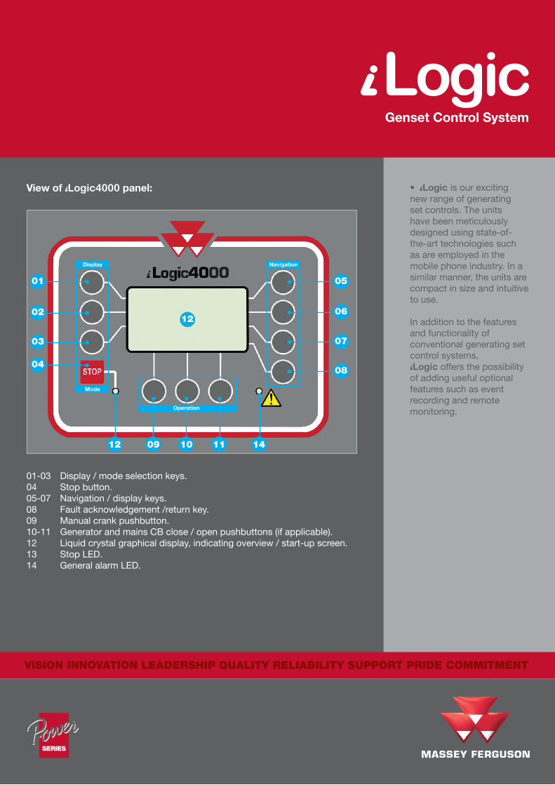
• Logic is our exciting new range of generating set controls. The units have been meticulously designed using state-of-the-art technologies such as are employed in the mobile phone industry. In a similar manner, the units are compact in size and intuitive to use.
In addition to the features and functionality of conventional generating set control systems, Logic offers the possibility
of adding useful optional features such as event recording and remote monitoring.
Genset Control System
VISION INNOVATION LEADERSHIP QUALITY RELIABILITY SUPPORT PRIDE COMMITMENT
01-03 Display / mode selection keys.04 Stop button.05-07 Navigation / display keys.08 Fault acknowledgement /return key.09 Manual crank pushbutton.10-11 Generator and mains CB close / open pushbuttons (if applicable).12 Liquid crystal graphical display, indicating overview / start-up screen.13 Stop LED.14 General alarm LED.
View of Logic4000 panel:
01
02
03
04
05
06
07
08
12
09 10 1112 14
Display Navigation
Mode
Operation
is a worldwide brand of AGCO Corporation.© AGCO Limited. 2008 | 14692/1008/500 | A-English/1008/500
Application
Lo
gic
10
00
Lo
gic
30
00
Lo
gic
40
00
Lo
gic
50
00
Single unit ● ● ● ●
Standby ● ● ● ●
Remote start – ● ● ●
Automatic Mains Failure – – – ●
Display media
LED indication of parameter status ● ● – –
Digital display of measured parameters – ● – –
LCD graphical display (multilingual) – – ● ●
Genset parameter display
AC voltage x 6 (V12, V23, V31, V1N, V2N, V3N) – ● ● ●
AC current x 3 (I1, I2, I3) – ● ● ●
Frequency – ● ● ●
Power factor – – ● ●
Power (kW) – ● ● ●
Power (kVA, kVAr) and Energy (kWh) – – ● ●
Engine coolant temperature – ● ● ●
Engine lube oil pressure – ● ● ●
Battery voltage – ● ● ●
Start attempts – – ● ●
Hours run ● ● ● ●
Tachometer – – ● ●
Mains parameter display
AC voltage x 6 (V12, V23, V31, V1N, V2N, V3N) – – – ●
AC current x 1 (I1) – – – ●
Frequency – – – ●
Power (kVA, kW, kVAr) – – – ●
Operator controls
Configuration via front panel – ● ● ●
Configuration via PC (using DPC cable from – – ● ●
RS232 service interface socket to PC) – – ● ●
Soft keys (with functions that vary depending on application and operation)
– ● ● ●
Multi level access via passwords ● ● ● ●
System control functions
Manual genset starting ● ● ● ●
Remote genset starting – ● ● ●
Automatic genset starting from determination of Mains Failure condition
– – – ●
Start logic for engine (crank, rest and no. of cycles) ● ● ● ●
Stop logic for engine (run on /cool down sequence) ● ● ● ●
Automatic on /off control of heaters, if fitted – ● ● ●
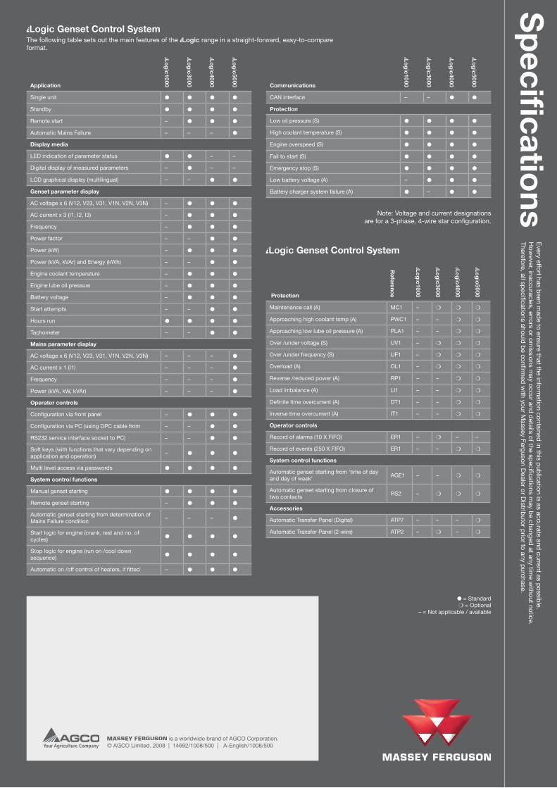
Note: Voltage and current designations are for a 3-phase, 4-wire star configuration.
The following table sets out the main features of the Logic range in a straight-forward, easy-to-compare format.
● = Standard m = Optional
– = Not applicable / available
Logic Genset Control SystemE
very effort has been made to ensure that the inform
ation contained in this publication is as accurate and current as possible. H
owever, inaccuracies, errors or om
issions may occur and details of the specifications m
ay be changed at any time w
ithout notice. Therefore, all specifications should be confirm
ed with your M
assey Ferguson Dealer or D
istributor prior to any purchase.Specifi
cations
Communications
Lo
gic
10
00
Lo
gic
30
00
Lo
gic
40
00
Lo
gic
50
00
CAN interface – – ● ●
Protection
Low oil pressure (S) ● ● ● ●
High coolant temperature (S) ● ● ● ●
Engine overspeed (S) ● ● ● ●
Fail to start (S) ● ● ● ●
Emergency stop (S) ● ● ● ●
Low battery voltage (A) – ● ● ●
Battery charger system failure (A) ● – ● ●
Protection
Reference
Lo
gic
10
00
Lo
gic
30
00
Lo
gic
40
00
Lo
gic
50
00
Maintenance call (A) MC1 – m m m
Approaching high coolant temp (A) PWC1 – – m m
Approaching low lube oil pressure (A) PLA1 – – m m
Over /under voltage (S) UV1 – m m m
Over /under frequency (S) UF1 – m m m
Overload (A) OL1 – m m m
Reverse /reduced power (A) RP1 – – m m
Load imbalance (A) LI1 – – m m
Definite time overcurrent (A) DT1 – – m m
Inverse time overcurrent (A) IT1 – – m m
Operator controls
Record of alarms (10 X FIFO) ER1 – m – –
Record of events (250 X FIFO) ER1 – – m m
System control functions
Automatic genset starting from ‘time of day and day of week’
AGE1 – – m m
Automatic genset starting from closure of two contacts
RS2 – m m m
Accessories
Automatic Transfer Panel (Digital) ATP7 – – – m
Automatic Transfer Panel (2-wire) ATP2 – m – m
Logic Genset Control System