Catalog Everfocus 2012 Catalog-Everfocus-2012 Catalog-Everfocus-2012

Genie XMS Central Management Software Enterprise-Level, Intelligent Analysis, Distributed Connectivity
User’s Manual
Copyright © EverFocus Electronics Corp. Release Date: March, 2017

i
E V E R F O C U S E L E C T R O N I C S C O R P O R A T I O N
Genie XMS Central Management Software
User’s Manual 1995-2017 EverFocus Electronics Corp.
www.everfocus.com.tw
Disclaimer All the images including product pictures or screen shots in this document are for example only. The images may vary depending on the product and software version. Information contained in
this document is subject to change without notice.
Copyright All rights reserved. No part of the contents of this manual may be reproduced or transmitted in any form or by any means without written permission of the EverFocus Electronics Corporation.

ii
TABLE OF CONTENTS
1. Introduction ................................................................................................................. 1
2. Application ................................................................................................................... 2
3. General Operation ....................................................................................................... 3
3.1 Login / Logout .............................................................................................................. 3 3.2 Activate the License ..................................................................................................... 4 3.3 Live View Window ........................................................................................................ 8
3.3.1 eMap Window ................................................................................................. 10 3.3.1.1 Go to eMap Layer ............................................................................... 13 3.3.1.2 Event Pop-Up on eMap ...................................................................... 15 3.3.1.3 Live View Window on eMap .............................................................. 18
3.3.2 Live View Tool Bar ........................................................................................... 19 3.3.3 Device List Setup ............................................................................................. 20
3.3.3.1 Group Settings .................................................................................... 21 3.3.3.2 Editing Device Configurations ............................................................ 23 3.3.3.3 Device Type List .................................................................................. 24 3.3.3.4 Functions on Device List ..................................................................... 25 3.3.3.5 Adding Devices ................................................................................... 26 3.3.3.6 Dynamic System Status Monitoring ................................................... 43 3.3.3.7 Device Maintain ................................................................................. 43
3.3.4 Layout Setting ................................................................................................. 45 3.3.5 Page Sequence ................................................................................................ 48 3.3.6 PTZ Control ...................................................................................................... 51
3.3.6.1 Live View PTZ Control ......................................................................... 51 3.3.6.2 PTZ Control Panel ............................................................................... 52 3.3.6.3 Set Preset ........................................................................................... 54 3.3.6.4 Auto Pan ............................................................................................. 55 3.3.6.5 Set Pattern.......................................................................................... 57 3.3.6.6 Set Tour .............................................................................................. 58 3.3.6.7 Auto Tracking ..................................................................................... 60
3.3.7 Digital Zoom / Fisheye ..................................................................................... 63 3.3.7.1 Digital Zoom ....................................................................................... 63 3.3.7.2 Fisheye ................................................................................................ 64
3.3.8 eZ Tracker ........................................................................................................ 65 3.4 Recording ................................................................................................................... 70
3.4.1 Live View Recording ........................................................................................ 70 3.4.2 Schedule Recording ......................................................................................... 71
iii
3.4.3 Setting up the Recording Path ........................................................................ 74 3.4.4 Auto Backup Recording ................................................................................... 75
3.5 Playback ..................................................................................................................... 77 3.5.1 Remote Playback ............................................................................................. 77
3.5.1.1 Playback Bar ....................................................................................... 78 3.5.1.2 Quick Playback ................................................................................... 82
3.5.2 Local Playback ................................................................................................. 87 3.5.2.1 Remote Archive from the System ...................................................... 87
3.6 Event List .................................................................................................................... 89 3.7 Genie XMS Servers Management .............................................................................. 90
3.7.1 Adding Multiple IP Cameras from a Genie XMS Server to the System ........... 90 3.7.2 Group Setup .................................................................................................... 91 3.7.3 User Privilege Setup ........................................................................................ 94
3.8 Push Notification Function ......................................................................................... 99

Genie XMS Central Management Software
iv
4. Setting ............................................................................................................................. 105
4.1 Device Setting .....................................................................................................................105 4.2 Record & Play .....................................................................................................................106
4.2.1 Built-In Calculator ...........................................................................................................106 4.2.2 Playback .........................................................................................................................106 4.2.3 Holidays ..........................................................................................................................107 4.2.4 Schedule .........................................................................................................................107 4.2.5 Archive............................................................................................................................110
4.3 Event...................................................................................................................................112 4.3.1 Alarm/Event Setting (Device) .........................................................................................112
4.3.1.1 Access Controller ........................................................................................................113 4.3.1.2 DVR .............................................................................................................................115 4.3.1.3 IPCam .........................................................................................................................120 4.3.1.4 NVR .............................................................................................................................123 4.3.1.5 RTSP ............................................................................................................................126
4.3.2 System Event (Server) ....................................................................................................130 4.3.3 Event Setting ..................................................................................................................132 4.3.4 Event Audio Setting ........................................................................................................133
4.4 Geofence Setting ................................................................................................................134 4.4.1 Geofence Schedule Profile .............................................................................................134
4.5 Storage Device ...................................................................................................................139 4.5.1 Disk Information .............................................................................................................139 4.5.2 Storage Device Management .........................................................................................140 4.5.3 iSCSI Setting ....................................................................................................................145
4.6 Network ..............................................................................................................................146 4.6.1 Network Setting .............................................................................................................146 4.6.2 Email ...............................................................................................................................149 4.6.3 DDNS ..............................................................................................................................150 4.6.4 Network Test ..................................................................................................................151
4.7 System Setting ....................................................................................................................152 4.7.1 Time Zone .......................................................................................................................152 4.7.2 Date / Time .....................................................................................................................153 4.7.3 EKB200 ...........................................................................................................................154 4.7.4 Miscellaneous.................................................................................................................156 4.7.5 Customized Title and Icon ..............................................................................................157 4.7.6 License ............................................................................................................................158 4.7.7 Database Backup and Restore .......................................................................................162 4.7.8 Firmware Upgrade .........................................................................................................163 4.7.9 EMX32 ............................................................................................................................164 4.7.10 SNMP ..........................................................................................................................165 4.7.11 eMap Icon Setting ......................................................................................................166 4.7.12 Black/White List .........................................................................................................167
4.8 Failover Setting...................................................................................................................168 4.9 User Setting ........................................................................................................................169

Genie XMS Central Management Software
v
4.9.1 User Time Zone ..............................................................................................................169 4.9.2 Local Save Settings .........................................................................................................170 4.9.3 OSD Setting ....................................................................................................................171 4.9.4 Change Own Password ...................................................................................................172 4.9.5 Language ........................................................................................................................173 4.9.6 Page ................................................................................................................................173
4.10 User Management .............................................................................................................174 4.10.1 User Account ..............................................................................................................174 4.10.2 User Group .................................................................................................................177
4.11 System Information ............................................................................................................180 4.11.1 System ........................................................................................................................180 4.11.2 System Log .................................................................................................................181 4.11.3 Server Status ..............................................................................................................182 4.11.4 Recording Data Report ...............................................................................................183
5. Licensed Functions ........................................................................................................... 185
5.1 Xfleet Management ...........................................................................................................186 5.2 Access Control ....................................................................................................................187
5.2.1 Playback Bar for Access Control .....................................................................................188 5.2.2 Adding Access Control Server to the XMS Server ..........................................................190 5.2.3 Setting up Event Configurations ....................................................................................194

Genie XMS Central Management Software
1
1. Introduction EverFocus Genie XMS is an open system integration platform which is well designed with a scalable and modular architecture that can be easily expanded or integrated with various systems or applications such as POS, LPR, access control and fleet management. Most importantly, Genie XMS can analyze big data and information accumulated from all these systems in order to make prediction, to provide instant response and even to optimize business performance, creating long-term value for clients across various verticals and industries.
Genie XMS also features its strong compatibility and interoperability which allows it to connect all sorts of devices including IP cameras, NVRs, DVRs, mobile DVRs, I/O devices, smart mobile devices and access control products. Therefore, it can be tailored to meet a variety of needs and have a wider range of application. Together with the web-based platform advantage, users can simply access the surveillance system from any remote site just with a web browser, making the surveillance available anywhere and anytime.
Commander 2 ENVR8008
Mobile PadNotebook
Network
EverFocus Genie XMS CMS 1
ONVIF-Conformant 3rd Party IP Camera
EverFocus Devices(IP camera / DVR / NVR / Access Control System)
iOS / Android
Elite3 NVE04GX
Systems and Devices from Other Brands like
LPR, POS, I/O Devices
EverFocus Genie XMS CMS N
Chapter
1

Genie XMS Central Management Software
2
2. Application
The Genie XMS comes with two versions listed as below. The content of this manual contains full functions of the Genie XMS software. Please be noted that the license required functions may not be operated unless the license has been acquired and activated. To activate the license, please refer to 3.2 Activate the License.
• Standard
• Full Function (Standard functions + Access Control + Xfleet)
The content can also be applied to the following EverFocus NVR series.
• Commander 2 Series NVR
• Elite 3 Series NVR
The Genie XMS CMS is designed with an open platform, allowing customization to cater to your needs. Please contact EverFocus if customization is required.
Features:
• Distribution (Server everywhere)
• Full Connection (Connecting peace of mind)
• Customization (Adaptable, Extendable)
• Intelligence (Data management)
Chapter
2

Genie XMS Central Management Software
3
3. General Operation
3.1 Login / Logout 1. To log in the system, open a Web browser, type the IP address of the system in the address
field and press the Enter key on the keyboard, the Welcome window pops up. Follow the instruction steps to update the latest Plugin version. After reloading the webpage, the login window pops up. Type the user ID and password to log in. By default, the user ID is admin and password is 11111111
Note for the first time login:
The Welcome window will only be prompted for the first time login in order to update the system to the latest plugin version.
The Agreement window will only be prompted for the first time login. Click Agree.
If you are using Firefox browser, click Allow when the below blocking message appears, and then refresh the browser.
2. To log out the system, click the Logout button on the upper-right corner of the Live View Window. The system will return to the login window.
Chapter
3

Genie XMS Central Management Software
4
3.2 Activate the License Users can activate the license by an Online or Offline process. Computers connected to the internet can be activated Online while computers without an internet connection should be activated using the Offline process.
To activate the license, on the Live View window, click the Setting button to display the left-side menu bar. Click System Setting and then click License.
Online Activation:
1. Select Online Mode.
2. Enter the basic information in the fields such as Company Name, Email and TEL.
3. Enter the Supported Channel Number of this license that you purchase.
4. Enter the Serial Number you obtained after purchase.
5. Click Activate, and the following window will appear. Please click Confirm and the system will start rebooting.
6. After rebooting, the license is activated.
Genie XMS Central Management Software
5
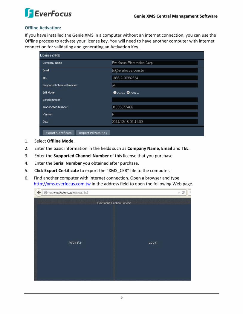
Offline Activation:
If you have installed the Genie XMS in a computer without an internet connection, you can use the Offline process to activate your license key. You will need to have another computer with internet connection for validating and generating an Activation Key.
1. Select Offline Mode.
2. Enter the basic information in the fields such as Company Name, Email and TEL.
3. Enter the Supported Channel Number of this license that you purchase.
4. Enter the Serial Number you obtained after purchase.
5. Click Export Certificate to export the “XMS_CER” file to the computer.
6. Find another computer with internet connection. Open a browser and type http://xms.everfocus.com.tw in the address field to open the following Web page.
Genie XMS Central Management Software
6
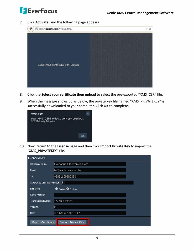
7. Click Activate, and the following page appears.
8. Click the Select your certificate then upload to select the pre-exported “XMS_CER” file.
9. When the message shows up as below, the private key file named “XMS_PRIVATEKEY” is successfully downloaded to your computer. Click OK to complete.
10. Now, return to the License page and then click Import Private Key to import the “XMS_PRIVATEKEY” file.
Genie XMS Central Management Software
7
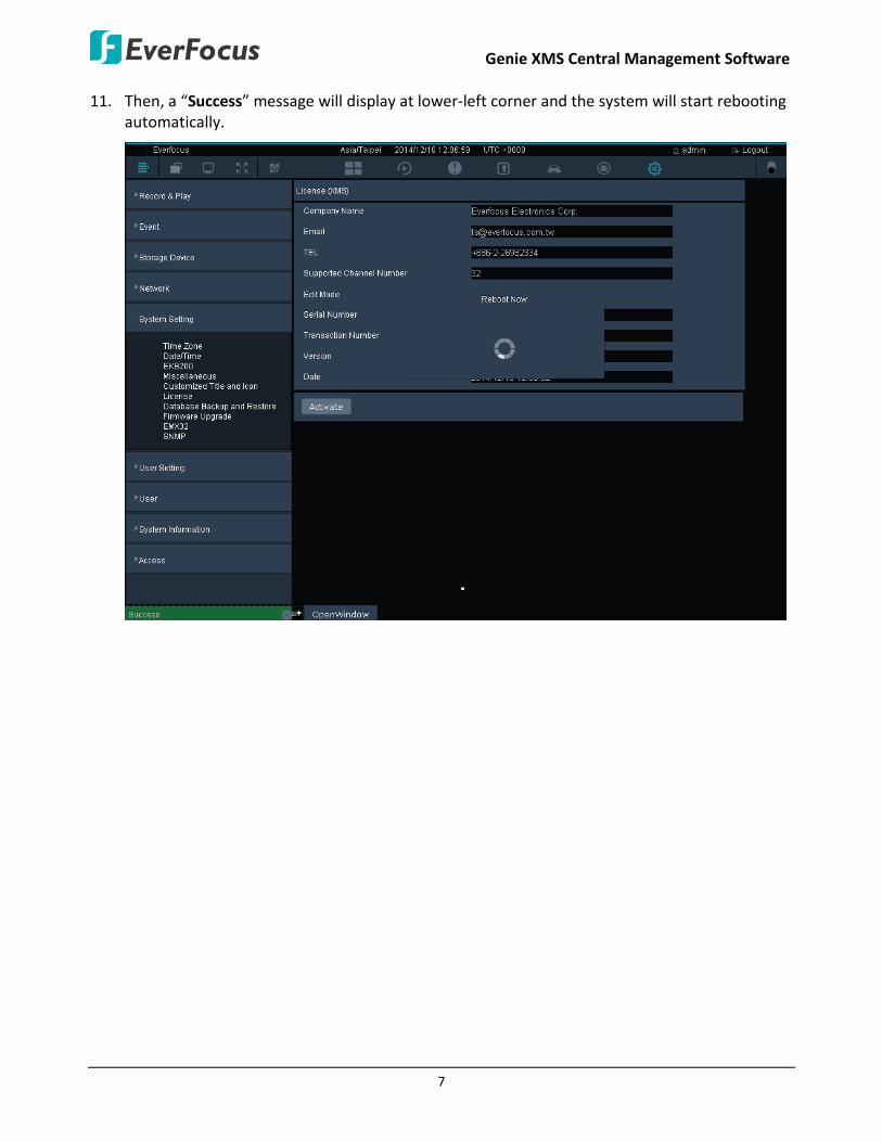
11. Then, a “Success” message will display at lower-left corner and the system will start rebooting automatically.

Genie XMS Central Management Software
8
3.3 Live View Window
25
27
28
26
30
32
34
35
29
31
33
242322211 3 5 7 82 4 6 9
10 12 13 171811
14 162015
19
No
Name Description
1 Tree Menu Click to show / hide the left-side Menu Bar.
2 List Click to display the Device List on the left-side Menu Bar.
3 Ratio Click to switch the ratio of all the live streams between original (source video) and extended (to the layout screen).
4 Group Click to configure the Group settings (see 3.3.3.1 Group Settings).
5 OSD Display Mode Click to show / hide the information of device name and time.
6 eMap Click to enter the eMap setup page (see 3.3.1 eMap Window).
7 Toggle Full Screen Click to display the Matrix Live View in full screen.
8 Option Click to pin the Live View Tool Bar on the Live View screen. See 3.3.2 Live View Tool Bar for more details.
9 Expand / Collapse Click to expand or collapse the Device List.
10 Live View Click to display the Matrix Live View.
11 Page Indicates the current layout of the live view.
12 Playback Click to enter the playback page for multi-channel playback (see 3.5 Playback).

Genie XMS Central Management Software
9
13 Vehicle This function is license required. Click to enter the Xfleet Management page (see 5.1 Xfleet Management).
14 Event List Click to enter the Event List setup page (see 3.6 Event List).
15 Close Stream Click to disconnect the live streams.
16 Access List This function is license required. Click to enter the Access Control setup page (see 5.2 Access Control).
17 Backup This function is license required. Click to enter the Xfleet Backup page (see 5.1 Xfleet Management).
18 Sub Window
Click to open a sub window for displaying the current matrix live view on additional monitor. The number of sub window is unlimited. The sub window live view depends on the current matrix live view displayed on the Genie XMS.
19 Setting Click to enter the Settings page (see 4. Setting).
20 EMX32 Click to display the Matrix Live View on the monitor of EMX32 (see 4.5.9 EMX32).
21 Matrix Live View Displays the live view streams in matrix.
22 Save Click to Add or Update the current live layout as a Page in the Page List (see 3.3.4 Layout Setting).
23 Logout Click to log out the system.
24 Theme Switch Click to switch the theme between the dark and light.
25 Device Click to display the Device List on the left-side menu (see 3.3.3 Device List Setup).Click to switch the theme between the dark and light.
26 Vehicle This function is license required. Click to display the Xfleet Vehicle List (see 5.1 Xfleet Management).
27 Search Column Type in the column to search the Device Name from the list. Click All to display all devices.
28 Device List Displays all the types of devices connected to the system (see 3.3.3.4 Functions on Device List).
29 Layout Detail Click to enter the Layout Design page. You can further create or modify the personal layout design (see 3.3.4 Layout Setting).
30 Layout Click to enter the layout page (see 3.3.4 Layout Setting).
31 PTZ Detail Click to enter the PTZ setup page (see 3.3.6 PTZ Control).
32 PTZ Control Click to display the PTZ Control panel (see 3.3.6 PTZ Control).
33 Page Detail Click to enter the Page setup page (see 3.3.5 Page Sequence).
34 Page Click to display the Page List (see 3.3.5 Page Sequence).
35 Digital Zoom / Fisheye
Click to enter the Digital Zoom / Fisheye operation page (see 3.3.7 Digital Zoom / Fisheye).
Genie XMS Central Management Software
10
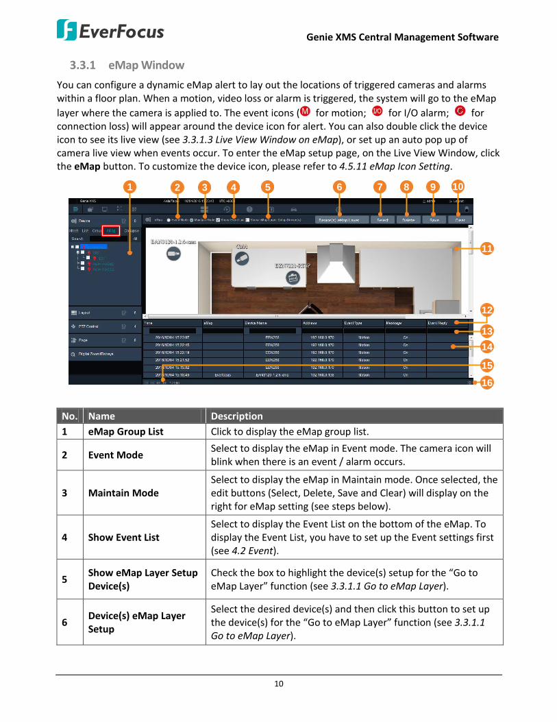
3.3.1 eMap Window
You can configure a dynamic eMap alert to lay out the locations of triggered cameras and alarms within a floor plan. When a motion, video loss or alarm is triggered, the system will go to the eMap layer where the camera is applied to. The event icons ( for motion; for I/O alarm; for connection loss) will appear around the device icon for alert. You can also double click the device icon to see its live view (see 3.3.1.3 Live View Window on eMap), or set up an auto pop up of camera live view when events occur. To enter the eMap setup page, on the Live View Window, click the eMap button. To customize the device icon, please refer to 4.5.11 eMap Icon Setting.
1 6 7 8 92 3 4 5 10
14
1516
12
13
11
No. Name Description 1 eMap Group List Click to display the eMap group list.
2 Event Mode Select to display the eMap in Event mode. The camera icon will blink when there is an event / alarm occurs.
3 Maintain Mode Select to display the eMap in Maintain mode. Once selected, the edit buttons (Select, Delete, Save and Clear) will display on the right for eMap setting (see steps below).
4 Show Event List Select to display the Event List on the bottom of the eMap. To display the Event List, you have to set up the Event settings first (see 4.2 Event).
5 Show eMap Layer Setup Device(s)
Check the box to highlight the device(s) setup for the “Go to eMap Layer” function (see 3.3.1.1 Go to eMap Layer).
6 Device(s) eMap Layer Setup
Select the desired device(s) and then click this button to set up the device(s) for the “Go to eMap Layer” function (see 3.3.1.1 Go to eMap Layer).

Genie XMS Central Management Software
11
7 Select Click to select an eMap picture (PNG, JPG, JPEG, GIF, TIFF) from your computer.
8 Delete Select a camera on the eMap and then click the Delete button to delete the camera.
9 Save Click to save the settings. 10 Clear Click to remove all the cameras on the eMap. 11 eMap Display Window Displays the eMap Layer. 12 Sort Column Click to sort the data in the column. 13 Search Column Type in text to search the specific data from the column. 14 Event List Displays the triggered events. 15 Turn Page Icons Click to turn to the next / previous / first / last page. 16 Show List Number Click the icon to display the number of events on a page.
To setup an eMap:
1. On the Live View Window, click eMap, click the add node button to add a node. You can add multiple nodes and using your mouse to drag and drop the nodes for making eMap groups. To edit node name, click the rename button . To delete a node, click the remove button .
2. Click the Select button to select a floor plan image from your computer.
Genie XMS Central Management Software
12
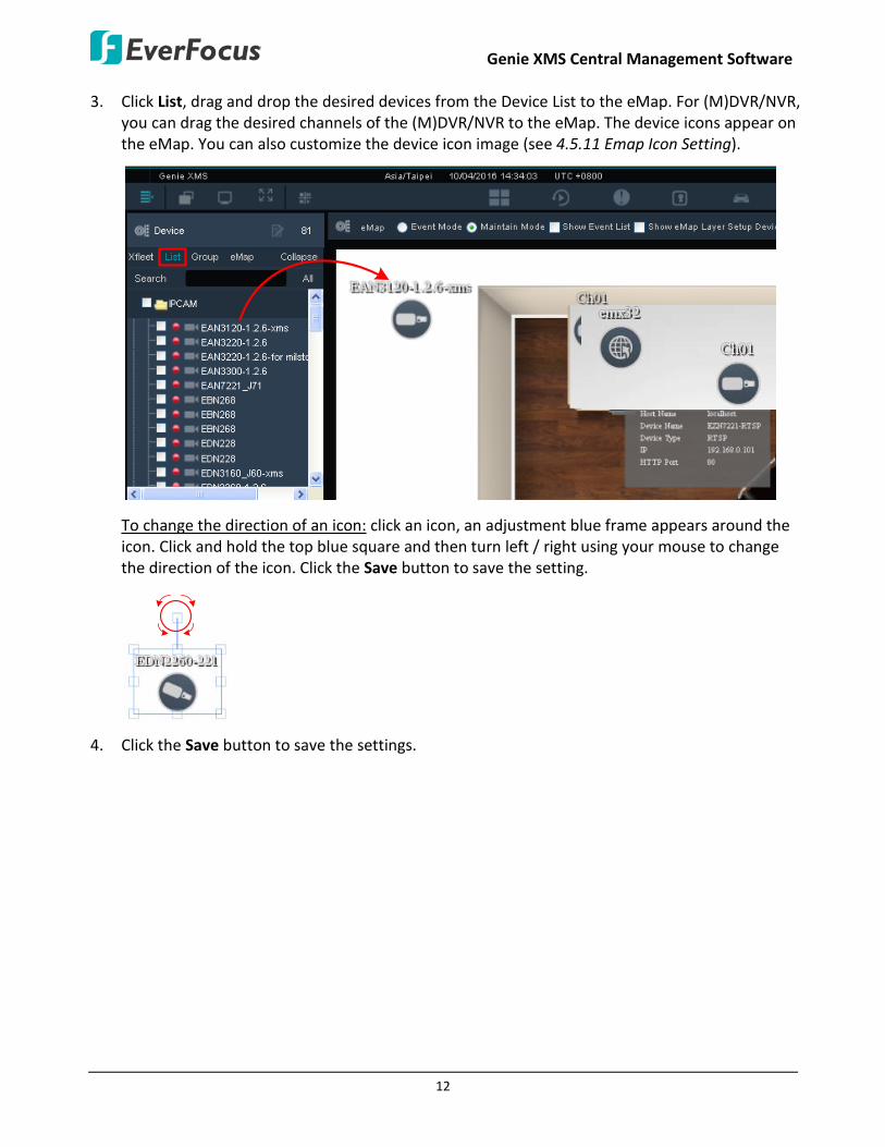
3. Click List, drag and drop the desired devices from the Device List to the eMap. For (M)DVR/NVR, you can drag the desired channels of the (M)DVR/NVR to the eMap. The device icons appear on the eMap. You can also customize the device icon image (see 4.5.11 Emap Icon Setting).
To change the direction of an icon: click an icon, an adjustment blue frame appears around the icon. Click and hold the top blue square and then turn left / right using your mouse to change the direction of the icon. Click the Save button to save the setting.
4. Click the Save button to save the settings.

Genie XMS Central Management Software
13
3.3.1.1 Go to eMap Layer
When an event occurs, the system will go to the eMap layer where the camera is applied to; and the event icon ( for motion; for I/O alarm; for connection loss) will appear around the device icon. For this function to work, you have to set up events for the desired cameras (devices) first (see 4.2 Event).
To enable this function (here we use IP camera Motion Detection triggered on eMap for example):
1. On the Live View Window, click Setting > Event > Alarm/Event Setting (Device). Select IPCam from the device list and Motion from the event type.
2. To apply the Go to eMap Layer function to the desired cameras, check the Enable column of the device and then check the Go to eMap Layer column.
3. To activate the Motion Detection function:
a. Click the Edit Motion Grid button to bring up the Edit Motion Grid window. You can only configure one motion detection zone for each IP camera.

Genie XMS Central Management Software
14
b. Select an IP camera by checking the box on the list. You can also select multiple IP cameras to apply the same motion grid setting to the selected IP cameras.
c. On the Edit Motion Grid window, click the Apply to All button to apply the motion detection function to the entire screen. You can also set up a motion area by using your mouse to drag an area.
d. Click the Sensitivity drop-down list to select the motion sensitivity for the motion area.
e. Click the Apply button to save the settings
4. Click the Apply button to save the settings.
5. Go back to the eMap Window, when an event occurs, the system will go to the eMap layer where the camera is applied to.
6. If you apply one camera to multiple eMap layers, you can assign the XMS server to go to the specific eMap layer applied with this camera.
a. Select an eMap layer from the eMap Group List.
b. Click the device icon on the eMap Display Window and then click the Device(s) eMap Layer Setup button. A Success message will appear on the bottom-left to indicate the setting is done successfully. You can follow this step to apply this function to multiple devices.
c. Check the Show eMap Layer Setup Device(s) box will highlight the devices applied with this function.
7. To set up the duration time for the Go to eMap Layer, see 4.2.3 Event Setting.
Genie XMS Central Management Software
15
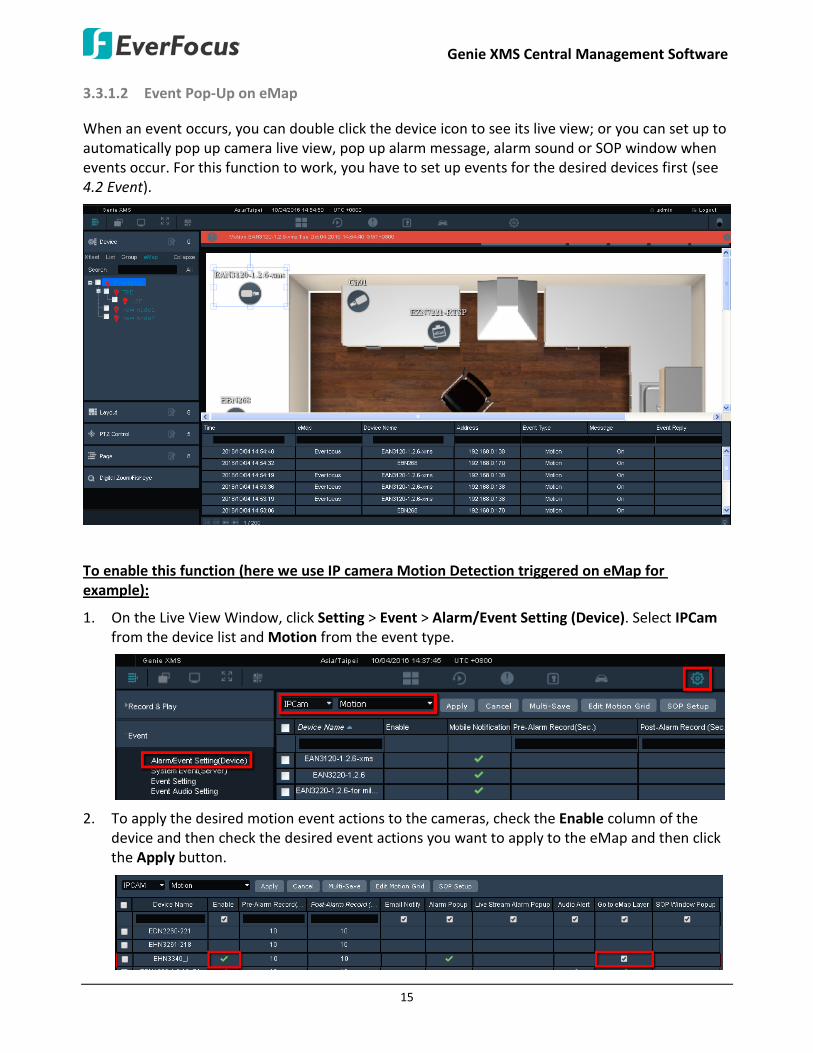
3.3.1.2 Event Pop-Up on eMap
When an event occurs, you can double click the device icon to see its live view; or you can set up to automatically pop up camera live view, pop up alarm message, alarm sound or SOP window when events occur. For this function to work, you have to set up events for the desired devices first (see 4.2 Event).
To enable this function (here we use IP camera Motion Detection triggered on eMap for example):
1. On the Live View Window, click Setting > Event > Alarm/Event Setting (Device). Select IPCam from the device list and Motion from the event type.
2. To apply the desired motion event actions to the cameras, check the Enable column of the device and then check the desired event actions you want to apply to the eMap and then click the Apply button.

Genie XMS Central Management Software
16
You can also click the Multi-Save button to apply the selected event notifications for all the devices on this page. Check the device boxes first and then click the Multi-Save button.
Pre-Alarm Record (Sec.): Set up the duration for the buffer in second. This will determine the amount of footage (length of time) before the event trigger moment that will be included in an event video recording.
Post-Alarm Record (Sec.): Set up the duration for the buffer in second. This will determine the amount of footage (length of time) after the event trigger moment that will be included in an event video recording.
Email Notify: An email notification will send to the pre-configured receiver (see 4.4.2 Email).
Alarm Popup: An alarm text will pop up on the top window.
Live Stream Alarm Popup: A live view window will pop up.
Audio Alert: An alarm sound will be activated for alert notification. To set up an alarm sound, please refer to 4.2.4 Event Audio Setting.
Go to eMap Layer: The system will go to the eMap layer where the triggered camera is applied to (see 3.3.1.1 Go to eMap Layer).
SOP Window Popup: An SOP window will pop up displaying the event procedures to take. When this window pops up, you can check the procedures and enter the information of what actions you have done in the blank. Click the Save button to save the information. The information will be displayed on the Event List (see 3.6 Event List). For this function to work, you have to click the SOP Setup button to edit an event procedure in advance.

Genie XMS Central Management Software
17
Event List (image below)
You can configure the dwell time for each event action and the number of SOP Window, please refer to 4.2.3 Event Setting for more details.
3. To activate the Motion Detection function:
a. Click the Edit Motion Grid button to call up the Edit Motion Grid window. You can only configure one motion detection zone for each IP camera.
b. Select an IP camera by checking the box on the list. You can also select multiple IP cameras to apply the same motion grid setting to the selected IP cameras.
c. On the Edit Motion Grid window, click the Apply to All button to apply the motion detection function to the entire screen. You can also set up a motion area by using your mouse to drag an area.
d. Click the Sensitivity drop-down list to select the motion sensitivity for the motion area.
e. Click the Apply button to save the settings
4. Click the Apply button to save the settings.
5. Go back to the eMap Window, when an event occurs, the configured event actions will pop up.
Genie XMS Central Management Software
18
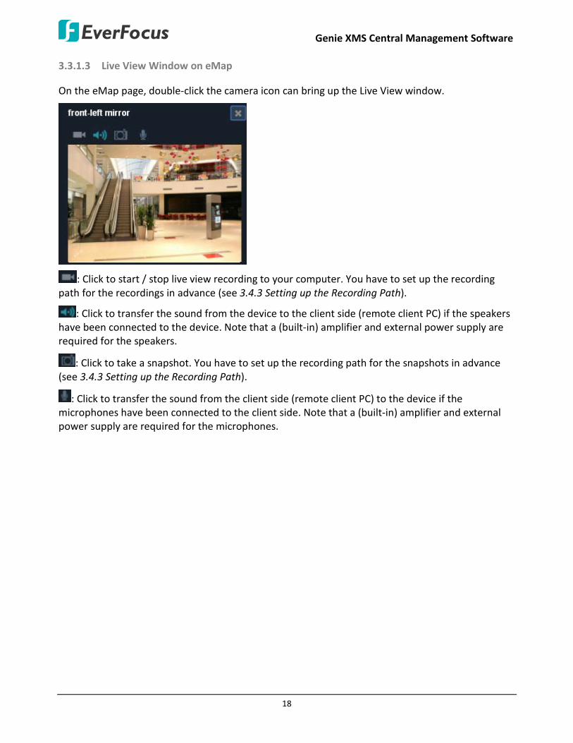
3.3.1.3 Live View Window on eMap
On the eMap page, double-click the camera icon can bring up the Live View window.
: Click to start / stop live view recording to your computer. You have to set up the recording path for the recordings in advance (see 3.4.3 Setting up the Recording Path).
: Click to transfer the sound from the device to the client side (remote client PC) if the speakers have been connected to the device. Note that a (built-in) amplifier and external power supply are required for the speakers.
: Click to take a snapshot. You have to set up the recording path for the snapshots in advance (see 3.4.3 Setting up the Recording Path).
: Click to transfer the sound from the client side (remote client PC) to the device if the microphones have been connected to the client side. Note that a (built-in) amplifier and external power supply are required for the microphones.
Genie XMS Central Management Software
19
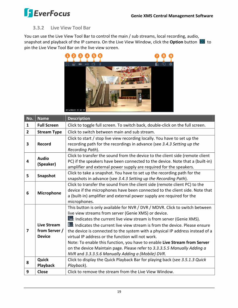
3.3.2 Live View Tool Bar
You can use the Live View Tool Bar to control the main / sub streams, local recording, audio, snapshot and playback of the IP camera. On the Live View Window, click the Option button to pin the Live View Tool Bar on the live view screen.
1 2 3 4 5 8 976
No. Name Description
1 Full Screen Click to toggle full screen. To switch back, double-click on the full screen.
2 Stream Type Click to switch between main and sub stream.
3 Record Click to start / stop live view recording locally. You have to set up the recording path for the recordings in advance (see 3.4.3 Setting up the Recording Path).
4 Audio (Speaker)
Click to transfer the sound from the device to the client side (remote client PC) if the speakers have been connected to the device. Note that a (built-in) amplifier and external power supply are required for the speakers.
5 Snapshot Click to take a snapshot. You have to set up the recording path for the snapshots in advance (see 3.4.3 Setting up the Recording Path).
6 Microphone
Click to transfer the sound from the client side (remote client PC) to the device if the microphones have been connected to the client side. Note that a (built-in) amplifier and external power supply are required for the microphones.
7 Live Stream from Server / Device
This button is only available for NVR / DVR / MDVR. Click to switch between live view streams from server (Genie XMS) or device.
: Indicates the current live view stream is from server (Genie XMS). : Indicates the current live view stream is from the device. Please ensure
the device is connected to the system with a physical IP address instead of a virtual IP address or the function will not work. Note: To enable this function, you have to enable Live Stream from Server on the device Maintain page. Please refer to 3.3.3.5.5 Manually Adding a NVR and 3.3.3.5.6 Manually Adding a (Mobile) DVR.
8 Quick Playback
Click to display the Quick Playback Bar for playing back (see 3.5.1.3 Quick Playback).
9 Close Click to remove the stream from the Live View Window.

Genie XMS Central Management Software
20
3.3.3 Device List Setup Page
You can add, configure and manage the device list using this page. On the Live View Window, click
Setting to bring up the left-side setting menu. Click Device in the Device Setting field, the Device List Setup page appears on the right window.
5
14
1 32 4 109 116
1312
7 8
No
Name Description
1 Group / List Click to switch between Group view and List view for the Device List. You can also setup the Group settings (see 3.3.3.1 Group Settings).
2 Edit / View Click to switch between Edit and View mode for the Device List. For editing the device configurations, see 3.3.3.2 Editing Device Configurations.
3 Export Click to export the Device List file (.csv).
4 Load Template Click to download the Device List Template (.csv).
5 Total Display the current number of the connected devices.
6 Device Type List Click the drop down list and select the desired device type (see 3.3.3.3 Device Type List).
7 Import Click to import the Device List file (.csv).
8 Refresh Click to refresh the page.
9 Close Click to close the Device List Setup page and return to the Setting page.
10 Delete Select the desired devices on the list and click the Delete button to remove the devices from the Device List.
11 Add Click to enter the Maintain page for adding devices. For more details on adding devices, see 3.3.3.5 Adding Devices.
12 Sort Column Click to sort the data in the column.
13 Search Column Type in text to search the specific data from the column.
14 Device Indicator The Device Indicator indicates the status of the devices (see 3.3.3.4 Functions on Device List).

Genie XMS Central Management Software
21
3.3.3.1 Group Settings
You can configure the Device List to be displayed in group view.
1. On the Live View Window, click Setting to bring up the left-side setting menu. Click Device in the Device Setting field, the Device List Setup page appears on the right window.
2. On the Device List Setup page, click the Group button.
3. Click the Group folder on the Group List, the modification icons appears.
4. Click the add node button and enter a name to add a node.

Genie XMS Central Management Software
22
5. Click the List button, drag a device from the Device List and drop it to the created group. You can drag multiple devices to a single group.
6. If you want to change the device to another group, drag the device and drop it to the desired group. You can also drag and drop the group to organize the group layer.
Move your mouse cursor over the device on the Group List can display the group/device info or double-click the device to enter its Web interface for remote configuration.
7. Click the Save button to save the settings.

Genie XMS Central Management Software
23
3.3.3.2 Editing Device Configurations
You can edit the general device setting including Device Name, IP, HTTP port or enable / disable the
device to the system. On the Live View Window, click Setting to bring up the left-side setting menu. Click Device in the Device Setting field, the Device List Setup page appears on the right window.
On the Device List Setup page, click the Edit / View button , click the column you want to configure and input the setting. Click the Update button to save the settings.
You can also edit the detail device configurations. On the Live View Window, click Setting to bring up the left-side setting menu. Click Device in the Device Setting field, the Device List Setup page appears on the right window.
On the Device List Setup page, double click on a device, the Maintain page appears (see 3.3.3.5
Adding Devices). Configure the settings and then click the Save button .

Genie XMS Central Management Software
24
3.3.3.3 Device Type List
You can add devices, image, message or even a Website to the system. On the Device List Setup page, click the Device Type List drop-down list to select a device type.
No. Name Description 1 RTSP RTSP streaming URL.
2 Vehicle Vehicle contains multiple mobile DVRs.
3 IO All kinds of I/O devices.
4 IPCAM IP camera.
5 NVR EverFocus NVR.
6 DVR EverFocus DVR and mobile DVR.
7 XMS EverFocus XMS server.
8 Web Web URL.
9 Message Display message for Text or Marquee mode.
10 Image Picture (PNG, JPG, JPEG, GIF, TIF).
11 Access Access controllers or readers.
12 Access Server ENS2000 Access management software.
Genie XMS Central Management Software
25
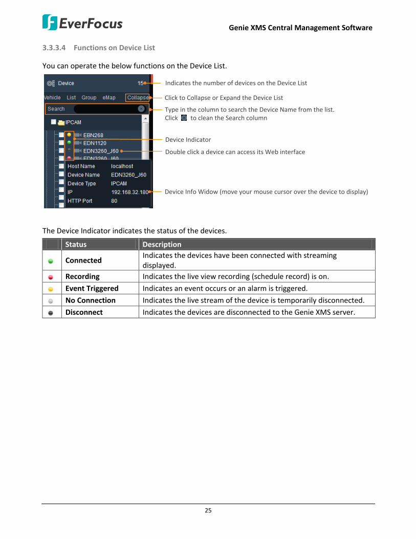
3.3.3.4 Functions on Device List
You can operate the below functions on the Device List.
Click to Collapse or Expand the Device List
Type in the column to search the Device Name from the list. Click to clean the Search column
Device Info Widow (move your mouse cursor over the device to display)
Device Indicator
Double click a device can access its Web interface
Indicates the number of devices on the Device List
The Device Indicator indicates the status of the devices.
Status Description
Connected Indicates the devices have been connected with streaming displayed.
Recording Indicates the live view recording (schedule record) is on.
Event Triggered Indicates an event occurs or an alarm is triggered.
No Connection Indicates the live stream of the device is temporarily disconnected.
Disconnect Indicates the devices are disconnected to the Genie XMS server.
Genie XMS Central Management Software
26
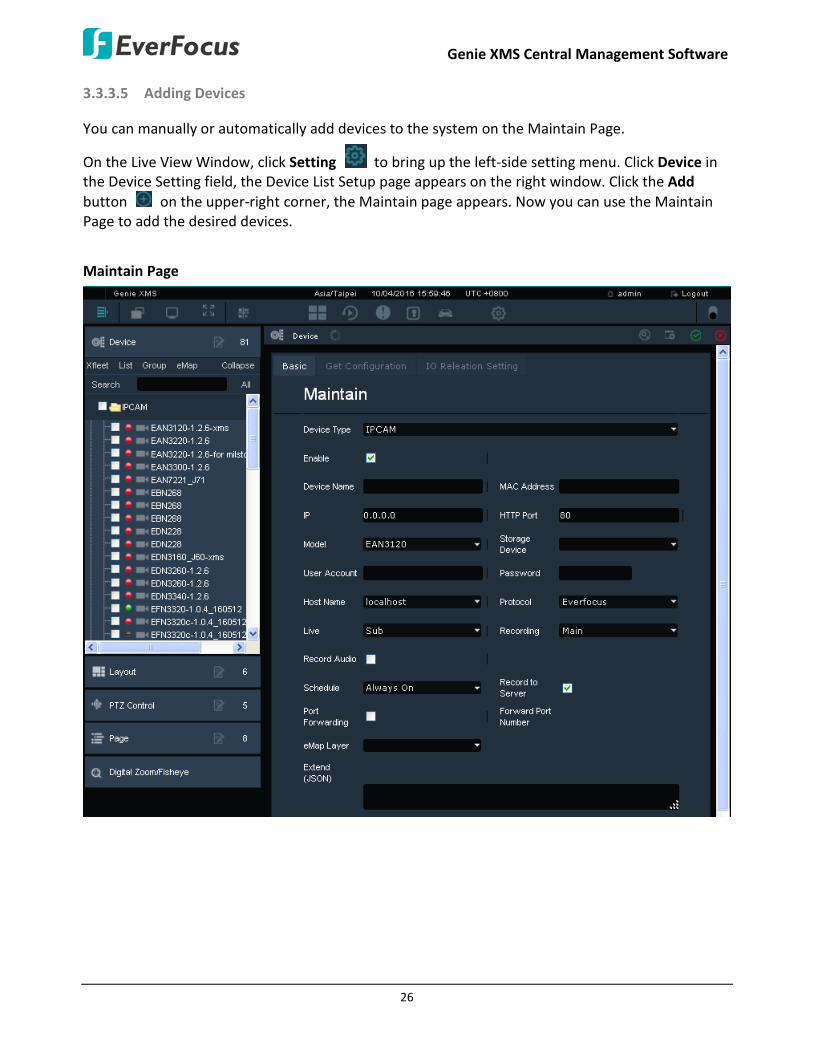
3.3.3.5 Adding Devices
You can manually or automatically add devices to the system on the Maintain Page.
On the Live View Window, click Setting to bring up the left-side setting menu. Click Device in the Device Setting field, the Device List Setup page appears on the right window. Click the Add button on the upper-right corner, the Maintain page appears. Now you can use the Maintain Page to add the desired devices.
Maintain Page
Genie XMS Central Management Software
27
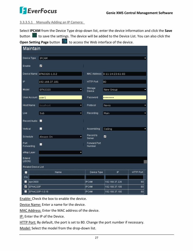
3.3.3.5.1 Manually Adding an IP Camera:
Select IPCAM from the Device Type drop-down list, enter the device information and click the Save
button to save the settings. The device will be added to the Device List. You can also click the
Open Setting Page button to access the Web interface of the device.
Enable: Check the box to enable the device.
Device Name: Enter a name for the device.
MAC Address: Enter the MAC address of the device.
IP: Enter the IP of the Device.
HTTP Port: By default, the port is set to 80. Change the port number if necessary.
Model: Select the model from the drop-down list.

Genie XMS Central Management Software
28
Storage Device: Select a storage device for the schedule recordings. Only the device assigned with a storage device can enable the Schedule Recording function. To setup the storage device, please see To create a new group in 4.3.2 Storage Device Management.
Note: If both of the “IP camera / RTSP device schedule recording” and “DVR / NVR auto backup” functions have been enabled on your Genie XMS server, please assign different Storage Device group to IP camera / RTSP device and DVR / NVR. For example, assign Storage Device A to IP camera and Storage Device B to DVR.
User Account: Enter the user ID of the device.
Password: Enter the password of the device.
Host Name: Select a host from the drop-down list.
Protocol: Select a protocol from the drop-down list.
Live: Select Main or Sub for live view displaying.
Recording: Select Main or Sub for the recording.
Record Audio: Check the box to record the audio.
Assembling: This is only available for Fisheye camera. Select a mounting type of the fisheye camera.
Schedule: Select Always On / Always Off to enable / disable the Schedule recording function. You have to set up a schedule first (see 4.1.4 Schedule).
Record to Server: Check the box to enable schedule recording from the device to the Genie XMS server (see 3.4.2 Schedule Recording).
Port Forwarding: Check the box and then click the Save button to enable the Port Forwarding function. The port number assigned by the XMS server will be displayed in the Forward Port Number field. This function is useful if you want to remotely access XMS server and view the streams or remotely access the device live view from outside of the LAN via the internet (WAN). For this function to work, you have to configure the network setting in advance (see 4.4.1 Network Setting). To remotely access the device live view through WAN, simply type the IP address appended with forwarded port number (for example http://118.122.53.106:20003) in the address field of a browser.
Forward Port Number: After enabling the Port Forwarding function and then click the Save button
, the port number assigned by the XMS server will be displayed in this field.
eMap Layer: Select an eMap layer to apply this device to. This eMap layer will be applied with the Go to eMap Layer function when event occurs (see 3.3.1.1 Go to eMap Layer).
Related Device List: For certain functions, such as eZ Tracker (see 3.3.8 eZ Tracker), it’s required to establish the connection among devices, and the related devices will be listed here.

Genie XMS Central Management Software
29
3.3.3.5.2 Manually Adding an RTSP Device:
Select RTSP from the Device Type drop-down list, enter the device information and click the Save
button to save the settings. The device will be added to the Device List.
Enable: Check the box to enable the device.
Device Name: Enter a name for the device.
IP: Enter the IP address of the device.
URL Path (Main Stream): Enter the main stream RTSP URL format of the Device.
Note: EverFocus device RTSP URL formats are as below:
IP Cameras DVR/NVR
Main Stream Streaming/channels/0
3GPP/[channel (0~N-1)] *Where “0” is for channel 1; “1” is for channel, and so on. “N” is the channel number of the device.
Sub Stream Streaming/channels/1
3GPP/[channel N ~ ] *Where “N” is the channel number of the device. If you are using a 4-ch device, enter “4” for the sub stream of channel 1; “5” for the sub stream of channel 2; “6” for the sub stream of channel 3; and so on.
Genie XMS Central Management Software
30
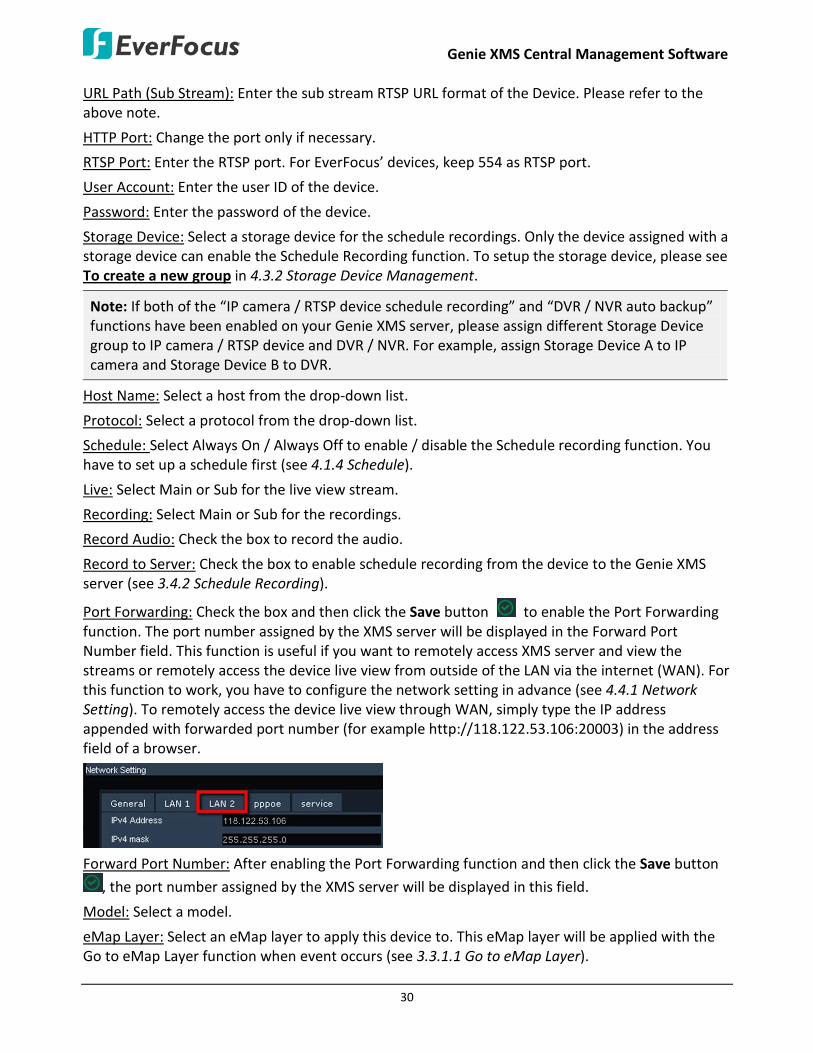
URL Path (Sub Stream): Enter the sub stream RTSP URL format of the Device. Please refer to the above note.
HTTP Port: Change the port only if necessary.
RTSP Port: Enter the RTSP port. For EverFocus’ devices, keep 554 as RTSP port.
User Account: Enter the user ID of the device.
Password: Enter the password of the device.
Storage Device: Select a storage device for the schedule recordings. Only the device assigned with a storage device can enable the Schedule Recording function. To setup the storage device, please see To create a new group in 4.3.2 Storage Device Management.
Note: If both of the “IP camera / RTSP device schedule recording” and “DVR / NVR auto backup” functions have been enabled on your Genie XMS server, please assign different Storage Device group to IP camera / RTSP device and DVR / NVR. For example, assign Storage Device A to IP camera and Storage Device B to DVR.
Host Name: Select a host from the drop-down list.
Protocol: Select a protocol from the drop-down list.
Schedule: Select Always On / Always Off to enable / disable the Schedule recording function. You have to set up a schedule first (see 4.1.4 Schedule).
Live: Select Main or Sub for the live view stream.
Recording: Select Main or Sub for the recordings.
Record Audio: Check the box to record the audio.
Record to Server: Check the box to enable schedule recording from the device to the Genie XMS server (see 3.4.2 Schedule Recording).
Port Forwarding: Check the box and then click the Save button to enable the Port Forwarding function. The port number assigned by the XMS server will be displayed in the Forward Port Number field. This function is useful if you want to remotely access XMS server and view the streams or remotely access the device live view from outside of the LAN via the internet (WAN). For this function to work, you have to configure the network setting in advance (see 4.4.1 Network Setting). To remotely access the device live view through WAN, simply type the IP address appended with forwarded port number (for example http://118.122.53.106:20003) in the address field of a browser.
Forward Port Number: After enabling the Port Forwarding function and then click the Save button
, the port number assigned by the XMS server will be displayed in this field.
Model: Select a model.
eMap Layer: Select an eMap layer to apply this device to. This eMap layer will be applied with the Go to eMap Layer function when event occurs (see 3.3.1.1 Go to eMap Layer).
Genie XMS Central Management Software
31
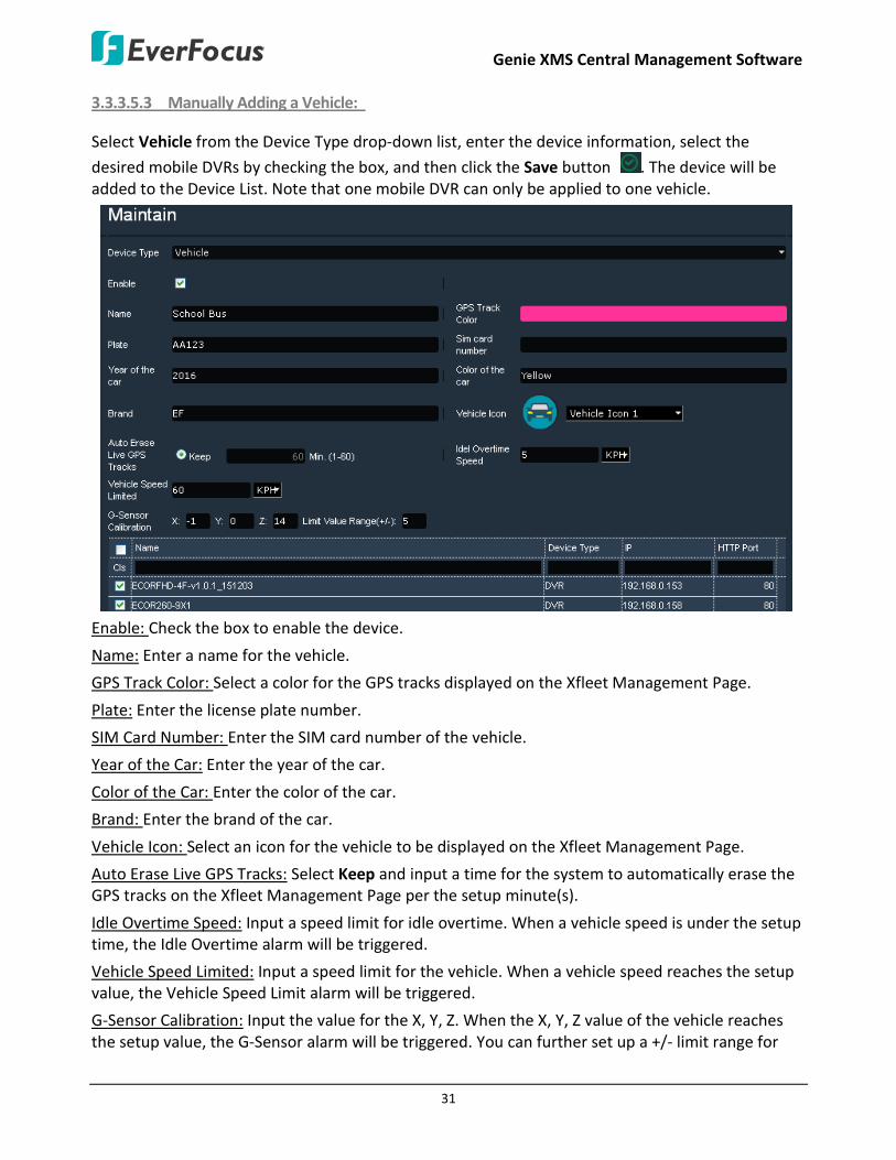
3.3.3.5.3 Manually Adding a Vehicle:
Select Vehicle from the Device Type drop-down list, enter the device information, select the
desired mobile DVRs by checking the box, and then click the Save button . The device will be added to the Device List. Note that one mobile DVR can only be applied to one vehicle.
Enable: Check the box to enable the device.
Name: Enter a name for the vehicle.
GPS Track Color: Select a color for the GPS tracks displayed on the Xfleet Management Page.
Plate: Enter the license plate number.
SIM Card Number: Enter the SIM card number of the vehicle.
Year of the Car: Enter the year of the car.
Color of the Car: Enter the color of the car.
Brand: Enter the brand of the car.
Vehicle Icon: Select an icon for the vehicle to be displayed on the Xfleet Management Page.
Auto Erase Live GPS Tracks: Select Keep and input a time for the system to automatically erase the GPS tracks on the Xfleet Management Page per the setup minute(s).
Idle Overtime Speed: Input a speed limit for idle overtime. When a vehicle speed is under the setup time, the Idle Overtime alarm will be triggered.
Vehicle Speed Limited: Input a speed limit for the vehicle. When a vehicle speed reaches the setup value, the Vehicle Speed Limit alarm will be triggered.
G-Sensor Calibration: Input the value for the X, Y, Z. When the X, Y, Z value of the vehicle reaches the setup value, the G-Sensor alarm will be triggered. You can further set up a +/- limit range for

Genie XMS Central Management Software
32
the X, Y, Z value. For example, if you input 5 for X and 1 for Limit Value Range (+/-), when X value reaches 6 or 4, the G-Sensor alarm will be triggered.
Device List: Check the desired devices from the below list to be added to this Vehicle. To display MDVR list, you have to add MDVR to the system first. Please refer to 3.3.3.5.6 Manually Adding a (Mobile) DVR.
3.3.3.5.4 Manually Adding a NVR:
Select NVR from the Device Type drop-down list, enter the device information, select the desired
channels of the device, and then click the Save button to save the settings. The device will be
added to the Device List. You can also click the Open Setting Page button to access the Web interface of the device.

Genie XMS Central Management Software
33
Enable: Check the box to enable the device.
Device Name: Enter a name for the device.
IP: Enter the IP of the Device.
HTTP Port: By default, the port is set to 80. Change the port number if necessary.
Model: Select the model from the drop-down list.
Storage Device: Select a storage device for the auto backup function. To setup the storage device, please see To create a new group in 4.3.2 Storage Device Management.
Note: If both of the “IP camera / RTSP device schedule recording” and “DVR / NVR auto backup” functions have been enabled on your Genie XMS server, please assign different Storage Device group to IP camera / RTSP device and DVR / NVR. For example, assign Storage Device A to IP camera and Storage Device B to DVR.
User Account: Enter the user ID of the device.
Password: Enter the password of the device.
Live: Select Main or Sub for live view displaying.
Recording: Select Main or Sub for the recording.
Network ID: Enter a 10-digit ID for network identification.
Backup to Server: Check the box to enable the Auto Backup Recording function (see 3.4.4 Auto Backup Recording).
Note: To archive the recordings from DVR, NVR and Mobile DVR in AVI/MP4 format, the Backup to Server function must be checked on the device Maintain page. If the option is unchecked, the recordings will be archived in AVR format (directly archived from the device HDD), and you have to use EverFocus’ players such as EFPlayer or EF-Reader to play back the recordings.
Port Forwarding: Check the box and then click the Save button to enable the Port Forwarding function. The port number assigned by the XMS server will be displayed in the Forward Port Number field. This function is useful if you want to remotely access XMS server and view the streams or remotely access the device live view from outside of the LAN via the internet (WAN). For this function to work, you have to configure the network setting in advance (see 4.4.1 Network Setting). To remotely access the device live view through WAN, simply type the IP address appended with forwarded port number (for example http://118.122.53.106:20003) in the address field of a browser.
Forward Port Number: After enabling the Port Forwarding function and then click the Save button
, the port number assigned by the XMS server will be displayed in this field.
Genie XMS Central Management Software
34
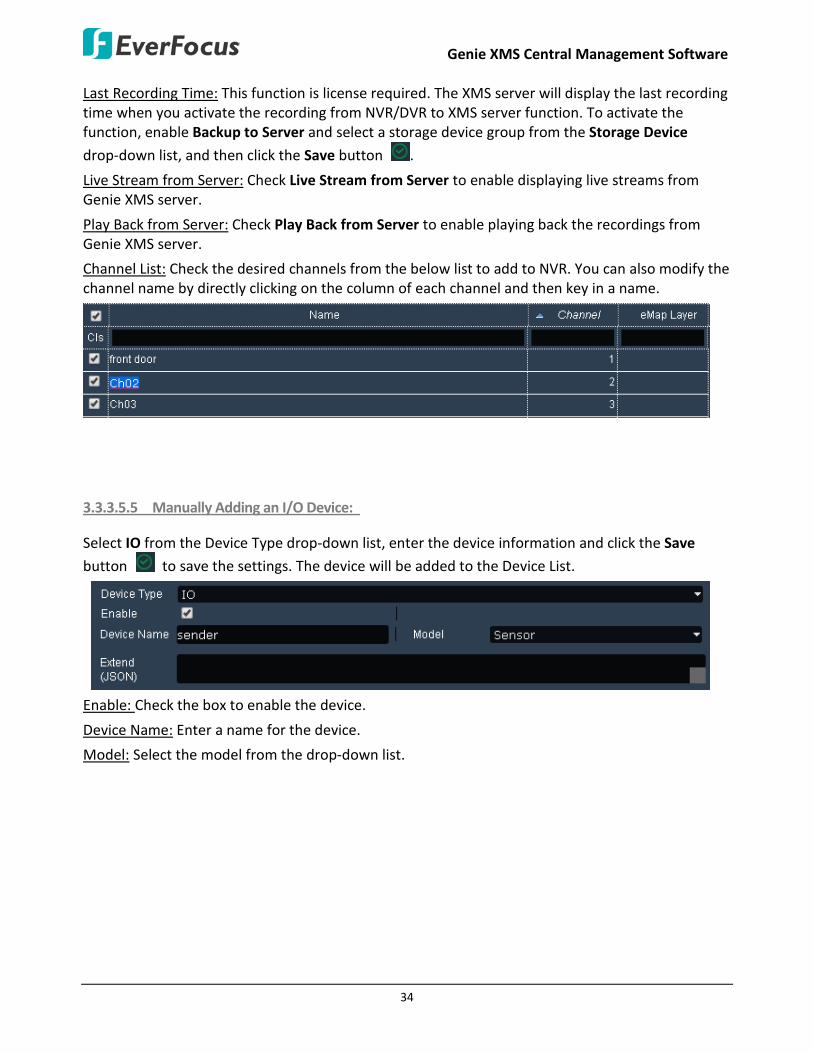
Last Recording Time: This function is license required. The XMS server will display the last recording time when you activate the recording from NVR/DVR to XMS server function. To activate the function, enable Backup to Server and select a storage device group from the Storage Device
drop-down list, and then click the Save button .
Live Stream from Server: Check Live Stream from Server to enable displaying live streams from Genie XMS server.
Play Back from Server: Check Play Back from Server to enable playing back the recordings from Genie XMS server.
Channel List: Check the desired channels from the below list to add to NVR. You can also modify the channel name by directly clicking on the column of each channel and then key in a name.
3.3.3.5.5 Manually Adding an I/O Device:
Select IO from the Device Type drop-down list, enter the device information and click the Save
button to save the settings. The device will be added to the Device List.
Enable: Check the box to enable the device.
Device Name: Enter a name for the device.
Model: Select the model from the drop-down list.

Genie XMS Central Management Software
35
3.3.3.5.6 Manually Adding a (Mobile) DVR:
Select DVR from the Device Type drop-down list, enter the device information, select the desired
channels of the device, and then click the Save button to save the settings. The device will be
added to the Device List. You can also click the Open Setting Page button to access the Web interface of the device.
Enable: Check the box to enable the device.
Device Name: Enter a name for the device.
IP: Enter the IP of the Device.
HTTP Port: By default, the port is set to 80. Change the port number if necessary.
Model: Select the model from the drop-down list.
Storage Device: Select a storage device for the auto backup function. To setup the storage device, please see To create a new group in 4.3.2 Storage Device Management.
Note: If both of the “IP camera / RTSP device schedule recording” and “DVR / NVR auto backup” functions have been enabled on your Genie XMS server, please assign different Storage Device group to IP camera / RTSP device and DVR / NVR. For example, assign Storage Device A to IP camera and Storage Device B to DVR.
User Account: Enter the user ID of the device.
Password: Enter the password of the device.

Genie XMS Central Management Software
36
Live: Select Main or Sub for live view displaying.
Recording: Select Main or Sub for the recording.
Network ID: Enter a 10-digit ID for network identification.
Backup to Server: Check the box to enable the Auto Backup Recording function (see 3.4.4 Auto Backup Recording).
Note: To archive the recordings from DVR, NVR and Mobile DVR in AVI/MP4 format, the Backup to Server function must be checked on the device Maintain page. If the option is unchecked, the recordings will be archived in AVR format (directly archived from the device HDD), and you have to use EverFocus’ players such as EFPlayer or EF-Reader to play back the recordings.
Port Forwarding: Check the box and then click the Save button to enable the Port Forwarding function. The port number assigned by the XMS server will be displayed in the Forward Port Number field. This function is useful if you want to remotely access XMS server and view the streams or remotely access the device live view from outside of the LAN via the internet (WAN). For this function to work, you have to configure the network setting in advance (see 4.4.1 Network Setting). To remotely access the device live view through WAN, simply type the IP address appended with forwarded port number (for example http://118.122.53.106:20003) in the address field of a browser.
Forward Port Number: After enabling the Port Forwarding function and then click the Save button
, the port number assigned by the XMS server will be displayed in this field.
Last Recording Time: This function is license required. The XMS server will display the last recording time when you activate the recording from NVR/DVR to XMS server function. To activate the function, enable Backup to Server and select a storage from the Storage Device drop-down list, and
then click the Save button .
Live Stream from Server: Check Live Stream from Server to enable displaying live streams from Genie XMS server. For mobile DVRs, please ensure the device is connected to the system with a physical IP address instead of a virtual IP address or the function will not work.
Play Back from Server: Check Play Back from Server to enable playing back the recordings from Genie XMS server.
Channel List: Check the desired channels from the below list to add to (Mobile) DVR. You can also modify channel names by directly clicking on the column of each channel and then key in a name.

Genie XMS Central Management Software
37
3.3.3.5.7 Manually Adding a Genie XMS Server:
You can add multiple Genie XMS servers to the system. For more details, please refer to 3.7 Genie XMS Servers Management. Select XMS from the Device Type drop-down list, enter the device
information and click the Save button to save the settings. The device will be added to the
Device List. You can also click Open Setting Page to access the Web interface of the device.
Enable: Check the box to enable the device. Device Name: Enter a name for the device. IP: Enter the IP of the Device. HTTP Port: By default, the port is set to 80. Change the port number if necessary. RTSP Port: Enter the RTSP port. Network Type: Select a network type. User Account: Enter the user ID of the device. Password: Enter the password of the device.
Port Forwarding: Check the box and then click the Save button to enable the Port Forwarding function. The port number assigned by the XMS server will be displayed in the Forward Port Number field. This function is useful if you want to remotely access XMS server and view the streams or remotely access the device live view from outside of the LAN via the internet (WAN). For this function to work, you have to configure the network setting in advance (see 4.4.1 Network Setting). To remotely access the device live view through WAN, simply type the IP address appended with forwarded port number (for example http://118.122.53.106:20003) in the address field of a browser.
Forward Port Number: After enabling the Port Forwarding function and then click the Save button
, the port number assigned by the XMS server will be displayed in this field.
Channel List: Check the desired IP cameras from the list to be added to this XMS device.

Genie XMS Central Management Software
38
3.3.3.5.8 Manually Adding a Web Page:
Select Web from the Device Type drop-down list, check the Enable box, enter a name for the Web
page, enter the Web URL, and then click the Save button to save the settings. The Web page will be added to the Device List.
3.3.3.5.9 Manually Adding a Message:
Select Message from the Device Type drop-down list, enter the message information and click the
Save button to save the settings. The message will be added to the Device List.
Enable: Check the box to enable the message.
Name: Enter a name for the message.
Method: Select Text to display the text or Marquee to display the text in marquee mode on the Live View window.
Font: Enter a font size for the text.
Message: Enter the message.
Genie XMS Central Management Software
39
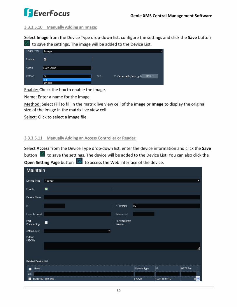
3.3.3.5.10 Manually Adding an Image:
Select Image from the Device Type drop-down list, configure the settings and click the Save button
to save the settings. The image will be added to the Device List.
Enable: Check the box to enable the image.
Name: Enter a name for the image.
Method: Select Fill to fill in the matrix live view cell of the image or Image to display the original size of the image in the matrix live view cell.
Select: Click to select a image file.
3.3.3.5.11 Manually Adding an Access Controller or Reader:
Select Access from the Device Type drop-down list, enter the device information and click the Save
button to save the settings. The device will be added to the Device List. You can also click the
Open Setting Page button to access the Web interface of the device.

Genie XMS Central Management Software
40
Enable: Check the box to enable the device.
Device Name: Enter a name for the device.
IP: Enter the IP of the Device.
HTTP Port: By default, the port is set to 80. Change the port number if necessary.
User Account: Enter the user ID of the device.
Password: Enter the password of the device.
Port Forwarding: Check the box and then click the Save button to enable the Port Forwarding function. The port number assigned by the XMS server will be displayed in the Forward Port Number field. This function is useful if you want to remotely access XMS server and view the streams or remotely access the device live view from outside of the LAN via the internet (WAN). For this function to work, you have to configure the network setting in advance (see 4.4.1 Network Setting). To remotely access the device live view through WAN, simply type the IP address appended with forwarded port number (for example http://118.122.53.106:20003) in the address field of a browser.
Forward Port Number: After enabling the Port Forwarding function and then click the Save button
, the port number assigned by the XMS server will be displayed in this field.
eMap Layer: Select an eMap layer to apply this device to. This eMap layer will be applied with the Go to eMap Layer function when event occurs (see 3.3.1.1 Go to eMap Layer).
Related Device List: For certain functions, it’s required to establish the connection among devices, and the related devices will be listed here (see 5.2.3 Setting up Event Configurations). 3.3.3.5.12 Manually Adding an Access Management Software (ENS2000):
Select Access Server from the Device Type drop-down list, enter the device information and click
the Save button to save the settings. The device will be added to the Device List. You can also
click the Open Setting Page button to access the Web interface of the device.

Genie XMS Central Management Software
41
Enable: Check the box to enable the device.
Device Name: Enter a name for the device.
IP: Enter the IP of the Device.
HTTP Port: By default, the port is set to 80. Change the port number if necessary.
User Account: Enter the user ID of the device.
Password: Enter the password of the device.
Port Forwarding: Check the box and then click the Save button to enable the Port Forwarding function. The port number assigned by the XMS server will be displayed in the Forward Port Number field. This function is useful if you want to remotely access XMS server and view the streams or remotely access the device live view from outside of the LAN via the internet (WAN). For this function to work, you have to configure the network setting in advance (see 4.4.1 Network Setting). To remotely access the device live view through WAN, simply type the IP address appended with forwarded port number (for example http://118.122.53.106:20003) in the address field of a browser.
Forward Port Number: After enabling the Port Forwarding function and then click the Save button
, the port number assigned by the XMS server will be displayed in this field.
Used: Select Used / Unused to enable / disable the access control event function.
Related Device List: For certain functions, it’s required to establish the connection among devices, and the related devices will be listed here (see 5.2.3 Setting up Event Configurations).

Genie XMS Central Management Software
42
3.3.3.5.13 Automatically Adding Devices:
On the Live View Window, click Setting to bring up the left-side setting menu. Click Device in the Device Setting field, the Device List Setup page appears on the right window. Click the Add button on the upper-right corner, the Maintain page appears.
Click the Auto Detection icon on the Maintain page to switch to the Auto Detection page. The system will automatically display the devices connected on the same network.
1. Check the box beside the Device Name to select a desired device. (Note: If multiple devices have the same ID and Password, you can select multiple devices for this step).
2. Type the device ID and Password in the columns.
3. Click the Apply to Select button to apply the input ID and Password to the selected
devices.
4. Click the Authentication button , the verified devices will be marked with a check mark.
5. Click the Save button , the device will be listed on the Device List.
You can optionally sort the Device List by clicking each item column on the top, or key in the column to filter a certain device type, model, etc.
Genie XMS Central Management Software
43
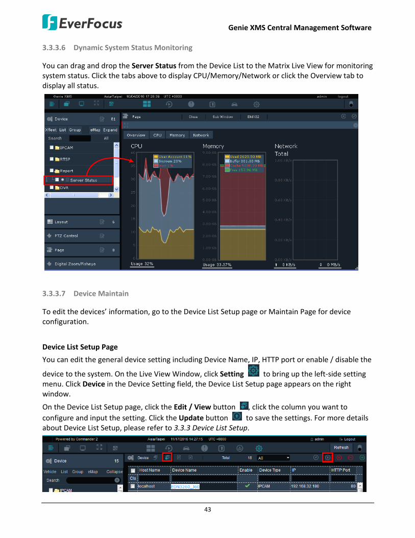
3.3.3.6 Dynamic System Status Monitoring
You can drag and drop the Server Status from the Device List to the Matrix Live View for monitoring system status. Click the tabs above to display CPU/Memory/Network or click the Overview tab to display all status.
3.3.3.7 Device Maintain
To edit the devices’ information, go to the Device List Setup page or Maintain Page for device configuration.
Device List Setup Page
You can edit the general device setting including Device Name, IP, HTTP port or enable / disable the
device to the system. On the Live View Window, click Setting to bring up the left-side setting menu. Click Device in the Device Setting field, the Device List Setup page appears on the right window.
On the Device List Setup page, click the Edit / View button , click the column you want to configure and input the setting. Click the Update button to save the settings. For more details about Device List Setup, please refer to 3.3.3 Device List Setup.

Genie XMS Central Management Software
44
Maintain Page
You can edit the overall device settings on this page. On the Live View Window, click Setting to bring up the left-side setting menu. Click Device in the Device Setting field, the Device List Setup page appears on the right window.
On the Device List Setup page, double click on a device, the Maintain page appears (see 3.3.3.5
Adding Devices). Configure the settings and then click the Save button . You can also click the Open Setting Page button to enter the Web interface of the device. Or click the Preview
button to preview the device live view.
To edit the device configurations through the XMS server:
Click the Get Configuration tab, the device information will be displayed. Edit the configurations
and click the Save button . The configurations will be applied to the device. You can click the Get
Configuration button for the XMS server to re-get the device information.

Genie XMS Central Management Software
45
3.3.4 Layout Setting
You can configure the live view layout or create personalized live view layout on this page. On the Live View Window, click Layout from the left-side bar, the layout template displayed (1+3, 2+3, 2x2, 3x3, 4x4).
1 2 3 4 75 6
No. Name Description
1 Layout Click to enter the layout page for layout selection.
2 Layout Detail Click to enter the Layout Design page. You can further create or customize the layout. The number besides the icon indicates the created number of layout on the Layout Template.
3 Page Name Displays the name of the current page.
4 Close Click to close all the device streams on the current live view layout.
5 Sub Window
Click to open a sub window for displaying the current matrix live view on additional monitor. The number of sub window is unlimited. The sub window live view depends on the current matrix live view displayed on the Genie XMS.
6 EMX32 Click to display the Matrix Live View on the monitor of EMX32 (see 4.5.9 EMX32).
7 Save Click to Add or Update the current live layout as a Page in the Page List (see 3.3.4 Layout Setting).
Genie XMS Central Management Software
46
To apply the devices to the live view layout:
1. On the Live View Window, click Layout from the left-side bar and select a layout.
2. Click Device, drag and drop the devices from the Device List to the layout cells.
3. To save this layout as a page, enter a name for this layout page in the Page column and then
click the Save button on the upper-right window. The layout page will be saved to the Page field. You can then use the Sequence function to display multiple live view layouts in turns (see 3.3.5 Page Sequence).
4. If you want the system to display a certain page on the Live View window every time when you log in the system, select a page by directly clicking on it on the page list to save the setting.
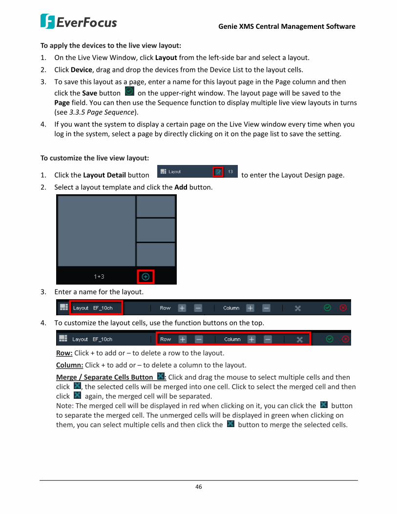
To customize the live view layout:
1. Click the Layout Detail button to enter the Layout Design page.
2. Select a layout template and click the Add button.
3. Enter a name for the layout.
4. To customize the layout cells, use the function buttons on the top.
Row: Click + to add or – to delete a row to the layout.
Column: Click + to add or – to delete a column to the layout.
Merge / Separate Cells Button : Click and drag the mouse to select multiple cells and then click , the selected cells will be merged into one cell. Click to select the merged cell and then click again, the merged cell will be separated. Note: The merged cell will be displayed in red when clicking on it, you can click the button to separate the merged cell. The unmerged cells will be displayed in green when clicking on them, you can select multiple cells and then click the button to merge the selected cells.

Genie XMS Central Management Software
47
5. Click the Save button , the customized layout will be added to the Layout template.
6. To apply the devices to this layout, click Device, drag and drop the devices from the Device List
to the layout cells.
7. To save this layout as a page, enter a name for this layout page in the Page column and then
click the Save button on the upper-right window. The layout page will be saved to the Page field. You can then use the Sequence function to display multiple live view layouts in turns (see 3.3.5 Page Sequence).
8. If you want the system to display a certain page on the Live View window every time when you log in the system, select a page by directly clicking on it on the page list to save the setting.
Genie XMS Central Management Software
48
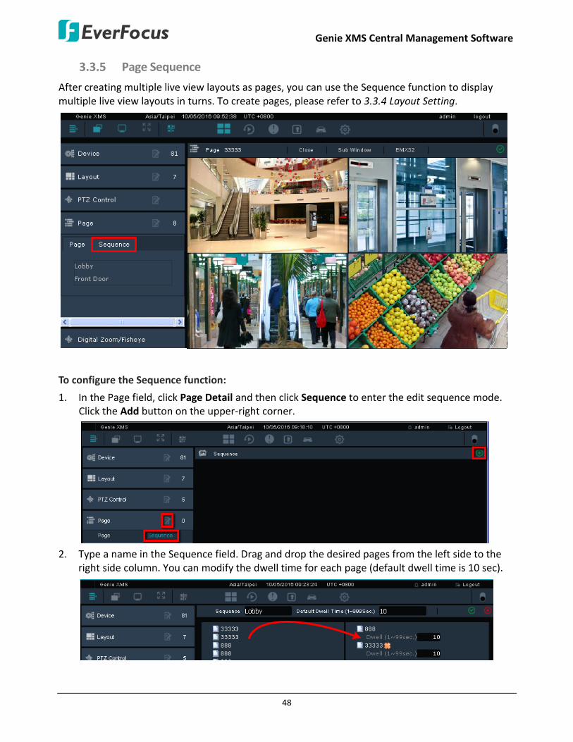
3.3.5 Page Sequence
After creating multiple live view layouts as pages, you can use the Sequence function to display multiple live view layouts in turns. To create pages, please refer to 3.3.4 Layout Setting.
To configure the Sequence function:
1. In the Page field, click Page Detail and then click Sequence to enter the edit sequence mode. Click the Add button on the upper-right corner.
2. Type a name in the Sequence field. Drag and drop the desired pages from the left side to the
right side column. You can modify the dwell time for each page (default dwell time is 10 sec).

Genie XMS Central Management Software
49
3. Click the Add button , an ADD_SUCCESS message appears on the bottom-left to indicate this action is done successfully. And this Sequence is added to the Sequence list.
4. Click the added Sequence on the Sequence list, the Sequence function will start.
5. Click the Stop button to pause the sequence or click the Sub Window button to open a sub window of this sequence. You can drag and drop this window on additional monitor for sequence display.

Genie XMS Central Management Software
50
To modify camera streams on the page layout:
1. On the Live View Window, click the Page Detail button .
2. Select a page and then click the Edit button.
3. Click Device, drag and drop the devices from the Device List to the layout cells.
4. Optionally change the page name or use the function buttons on the bar above.
Page: Enter a page name.
Close: Click to close the camera streams on the current layout.
Sub Window: Click to open a sub window for the current layout. You can display this window on additional monitor.
EMX32: This function only appears for the 2x2, 3x3 and 4x4 layout. Click to display the Matrix Live View on the monitor of EMX32. To activate this function, please configure the EMX32 setting in advance (see 4.5.9 EMX32).
5. Click the Save button to save the settings.

Genie XMS Central Management Software
51
3.3.6 PTZ Control
You can remotely control the IP Speed Dome cameras or configure their settings through the system. By setting up the Preset Position, Auto Pan, Tour and Pattern functions, you can force the camera to move to a certain position or to move in a setup sequence (see 3.3.6.2 PTZ Control Panel).
3.3.6.1 Live View PTZ Control
You can use your mouse to control the direction and zoom function of an IP speed dome camera on the matrix live view.
1. On the Live View window, click Device from the left-side menu, drag and drop an IP speed dome camera from the Device List to the matrix live view.
2. Select the IP speed dome camera by clicking on the channel. The selected camera will be highlighted with a red frame.
3. Move your mouse cursor over the IP speed dome camera channel on the matrix live view, the mouse cursor will turn into a direction icon (8 directions). When your mouse cursor turns into a direction icon, click the mouse will force the camera to turn into that direction.
4. To zoom in / out the camera, move your mouse cursor over the IP speed dome camera channel on the matrix live view, and then scroll the mouse.
5. You can double click the channel to enable / disable the full screen function.

Genie XMS Central Management Software
52
3.3.6.2 PTZ Control Panel
The PTZ Control Panel is designed to remotely control the IP speed dome cameras connected to the system. After configuring the PTZ settings, you can activate the functions in the Actions Control Buttons field. To bring up the PTZ Control Panel, on the Live View window, click PTZ Control on the left-side menu.
Click to enter the PTZ Setting page
Click the direction buttons to force the camera to turn into that direction
Click to stop the current action, such as Auto Pan, Tour or Pattern
Click to Zoom In
Click to Zoom OutClick to Focus Near / Far
Click to Open / Close Iris
Click to select a speed for Pan and Tilt
Actions Control Buttons
Click to enable / disable the EKB200
Note: The Zoom In / Out function can also be applied to EverFocus EHN3261/3361 and EZN3261/3361 cameras.
Actions Control Buttons
Preset
To force the camera to turn to the preconfigured preset position, click the Preset button, key in a preset number in the Blank and then click the Go button. Note: To use this function, you have to set a preset position (see 3.3.6.3 Set Preset).
Auto Pan
To force the camera to pan automatically, click the Auto Pan button, enter 1 or 2 in the Blank and then click the Go button. (“1” for point-to-point pan and “2” for endless 360°pan) Note: To use this function, you have to set up an auto pan sequence or endless pan speed (see 3.3.6.4 Auto Pan).
Pattern To move the camera in a preconfigured sequence movement, click the Pattern button, key in a pattern number in the Blank and then click the Go button. Note: To use this function, you have to set up a pattern (see 3.3.6.5 Set Pattern).

Genie XMS Central Management Software
53
Tour
To move the camera in a preconfigured sequence consists of a selection of Patterns and Preset Positions, click the Tour button, key in a tour number in the Blank and then click the Go button. Note: To use this function, you have to set up at least one tour (see 3.3.6.6 Set Tour).
Auto Pan (T)
To activate the Auto Tracking function in the Auto Pan mode, click the Auto Pan (T) button and then click the Go button. Note: To use this function, you have to set up an auto pan sequence (see 3.3.6.4 Auto Pan) and Auto Tracking function (see 3.3.6.7 Auto Tracking).
Tour (T)
To activate the Auto Tracking function in the Tour mode, click the Tour (T) button, key in a tour number in the Blank and then click the Go button. Note: To use this function, you have to set up at least one tour (see 3.3.6.6 Set Tour) and Auto Tracking function (see 3.3.6.7 Auto Tracking).
Blank Key in a number for a Preset, Auto Pan, Pattern or Tour.
Clear Click this button to clear the entered number.
Go Click this button to activate the selected action number.

Genie XMS Central Management Software
54
3.3.6.3 Set Preset
You can configure up to 192 preset positions on this page.
1. Click the PTZ Detail button to enter the PTZ setting page.
2. Click the Channel List button to select an IP speed dome camera. The camera live view should
display above the PTZ Control Pad.
3. Adjust the camera view to a desired position using the direction button. You can select the pan / tilt speed from the Speed drop-down list for controlling the direction buttons. Adjust zoom, focus and Iris if necessary.
4. To set up the current camera view as a preset position, select a page number and select a preset number from the No. drop-down list and then click the Set button.
5. Optionally set up a title for this preset position view and then click the Apply button.
6. Follow Step 4 to 6 to set up another preset position.
To activate the Preset function on the Live View window:
1. On the Live View window, click Device from the left-side menu, drag and drop an IP speed dome camera from the Device List to the matrix live view.
2. Select the IP speed dome camera by clicking on the channel. The selected camera will be highlighted with a red frame.
3. On the PTZ Control Panel, click the Preset button, enter a preset number in the Blank and then click the Go button.
4. To stop the action, click Stop on the PTZ Control Panel.
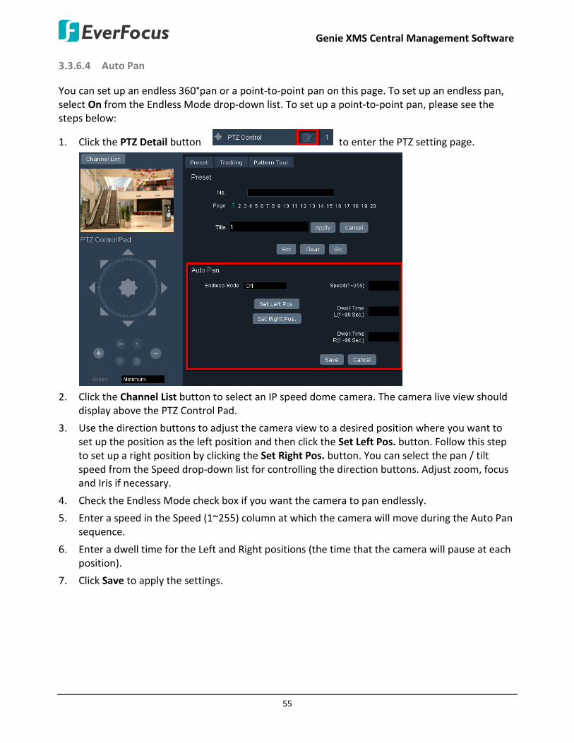
Genie XMS Central Management Software
55
3.3.6.4 Auto Pan
You can set up an endless 360°pan or a point-to-point pan on this page. To set up an endless pan, select On from the Endless Mode drop-down list. To set up a point-to-point pan, please see the steps below:
1. Click the PTZ Detail button to enter the PTZ setting page.
2. Click the Channel List button to select an IP speed dome camera. The camera live view should
display above the PTZ Control Pad.
3. Use the direction buttons to adjust the camera view to a desired position where you want to set up the position as the left position and then click the Set Left Pos. button. Follow this step to set up a right position by clicking the Set Right Pos. button. You can select the pan / tilt speed from the Speed drop-down list for controlling the direction buttons. Adjust zoom, focus and Iris if necessary.
4. Check the Endless Mode check box if you want the camera to pan endlessly.
5. Enter a speed in the Speed (1~255) column at which the camera will move during the Auto Pan sequence.
6. Enter a dwell time for the Left and Right positions (the time that the camera will pause at each position).
7. Click Save to apply the settings.

Genie XMS Central Management Software
56
To activate the point-to-point Pan function on the Live View window:
1. On the Live View window, click Device from the left-side menu, drag and drop an IP speed dome camera from the Device List to the matrix live view.
2. Select the IP speed dome camera by clicking on the channel. The selected camera will be highlighted with a red frame.
3. On the PTZ Control Panel, click the Auto Pan button, enter 1 in the Blank and then click the Go button.
4. To stop the action, click Stop on the PTZ Control Panel.
To activate the endless 360°pan function on the Live View window:
1. After selecting On from the Endless Mode drop-down list on the PTZ Setting page, on the Live View window, click Device from the left-side menu, drag and drop an IP speed dome camera from the Device List to the matrix live view.
2. Select the IP speed dome camera by clicking on the channel. The selected camera will be highlighted with a red frame.
3. On the PTZ Control Panel, click the Auto Pan button, enter 2 in the Blank and then click the Go button.
4. To stop the action, click Stop on the PTZ Control Panel.
Note: The 360°pan or a point-to-point pan cannot be used simultaneously. To use the 360°pan function, select On from the Endless Mode drop-down list on the PTZ Setting page. To use the point-to-point pan function, select Off from the Endless Mode drop-down list and then configure the settings on the PTZ Setting page.

Genie XMS Central Management Software
57
3.3.6.5 Set Pattern
You are given 90 seconds to move the camera (via the PTZ buttons) to different positions (and different zoom / focus / Iris positions). The camera then saves that sequence under the Pattern No. you’ve selected. Up to 4 Patterns can be configured.
To set up a Pattern Sequence:
1. Click the PTZ Detail button to enter the PTZ setting page. And then click the Pattern Tour tab.
2. Click the Channel List button to select an IP speed dome camera. The camera live view should
display above the PTZ Control Pad.
3. Select a pan and tilt speed from the Speed drop-down list for the camera to move to the directions when you use the direction buttons during the configuration period.
4. Select a pattern number from the Pattern No drop-down list.
5. Click the Set button to start the 90-second configuration period. Use the direction / zoom / focus / Iris buttons to move the camera in the desired sequence.
6. Click the Complete button to end the configuration.
Click Clear can void the configuration for the entered Pattern No. Click Go to view/test the configured Pattern sequence.

Genie XMS Central Management Software
58
To activate the configured Pattern function on the Live View window:
1. On the Live View window, click Device from the left-side menu, drag and drop an IP speed dome camera from the Device List to the matrix live view.
2. Select the IP speed dome camera by clicking on the channel. The selected camera will be highlighted with a red frame.
3. On the PTZ Control Panel, click the Pattern button, enter a pattern number in the Blank and then click the Go button.
4. To stop the action, click Stop on the PTZ Control Panel.
3.3.6.6 Set Tour
You can combine up to 16 preconfigured camera positions and patterns into one long sequence. Up to 16 Tour sequences can be set up.
To set up a Tour Sequence:
1. Click the PTZ Detail button to enter the PTZ setting page. And then click the Pattern Tour tab.

Genie XMS Central Management Software
59
2. Select a tour number from the Tour No drop-down list.
3. Edit the configurations for this tour.
In the Edit Mode column: click “Preset” in the column to switch among Preset, Pattern and Off.
In the Value column: Enter a number for the Preset or Pattern.
In the Dwell column: Enter a number in sec. for the tour to pause at a position or after a pattern sequence.
In the Speed column: Enter a speed at which the camera will move to the Preset position or first point of the Pattern sequence.
4. Follow step 2 and 2 to configure up to 16 tour sequences.
5. Click the Apply button to save the settings.
To activate the configured Tour function on the Live View window:
1. On the Live View window, click Device from the left-side menu, drag and drop an IP speed dome camera from the Device List to the matrix live view.
2. Select the IP speed dome camera by clicking on the channel. The selected camera will be highlighted with a red frame.
3. On the PTZ Control Panel, click the Tour button, enter a tour number in the Blank and then click the Go button.
4. To stop the action, click Stop on the PTZ Control Panel.

Genie XMS Central Management Software
60
3.3.6.7 Auto Tracking
You can remotely configure the Auto Tracking function to the IP speed dome through the system. When a moving object appears in the field of view, the camera will automatically track the objects. You can optionally set up a limit zone or configure optional settings for the Auto Tracking function.
To enable the Auto Tracking function:
1. Click the PTZ Detail button to enter the PTZ setting page. And then click the Tracking tab.
2. Click the Channel List button to select an IP speed dome camera. The camera live view should
display above the PTZ Control Pad.
3. To enable the Auto Tracking function, select On in the Auto Track field.
4. Click the Save button to save the settings.

Genie XMS Central Management Software
61
You can optionally configure the below settings for the Auto Tracking function:
Select Tracking Object: Click the button to select an object to start auto tracking.
Auto Tracking Start Point: Check the box to enable the camera to return to the start point when the camera loses track of the object.
To set up a start point, select a position using the PTZ Control Pad and then click the Set button in the Auto Tracking Start Point field.
Pan/Tilt Limit: Check the box if you want to create a zone where the camera will track the movement inside the zone only.
To set up the zone, select a right position using the PTZ Control Pad and then click the Right button in the Pan/Tilt Limit field. Follow this step to set up the up, down and left positions.
Note: Please note that if enabling the Pan/Tilt Limits function, the position of the Start Point should be within the range of the Pan/Tilt Limits.
Genie XMS Central Management Software
62
Zoom Control on Tracking: Select a zoom control mode from the drop-down list.
Keep Current Zoom Ratio: the current zoom ratio will stay fixed during the tracking process.
Multi-Step Zoom Function: the zoom ratio will change according to the distance of the object against the camera. When the object is moving further away, the camera will keep zooming in to track; on the other hand, when moving closer, the camera will zoom out to check whether it should track the object or not.
Tracking Duration: Set up a tracking duration in seconds for the camera to return to the Start Point. This function is used to prevent the camera from tracking an object which is intentionally set to lure the camera away.
When the object is lost on the screen: Users can select a tracking mode when the object is lost on the screen.
Keep tracking: The camera will stop at the current position and wait for another moving object in the camera's field of view. Then, the camera will track the new object without changing zoom ratio.
Zoom out and look for a new object: The camera will zoom out at the current position immediately for expanded FOV and restart tracking a new moving object appearing in the camera's field of view.
Stop tracking and zoom out: The camera will stop auto tracking and stay at the current position. Then, the camera will zoom out for expanded FOV.
In ___ sec and Back to Start Point: Set up a period of time for the camera to stay at the current position before returning to the Start Point (0 is returning to Start Point without any waiting).
Resume from manual stop: Set up the Auto Tracking restart time (0~600 seconds). If user manually operates the PTZ function during auto tracking process, the auto tracking function will stop. When the manual operation ceases, the camera will resume to “Auto Tracking Start Point” after a given period of time. Setting of value 0 indicates do not restart.

Genie XMS Central Management Software
63
3.3.7 Digital Zoom / Fisheye
You can use the Digital Zoom function for all the cameras on the matrix live view including IP cameras or cameras of (Mobile) DVR / NVR connected to the system. You can also display the fisheye camera in Original / Region / Panorama mode on the matrix live view.
3.3.7.1 Digital Zoom
To use the Digital Zoom function for all the cameras on the matrix live view including IP cameras or cameras of (Mobile) DVR / NVR connected to the system, follow the steps below:
Navigation BoxPreview Live View Window
1. On the Live View window, click Device from the left-side menu, drag and drop a camera from the Device List to the matrix live view.
2. Click Digital Zoom / Fisheye from the left-side menu.
3. Select a camera by clicking on the channel. The selected camera will be highlighted with a red frame and a Preview Live View window appears in the Digital Zoom / Fisheye field.
4. On the Preview Live View window, scroll your mouse to bring up the Navigation Box. You can scroll your mouse to adjust the zoom size.
5. Use your mouse to drag and move the Navigation Box around to have a close-up view within the area.
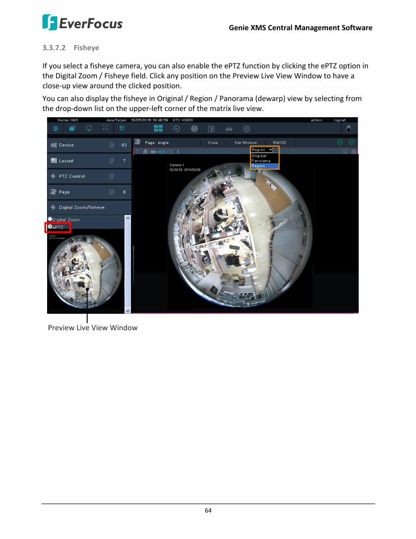
Genie XMS Central Management Software
64
3.3.7.2 Fisheye
If you select a fisheye camera, you can also enable the ePTZ function by clicking the ePTZ option in the Digital Zoom / Fisheye field. Click any position on the Preview Live View Window to have a close-up view around the clicked position.
You can also display the fisheye in Original / Region / Panorama (dewarp) view by selecting from the drop-down list on the upper-left corner of the matrix live view.
Preview Live View Window

Genie XMS Central Management Software
65
3.3.8 eZ Tracker
The eZ Tracker is a cutting-edge technology that realizes the synergy of EverFocus network fisheye and speed dome cameras. This technology not only obtains advantages from both types of cameras but also creates new value for wide-area surveillance without compromising the optimal image quality.
The eZ Tracker function allows users to control the IP speed dome camera through fisheye camera Web UI. This function can be easily operated using a mouse. Click a desired location on the 360° surround view from the fisheye camera and the speed dome camera will be exactly triggered to track the location. You can then utilize the smooth PTZ function on the speed dome camera view to zoom in or focus on a region of interest. Meanwhile, you can monitor all the movements from the 360° surround view.
Preview Live View Window

Genie XMS Central Management Software
66
Installation Notice
Before using the eZ Tracker function, you have to install the fisheye and IP speed dome cameras correctly. Ensure the following steps are properly done.
1. The fisheye camera must be installed with Ceiling Mount. The eZ Tracker function can only be applied for fisheye cameras mounted onto the ceiling.
2. The distance between the fisheye and IP speed dome cameras is suggested to be as close as possible. And the lenses of both cameras should be aligned horizontally (IP speed dome camera lens face down).
Horizontally align the lenses
Distance as close as possible To enable the eZ Tracker function, you have to determine a fisheye camera and an IP speed dome camera as a set, and then configure the calibration settings.
To determine a fisheye camera and an IP speed dome camera as a set:
1. On the Live View Window, click Setting to bring up the left-side setting menu. Click Device in the Device Setting field, the Device List Setup page appears on the right window.
2. Double click the desired fisheye camera to enter its Maintain page.
3. In the Related Device List field, select an IP speed dome camera by checking the box.
4. Click the Save button to save the settings. On the Device List, you can see the IP speed dome camera listed under the fisheye to indicate that the fisheye camera and IP speed dome camera have been determined as a set.

Genie XMS Central Management Software
67
To configure the calibration setting:
1. On the Live View window, click the PTZ Detail button and then click Fisheye Calibration Setting.
2. Click the Channel List button to select a fisheye camera. The camera live view should display
below the Channel List button.
3. Click the Calibration Setting button , the Step 1 Instruction appears. The IP speed dome window will be highlighted with a yellow frame. Find an object in the IP speed dome window and position it to the center (red square) by directly clicking on the window. You can refer to the image below for moving the speed dome image. For example, if you click on the left-arrow image division, the camera will go left. Repeat this until the target object is adjusted to the center of the window.
Target Object
4. When the target object is placed to the center window of the speed dome, click the Calibrate
button, the fisheye window should be highlighted with a yellow frame.

Genie XMS Central Management Software
68
5. On the fisheye window, find the target object you placed in the center of the speed dome window, and then click it.
Click it Target Object
6. Test the calibration result by clicking any location on the fisheye window, and the location
should be displayed on the center of the speed dome window.
a. If the calibration result is ok. Click the OK button to complete the setting. b. If you want to fine-tune the calibration, click the Fine Adjustment button. c. If you want to retry the calibration, click the Retry button.
7. After clicking the Fine Adjustment button, a yellow square should appear on the fisheye window. On the speed dome window, find the object inside the yellow square of the fisheye window, and use the Left or Right Arrow buttons to move the speed dome window in order to make the object place to the center of the window. The system will calibrate the images automatically every time when you click the Arrow buttons.
Click the Left Arrow button to move the speed dome window in order to make this object place to the center of the window.

Genie XMS Central Management Software
69
8. Test the calibration result. Click any position on the fisheye window, and the speed dome camera will track the position and display the field of view.
9. Optionally repeat Step 7 and 8 to fine-tune the calibration.
10. Click the OK button to complete the setting.
To activate the eZ Tracker function:
1. On the Live View window, click Device from the left-side menu, drag and drop the configured fisheye and IP speed dome cameras from the Device List to the matrix live view.
2. Click Digital Zoom / Fisheye from the left-side menu and then click ez Tracker.
3. Select the IP speed dome camera by clicking on the channel. The selected camera will be highlighted with a red frame and the fisheye Preview Live Window appears in the Digital Zoom / Fisheye field.
Preview Live View Window 4. Click a desired location on the fisheye Preview Live Window and the speed dome camera will
be exactly triggered to track the location.
5. You can also use the Digital Zoom function (see 3.3.7 Digital Zoom / Fisheye) under eZ Tracker mode.
a. On the fisheye Preview Live View window, scroll your mouse to bring up the Navigation Box. You can scroll your mouse to adjust the zoom size.
b. Use your mouse to drag and move the Navigation Box around to have a close-up view within the area of the IP speed dome camera.

Genie XMS Central Management Software
70
3.4 Recording You can record camera live view to your computer. You can also use the Schedule function to set up a weekly recording schedule for the IP cameras.
3.4.1 Live View Recording
The Live View Recording is designed to record device live view from IP camera or any camera from the DVR / NVR connected to the system. The recordings will be stored to your computer in AVI format. To set up the recording path, please refer to 3.4.3 Setting up the Recording Path.
To use the Live View Recording function:
1. On the Live View Window, click the Option button, the Live View Tool Bar appears (see image above).
2. Click the Record button to start / stop live view recording locally. You have to set up the recording path for the recordings in advance (see 3.4.3 Setting up the Recording Path).
3. Go to the storage path, use any AVI-supported player to play back the recordings.

Genie XMS Central Management Software
71
3.4.2 Schedule Recording
After the Schedule function is set up, the camera recordings will be stored in the system. You can then remotely play back the recording (see 3.5.1 Remote Playback). At present, the Schedule Recording function can only be applied to IP camera and RTSP devices.
Note: To enable schedule recording to the system, you have to assign the hard disks connected to the system to a group first (see To create a new group in 4.3.2 Storage Device Management) and then enable the Record to Server function on the Device Maintain page (see 3.3.3.5.1 Manually Adding an IP Camera and 3.3.3.5.2 Manually Adding an RTSP Device).
On the Live View Window, click the Setting button, click the Record & Play menu bar on the left, click Schedule, the following Schedule page appears.
Normal + Event (Blue): This recording type button represents Continuous and Event recordings.
Event (Yellow): This recording type button represents Event recordings only.
No Record (Dark Gray): This recording type button represents No recording.
Note: For Event recordings, you have to configure the event settings in advance. On the Live View Window, click the Setting button and then click Event on the menu bar to enter the Event Setting page (see 4.2 Event).
Related Device List: Click to display the devices connected to the system. Select the desired devices to apply the setup schedule.
Schedule Name List: Click to display the schedule list. Select a desired schedule and click Apply.
Add: Click to add a new schedule.
Apply: Click to apply the schedule to the system.
Cancel: Click to cancel the current setting.
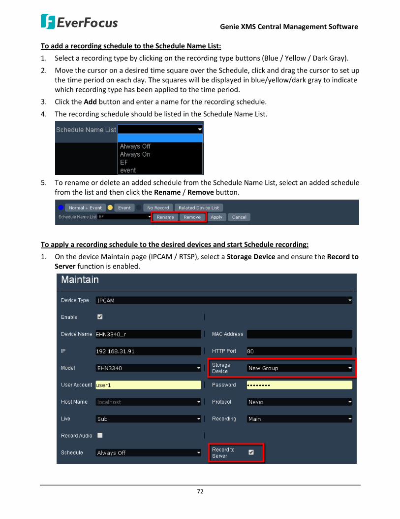
Genie XMS Central Management Software
72
To add a recording schedule to the Schedule Name List:
1. Select a recording type by clicking on the recording type buttons (Blue / Yellow / Dark Gray).
2. Move the cursor on a desired time square over the Schedule, click and drag the cursor to set up the time period on each day. The squares will be displayed in blue/yellow/dark gray to indicate which recording type has been applied to the time period.
3. Click the Add button and enter a name for the recording schedule.
4. The recording schedule should be listed in the Schedule Name List.
5. To rename or delete an added schedule from the Schedule Name List, select an added schedule
from the list and then click the Rename / Remove button.
To apply a recording schedule to the desired devices and start Schedule recording:
1. On the device Maintain page (IPCAM / RTSP), select a Storage Device and ensure the Record to Server function is enabled.

Genie XMS Central Management Software
73
2. On the Schedule Setting page, click the Related Device List button, select the desired devices and then click the Save button.
3. Select a desired recording schedule from the Schedule Name List drop-down list and then click
the Apply button.

Genie XMS Central Management Software
74
3.4.3 Setting up the Recording Path
On the Live View Window, click the Setting button, click the User Setting menu bar on the left and click Local Save Settings to enter the Local Save Settings page.
To set up the recording path:
1. Click the Select button in the Save Recording in field to select a path for the recordings.
2. Click the Apply button to save the settings.

Genie XMS Central Management Software
75
3.4.4 Auto Backup Recording
For DVR / NVR / Mobile DVR, you can set up the Auto Backup Recording function for XMS server to automatically backup the recordings from the devices to the Genie XMS server.
To activate the Auto Backup recording function, on the Device Maintain page, make sure the Storage Device and Backup to Server have been set up and enabled.
Note: If both of the “IP camera / RTSP device schedule recording” and “DVR / NVR auto backup” functions have been enabled on your Genie XMS server, please assign different Storage Device group to IP camera / RTSP device and DVR / NVR. For example, assign Storage Device A to IP camera and Storage Device B to DVR.
Once the set up is done, the Genie XMS server will dynamically update the last recording time in the Last Recording Time column.

Genie XMS Central Management Software
76
If you want to view the auto backup status of all devices, go to System > System Information > Recording Data Report.
1. Click to select a Date and Time.
2. Click Related Device List to select devices.
3. Click Query to display the recording status report.
4. You can click the bar under the Day or Hour to show the report in different timeline formats.
5. Click Today to show today’s data; click < or > to see the previous or the next day.
The recording status indication:
: A yellow block represents only events are recorded during this time block.
: A blue block indicates the continuous recording during this time block.
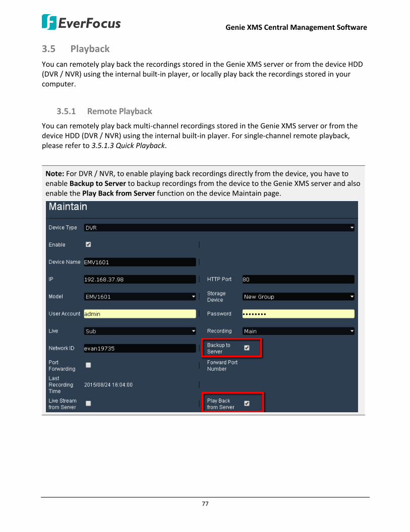
Genie XMS Central Management Software
77
3.5 Playback You can remotely play back the recordings stored in the Genie XMS server or from the device HDD (DVR / NVR) using the internal built-in player, or locally play back the recordings stored in your computer.
3.5.1 Remote Playback
You can remotely play back multi-channel recordings stored in the Genie XMS server or from the device HDD (DVR / NVR) using the internal built-in player. For single-channel remote playback, please refer to 3.5.1.3 Quick Playback.
Note: For DVR / NVR, to enable playing back recordings directly from the device, you have to enable Backup to Server to backup recordings from the device to the Genie XMS server and also enable the Play Back from Server function on the device Maintain page.
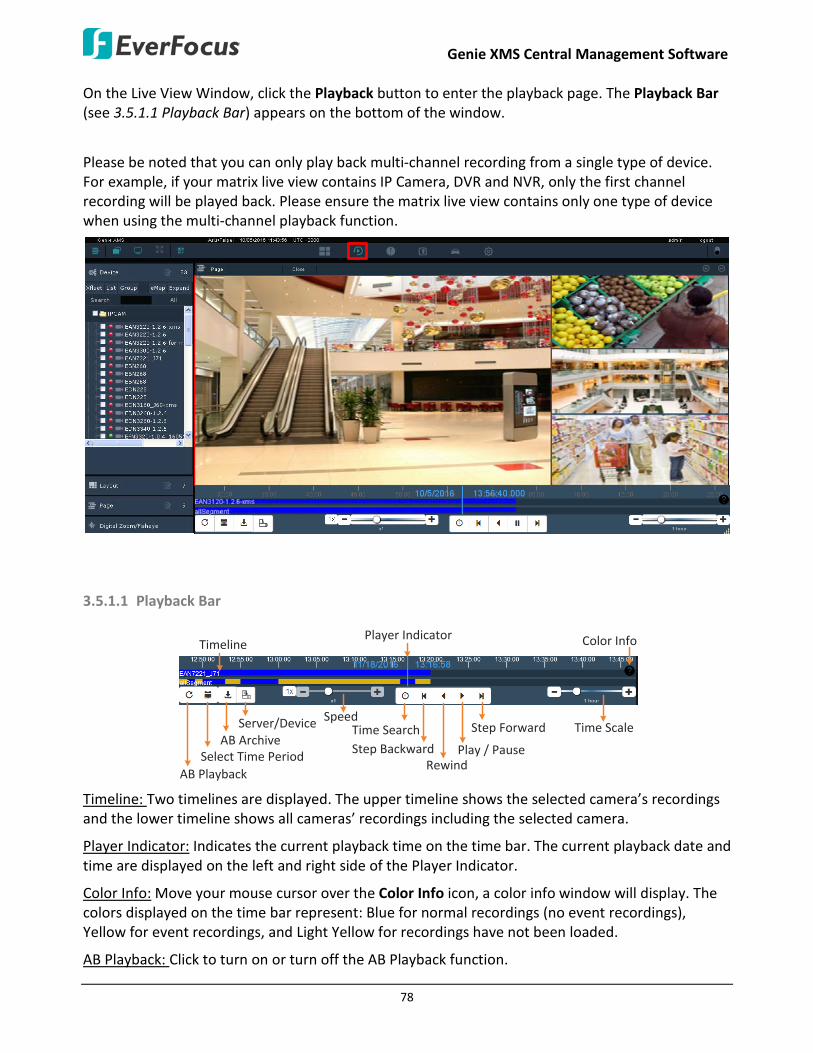
Genie XMS Central Management Software
78
On the Live View Window, click the Playback button to enter the playback page. The Playback Bar (see 3.5.1.1 Playback Bar) appears on the bottom of the window.
Please be noted that you can only play back multi-channel recording from a single type of device. For example, if your matrix live view contains IP Camera, DVR and NVR, only the first channel recording will be played back. Please ensure the matrix live view contains only one type of device when using the multi-channel playback function.
SD
3.5.1.1 Playback Bar
SD
Select Time PeriodRewind
Play / Pause
Step Forward
Player Indicator
Step Backward
Speed
Color Info
Time ScaleTime Search
AB Playback
Timeline
Server/DeviceAB Archive
Timeline: Two timelines are displayed. The upper timeline shows the selected camera’s recordings and the lower timeline shows all cameras’ recordings including the selected camera.
Player Indicator: Indicates the current playback time on the time bar. The current playback date and time are displayed on the left and right side of the Player Indicator.
Color Info: Move your mouse cursor over the Color Info icon, a color info window will display. The colors displayed on the time bar represent: Blue for normal recordings (no event recordings), Yellow for event recordings, and Light Yellow for recordings have not been loaded.
AB Playback: Click to turn on or turn off the AB Playback function.

Genie XMS Central Management Software
79
Select Time Period: Click to bring up the Select Time Period window for setting up a time range and then performing the AB Playback function. To disable the function, click the Turn On/Off AB Playback Mode button. Please refer to the steps below.
AB Archive: After setting up the time period, click Archive to archive the recordings of the selected time period. Please refer to the steps below.
Server/Device: This function is only available for DVR/NVR/Mobile DVR. You can choose to play back the recordings from the Device or Genie XMS Server. Click to switch between Server and Device. Note that to enable this function, you have to enable the Play Back from Server functions on the Device Maintain Page.
Speed: Click on + or – button or slide the bar to adjust the speed. Click the 1x button can quickly adjust the speed to 1x.
Time Search: Click to select a specific time and then click the Play button to start playing back.
Step Backward: Click to step backward frame by frame.
Rewind: Click to start backward playing back.
Play / Pause: Click to start playing back or pause playing back.
Step Forward: Click to step forward frame by frame.
Time Scale: Click on + or – button or slide the bar to adjust the time scale. You can directly click on the timeline and slide it to the left or right.
To remotely play back multi-channel recordings:
1. On the Live View Window, select a live view layout from the Layout list.
Note: You can only play back multi-channel recording from a single type of device. For example, if your matrix live view contains IP Camera, DVR and NVR, only the first channel recording will be played back. Please ensure the matrix live view contains only one type of device when using the multi-channel playback function..
2. Click the Playback button to enter the playback page. The Playback Bar appears on the bottom of the window.
3. Search for the specific time you want to play back.
a. Move your mouse cursor over the Time Bar, drag the Time Bar to the left or right.
b. Click the Time Search button on the Playback Bar.
4. Use the function buttons on the Playback Bar for playing back.

Genie XMS Central Management Software
80
To enable the AB Playback function:
1. Click the Select Time Period button to bring up the setting window for setting up a time range.
2. Input the start/end time and then click the Set button. The AB time range indicator will display on the timeline; and the system will automatically start the AB Playback function.
SD
A Time B Time
3. You can also drag the A Time and B Time edges to the desired time location for adjusting the
AB time range.
4. To turn off the function, click the AB Playback button .
To archive the recordings with the set up time period:
1. Click the Select Time Period button to bring up the setting window for setting up a time range.
2. Input the start/end time and then click the Set button. The AB time range indicator will display on the timeline. You can also drag the A Time and B Time edges to the desired time location for adjusting the AB time range.
SD
A Time B Time
3. Click the AB Archive button , the Archive window appears. By default, the devices displayed on the playback window will be selected. You can select other devices or unselect the selected device for archiving the recordings based on the setup time range.

Genie XMS Central Management Software
81
4. Enter a prefix file name, select an archive format and a storage path, and then click the Export button, the archiving status will be displayed on the bottom window.
5. The archived recordings will be archived to the storage path. You can use any
AVI/MP4-supported player to play back the archived AVI/MP4 recordings. Or use EFPlayer or EF-Reader to play back the AVR recordings.
Note: To archive the recordings from DVR, NVR and Mobile DVR in AVI/MP4 format, the Backup to Server function must be checked on the device Maintain page. If the option is unchecked, the recordings will be archived in AVR format (directly archived from the device HDD), and you have to use EverFocus’ players such as EFPlayer or EF-Reader to play back the recordings.

Genie XMS Central Management Software
82
3.5.1.2 Quick Playback
The Quick playback function is designed for single-channel playback. You can remotely play back the recordings stored in the system using the internal built-in player.
S
D
The Quick Playback function is set up to play back the recordings start from the pre-configured time. Before using the Quick Playback function, you have to configure the quick playback time settings in advance. On the Live View Window, click the Setting button, click Record & Play from the menu bar and click Playback, the Playback setup page appears. Enter the desired time for playing back the recording. Take the below image for example, if the current system clock time is 17:35:00, the start time for the playback recording will start from 17:34:00 (60 seconds ago from 17:35:00).

Genie XMS Central Management Software
83
Quick Playback Bar
SD
Select Time PeriodRewind
Play / Pause
Step Forward
Player Indicator
Step Backward
Speed
Color Info
Time ScaleTime Search
AB Playback
Timeline
Server/DeviceAB Archive
Timeline: Two timelines are displayed. The upper timeline shows the selected camera’s recordings and the lower timeline shows all cameras’ recordings including the selected camera.
Player Indicator: Indicates the current playback time on the time bar. The current playback date and time are displayed on the left and right side of the Player Indicator.
Color Info: Move your mouse cursor over the Color Info icon, a color info window will display. The colors displayed on the time bar represent: Blue for normal recordings (no event recordings), Yellow for event recordings, and Light Yellow for recordings have not been loaded.
AB Playback: Click to turn on or turn off the AB Playback function.
Select Time Period: Click to bring up the Select Time Period window for setting up a time range and then performing the AB Playback function. To disable the function, click the Turn On/Off AB Playback Mode button. Please refer to the steps below.
AB Archive: After setting up the time period, click Archive to archive the recordings of the selected time period. Please refer to the steps below.
Server/Device: This function is only available for DVR/NVR/Mobile DVR. You can choose to play back the recordings from the Device or Genie XMS Server. Click to switch between Server and Device. Note that to enable this function, you have to enable the Play Back from Server functions on the Device Maintain Page.
Speed: Click on + or – button or slide the bar to adjust the speed. Click the 1x button can quickly adjust the speed to 1x.
Time Search: Click to select a specific time and then click the Play button to start playing back.
Step Backward: Click to step backward frame by frame.
Rewind: Click to start backward playing back.
Play / Pause: Click to start playing back or pause playing back.
Step Forward: Click to step forward frame by frame.
Time Scale: Click on + or – button or slide the bar to adjust the time scale. You can directly click on the timeline and slide it to the left or right.

Genie XMS Central Management Software
84
To start the Quick Playback function:
1. Click the Quick Playback button on the Live View Tool Bar (see 3.3.2 Live View Tool Bar).
2. The Quick Playback Bar appears on the button of the window. 3. Use the Quick Playback Bar for playing back the recordings.
To enable the AB Playback function:
1. Click the Select Time Period button to bring up the setting window for setting up a time range.
2. Input the start/end time and then click the Set button. The AB time range indicator will display on the timeline; and the system will automatically start the AB Playback function.
SD
A Time B Time
3. You can also drag the A Time and B Time edges to the desired time location for adjusting the
AB time range.
4. To turn off the function, click the AB Playback button .
To archive the recordings with the set up time period:
1. Click the Select Time Period button to bring up the setting window for setting up a time range.
2. Input the start/end time and then click the Set button. The AB time range indicator will display on the timeline. You can also drag the A Time and B Time edges to the desired time location for adjusting the AB time range.
SD
A Time B Time

Genie XMS Central Management Software
85
3. Click the AB Archive button , the Archive window appears. By default, the devices displayed on the playback window will be selected. You can select other devices or unselect the selected device for archiving the recordings based on the setup time range.
4. Enter a prefix file name, select an archive format and a storage path and then click the Export
button, the archiving status will be displayed on the bottom window.
5. The archived recordings will be archived to the storage path. You can use any
AVI/MP4-supported player to play back the archived AVI/MP4 recordings. Or use EFPlayer or EF-Reader to play back the AVR recordings.
Note: To archive the recordings from DVR, NVR and Mobile DVR in AVI/MP4 format, the Backup to Server function must be checked on the device Maintain page. If the option is unchecked, the recordings will be archived in AVR format (directly archived from the device HDD), and you have to use EverFocus’ players such as EFPlayer or EF-Reader to play back the recordings.

Genie XMS Central Management Software
86

Genie XMS Central Management Software
87
3.5.2 Local Playback
You can archive the recordings form the system to your computer in AVI format and then use AVI-supported player to play back the recordings. You can also play back the live view recordings (see 3.4.1 Live View Recording) using AVI-supported player.
3.5.2.1 Remote Archive from the System
To archive the recordings from the system to your computer for local playback:
1. On the Live View Window, click Setting, click Record & Play and click Archive.
2. Set up the start and end time, enter a name for the archived recording in the Prefix File Name
field, select a stream type, archive format and archive size. Select an archiving file path by clicking the Open File Path button.
3. Click the Related Device List button to select the desired camera.
4. Click the Export button, the archiving status will be displayed on the bottom window. The
archived recordings will be saved to the storage path.

Genie XMS Central Management Software
88
5. You can use any AVI/MP4-supported player to play back the archived AVI/MP4 recordings. Or use EFPlayer or EF-Reader to play back the AVR recordings.
Note: To archive the recordings from DVR, NVR and Mobile DVR in AVI/MP4 format, the Backup to Server function must be checked on the device Maintain page. If the option is unchecked, the recordings will be archived in AVR format (directly archived from the device HDD), and you have to use EverFocus’ players such as EFPlayer or EF-Reader to play back the recordings.

Genie XMS Central Management Software
89
3.6 Event List All the system events along with the configured events (see 4.2 Event) will be displayed on this page. You can export the Event List in .csv format.
Click to export the Event List (.csv format)
Search Column
Sort Column
Click to change pagesClick to select a max. display number of event on a page
On the Live View window, click the Event List button and the above page appears.
To search for events within a time range, select Query, enter the time range and then click the
Search button .
To export the Event List, click the Export button , the event list will be exported in csv format.

Genie XMS Central Management Software
90
3.7 Genie XMS Servers Management You can add numerous IP cameras from multiple Genie XMS servers to the system for management.
3.7.1 Adding Multiple IP Cameras from a Genie XMS Server to the System
Follow the steps below to add multiple IP cameras from a Genie XMS server to the system.
1. On the Live View Window, click Setting to bring up the left-side setting menu. Click Device in the Device Setting field, the Device List Setup page appears on the right window. Click the Add button on the upper-right corner, the Maintain page appears.
2. Select XMS from the Device Type drop-down list, check the Enable box, enter the Genie XMS
server information and then click the Related Device List button to display the connected
IP cameras to this Genie XMS server. You can also click the Open Setting Page button to access the Web interface of the Genie XMS server.
3. Select the desired IP cameras by checking the boxes and then click the Save button .
4. The selected IP cameras connected to the Genie XMS server is now added to the Device List. Follow Step 2 and 3 to add multiple IP cameras from other Genie XMS servers.

Genie XMS Central Management Software
91
3.7.2 Group Setup
After adding numerous IP cameras from multiple Genie XMS servers to the Device List, you can group the IP cameras from multiple Genie XMS servers for management.
1. On the Live View Window, click Setting to bring up the left-side setting menu. Click Device in the Device Setting field, the Device List Setup page appears on the right window.
2. On the Device List Setup page, click the Group button.
3. Click the Group folder on the Group List, the modification icons appears.
4. By default, there is a group created. Click the rename node button to rename the group. To create another group, click the add node button .

Genie XMS Central Management Software
92
5. To assign the IP cameras from multiple Genie XMS servers to the created groups. Click List, drag a device from the Device List and drop it to the created group.
6. Click the Save button to save the settings.
To display IP camera streams from multiple XMS servers on the matrix live view, on the Live View window, click Group and then drag and drop the device from the Device List to the matrix live view.
To delete all the IP cameras from a single Genie XMS server, on the Live View Window, click Setting
to bring up the left-side setting menu. Click Device in the Device Setting field, the Device List Setup page appears on the right window. Select a Genie XMS server and then click the Delete button.

Genie XMS Central Management Software
93
To remove or add several IP cameras from a single Genie XMS server:
1. On the Live View Window, click Setting to bring up the left-side setting menu. Click Device in the Device Setting field, the Device List Setup page appears on the right window.
2. Double click a Genie XMS server to enter its maintain page.
3. Check or uncheck the IP cameras and then click the Save button.

Genie XMS Central Management Software
94
3.7.3 User Privilege Setup
You can create multiple users with individual user privilege to access the system. You can also group the users for management.
Before you configure users with individual user privilege, you have to create a group and grant the privileges to this group:
To create a group:
1. On the Live View window, click the Setting button to display the left-side menu bar.
2. On the left-side menu bar, click User Management and then click User Group.
3. To create a new Group, click the Edit Mode button and then click Add. The following window appears.

Genie XMS Central Management Software
95
4. Key in a group name, description and then click the Save button. The group will be listed in the User Group list.
5. Select the created group by clicking on it, the selected group will be highlighted with a red frame. Click the Function Authority button to grant the privileges to this user group. (Checking the Maintain box will also enable the Query Only privilege).

Genie XMS Central Management Software
96
6. Click the Device Authority button to display the device list. You can check the View and Playback boxes of the devices to allow this user group to be able to view the device’s live image and play back its recordings.
7. Click the Update button to save the settings.
8. You can still modify the group name and description, disable it or change privileges by clicking on each of the setting field and check box. Then, click Update to save it.
9. You can also delete the user group. Check to select the group you want to delete, and then
click Delete.

Genie XMS Central Management Software
97
To create multiple users:
1. On the Live View window, click the Setting button to display the left-side menu bar.
2. On the left-side menu bar, click User Management and then click User Account to enter the User Account page.
3. Click the Edit Mode button to display the additional edit buttons.
4. To create a user, click the Add button, the window displays as below.

Genie XMS Central Management Software
98
a. Input the user name and password for the user, and then select a user group from the drop-down list. The user group has to be pre-configured, please refer to To create a group in this chapter.
b. Optionally input the email address of the user.
c. Click the Save button, the user should be added to the User Account list.
Note: There are three group types for the user account: Administrator, Operator and Viewer. Each group type is applied with the fixed privileges as listed below. You can also create a new group type with self-specified privileges, please see To create a group in this chapter.
5. To delete a user, check to select a user from the User Account list and then click Delete.
6. To change user group of the user, directly click on the User Group column of the user to switch between user groups. To change the user name, directly click on the User Name column and enter a new name.
7. To reset password, check to select a user and click Rest Password. The window will show as below, and then enter a new password for the user.
8. Click the Update button to save the settings.
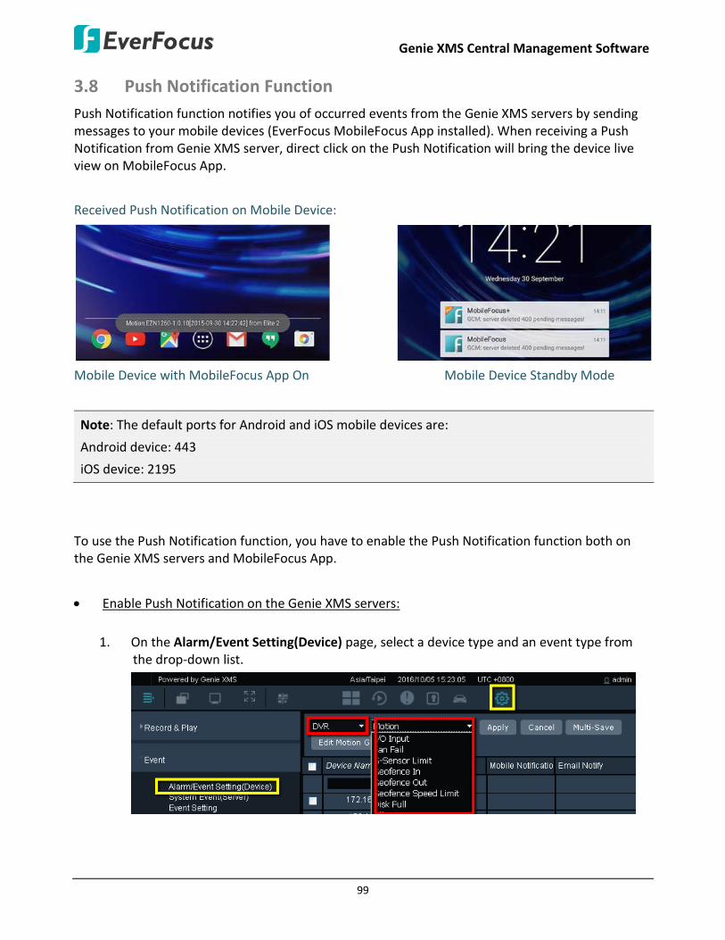
Genie XMS Central Management Software
99
3.8 Push Notification Function Push Notification function notifies you of occurred events from the Genie XMS servers by sending messages to your mobile devices (EverFocus MobileFocus App installed). When receiving a Push Notification from Genie XMS server, direct click on the Push Notification will bring the device live view on MobileFocus App.
Received Push Notification on Mobile Device:
Mobile Device with MobileFocus App On Mobile Device Standby Mode
Note: The default ports for Android and iOS mobile devices are:
Android device: 443
iOS device: 2195
To use the Push Notification function, you have to enable the Push Notification function both on the Genie XMS servers and MobileFocus App.
• Enable Push Notification on the Genie XMS servers:
1. On the Alarm/Event Setting(Device) page, select a device type and an event type from the drop-down list.

Genie XMS Central Management Software
100
Note: For DVR/NVR, to activate the event notification function on the Genie XMS Server, you have to configure the event and network alarm settings on the device end in advance:
For DVR/NVR:
1. Configure the event settings of your device (motion, video loss, disk full, and etc.). Ensure to enable (check) the Network Alarm function on each event setup page.
2. On the Alarm Server setting page, enter the IP address of the Genie XMS server in the
Server IP1 field. Select TCP from the Protocol drop-down and keep 1600 port.
3. On the LAN setting page, enter a network ID (numeric or alphabetic). The network ID
setup on the Device Maintain page of the Genie XMS server should match the one setup here. To avoid device conflicts, one network ID can only be assigned to one DVR/NVR. Click the Save button.

Genie XMS Central Management Software
101
For Mobile DVR:
1. To transfer alarm events, including Alarm, Motion, GPS Loss, and etc., from the mobile DVR to the system, you have to enable the Network Alarm and Send to Xfleet functions for the desired event types on the mobile DVR in advance. Click Save to save the setting.
2. To transfer data like GPS or G-Sensor data from the mobile DVR to the system, you have
to enable the Network Alarm function; and then configure the GPS and G-Sensor settings on the mobile DVR in advance.
• Enabling G-Sensor function:
Click G-Sensor Event to enable the G-sensor and network alarm function, and then setup the related G-sensor settings. Click the Save button to save the setting.
• Enabling GPS function:
Click GPS Event, enable Network Alarm and set up the GPS settings. Click Save.

Genie XMS Central Management Software
102
3. On the Xfleet setting page (Network < Xfleet). Input the IP address, Account and Password of the Xfleet system. Keep 80 port and click the Save button.
4. On the LAN setting page (Network < LAN), enter a network ID (numeric or alphabetic). The
network ID setup on the Device Maintain page of the Xfleet system should match the one setup here. To avoid device conflicts, one network ID can only be assigned to one mobile DVR. Click the Save button to save the setting.
2. Checked the Enable columns to enable the event notification function for the devices. Check the Mobile Notification columns for the selected event.
3. Click the Apply button to save the settings.

Genie XMS Central Management Software
103
• Enable Push Notification on MobileFocus App:
The below example is from an Android device. For more details about operating functions of Push Notification on MobileFocus App, please refer to the MobileFocus(Plus) User’s Manual.
1. Tap and hold a Genie XMS server, and this menu appears as below.
2. Tap Edit device to bring up the below page. Tap Receive Notification to turn ON the push
notification function. By default, the Receive Notification function is ON for any newly added Genie XMS servers.

Genie XMS Central Management Software
104
3. Tap Done and the message “Enable receive notification success.” will pop up.
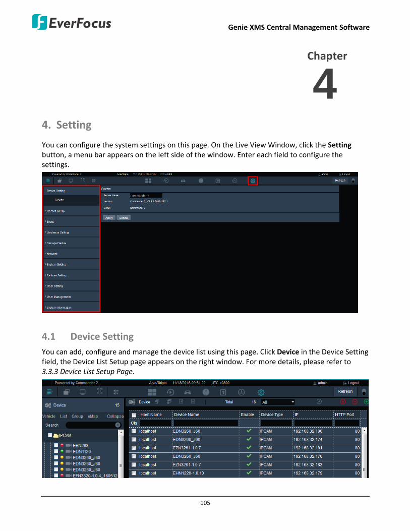
Genie XMS Central Management Software
105
4. Setting
You can configure the system settings on this page. On the Live View Window, click the Setting button, a menu bar appears on the left side of the window. Enter each field to configure the settings.
4.1 Device Setting You can add, configure and manage the device list using this page. Click Device in the Device Setting field, the Device List Setup page appears on the right window. For more details, please refer to 3.3.3 Device List Setup Page.
Chapter
4

Genie XMS Central Management Software
106
4.2 Record & Play You can configure the recording and playback settings in this field.
4.2.1 Built-In Calculator
You can use this calculator to calculator how much storage capacity you may need for a certain number of IP cameras with the setup bit rate and record time. Enter the bit rate, camera quantity and record time of the IP camera and then click the Apply button. The storage capacity will be displayed in the Data Size column.
4.2.2 Playback
You can configure the playback time for the Quick Playback function here. Enter the desired time for playing back the recording. Take the below image for example, if the current system clock time is 17:35:00, the start time for the playback recording will start from 17:34:00 (60 seconds ago from 17:35:00). To use the Quick Playback function, please refer to 3.5.1.3 Quick Playback.

Genie XMS Central Management Software
107
4.2.3 Holidays
You can optionally create the holidays and apply the recording schedule settings for the created holidays. Click the blank column to select a date, optionally check Repeat Annually, and then click the Apply button.
After creating the holidays, you can set up the holiday recording schedule to store the recordings to the system on the Schedule setting page (see 4.2.4 Schedule).
4.2.4 Schedule
The Schedule Recording is designed for IP cameras and RTSP devices. After the Schedule function is set up, the IP camera and RTSP device recordings will be stored in the Genie XMS server. You can then remotely play back the recordings (see 3.5.1 Remote Playback).
Normal + Event (Blue): This recording type button represents Continuous and Event recordings.
Event (Yellow): This recording type button represents Event recordings only.
No Record (Dark Gray): This recording type button represents No recording.
Note: For Event recordings, you have to configure the event settings in advance. On the Live View Window, click the Setting button and then click Event on the menu bar to enter the Event Setting page (see 4.3 Event).

Genie XMS Central Management Software
108
Related Device List: Click to display the devices connected to the system. Select the desired devices to apply the setup schedule.
Schedule Name List: Click to display the schedule list. Select a desired schedule and click Apply.
Add: Click to add a new schedule.
Apply: Click to apply the schedule to the system.
Cancel: Click to cancel the current setting.
To add a recording schedule to the Schedule Name List:
1. Select a recording type by clicking on the recording type buttons (Blue / Yellow / Dark Gray).
2. Move the cursor on a desired time square over the Schedule, click and drag the cursor to set up the time period on each day. The squares will be displayed in blue/yellow/dark gray to indicate which recording type has been applied to the time period.
3. Click the Add button and enter a name for the recording schedule.
4. The recording schedule should be listed in the Schedule Name List.
To rename or delete an added schedule from the Schedule Name List, select an added schedule from the list and then click the Rename / Remove button.

Genie XMS Central Management Software
109
To apply a recording schedule to the desired devices:
1. Click the Related Device List button, select the desired devices and then click the Save button.
2. Select a desired recording schedule from the Schedule Name List drop-down list and then click
the Apply button.
To activate the Schedule Recording function, on the Device Maintain page, make sure the Storage Device and Record to Server have been set up and enabled.
Note: If both of the “IP camera / RTSP device schedule recording” and “DVR / NVR auto backup” functions have been enabled on your Genie XMS server, please assign different Storage Device group to IP camera / RTSP device and DVR / NVR. For example, assign Storage Device A to IP camera and Storage Device B to DVR.

Genie XMS Central Management Software
110
4.2.5 Archive
You can archive the recordings form the system to your computer in AVI format and then use AVI-supported player to play back the recordings.
Start Date: Click to select a start date.
Start Time: Click to select a start time.
End Date: Click to select an end date.
End Time: Click to select an end time.
Prefix File Name: Enter a name for the archived file.
Stream Type: Click to select a stream type for the selected device.
Archive Format: Click to select a format for the archived file. The options include AVI, MP4 and AVR. Note that for remote archiving from DVR/NVR, only the AVR file format is supported.
Archive File Size: Click to select a limited file size for the archived recording.
Save Archive In: Click the Open File Path button to open the recording path.
Export: Click to start archiving the recording to the recording path.
Cancel: Click to cancel the archive process.
Related Device List: Click to display the device list to select the desired devices for archiving. For DVR/NVR, you can select specific channels from a DVR or NVR.

Genie XMS Central Management Software
111
To archive the recordings from the system to your computer for local playback:
1. On the Live View Window, click Setting, click Record & Play and click Archive.
2. Set up the start and end time, enter a name for the archived recording in the Prefix File Name
field, select a stream type, archive format and archive size. Select an archiving file path by clicking the Open File Path button.
3. Click the Related Device List button to select the desired cameras.
4. Click the Export button, the archiving status will be displayed on the bottom window. The archived recordings will be saved to the storage path.
5. You can use any AVI/MP4-supported player to play back the archived AVI/MP4 recordings. Or use EFPlayer or EF-Reader to play back the AVR recordings.

Genie XMS Central Management Software
112
Note: To archive the recordings from DVR, NVR and Mobile DVR in AVI/MP4 format, the Backup to Server function must be checked on the device Maintain page. If the option is unchecked, the recordings will be archived in AVR format (directly archived from the device HDD), and you have to use EverFocus’ players such as EFPlayer or EF-Reader to play back the recordings.
4.3 Event You can configure the event settings for devices and XMS systems, including Connection Lost, Motion Detection, Alarm Trigger or System Event for the connected devices. When an event occurs or an alarm is triggered, the pre-configured alarm actions, such as alarm pop-up, live view window pop-up, email, alarm sound or SOP notice, will be activated for notification.
Note: The pop-up notification windows will be displayed on the XMS window no matter on Live View, Playback or any page you are currently using. If you want to disable Live Stream Alarm Pop-up window on Live View or Playback View, check Disable Popup Windows on Live View or Disable Popup Windows on Playback View and click the Apply button (see 4.3.3 Event Setting).
4.3.1 Alarm/Event Setting (Device)
Before using the device event alarm function, you have to configure the device settings in advance. Select a device from the drop-down list to configure the settings.

Genie XMS Central Management Software
113
4.3.1.1Access Controller
This function is license required. Click Access Controller from the device type drop-down list. You can set up the live stream pop-up alarm for the access control events. For more details on Access Control, please refer to 5.2 Access Control.
Note: The pop-up notification windows will be displayed on the Genie XMS window no matter on Live View, Playback or any page you are currently using. If you want to disable Live Stream Alarm Pop-up window on Live View or Playback View, check Disable Popup Windows on Live View or Disable Popup Windows on Playback View and click the Apply button (see 4.3.3 Event Setting).
1. Select an event type from the drop-down list.
2. Checked the Enable column to enable the event notification function. Check the desired event
notifications for the selected event.
You can also click the Multi-Save button to apply the selected event notifications for all the devices on this page. Check the device boxes first and then click the Multi-Save button.

Genie XMS Central Management Software
114
Mobile Notification: When there is an event occurs on the Genie XMS server, Genie XMS server will send a notification to your mobile device (android / iOS). To set up the Push Notification function, please refer to 3.9 Push Notification Function for more details.
Snapshot: A snapshot will pop up on the Access Control Monitoring page (see 5.2 Access Control) when an event occurs.
Email Notify: An email notification will send to the pre-configured receiver (see 4.6.2 Email).
Alarm Popup: An alarm text will pop up on the top window.
Audio Alert: An alarm sound will be activated for alert notification. To set up an alarm sound, please refer to 4.3.4 Event Audio Setting.
Go to eMap Layer: The system will go to the eMap layer where the triggered camera is applied to (see 3.3.1.1 Go to eMap Layer).
SOP Window Popup: An SOP window will pop up displaying the event procedures to take. When this window pops up, you can check the procedures and enter the information of what actions you have done in the blank. Click the Save button to save the information. For this function to work, you have to click the SOP Setup button to edit an event procedure in advance.
3. Click the Apply button to save the settings.
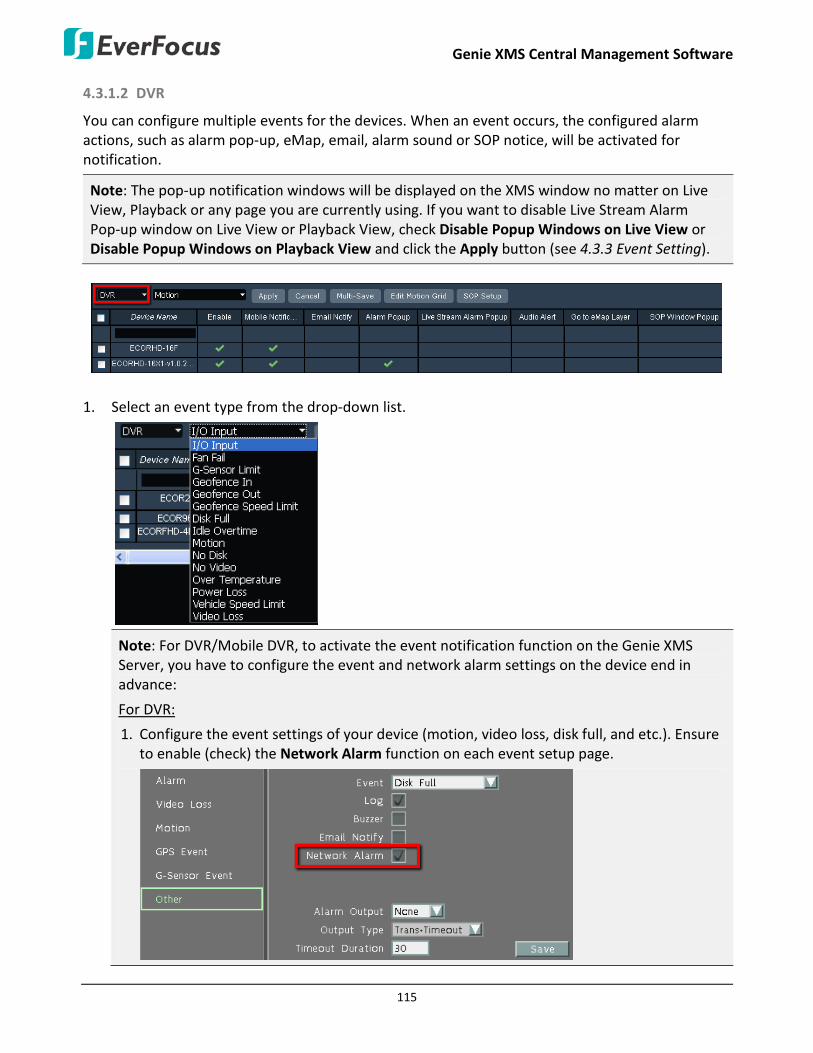
Genie XMS Central Management Software
115
4.3.1.2 DVR
You can configure multiple events for the devices. When an event occurs, the configured alarm actions, such as alarm pop-up, eMap, email, alarm sound or SOP notice, will be activated for notification.
Note: The pop-up notification windows will be displayed on the XMS window no matter on Live View, Playback or any page you are currently using. If you want to disable Live Stream Alarm Pop-up window on Live View or Playback View, check Disable Popup Windows on Live View or Disable Popup Windows on Playback View and click the Apply button (see 4.3.3 Event Setting).
1. Select an event type from the drop-down list.
Note: For DVR/Mobile DVR, to activate the event notification function on the Genie XMS Server, you have to configure the event and network alarm settings on the device end in advance:
For DVR:
1. Configure the event settings of your device (motion, video loss, disk full, and etc.). Ensure to enable (check) the Network Alarm function on each event setup page.

Genie XMS Central Management Software
116
2. On the Alarm Server setting page, enter the IP address of the Genie XMS server in the Server IP1 field. Select TCP from the Protocol drop-down and keep 1600 port.
3. On the LAN setting page, enter a network ID (numeric or alphabetic). The network ID
setup on the Device Maintain page of the Genie XMS server should match the one setup here. To avoid device conflicts, one network ID can only be assigned to one DVR/NVR. Click the Save button.
For Mobile DVR:
1. To transfer alarm events, including Alarm, Motion, GPS Loss, and etc., from the mobile DVR to the system, you have to enable the Network Alarm and Send to Xfleet functions for the desired event types on the mobile DVR in advance. Click Save to save the setting.

Genie XMS Central Management Software
117
2. To transfer data like GPS or G-Sensor data from the mobile DVR to the system, you have
to enable the Network Alarm function; and then configure the GPS and G-Sensor settings on the mobile DVR in advance.
• Enabling G-Sensor function:
Click G-Sensor Event to enable the G-sensor and network alarm function, and then setup the related G-sensor settings. Click the Save button to save the setting.
• Enabling GPS function:
Click GPS Event, enable Network Alarm and set up the GPS settings. Click Save.
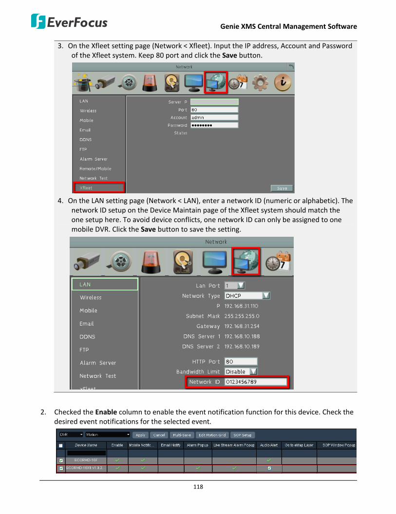
Genie XMS Central Management Software
118
3. On the Xfleet setting page (Network < Xfleet). Input the IP address, Account and Password of the Xfleet system. Keep 80 port and click the Save button.
4. On the LAN setting page (Network < LAN), enter a network ID (numeric or alphabetic). The
network ID setup on the Device Maintain page of the Xfleet system should match the one setup here. To avoid device conflicts, one network ID can only be assigned to one mobile DVR. Click the Save button to save the setting.
2. Checked the Enable column to enable the event notification function for this device. Check the desired event notifications for the selected event.

Genie XMS Central Management Software
119
You can also click the Multi-Save button to apply the selected event notifications for all the devices on this page. Check the device boxes first and then click the Multi-Save button.
Mobile Notification: When there is an event occurs on the Genie XMS server, Genie XMS server will send a notification to your mobile device (android / iOS). To set up the Push Notification function, please refer to 3.9 Push Notification Function for more details.
Email Notify: An email notification will send to the pre-configured receiver (see 4.6.2 Email).
Alarm Popup: An alarm text will pop up on the top window.
Audio Alert: An alarm sound will be activated for alert notification. To set up an alarm sound, please refer to 4.3.4 Event Audio Setting.
Go to eMap Layer: The system will go to the eMap layer where the triggered camera is applied to (see 3.3.1.1 Go to eMap Layer).
SOP Window Popup: An SOP window will pop up displaying the event procedures to take. When this window pops up, you can check the procedures and enter the information of what actions you have done in the blank. Click the Save button to save the information. The information will be displayed on the Event List (see 3.6 Event List). For this function to work, you have to click the SOP Setup button to edit an event procedure in advance.

Genie XMS Central Management Software
120
Event List (image below)
3. Click the Apply button to save the settings.
4.3.1.3 IPCam
You can configure multiple events for the devices. When an event occurs, the configured alarm actions, such as alarm pop-up, eMap, email, alarm sound or SOP notice, will be activated for notification.
Note: The pop-up notification windows will be displayed on the XMS window no matter on Live View, Playback or any page you are currently using. If you want to disable Live Stream Alarm Pop-up window on Live View or Playback View, check Disable Popup Windows on Live View or Disable Popup Windows on Playback View and click the Apply button (see 4.3.3 Event Setting).
1. Select an event type from the drop-down list.
Note:
1. If you select Motion, you have to configure the motion grid settings (see Step 3) in order to activate the Motion event function.
2. Currently, SD Card Status event is only applied to EverFocus EAN3126 and EPN4220 IP cameras.
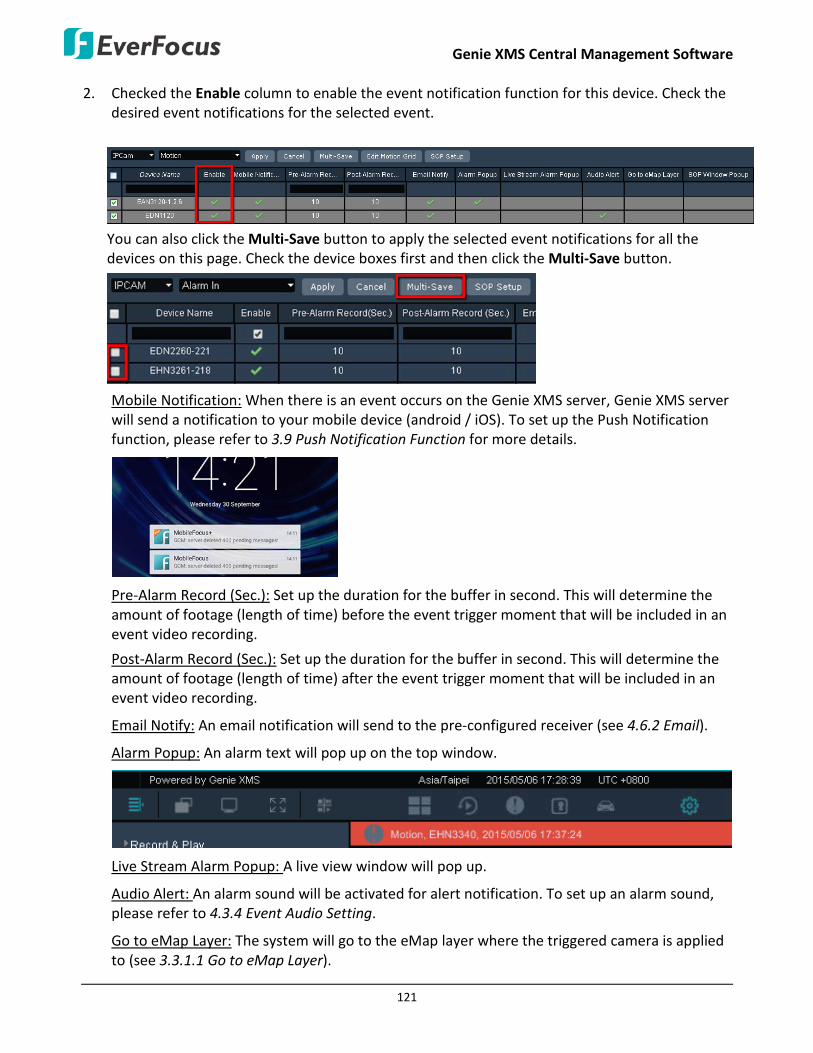
Genie XMS Central Management Software
121
2. Checked the Enable column to enable the event notification function for this device. Check the desired event notifications for the selected event.
You can also click the Multi-Save button to apply the selected event notifications for all the devices on this page. Check the device boxes first and then click the Multi-Save button.
Mobile Notification: When there is an event occurs on the Genie XMS server, Genie XMS server will send a notification to your mobile device (android / iOS). To set up the Push Notification function, please refer to 3.9 Push Notification Function for more details.
Pre-Alarm Record (Sec.): Set up the duration for the buffer in second. This will determine the amount of footage (length of time) before the event trigger moment that will be included in an event video recording.
Post-Alarm Record (Sec.): Set up the duration for the buffer in second. This will determine the amount of footage (length of time) after the event trigger moment that will be included in an event video recording.
Email Notify: An email notification will send to the pre-configured receiver (see 4.6.2 Email).
Alarm Popup: An alarm text will pop up on the top window.
Live Stream Alarm Popup: A live view window will pop up.
Audio Alert: An alarm sound will be activated for alert notification. To set up an alarm sound, please refer to 4.3.4 Event Audio Setting.
Go to eMap Layer: The system will go to the eMap layer where the triggered camera is applied to (see 3.3.1.1 Go to eMap Layer).

Genie XMS Central Management Software
122
SOP Window Popup: An SOP window will pop up displaying the event procedures to take. When this window pops up, you can check the procedures and enter the information of what actions you have done in the blank. Click the Save button to save the information. The information will be displayed on the Event List (see 3.6 Event List). For this function to work, you have to click the SOP Setup button to edit an event procedure in advance.
Event List (image below)
3. If you select Motion event from the event type drop-down, you have to configure the motion grid to activate the Motion event function.
a. Click the Edit Motion Grid button to call up the Edit Motion Grid window. You can only configure one motion detection zone for each IP camera.

Genie XMS Central Management Software
123
b. Select an IP camera by checking the box on the list. You can also select multiple IP cameras to apply the same motion grid setting to the selected IP cameras.
c. On the Edit Motion Grid window, click the Apply to All button to apply the motion detection function to the entire screen. You can also set up a motion area by using your mouse to drag an area.
d. Click the Sensitivity drop-down list to select the motion sensitivity for the motion area.
e. Click the Apply button to save the settings
4. Click the Apply button to save the settings.
4.3.1.4 NVR
You can configure multiple events for the devices. When an event occurs, the configured alarm actions, such as alarm pop-up, eMap, email, alarm sound or SOP notice, will be activated for notification.
Note: The pop-up notification windows will be displayed on the XMS window no matter on Live View, Playback or any page you are currently using. If you want to disable Live Stream Alarm Pop-up window on Live View or Playback View, check Disable Popup Windows on Live View or Disable Popup Windows on Playback View and click the Apply button (see 4.3.3 Event Setting).
1. Select an event type from the drop-down list.
Note: To activate the event notification function on the Genie XMS Server, you have to configure the event and network alarm settings on the device end in advance:
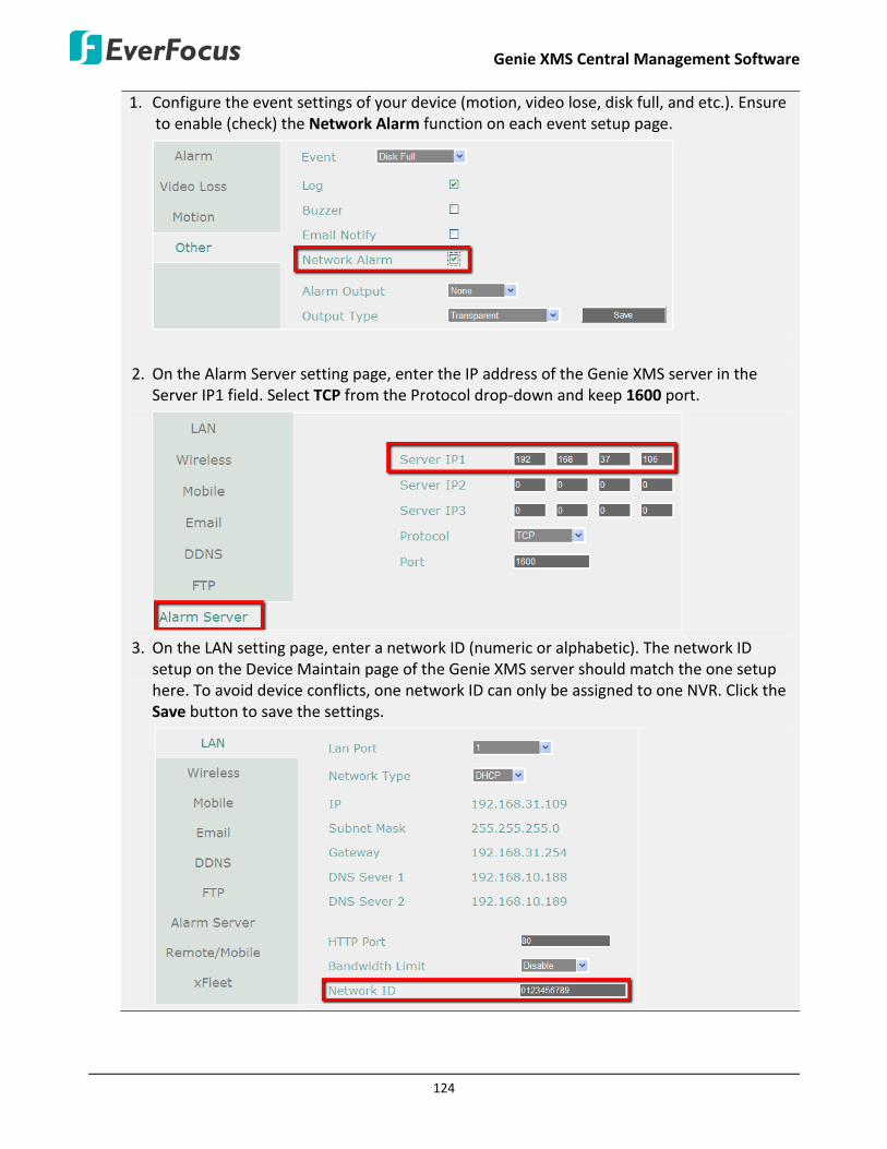
Genie XMS Central Management Software
124
1. Configure the event settings of your device (motion, video lose, disk full, and etc.). Ensure to enable (check) the Network Alarm function on each event setup page.
2. On the Alarm Server setting page, enter the IP address of the Genie XMS server in the Server IP1 field. Select TCP from the Protocol drop-down and keep 1600 port.
3. On the LAN setting page, enter a network ID (numeric or alphabetic). The network ID
setup on the Device Maintain page of the Genie XMS server should match the one setup here. To avoid device conflicts, one network ID can only be assigned to one NVR. Click the Save button to save the settings.

Genie XMS Central Management Software
125
2. Checked the Enable column to enable the event notification function for this device. Check the desired event notifications for the selected event.
You can also click the Multi-Save button to apply the selected event notifications for all the devices on this page. Check the device boxes first and then click the Multi-Save button.
Mobile Notification: When there is an event occurs on the Genie XMS server, Genie XMS server will send a notification to your mobile device (android / iOS). To set up the Push Notification function, please refer to 3.9 Push Notification Function for more details.
Email Notify: An email notification will send to the pre-configured receiver (see 4.4.2 Email).
Alarm Popup: An alarm text will pop up on the top window.
Audio Alert: An alarm sound will be activated for alert notification. To set up an alarm sound, please refer to 4.3.4 Event Audio Setting.
Go to eMap Layer: The system will go to the eMap layer where the triggered camera is applied to (see 3.3.1.1 Go to eMap Layer).
SOP Window Popup: An SOP window will pop up displaying the event procedures to take. When this window pops up, you can check the procedures and enter the information of what actions you have done in the blank. Click the Save button to save the information. The information will be displayed on the Event List (see 3.6 Event List). For this function to work, you have to click the SOP Setup button to edit an event procedure in advance.

Genie XMS Central Management Software
126
Event List (image below)
3. Click the Apply button to save the settings.
4.3.1.5 RTSP
You can configure multiple events for the devices. When an event occurs, the configured alarm actions, such as alarm pop-up, eMap, email, alarm sound or SOP notice, will be activated for notification.
Note: The pop-up notification windows will be displayed on the XMS window no matter on Live View, Playback or any page you are currently using. If you want to disable Live Stream Alarm Pop-up window on Live View or Playback View, check Disable Popup Windows on Live View or Disable Popup Windows on Playback View and click the Apply button (see 4.3.3 Event Setting).
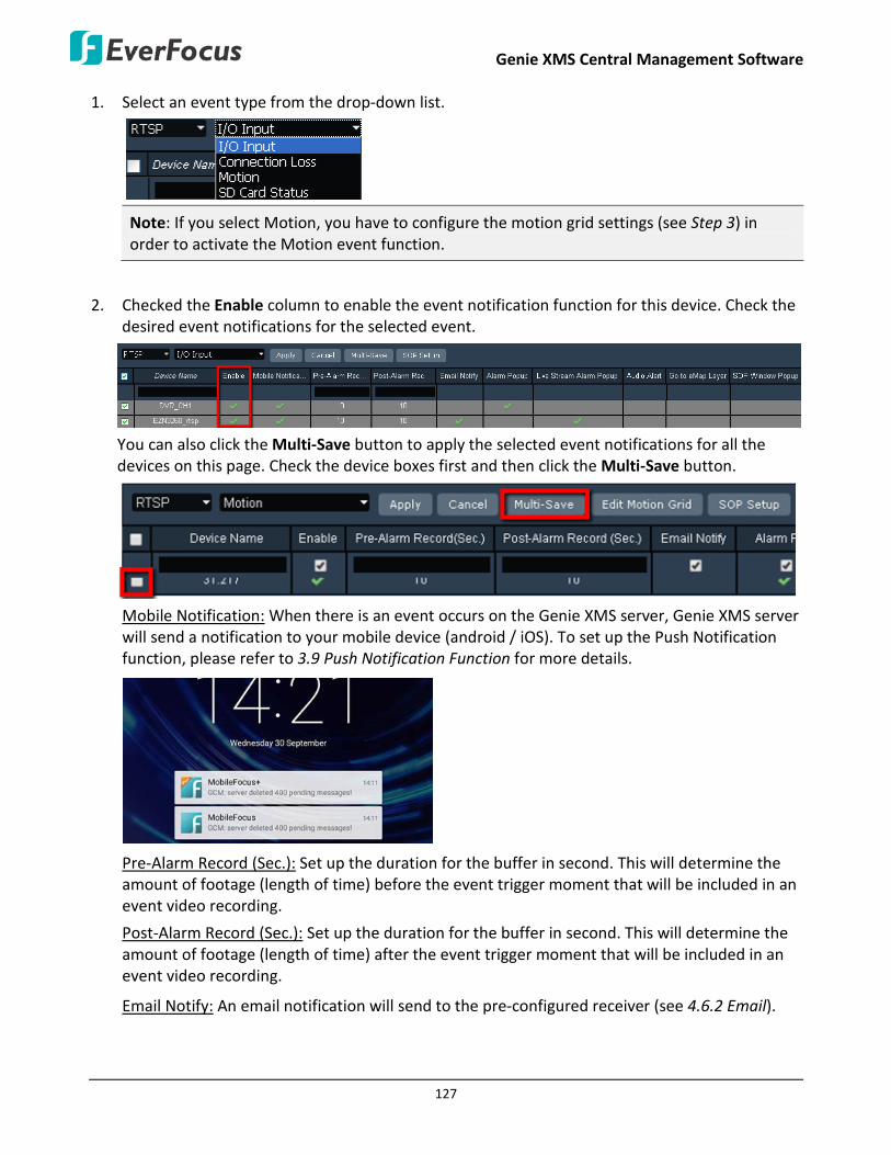
Genie XMS Central Management Software
127
1. Select an event type from the drop-down list.
Note: If you select Motion, you have to configure the motion grid settings (see Step 3) in order to activate the Motion event function.
2. Checked the Enable column to enable the event notification function for this device. Check the desired event notifications for the selected event.
You can also click the Multi-Save button to apply the selected event notifications for all the devices on this page. Check the device boxes first and then click the Multi-Save button.
Mobile Notification: When there is an event occurs on the Genie XMS server, Genie XMS server will send a notification to your mobile device (android / iOS). To set up the Push Notification function, please refer to 3.9 Push Notification Function for more details.
Pre-Alarm Record (Sec.): Set up the duration for the buffer in second. This will determine the amount of footage (length of time) before the event trigger moment that will be included in an event video recording.
Post-Alarm Record (Sec.): Set up the duration for the buffer in second. This will determine the amount of footage (length of time) after the event trigger moment that will be included in an event video recording.
Email Notify: An email notification will send to the pre-configured receiver (see 4.6.2 Email).

Genie XMS Central Management Software
128
Alarm Popup: An alarm text will pop up on the top window.
Live Stream Alarm Popup: A live view window will pop up.
Audio Alert: An alarm sound will be activated for alert notification. To set up an alarm sound, please refer to 4.3.4 Event Audio Setting.
Go to eMap Layer: The system will go to the eMap layer where the triggered camera is applied to (see 3.3.1.1 Go to eMap Layer).
SOP Window Popup: An SOP window will pop up displaying the event procedures to take. When this window pops up, you can check the procedures and enter the information of what actions you have done in the blank. Click the Save button to save the information. The information will be displayed on the Event List (see 3.6 Event List). For this function to work, you have to click the SOP Setup button to edit an event procedure in advance.
Event List (image below)
3. If you select Motion event from the event type drop-down, you have to configure the motion grid to activate the Motion event function.
a. Click the Edit Motion Grid button to call up the Edit Motion Grid window. You can only configure one motion detection zone for each IP camera.
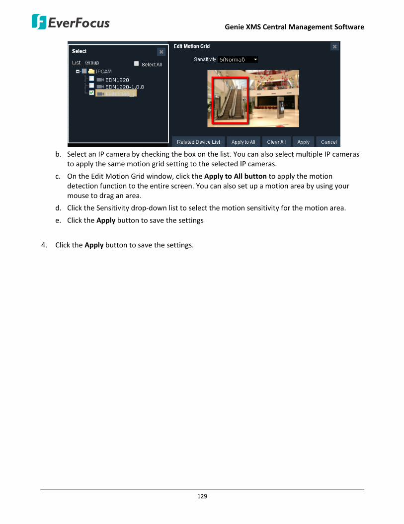
Genie XMS Central Management Software
129
b. Select an IP camera by checking the box on the list. You can also select multiple IP cameras
to apply the same motion grid setting to the selected IP cameras.
c. On the Edit Motion Grid window, click the Apply to All button to apply the motion detection function to the entire screen. You can also set up a motion area by using your mouse to drag an area.
d. Click the Sensitivity drop-down list to select the motion sensitivity for the motion area.
e. Click the Apply button to save the settings
4. Click the Apply button to save the settings.
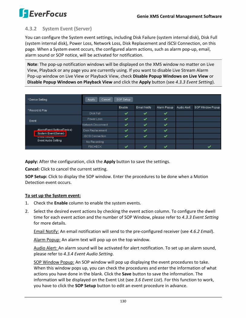
Genie XMS Central Management Software
130
4.3.2 System Event (Server)
You can configure the System event settings, including Disk Failure (system internal disk), Disk Full (system internal disk), Power Loss, Network Loss, Disk Replacement and iSCSI Connection, on this page. When a System event occurs, the configured alarm actions, such as alarm pop-up, email, alarm sound or SOP notice, will be activated for notification.
Note: The pop-up notification windows will be displayed on the XMS window no matter on Live View, Playback or any page you are currently using. If you want to disable Live Stream Alarm Pop-up window on Live View or Playback View, check Disable Popup Windows on Live View or Disable Popup Windows on Playback View and click the Apply button (see 4.3.3 Event Setting).
Apply: After the configuration, click the Apply button to save the settings.
Cancel: Click to cancel the current setting.
SOP Setup: Click to display the SOP window. Enter the procedures to be done when a Motion Detection event occurs.
To set up the System event:
1. Check the Enable column to enable the system events.
2. Select the desired event actions by checking the event action column. To configure the dwell time for each event action and the number of SOP Window, please refer to 4.3.3 Event Setting for more details.
Email Notify: An email notification will send to the pre-configured receiver (see 4.6.2 Email).
Alarm Popup: An alarm text will pop up on the top window.
Audio Alert: An alarm sound will be activated for alert notification. To set up an alarm sound, please refer to 4.3.4 Event Audio Setting.
SOP Window Popup: An SOP window will pop up displaying the event procedures to take. When this window pops up, you can check the procedures and enter the information of what actions you have done in the blank. Click the Save button to save the information. The information will be displayed on the Event List (see 3.6 Event List). For this function to work, you have to click the SOP Setup button to edit an event procedure in advance.
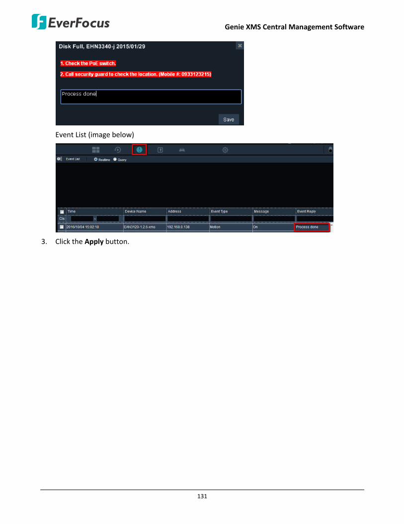
Genie XMS Central Management Software
131
Event List (image below)
3. Click the Apply button.

Genie XMS Central Management Software
132
4.3.3 Event Setting
You can configure the dwell time for each event action and the number of SOP Window; you can also enable / disable the Live Stream Alarm Pop-up window on Live View / Playback View. If you configure the auto close time to be zero “0”, the pop-up notification will be continuously displayed. Click the Apply button to save the settings.
Motion Interval Time (10-300 sec.)
Users can set up Motion Interval Time to limit the number of event action pop-up times (alarm pop-up, live pop-up, etc.) when a motion event occurs. This is to avoid numerous event pop-ups from the same event. For example, if you set up Motion Interval Time as 10 seconds, when the camera detects a person who is wiping a window (say if the person has been doing it for 30 seconds), the Genie XMS will pop-up alarm every 10 seconds.
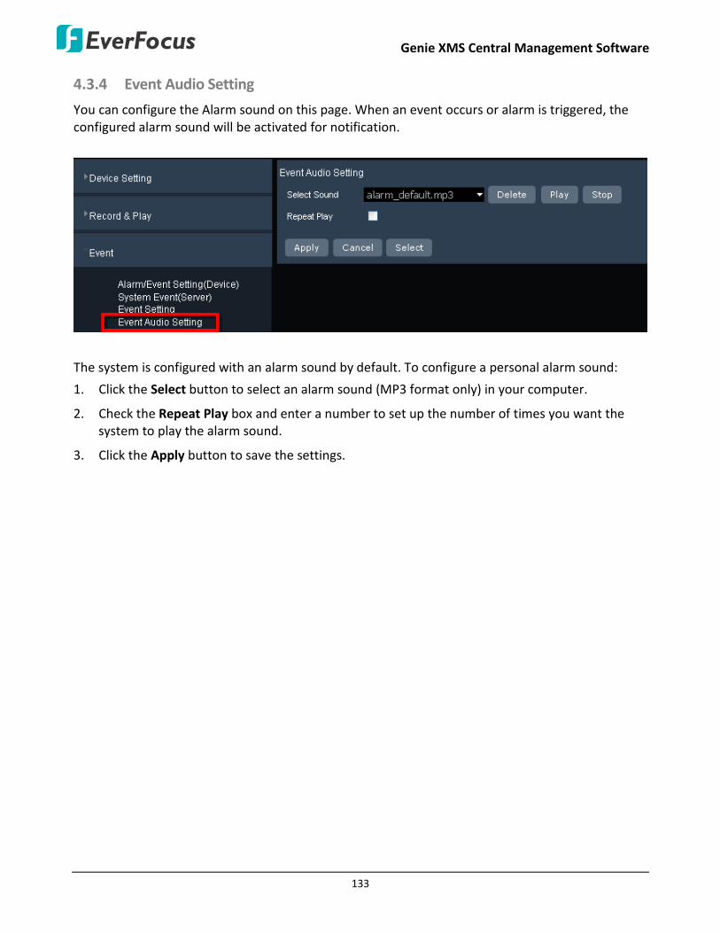
Genie XMS Central Management Software
133
4.3.4 Event Audio Setting
You can configure the Alarm sound on this page. When an event occurs or alarm is triggered, the configured alarm sound will be activated for notification.
The system is configured with an alarm sound by default. To configure a personal alarm sound:
1. Click the Select button to select an alarm sound (MP3 format only) in your computer.
2. Check the Repeat Play box and enter a number to set up the number of times you want the system to play the alarm sound.
3. Click the Apply button to save the settings.

Genie XMS Central Management Software
134
4.4 Geofence Setting After setting up the Geofences, you can optionally set up a Geofence Schedule. When a vehicle enters or exits the geofence(s) at specific time, the related alarm will be triggered.
For more details about Geofence Schedule, please refer to 2.3.2.2 Geofence Schedule.
4.4.1 Geofence Schedule Profile
You can configure multiple Geofence Schedule on this page. To configure a Geofence Schedule:
1. Configure geofence(s) in advance (see To configure a Geofence in 2.3.2.1 Geofence List).
2. On the Main Page, click the Setting button to display the left-side bar. Click Geofence Setting and Geofence Schedule Profile to enter the Geofence Schedule setting page.
3. To add a schedule in the Geofence Schedule List, click the Add button and the Geofence
Schedule Profile window appears.
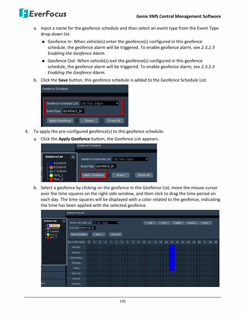
Genie XMS Central Management Software
135
a. Input a name for the geofence schedule and then select an event type from the Event Type drop-down list.
Geofence In: When vehicle(s) enter the geofence(s) configured in this geofence schedule, the geofence alarm will be triggered. To enable geofence alarm, see 2.3.2.3 Enabling the Geofence Alarm.
Geofence Out: When vehicle(s) exit the geofence(s) configured in this geofence schedule, the geofence alarm will be triggered. To enable geofence alarm, see 2.3.2.3 Enabling the Geofence Alarm.
b. Click the Save button, this geofence schedule is added to the Geofence Schedule List.
4. To apply the pre-configured geofence(s) to this geofence schedule:
a. Click the Apply Geofence button, the Geofence List appears.
b. Select a geofence by clicking on the geofence in the Geofence List, move the mouse cursor over the time squares on the right-side window, and then click to drag the time period on each day. The time squares will be displayed with a color related to the geofence, indicating the time has been applied with the selected geofence.

Genie XMS Central Management Software
136
c. Repeat the above step to apply other geofence(s) to the schedule. You can add a maximum of 5 geofence(s) to the same time square.
Erase: Click the Erase button and then move your mouse cursor over the configured time squares and drag the time period to be erased.
Erase All: Click the Erase All button to erase all geofence(s) configured on the schedule.
d. After the configuration, click the Apply button to save the setting. A “Success” message
appears on the bottom-left corner indicating this Geofence Schedule has been set up.
Note: You can optionally create holidays and apply the Geofence Schedule for the created holidays. To create holidays, please refer to 3.1.3 Holidays.

Genie XMS Central Management Software
137
5. To apply the desired vehicles to the Geofence Schedule, click the Apply To Vehicle button to bring up the Vehicle List window, check the checkboxes of the desire vehicles and then click the Save button on the Vehicle List window.
Note:
1. One vehicle can only be applied to one Geofence Schedule.
2. If a vehicle has been applied to both of a Geofence In/Out event or a Geofence Schedule event, the priority goes to Geofence Schedule event. For example, if vehicle A has been applied to both of the Geofence A (configured with a geofence in event) and a Geofence Schedule (applied with Geofence A with geofence out event), when vehicle A enters Geofence A, only the geofence out alarm of the Geofence Schedule will be triggered.
6. Repeat Step 3 and Step 4 to add multiple Geofence Schedules to the Geofence Schedule List.

Genie XMS Central Management Software
138
To edit a Geofence Schedule:
Select a Geofence Schedule from the Geofence Schedule List drop-down and then click the Edit button.
To edit the Name and Event Type, edit the Name and Event Type in the Geofence Schedule
Profile window and then click Save to save the edition. Click the Apply button to save the settings.
To edit the time squares, click the Apply Geofence and then re-configure the schedule on the time squares. Click the Apply button to save the settings.
To edit the vehicles, click the Apply to Vehicle button to apply the desired vehicles. Click the Apply button to save the settings.
To delete a Geofence Schedule:
Select a Geofence Schedule from the Geofence Schedule List drop-down and then click the Delete button.
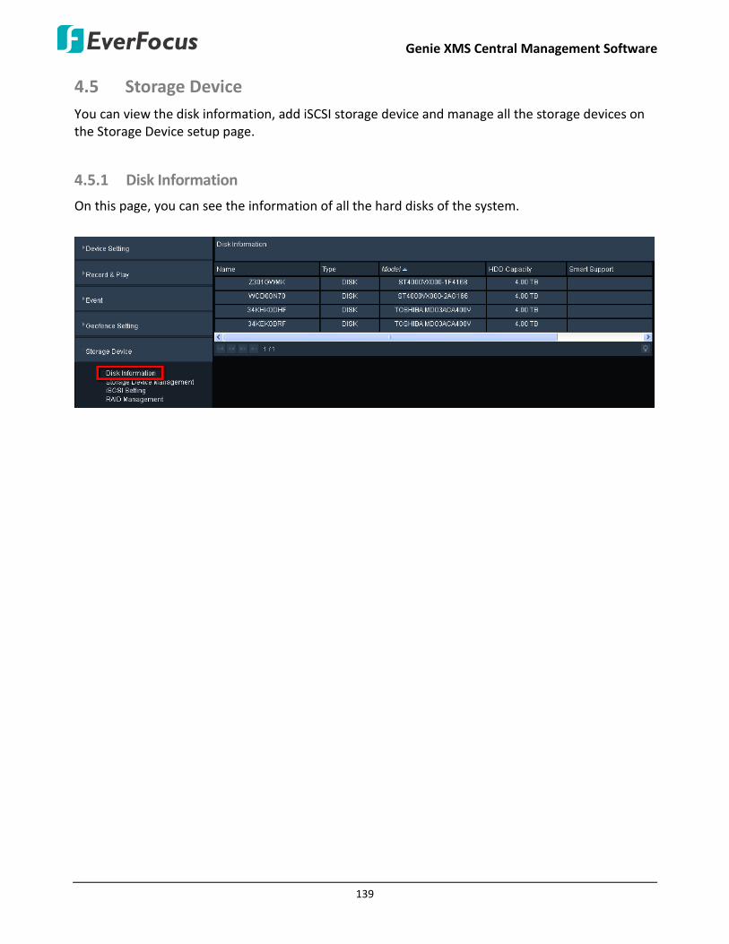
Genie XMS Central Management Software
139
4.5 Storage Device You can view the disk information, add iSCSI storage device and manage all the storage devices on the Storage Device setup page.
4.5.1 Disk Information
On this page, you can see the information of all the hard disks of the system.

Genie XMS Central Management Software
140
4.5.2 Storage Device Management
You can manage all the storage devices on this page.
On this page, all the hard disks including the on-system hard disks, the added iSCSI storage devices (see 4.4.3 iSCSI Setting) will be displayed on the top. You can group the hard disks for management purpose.
Click Format, the following message pops-up. Click Confirm to format the HDD for the first time added HDD. (WARNING: Clicking Format will effectively ERASE the ENTIRE hard disk! Please click Export to export the data from the HDD before clicking the Confirm button.)

Genie XMS Central Management Software
141
Note: The server will detect all the HDDs when entering the Storage Device Management page or when establishing Storage Groups. Once the detection process is done, the serial number of the HDDs will be displayed. However, if the server could not detect the serial number of the HDDs, the “Not Available” wording will be displayed and a message would pop-up to inform users to remove the “Not Available” HDDs from the storage group. The message will stop popping-up only when all the “Not Available” HDDS have been removed from all the storage groups. The “Not Available” HDDs are not able to record files.

Genie XMS Central Management Software
142
To create a new group:
To enable the recording function, you have to assign the hard disks to a group first.
1. By default, there is a new group created in the Storage Device Group Management field. Type a name in the Group column. You can optionally add another group by clicking the Add button.
2. Drag and drop the disks from the Unused Group to the newly created group. Note that one disk can only be added to one group.
3. Configure the group settings in the below column.
Auto Erase Recording (Days): The disks of the group will be automatically overwritten when the entered number of days has been reached. For example, if you set 5 days, the disks of the group will be overwritten at the beginning of day 6. To disable the function, enter zero “0” in the column.
Overwrite: Check the box to overwrite the disks of the group when the capacity is used up to 99%. To disable the function, uncheck the column.
4. Click the Apply button to save the settings. You can also see this group in the Storage Device drop-down list on the maintain page of the IP camera / NVR / DVR.

Genie XMS Central Management Software
143
To save multiple recordings from IP cameras and RTSP device to a disk group:
1. Click the Related Device List button, the related device list window pops up.
Note: If both of the “IP camera / RTSP device schedule recording” and “DVR / NVR auto backup” functions have been enabled on your Genie XMS server, please assign different Storage Device group to IP camera / RTSP device and DVR / NVR. For example, assign Storage Device A to IP camera and Storage Device B to DVR.
2. Select a disk group from the drop-down list beside the Related Device List button.
3. Select the devices in the related device list window and then click the Save button.

Genie XMS Central Management Software
144
You can also change the storage device for each device on its Maintain page:
1. On the Live View Window, click Setting to bring up the left-side setting menu. Click Device in the Device Setting field, the Device List Setup page appears on the right window.
2. Double-click a device to display its Maintain page, and then select a group from the Storage Device drop-down list.
Note: If both of the “IP camera / RTSP device schedule recording” and “DVR / NVR auto backup” functions have been enabled on your Genie XMS server, please assign different Storage Device group to IP camera / RTSP device and DVR / NVR. For example, assign Storage Device A to IP camera and Storage Device B to DVR.
3. Click the Save button to save the settings. The recordings of this device will be stored to the assigned group.
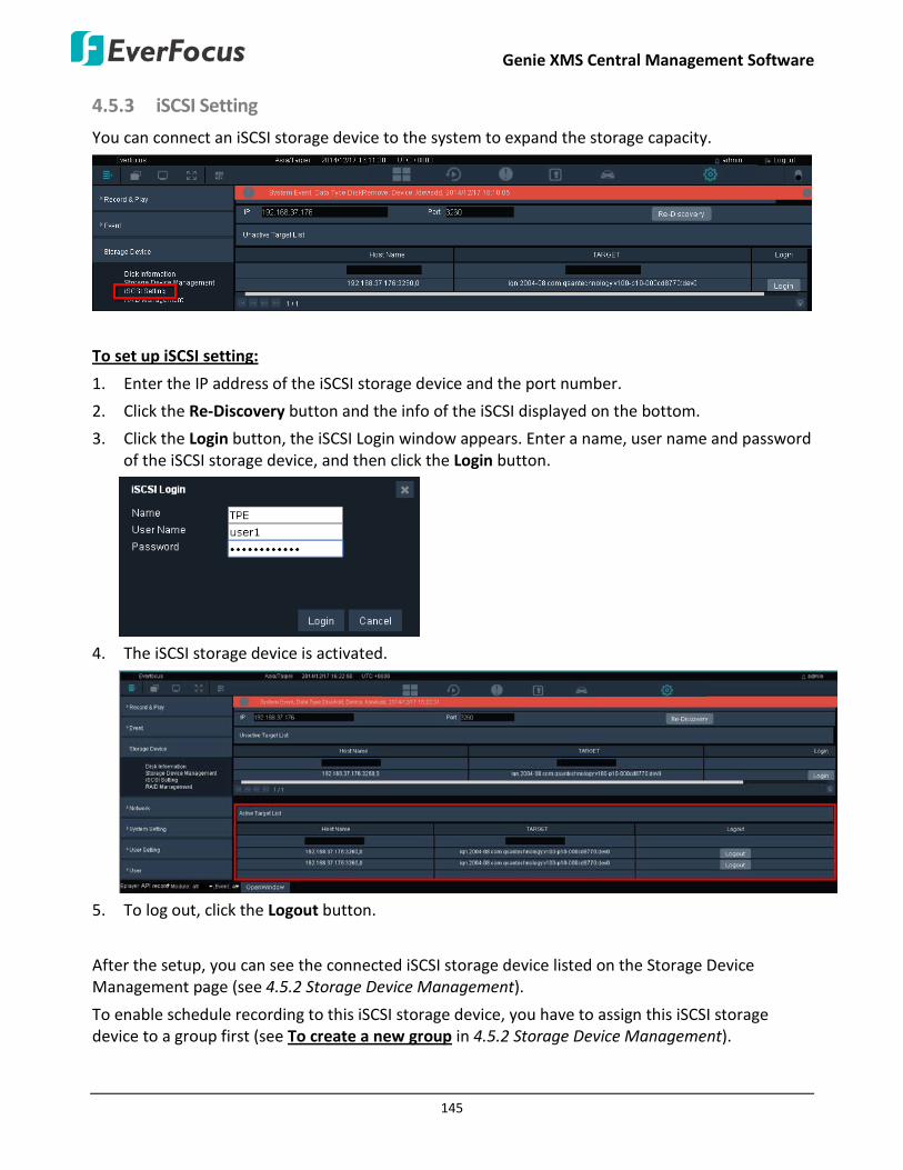
Genie XMS Central Management Software
145
4.5.3 iSCSI Setting
You can connect an iSCSI storage device to the system to expand the storage capacity.
To set up iSCSI setting:
1. Enter the IP address of the iSCSI storage device and the port number.
2. Click the Re-Discovery button and the info of the iSCSI displayed on the bottom.
3. Click the Login button, the iSCSI Login window appears. Enter a name, user name and password of the iSCSI storage device, and then click the Login button.
4. The iSCSI storage device is activated.
5. To log out, click the Logout button.
After the setup, you can see the connected iSCSI storage device listed on the Storage Device Management page (see 4.5.2 Storage Device Management).
To enable schedule recording to this iSCSI storage device, you have to assign this iSCSI storage device to a group first (see To create a new group in 4.5.2 Storage Device Management).

Genie XMS Central Management Software
146
4.6 Network On the left-side menu bar, click Network. You can set up the system’s network, email and DDNS settings or to test the network connectivity between the system and other LAN or WAN nodes in this menu.
4.6.1 Network Setting
On the left-side menu bar, click Network and then click Network Setting. According to your network environment, select Static IP, DHCP or PPPoE to configure an IP address to the system.
【General】
DNS Server 1: Displays the primary DNS server for your network. If DHCP is selected and an internet connection is available, this value should be assigned automatically. This field must have a valid DNS address in order to use the DDNS feature.
DNS Server 2: This field shows the secondary DNS server for your network.
DNS Server 3: This field shows the third DNS server for your network.
Default Gateway Network Card: Select LAN 1 or LAN 2 which is configured and used for a WAN connection.
HTTP Port: Enter the Http Port number of the system.
RTSP Port: Enter the RTSP port number of the system.
Archive Port: Enter the Archive port number of the system.
Forward Port Range: Enter a range for the forward port numbers.

Genie XMS Central Management Software
147
【LAN 1 / 2】
You can either set up a static IP or enable DHCP for LAN 1 / LAN 2.
IPv4 address: Displays the current IPv4 Address. A static IP address must be set manually. If DHCP is enabled, this value will be assigned automatically.
IPv4 Mask: Displays the subnet mask for your network so the system will be recognized within the network. If DHCP is enabled, this value will be assigned automatically.
IPv4 DHCP: Check to enable DHCP function, and then the DHCP server in LAN will automatically assign an IP configuration for the network connection.
Gateway: Displays the gateway on your network for the system to use when communicating with any devices not on the local network. If DHCP is enabled, this value will be assigned automatically.
IPv6 address: Displays the current IPv6 Address. A static IP address must be set manually. If DHCP is enabled, this value will be assigned automatically.
MAC: Displays the MAC address of LAN 1 / LAN2. This option cannot be changed.
【PPPoE】
You can also set up PPPoE for LAN 1 or LAN 2.

Genie XMS Central Management Software
148
Enable: Check to enable PPPoE.
User Name: Input the account user name. Contact your ISP for the details.
Password: Input the password. Contact your ISP for the details.
Default PPPoE Network Card: Select LAN 1 or LAN 2 to use PPPoE.
IPv4 Address: Displays the IPv4 address after a successful setup.
【Service】
If you forget the IP address of the system, you can use this IPv4 address to access to the system from a remote site.
IPv4 address: This is for users who forget the IP address of the system can still access to the system using this address. However, you will need to change the IP address of your computer to keep it in the same LAN of this IPv4 address.
For example, the default IPv4 address is 10.10.10.10, and then you can set a static IP address of 10.10.10.9 for your computer so that you can successfully enter the system by entering this IP of 10.10.10.10 into a browser.
IPv4 Mask: Displays the subnet mask for your network so the system will be recognized within the network.
MAC: Displays the MAC address. This option cannot be changed.

Genie XMS Central Management Software
149
4.6.2 Email
On the left-side menu bar, click Network and then click Email. You can configure the Email settings for the system to send Email alert when an event occurs.
SMTP Server: Assign the SMTP (e-mail) server’s name. Note that for more reliable email service, use the server’s IP address.
SMTP Port: Assign the port number used by the SMTP server.
Authentication: Check this box if the SMTP server requires authentication (user name / password).
User Name: Input the login user name if the SMTP server requires authentication.
Password: Input the password if the SMTP server requires authentication.
SSL: Check the box if mail server needs communication to be encrypted by SSL.
Receiver’s Email: Input the e-mail address that event messages are sent to. You can add multiple email addresses separated by a semicolon ”;” ([email protected];[email protected]).
Sender Email: Input the e-mail address of the sender (the system). Sender’s e-mail address has to match the user name and password above.
Connection Timeout (Sec.): Set up a duration time for the XMS server to stop connecting the mail server once the connection time reached the setup duration.
Socket Timeout (Sec.): Set up a duration time for the XMS server to stop sending emails once the sending time reached the setup duration.

Genie XMS Central Management Software
150
4.6.3 DDNS
On the left-side menu bar, click Network and then click Email. DDNS (Dynamic Domain Name System) is a service used to map a domain name to the dynamic IP address of a network device. You can set up the DDNS service for remote access to the system. 【EverFocus DDNS】
DDNS Service: Select EverfocusDDNS from the drop-down list.
Host Name: Input the desired name for the host. Note that the name of the host cannot include a space, underline or any special characters particularly _~ ! @ # $ % ^ & * ( ) + < > " ; : . ,
Note: You can go to http://www.everfocusddns.com to check if the DDNS name you desired is available or not.
【www.dyndns.org】
DDNS Service: Select www.dyndns.org from the drop-down list.
Host name: Host name created through the dyndns account.
User name: User name of the dyndns account.
Password: Password of the dyndns account.

Genie XMS Central Management Software
151
Setup Steps:
1. Apply for a host name from www.dyndns.org.
2. Make sure that the DNS Server 1 is set up correctly or the DDNS will not work.
3. Select www.dyndns.org from the DDNS Service drop-down list.
4. Enter the host name in the Host Name field. Note that the name of the system cannot include a space, underline or any special characters particularly _~ ! @ # $ % ^ & * ( ) + < > " ; : . , _
5. Enter the User Name / Password of the dyndns account.
6. The setting is complete. And you should now be able to remotely connect the system by typing the name you created into the address bar. Example: http://hostname.dyndns.com.
Note: If you are connecting through a router, make sure that you have opened up all the required network ports in the “Port Forwarding” section of your router’s setup options. The default port of the system is 80. To set up Port Forwarding, please consult the manual of the router.
4.6.4 Network Test
On the left-side menu bar, click Network and then click Network Test. This function is useful in diagnosing connectivity problems by obtaining responses from nodes progressively farther along the network. Enter an IP address to verify basic network connectivity between the system and other LAN or WAN nodes, and then click the Test button.

Genie XMS Central Management Software
152
4.7 System Setting On the left-side menu bar, click System Setting. You can set up general settings for the system in this menu.
4.7.1 Time Zone
On the left-side menu bar, click System Setting and then click Time Zone. You can set up the time zone and country where the system server is located.
1. Select a time zone, or click on the map to select the time zone.
2. Select the country, or click on the map to select the country.
3. You can also click Auto Detection for the system to automatically detect the time zone and country. Then, click Share Location when the location permission request pops up.
4. Click Apply to save the setting.

Genie XMS Central Management Software
153
4.7.2 Date / Time
On the left-side menu bar, click System Setting and then click Date/Time. Enter the current date and time, and then click the Apply button to save the settings.
Date: Click to bring up the on-screen keyboard to set up the date.
Time: Click to bring up the on-screen clock to set up the time.
Date Format: Select a date format from the drop-down list.
NTP: Check to enable and display the NTP time synchronization setting.
NTP Server: Select a time server address that the system uses for time synchronization.
NTP Update Interval: The frequency that the system automatically updates the time via the NTP server. Select Hourly, Daily, Weekly or Monthly.
Port: The system will automatically set up the port number.
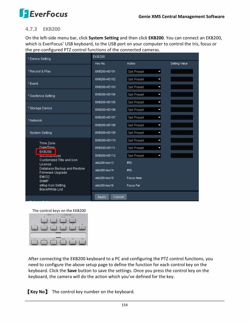
Genie XMS Central Management Software
154
4.7.3 EKB200
On the left-side menu bar, click System Setting and then click EKB200. You can connect an EKB200, which is EverFocus’ USB keyboard, to the USB port on your computer to control the Iris, focus or the pre-configured PTZ control functions of the connected cameras.
The control keys on the EKB200
After connecting the EKB200 keyboard to a PC and configuring the PTZ control functions, you need to configure the above setup page to define the function for each control key on the keyboard. Click the Save button to save the settings. Once you press the control key on the keyboard, the camera will do the action which you’ve defined for the key.
【Key No】 The control key number on the keyboard.

Genie XMS Central Management Software
155
【Action】 Select an item from the drop-down list to define the function for each key on the keyboard.
Set Preset: You can use the joystick on the keyboard to select a position and then press this key to save the position as the Preset Position.
Go to Preset: Press this key to let the camera go to the Preset Position number specified in the Value column.
Go to Home: Press this key and the camera will go to the Preset Position 1. Clear Preset: Press this key to clear the Preset Position number specified in the Value column. Run Auto Pan: Press this key to start the AutoPan number specified in the Value column. Stop Auto Pan: Press this key to stop the AutoPan number specified in the Value column. Tour Run: Press this key to start running the Tour number specified in the Value column. Tour Stop: Press this key to stop running the Tour number specified in the Value column. Pattern Run: Press this key to start running the Pattern number specified in the Value
column. Pattern Stop: Press this key to stop running the Pattern number specified in the Value
column. Set Auto Tracking: Press this key to switch On / Off the Auto-Tracking function. Toggle Full Screen: Press this key to toggle between the full screen and current screen.
【Setting Value】 Type in the number for the selected Action item. For example, selecting Go to Preset from the Action drop-down list and typing in 2 in the Value column represents the Preset Position 2.
To activate the EKB200 keyboard on the PTZ Live View page, please click PTZ Control on the left column, and then the PTZ control panel will display. Click Connect EKB200 to activate it, and then you can control the PTZ camera over the EKB200 keyboard.

Genie XMS Central Management Software
156
4.7.4 Miscellaneous
On the left-side menu bar, click System Setting and then click Miscellaneous.
Auto Refresh Daily on Live Page 03:00
Reboot: Click Apply to enable restarting the system. Shutdown: Click Apply if you need to turn off the system server. Load Factory Default: Click Apply to restore the system to factory default settings.
Console Log Window: This is just for debug use only. Check the box and the button will display at the bottom of the browser. Click it to open the console log window.
Adjustable UI: This function allows users to adjust the user interface in the Setting section. You can drag and drop the setting options to change their order on the interface.
System Log and Event Reserve Day(s) 1~365: Enter a specific days for the system to reserve the system log.
Displaying I-frame only when CPU usage of client PC reaches this percentage: Check the box to enable the function and then input a CPU percentage. When CPU usage of the system reaches the setup percentage, the system will automatically adjust the streaming to i-frames in order to lower down the CPU loading.
Google Maps API Key: Input the API Key applied from Google to display Google Maps on Xfleet Management Page. Xfleet function is license required.
Auto Refresh Daily on Live Page: Set up a time to refresh the Live Page automatically per day.

Genie XMS Central Management Software
157
4.7.5 Customized Title and Icon
On the left-side menu bar, click System Setting and then click Customized Title and Icon.
Title: Enter a title for the browser window.
Header: You can change the name to be displayed on the header of the website.
Upload Icon: You can change the icon that browsers display next to a page's title on a browser tab. Please use the icon image in “.ico” file format.
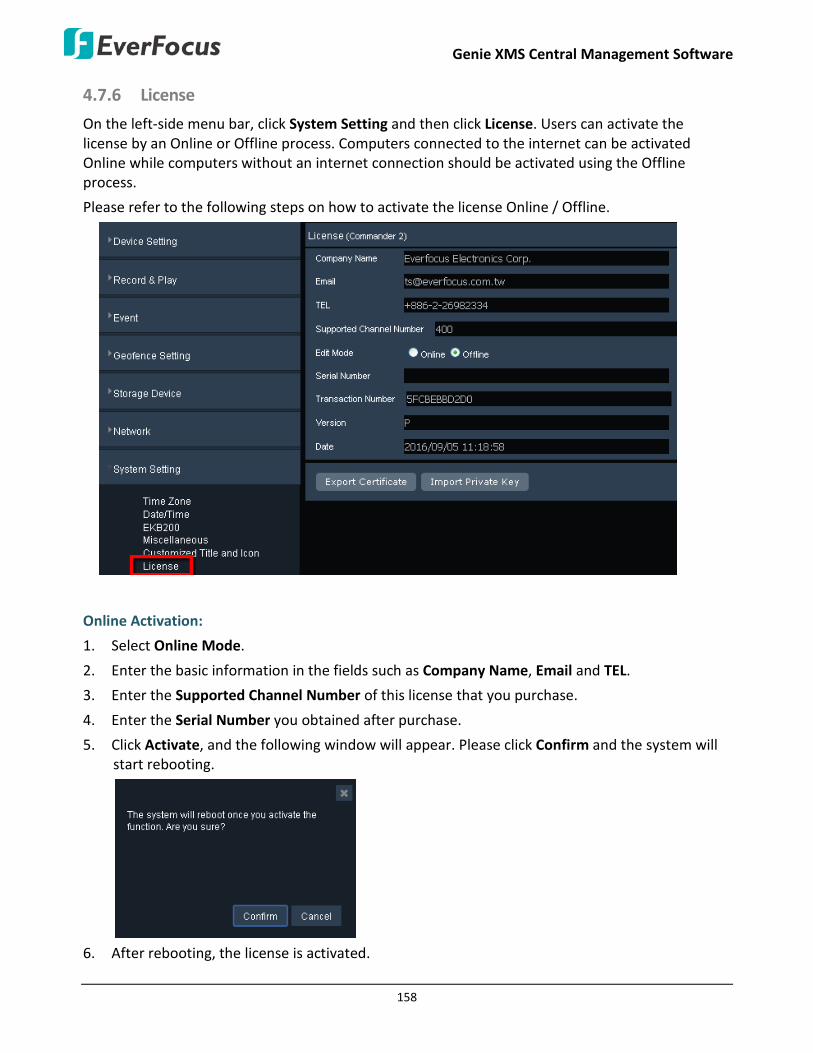
Genie XMS Central Management Software
158
4.7.6 License
On the left-side menu bar, click System Setting and then click License. Users can activate the license by an Online or Offline process. Computers connected to the internet can be activated Online while computers without an internet connection should be activated using the Offline process.
Please refer to the following steps on how to activate the license Online / Offline.
Online Activation:
1. Select Online Mode.
2. Enter the basic information in the fields such as Company Name, Email and TEL.
3. Enter the Supported Channel Number of this license that you purchase.
4. Enter the Serial Number you obtained after purchase.
5. Click Activate, and the following window will appear. Please click Confirm and the system will start rebooting.
6. After rebooting, the license is activated.
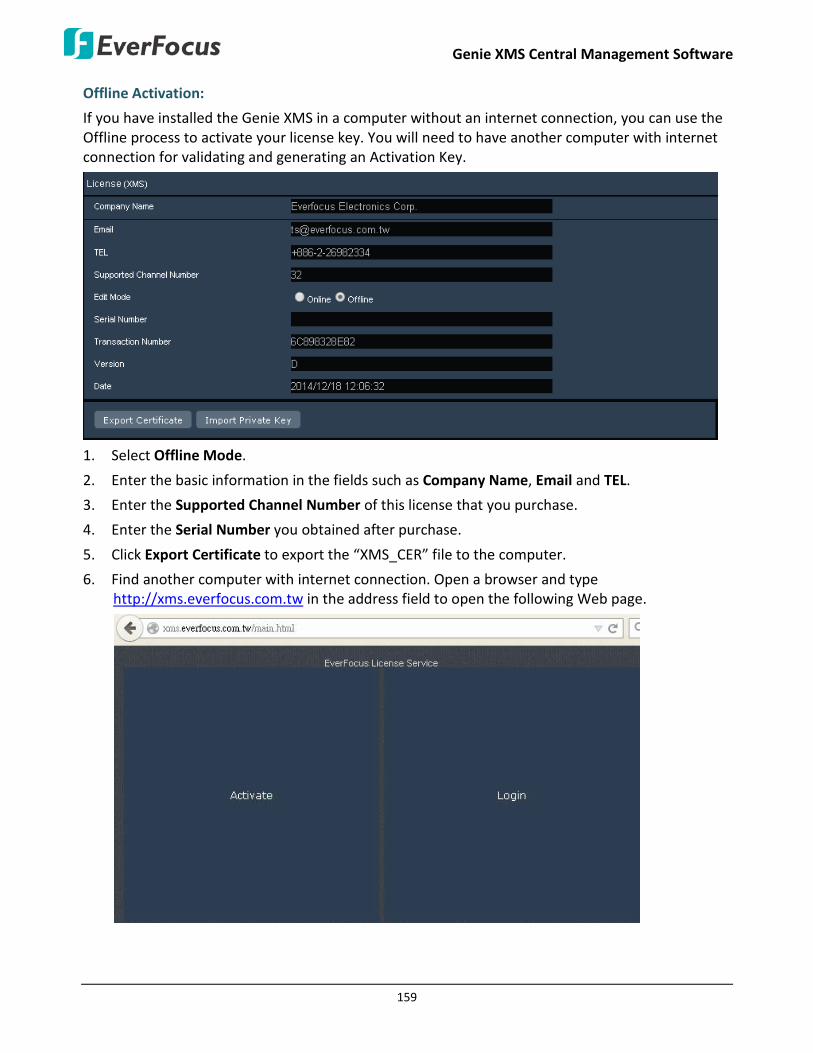
Genie XMS Central Management Software
159
Offline Activation:
If you have installed the Genie XMS in a computer without an internet connection, you can use the Offline process to activate your license key. You will need to have another computer with internet connection for validating and generating an Activation Key.
1. Select Offline Mode.
2. Enter the basic information in the fields such as Company Name, Email and TEL.
3. Enter the Supported Channel Number of this license that you purchase.
4. Enter the Serial Number you obtained after purchase.
5. Click Export Certificate to export the “XMS_CER” file to the computer.
6. Find another computer with internet connection. Open a browser and type http://xms.everfocus.com.tw in the address field to open the following Web page.
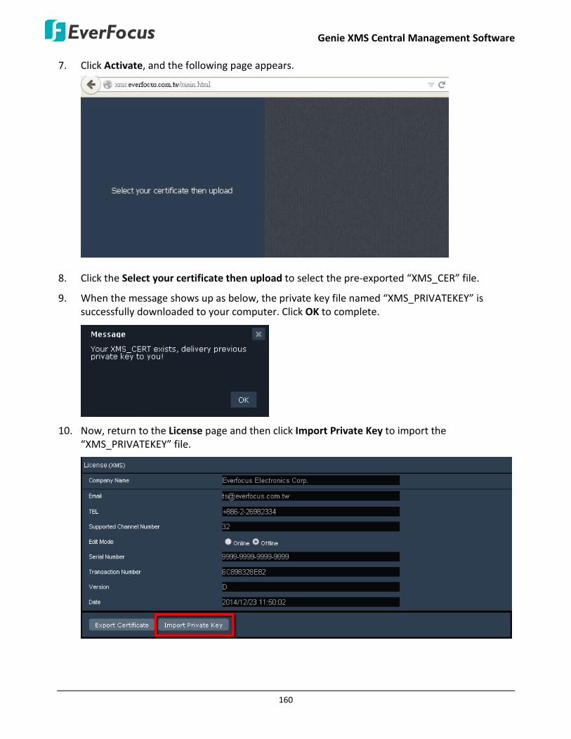
Genie XMS Central Management Software
160
7. Click Activate, and the following page appears.
8. Click the Select your certificate then upload to select the pre-exported “XMS_CER” file.
9. When the message shows up as below, the private key file named “XMS_PRIVATEKEY” is successfully downloaded to your computer. Click OK to complete.
10. Now, return to the License page and then click Import Private Key to import the “XMS_PRIVATEKEY” file.
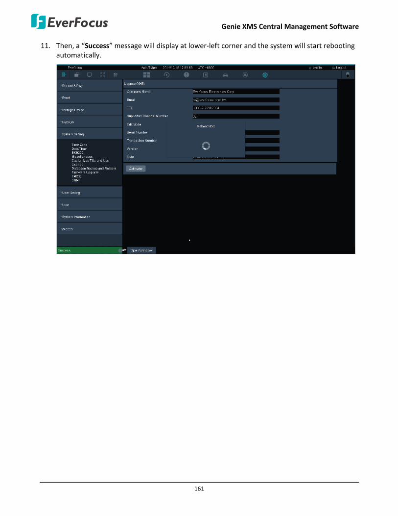
Genie XMS Central Management Software
161
11. Then, a “Success” message will display at lower-left corner and the system will start rebooting automatically.

Genie XMS Central Management Software
162
4.7.7 Database Backup and Restore
On the left-side menu bar, click System Setting and then click Database Backup and Restore. You can back up the system’s configurations, and the settings can be restored to the current computer or imported to another computer.
Database Export: Click Apply to export the system’s configuration file.
Database Import: Click Select to select a system’s configuration file and then click Upload to apply the settings.
To set up the Auto Backup function:
You can also use the Auto Backup function for the system to automatically back up the configurations according to a specified schedule to a FTP server a.
Please follow the steps below:
1. Check the Auto Backup function.
2. Enter the FTP Server address, port, user account, password and the archive path.
3. Specify a timeout period (second). It will disconnect the session when this timeout is reached.
4. Select a date and time for the system to automatically back up the system’s configurations. You can set up multiple backup schedules.
5. Click Apply to save the setting.
6. You can search the auto backup file in the Auto Backup Log list.

Genie XMS Central Management Software
163
4.7.8 Firmware Upgrade
On the left-side menu bar, click System Setting and then click Firmware Upgrade. You can upgrade the system’s firmware here. Click Select to select a firmware file and then click Upgrade to start upgrading.

Genie XMS Central Management Software
164
4.7.9 EMX32
On the left-side menu bar, click System Setting and then click EMX32. To display the Matrix Live View of the system on the monitor of EMX32, you need to enter the IP address, port, user name and password of that EMX32 on this setting page. Then, click Apply to save the settings.
After the above configuration, on the Live View window, click EMX32 to display the Matrix Live View on the monitor of EMX32. Note this function is only functional for 2x2, 3x3 and 4x4 layout.

Genie XMS Central Management Software
165
4.7.10 SNMP
On the left-side menu bar, click System Setting and then click SNMP. You can use the SNMP to monitor, manage, configure, and collect information from the connected systems on which you set up the SNMP.
SNMP On: Check to enable the SNMP service.
SNMPv1, SNMPv2c Service: Check to enable SNMPv1 or SNMPv2c service.
Community: Enter a name to identify the SNMP community.
SNMPv3 Service: Check to enable SNMPv3 service.
Account: Enter the user account name.
Password: Enter a password for the user account.
Information
SNMP System Name: Enter a name for this SNMP system.
SNMP System Location: Enter a location of the SNMP system.
SNMP System Contact: Enter contact information such as email or phone number of the SNMP system maintainer.
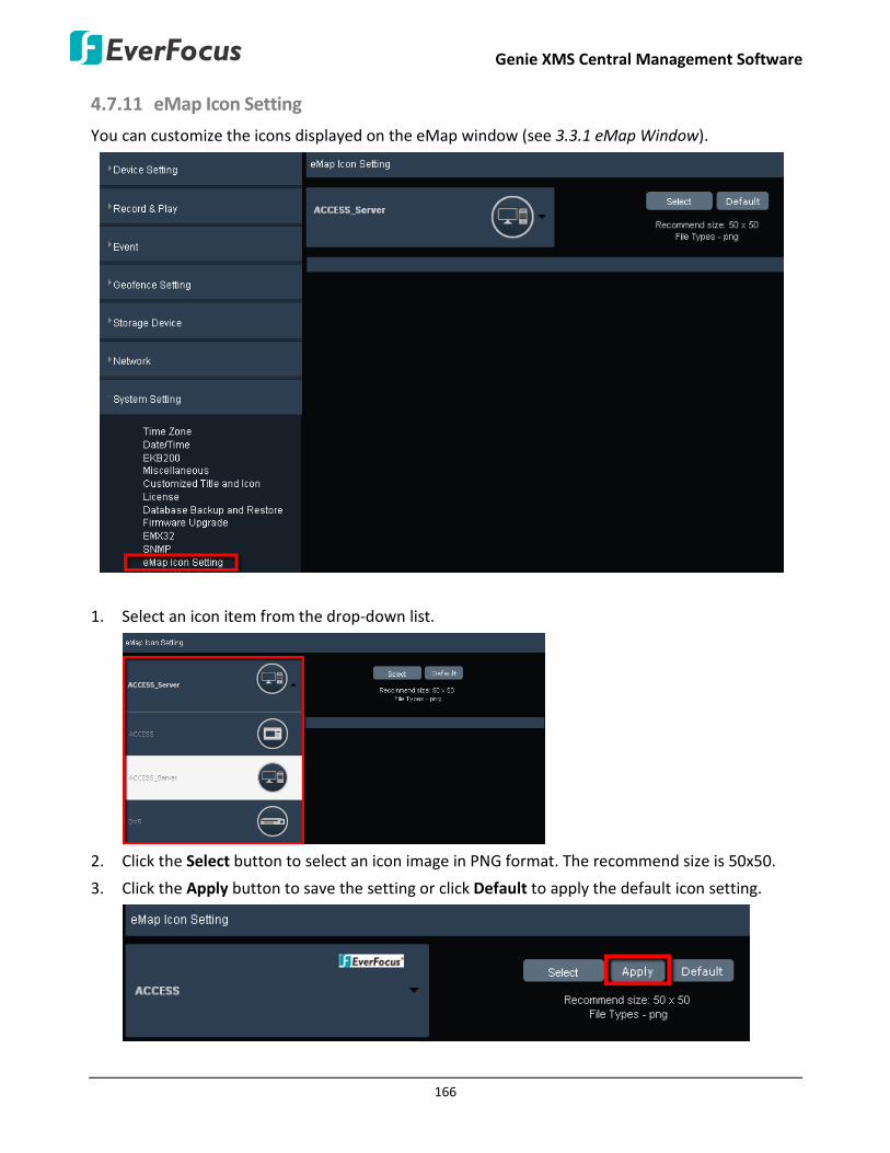
Genie XMS Central Management Software
166
4.7.11 eMap Icon Setting
You can customize the icons displayed on the eMap window (see 3.3.1 eMap Window).
1. Select an icon item from the drop-down list.
2. Click the Select button to select an icon image in PNG format. The recommend size is 50x50.
3. Click the Apply button to save the setting or click Default to apply the default icon setting.

Genie XMS Central Management Software
167
4.7.12 Black/White List
Use this page to specify IP addresses that are allowed / denied to access this XMS server. By default, any IP address can access the XMS server.
Note: The Allowed IP addresses only become relevant when the Denied items contain a Network or Range, and the supervisor wants to allow one or more IP addresses within that excluded range or network. In such a scenario, the user would enter the excluded range or network for the Denied items, and enter the exceptions for the Allowed items.
Current Black/White List Setting is: Check the box to enable the function.
Filter Type: Select Access or Deny for the following IP settings.
Rule: Select a network rule and then fill in the IP information in the below boxes.
• Single: Type a single IP address in the IP Address field below. • Network: Type the IP address and subnet mask in the field below. • Range: Type a range for the IP addresses.
Click Apply to save the settings.
Click Cancel to cancel the settings.
Select an item below and click Delete to delete the item.

Genie XMS Central Management Software
168
4.8 Failover Setting You can set up the Failover setting for another XMS server to take over as a backup server once the XMS server you are currently operating failed. On the left-side menu bar, click Failover Setting > Server Setting and then configure the settings.

Genie XMS Central Management Software
169
4.9 User Setting On the left-side menu bar, click User Setting. In this menu, different users with administrator privileges are allowed to set up the settings according to their preferences. The system will recognize the user and remember their preferences.
4.9.1 User Time Zone
On the left-side menu bar, click the User Setting, and then click User Time Zone. Users with administrative privileges can set up their own time zone and country when accessing the system from a remote site.
1. Select a time zone, or click on the map to select the time zone.
2. Select the country, or click on the map to select the country.
3. You can also click Auto Detection for the system to automatically detect the time zone and country. Then, click Share Location when the location permission request pops up.
4. Click Apply to save the setting.

Genie XMS Central Management Software
170
4.9.2 Local Save Settings
On the left-side menu bar, click the User Setting, and then click Local Save Settings.
Save Recording in: Click Select to select a path for saving the live view recording files. Please refer to 3.3.2 Live View Tool Bar. You can click Open File Path to find the files.
Save Snapshot in: Click Select to select a path for saving the snapshot images. Please refer to 3.3.2 Live View Tool Bar. You can click Open File Path to find the files.
Save Archive in: Click Select to select a path for saving the archive files. Please refer to 4.2.5 Archive.
You can click Open File Path to find the files.
Click Apply to save the settings.

Genie XMS Central Management Software
171
4.9.3 OSD Setting
On the left-side menu bar, click the User Setting, and then click OSD Settings.
Camera Name: Check to display camera’s name on the live view window.
Bit Rate: Check to display camera’s bit rate on the live view window.
Date/Time: Check to display date and time on the camera’s live view window.
Font Size (12~300): Enter the font size for the above settings.
Click Apply to save the settings.

Genie XMS Central Management Software
172
4.9.4 Change Own Password
On the left-side menu bar, click the User Setting, and then click Change Own Password. Users with administrative privileges can change their own password on this page. Enter a password and then enter it again in the Confirm filed to confirm the password. Click Apply to save the setting.

Genie XMS Central Management Software
173
4.9.5 Language
On the left-side menu bar, click the User Setting, and then select the preferred language on the left-side Language drop-down list.
4.9.6 Page
You can set up the default page layout when log in to the system.
1. Select a page from the Page drop-down list. The system will automatically save the setting.
2. The system will display the selected layout page every time when users re-open a Web browser to log in the system.

Genie XMS Central Management Software
174
4.10 User Management On the left-side menu bar, click User Management. You can create new users and manage the user privileges and user groups in this menu.
4.10.1 User Account
On the left-side menu bar, click User Management and then click User Account. You can create multiple user accounts and assign the users to a specific group using this page.

Genie XMS Central Management Software
175
The User Account lists the current users of the system. To edit the user list or to add users, click Edit Mode, and the buttons marked in the red frame will display. After the settings, click Update to save the settings. Please see the detailed instructions below.
Add User:
Click the Add button, the window displays as below. Input the user name and password for the user, and then select a user group from the drop-down list (you have to create a group first, see 4.10.2 User Group). Optionally input the email address of the user. Click the Save button, the user should be added to the User Management list.
Note: There are three group types for the user account: Administrator, Operator and Viewer. Each group type is applied with the fixed privileges as listed below. You can also create a new group type with self-specified privileges, please see 4.10.2 User Group.

Genie XMS Central Management Software
176
Delete User:
Check to select the user which you want to delete. Click Delete to delete the user.
Update User Setting:
To change user group of the user, directly click on the User Group column of the user to switch between user groups. To change the user name, directly click on the User Name column and enter a new name. Click the Update button to save the settings.
Reset Password:
Check to select a user and click Rest Password. The window will show as below, and then enter a new password for the user.

Genie XMS Central Management Software
177
4.10.2 User Group
On the left-side menu bar, click User Management and then click User Group. Administrators can create new user groups with self-specified privileges. Please follow the steps below:
1. Click Edit Mode, and then click Add.
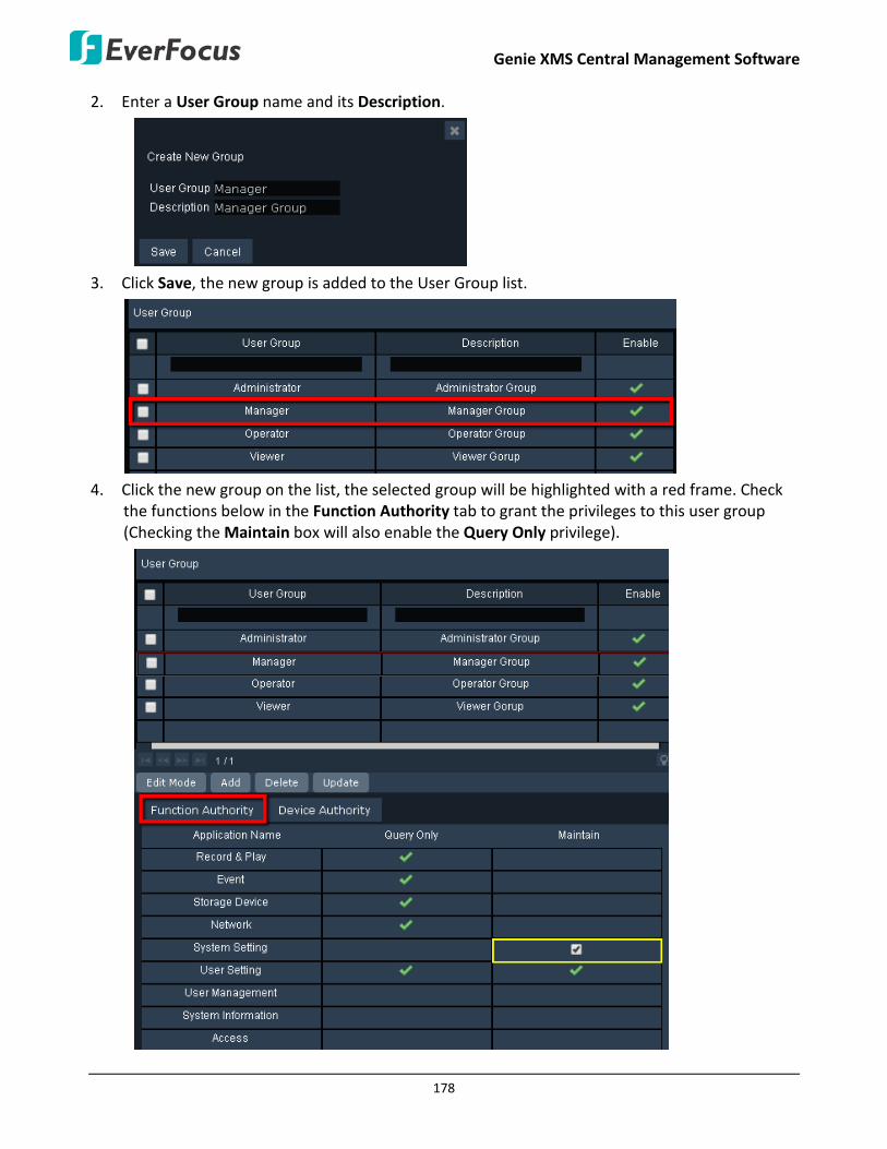
Genie XMS Central Management Software
178
2. Enter a User Group name and its Description.
3. Click Save, the new group is added to the User Group list.
4. Click the new group on the list, the selected group will be highlighted with a red frame. Check
the functions below in the Function Authority tab to grant the privileges to this user group (Checking the Maintain box will also enable the Query Only privilege).

Genie XMS Central Management Software
179
5. Click Device Authority button to display the device list. You can check the View and Playback boxes of the devices to allow this user group to be able to view the device’s live image and play back its recordings.
6. Click Update to save the settings.
7. You can still modify the group name and description, disable it or change privileges by clicking on each of the setting field and check box. Then, click Update to save it.
8. You can also delete the user group. Check to select the group you want to delete, and then
click Delete.

Genie XMS Central Management Software
180
4.11 System Information On the left-side menu bar, click System Information. You can view or export system information in this menu.
4.11.1 System
On the left-side menu bar, click System Information and then click System. You can change the server’s name and check its version here.
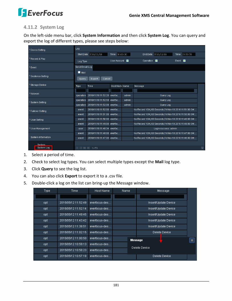
Genie XMS Central Management Software
181
4.11.2 System Log
On the left-side menu bar, click System Information and then click System Log. You can query and export the log of different types, please see steps below:
1. Select a period of time.
2. Check to select log types. You can select multiple types except the Mail log type.
3. Click Query to see the log list.
4. You can also click Export to export it to a .csv file.
5. Double-click a log on the list can bring-up the Message window.

Genie XMS Central Management Software
182
4.11.3 Server Status
On the left-side menu bar, click System Information and then click Server Status. You can check the system’s CPU, Memory and Network statuses in this menu. The Overview displays the above three system statuses together; however, you can also click each tab to see the detailed status respectively.

Genie XMS Central Management Software
183
4.11.4 Recording Data Report
On the left-side menu bar, click System Information and then click Recording Data Report. This Recording Data Report shows the recording status of all the devices. Please follow the steps below:
Note:
1. To activate the Recording Data Report function, the Record to Server (IP Camera / RTSP device) and Backup to Server (DVR / NVR) must be enabled on the device maintain page. Also, a Storage Device group must be assigned to the device.
2. If both of the “IP camera / RTSP device schedule recording” and “DVR / NVR auto backup”
functions have been enabled on your Genie XMS server, please assign different Storage Device group to IP camera / RTSP device and DVR / NVR. For example, assign Storage Device A to IP camera and Storage Device B to DVR.

Genie XMS Central Management Software
184
To query a Recording Data Report:
1. Click to select a Date and Time.
2. Click Related Device List to select devices.
3. Click Query to display the recording status report.
4. You can click the bar under the Day or Hour to show the report in different timeline formats.
5. Click Today to show today’s data; click < or > to see the previous or the next day.
The recording status indication:
: A yellow block represents only events are recorded during this time block.
: A blue block indicates the continuous recording during this time block.

Genie XMS Central Management Software
185
5. Licensed Functions
Functions described in this chapter are license required.
EverFocus Genie XMS is an open system integration platform which is well designed with a scalable and modular architecture that can be easily expanded or integrated with various systems or applications such as POS, LPR, access control and fleet management. Most importantly, Genie XMS can analyze the big data and information accumulated from all these systems in order to make prediction, to provide timely response and even to optimize business performance, creating long-term value for clients across various verticals and industries.
If you need any customized service, please contact EverFocus for more details.
Xfleet Management
Access Control Management
Device Name :
Longitude :
EMV1200HD
121.6503
25.0861
GPS Speed :
X: +1 Y: -1 Z: +12
70KPH
Event Type :
Latitude :
G Sensor :
Chapter
5

Genie XMS Central Management Software
186
5.1 Xfleet Management This function is license required.
Xfleet is a Web-based fleet management system which integrates GPS positioning, 3G/4G mobile wireless communication, GIS (Geographic Information System) techniques and Geofence, allowing users to easily track, monitor and manage any type of fleet vehicles on a Web browser anywhere and anytime.
With Xfleet, not only can you reduce overall costs by effectively utilizing resources such as vehicles, fuel, and manpower, but you can also improve the management efficiency and business performance by keeping and analyzing the historical records (graphical reports) of the vehicle data as needed.
For more details about Xfleet, please refer to the User’s Manual of Xfleet Management Software.
Device Name :
Longitude :
EMV1200HD
121.6503
25.0861
GPS Speed :
X: +1 Y: -1 Z: +12
70KPH
Event Type :
Latitude :
G Sensor :
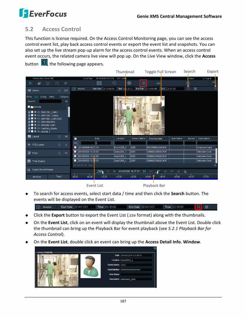
Genie XMS Central Management Software
187
5.2 Access Control This function is license required. On the Access Control Monitoring page, you can see the access control event list, play back access control events or export the event list and snapshots. You can also set up the live stream pop-up alarm for the access control events. When an access control event occurs, the related camera live view will pop up. On the Live View window, click the Access
button , the following page appears.
Event List Playback Bar
ExportToggle Full Screan SearchThumbnail
To search for access events, select start data / time and then click the Search button. The
events will be displayed on the Event List.
Click the Export button to export the Event List (.csv format) along with the thumbnails.
On the Event List, click on an event will display the thumbnail above the Event List. Double click the thumbnail can bring up the Playback Bar for event playback (see 5.2.1 Playback Bar for Access Control).
On the Event List, double click an event can bring up the Access Detail Info. Window.

Genie XMS Central Management Software
188
5.2.1 Playback Bar for Access Control
Hour / Day
Step Backward
Backward
Time
Forward / Pause
Step Forward
Speed
Time Bar Playback Point
Select Time Period
A-B Playback
ArchiveServer/Device
Hour / Day: Click to switch the Time Bar to Hour mode or Day mode.
Step Backward: When you pause the playback, click this button to step backward one second of the playback time.
Backward: Click to start or pause backward playback.
Time: Indicates the current playback time of the recording.
Forward / Pause: Click to start or pause forward playback.
Step Forward: When you pause the playback, click this button to step forward one second of the playback time.
Speed: Drag the Speed bar to select a playback speed.
Select Time Period: Click the button and a “Red Time Area” appears on the playback bar. Drag the right/left edge to set up the time period for A-B playback (see steps later).
A-B Playback: After setting up the time period, click A-B Playback and then click the Play button to start playing back the recordings of the selected time period. The recordings will be played back from the playback point at the first time and then the A-B repeat playback goes on (see steps on the next page).
Archive: After setting up the time period, click Archive to archive the recordings of the selected time period (see steps on the next page).
Server/Device: This function is only available for DVR/NVR/Mobile DVR. You can choose to play back the recordings from the Device or Genie XMS Server. Click to switch between Server and Device. Note that to enable this function, you have to enable the Play Back from Server functions on the Device Maintain Page.

Genie XMS Central Management Software
189
Time Bar: Drag the Time Bar to the left or right to select a desired time. The color on the Time Bar indicates the recording types (Yellow: Event Recording; Blue: Continuous Recording).
Playback Point: Indicates the time point of the current playback recording.

Genie XMS Central Management Software
190
5.2.2 Adding Access Control Server to the XMS Server
To add Access Control server to the XMS server, you have to add Access Control server and then select the desired Access Controllers. If you want the XMS server to pop-up live view window from the IP camera when a cardholder swipes a card, then you should further add the IP cameras to the Access Controller.
To add an Access Control server (ENS2000) to the XMS server:
1. On the Live View Window, click Setting to bring up the left-side setting menu. Click Device in the Device Setting field, the Device List Setup page appears on the right window.
2. Click Add to enter the Device Maintain page. Select AccessServer from the Device Type drop-down list and then configure the related settings.
Enable: Check the box to enable the device.
Device Name: Enter a name for the device.
IP: Enter the IP of the Device.
HTTP Port: By default, the port is set to 80. Change the port number if necessary.
User Account: Enter the user ID of the device.
Password: Enter the password of the device.
Port Forwarding: Check the box and then click the Save button to enable the Port Forwarding function. The port number assigned by the XMS server will be displayed in the

Genie XMS Central Management Software
191
Forward Port Number field. This function is useful if you want to remotely access XMS server and view the streams or remotely access the device live view from outside of the LAN via the internet (WAN). For this function to work, you have to configure the network setting in advance (see 4.4.1 Network Setting). To remotely access the device live view through WAN, simply type the IP address appended with forwarded port number (for example http://118.122.53.106:20003) in the address field of a browser.
Forward Port Number: After enabling the Port Forwarding function and then click the Save
button , the port number assigned by the XMS server will be displayed in this field.
Used: Select Used / Unused to enable / disable the access control event function.
Related Device List: For certain functions, it’s required to establish the connection among devices, and the related devices will be listed here (see 5.2.3 Setting up Event Configurations).
3. Select Access Server from the Device Type drop-down list and configure the related settings.
4. Click Related Devices List , the Access Controllers connected to this Access Control server will be listed on the bottom of this page.
5. Check the boxes to select the desired Access Controllers to add to this Access Control server.
6. Click the Save button to save the settings. The device will be added to the Device List. You
can also click the Open Setting Page button to access the Web interface of the device.
To add IP cameras to the Access Controller in order to activate the live view window pop-up function:
1. On the Main Page, click Device Info to enter the Device List, then double-click on the Access Controller you added to the Access Control server.
Double-click on the added Access Controller

Genie XMS Central Management Software
192
2. On the Maintain Page, select the related IP cameras you want to add to this Access Controller.
Enable: Check the box to enable the device.
Device Name: Enter a name for the device.
IP: Enter the IP of the Device.
HTTP Port: By default, the port is set to 80. Change the port number if necessary.
User Account: Enter the user ID of the device.
Password: Enter the password of the device.
Host Name: Select a host from the drop-down list.
Port Forwarding: Check the box and then click the Save button to enable the Port Forwarding function. The port number assigned by the XMS server will be displayed in the Forward Port Number field. This function is useful if you want to remotely access XMS server and view the streams or remotely access the device live view from outside of the LAN via the internet (WAN). For this function to work, you have to configure the network setting in advance (see 4.4.1 Network Setting). To remotely access the device live view through WAN, simply type the IP address appended with forwarded port number (for example http://118.122.53.106:20003) in the address field of a browser.
Forward Port Number: After enabling the Port Forwarding function and then click the Save
button , the port number assigned by the XMS server will be displayed in this field.
eMap Layer: Select an eMap layer to apply this device to. This eMap layer will be applied with the Go to eMap Layer function when event occurs (see 3.3.1.1 Go to eMap Layer).

Genie XMS Central Management Software
193
Related Device List: For certain functions, it’s required to establish the connection among devices, and the related devices will be listed here (see 5.2.3 Setting up Event Configurations).
3. Click the Save button to save the settings. The IP cameras will be added to the Access Controller.

Genie XMS Central Management Software
194
5.2.3 Setting up Event Configurations
After adding the Access Control server to the XMS server, and added the IP cameras to the Access Controller (see 5.2.2 Adding Access Control Server to the XMS Server), you can set up the live stream pop-up alarm for the access control events. When an enabled event type is triggered, an alarm window will pop up to display the related camera’s live view stream.
To enable / disable Live View window pop-up function, check / uncheck Disable Popup Windows on Live View on the Event Setting page (Setting > Event > Event Setting).

Genie XMS Central Management Software
195
You can also set up various event actions for each event type. When an event occurs, the configure event actions will be activated for notification:
Note: The pop-up notification windows will be displayed on the XMS window no matter on Live View, Playback or any page you are currently using. If you want to disable Live Stream Alarm Pop-up window on Live View or Playback View, check Disable Popup Windows on Live View or Disable Popup Windows on Playback View and click the Apply button (see 4.2.3 Event Setting).
1. On the Main Page, click Setting > Event > Alarm/Event Setting (Device). Select Access Controller from the Device drop-down list.
2. Select an event type from the drop-down list.
3. Checked the Enable column to enable the event notification function. Check the desired event
notifications for the selected event.
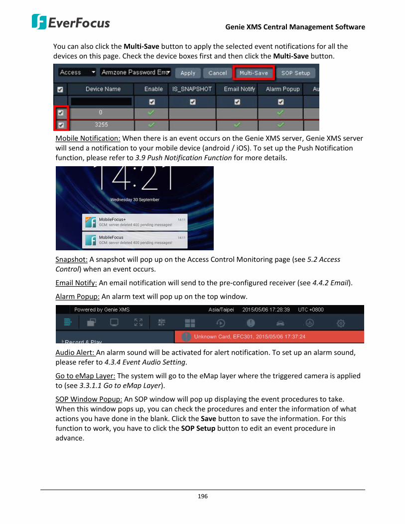
Genie XMS Central Management Software
196
You can also click the Multi-Save button to apply the selected event notifications for all the devices on this page. Check the device boxes first and then click the Multi-Save button.
Mobile Notification: When there is an event occurs on the Genie XMS server, Genie XMS server will send a notification to your mobile device (android / iOS). To set up the Push Notification function, please refer to 3.9 Push Notification Function for more details.
Snapshot: A snapshot will pop up on the Access Control Monitoring page (see 5.2 Access Control) when an event occurs.
Email Notify: An email notification will send to the pre-configured receiver (see 4.4.2 Email).
Alarm Popup: An alarm text will pop up on the top window.
Audio Alert: An alarm sound will be activated for alert notification. To set up an alarm sound, please refer to 4.3.4 Event Audio Setting.
Go to eMap Layer: The system will go to the eMap layer where the triggered camera is applied to (see 3.3.1.1 Go to eMap Layer).
SOP Window Popup: An SOP window will pop up displaying the event procedures to take. When this window pops up, you can check the procedures and enter the information of what actions you have done in the blank. Click the Save button to save the information. For this function to work, you have to click the SOP Setup button to edit an event procedure in advance.

Genie XMS Central Management Software
197
4. Click the Apply button to save the settings.

EverFocus Electronics Corp. EverFocus Taiwan: 12F-1, No.79, Sec. 1, Shin-Tai Wu Road, Hsi-Chih, New Taipei City, Taiwan TEL: +886 2 2698 2334 FAX: +886 2 2698 3943 www.everfocus.com.tw [email protected]
EverFocus Europe - Germany: Albert-Einstein-Strasse 1, D-46446 Emmerich, Germany TEL: +49 2822 93940 FAX: +49 2822 939495 www.everfocus.de [email protected]
EverFocus China - Beijing: Room 609, Technology Trade Building, Shangdi Information Industry Base, Haidian District, Beijing 100085, China TEL: +86 10 6297 3336~39 FAX: +86 10 6297 1423 www.everfocus.com.cn [email protected]
EverFocus China - Shenzhen: 4F, No. 2, D4 Building, Wan Yelong Industrial Park, Tangtou Road, Shiyan, Baoan, Shenzhen, Guangdong 518101, China TEL: +86 755 2765 1313 FAX: +86 755 2765 0337 www.everfocus.com.cn [email protected]
EverFocus USA - California: 1801 Highland Avenue, Unit A, Duarte, CA 91010, USA TEL: +1 626 844 8888 FAX: +1 626 844 8838 www.everfocus.com [email protected]
EverFocus Japan: 3F, Kuramochi, Building II 2-2-3 Koto-Bashi, Sumida-Ku, Tokyo, 130-0022, Japan TEL: +81-3-5625-8188 FAX: +81 3 5625 8189 www.everfocus.co.jp [email protected]
Your EverFocus product is designed and manufactured with high quality materials and components which can be recycled and reused. This symbol means that electrical and electronic equipment, at their end-of-life, should be disposed of separately from your household waste. Please, dispose of this equipment at your local community waste collection/recycling centre. In the European Union there are separate collection systems for used electrical and electronic product. Please, help us to conserve the environment we live in!
Ihr EverFocus Produkt wurde entwickelt und hergestellt mit qualitativ hochwertigen Materialien und Komponenten, die recycelt und wieder verwendet werden können. Dieses Symbol bedeutet, dass elektrische und elektronische Geräte am Ende ihrer Nutzungsdauer vom Hausmüll getrennt entsorgt werden sollen. Bitte entsorgen Sie dieses Gerät bei Ihrer örtlichen kommunalen Sammelstelle oder im Recycling Centre. Helfen Sie uns bitte, die Umwelt zu erhalten, in der wir leben!
P/N: 4605PNRP18B033A_V.B