Generation Protection final
44
Generation Protection 2016 Operator Training Seminar Billy Lee System Operations Administrator Spring 2016
Transcript of Generation Protection final

Generation Protection2016 Operator Training Seminar
Billy LeeSystem Operations Administrator
Spring 2016

Objectives
• In terms of excitation, identify two abnormal operating conditions for generators, unlike other power system components.
• Identify the difference between a generator sequential and simultaneous trip.
• Identify the relay protection scheme that senses power flowing into a generator from the power system.
• Identify the type of protection relay used in detecting a phase-phase stator winding fault.
• Given a one – line drawing identify the reverse power relay, frequency relay and differential relay used in generator protection. (Schematic to accompany test question in LMS).
2
PUBLIC
NERC STANDARD PRC-001-1.1 (ii)
• R1. Each Transmission Operator, Balancing Authority and Generator Operator shall be familiar with the purpose and limitations of Protection System schemes applied in its area.
3
PUBLIC 4
August 14, 2003Northeast Blackout

PUBLIC 5
Pre-existing conditions
• Critical voltage day• Wide area transfers • Planned Transmission and Generation
outages
PUBLIC 6
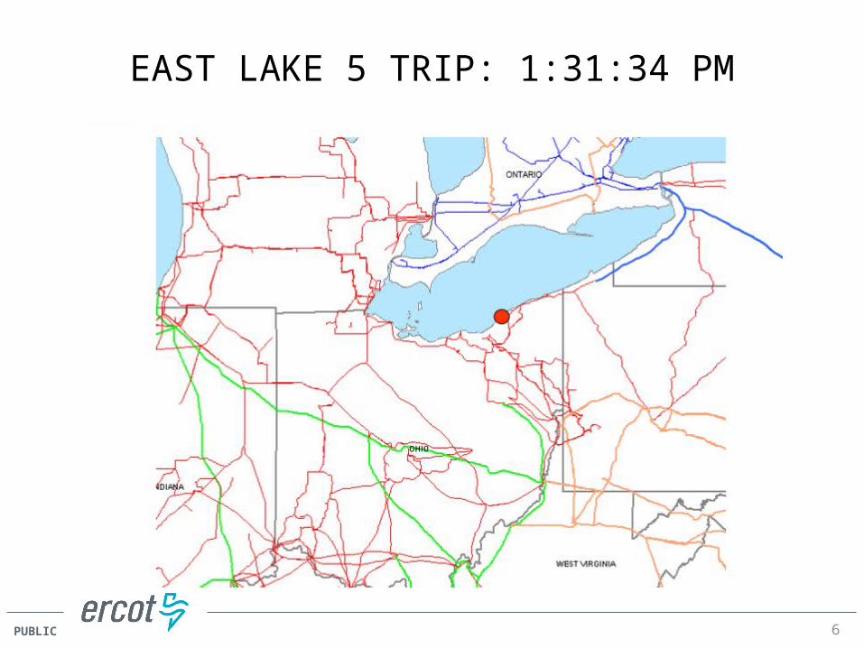
EAST LAKE 5 TRIP: 1:31:34 PM

PUBLIC
East Lake 5 Exciter Failure Causes Trip
7

PUBLIC 8
How does this relate to Emergency operations?

9
9
Objective 1
PUBLIC 10
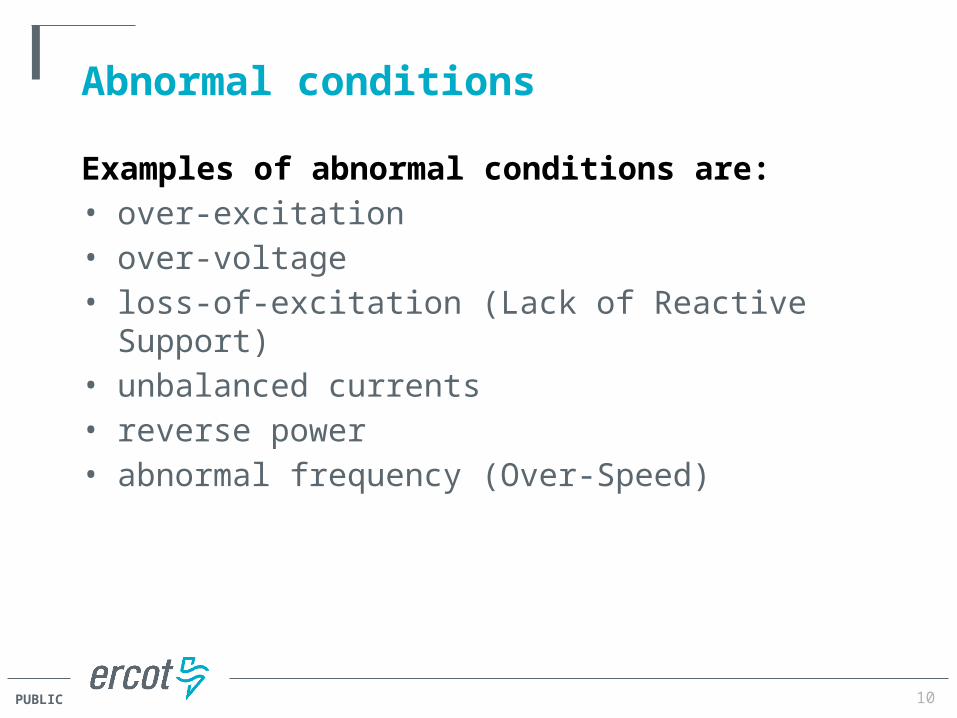
Abnormal conditions
Examples of abnormal conditions are: • over-excitation• over-voltage• loss-of-excitation (Lack of Reactive Support)• unbalanced currents• reverse power• abnormal frequency (Over-Speed)

PUBLIC 11
Bulk Electric System Emergency
• Any abnormal system condition that requires
automatic or immediate manual action to prevent or
limit the failure of transmission facilities or generation
supply that could adversely affect the reliability of the
Bulk Electric System.

PUBLIC 12
Reliably operate the system you have!
Power System Overview

PUBLIC 13
Relay Device Numbers
Listed below are relay device numbers typically found on a generator one-line diagram:• 21- Distance (Device) Relay- backup for
system and generator zone phase faults.• 24- Volts/Hertz protection• 32- Directional (Reverse Power) relay or anti-
motoring protection• 40- Loss of Excitation(Field relay)• 46- Negative Phase Sequence Current• 49- Stator Thermal Protection• 50- Instantaneous Overcurrent• 51G- Time over-current ground relay• 51TN- Backup for ground faults• 51V- Voltage controlled or voltage –
restrained time over current relay
• 59- Over- voltage protection• 59GN- Stator ground fault protection• 60- Voltage Balance relay• 62B- Breaker Failure timer• 64F- Field Ground Detector • 78- Loss of Synchronism• 81- Frequency Relay (under and over
frequency)• 86- Hand reset lockout auxiliary relay• 87G- Differential Relay – primary phase
fault protection• 87N- Stator ground fault differential
protection• 87U- Differential relay for overall generator
and transformer protection

14
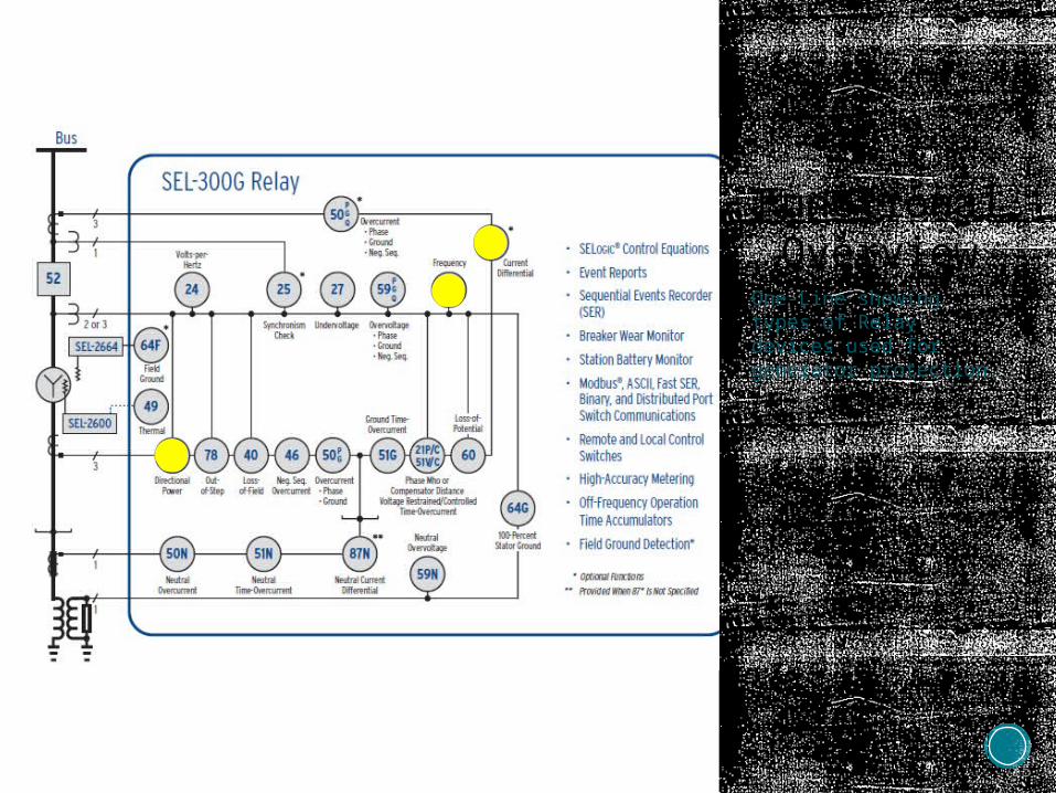
SEL-700GSEL-300G
Numerous current, voltage, frequency, distance, power, and out-of-step elements provide comprehensive protection for large, medium, and small generators.
Protection includes: Stator Ground fault, current differential, out-of-step, over-excitation, directional power, and event reporting.
https://www.selinc.com/SEL-300G/
15
Functional Overview
One-Line showing types of Relay devices used for generator protection.

16
16
Objective 2

PUBLIC 17
Protective actions for generator shutdowns
• Generator Trip• Simultaneous Trip• Sequential Trip• Manual Turbine Trip• Manual Runback and Trip• Automatic Runback• Manual Runback
PUBLIC 18
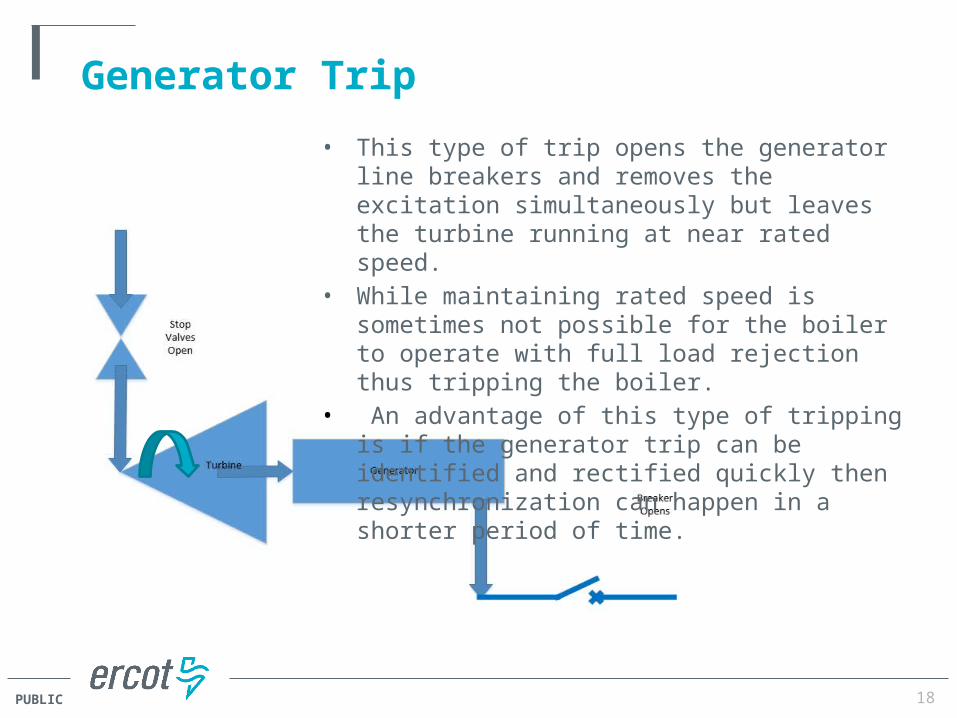
Generator Trip• This type of trip opens the generator line breakers
and removes the excitation simultaneously but leaves the turbine running at near rated speed.
• While maintaining rated speed is sometimes not possible for the boiler to operate with full load rejection thus tripping the boiler.
• An advantage of this type of tripping is if the generator trip can be identified and rectified quickly then resynchronization can happen in a shorter period of time.

PUBLIC 19
Simultaneous Trip
A simultaneous trip is acceptable for all generator faults, and generally provides the highest degree of protection for the generator although it does permit a small over-speed and a slight possibility of high over-speed.
This type of trip the turbine valves close, opens the generator line breakers and removes the excitation simultaneously.

PUBLIC 20
Sequential Trip• Sequential tripping, trips the turbine valves
closed, then the reverse power relay operates in about 3 seconds and the generator line breakers are opened.
• When the generator breakers open the excitation is tripped (field breaker trip).
• This is the preferred tripping for most faults in the turbine or steam generator (boiler).
• Some schemes have a backup reverse power timing circuit for tripping on reverse power.
PUBLIC 21
What is the difference between a generator Simultaneous Trip and a Sequential Trip?
• Simultaneous trip trips turbine valves closed, opens the generator breakers and removes excitation simultaneously where sequential trips turbine first then reverse power relay trips generator breakers and excitation.

PUBLIC 22
Manual Turbine Trip
• The Operator may manually trip the turbine, this should cause
Reverse Power relaying to trip the generator breakers and the
excitation.
• Note: There are no cases for which manually tripping the generator
breakers is recommended!
• This is because the generator breakers should not normally be
tripped until the turbine has tripped and reverse power automatically
trips the generator breakers with reverse power relaying.

PUBLIC 23
Additional Protective actions
• Manual Runback and Trip• Manual Runback• Automatic Runback

PUBLIC 24
Reverse Current Protection
• Motoring of a generator will occur when the mass steam flow of the prime mover (turbine) is reduced such that it develops less than no load losses while the generator is still on line.
• It is important to note that motoring at synchronous speed will not harm the generator but may damage the turbine though over heating.
• Although motoring the generator at less than synchronous speed will cause immediate damage due to induced rotor currents resulting in excessive heating.
• Also stator inrush currents may break the stator armature end—winding ties.

25
Broken turbine blade
Here you see broken turbine blades – the root cause of the fire.

26
Motoring Damage causing a
hydrogen fire
Hydrogen Leak –
Broken seals that allowed hydrogen to get to atmosphere. The shell to the right is the generator shell. The motor is the turning gear.

27
Motoring Damage causing a
hydrogen fire
Here you see Ground Floor Cable Trays –Next to the 4160 switch gear and hydrogen seal oil system. Fortunately the seal oil system didn’t explode.

28
Motoring Damage causing a
hydrogen fire
Here you see Mezzanine to Cable Spreader Room – On the mezzanine near the vital AC and emergency DC.

29
Motoring Damage causing a
hydrogen fire
Here you see Emergency DC – On the mezzanine deck. The breaker handles melted.

30
Motoring Damage
Motoring without excitation.
Here you see rotor tooth damage as a result of localized heating and arcing.
Rotor Tooth Tip Damage Due to Motoring
Photograph compliments of National Electric Coil, Columbus OH

31
31
Objectives 3, 4 & 5
PUBLIC 32
Reverse Power Relay
• A Reverse Power (32 Directional) relay is used for generator protection. It senses power flowing into the generator rather than power flowing out to the system.
• A typical arrangement of a reverse power protection circuit employs both a Current Transformer (CT) and Voltage Transformer (VT) to power the relay and protect the generator.
• Reverse Power relay should be connected to produce a simultaneous trip.
• A Breaker Failure protection should be initiated because generator breaker failure may be what caused the reverse power flow condition.
33
Reverse Power Relay
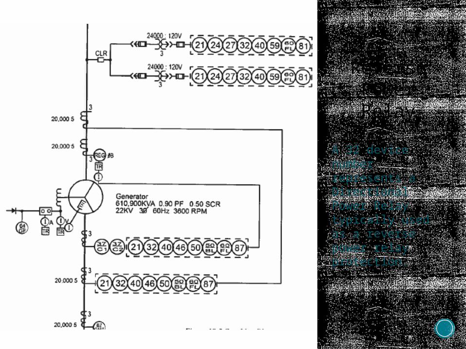
A 32 device number represents a Directional Power Relay typically used as a reverse power relay protection.

34
Reverse Power Relay
A 32 device number represents a Directional Power Relay typically used as a reverse power relay protection.
Figure 3-18 Reverse Power Relays
Source of Motoring
PowerG
32-1
32-1
86NE
86E
Turbine Trip BKRTrip Field Trip
86NE
86NE 86E 86E
86E
86NENON-ELEC TRIPS
OTHER ELEC TRIPS
64 49 32-2
32-1
PUBLIC 35
Generator Phase Faults
• A stator phase – to – phase fault is any electrical fault between two phases of the armature winding.
• This type of fault is very serious because it produces large amounts of current damaging to the winding if allowed to persist.
• Also if allowed to grow it will include a ground fault thus causing significant damage to the stator core.
• Damage of this kind will result in costly and long repair times. • Phase – to- phase fault in the winding is detected by a (87G)
differential relay.

36
Phase to Phase Fault
Detection
A Differential relay (87) operates by comparing the current going into a phase with the current going out.
Protected Equipment
Operating Winding
Figure 4-01 Phase-to-Phase Fault Detection
Restraining Windings
Relay

PUBLIC 37
Backup Protection
• The need for backup protection is to protect the generator by detecting system faults that have not been isolated as they should have been.
• System backup protection as applied to the generator consist of time delay protection for line-to-ground and multiphase fault conditions.
• Backup generator protection schemes are used to protect against failure of the primary system protective relaying and subsequent long clearing faults.
• Backup protection is usually provided by two types of relays, over-current and distance relays.

38
Backup Overall Differential Protection
The generator auxiliary transformer may be included in the differential zone.
Figure 4-10 Generator Phase Fault Backup
Overall Differential Scheme
Alternate Connection
Auxiliary Transformer
87T
87T

PUBLIC 39
Over/Under Frequency Protection
• Over frequency can be caused by loss of load on a generator.
• Under frequency can be caused by significant addition of load to a generator or sudden reduction of mechanical input power to the generator.
• Typically a (81) Frequency relay is used to detect these conditions.

PUBLIC 40
Under Frequency Protection

PUBLIC 41
Over Frequency Protection
Frequency Range Delay to Trip
Below 60.6 Hz down to and including 60 Hz
No automatic tripping (Continuous operation)
Below 61.6 Hz down to and including 60.6 Hz Not less than 9 minutes
Below 61.8 Hz down to and including 61.6 Hz Not less than 30 seconds
61.8 Hz or above No time delay required

PUBLIC 42
Review Objectives
• In terms of excitation, identify two abnormal operating conditions for generators, unlike other power system components.
• Identify the difference between a generator sequential and simultaneous trip.
• Identify the relay protection scheme that senses power flowing into a generator from the power system.
• Identify the type of protection relay used in detecting a phase-phase stator winding fault.
• Given a one – line drawing identify the reverse power relay, frequency relay and differential relay used in generator protection. (Schematic to accompany test question in LMS).

PUBLIC 43
References
• HPC Technical Services Generator Protection G404
• HPC Technical Services Utility Generators: Theory, Controls,
Operation, Maintenance & Testing G401
• NERC Glossary of Terms used in NERC Reliability Standards
• Southern Illinois University Edwardsville –Generator Control
and Protection
• Schweitzer Engineering Laboratories
https://www.selinc.com/SEL-700G/

PUBLIC 44
Questions?