Generalization of 3D IFC Building Models
16
Generalization of 3D IFC Building Models Andreas Geiger 1 , Joachim Benner 1 and Karl-Heinz Häfele 1 1 Karlsruhe Institute of Technology, Institute for Applied Computer Science, Karlsruhe, Germany {andreas.geiger; joachim.benner;karl-heinz.haefele}@kit.edu Abstract Today, Building Information Modeling (BIM) is mainly used in archi- tecture. Typically, a BIM model contains detailed geometric and semantic infor- mation for design evaluation, simulation, and construction of the building. If, as on the regional and city levels, more than one building is considered, the infor- mation content of detailed BIM models might be too high. For applications like noise simulation or emergency management, representing buildings as block mod- els, reduced outer-shell models or simplified indoor models are more suitable. Such models are typically found in Geospatial Information System (GIS) applica- tions. This paper describes a process for BIM building models to extract different generalized representations for buildings and building elements. As an example, the definitions for such representations are based on the LoD concept of CityGML. 1. Introduction Architectural building models are typically considered to be highly detailed. How- ever, this is not the case at all stages of the design and construction process. In or- der to define and illustrate the characteristics of building models in different pro- ject phases, Levels of Development have been proposed by the American Institute of Architects (AIA) (AIA 2013). These Levels of Development do not necessarily support the needs of building models in other areas of application and at other scales like, for example, in the case of geospatial data on the regional or city levels. Such applications often re- quire domain-specific generalizations of 3D building data. One example of such a building model is the Building Module of the City Geography Markup Language (CityGML). It allows the representation of buildings at five dedicated Levels of Detail (LoD). With higher LoD, the geometric representation is refined and the semantic richness potentially increases. CityGML buildings can be generated automatically, semi-automatically or manually, depending on the envisaged Level of Detail:
Transcript of Generalization of 3D IFC Building Models

Generalization of 3D IFC Building Models
Andreas Geiger1, Joachim Benner
1 and Karl-Heinz Häfele
1
1Karlsruhe Institute of Technology, Institute for Applied Computer Science, Karlsruhe,
Germany
{andreas.geiger; joachim.benner;karl-heinz.haefele}@kit.edu
Abstract Today, Building Information Modeling (BIM) is mainly used in archi-
tecture. Typically, a BIM model contains detailed geometric and semantic infor-
mation for design evaluation, simulation, and construction of the building. If, as
on the regional and city levels, more than one building is considered, the infor-
mation content of detailed BIM models might be too high. For applications like
noise simulation or emergency management, representing buildings as block mod-
els, reduced outer-shell models or simplified indoor models are more suitable.
Such models are typically found in Geospatial Information System (GIS) applica-
tions. This paper describes a process for BIM building models to extract different
generalized representations for buildings and building elements. As an example,
the definitions for such representations are based on the LoD concept of
CityGML.
1. Introduction
Architectural building models are typically considered to be highly detailed. How-
ever, this is not the case at all stages of the design and construction process. In or-
der to define and illustrate the characteristics of building models in different pro-
ject phases, Levels of Development have been proposed by the American Institute
of Architects (AIA) (AIA 2013).
These Levels of Development do not necessarily support the needs of building
models in other areas of application and at other scales like, for example, in the
case of geospatial data on the regional or city levels. Such applications often re-
quire domain-specific generalizations of 3D building data. One example of such a
building model is the Building Module of the City Geography Markup Language
(CityGML). It allows the representation of buildings at five dedicated Levels of
Detail (LoD). With higher LoD, the geometric representation is refined and the
semantic richness potentially increases.
CityGML buildings can be generated automatically, semi-automatically or
manually, depending on the envisaged Level of Detail:

2
LoD1 – the building is geometrically represented as block model, where the
footprint may be taken from cadastral maps and the height from laser scanning
data or from cadastral data too.
LoD2 – based on a combination of 2D cadastral data and airborne laser scan-
ning or photogrammetric data, the building‟s exterior shell is represented in a
geometrically generalized way. Different parts of the exterior shell are semanti-
cally classified as e.g., wall or roof surfaces.
LoD3 – the exterior shell is represented in a geometrically detailed way. In ad-
dition to LoD2, doors and windows are identified in the exterior shell and rep-
resented as separate objects with surface geometry. This data may be extracted
from terrestrial laser scanning data.
LoD4 – extension of the LoD3 model by an interior model. At the moment, this
can only be done manually.
For existing buildings, automatic processes for generating LoD1 and LoD2 mod-
els are available. LoD3 and LoD4 models as well as any 3D model of a newly
planned building have to be generated manually. In these cases, 3D BIM models
are frequently available, but cannot be directly used for GIS applications. The cen-
tral objective of this paper is to describe a generalization process transforming 3D
BIM models into adequate GIS structures. The process is described on the basis of
the CityGML standard, focusing on Levels of Detail 1 – 3, where only the build-
ing‟s exterior shell is represented. The transformation process starts using the In-
dustry Foundation Classes (IFC) data format (Liebich 2007).
2. State of the art of generalizing 3D building models
The concept of generalization was originally introduced in 2D cartography. The
International Cartographic Association (ICA) defines generalization as “the selec-
tion and simplified representation of detail appropriate to the scale and/or purpose
of a map” (ICA 1973). Typical techniques are selection of the most important map
features by simultaneously removing unnecessary details, simplifying or smooth-
ing complex map features, and combination of small features. Many of these tech-
niques are also relevant for the generalization of 3D building models.
For simplifying arbitrary (triangle) meshes, a number of general approaches ex-
ist. Many of them are based on special metrics for comparing different meshes
(Luebke et al. 2003). Other approaches for mesh simplification, being more suited
to preserve the characteristic structures of buildings, are based on the extraction of
geometrically defined features. During the simplification process, extracted fea-
tures are evaluated and removed as necessary. Reviews of these approaches can be
found in Babic et al. (2008) and Thakura et al. (2009).
Besides general mesh simplification, there also exist a number of specific ap-
proaches to generalizing 3D building models. Kada (2002) identifies characteristic

3
building structures (e.g. coplanar, vertical or parallel parts) in a surface model,
which are preserved in a merging process of surface parts. Thiemann and Sester
(2004) segment a 3D building model, classify and process extracted segments and
generate a generalized model by removing selected segments. In the approach by
Kada (2006), a building model is transformed into a new representation based on
half-spaces. The new representation supports a non-iterative process for eliminat-
ing “small” building parts. More approaches to generalizing 3D building models
can be found in the review articles by Meng and Forberg (2007) and Sester
(2007).
The techniques mentioned in the last paragraph are based on a purely geometric
3D building model. If data are available in a semantic data format like CityGML
or IFC, additional information is available which can be used for the generaliza-
tion process. Many such contributions use CityGML data of higher LoD (3 or 4)
as starting point and try to transform them into LoD1 or LoD2 representations
(Fan and Meng, 2012, Baig and Rahmann, 2013). Other authors discuss transfor-
mation and generalization processes based on IFC, which is also the central topic
of this paper.
A first approach concerning a transformation from IFC building models into
CityGML LoD1 was described by Nagel (2006) and Nagel and Häfele (2007). The
CityGML concept according to LoD1 is characterized and strategies for the geo-
metric transformation process are described. These methods are part of the gener-
alization process presented here.
A solution for an IFC to CityGML LoD3 transformation in a three-stages gen-
eralization process is presented by Donkers (2013). Starting with a semantic filter-
ing, relevant building elements are extracted. The second stage is the geometric
transformation using Boolean and morphological operations like dilation and ero-
sion to generate a volumetric representation of the complete building. The third
stage called refinement is used to guarantee the compliance with ISO 19107
(ISO19107:2003). The process is focused on LoD3 with an outlook to LoD4.
LoD1 and LoD2 are not considered.
A mapping framework for transforming BIM to GIS in different LoD is pre-
sented by Cheng et al. (2013). To cover the semantic information, a new CityGML
Application Domain Extension (ADE) called Semantic City Model was devel-
oped. The real geometric transformation seems not to be realized at the moment.
In Berlo (2011), the focus is set on the extension of CityGML with semantic
IFC data. The GeoBIM-ADE uses IFC as source for GIS data.
An investigation is presented by El-Mekawy et al. (2012) concerning how
much information of an IFC model can be transformed into a CityGML model.
The disquisition is focused on the semantic information. It comes to the conclu-
sion that a conversion implies data loss and thus a unified building model is pro-
posed.

4
3. Building models
The described generalization process is based on the open BIM standard IFC
(Eastman 1999). If possible, all results are stored in the IFC data model as addi-
tional representations. In a second process, the results can be converted into the
target format CityGML.
The Industry Foundation Classes (ISO16739:2013) are an open standard for
BIM, developed by buildingSMART (bSI 2014). It is based on STEP (ISO 10303)
and the standardized data modelling language for product modelling EXPRESS
(ISO 10303-11:2004), representing an entity-relationship model. Since version
IFC4 it is an official international standard ISO 16739 (ISO16739:2013). IFC de-
fines two different encodings for the model data: The SPF (STEP Physical File)
defined by ISO 10303-21 (ISO10303-21:2002) and the STEP-XML defined by
ISO 10303-28 (ISO10303-28:2007). The most frequently used format is the SPF,
having the advantage of compact size and being a human readable ASCII file for-
mat. The XML-based version is mostly used for exchanging partial models. Due
to the large file size of the models, it is only used if interoperability with XML
tools is required.
The version IFC2x3 contains 653 entities covering all phases of a building‟s
life cycle. For Architecture, Engineering and Construction (AEC) modelling as-
pects, the default geometric representation of physical building elements is volu-
metric. This can be a parametric representation (e.g. extrusion of a parametric pro-
file), a Constructive Solid Geometry (CSG) or a boundary representation (B-rep).
IFC uses local Cartesian coordinates. For the site object, optionally a global geo-
graphic location can be specified. One or more buildings and building complexes
can be represented with their complete building structure. The physical building
elements are represented as objects with relations. Such relations can be used, e.g.,
for material information, properties or connections between building elements.
In IFC, a building element can have multiple geometric representations, which
are differentiated by an identifier. There are pre-defined identifiers like, e.g.,
„Body‟, „Axis‟ or „Footprint‟. This concept is not comparable to the LoD concept
of CityGML, because it mainly reflects modelling aspects of the corresponding
AEC tools.
The City Geography Markup Language (CityGML) (Gröger et al. 2012) is an
Open Geospatial Consortium (OGC) encoding standard for virtual 3D city models.
CityGML is an application schema of the extensible Geography Markup Language
(GML 3.1.1) (Cox et al. 2004). In contrast to 3D graphic formats, CityGML de-
scribes 3D object by their semantic meaning, their properties and their relations to
other features. In order to cover major themes of a city, the standard is organized
in 13 thematic modules (Gröger et al. 2012).
The most frequently used module of CityGML is the Building module,
supporting five dedicated Levels of Details for representing buildings (see Section
1.). A building can be structured into building parts. Exterior components like bal-

5
conies or chimneys, which have a major impact on the outer characteristics of the
building, are modelled as building installations. In LoD4, CityGML uses rooms as
a spatial structure for the interior.
Buildings, building parts, rooms, and building installations can be represented
by surfaces or solids. All these features can be semantically structured by, e.g.,
wall, roof or ground surfaces. Volumetric building elements like walls, roofs or
slabs are not supported by CityGML.
IFC as well as the Building module of CityGML describe buildings as se-
mantic objects with properties and relations and therefore can be considered as
Building Information Models. Due to the intended application areas, used model-
ling techniques, and the history of the two organizations promoting the standards,
significant differences between the models exist.
The most relevant difference between IFC and CityGML regarding data con-
version is the modelling of buildings and building elements like walls, slabs or
roofs. IFC usually uses IfcBuilding as pure container for building elements.
Building elements are objects with properties, relations, and usually volumetric
geometry representations. In contrast, CityGML allows Building to have an
explicit solid or surface geometry. Building elements are not modeled as objects
but as boundary surfaces for buildings or rooms without any further property or
relations to other boundary surfaces.
This means that the volumetric representation of building elements in IFC has
to be converted into boundary surfaces of the CityGML building or room. Figure 1
shows a simple example without considering the slabs of each storey and the dif-
ferent wall connections (butt joint, meter joint).
a) b)
Fig. 1. a) IFC solid representation, b) CityGML surface representation
Another difference is the way building models are geo-referenced. While IFC is
using local Cartesian coordination systems and with geographic coordinates on the
site and the north direction, CityGML is using directly global coordinates regard-
ing the given reference coordinate system. The conversion between the different
geo-referencing methods can be done by well-known coordinate transformations.
6
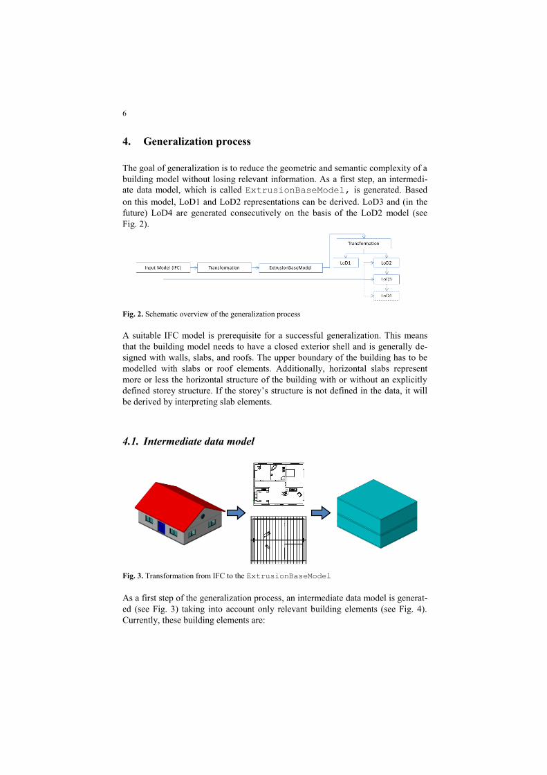
4. Generalization process
The goal of generalization is to reduce the geometric and semantic complexity of a
building model without losing relevant information. As a first step, an intermedi-
ate data model, which is called ExtrusionBaseModel, is generated. Based
on this model, LoD1 and LoD2 representations can be derived. LoD3 and (in the
future) LoD4 are generated consecutively on the basis of the LoD2 model (see
Fig. 2).
Fig. 2. Schematic overview of the generalization process
A suitable IFC model is prerequisite for a successful generalization. This means
that the building model needs to have a closed exterior shell and is generally de-
signed with walls, slabs, and roofs. The upper boundary of the building has to be
modelled with slabs or roof elements. Additionally, horizontal slabs represent
more or less the horizontal structure of the building with or without an explicitly
defined storey structure. If the storey‟s structure is not defined in the data, it will
be derived by interpreting slab elements.
4.1. Intermediate data model
Fig. 3. Transformation from IFC to the ExtrusionBaseModel
As a first step of the generalization process, an intermediate data model is generat-
ed (see Fig. 3) taking into account only relevant building elements (see Fig. 4).
Currently, these building elements are:

7
Walls (IfcWall, IfcWallStandardCase)
Slabs (IfcSlab with PredefinedType undefined or set to FLOOR or
BASESLAB)
Roofs (IfcRoof, IfcSlab with PredefinedType set to ROOF)
Facades (IfcCurtainWall)
Beams and columns (IfcBeam, IfcColumn), optionally taken into account.
In IFC, different representation types are allowed and have to be considered for
the transformation process. To get a uniform geometry base for the whole process,
each considered building element is additionally represented by its footprint ge-
ometry. This is derived by a vertical projection of the original geometry into the x-
y plane of the model coordinate system (x,y,z) → (x,y,0).
Fig. 4. Semantic filtering of IFC data (left: original model; right: only IFCSLAB, IFCWALL,
IFCBEAM)
Based on these footprints, extrusion containers are calculated. Each container ag-
gregates information connected with a specific building element type taking into
account the building structure, if possible. An extrusion container includes rela-
tions to the original IFC building elements, minimum and maximum z coordi-
nates, the footprint geometry of the aggregated building elements, and further rel-
evant information for post-processing the data.
Additionally, extrusion containers for building storeys are generated. If possi-
ble, they are derived from the building structure and combined with information
from horizontal slab elements.
After completing the container generation, a collection of different extrusion
containers is prepared for further processes. At first, heuristic methods are used to
identify building components like, e.g., balconies, dormers or inner courtyards.
For the further generalization process, these structures may be eliminated or kept.
During a last refinement step, the collected extrusion containers are validated.
Identified overlaps are eliminated and, depending on constraints, containers can be
split or merged.

8
The final ExtrusionBaseModel is the basis for all further steps. Its ge-
ometry is stored with the relating IfcBuilding and IfcBuildingStorey
instances of the IFC model as an extra geometric representation.
4.2. Generation of the LoD1 model
Following the definition of CityGML (Gröger et al. 2012, Benner et al 2013), a
LoD1 model is a rough approximation of the original building model represented
in one vertical extrusion. In many cases, this is not sufficient to represent the exte-
rior shell of a building. Especially for landmarks, the shape should represent the
characteristics of such buildings.
Based on the ExtrusionBaseModel, different strategies are implemented
for the LoD1 generalization process. Depending on the strategy, building foot-
prints, wall footprints or slab footprints are used to determine one or more vertical
extrusions for the final LoD1 model (see also Section 5.2).
The first strategy calculates one extrusion for the whole building. Thereby, all
footprints of the relevant building elements are used. The second variant focuses
on walls. In this case, footprints of walls on same levels and same heights are
combined and extruded. In the third case, footprints of horizontal slabs are used to
create the extrusion geometries.
Because the geometric representation of the ExtrusionBaseModel is very
close to the requirements of a LoD1 model (see Fig. 5), the main task of this trans-
formation step is to adjust the vertical extrusions for the requested generation
strategy. Optionally, it is also possible to create the resulting LoD1 geometries by
an explicit storey structure. This means that for each storey, an extra extrusion is
generated even if the footprints of the storeys are identical.
Fig. 5. Transformation ExtrusionBaseModel into a LoD1 model
4.3. Generation of the LoD2 model
Compared to LoD1, the generation process for LoD2 is completely different. The
basis is also the ExtrusionBaseModel but the generated outer contour of the

9
building is much more detailed with a correct roof shape and a detailed classifica-
tion of the outer boundary surfaces (see Fig. 6).
Fig. 6. Transformation ExtrusionBaseModel into a LoD2 model
The first step is to assign the roof shape. An algorithm was developed to generate
clipping planes for the extrusion containers of ExtrusionBaseModel, based
on the original geometry of the IFC building elements IfcRoof and IfcSlab
with PredefinedType set to ROOF. Supported geometry types in this process
are extrusion and B-rep.
For B-rep geometries, all face normals are analyzed in order to identify up-
wards pointing faces. The outer polygons of these faces are transformed into
bounded clipping planes.
For extrusion geometries, the procedure is different. Starting with the extrusion
placement, the extrusion direction and its magnitude, the top plane of the extruded
geometry can be calculated by a simple matrix operation. The boundary is derived
from the extrusion profile, which is transformed into the plane.
In the second step, building elements are used for a semantic classification of
the clipped extrusion geometries. For this, corresponding surfaces of IFC building
elements and ExtrusionBaseModel objects are identified. In the classifica-
tion mechanism, the following CityGML features are generated:
WallSurface
OuterFloorSurface
RoofSurface
GroundSurface
ClosureSurface
BuildingInstallation
While classifying the surfaces, an algorithm compares the distance of surfaces
from IFC building elements to the generated surfaces of the ExtrusionBase-
Model. The accuracy parameter epsilon for this distance test is adjustable, the
default value it is set to is 50 mm. If the distance is smaller than epsilon, the
corresponding surface is collected for further verifications. During this process,
several faces of one building element, but also faces of different building elements
can be found. All collected faces are compared in a second pass. In this pass, net

10
area and the quantity of overlapping area, with corresponding surfaces of the Ex-
trusionBaseMode are checked to assign the correct type.
As an optional calculation step, the generation of roof overhangs can be initiat-
ed. The relevant geometry will be derived by a geometrical comparison of IFC
roof elements with the created CityGML RoofSurface. By a projection of the
CityGML RoofSurface on the IFC roof geometries, the overlapping parts are
identified and separated by a geometric subtraction. For the CityGML model, the-
se geometries are currently classified as BuildingInstallation. Figure 7
shows the steps for extracting roof overhangs.
Fig. 7. a) IFC solid geometry, b) CityGML roof surface, c) Subtraction of the roof surface with
the top face of the IFC solid geometry, d) Resulting geometry for roof overhangs
4.4. Generation of the LoD3 model
The transformation process from a LoD2 model to a LoD3 model mainly differs in
applying voids for doors, windows, and openings and creating the appropriate el-
ements (see Fig. 8). In this step, the ExtrusionBaseModel is no longer used.
Fig. 8. Transformation of a LoD2 into a LoD3 model
This process is realized by interpreting the relations of IFC. Cutouts are not ex-
plicitly given in the IFC geometry representations, but defined as relations be-
tween building elements, voiding elements, and a door or window elements. The
first relation (IfcRelVoidsElement) describes a Boolean subtraction be-
tween, e.g., a wall and an opening element. Without handling this relation, the
wall is given by their gross volume. The second relation (IfcRelFillsEle-
ment) is to place a door or window element within the hole of the subtracted
opening element.
a) b) c) d)

11
Doors and windows in IFC can be represented geometrically in different ways.
Either by an explicit geometric representation, or by parameters describing opera-
tion type, lining, and panel. For non-rectangular elements, additionally a 2D pro-
file should be given to describe the outer contour of the door or window. If only
the parameters are given, the resulting geometry has to be calculated. Within the
generalization process, the best solution to control the geometric complexity of
these elements is to interpret the parameters, if available. Otherwise the geometry
will be approximated by a projection of the opening element on the corresponding
surface of the building element.
Unlike IFC, the opening elements in CityGML do not represent an additional
element, but are already subtracted from the corresponding boundary surface. The
door and window elements are defined as sub elements of the boundary surface
and are geometrically located within the boundary surface. Openings without a
door or window have to be represented as a ClosureSurface and cannot be
related to any boundary surface.
For doors and windows, it is sufficient to reduce their geometry by a surface.
This is different for embrasures. For representing a detailed façade, it is important
to have the detailed depth and contour of the embrasures. Similar to roof over-
hangs, it is possible to activate the embrasure generation optionally. This step is
currently under development. Basis is the IfcOpeningElement and the sim-
plified door or window elements, created in the previous step. Clipping planes are
derived from the door or window elements and from the boundary surface, e.g.,
WallSurface. Performing clipping operations with the geometry of the
IfcOpeningElement results in a solid (negative mold of the embrasure), fill-
ing the recess between door or window surface and top edge of the boundary sur-
face. Hence, the planes‟ normals are known, unneeded faces can be identified, and
the remaining faces have to be inverted. The whole process is shown in Figure 9.
Finally, the surfaces of the embrasure have to be defined by the type of the bound-
ary surface.
a)
b)
c)
d)
Fig. 9. a) IFC wall with window element, b) CityGML WallSurface with window element in
wall plane, c) CityGML WallSurface with window element at correct position and IFC open-
ing element (transparent), d) Embrasure realized by clipping opening element at wall and win-
dow plane
12
5. Testing and evaluation
The methodology described above is implemented as an early prototype in the
software platform IFCExplorer, which is developed at the Institute for Applied
Computer Science at Karlsruhe Institute of Technology. The IFCExplorer is a tool
for visualization, analysis, transformation, and integration of spatial data from dif-
ferent applications by open standardized data formats (e.g. IFC, cityGML,
gbXML). Different data models and application areas are supported and can be
opened either based on files or via standardized OGC web services (e.g. Web Fea-
ture Service, Web Map Service). For analyzing the different data models, a wide
range of checking functionalities is available. The implemented functionality
ranges from semantic validation, checking correctness of attributes, to geometrical
and mathematical checks. This is the basis for realization of the here described
generalization process (Benner et al. 2013b).
In order to prove the concept, single-family houses were used and transformed.
The generated LoD models are internally represented as CityGML models and can
be exported as CityGML 2.0 instance documents.
Each model is presented by an image of the IFC model and three images of the
transformed LoD1, LoD2, and LoD3 model. Furthermore, for each model, a table
shows all elements with a geometric representation, the types of the geometric
representations, and the total amount of faces used for rendering.
13
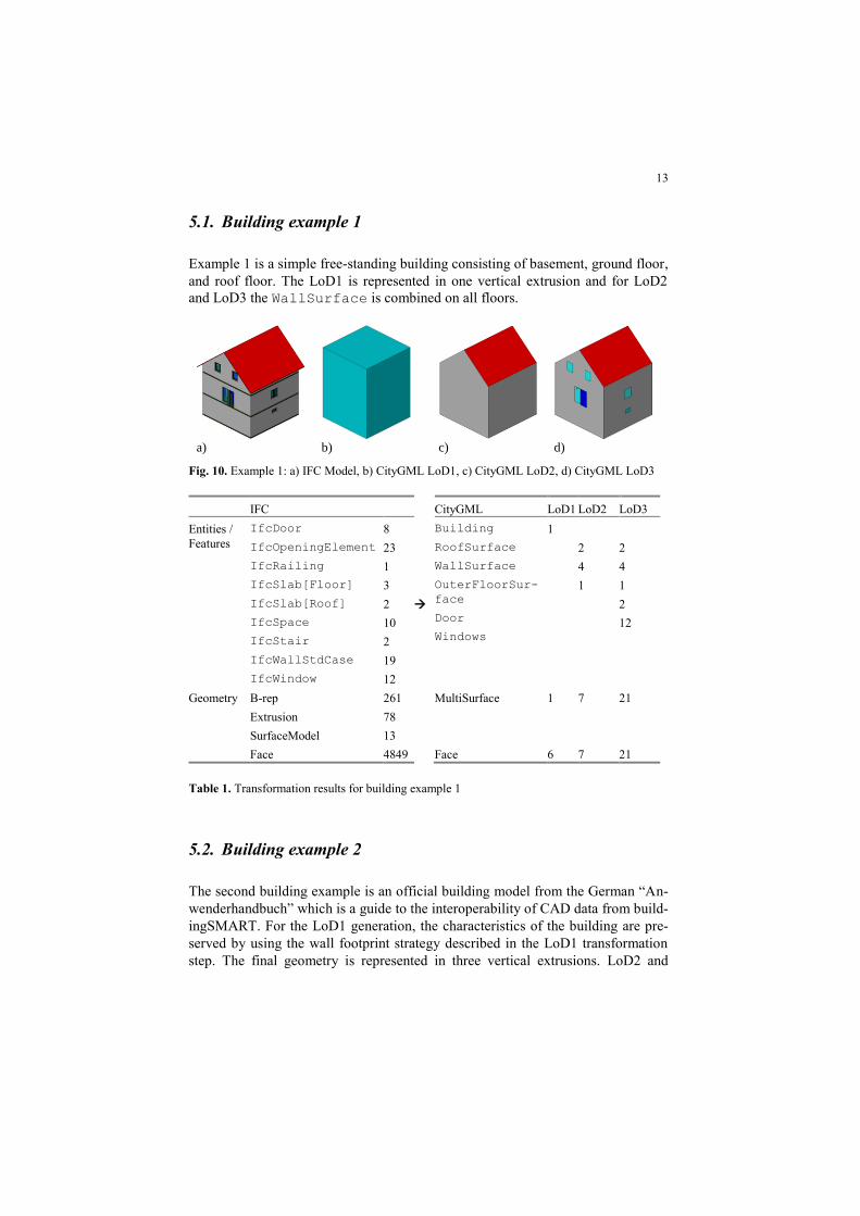
5.1. Building example 1
Example 1 is a simple free-standing building consisting of basement, ground floor,
and roof floor. The LoD1 is represented in one vertical extrusion and for LoD2
and LoD3 the WallSurface is combined on all floors.
a) b) c) d)
Fig. 10. Example 1: a) IFC Model, b) CityGML LoD1, c) CityGML LoD2, d) CityGML LoD3
IFC CityGML LoD1 LoD2 LoD3
Entities /
Features
IfcDoor
IfcOpeningElement
IfcRailing
IfcSlab[Floor]
IfcSlab[Roof]
IfcSpace
IfcStair
IfcWallStdCase
IfcWindow
8
23
1
3
2
10
2
19
12
Building
RoofSurface
WallSurface
OuterFloorSur-
face
Door
Windows
1
2
4
1
2
4
1
2
12
Geometry B-rep
Extrusion
SurfaceModel
261
78
13
MultiSurface 1 7 21
Face 4849 Face 6 7 21
Table 1. Transformation results for building example 1
5.2. Building example 2
The second building example is an official building model from the German “An-
wenderhandbuch” which is a guide to the interoperability of CAD data from build-
ingSMART. For the LoD1 generation, the characteristics of the building are pre-
served by using the wall footprint strategy described in the LoD1 transformation
step. The final geometry is represented in three vertical extrusions. LoD2 and

14
LoD3 are generated with the same options, for this reason the WallSurface on
ground floor and first floor are combined.
Due to an error in the internal Boolean operations, two of the window elements
in the LoD3 model are missing in the front façade. The window elements are iden-
tified and created in the CityGML instance document but the geometric represen-
tation is missing.
a) b) c) d)
Fig. 11. “Anwenderhandbuch”: a) IFC Model, b) CityGML LoD1, c) CityGML LoD2, d)
CityGML LoD3
IFC CityGML LoD1 LoD2 LoD3
Entities /
Features
IfcBeam
IfcDoor
IfcOpeningElement
IfcRailing
IfcSlab[BaseSlab]
IfcSlab[Floor]
IfcSlab[Roof]
IfcSpace
IfcStair
IfcWallStdCase
IfcWindow
17
21
60
8
1
3
2
21
6
38
36
Building
RoofSurface
WallSurface
FloorSurface
GroundSurface
Door
Windows
1
1
12
2
1
1
12
2
1
4
36
Geometry B-rep
Extrusion
1089
126
MultiSurface 1 16 56
Face 17426 Face 16 16 56
Table 2. Transformation results for building example 2

15
6. Summary and outlook
In order to use architectural building models like IFC in other application domains
like geospatial environments or energy calculation, a method for semantical and
geometrical generalization of IFC models is introduced. As a first example of this
process, the transformation from IFC to CityGML (LoD1, 2, 3) is explained and
first results are shown.
The method is implemented as an early prototype in the software IFCExplorer.
The process is performed interactively and needs no further input. The results are
immediately shown in the same document as the IFC model, which allows a direct
comparison between the models. Tests have been carried out with simple single-
family houses.
Next steps are implementing a prototype which can handle more complex
buildings then single-family houses. This prototype will also include the consider-
ation of overhanging parts of the building and the building‟s interior.
With these experiences, the generalization process will be extended regarding
other requirements for energy performance simulation. In this case, single-zone -
or multi-zones models will be created and exported to gbXML (gbXML 2014).
7. References
AIA (2013) Level of Development Specification Version: 2013, Available at
http://bimforum.org/wp-content/uploads/2013/08/2013-LOD-Specification.pdf. Accessed Ju-
ly 2, 2014.
Babic, B., Nesic, N., Miljkovic, Z. (2008) A review of automated feature recognition with rzle-
based pattern recognition. Computers in Industry 59(4), 321-337.
Baig, S.U., Rahmann, A.A. (2013) A unified approach for 3D generalization of building models
in CityGML. International Archives of the Photogrammetry, Remote Sensing and Spatial In-
formation Sciences, XL-4/W1, 93-99.
Benner, J., Geiger, A., Gröger, G., Häfele, K.-H., Löwner, M.-O. (2013a) Enhanced LoD Con-
cepts for virtual 3D City Models. 8th 3D GeoInfo Conference, Instanbul, 2013.
Benner, J., Geiger, A., Häfele, K.-H., Knüppel, H. (2013b) IFCExplorer – Ein Werkzeug für die
Integration unterschiedlicher raumbezogener semantischer Daten. Geoinformatik, Heidel-
berg, 2013.
bSI (2014) Available at http://www.buildingsmart.org/. Accessed June 25, 2014.
van Berlo, L., (2011) Integration of BIM and GIS: The development of the CityGML GeoBIM
extension. Advances in 3D Geo-Information Sciences.
Cheng, J., Deng, Y., Du, Q. (2013) Mapping between BIM models and 3D GIS city models of
different Levels of Detail. 13th International Conference on Construction Applications of
Virtual Reality, 30-31 October 2013, London, UK.
Cox, S., Daisey, P., Lake, R., Portele, C., Whiteside, A. (2004) OpenGIS® Geography Markup
Language (GML) Implementation Specification, Version: 3.1.1, OGC 03-105r1, Open Geo-
spatial Consortium, 2004.
Donkers, S. (2013) Automatic generation of CityGML LoD3 building models from IFC models.
MSc Thesis, Delft University of Technology, 2013.

16
El-Mekawy, M., Östman, A., Hijazi, I. (2012) An Evaluation of IFC-CityGML Unidirectional
Conversion. International Journal of Advanced Computer Science and Application, Vol. 3,
No. 5, 2012.
Eastman, C. M. (1999) Building Product Models: Computer Environments Supporting Design
and Construction, CRC Press.
Fan, H., Meng, L. (2012) A three-step approach of simplifying 3D buildings modeled by
CityGML. International Journal of Geographic Information Science 26(6), 1091-1107.
gbXML (2014) Available at http://www.gbxml.org/. Accessed June 25, 2014.
Gröger, G., Kolbe, T.H., Nagel, C., Häfele, K.-H. (2012) OGC City Geography Markup Lan-
guage (CityGML) Encoding Standard, Version 2.0, OGC Doc No. 12-019, Open Geospatial
Consortium, 2012.
ICA 1973 International Cartographic Association, Multilingual Dictionary of Technical Terms in
Cartography, Franz Steiner Verlag, 1973.
ISO 10303-11:2004 Industrial automation systems and integration -- Product data representation
and exchange -- Part 11: Description methods: The EXPRESS language reference manual,
2004.
ISO 10303-21:2002 Industrial automation systems and integration -- Product data representation
and exchange -- Part 21: Implementation methods: Clear text encoding of the exchange struc-
ture, 2002.
ISO 10303-28:2007 Industrial automation systems and integration -- Product data representation
and exchange -- Part 28: Implementation methods: XML representations of EXPRESS sche-
mas and data, using XML schemas, 2007.
ISO 16739:2013 Industry Foundation Classes (IFC) for data sharing in the construction and fa-
cility management industries, 2013.
ISO19107:2003 Geographic information -- Spatial schema, 2003.
Kada, M. (2002) Automatic generalization oof 3D building models. International Archives of
Photogrammetry, Remote Sensing and Spatial Information Sciences 34 (Part 4), 243-248.
Kada, M. (2006) 3D Building Generalization based on Half-Space Modeling. In: Proceedings of
the ISPRS Workshop on Multiple Representation and Interoperability of Spatial Data, Han-
nover, Germany.
Liebich, T. (2007) Industry Foundation Classes - IFC2x3 Documentation, 2007.
Luebke, D., Reddy, M., Cohen, J.D., Varshney, A., Watson, B., Huebner, R. (2003) Level of De-
tail for 3D Graphics. Morgan Kaufmann, San Francisco.
Meng, L., Forberg, A. (2006) 3D building generalization. In: Mackaness, W., Ruas, A., Sarjako-
ski, T. (Eds.), Challenges in the Portrayl of Geographic Information: Issues of Generalisation
and Multi Scale Representation. Elsevier Ltd., 211-232.
Nagel, C. (2006) Ableitung verschiedener Detailierungsstufen von IFC Gebäudemodellen. MSc
Thesis, University of Applied Science Karlsruhe / Research Center Karlsruhe, 2006.
Nagel, C., Häfele, K.-H. (2007) Generierung von 3D-Stadtmodellen auf Basis des IFC-
Gebäudemodells. Entwicklerforum Geoinformatinstechnik 2007.
Sester, M. (2007) 3D Visualization and Generalization. In: Proceedings of the 51st Photogram-
metric Week, Stuttgart, Germany, 3-7 September, 285-295.
Thakura, A., Banerjeea, A.G., Gupta, S.K. (2009) A survey of CAD model simplification tech-
niques for physics-based simulation applications. Computer-Aided Design 41 (2), 65-80.
Thiemann, F., Sester, M. (2004) Segmentation of buildings for 3D-generalisation. Proceedings of
the 7th ICA Workshop on Generalisation and Multiple Representation, Leicester, UK, 20-21
August (on CD-ROM).