A GENERALIZATION APPROACH FOR 3D VIEWING DEFORMATIONS OF SINGLE-CENTER...
8
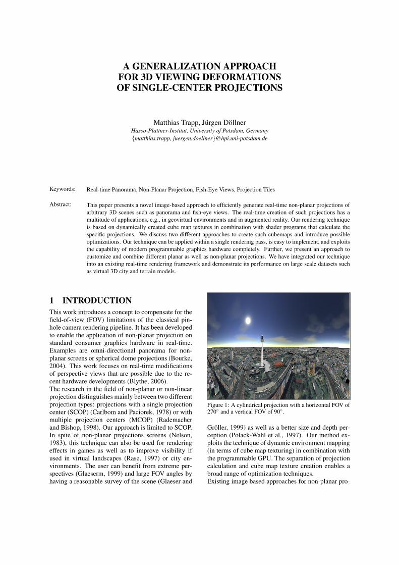
A GENERALIZATION APPROACH FOR 3D VIEWING DEFORMATIONS OF SINGLE-CENTER PROJECTIONS Matthias Trapp, J¨ urgen D¨ ollner Hasso-Plattner-Institut, University of Potsdam, Germany {matthias.trapp, juergen.doellner}@hpi.uni-potsdam.de Keywords: Real-time Panorama, Non-Planar Projection, Fish-Eye Views, Projection Tiles Abstract: This paper presents a novel image-based approach to efficiently generate real-time non-planar projections of arbitrary 3D scenes such as panorama and fish-eye views. The real-time creation of such projections has a multitude of applications, e.g., in geovirtual environments and in augmented reality. Our rendering technique is based on dynamically created cube map textures in combination with shader programs that calculate the specific projections. We discuss two different approaches to create such cubemaps and introduce possible optimizations. Our technique can be applied within a single rendering pass, is easy to implement, and exploits the capability of modern programmable graphics hardware completely. Further, we present an approach to customize and combine different planar as well as non-planar projections. We have integrated our technique into an existing real-time rendering framework and demonstrate its performance on large scale datasets such as virtual 3D city and terrain models. 1 INTRODUCTION This work introduces a concept to compensate for the field-of-view (FOV) limitations of the classical pin- hole camera rendering pipeline. It has been developed to enable the application of non-planar projection on standard consumer graphics hardware in real-time. Examples are omni-directional panorama for non- planar screens or spherical dome projections (Bourke, 2004). This work focuses on real-time modifications of perspective views that are possible due to the re- cent hardware developments (Blythe, 2006). The research in the field of non-planar or non-linear projection distinguishes mainly between two different projection types: projections with a single projection center (SCOP) (Carlbom and Paciorek, 1978) or with multiple projection centers (MCOP) (Rademacher and Bishop, 1998). Our approach is limited to SCOP. In spite of non-planar projections screens (Nelson, 1983), this technique can also be used for rendering effects in games as well as to improve visibility if used in virtual landscapes (Rase, 1997) or city en- vironments. The user can benefit from extreme per- spectives (Glaeserm, 1999) and large FOV angles by having a reasonable survey of the scene (Glaeser and Figure 1: A cylindrical projection with a horizontal FOV of 270 ◦ and a vertical FOV of 90 ◦ . Gr¨ oller, 1999) as well as a better size and depth per- ception (Polack-Wahl et al., 1997). Our method ex- ploits the technique of dynamic environment mapping (in terms of cube map texturing) in combination with the programmable GPU. The separation of projection calculation and cube map texture creation enables a broad range of optimization techniques. Existing image based approaches for non-planar pro-
Transcript of A GENERALIZATION APPROACH FOR 3D VIEWING DEFORMATIONS OF SINGLE-CENTER...
A GENERALIZATION APPROACHFOR 3D VIEWING DEFORMATIONSOF SINGLE-CENTER PROJECTIONS
Matthias Trapp, Jurgen DollnerHasso-Plattner-Institut, University of Potsdam, Germany{matthias.trapp, juergen.doellner}@hpi.uni-potsdam.de
Keywords: Real-time Panorama, Non-Planar Projection, Fish-Eye Views, Projection Tiles
Abstract: This paper presents a novel image-based approach to efficiently generate real-time non-planar projections ofarbitrary 3D scenes such as panorama and fish-eye views. The real-time creation of such projections has amultitude of applications, e.g., in geovirtual environments and in augmented reality. Our rendering techniqueis based on dynamically created cube map textures in combination with shader programs that calculate thespecific projections. We discuss two different approaches to create such cubemaps and introduce possibleoptimizations. Our technique can be applied within a single rendering pass, is easy to implement, and exploitsthe capability of modern programmable graphics hardware completely. Further, we present an approach tocustomize and combine different planar as well as non-planar projections. We have integrated our techniqueinto an existing real-time rendering framework and demonstrate its performance on large scale datasets suchas virtual 3D city and terrain models.
1 INTRODUCTIONThis work introduces a concept to compensate for thefield-of-view (FOV) limitations of the classical pin-hole camera rendering pipeline. It has been developedto enable the application of non-planar projection onstandard consumer graphics hardware in real-time.Examples are omni-directional panorama for non-planar screens or spherical dome projections (Bourke,2004). This work focuses on real-time modificationsof perspective views that are possible due to the re-cent hardware developments (Blythe, 2006).The research in the field of non-planar or non-linearprojection distinguishes mainly between two differentprojection types: projections with a single projectioncenter (SCOP) (Carlbom and Paciorek, 1978) or withmultiple projection centers (MCOP) (Rademacherand Bishop, 1998). Our approach is limited to SCOP.In spite of non-planar projections screens (Nelson,1983), this technique can also be used for renderingeffects in games as well as to improve visibility ifused in virtual landscapes (Rase, 1997) or city en-vironments. The user can benefit from extreme per-spectives (Glaeserm, 1999) and large FOV angles byhaving a reasonable survey of the scene (Glaeser and
Figure 1: A cylindrical projection with a horizontal FOV of270◦ and a vertical FOV of 90◦.
Groller, 1999) as well as a better size and depth per-ception (Polack-Wahl et al., 1997). Our method ex-ploits the technique of dynamic environment mapping(in terms of cube map texturing) in combination withthe programmable GPU. The separation of projectioncalculation and cube map texture creation enables abroad range of optimization techniques.Existing image based approaches for non-planar pro-

jections suffer mainly from the lack of interactive ca-pabilities if used with complex geometric scenes suchas virtual 3D city models or for large viewports. Thiscan be explained by the trade-off between the gener-ality of the proposed frameworks and their efficientreproduction. Furthermore, the parameterizations arecomplex and cannot be controlled by the user intu-itively (Brosz et al., 2007).Our approach was inspired by (van Oortmerssen,2002). This CPU-based technique renders six viewsof FOV 90 in each direction. Afterwards, a table isused to transform these pixels to one single view ac-cording to fisheye and panorama projections.Our main contribution consists of a simple parame-terizable approach to combine planar as well as non-planar projections seamlessly via so-called projectiontiles. Therefore we introduce an efficient image-basedcreation method for non-planar projections that canbe applied in a single rendering pass. Our renderingtechnique fully exploits current programmable con-sumer graphics hardware. The presented concept iseasy to implement into existing rendering real-timeframeworks and can be combined with other tech-niques that modify the image synthesis.The paper is structured in the following way: Section2 describes the related work. Chapter 3 describes thebasic concept of our approach whilst Section 4 intro-duces a novel generalization schema for non-planarprojections. Section 5 explains the implementationdetails. Section 6 presents possible results and appli-cations as well as discusses the performance and lim-itations of our rendering technique. Section 7 showsideas for future work and Section 8 draws some con-clusions.
2 RELATED WORKThis section gives an overview of research in the fieldsof SCOP and MCOP projections. There is a vastamount of literature covering foundations and appli-cations of non-planar as well as non-linear projec-tions. In (Brosz et al., 2007) a sophisticated overviewis presented.
2.1 SCOP ApproachesTo achieve distortions or special projections of the3D scene, the pinhole camera is extended in severalways. In (Bayarri, 1995) a procedure is proposed thatis based on the computation of new absolute coordi-nates to be transformed through an adaptive projec-tion matrix. A flexible adaptive projection frameworkis described by Brosz et.al. (Brosz et al., 2007) thatenables the modeling the modeling of linear, non-linear, and hand-tailored artistic projections. It uses
ray-casting and scanline rendering algorithm wherepolygonal coordinates are changed by a vertex shader.The generality of the framework makes efficient pro-jection difficulty, especially for large scale scenes.Distortions as sub-category of geometric registrationor image warping are discussed in (Gustafsson, 1993)and (Glasbey and Mardia, 1989). A warping func-tion is applied to each pixel to determine its new colorvalue.An image stitching approach for panorama imagegeneration can be found in (Szeliski and Shum,1997). In (Turkowski, 1999) a method is demon-strated to generate environment maps from fisheyephotographs. Besides the issues of nonlinear perspec-tive deformation described in (Yang et al., 2005; H.et al., 1999; Yang et al., 2003; Bourke, 2000; Swami-nathan et al., 2003) we find also lens taxonomies(Neumann and Carpendale, 2003; Leung and Apper-ley, 1994). These approaches use a regular mesh tex-tured with a 2D texture that contains the renderedscene or an image. The displacement of the mesh ver-tices together with the texture mapping process gener-ates the particular distortion effect. These approachesare limited regarding the FOV which can be achieved.Carpendale researched the usage of image defor-mation in the context of information visualization(Carpendale and Montagnese, 2001). The applicationof fisheye views in information visualization is dis-cussed in (Rase, 1997). Applications for view distor-tions in ray-tracing software are described in (Grollerand Acquisto, 1993; Coleman and Singh, 2004).
2.2 MCOP ApproachesAdditional to SCOP imaging there are non-planarprojection surfaces that require multiple perspectives,e.g., a number of images from different center of pro-jections (Wood et al., 1997). The goal is to keepqualities of global scene coherence, local distortions,and shading results from the changes in perspectiveof each projection. View-independent rendering, ex-pressive CG imagery or animation are just a few ap-plications for this area of scientific research.Apart from slit cameras, (Glassner, 2000) introducedthe Cubist Camera that presents many interpretationsand points of view simultaneously. The techniqueuses nonlinear ray tracing that handles lighting butcan cause artifacts.Given a scene geometry and an UI to position localand master cameras (Agrawala et al., 2000), Artis-tic Multiprojection Rendering provides a tool for cre-ating multi-projection images and animations. Theprincipal item is the algorithm that solves occlusionsof the scene objects, each rendered by a local cam-era. This is able to handle fixed distortions and cre-

A B C
Figure 2: Comparison between a classical perspective projection with a FOV of 45◦ (A) and a spherical projection with aFOV of 260◦ (B). Sub-figure (C) shows the same projection with an off-axis vector O = (0.8,0,0).
ates surrealistic, toony styles but cannot solve lightingand shadow problems.A fresh Perspective (Singh, 2002) introduces also aninteractive approach that does neither handle illumi-nation issues nor control global scene coherence. Thedifference: the resulting nonlinear perspective imageof an object is potentially influenced by all cameras.Constitutive on that is RYAN (Coleman and Singh,2004). This interactive system integrates into the con-ventional animation work flow. It distorts the scenegeometry prior to the linear perspective transforma-tion. The result will appears nonlinearly projected.Just like (Agrawala et al., 2000), it uses two kindsof cameras: boss (traditional linear perspective) andlackey (represent local linear views). The illumina-tion is done by blending illumination of boss andlackey cameras or setting a single view point for light-ing.
3 BASIC CONCEPTThe concept of our approach is based on two com-ponents: a dynamic environment map (Heidrichand Seidel, 1998) and fragment shader functionality(NVIDIA, 2005). First, the virtual environment isrendered into a cube map texture. The cube map tex-ture is a fully hardware accelerated feature (NVIDIA,2004) and can be constructed by using single or multi-pass rendering (see Section 5.1).To derive a non-planar projection, we have to deter-mine a cube map sampling vector S = (x,y,z) ∈ D3
for each fragment Fst = (s, t) ∈ D2. Formally, we de-fine a projection function δP (Fst) = S for a projectionP as:
δP : D2 −→ D3 (s, t) 7−→ (x,y,z)
Where D = [−1;1] ⊂ R is a normalized coordinatespace. For example, a horizontal cylindrical projec-tion C can be formulated as instance δC (Fst ,α,β) = Swith an horizontal FOV of 2 ·α and a vertical FOV of2 ·β :
x = cos(s ·α) y = t · tan(β) z = sin(s ·α)
Further, a spherical projection S with an FOV of γ canbe expressed as δS (Fst ,γ) = S with:
x = sin(θ) · cos(φ)y = sin(θ) · sin(φ)z = cos(θ)
φ = arctan(t,s)θ =
√s2 + t2 · γ/2
This procedure assumes an user orientation towardsthe negative z-axis. If the cube map texture is createdin the standard orientation (Figure 3.A), we wouldhave to correct S by transforming it with respect tothe current camera parameters. The transformationmatrix C is an orthonormal base constructed from thecurrent look-to vector LT = (xT ,yT ,zT )∈D3, look-upvector LU = (xU ,yU ,zU ) ∈ D3 and the cross productLC = (xC,yC,zC) = LT ×LU so that:
C =
xT yT zTxU yU zUxC yC zC
⇐⇒ LT •LU 6= 0
Following this, the final sampling vector V for a pro-jection P and a fragment Fst is calculated via:
V =(C ·δP (Fst · s)
)−O
The vector O ∈ D3 is denoted as off-axis vector(Bourke, 2004). Figure 2.C demonstrates an exam-ple for an off-axis projection. The scalar term s ∈ Dcan be interpreted as a zooming parameter.To avoid unnecessary calculations at runtime, the dis-tortion vector V can be stored into a high-precisionfloating-point normal map (Kilgard, 2004). This re-duces the shader execution costs for projection calcu-lation to two texture look-up operations and enables anew technique for combining different projection us-ing projection tiles.
Figure 3: Standard cube map orientation used by our con-cept and implementation.

D
Cst
Cst = fsample(Nst )Nst = fnormal(Ast )i,j: frender(Tij )
C
Nst
A
T11
E12
E11
E22
E21
B
Ast
Tile Screen Feature Map Normal Map Final Rendering
Figure 4: Elaborated conceptual pipeline to render combinations of planar and non-planar projections defined by projectiontiles. A tile screen (A) is transformed into an angle map (B) from which a normal map (C) is derived that contains the cubemap sampling vector to create the final rendering (D).
4 PROJECTION TILESThis method enables the combination of planar pro-jections and different non-planar derivatives as well asit facilitates the creation of custom projections whichare hard to describe analytically. In this context, pro-jection tiles are a generalization of the concepts de-scribed in Section 3. They enable control over differ-ent projection types as well as add a smooth transitionof their parameters. A projection tile defines the areaof a specific projection in relation to the viewport.Projection tiles are organized in a projection tilescreen (PTS) (Figure 4.A). It is represented by a spe-cific feature set T mn defined as follows:
T mn =
E0n · · · Emn...
. . ....
E00 · · · Em0
A component Ei j of T mn is denoted as tile feature.It basically describes a view direction for a specificpoint on the screen. To enable a more intuitive way todescribe a tile screen, we have chosen spherical po-lar coordinates φ and θ to express the view directioninstead of a normalized direction vector. Thus, wedefine a feature Ei j as a 6-tupel:
Ei j = (xi j,yi j,eA(φi j),eA(θi j),si j, fi j)xi j,yi j,si j, fi j ∈ [0;1]⊂ R
φi j,θi j ∈ [−360;360]⊂ R
that contains the feature position (xi j,yi j) and the par-ticular horizontal and vertical view angles (φi j,θi j).The parameter si j is the respective scaling factor whilethe variable fi j can be used to bind custom parametersto each feature. Figure 5 demonstrates this by adjust-ing the image saturation according to the respect valueof f . The function eA(x) = (x + 360)/720 is used toencode an angle into a range of [0;1].The PTS is transformed into a feature map (Figure4.B) by rendering its respective tiles Tkl with k =0 . . .m−1, l = 0 . . .n−1:
Tkl = (E(k,l),E(k+1,l),E(k+1,l+1),E(k,l+1))
into a texture using render-to-texture (Wynn, 2002).The components xi j and yi j are interpreted as the 2Dvertices of a quad in standard orthographic parallelprojection (Woo et al., 1999). The angles and thescale factor are encoded into a per-vertex RGBA colorvalue. The hyperbolic interpolation (Blinn, 1992) be-tween these values is performed by graphics hard-ware.The rendered feature map stores the interpolated hor-izontal and vertical angles Ast = (φst ,θst) for eachfragment Fst . The normal Nst can be calculated by:
Nst = fnormal(Ast)
= Rx(e−1
A (θst))Ry
(e−1
A (φst))0
01
+
st0
Where Rx and Ry denote the 3D rotation around therespective axis. For each Nst in the resulting normalmap (Figure 4.C) a sampling vector S can be calcu-lated by setting δT mn(Fst · sst) = Nst . The result isshown in Figure 4.D.
5 IMPLEMENTATIONThe rendering of non-planar projections is performedin two steps per frame:
1. Create or update dynamic cube map as describedin Section 5.1. During this phase, optimizationmethods as described in Section 5.2 can be uti-lized.
2. Apply projections by exploiting programmablegraphics hardware (see Section 5.3) This step isapplied in postprocessing and requires an addi-tional rendering of the scene geometry.
The exemplary implementation was done by us-ing OpenGL (Segal and Akeley, 2004) in combina-tion with GLSL (John Kessenich, 2004). It usesframebuffer objects, floating point textures, and mip-mapped cube maps for dynamic texturing (Harris,2004).

A B
Figure 5: Examples for combining planar and non-planar projections within a single rendering using projection tile screens.Sub-figure A is composed of a planar projection in the center and cylindrical projections left and right. Sub-figure B shows thesame scene with two planar projections for each cathedral. The saturation falloff is controlled by the respective tile features.
5.1 Cube Map CreationAn advantage of our image-based concept is the appli-cation of dynamic cube map textures (Greene, 1986).The creation of those can be optimized depending onthe respective projections. This can be achieved usingtwo techniques:
Single-Pass Creation: On current hardware, it ispossible to create cube map textures within a singlepass by utilizing geometry shaders (Microsoft, 2007).This render-to-cube-map technique duplicates eachinput triangle six times and applies a separate model-view transformation for each face of the cube. Eachof the resulting triangles is directed to the appropriateelement of a render target array view of the cube map(Blythe, 2006)
Multi-Pass Creation: One can create a cube maptexture using multi-pass rendering in combinationwith render-to-texture (Goddeke, 2005). Given areference camera position, we can construct six localvirtual cameras with a FOV of 90 degrees, an aspectratio of 1, and render the scene into the respectivecube map texture targets.
We have two alternatives to construct these virtual lo-cal cameras: 1) by rotating the reference camera or 2)by using fixed cube map orientation (Figure 3). Thelatter demands for a look-to correction as described inSection 3 and is necessary for a simple implementa-tion of projection tiles.
5.2 Optimization TechniquesDepending on the scene complexity, the creation of acube map texture can become costly. Usually, the cre-ation is fill-limited due to the increased rasterizationeffort as well as bandwidth-limited due to the number
of rendering passes. In our application, it is not pos-sible to use proxy geometry to speed up the creationprocess or distribute the rendering of each cube mapface to different frames. We have implemented twomain optimization techniques that are able to com-pensate this problem.
CMF Optimization: This optimization omits theupdate of cube map faces (CMF) that are not visiblein the generated projection. To determine which cubemap faces have to be updated, we calculate 360 de-gree spherical coordinates for each corner vertex ofthe unit cube and the current look-to vector LT . Then,we define a non-planar view frustum (NVF) by off-setting the spherical coordinates of LT with the hori-zontal and vertical angle of the current projection. Ifone of the face vertices is inside the projection region,the associated face will be updated. Figure 6 demon-strates this by considering the lower vertices of theunit cube only. For the current look-to vector LT theupdate of CMFback is omitted.
(0,0,0)
(1,-1,1)
-z
x
(-1,-1,1)
(-1,-1,-1) (-1,-1,1)
LT
CMFback
CMFfront
CM
F lef
t
CM
F rig
ht
LTlowerleft
Non-Planar View Frustum (NVF)
Unit Cube
Unit Sphere LTlowerright
Projection Region
Figure 6: Parameter space for CMF-Optimization. Thecube map is displayed from the positive y-axis. The grayarea represents the non-planar view frustum of a non-planarprojection.

Figure 7: Example for applying postprocessing filters to theoutput of our projection technique. Together with a wideangle projection, the radial blur emphasizes the impressionof speed.
Look-To Optimization: Another optimizationmethod would omit the update of the cube maptexture if the camera position is not changed.A further optimization method can orient the cubemap in such way that an optimal coverage for therespective projection region can be achieved. Thisincludes changes in the projection function and is leftfor future work.
5.3 Applying ProjectionsThe projection is rendered in a post-processing passsubsequent to the cube map creation pass(es). It canbe performed according to the following steps:
1. Setup a standard 2D orthographic parallel projec-tion with le f t = bottom = 0 and right = top = 1.The camera is set to the standard orientation witha look-to vector LT = (0,0,−1).
2. Activate a specific fragment program that imple-ments the mathematical concepts as described inSections 3 and 4. Then, the shader program per-forms cube map texture lookups or outputs thecalculated normal vectors for later re-use.
3. Render a screen aligned quad with standard tex-ture coordinates that covers the entire screen. Toapply the described concepts, the fragment posi-tion (s, t) must be normalized in D.
6 RESULTSFigures 1 and 2 show the application of our approachfor the interactive visualization of large scale datasetssuch as 3D virtual city models. Currently, we did notapply our method to scenes made of real-world im-ages. However, this is possible because our technique
128,0 256,0 512,0 1024,0FPS 1 23,3 12,7 8,7 7,8FPS 2 18,3 10,9 5,1 3,2FPS 3 9,7 7,7 5,9 4,1
0
5
10
15
20
25
128 256 512 1024
Cube Map Resolution
FPS
Model 1Model 2Model 3
Figure 8: Performance measurements for different modelsand cube map texture resolutions.
is independent from the scene representation. Fig-ure 7 demonstrates the combination of our renderingtechnique together with color post-processing filters.Figure 9 shows the application to projection systems.Here, the pincushion distortion is compensated by theprojectors.
Performance: Figure 8 shows the measured framerate for 3 models of different polygon counts. Themeasurements were taken on NVIDIA GeForce 8800GTX GPU with 786MB RAM and AthlonTM62 X2Dual Core 4200+ with 2.21 GHz and 2 GB of mainmemory at a viewport resolution of 1600x1200 pixel.It uses multi-pass rendering to create the cube maptexture. The test application does not utilize the sec-ond CPU core. The most complex sample dataset(Model 1) comprises the inner city of Berlin withabout 16,000 generically textured buildings, about100 landmarks, and a 3 GB color aerial photo on topof a digital terrain model.
Limitations: The observable subside of the framebetween the cube map resolution 512 and 1024 pixelis caused by a fill limitation of the used graphics hard-ware and can vary. The necessary resolution of thecube map texture depends on the resolution of theviewport and the used projection. For high horizon-tal and vertical FOV, a cube map resolution of 10242
pixels is sufficient in most cases.The quality of the feature map depends on the res-olution of the PTS. If the resolution is too low, thefeature interpolation can cause artifacts for tiles withacute angles. We obtained blurred output images forextreme FOV. This is the key disadvantage of our ap-proach and is caused by texture sampling artefacts.

Figure 9: This is an example for the application of our ren-dering technique to a cylindrical projection wall with a di-ameter of 4 meters. It uses a static, pre-rendered cube maptexture.
7 FUTURE WORK
Although our approach performs as expected, thereare still possibilities for further improvements. Theadaption of cube map optimization techniques to thesingle pass creation technique as well as experimentswith irregular texture resolutions are left for futurework. To compensate for unsharp output images weare up to develop custom filtering methods for cubemap textures.We are particularly interested in supporting otherSCOP projections as described in (Margaret, 1995).The representation of standard non-planar projectionsusing tile screens enables the combination of non-planar projections with the 2D lens metaphor as de-scribed in (Spindler et al., 2006; Carpendale andMontagnese, 2001) as well as (Bier et al., 1993).Therefore, a authoring tool for PTS is necessary. Fur-ther, we try to adapt our rendering technique to gen-erate non-planar for 3D anaglyph images.Additionally, we can apply the isocube approach(Wan et al., 2007) to compensate cube map samplingartifacts for lower resolutions. Finally, a comparativeperformance evaluation concerning time efficiency ofour concept compared to other approaches is left forfuture work.
8 CONCLUSIONS
We have presented an approach to generate non-planar projections for real-time applications. We sug-gested optimization methods to accelerate the cre-ation of dynamic environment maps and introduced anovel approach for creating combined SCOP projec-tions. We demonstrated the results and performanceof our rendering technique by integrating it into anexisting rendering framework (3Dgeo, 2007).
ACKNOWLEDGEMENTSThis work has been funded by the German FederalMinistry of Education and Research (BMBF) as partof the InnoProfile research group ’3D Geoinforma-tion’ (http://www.3dgi.de). The authors would liketo thank also 3D geo for providing the texture data aswell as the cadastral data of virtual 3D city models.
REFERENCES3Dgeo (2007). LandXplorer. http://www.3dgeo.de.
Agrawala, M., Zorin, D., and Munzner, T. (2000). Artis-tic Multiprojection Rendering. In 11th EurographicsWorkshop on Rendering, pages 125–136, Brno, CzechRepublic.
Bayarri, S. (1995). Computing Non-Planar Perspectives inReal Time. Computers & Graphics, 19(3):431–440.
Bier, E. A., Stone, M. C., Pier, K., Buxton, W., and DeRose,T. D. (1993). Toolglass and Magic Lenses: TheSee-Through Interface. In SIGGRAPH, pages 73–80.ACM Press.
Blinn, J. (1992). Hyperbolic Interpolation. IEEE ComputerGraphics and Applications Staff, 12(4):89–94.
Blythe, D. (2006). The Direct3D 10 System. In SIGGRAPH’06: ACM SIGGRAPH 2006 Papers, pages 724–734,New York, NY, USA. ACM Press.
Bourke, P. (2000). Nonlinear Lens Distortion.
Bourke, P. (2004). Offaxis Fisheye Projection.
Brosz, J., Samavati, F. F., Sheelagh, M., Carpendale, T., andSousa, M. C. (2007). Single Camera Flexible Pro-jection. In NPAR ’07: Proceedings of the 5th inter-national symposium on Non-photorealistic animationand rendering, pages 33–42, New York, NY, USA.ACM Press.
Carlbom, I. and Paciorek, J. (1978). Planar Geometric Pro-jections and Viewing Transformations. ACM Comput.Surv., 10(4):465–502.
Carpendale, M. S. T. and Montagnese, C. (2001). A Frame-work for Unifying Presentation Space. In UIST ’01:Proceedings of the 14th annual ACM symposium onUser interface software and technology, pages 61–70,New York, NY, USA. ACM Press.
Coleman, P. and Singh, K. (2004). RYAN: Rendering YourAnimation Nonlinearly projected. In NPAR.
Glaeser, G. and Groller, E. (1999). Fast Generation ofCurved Perspectives for Ultra-Wide-Angle Lenses inVR Applications. The Visual Computer, 15(7/8):365–376.
Glaeserm, G. (1999). Extreme and Subjective Perspectives.In Topics in Algebra, Analysis and Geometry, pages39–51, BPR Mdiatancsad BT/Budapest.
Glasbey, C. and Mardia, K. (1989). A Review of Im-age Warping Methods. Journal of Applied Statistics,25:155–171.
Glassner, A. S. (2000). Cubism and Cameras: Free-formOptics for Computer Graphics. Technical report, Mi-crosoft Research.
Goddeke, D. (2005). Playing Ping Pong with Render-To-Texture. Technical report, University of Dortmund,Germany.
Greene, N. (1986). Environment Mapping and other Ap-plications of World Pojections. IEEE Comput. Graph.Appl., 6(11):21–29.
Groller, M. E. and Acquisto, P. (1993). A Distortion Camerafor Ray Tracing. In Conner, Hernandez, Murthy, andPower, editors, Visualization and Intelligent Design inEngineering and Architecture. Elsevier Science Pub-lishers.
Gustafsson, A. (1993). Interactive Image Warping. Master’sthesis, Faculty of Information Technology.
H., B., J., Y., and Q., P. (1999). Non-Linear View Interpo-lation. In The Journal of Visualization and ComputerAnimation, volume 10, pages 233–241(9). John Wiley& Sons, Ltd.
Harris, M. (2004). Dynamic Texturing. NVIDIA Corpora-tion.
Heidrich, W. and Seidel, H.-P. (1998). View-independentEnvironment Maps. In HWWS ’98: Proceedingsof the ACM SIGGRAPH/EUROGRAPHICS workshopon Graphics hardware, pages 39–ff., New York, NY,USA. ACM Press.
John Kessenich (2004). The OpenGL Shading LanguageVersion 1.20, 59 edition.
Kilgard, M. J. (May 19, 2004). NVIDIA OpenGL Exten-sion Specifications. Technical report, NVIDIA Cor-poration.
Leung, Y. and Apperley, M. (1994). A Review and Taxon-omy of Distortion-Oriented Presentation Techniques.ACM Transactions on Computer-Human Interaction,1:126–160.
Margaret, F. (1995). Perspective Projection: the WrongImaging Model.
Microsoft (2007). Direct3D 10 Programming Guide Ex-cerpts. In SIGGRAPH ’07: ACM SIGGRAPH 2007courses, pages 369–446, New York, NY, USA. ACMPress.
Nelson, M. L. (Nicograph 1983). Computer Graphics Dis-tortion for IMAX and OMNIMAX Projection. InNicograph 83MaxNicograph1983, pages 137–159.
Neumann, P. and Carpendale, S. (2003). Taxonomy for Dis-crete Lenses. Technical Report 2003-734-37, Depart-ment of Computer Science, University of Calgary.
NVIDIA (2004). OpenGL Cube Map Texturing.
NVIDIA (2005). NVIDIA GPU Programming Guide.NVIDIA Corporation, 2.4.0 edition.
Polack-Wahl, J. A., Piegl, L. A., and Carter, M. L. (1997).Perception of Images Using Cylindrical Mapping. TheVisual Computer, 13(4):155–167.
Rademacher, P. and Bishop, G. (1998). Multiple-Center-of-Projection Images. In SIGGRAPH ’98: Proceedingsof the 25th annual conference on Computer graph-ics and interactive techniques, pages 199–206, NewYork, NY, USA. ACM Press.
Rase, W.-D. (1997). Fischauge-Projektionen als kar-tographische Lupen. In Dollinger, F. and J.Strobl, ed-itors, Angewandte Geographische Informationsverar-beitung, volume IX of Salzburger Geographische Ma-terialien. Selbstverlag des Instituts fur Geographie derUniversitat Salzburg.
Segal, M. and Akeley, K. (2004). The OpenGL GraphicsSystem: A Specification, Version 2.0.
Singh, K. (2002). A Fresh Perspective. In Graphics Inter-face, pages 17–24.
Spindler, M., Bubke, M., Germer, T., and Strothotte, T.(2006). Camera Textures. In GRAPHITE ’06: Pro-ceedings of the 4th international conference on Com-puter graphics and interactive techniques in Australa-sia and Southeast Asia, pages 295–302, New York,NY, USA. ACM Press.
Swaminathan, R., Grossberg, M., and Nayar, S. (2003).A Perspective on Distortions. In IEEE Conferenceon Computer Vision and Pattern Recognition (CVPR),volume II, pages 594–601.
Szeliski, R. and Shum, H.-Y. (1997). Creating Full ViewPanoramic Image Mosaics and Environment Maps. InSIGGRAPH ’97: Proceedings of the 24th annual con-ference on Computer graphics and interactive tech-niques, pages 251–258, New York, NY, USA. ACMPress/Addison-Wesley Publishing Co.
Turkowski, K. (1999). Making Environment Maps fromFisheye Photographs.
van Oortmerssen, W. (2002). FisheyeQuake/PanQuake.
Wan, L., Wong, T.-T., and Leung, C.-S. (2007). Isocube:Exploiting the Cubemap Hardware. IEEE Trans-actions on Visualization and Computer Graphics,13(4):720–731.
Woo, M., Neider, J., Davis, T., and Shreiner, D. (1999).OpenGL Programming Guide: The Official Guideto Learning OpenGL, Version 1.2. Addison-WesleyLongman Publishing Co., Inc., Boston, MA, USA.
Wood, D. N., Finkelstein, A., Hughes, J. F., Thayer, C. E.,and Salesin, D. H. (1997). Multiperspective Panora-mas for Cel Animation. In SIGGRAPH ’97: Pro-ceedings of the 24th annual conference on Computergraphics and interactive techniques, pages 243–250,New York, NY, USA. ACM Press/Addison-WesleyPublishing Co.
Wynn, C. (2002). OpenGL Render-to-Texture. In GDC.NVIDIA Corporation.
Yang, Y., Chen, J. X., and Beheshti, M. (2005). NonlinearPerspective Projections and Magic Lenses: 3D ViewDeformation. IEEE Computer Graphics and Applica-tions, pages 76–84.
Yang, Y., Chen, J. X., Kim, W., , and Kee, C. (2003). Non-linear Pojection: Using Deformations in 3D Viewing.In Jim X. Chen, editor, Visualization Corner, pages54–59. IEEE.