GENERAL TIE-DOWN AND MOORING ON ALL … · UH-1 TM55-1520-210-23 CH/MH-47 TM1-1520-240-23 Change5...
79
HEADQUARTERS, DEPARTMENT OF THE ARMY 24 AUGUST 1990 TM 1-1500-250-23 TECHNICAL MANUAL AVIATION UNIT AND AVIATION INTERMEDIATE MAINTENANCE FOR GENERAL TIE-DOWN AND MOORING ON ALL SERIES ARMY MODELS AH-64, UH-60, CH/MH-47, UH-1 AND OH-58 HELICOPTERS Distribution Statement A: Approved for public release; distribution is unlimited.
Transcript of GENERAL TIE-DOWN AND MOORING ON ALL … · UH-1 TM55-1520-210-23 CH/MH-47 TM1-1520-240-23 Change5...

HEADQUARTERS, DEPARTMENT OF THE ARMY24 AUGUST 1990
TM 1-1500-250-23
TECHNICAL MANUALAVIATION UNIT AND AVIATION INTERMEDIATE MAINTENANCE
FOR
GENERAL TIE-DOWN AND MOORING ON ALL SERIESARMY MODELS
AH-64, UH-60, CH/MH-47, UH-1 AND OH-58 HELICOPTERS
Distribution Statement A: Approved for public release; distribution is unlimited.


CHANGE
NO. 5
A/(B Blank)i and iiiii/(iv Blank)1-1 and 1-22-1 through 2-43-1 throuhg 3-63-7/(3-8 Blank)4-1 through 4-44-9 and 4-10 4-13 through 4-184-21 and 4-224-23/(4-24 Blank)A-1/(A-2 Blank)
Cover Cover

By Order of the Secretary of the Army:
GEORGE W. CASEY, JR. General, United States Army
Chief of StaffOfficial:
JOYCE E. MORROW Administrative Assistant to the
Secretary of the Army0908408
Distribution:To be distributed in accordance with the initial distribution number (IDN) 312300,requirements for TM 1-1500-250-23.
Change No. 5
TM 1-1500-250-23

TM 1-1500-250-23C 4
CHANGE HEADQUARTERSDEPARTMENT OF THE ARMY
NO. 4 WASHINGTON, D.C., 31 MAY 1999
AVIATION UNIT AND AVIATIONINTERMEDIATE MAINTENANCE
forGENERAL TIE-DOWN
AND MO0ORING ON ALL SERIESARMY MODELS
AH-64, UH-60, CH-47, UH-1, AH-1 AND OH-58 HELICOPTERS
DISTRIBUTION STATEMENT A: Approved for public release; distribution is unlimited
TM 1-1500-250-23, 24 August 1990, is changed as follows:
1. Remove and insert pages as indicated below. New or changed text material is indicated by a vertical barin the margin. An illustration change is indicated by a miniature pointing hand.
Remove pages Insert pages. . . . . A/(B blank)i and ii i and ii1-1 and 1-2 1-1 and 1-23-1 and 3-2 3-1 and 3-23-3 and 3-4 3-3 and 3-44-3 and 4-4 4-3 and 4-4Cover Cover
2. Retain this sheet in front of manual for reference purposes.
By Order of the Secretary of the Army:
DENNIS J. REIMERGeneral, United States Army
Chief of Staff
Official:
JOEL B. HUDSONAdministrative Assistant to the
Secretary of the Army 05766
DISTRIBUTION:To be distributed in accordance with Initial Distribution Number (IDN) 312300, requirements for
TM 1-1500-250-23.

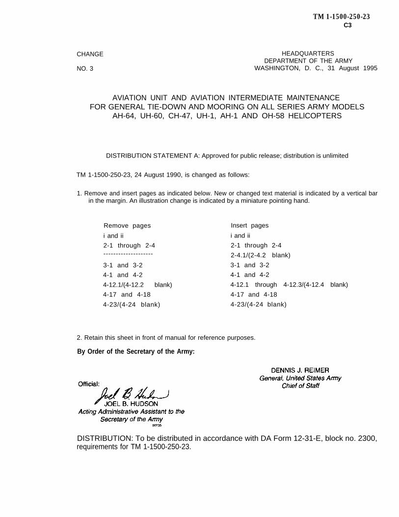
TM 1-1500-250-23C3
CHANGE HEADQUARTERSDEPARTMENT OF THE ARMY
NO. 3 WASHINGTON, D. C., 31 August 1995
AVIATION UNIT AND AVIATION INTERMEDIATE MAINTENANCEFOR GENERAL TIE-DOWN AND MOORING ON ALL SERIES ARMY MODELS
AH-64, UH-60, CH-47, UH-1, AH-1 AND OH-58 HELlCOPTERS
DISTRIBUTION STATEMENT A: Approved for public release; distribution is unlimited
TM 1-1500-250-23, 24 August 1990, is changed as follows:
1. Remove and insert pages as indicated below. New or changed text material is indicated by a vertical barin the margin. An illustration change is indicated by a miniature pointing hand.
Remove pages
i and ii
2-1 through 2-4--------------------
3-1 and 3-2
4-1 and 4-2
4-12.1/(4-12.2 blank)
4-17 and 4-18
4-23/(4-24 blank)
Insert pages
i and ii
2-1 through 2-4
2-4.1/(2-4.2 blank)
3-1 and 3-2
4-1 and 4-2
4-12.1 through 4-12.3/(4-12.4 blank)
4-17 and 4-18
4-23/(4-24 blank)
2. Retain this sheet in front of manual for reference purposes.
By Order of the Secretary of the Army:
DISTRIBUTION: To be distributed in accordance with DA Form 12-31-E, block no. 2300,requirements for TM 1-1500-250-23.


CHANGE
NO. 2
TM 1-1500-250-23C 2
HEADQUARTERSDEPARTMENT OF THE ARMY
WASHINGTON, D.C., 31 August 1993
AVIATION UNIT AND AVIATION INTERMEDIATE MAINTENANCE
FOR GENERAL TIE-DOWN AND MOORING ON ALL SERIES
ARMY MODELS AH-64 UH-60 CH-47 UH-1 AH-1 OH-58 HELICOPTERS
DISTRIBUTION STATEMENT A: Approved for public release; distribution is unlimited.
TM 1–1500-250-23, 24 August 1990, is changed as follows:
1. Remove and insert pages as indicated below. New or changed text material isindicated by a vertical bar in the margin. An illustration change is indi-cated by a miniature pointing hand.
Remove pages Insert pages
i and ii i and ii1-1 and 1-2 1-1 and 1-24-1 through 4-4 4-1 through 4-44-9 and 4-10 4-9 and 4-10----—-------- 4-12.1/(4-12.2 blank)
2. Retain this sheet in front of manual for reference purposes.
By Order of the Secretary of the Army:
Official:
MILTON H. HAMILTONAdministrative Assistant to the
Secretary of the Army0 5 2 8 2
GORDON R. SULLIVANGeneraI, United States Army
Chief of Staff
DISTRIBUTION:To be distributed in accordance with DA Form 12-31-E, block no. 2300, require-
ments for TM 1–1500-250-23.


CHANGE
NO. 1
AVIATION UNIT
FOR GENERAL
ARMY MODELS AH-64
TM 1-1500-250-23C 1
HEADQUARTERSDEPARTMENT OF THE ARMY
WASHINGTON, D.C., 30 September 1992
AND AVIATION INTERMEDIATE MAINTENANCE
TIE-DOWN AND MOORING ON ALL SERIES
UH-60 CH-47 UH-1 AH-1 OH-58 HELICOPTERS
TM 1-1500-250-23, 24 August 1990, is changed as follows:
1. Remove and insert pages as indicated below. New or changed text materialis indicated by a vertical bar in the margin. An illustration change is indicatedby a miniature pointing hand.
Remove pages Insert pages
2-1 and 2-2 2-1 through 2-43-1 and 3-2 3-1 and 3-23-5 and 3-6 3-5 and 3-64-17 and 4-18 4-17 and 4-18
2. Retain this sheet in front of manual for reference purposes.
By Order of the Secretary of the Army:
Official:
GORDON R. SULLIVANGeneral, United States Army
Chief of Staff
MILTON H. HAMILTONAdministrative Assistant to the
Secretary of the Army02658
DISTRIBUTION:To be distributed in accordance with DA Form 12–31-E, block no. 2300, require-
ments for TM 55-1500-250-23.
DISTRIBUTION STATEMENT A: Approved for public release; distribution is unlimited.


TM 1-1500-250-23
LIST OF EFFECTIVE PAGES
Insert latest changed pages; dispose of superseded pages in accordance with regulations.NOTE: On a changed page, the portion of the text affected by the latest change is indicated by a vertical line, orother change symbol, in the outer margin of the page. Changes to illustrations are indicated by miniature pointinghands. Changes to wiring diagrams are indicated by shaded areas.
Dates of issue for original and changed pages are:
Original . . . . . . . . . . . . . . . . . . . . . . . . 24 August 1990Change 1 . . . . . . . . . . . . . . . . . . 30 September 1992Change 2 . . . . . . . . . . . . . . . . . . . . . . 31 August 1993
Change 3 . . . . . . . . . . . . . . . . . . . . . . 31 August 1995Change 4 . . . . . . . . . . . . . . . . . . . . . . . . 31 May 1999Change 5 . . . . . . . . . . . . . . . . . . . . . . . . 24 April 2009
TOTAL NUMBER OF PAGES IN THIS PUBLICATION IS 63, CONSISTING OF THE FOLLOWING:
Page No. *Change No. Page No. *Change No.
Cover . . . . . . . . . . . . . . . . . . . . . . . . . . . . . . . . . . . . 5A . . . . . . . . . . . . . . . . . . . . . . . . . . . . . . . . . . . . . . . . . 5B Blank . . . . . . . . . . . . . . . . . . . . . . . . . . . . . . . . . . . 5i . . . . . . . . . . . . . . . . . . . . . . . . . . . . . . . . . . . . . . . . . . 5ii . . . . . . . . . . . . . . . . . . . . . . . . . . . . . . . . . . . . . . . . . 5iii . . . . . . . . . . . . . . . . . . . . . . . . . . . . . . . . . . . . . . . . . 51-1 . . . . . . . . . . . . . . . . . . . . . . . . . . . . . . . . . . . . . . . 51-2 . . . . . . . . . . . . . . . . . . . . . . . . . . . . . . . . . . . . . . . 52-1 . . . . . . . . . . . . . . . . . . . . . . . . . . . . . . . . . . . . . . . 52-2 . . . . . . . . . . . . . . . . . . . . . . . . . . . . . . . . . . . . . . . 52-3 . . . . . . . . . . . . . . . . . . . . . . . . . . . . . . . . . . . . . . . 52-4 . . . . . . . . . . . . . . . . . . . . . . . . . . . . . . . . . . . . . . . 52-4.1 . . . . . . . . . . . . . . . . . . . . . . . . . . . . . . . . . . . . . 32-4.2 Blank . . . . . . . . . . . . . . . . . . . . . . . . . . . . . . . . 02-5 . . . . . . . . . . . . . . . . . . . . . . . . . . . . . . . . . . . . . . . 02-6 . . . . . . . . . . . . . . . . . . . . . . . . . . . . . . . . . . . . . . . 03-1 . . . . . . . . . . . . . . . . . . . . . . . . . . . . . . . . . . . . . . . 53-2 . . . . . . . . . . . . . . . . . . . . . . . . . . . . . . . . . . . . . . . 03-3 . . . . . . . . . . . . . . . . . . . . . . . . . . . . . . . . . . . . . . . 53-4 . . . . . . . . . . . . . . . . . . . . . . . . . . . . . . . . . . . . . . . 43-5 . . . . . . . . . . . . . . . . . . . . . . . . . . . . . . . . . . . . . . . 53-6 . . . . . . . . . . . . . . . . . . . . . . . . . . . . . . . . . . . . . . . 53-7 . . . . . . . . . . . . . . . . . . . . . . . . . . . . . . . . . . . . . . . 53-8 Blank . . . . . . . . . . . . . . . . . . . . . . . . . . . . . . . . . 04-1 . . . . . . . . . . . . . . . . . . . . . . . . . . . . . . . . . . . . . . . 54-2 . . . . . . . . . . . . . . . . . . . . . . . . . . . . . . . . . . . . . . . 54-3 . . . . . . . . . . . . . . . . . . . . . . . . . . . . . . . . . . . . . . . 5
4-4 . . . . . . . . . . . . . . . . . . . . . . . . . . . . . . . . . . . . . . . 54-5 . . . . . . . . . . . . . . . . . . . . . . . . . . . . . . . . . . . . . . . 04-6 . . . . . . . . . . . . . . . . . . . . . . . . . . . . . . . . . . . . . . . 04-7 . . . . . . . . . . . . . . . . . . . . . . . . . . . . . . . . . . . . . . . 04-8 . . . . . . . . . . . . . . . . . . . . . . . . . . . . . . . . . . . . . . . 04-9 . . . . . . . . . . . . . . . . . . . . . . . . . . . . . . . . . . . . . . . 04-10 . . . . . . . . . . . . . . . . . . . . . . . . . . . . . . . . . . . . . . 54-11 . . . . . . . . . . . . . . . . . . . . . . . . . . . . . . . . . . . . . . 04-12 . . . . . . . . . . . . . . . . . . . . . . . . . . . . . . . . . . . . . . 04-12.1 . . . . . . . . . . . . . . . . . . . . . . . . . . . . . . . . . . . . 34-12.2 . . . . . . . . . . . . . . . . . . . . . . . . . . . . . . . . . . . . 34-12.3 . . . . . . . . . . . . . . . . . . . . . . . . . . . . . . . . . . . . 34-12.4 Blank . . . . . . . . . . . . . . . . . . . . . . . . . . . . . . 34-13 . . . . . . . . . . . . . . . . . . . . . . . . . . . . . . . . . . . . . . 54-14 . . . . . . . . . . . . . . . . . . . . . . . . . . . . . . . . . . . . . . 04-15 . . . . . . . . . . . . . . . . . . . . . . . . . . . . . . . . . . . . . . 04-16 . . . . . . . . . . . . . . . . . . . . . . . . . . . . . . . . . . . . . . 54-17 . . . . . . . . . . . . . . . . . . . . . . . . . . . . . . . . . . . . . . 54-18 . . . . . . . . . . . . . . . . . . . . . . . . . . . . . . . . . . . . . . 54-19 . . . . . . . . . . . . . . . . . . . . . . . . . . . . . . . . . . . . . . 04-20 . . . . . . . . . . . . . . . . . . . . . . . . . . . . . . . . . . . . . . 04-21 . . . . . . . . . . . . . . . . . . . . . . . . . . . . . . . . . . . . . . 54-22 . . . . . . . . . . . . . . . . . . . . . . . . . . . . . . . . . . . . . . 04-23 . . . . . . . . . . . . . . . . . . . . . . . . . . . . . . . . . . . . . . 54-24 Blank . . . . . . . . . . . . . . . . . . . . . . . . . . . . . . . . 5A-1 . . . . . . . . . . . . . . . . . . . . . . . . . . . . . . . . . . . . . . . 5A-2 Blank . . . . . . . . . . . . . . . . . . . . . . . . . . . . . . . . . 0
*Zero in this column indicates an original page.Change 5 A/(B Blank)


TM 1-1500-250-23
TECHNICAL MANUAL HEADQUARTERSDEPARTMENT OF THE ARMY
No. 1-1500-250-23 WASHINGTON, D.C., 24 August 1990
AVIATION UNIT AND AVIATIONINTERMEDIATE MAINTENANCE
FORGENERAL TIE-DOWN
AND MOORING ON ALL SERIESARMY MODELS
AH-64UH-60
CH/MH-47UH-1
OH-58HELICOPTERS
REPORTING ERRORS AND RECOMMENDING IMPROVEMENTSYou can improve this manual. If you nd mistakes or if you know of a way to improve theseprocedures, please let us know. Mail your letter or DA Form 2028 (Recommended Changesto Publications and Blank Forms) located in the back of this manual, directly to: Commander,U.S. Army Aviation and Missile Command, ATTN: AMSAM-MMC-MA-NP, Redstone Arsenal, AL35898-5000. A reply will be furnished to you. You may also provide DA Form 2028 information toAMCOM via email, fax, or the World Wide Web. Our fax number is: DSN 788-6546 or Commercial256 842-6546. Our email address is: [email protected]. Instructions for sending anelectronic 2028 may be found at the back of this manual immediately preceding the hard copy2028. For the World Wide Web use: https://amcom2028.redstone.army.mil.
OZONE DEPLETING CHEMICALS INFORMATIONThis document has been reviewed for the presence of Class I Ozone Depleting Chemicals. As of change 4 dated 31 May1999. All references to Class I Ozone Depleting Chemicals have been removed from this document by substitution withnon-ozone depleting chemicals.
DISTRIBUTION STATEMENT A: Approved for public release; distribution is unlimited.
TABLE OF CONTENTSPage
CHAPTER 1 INTRODUCTION . . . . . . . . . . . . . . . . . . . . . . . . . . . . . . . . . . . . . . . . . . . . . . . . . . . . . . . . . . . . . . . 1-1Section I GENERAL . . . . . . . . . . . . . . . . . . . . . . . . . . . . . . . . . . . . . . . . . . . . . . . . . . . . . . . . . . . . . . . . . . . 1-1
1-1 Scope. . . . . . . . . . . . . . . . . . . . . . . . . . . . . . . . . . . . . . . . . . . . . . . . . . . . . . . . . . . . . . . . . . . . . 1-11-2 Maintenance Forms and Records. . . . . . . . . . . . . . . . . . . . . . . . . . . . . . . . . . . . . . . . . . . . 1-11-3 Reporting Errors and Recommending Improvements. . . . . . . . . . . . . . . . . . . . . . . . . . . 1-11-4 Conicts Between TMs. . . . . . . . . . . . . . . . . . . . . . . . . . . . . . . . . . . . . . . . . . . . . . . . . . . . . . 1-1
Section II DESCRIPTION AND APPLICATION . . . . . . . . . . . . . . . . . . . . . . . . . . . . . . . . . . . . . . . . . . . 1-21-5 Necessity of TM. . . . . . . . . . . . . . . . . . . . . . . . . . . . . . . . . . . . . . . . . . . . . . . . . . . . . . . . . . . . 1-21-6 Army Policy. . . . . . . . . . . . . . . . . . . . . . . . . . . . . . . . . . . . . . . . . . . . . . . . . . . . . . . . . . . . . . . . 1-2
CHAPTER 2 HARDWARE AND AIRCRAFT REQUIREMENTS . . . . . . . . . . . . . . . . . . . . . . . . . . . . . . . . . . 2-12-1 Grid Pattern Layout and Mooring Point Strength. . . . . . . . . . . . . . . . . . . . . . . . . . . . . . . 2-12-2 Mooring Pad Marking. . . . . . . . . . . . . . . . . . . . . . . . . . . . . . . . . . . . . . . . . . . . . . . . . . . . . . . 2-12-3 General Tools and Equipment. . . . . . . . . . . . . . . . . . . . . . . . . . . . . . . . . . . . . . . . . . . . . . . . 2-1
Change 5 i

TM 1-1500-250-23
TABLE OF CONTENTS (Cont)Page
CHAPTER 3 TIE-DOWN PROCEDURES . . . . . . . . . . . . . . . . . . . . . . . . . . . . . . . . . . . . . . . . . . . . . . . . . . . . . . 3-13-1 General Tie-Down Procedures. . . . . . . . . . . . . . . . . . . . . . . . . . . . . . . . . . . . . . . . . . . . . . . 3-13-2 Specic Aircraft Tie-Down. . . . . . . . . . . . . . . . . . . . . . . . . . . . . . . . . . . . . . . . . . . . . . . . . . . 3-1
CHAPTER 4 MOORING PROCEDURES . . . . . . . . . . . . . . . . . . . . . . . . . . . . . . . . . . . . . . . . . . . . . . . . . . . . . . 4-14-1 General Mooring. . . . . . . . . . . . . . . . . . . . . . . . . . . . . . . . . . . . . . . . . . . . . . . . . . . . . . . . . . . . 4-14-2 Specic Aircraft Mooring Procedures. . . . . . . . . . . . . . . . . . . . . . . . . . . . . . . . . . . . . . . . . 4-14-3 Mooring on Non-paved Surfaces. . . . . . . . . . . . . . . . . . . . . . . . . . . . . . . . . . . . . . . . . . . . . 4-18
APPENDIX A References . . . . . . . . . . . . . . . . . . . . . . . . . . . . . . . . . . . . . . . . . . . . . . . . . . . . . . . . . . . . . . . . . . . . . A-1
LIST OF ILLUSTRATIONS
Figure Title Page2-1 Mooring Pad Hardpoint Spacing . . . . . . . . . . . . . . . . . . . . . . . . . . . . . . . . . . . . . . . . . . . . . . . . . . . . . . . . . . 2-4.12-2 Mooring Pad Maximum Load Conditions . . . . . . . . . . . . . . . . . . . . . . . . . . . . . . . . . . . . . . . . . . . . . . . . . . . 2-52-3 MB-1 Chain Adjuster Assembly . . . . . . . . . . . . . . . . . . . . . . . . . . . . . . . . . . . . . . . . . . . . . . . . . . . . . . . . . . . 2-63-1 OH-58D Tie-Down Conguration . . . . . . . . . . . . . . . . . . . . . . . . . . . . . . . . . . . . . . . . . . . . . . . . . . . . . . . . . . 3-23-2 OH-58A/C Tie-Down Conguration . . . . . . . . . . . . . . . . . . . . . . . . . . . . . . . . . . . . . . . . . . . . . . . . . . . . . . . . 3-23-3 AH-64 Tie-Down Conguration . . . . . . . . . . . . . . . . . . . . . . . . . . . . . . . . . . . . . . . . . . . . . . . . . . . . . . . . . . . 3-3
3-3a Deleted . . . . . . . . . . . . . . . . . . . . . . . . . . . . . . . . . . . . . . . . . . . . . . . . . . . . . . . . . . . . . . . . . . . . . . . . . . . . . . . . . 3-43-4 UH-60 Tie-Down Conguration . . . . . . . . . . . . . . . . . . . . . . . . . . . . . . . . . . . . . . . . . . . . . . . . . . . . . . . . . . . 3-53-5 Deleted . . . . . . . . . . . . . . . . . . . . . . . . . . . . . . . . . . . . . . . . . . . . . . . . . . . . . . . . . . . . . . . . . . . . . . . . . . . . . . . . . 3-53-6 UH-1 Tie-Down Conguration . . . . . . . . . . . . . . . . . . . . . . . . . . . . . . . . . . . . . . . . . . . . . . . . . . . . . . . . . . . . 3-63-7 CH/MH-47 Tie-Down Conguration . . . . . . . . . . . . . . . . . . . . . . . . . . . . . . . . . . . . . . . . . . . . . . . . . . . . . . . 3-63-8 CH/MH-47 Tie-Down Conguration (Optional) . . . . . . . . . . . . . . . . . . . . . . . . . . . . . . . . . . . . . . . . . . . . . . 3-74-1 Mooring Hardware Installation Assembly Details - Conguration 1 . . . . . . . . . . . . . . . . . . . . . . . . . . . 4-54-2 Mooring Hardware Installation Assembly Details - Conguration 2 . . . . . . . . . . . . . . . . . . . . . . . . . . . 4-54-3 Mooring Hardware Details in Conguration 1 (Figure 4-1) . . . . . . . . . . . . . . . . . . . . . . . . . . . . . . . . . . . 4-64-4 Link, Chain Detachable . . . . . . . . . . . . . . . . . . . . . . . . . . . . . . . . . . . . . . . . . . . . . . . . . . . . . . . . . . . . . . . . . . 4-74-5 Link, Chain, Detachable Installation . . . . . . . . . . . . . . . . . . . . . . . . . . . . . . . . . . . . . . . . . . . . . . . . . . . . . . . 4-84-6 AH-64 Mooring Conguration . . . . . . . . . . . . . . . . . . . . . . . . . . . . . . . . . . . . . . . . . . . . . . . . . . . . . . . . . . . . . 4-94-7 CH/MH47 Mooring Conguration . . . . . . . . . . . . . . . . . . . . . . . . . . . . . . . . . . . . . . . . . . . . . . . . . . . . . . . . . 4-104-8 UH-60 Mooring Conguration . . . . . . . . . . . . . . . . . . . . . . . . . . . . . . . . . . . . . . . . . . . . . . . . . . . . . . . . . . . . . 4-11
4-8a UH-60 Mooring Conguration (When external fuel tanks are installed) . . . . . . . . . . . . . . . . . . . . . . . . 4-124-8b EH-60 Mooring Conguration . . . . . . . . . . . . . . . . . . . . . . . . . . . . . . . . . . . . . . . . . . . . . . . . . . . . . . . . . . . . . 4-12.14-8c UH-60 Mooring Conguration Alternate # 1 . . . . . . . . . . . . . . . . . . . . . . . . . . . . . . . . . . . . . . . . . . . . . . . . 4-12.24-8d UH-60 Mooring Conguration Alternate # 2 . . . . . . . . . . . . . . . . . . . . . . . . . . . . . . . . . . . . . . . . . . . . . . . . 4-12.34-9 Deleted . . . . . . . . . . . . . . . . . . . . . . . . . . . . . . . . . . . . . . . . . . . . . . . . . . . . . . . . . . . . . . . . . . . . . . . . . . . . . . . . . 4-13
4-10 UH-1 Mooring Conguration . . . . . . . . . . . . . . . . . . . . . . . . . . . . . . . . . . . . . . . . . . . . . . . . . . . . . . . . . . . . . . 4-144-11 OH-58A&C Mooring Conguration . . . . . . . . . . . . . . . . . . . . . . . . . . . . . . . . . . . . . . . . . . . . . . . . . . . . . . . . 4-154-12 OH-58D Mooring Conguration . . . . . . . . . . . . . . . . . . . . . . . . . . . . . . . . . . . . . . . . . . . . . . . . . . . . . . . . . . . 4-154-13 Mooring Hardware For OH-58A/C&D . . . . . . . . . . . . . . . . . . . . . . . . . . . . . . . . . . . . . . . . . . . . . . . . . . . . . . 4-164-14 Bushing Detail for OH-58A/C and D . . . . . . . . . . . . . . . . . . . . . . . . . . . . . . . . . . . . . . . . . . . . . . . . . . . . . . . 4-174-15 Pin, Quick Release For OH-58A/C and D . . . . . . . . . . . . . . . . . . . . . . . . . . . . . . . . . . . . . . . . . . . . . . . . . . 4-174-16 Ground Anchor Assembly (For Mooring on Nonpaved Surfaces) . . . . . . . . . . . . . . . . . . . . . . . . . . . . . 4-204-17 Ground Anchor with Wire Rope . . . . . . . . . . . . . . . . . . . . . . . . . . . . . . . . . . . . . . . . . . . . . . . . . . . . . . . . . . . 4-214-18 Driving Rod . . . . . . . . . . . . . . . . . . . . . . . . . . . . . . . . . . . . . . . . . . . . . . . . . . . . . . . . . . . . . . . . . . . . . . . . . . . . . 4-214-19 Drive Head . . . . . . . . . . . . . . . . . . . . . . . . . . . . . . . . . . . . . . . . . . . . . . . . . . . . . . . . . . . . . . . . . . . . . . . . . . . . . 4-214-20 Holding Handle . . . . . . . . . . . . . . . . . . . . . . . . . . . . . . . . . . . . . . . . . . . . . . . . . . . . . . . . . . . . . . . . . . . . . . . . . 4-21
ii Change 5

TM 1-1500-250-23
LIST OF ILLUSTRATIONS (Cont)Figure Title Page
4-21 Installation of the Ground Anchor Assembly . . . . . . . . . . . . . . . . . . . . . . . . . . . . . . . . . . . . . . . . . . . . . . . . 4-224-22 Polyester Rope and Webbing Binder . . . . . . . . . . . . . . . . . . . . . . . . . . . . . . . . . . . . . . . . . . . . . . . . . . . . . . 4-23
Change 5 iii/(iv Blank)


TM 1-1500-250-23
CHAPTER 1INTRODUCTION
SECTION I GENERAL
1-1. SCOPE.
This manual supplements, claries, standardizes the tie-down and mooring procedures in the -23 Technical Man-uals for all series AH-64, UH-60, CH/MH-47, UH-1, andOH-58 helicopters to the maximum extent practical.
1-2. MAINTENANCE FORMS AND RECORDS.
The maintenance forms and records which are requiredby personnel who perform the maintenance functionsprescribed in this manual are listed in DA PAM 738-751.
1-3. REPORTING ERRORS AND RECOMMENDINGIMPROVEMENTS.
You can improve this manual. If you nd mistakes or ifyou know of a way to improve the procedures, pleaselet us know. Mail your letter or DA Form 2028 (Rec-ommended Changes to Publications and Blank Forms)located in the back of this manual, directly to: Com-mander, U.S. Army Aviation and Missile Command,ATTN: AMSAM-MMC-MA-NP, Redstone Arsenal, AL35898-5000. A reply will be furnished to you. You mayalso provide DA Form 2028 information to AMCOM via
e-mail, fax, or the World Wide Web. Our fax numberis: DSN 788-6546 or Commercial 256 842-6546. Oure-mail address is: [email protected]. Instruc-tions for sending an electronic 2028 may be found atthe back of this manual immediately preceding the hardcopy 2028. For the World Wide Web use: https://am-com2028.redstone.army.mil.
1-4. CONFLICTS BETWEEN TMS.
When a conict exists between this General TM and theaircraft specic -23 TMs, the Tie-Down and Mooring pro-cedures described in this General TM shall be followed.The following TMs will be affected by this General TM:
OH-58D TM 1-1520-248-23
OH-58A/C TM 55-1520-228-23
AH-64 TM 1-1520-238-23UH-60 TM 1-1520-237-23
UH-1 TM 55-1520-210-23
CH/MH-47 TM 1-1520-240-23
Change 5 1-1

TM 1-1500-250-23
SECTION II DESCRIPTION AND APPLICATION
1-5. NECESSITY OF TM.
This General TM became necessary because of the ap-parent ineffectiveness of past tie-down and mooring pro-cedures. In the spring of 1989 Army aircraft at Ft. Hoodand Ft. Polk experienced extensive and costly damageas a result of very high winds. In each instance, se-vere storm warnings had been issued and current pro-cedures were followed within available time and capa-bilities. Despite these measures serious damage to air-craft and losses to the Army in combat readiness andresources occurred.
1-6. ARMY POLICY. The following Department of theArmy policy has been established: when notied of thepotential for severe windstorms in excess of 50 knotsall Army aviation units will take the actions prescribed inthis General TM.
a. If unable to evacuate to a safe haven, air-craft will be placed in hangars in the follow-ing priority; OH-58D/C/A, AH-64A, UH-60A,AH-64D and UH-60L/Q, UH-IV/H, HH-60 andCH-47F/D/C. The priority for special opera-tions aircraft is: MH/AH-6, MH-60, MH-47 andOH-6. For helicopter with more than two mainrotor blades, if feasible, the blades will be re-moved or folded to maximize available hangarspace.
b. All aircraft remaining outside will be tied downand moored in accordance with appropriateprocedures described in this General TM.When feasible, units will face the aircraft intothe forecasted wind before mooring.
c. Aviation units will also take additional protec-tion measures to include use of all availableshelters and/or articial barriers such as revet-ments, berms, igloos, trucks, buses, tanks, ar-mored carriers, etc.
d. Army aircraft located in areas that experiencesevere windstorms will tie down blades aftereach ight and moor aircraft after the last ightof the day regardless of the weather forecast.If aircraft are not to be own they shall be lefttied down and moored.
e. Every installation with Army aviation units willhave secure mooring points for all assigned air-craft. Where points are not sufcient, installa-tion engineers will take immediate action to in-stall required mooring points.
f. All units with assigned aircraft will ensure tie-down/mooring hardware, particular to each air-craft, is in good repair.
g. The horizontal stabilator of the UH-60 andAH-64 aircraft are to be set in the neutral posi-tion (zero degrees).
NOTE
If unable to conform to the congurationsshown, contact AMCOM Engineering (DSN897-4905) or comm. 256-313-4905 for guid-ance.
1-2 Change 5

TM 1-1500-250-23
CHAPTER 2HARDWARE AND AIRCRAFT REQUIREMENTS
2-1. GRID PATTERN LAYOUT AND MOORINGPOINT STRENGTH. The grid pattern layout illustratingthe 17 to 20 foot on center mooring points is depictedin gure 2-1.
a. This pattern readily accommodates all the he-licopters in the army eet and should be usedas the standard for new mooring installations.
b. The strength of each mooring point should becapable of reacting to the design loads de-picted in gure 2-2.
2-2. MOORING PAD MARKING. Marking the moor-ing pad to properly position the aircraft is recommendedif the pad is to be used exclusively for one type of air-craft.
2-3. GENERAL TOOLS AND EQUIPMENT.
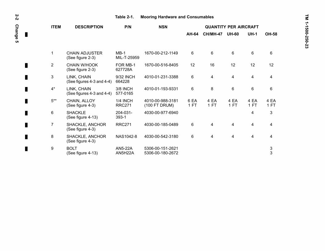
a. All aircraft will use polyester rope for rotor bladetie-down. Refer to table 2-1.
(1) Tie-down OH-58D as specied in the ap-propriate aircraft Technical Manual.
(2) Tie-down OH-58A/C as specied in theappropriate Technical Manual, except thattwo main rotor blade tie-down boots arerequired.
(3) Tie-down AH-64 as specied in the appro-priate Technical Manual. Ensure that theropes are strong enough to allow the mainrotor blades to be secured at the requiredlocations.
(4) Tie-down UH-60 as specied in the appro-priate Technical Manual.
(5) Deleted.
(6) Tie-down UH-1 as specied in the appro-priate Technical Manual, except that a for-ward main rotor blade tie-down strap is re-quired.
(7) Tie-down CH/MH-47 as specied in theappropriate Technical Manual.
b. Tie-down and Mooring Equipment. Refer totable 2-1.
(1) Acquisition and maintenance of all re-quired tie-down and mooring equipmentis the responsibility of the aviation units.
(2) The identied chain and chain adjustershall be used as the primary mooringequipment for all helicopters when parkedat their home installation and Army policy(per paragraph 1-6) requires mooring.Exceptions to the use of mooring chainsis only approved under special circum-stances where chain has proven to beundesirable such as the crossover moor-ing on the CH/MH-47D.
(3) Mooring chains and chain adjusters arenot considered yaway equipment. The10,000 pound capacity polyester mooringstrap with ratchet buckle, NSN 5340-01-233-3063, is the identied yaway whichmay be used when aircraft deployed awayfrom their home station require mooringand chains are not available. The CGU-1B, 5000 pound capacity nylon tie-downstrap, NSN 1670-00-725-1437, is only au-thorized when hard stand mooring pointsare not available and the eld mooring kitis used.
Change 5 2-1
TM1-1500-250-23
Table 2-1. Mooring Hardware and Consumables
ITEM DESCRIPTION P/N NSN QUANTITY PER AIRCRAFTAH-64 CH/MH-47 UH-60 UH-1 OH-58
1 CHAIN ADJUSTER(See gure 2-3)
MB-1MIL-T-25959
1670-00-212-1149 6 6 6 6 6
2 CHAIN W/HOOK(See gure 2-3)
FOR MB-1627728A
1670-00-516-8405 12 16 12 12 12
3 LINK, CHAIN(See gures 4-3 and 4-4)
9/32 INCH664228
4010-01-231-3388 6 4 4 4 4
4* LINK, CHAIN(See gures 4-3 and 4-4)
3/8 INCH577-0165
4010-01-193-9331 6 8 6 6 6
5** CHAIN, ALLOY(See gure 4-3)
1/4 INCHRRC271
4010-00-988-3181(100 FT DRUM)
6 EA1 FT
4 EA1 FT
4 EA1 FT
4 EA1 FT
4 EA1 FT
6 SHACKLE(See gure 4-13)
204-031-393-1
4030-00-977-6940 4 3
7 SHACKLE, ANCHOR(See gure 4-3)
RRC271 4030-00-185-0489 6 4 4 4 4
8 SHACKLE, ANCHOR(See gure 4-3)
NAS1042-8 4030-00-542-3180 6 4 4 4 4
9 BOLT(See gure 4-13)
AN5-22AAN5H22A
5306-00-151-26215306-00-180-2672
33
2-2C
hange5

TM1-1500-250-23
Table 2-1. Mooring Hardware and Consumables — Continued
ITEM DESCRIPTION P/N NSN QUANTITY PER AIRCRAFTAH-64 CH/MH-47 UH-60 UH-1 OH-58
10 BOLT, g 4-13 AN5-23AAN5H23A
5306-00-151-26205306-00-180-2673
33
11 WASHER, g 4-13 AN960PD516 5310-00-187-2399 6
12 NUT, g 4-13 MS21042L5 5310-00-807-1476 3
13*** BUSHING, g 4-14 3
14 PIN, QUICKRELEASE, g 4-15
MS17985-520
5315-00-702-3102 3
15 ROPE, 1/2 INCHPOLYESTER
MIL-R-24537 4020-01-028-3843(200 FT ROLL)
16 ROPE, 1/2 INCHPOLYESTER
MIL-R-24335 4020-00-765-3928(1000 FT ROLL)
17 ROPE, 1/2 INCHPOLYESTER
MIL-R-30500 4020-00-630-4873(1200 FT ROLL)
Change
52-3
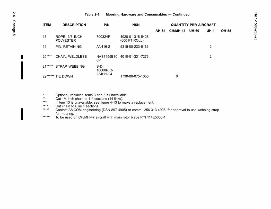
TM1-1500-250-23
Table 2-1. Mooring Hardware and Consumables — Continued
ITEM DESCRIPTION P/N NSN QUANTITY PER AIRCRAFTAH-64 CH/MH-47 UH-60 UH-1 OH-58
18 ROPE, 3/8 INCHPOLYESTER
700324R 4020-01-318-5428(600 FT ROLL)
19 PIN, RETAINING AN416-2 5315-00-223-6112 2
20**** CHAIN, WELDLESS NAS1455B306P
4010-01-331-7273 2
21***** STRAP, WEBBING B-D-10000R/O-234HH-24
22****** TIE DOWN 1730-00-075-1055 6
* Optional, replaces items 3 and 5 if unavailable.** Cut 1/4 inch chain to 1 ft sections (14 links).*** If item 13 is unavailable, see gure 4-13 to make a replacement.**** Cut chain to 6 inch sections.***** Contact AMCOM engineering (DSN 897-4905) or comm. 256-313-4905, for approval to use webbing strap
for mooring.****** To be used on CH/MH-47 aircraft with main rotor blade P/N 114E5060-1.
2-4C
hange5

TM 1-1500-250-23
Figure 2-1. Mooring Pad Hardpoint SpacingChange 3 2-4.1/(2-4.2 blank)


TM 1-1500-250-23
THE LOADS SHOWN ARE THE MAXIMUMS CALCULATEDTO MOOR ARMY HELlCOPTERS IN 100 KNOT WINDS,IT IS RECOMMENDED THAT THE MOORING DEVICE BECAPABLE OF WITHSTANDING THE MAXIMUM LOADS SHOWN.
Figure 2-2. Mooring Pad Maximum Load Conditions
2-5

TM 1-1500-250-23
2-6
MB-1 CHAIN ADJUSTER ASSEMBLY
EASY LOADING QUICK RELEASE AT 10,000 LB. LOAD
POSITIVE LOCK ADJUSTMENT TO ANY CHAIN LINK -
ULTIMATE LOAD — 14,100 LBS. PLUS 3-1/2” OF SCREW ADJUSTMENT.
MEETS REQ. OF SPECIFICATION - WEIGHT — 3-1/2 LBS. MAXIMUM
MIL-T-25959 TYPE MB-1 HOOK — THROAT /8"
TO BE USED WITH TYPE 1 CHAIN STEEL PARTS CADMIUM PLATED
ASSEMBLY PER MIL-C-6458
Figure 2-3. MB-1 Chain Adjuster Assembly

TM 1-1500-250-23
CHAPTER 3TIE-DOWN PROCEDURES
3-1. GENERAL TIE-DOWN PROCEDURES. Linetension tie-down lines from all main rotor blades shallbe taut, but care must be taken to ensure excessivedeection of blades below the static jacking, droopposition, as stated in the specic aircraft -23 TMs, is notexceeded.
3-2. SPECIFIC AIRCRAFT TIE-DOWN.
a. OH-58D tie-down blades as specied in the-23 Technical Manual and as shown in gure3-1 of this general TM. Use the polyester ropereferenced in this manual.
b. OH-58A/C tie-down blades as specied in the-23 Technical Manual and as shown in gure3-2 of this general TM. Securely tie the strapsof the boot to the polyester rope near the boot.Ensure the ropes are long enough to crossand tie in the position illustrated. The forwardblade shall be tied down using the same bootstrap/rope arrangement device. The ropesshall be tied to the forward eyebolts of thelanding skid. The ropes, as an option, can besecured to the forward eyebolts of the landingskid by either tying or using a self closing hookthat is the same strength or as strong as thepolyester rope, to anchor tie-down rope to theskid rings.
NOTEOptional tie-down procedure for the OH-58A/Cis applicable also to the UH-1 aircraft.
c. AH-64 tie-down blades as specied in the -23Technical Manual and as shown in gure 3-3of this general TM. Ensure that the main ro-tor blade tie-down boot is in good repair andthat the two nylon end straps are securely at-tached (refer to gure 3-3, blow-up). Replacethe 3/8 inch nylon rope with polyester rope.3/8 inch diameter standard polyester rope canbe substituted directly. 1/2 inch diameter stan-dard polyester rope can be secured to the bootby forming a small loop with the existing ny-lon rope and tying the polyester rope to theloop. Ensure that the rope is long enough toreach the proper aircraft hard points. The rightaft boot must have an additional length of ropeto secure to the aft outboard wing pylons way
brace or to secure to the aft wing store sus-pension lug. The other rope attaches to the aftjacking tting at FS450. This conguration willprevent the boot from slipping off.
d. UH-60 tie-down blades as specied in the -23Technical Manual and as shown in gure 3-4 ofthis general TM. To prevent damage from thelock release cable in strong winds, wrap thecable several times around the tie-down ropeand slip the end loop through one of the cablewraps.
e. Deleted.
f. UH-1 tie-down aft blades as specied in the-23 Technical Manual and as shown in gure3-6 of this general TM. Engage hook of mainrotor tie-down in hole of tting on each rotorblade and position blade above tailboom. Pullon tie-down to remove spanwise slack fromthe rotor system and secure rotor blade bywrapping the tie-down rope rmly around tail-boom as shown in gure 3-6. Tie forwardrope tie-down rope to tow rings, as shown ingure 3-6, on landing gear skid. Additionalsecurity of main rotor can be accomplishedby inserting an AN416-2 safety retaining pinthrough a 0.060 inch hole drilled through thehook of the main rotor tie-down. The hole isdrilled perpendicular to the plane of the handle,0.25 inch from the insertion end of the hook.Secure the safety retaining pin to the hookhandle with a 6-inch piece of NAS1455B30-6Pchain and safety wire. Insert the safety re-taining pin through the hook after inserting thehook through the rotor blade tting. In the naltie-down position, the blades must not exceed6 inches of additional droop from having beenpulled down. This applies to both metal andcomposite blades.
g. CH/MH-47 tie-down blades as specied in -23Technical Manual and gures 3-7 or 3-8 ofthis general TM. Use gure 3-7 for normal air-craft tie-down. As an option, the CH/MH-47blades may be secured to the mooring padhard points, as shown in gure 3-8, providedthe aircraft is secured using the mooring pro-cedures in this TM.
Change 5 3-1

TM 1-1500-250-23
Figure 3-1. OH-58D Tie-Down Conguration
Figure 3-2. OH-58A/C Tie-Down Conguration
3-2

TM 1-1500-250-23
Figure 3-3. AH-64 Tie-Down Conguration
Change 5 3-3

TM 1-1500-250-23
Figure 3-3a. Deleted
3-4 Change 4

TM 1-1500-250-23
Figure 3-4. UH-60 Tie-Down Conguration
Figure 3-5. Deleted
Change 5 3-5

TM 1-1500-250-23
Figure 3-6. UH-1 Tie-Down Conguration
Figure 3-7. CH/MH-47 Tie-Down Conguration
3-6 Change 5

TM 1-1500-250-23
Figure 3-8. CH/MH-47 Tie-Down Conguration (Optional)
Change 5 3-7/(3-8 Blank)

TM 1-1500-250-23
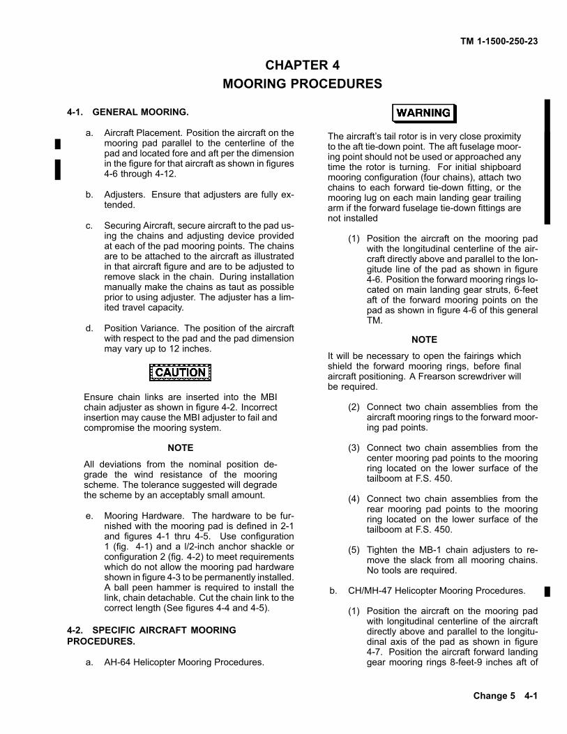
CHAPTER 4MOORING PROCEDURES
4-1. GENERAL MOORING.
a. Aircraft Placement. Position the aircraft on themooring pad parallel to the centerline of thepad and located fore and aft per the dimensionin the gure for that aircraft as shown in gures4-6 through 4-12.
b. Adjusters. Ensure that adjusters are fully ex-tended.
c. Securing Aircraft, secure aircraft to the pad us-ing the chains and adjusting device providedat each of the pad mooring points. The chainsare to be attached to the aircraft as illustratedin that aircraft gure and are to be adjusted toremove slack in the chain. During installationmanually make the chains as taut as possibleprior to using adjuster. The adjuster has a lim-ited travel capacity.
d. Position Variance. The position of the aircraftwith respect to the pad and the pad dimensionmay vary up to 12 inches.
Ensure chain links are inserted into the MBIchain adjuster as shown in gure 4-2. Incorrectinsertion may cause the MBI adjuster to fail andcompromise the mooring system.
NOTE
All deviations from the nominal position de-grade the wind resistance of the mooringscheme. The tolerance suggested will degradethe scheme by an acceptably small amount.
e. Mooring Hardware. The hardware to be fur-nished with the mooring pad is dened in 2-1and gures 4-1 thru 4-5. Use conguration1 (g. 4-1) and a l/2-inch anchor shackle orconguration 2 (g. 4-2) to meet requirementswhich do not allow the mooring pad hardwareshown in gure 4-3 to be permanently installed.A ball peen hammer is required to install thelink, chain detachable. Cut the chain link to thecorrect length (See gures 4-4 and 4-5).
4-2. SPECIFIC AIRCRAFT MOORINGPROCEDURES.
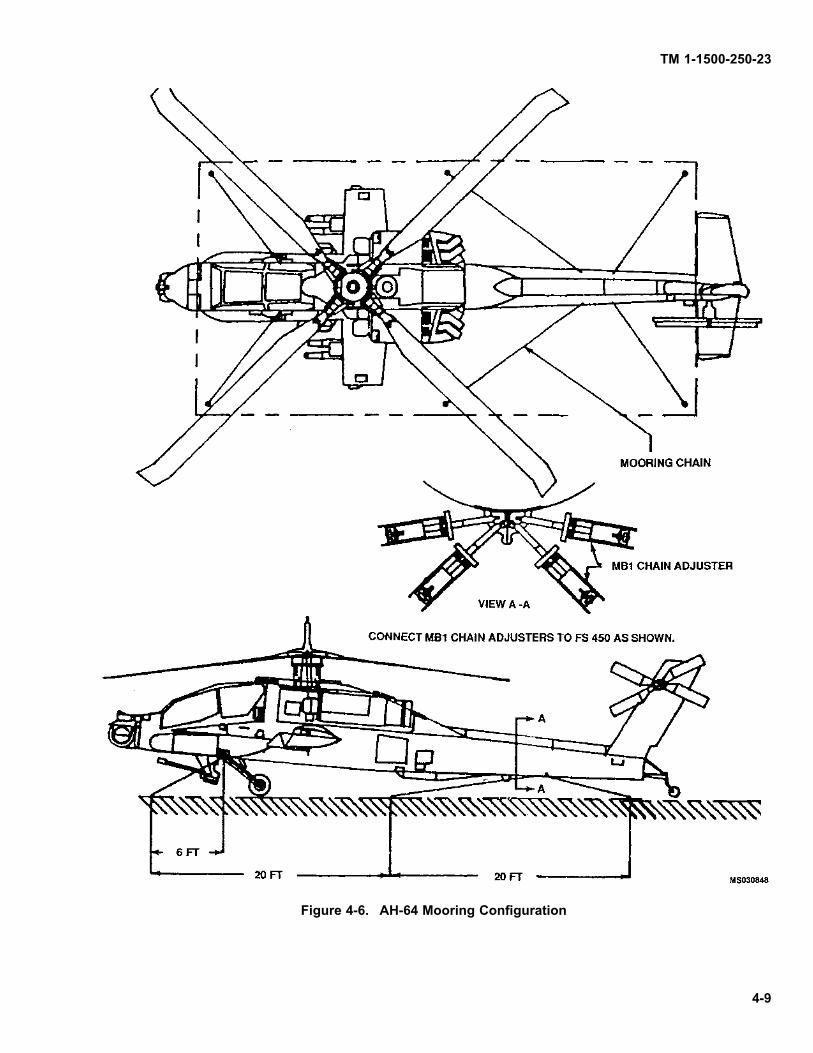
a. AH-64 Helicopter Mooring Procedures.
The aircraft’s tail rotor is in very close proximityto the aft tie-down point. The aft fuselage moor-ing point should not be used or approached anytime the rotor is turning. For initial shipboardmooring conguration (four chains), attach twochains to each forward tie-down tting, or themooring lug on each main landing gear trailingarm if the forward fuselage tie-down ttings arenot installed
(1) Position the aircraft on the mooring padwith the longitudinal centerline of the air-craft directly above and parallel to the lon-gitude line of the pad as shown in gure4-6. Position the forward mooring rings lo-cated on main landing gear struts, 6-feetaft of the forward mooring points on thepad as shown in gure 4-6 of this generalTM.
NOTE
It will be necessary to open the fairings whichshield the forward mooring rings, before nalaircraft positioning. A Frearson screwdriver willbe required.
(2) Connect two chain assemblies from theaircraft mooring rings to the forward moor-ing pad points.
(3) Connect two chain assemblies from thecenter mooring pad points to the mooringring located on the lower surface of thetailboom at F.S. 450.
(4) Connect two chain assemblies from therear mooring pad points to the mooringring located on the lower surface of thetailboom at F.S. 450.
(5) Tighten the MB-1 chain adjusters to re-move the slack from all mooring chains.No tools are required.
b. CH/MH-47 Helicopter Mooring Procedures.
(1) Position the aircraft on the mooring padwith longitudinal centerline of the aircraftdirectly above and parallel to the longitu-dinal axis of the pad as shown in gure4-7. Position the aircraft forward landinggear mooring rings 8-feet-9 inches aft of
Change 5 4-1

TM 1-1500-250-23
the forward mooring points on the pad asshown in gure 4-7 of this general TM.
(2) Connect two crossing chain assembliesfrom the forward landing gear mooringrings diagonally to the forward mooringpad points.
(3) Connect two side chain assemblies fromthe forward landing gear mooring rings tothe forward mooring pad points.
(4) Connect two crossing chain assembliesdiagonally from the aft aircraft landinggear mooring rings to the rear mooringpad points.
(5) Connect two side chain assemblies fromthe aft aircraft landing gear mooring ringsto the rear mooring pad points.
(6) Tighten the MB-1 adjusters to remove theslack from all mooring chains. Not toolsare required.
c. UH-60 Helicopter Morning Procedures.
(1) Position the aircraft on the mooring padwith the longitudinal centerline of the air-craft directly above and parallel to the lon-gitudinal axis of the pad as shown in g-ures 4-8, 4-8a, 4-8b, 4-8c and 4-8d. Fig-ures 4-8, 4-8c and 4-8d are to be used foraircraft that do not have external tanks in-stalled Figure 4-8a is to be used when air-craft have external tanks installed. Figure4-8b is to be used for the EH-60 aircraft.
(2) For mooring of the UH-60 per gure 4-8:
(a) Position the aircraft front roomingrings directly in-line with the frontmooring pad points.
(b) Connect two chain assemblies fromthe forward aircraft mooring rings atF.S. 308 to the front rooming padpoints.
(c) Connect two chain assemblies fromthe front mooring pad points to the aftaircraft mooring rings at F.S.485.
(d) Connect two chain assemblies fromthe aft aircraft mooring rings to thecenter rooming pad points.
(e) Tighten the MB-1 chain adjusters toremove the slack from all mooringchains. No tools are required.
(3) For mooring the UH-60 per gure 4-8a:
(a) Position the aircraft cargo hook di-rectly in-line with the center mooringpad points.
(b) Connect two lateral chain assembliesfrom the aircraft cargo hook to thecenter mooring pad points (Ref. g-ure 4-8a, view A-A).
(c) Connect two chain assemblies fromthe center mooring pad points to theaft aircraft mooring rings at F.S.485.
(d) Connect two chain assemblies fromthe aft aircraft mooring rings to therear mooring pad points.
(e) Tighten the MB-1 chain adjusters toremove the slack from all mooringchains. No tools are required.
(4) For mooring the EH-60 per gure 4-8b:
(a) Position the aircraft front roomingrings directly in-line with the frontmooring pad points.
(b) Connect two chain assemblies fromthe forward aircraft mooring rings atF.S. 308 to the front mooring padpoints.
(c) Connect two chain assemblies fromthe center mooring pad points to theforward aircraft rooming rings at F.S.308.
(d) Connect two chain assemblies fromthe aft aircraft mooring rings at F.S.485 to the center mooring pad points.
(e) Tighten the MB-1 chain adjusters toremove the slack from all mooringchains. No tools are required.
(5) For alternate mooring of UH-60 per gure4-8c:
(a) Position the aircraft front mooringrings directly in-line with the centermooting pad points as shown in gure4-8c.
4-2 Change 5

TM 1-1500-250-23
(b) Connect two chain assemblies fromthe forward aircraft mooring rings atF.S. 308 to center mooring pad pointsas shown in gure 4-8c.
(c) Connect two chain assemblies fromthe center mooring pad points to theaft aircraft mooring rings at F.S.485 asshown in gure 4-8c.
(d) Connect two chain assemblies fromthe aft aircraft mooing rings at F.S.485 to the rear mooring pad points asshown in gure 4-8c.
(e) Tighten the MB-l chain adjusters toremove the slack from all mooringchains. No tools are required.
(6) For alternate mooring UH-60 per gure4-8d.
(a) Position the aircraft on the mooringpad with longitudinal centerline of theaircraft directly above and parallel tothe longitudinal axis of the pad asshown in gure 4-8d. Position theaircraft front mooring rings, at F.S.308.10 feet aft of the forward mooringpad points as shown in gure 4-8d.
(b) Connect two chain assemblies fromthe front mooring rings at F.S. 308to the forward mooring pad points asshown in gure 4-8d.
(c) Connect two chain assemblies fromthe front mooring rings at F.S. 308to the center mooring pad points asshown in gure 4-8d.
(d) Connect two chain assemblies fromthe aft aircraft mooring rings at F.S.308 to the center mooring pad pointsas shown in gure 4-8d.
(e) Connect two chain assemblies fromthe aircraft mooring rings at F.S. 485to the rear mooring pad points.
(f) Tighten the MB-1 chain adjusters toremove the slack from all mooringchains. No tools are required.
d. Deleted.
e. UH-1 Helicopter Mooring Procedures.
(1) Position the aircraft on the mooring padwith the longitudinal centerline of the air-craft directly above and parallel to thelongitudinal axis of the pad as shown ingure 4-10. The forward jack-points, lo-cated at F.S. 61.96, should be locatedapproximately 2 feet aft of the forwardmooring points as dimensioned in gure4-10. The aft mooring points are locatedat F.S. 211.58.
(2) Before mooring the aircraft will be neces-sary to install a mooring clevis at each ofthe four jacking points. A mechanics toolkit will be required.
NOTE
Older UH-1 aircraft have jack points with a nom-inal bolt hole size of .25 inches compared with.312 inches on newer UH-1 aircraft. On theolder UH-1 aircraft the existing .25 inch hole willneed to be enlarged to .312 inches to accommo-date the current bolt and shackle conguration.
(3) Connect two chain assemblies from theforward jack-points to the forward mooringpad points.
(4) Connect two chain assemblies from theforward mooring pad points to the rearjack-points.
(5) Connect two chain assemblies from therear jack-points to the center mooring padpoints.
NOTE
It is highly recommended that UH-1 helicoptersbe own with the mooring hardware installed atall times to permit a rapid response to weatheremergencies.
f. OH-58 Helicopter Mooring Procedures.
Change 5 4-3

TM 1-1500-250-23
The mooring hardware is to be carried in theyaway kit. Flying the OH-58 with the mooringhardware installed may result in damage to theaircrafts’ honeycomb surface. Retain all hard-ware together for each specic installation: dueto wear, the bushings may not be interchange-able.
(1) Position the aircraft on the mooring padwith the longitudinal centerline of the air-craft directly above and parallel to the lon-gitudinal axis of the pad as shown in g-ures 4-11 and 4-12. The forward jack-points are to be located 4 feet aft of the for-ward mooring pad points as dimensionedin gure 4-11 and 4-12.
(2) Before mooring the aircraft it will be nec-essary to attach a mooring clevis to eachof the three jackpoints. The clevis pro-vided will not be large enough to acceptthe hooks on the mooring chains providedwith mooring pad. Mooring rings are to beinstalled on the aircraft as shown in gure4-13.
NOTE
For local fabrication of Bushing, P/N NAS72-5E100, see gure 4-14. Aircraft with oversizeholes may adjust outside diameter to t.
NOTE
Bolt, nut and washer may be eliminated by us-ing a Quick Release Pin as shown in gure 4-15.
(3) Connect two chain assemblies from theforward jack-points to forward mooringpad points.
(4) Connect two chain assemblies from theforward mooring pad points to the rearjack-point.
(5) Connect two chain assemblies from therear jack-point to the center mooring padpoints.
(6) Tighten the MB-1 chain adjusters to re-move the slack for all mooring chains.
4-4 Change 5

TM 1-1500-250-23
Figure 4-1. Mooring Hardware Installation Assembly Details - Configuration 1
NOTE
Insure that adequate clearance for the MB1 chain adjuster is provided in relationto the aircraft and the aircraft hardpoint fitting.
NOTE
Either of the configurations shown can be used to secure the aircraft to the moor-ing pad.
Figure 4-2. Mooring Hardware Installation Assembly Details - Configuration 24-5

TM 1-1500-250-23
REF FIGURE 4-4 AND 4-5.
REF FIGURE 4--4 AND 4--5.
4-6
NOTE
All hardware shown can be used to connect the MB1 chain adjuster to the moor-ing pad hardpoint fitting in figure 4-1.
Figure 4-3. Mooring Hardware Details in Configuration 1 (Figure 4-1)

TM 1-1500-250-23
STUD ASSEMBLY
LOAD PIN
Figure 4-4. Link, Chain Detachable
4-7

TM 1-1500-250-23
1. Bring the two Hammerlok coupling link bodyhalves together as shown.
2. Place the stud assembly and the special loadpin made from hardened alloy steel in placeas shown.
Drive the load pin in until the end of the pin isflush with the surface of the body forging.
Figure 4-5. Link, Chain, Detachable Installation
4-8
TM 1-1500-250-23
Figure 4-6. AH-64 Mooring Conguration
4-9

TM 1-1500-250-23
Figure 4-7. CH/MH47 Mooring Conguration
4-10 Change 5

TM 1-1500-250-23
Figure 4-8. UH-60 Mooring Configuration
4-11

TM 1-1500-250-23
Figure 4-8a. UH-60 Mooring Configuration (When external tanks are installed).
4-12

TM 1-1500-250-23
Figure 4-8b. EH-60 Mooring Configuration.
Change 3 4-12.1

TM 1-1500-250-23
Figure 4-8c. UH60 Mooring Configuration Alternate # 1.
4-12.2 Change 3

TM 1-1500-250-23
Figure 4-8d. UH60 Mooring Configuration Alternate # 2.
Change 3 4-12.3/(4-12.4 blank)


TM 1-1500-250-23
Figure 4-9. Deleted
Change 5 4-13

TM 1-1500-250-23
Figure 4-10. UH-1 Mooring Conguration
4-14

TM 1-1500-250-23
Figure 4-11. OH-58A&C Mooring Conguration
Figure 4-12. OH-58D Mooring Conguration
4-15

TM 1-1500-250-23
Figure 4-13. Mooring Hardware For OH-58A/C&D
4-16 Change 5

TM 1-1500-250-23
Figure 4-14. Bushing Detail for OH-58A/C and D
Figure 4-15. Pin, Quick Release For OH-58A/C and D
Change 5 4-17

TM 1-1500-250-23
4-3. MOORING ON NON-PAVED SURFACES.
a. Ground Anchor Kit (NSN 8340-00-951-6423).Refer to table 4-1 for kit contents and gures4-16 through 4-22 for component breakout.
NOTE
The Ground Anchor Kit for mooring onnon-paved surfaces is recommended for alltactical environments (non-paved surfaces).
b. Function and Description of each kit compo-nent.
(1) Ground Anchor. The assembly is com-posed of a metal arrowhead with approx-imately three feet of wire rope attachedat the center (gure 4-17). The anchoris driven into the ground and provides themooring base.
(2) Steel Driving Rod. The rod’s outside di-ameter is 3/4 inch x 3 feet long (gure4-18). It holds the ground anchor and isused to drive the anchor into the ground.
(3) Driving Head. Size is 2 1/4 inches outsidediameter x 2 3/4 inches long. The steeldriving head ts over the top of the driv-ing rod and provides the contact surfaceon which to hammer the assembly (gure4-19).
(4) Holding Tool Handle. (Figure 4-20).Size is 24 inches long. It is made from1/4 inch diameter steel rod and slips overthe steel driving rod to hold the unit whiledriving the ground anchor arrowhead intothe ground. It allows the assembly to beheld safely while driving.
c. Connecting the ground anchors to the aircraft.The kit does not contain rope to connect the
ground anchors to the aircraft. The followingitems are recommended for securing the air-craft:
Tiedown, Cargo,Aircraft (WebbingBinder)
1670-00-725-1437
Tiedown, Cargo,Aircraft (WebbingBinder)
5340-01-233-3063
Polyester Rope(1/2 inch diameter)
4020-01-028-38434020-00-765-39284020-00-630-4873
d. Installation.
NOTE
Refer to the applicable -23 Technical Manual,under Mooring, to determine the number of an-chors required per aircraft. One anchor is re-quired per mooring line.
(1) Refer to gures 4-16 and 4-17 and insertthe ground anchor (arrowhead) stem intothe bottom of the driving rod.
(2) Refer to gures 4-16 and 4-20 and slip theholding handle over the driving rod whiledriving into the ground.
(3) Refer to gures 4-16, 4-18 and 4-19 andinsert the driving head onto the top of thedriving rod.
(4) Refer to gure 4-16 and drive the an-chor head/driving rod assembly into theground, hammering on the drive head,and holding the assembly with the holdinghandle.
Table 4-1. Ground Anchor Kit.
ITEM QUANTITY FIG NSNAnchor, Ground(4 inch arrowhead withanchoring wire)
50 4-17 4030-00-972-2670
Head, Driving 2 4-19 4030-00-051-8641
Handle, Holding Tool 2 4-20 4030-00-134-4725Rod, Steel, Driving 2 4-18 4030-00-970-6412
4-18 Change 5

TM 55-1500-250-23
(5) Refer to figure 4-21, View A, and drive theassembly approximately 3 to 3 1/2 feet until only thethimble of the wire rope portion of the ground anchor isabove ground.
(6) Refer to figure 4-21, View B, and pull outthe drive rod.
(7) Refer to figure 4-21, View C, and pull upvertically on the wire rope assembly to seat the anchor.This will rotate the arrowhead into a horizontal positionand provide a rigid anchor.
I T E M N S N
(8) Refer to figure 4-22 and attach thepolyester rope or the CGU-1B webbing binder to theground anchor and connect it to the aircraft mooringfitting (remove ail slack).
(9) Ground anchors will be left in the groundwhen the aircraft is moved.
(10) Replacement ground anchors are avail-able.
e. Larger Ground Anchor for Extreme SandConditions. In extreme sand conditions, a largerground anchor may be required. An 8-inch groundanchor is available for increased holding power. It usescomponents similar to the 4-inch ground anchor kit, butlarger in size. The 8-inch ground anchor and its drivecomponents are as follows:
Ground Anchor 4030-00-580-8287(8 inch aluminum)
Ground Anchor 4030-01-150-4896(8 inch iron)
Ground Anchor 4030-00-580-8307(8 inch iron)
NOTE: All these items are one anchor with wirerope assembled.
Rod, Driving 4030-00-541-4081(48 inches long)
Head, Driving 4030-01-008-8053(2 inches outside diameter x2 1/4 inches long)
4-19

TM 1-1500-250-23
Figure 4-16. Ground Anchor Assembly (For Mooring on Nonpaved Surfaces)
4-20

TM 1-1500-250-23
Figure 4-17. Ground Anchor with Wire Rope
Figure 4-18. Driving Rod
Figure 4-19. Drive Head
Figure 4-20. Holding Handle
Change 5 4-21

TM 1-1500-250-23
Figure 4-21. Installation of the Ground Anchor Assembly
4-22

TM 1-1500-250-23
Figure 4-22. Polyester Rope and Webbing Binder
Change 5 4-23/(4-24 Blank)


TM 1-1500-250-23
APPENDIX AREFERENCES
DA Form 2028 . . . . . . . . . . . . . . . . . . . . . . . Recommended Change to Publications and Blank Forms
DA PAM 738-751 . . . . . . . . . . . . . . . . . . . . . The Functional User’s Manual for the Army Maintenance ManagementSystem – Aviation (TAMMS-A)
TM 1-1520-237-23 . . . . . . . . . . . . . . . . . . . . Aviation Unit and Intermediate Maintenance for Army UH-60A andEH-60A
TM 1-1520-238-23 . . . . . . . . . . . . . . . . . . . . Aviation Unit and Intermediate Maintenance for Army AH-64A Helicopter
TM 1-1520-240-23 . . . . . . . . . . . . . . . . . . . . Aviation Unit and Aviation Intermediate Maintenance Manual ContainingNational Repair Standards for CH-47D Helicopter
TM 1-1520-248-23 . . . . . . . . . . . . . . . . . . . . Aviation Unit And Intermediate Maintenance Manual For Army Model,OH-58D Helicopter
TM 55-1520-210-23 . . . . . . . . . . . . . . . . . . . Aviation Unit And Intermediate Maintenance Instructions For Army ModelUH-1H/V/EH-1H/X Helicopters
TM 55-1520-228-23 . . . . . . . . . . . . . . . . . . . Aviation Unit And Intermediate Maintenance Manual For Army ModelOH-58A And OH-58C Helicopters
Change 5 A-1/(A-2 Blank)


TM 1-1500-250-23
By Order of the Secretary of the Army:
Official:
CARL E. VUONOGeneral, United States Army
Chief of Staff
THOMAS F. SIKORABrigadier General, United States Army
The Adjutant General
DISTRIBUTION:To be distributed in accordance with DA Form 12-31, AVUM and AVIM Maintenance requirements for AH-64A Helicopter,
Attack (APACHE), UH-60 Helicopter, Utility (BHIP), UH-60A Helicopter, Utility (BLACKHAWK), CH-47A/B/C/D Helicop-ters, Cargo Transport, All UH-1 series Aircraft, AH-lG/S/F/P/E Helicopters, Attack, and OH-58A/C/D Helicopters, Observation.


These are the instructions for sending an electronic 2028The following format must be used if submitting an electronic 2028. The subject line must be exactly the same and all fields must be included; however only the following fields are mandatory: 1, 3, 4, 5, 6, 7, 8, 9, 10, 13, 15, 16, 17, and 27.
From: “Whomever” [email protected]: [email protected]
Subject: DA Form 20281 From: Joe Smith 2 Unit: home 3 Address: 4300 Park 4 City: Hometown 5 St: MO 6 Zip: 77777 7 Date Sent: 19--OCT--93 8 Pub no: 55--2840--229--239 Pub Title: TM 10 Publication Date: 04--JUL--8511 Change Number: 712 Submitter Rank: MSG13 Submitter FName: Joe14 Submitter MName: T15 Submitter LName: Smith 16 Submitter Phone: 123--123--123417 Problem: 1 18 Page: 2 19 Paragraph: 3 20 Line: 4 21 NSN: 5 22 Reference: 6 23 Figure: 7 24 Table: 8 25 Item: 9 26 Total: 123
27 Text:This is the text for the problem below line 27.


EXAMPLE
RECOMMENDED CHANGES TO PUBLICATIONS AND BLANK FORMS
For use of this form, see AR 25--30; the proponent agency is ODISC4.
Use Part II (reverse) for Repair Parts and Special Tool Lists (RPSTL) and Supply Catalogs/ Supply Manuals (SC/SM)
DATE
8/30/02
TO: (Forward to proponent of publication or form)(Include ZIP Code)
Commander, U.S. Army Aviation and Missile Command
ATTN: AMSAM--MMC--MA--NP
Redstone Arsenal, AL 35898
FROM: (Activity and location)(Include ZIP Code)
MSG, Jane Q. Doe
1234 Any Street
Nowhere Town, AL 34565
PART 1 - ALL PUBLICATIONS (EXCEPT RPSTL AND SC/SM) AND BLANK FORMS
PUBLICATION/FORM NUMBER TM 9-1005-433-24
DATE16 Sep 2002
TITLE Organizational, Direct Support, And General Support Maintenance Manual for Machine Gun, .50 Caliber M3P and M3P Machine Gun Electrical Test Set Used On Avenger Air Defense Weapon System
ITEMNO.
PAGE NO.
PARA-GRAPH
LINENO. *
FIGURE NO.
TABLENO. RECOMMENDED CHANGES AND REASON
1 WP0005PG 3
2 Test or Corrective Action column should identify a different WP number.
* Reference to line numbers within the paragraph or subparagraph.TYPED NAME, GRADE OR TITLE
MSG, Jane Q. Doe, SFC
TELEPHONE EXCHANGE/ AUTOVON, PLUS EXTENSION
788-1234
SIGNATURE
DA FORM 2028, FEB 74 REPLACES DA FORM 2028, 1 DEC 68, WHICH WILL BE USED. USAPA V3.01

EXAMPLE
TO: (Forward direct to addressee listed in publication)
Commander, U.S. Army Aviation and Missile Command
ATTN: AMSAM-MMC-MA-NP
Redstone Arsenal, AL 35898
FROM: (Activity and location) (Include ZIP Code)
MSG, Jane Q. Doe
1234 Any Street
Nowhere Town, AL 34565
DATE
8/30/02
PART II - REPAIR PARTS AND SPECIAL TOOL LISTS AND SUPPLY CATALOGS/SUPPLY MANUALS
PUBLICATION NUMBER DATE TITLE
PAGE NO.
COLMNO.
LINENO.
NATIONAL STOCK NUMBER
REFERENCENO.
FIGURE NO.
ITEMNO.
TOTAL NO. OF MAJOR
ITEMSSUPPORTED
RECOMMENDED ACTION
PART III - REMARKS (Any general remarks or recommendations, or suggestions for improvement of publications andblank forms. Additional blank sheets may be used if more space is needed.)
TYPED NAME, GRADE OR TITLE
MSG, Jane Q. Doe, SFCTELEPHONE EXCHANGE/AUTOVON, PLUS EXTENSION
788-1234SIGNATURE
USAPA V3.01

RECOMMENDED CHANGES TO PUBLICATIONS AND BLANK FORMS
For use of this form, see AR 25--30; the proponent agency is ODISC4.
Use PartII(reverse) for Repair Parts and Special Tool Lists (RPSTL) and Supply Catalogs/ Supply Manuals (SC/SM)
DATE
TO: (Forward to proponent of publication or form)(Include ZIP Code)Commander, U.S. Army Aviation and Missile Command ATTN: AMSAM-MMC-MA-NP Redstone Arsenal, AL 35898
FROM: (Activity and location)(Include ZIP Code)
PART 1 --ALL PUBLICATIONS (EXCEPT RPSTL AND SC/SM) AND BLANK FORMS
PUBLICATION/FORM NUMBER DATE TITLE
ITEMNO.
PAGE NO.
PARA-GRAPH
LINENO. *
FIGURE NO.
TABLENO. RECOMMENDED CHANGES AND REASON
* Reference to line numbers within the paragraph or subparagraph. TYPED NAME, GRADE OR TITLE TELEPHONE EXCHANGE/
AUTOVON, PLUS EXTENSION
SIGNATURE
DA FORM 2028, FEB 74 REPLACES DA FORM 2028, 1 DEC 68, WHICH WILL BE USED. USAPA V3.01

TO: (Forward direct to addressee listed in publication)Commander, U.S. Army Aviation and Missile Command ATTN: AMSAM-MMC-MA-NP Redstone Arsenal, AL 35898
FROM: (Activity and location) (Include ZIP Code) DATE
PART II --REPAIR PARTS AND SPECIAL TOOL LISTS AND SUPPLY CATALOGS/SUPPLY MANUALS
PUBLICATION NUMBER DATE TITLE
PAGE NO.
COLMNO.
LINENO.
NATIONAL STOCK NUMBER
REFERENCENO.
FIGURE NO.
ITEMNO.
TOTAL NO. OF MAJOR
ITEMSSUPPORTED
RECOMMENDED ACTION
PART III --REMARKS (Any general remarks or recommendations, or suggestions for improvement of publications and blank forms. Additional blank sheets may be used if more space is needed.)
TYPED NAME, GRADE OR TITLE TELEPHONE EXCHANGE/AUTOVON, PLUS EXTENSION
SIGNATURE
USAPA V3.01


P I N : 0 4 5 8 2 6 - 0 0 0

This fine document...
Was brought to you by me:
Liberated Manuals -- free army and government manuals
Why do I do it? I am tired of sleazy CD-ROM sellers, who take publicly available information, slap “watermarks” and other junk on it, and sell it. Those masters of search engine manipulation make sure that their sites that sell free information, come up first in search engines. They did not create it... They did not even scan it... Why should they get your money? Why are not letting you give those free manuals to your friends?
I am setting this document FREE. This document was made by the US Government and is NOT protected by Copyright. Feel free to share, republish, sell and so on.
I am not asking you for donations, fees or handouts. If you can, please provide a link to liberatedmanuals.com, so that free manuals come up first in search engines:
<A HREF=http://www.liberatedmanuals.com/>Free Military and Government Manuals</A>
– SincerelyIgor Chudovhttp://igor.chudov.com/
– Chicago Machinery Movers