GENERAL - SmartCockpitGENERAL The Challenger 605 is equipped with two General Electric CF34-3B...
32
GENERAL The Challenger 605 is equipped with two General Electric CF34-3B high-bypass ratio turbofan engines. The dual-assembly engine consists of a fan rotor (N 1 ) and a compressor rotor (N 2 ). The N 1 rotor is comprised of a single-stage fan connected through a shaft to a four-stage low-pressure turbine. The N 2 rotor is a 14-stage axial flow compressor connected through a shaft to a two-stage high-pressure turbine. The accessory gearbox is mechanically driven by the N 2 compressor. Normal takeoff thrust rating is 8,729 pounds per engine. During engine-out operation, the automatic performance reserve (APR) system increases thrust on the operable engine to 9,220 pounds. FLAT-RATED THRUST Outside air temperature and pressure altitude are determining factors in achieving takeoff and APR power. Increases in ambient temperature or pressure altitude adversely affect the engine’s ability to produce rated thrust. The CF34-3B is flat-rated to ISA + 15°C at sea level. ENGINE CONSTRUCTION Description The CF34 power plant has two independently rotating major assemblies. The N 1 section consists of a fan rotor that is driven through a shaft by a four-stage low-pressure turbine. The N 2 section is comprised of a 14-stage axial flow compressor, a combustor, an accessory gearbox and a two-stage high-pressure turbine. The compressor is driven by the high-pressure turbine. Flow Distribution Engine airflow passes through the single-stage fan, and is divided into two airflow paths: • Bypass air – Air is accelerated by the single-stage N 1 fan only, and is ducted around the engine nacelle. Bypass airflow produces approximately 80% of the thrust at takeoff. Thrust reversers are used to divert the bypass air forward to assist in airplane braking on the ground. • Core air – Air that is accelerated by the N 1 fan enters the N 2 core where it is compressed, mixed with fuel, and ignited. The resulting combustion gases are exhausted through the high-pressure two-stage N 2 turbine, which drives the N 2 assembly. The exhaust gases are then discharged through the low-pressure four-stage N 1 turbine to drive the N 1 fan. Jet pipe thrust produces approximately 20% of the takeoff thrust. Bombardier Challenger 605 - Power Plant Page 1
Transcript of GENERAL - SmartCockpitGENERAL The Challenger 605 is equipped with two General Electric CF34-3B...

GENERAL
The Challenger 605 is equipped with two General Electric CF34-3B high-bypass ratio turbofanengines.
The dual-assembly engine consists of a fan rotor (N1) and a compressor rotor (N2). The N1 rotor iscomprised of a single-stage fan connected through a shaft to a four-stage low-pressure turbine. TheN2 rotor is a 14-stage axial flow compressor connected through a shaft to a two-stage high-pressureturbine. The accessory gearbox is mechanically driven by the N2 compressor.
Normal takeoff thrust rating is 8,729 pounds per engine. During engine-out operation, the automaticperformance reserve (APR) system increases thrust on the operable engine to 9,220 pounds.
FLAT-RATED THRUST
Outside air temperature and pressure altitude are determining factors in achieving takeoff and APRpower. Increases in ambient temperature or pressure altitude adversely affect the engine’s ability toproduce rated thrust. The CF34-3B is flat-rated to ISA + 15°C at sea level.
ENGINE CONSTRUCTION
Description
The CF34 power plant has two independently rotating major assemblies. The N1 section consistsof a fan rotor that is driven through a shaft by a four-stage low-pressure turbine. The N2 section iscomprised of a 14-stage axial flow compressor, a combustor, an accessory gearbox and atwo-stage high-pressure turbine. The compressor is driven by the high-pressure turbine.
Flow Distribution
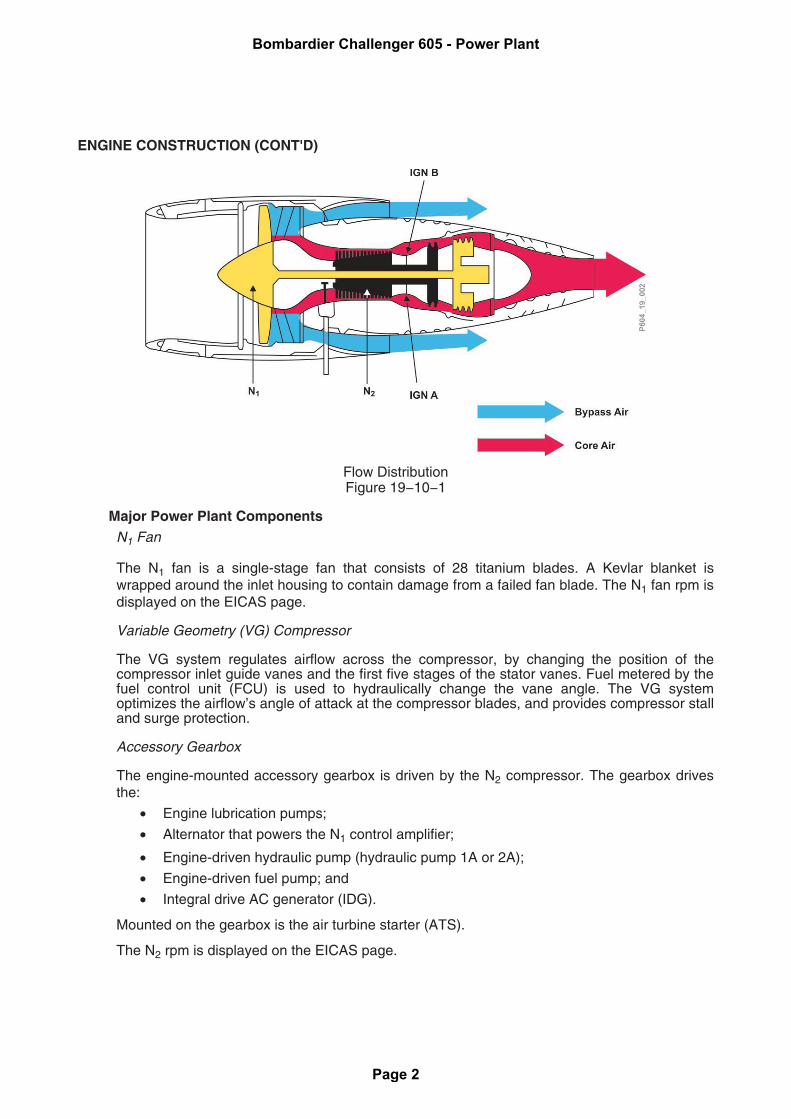
Engine airflow passes through the single-stage fan, and is divided into two airflow paths:
• Bypass air – Air is accelerated by the single-stage N1 fan only, and is ducted around theengine nacelle. Bypass airflow produces approximately 80% of the thrust at takeoff.Thrust reversers are used to divert the bypass air forward to assist in airplane braking onthe ground.
• Core air – Air that is accelerated by the N1 fan enters the N2 core where it iscompressed, mixed with fuel, and ignited. The resulting combustion gases areexhausted through the high-pressure two-stage N2 turbine, which drives the N2assembly. The exhaust gases are then discharged through the low-pressure four-stageN1 turbine to drive the N1 fan. Jet pipe thrust produces approximately 20% of the takeoffthrust.
Bombardier Challenger 605 - Power Plant
Page 1
ENGINE CONSTRUCTION (CONT'D)
Flow DistributionFigure 19−10−1
Major Power Plant ComponentsN1 Fan
The N1 fan is a single-stage fan that consists of 28 titanium blades. A Kevlar blanket iswrapped around the inlet housing to contain damage from a failed fan blade. The N1 fan rpm isdisplayed on the EICAS page.
Variable Geometry (VG) Compressor
The VG system regulates airflow across the compressor, by changing the position of thecompressor inlet guide vanes and the first five stages of the stator vanes. Fuel metered by thefuel control unit (FCU) is used to hydraulically change the vane angle. The VG systemoptimizes the airflow’s angle of attack at the compressor blades, and provides compressor stalland surge protection.
Accessory Gearbox
The engine-mounted accessory gearbox is driven by the N2 compressor. The gearbox drivesthe:
• Engine lubrication pumps;
• Alternator that powers the N1 control amplifier;
• Engine-driven hydraulic pump (hydraulic pump 1A or 2A);
• Engine-driven fuel pump; and
• Integral drive AC generator (IDG).
Mounted on the gearbox is the air turbine starter (ATS).
The N2 rpm is displayed on the EICAS page.
Bombardier Challenger 605 - Power Plant
Page 2
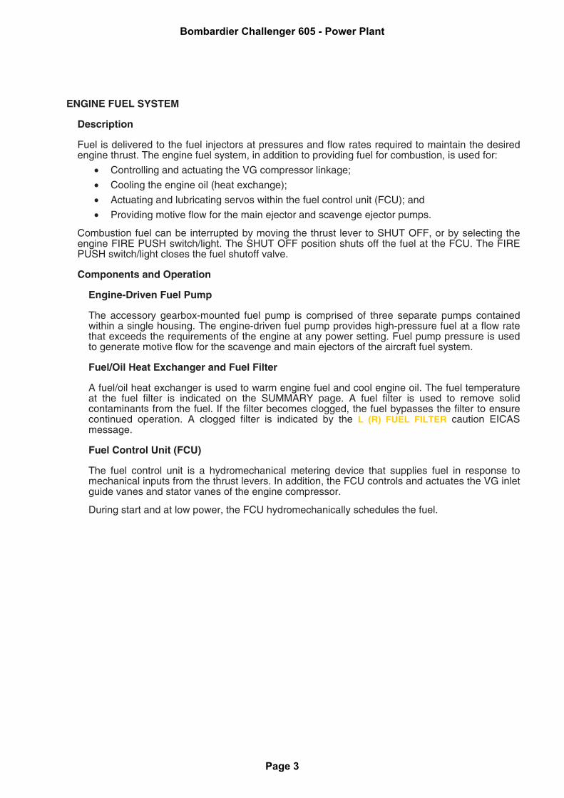
ENGINE FUEL SYSTEM
Description
Fuel is delivered to the fuel injectors at pressures and flow rates required to maintain the desiredengine thrust. The engine fuel system, in addition to providing fuel for combustion, is used for:
• Controlling and actuating the VG compressor linkage;
• Cooling the engine oil (heat exchange);
• Actuating and lubricating servos within the fuel control unit (FCU); and
• Providing motive flow for the main ejector and scavenge ejector pumps.
Combustion fuel can be interrupted by moving the thrust lever to SHUT OFF, or by selecting theengine FIRE PUSH switch/light. The SHUT OFF position shuts off the fuel at the FCU. The FIREPUSH switch/light closes the fuel shutoff valve.
Components and Operation
Engine-Driven Fuel Pump
The accessory gearbox-mounted fuel pump is comprised of three separate pumps containedwithin a single housing. The engine-driven fuel pump provides high-pressure fuel at a flow ratethat exceeds the requirements of the engine at any power setting. Fuel pump pressure is usedto generate motive flow for the scavenge and main ejectors of the aircraft fuel system.
Fuel/Oil Heat Exchanger and Fuel Filter
A fuel/oil heat exchanger is used to warm engine fuel and cool engine oil. The fuel temperatureat the fuel filter is indicated on the SUMMARY page. A fuel filter is used to remove solidcontaminants from the fuel. If the filter becomes clogged, the fuel bypasses the filter to ensurecontinued operation. A clogged filter is indicated by the L (R) FUEL FILTER caution EICASmessage.
Fuel Control Unit (FCU)
The fuel control unit is a hydromechanical metering device that supplies fuel in response tomechanical inputs from the thrust levers. In addition, the FCU controls and actuates the VG inletguide vanes and stator vanes of the engine compressor.
During start and at low power, the FCU hydromechanically schedules the fuel.
Bombardier Challenger 605 - Power Plant
Page 3
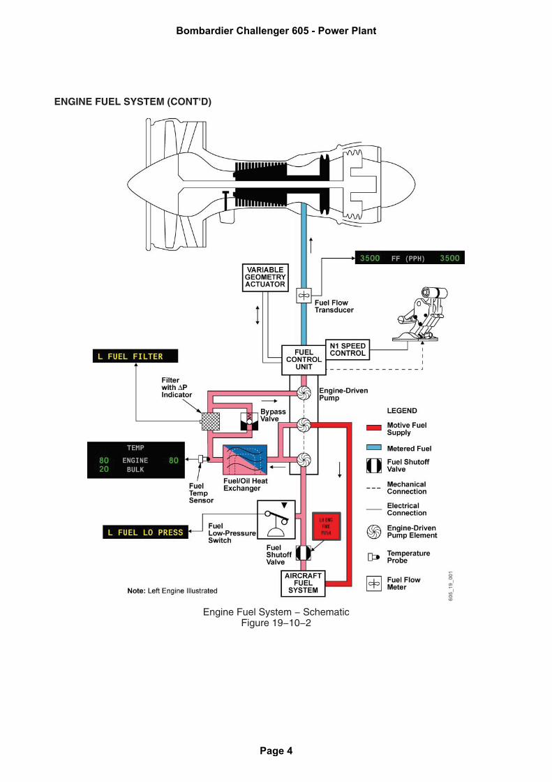
ENGINE FUEL SYSTEM (CONT'D)
Engine Fuel System − SchematicFigure 19−10−2
Bombardier Challenger 605 - Power Plant
Page 4
ENGINE FUEL SYSTEM (CONT'D)
Electronic Control Unit (ECU)
When at high thrust settings, the engine is controlled by an electronic control unit (ECU), whichworks in tandem with the FCU. The ECU is also referred to as the N1 control amplifier. The ECU(or N1 control amplifier) trims the FCU fuel output to maintain a N1 speed schedule for a giventhrust lever setting.
Fuel System OperationN2 Speed Control (N1 <79%)
At low power settings (N1 below 79%), the FCU hydromechanically controls the N2 speed. InN2 mode, the FCU adjusts N2 speed, so that matched movement of the thrust levers producesnearly matched N2 rpm for the engines. N1 speeds, fuel flows, or ITT indications may differbetween engines.
N1 Speed Control (N1 >79%)
At takeoff, climb and cruise power settings (N1 above 79%), the N1 control amplifier controlsthe engine N1 rpm. The amplifier trims the FCU fuel output to achieve the desired N1 rpm.
With the ENG SPEED switches selected to ON, automatic switchover from N2 to N1 speedgoverning occurs at 79% N1. Matched movement of the thrust levers produces nearly matchedN1 rpm and nearly matched thrust between the engines.
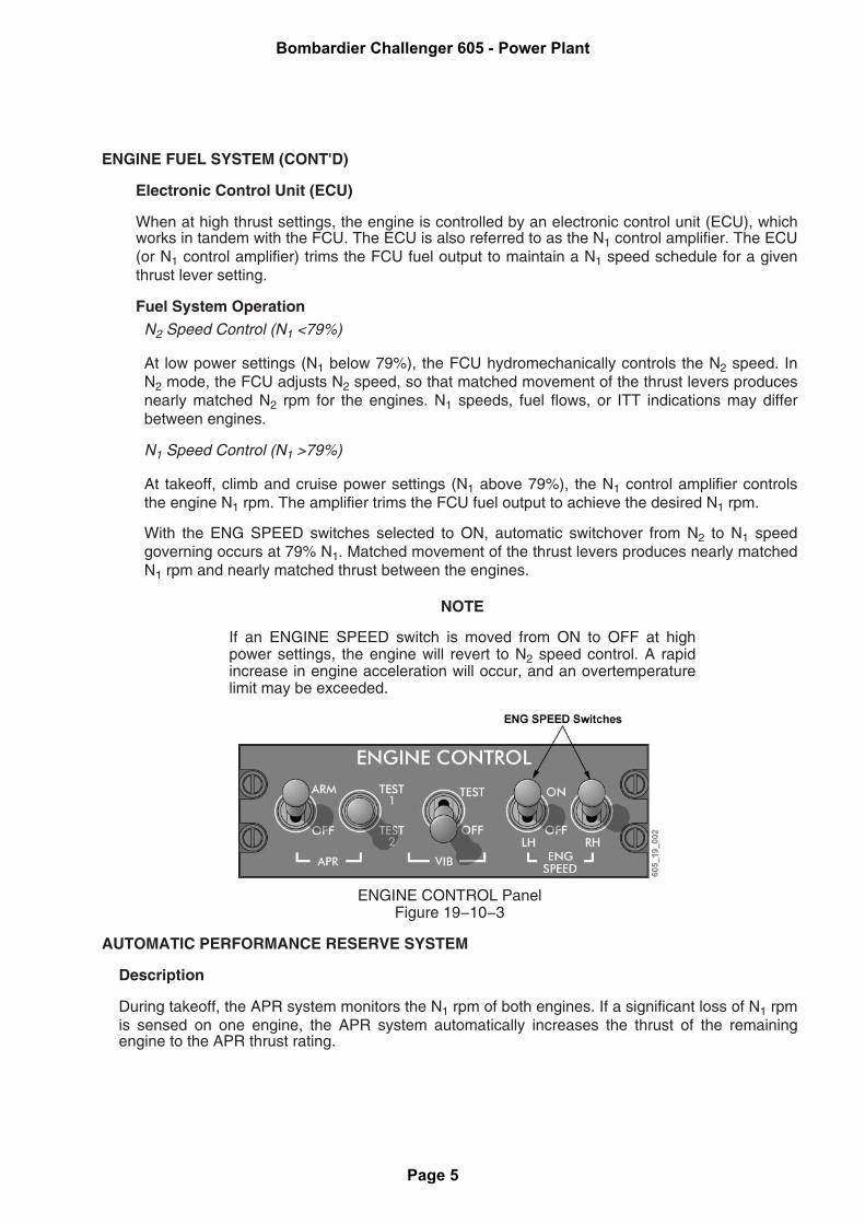
NOTE
If an ENGINE SPEED switch is moved from ON to OFF at highpower settings, the engine will revert to N2 speed control. A rapidincrease in engine acceleration will occur, and an overtemperaturelimit may be exceeded.
ENGINE CONTROL PanelFigure 19−10−3
AUTOMATIC PERFORMANCE RESERVE SYSTEM
Description
During takeoff, the APR system monitors the N1 rpm of both engines. If a significant loss of N1 rpmis sensed on one engine, the APR system automatically increases the thrust of the remainingengine to the APR thrust rating.
Bombardier Challenger 605 - Power Plant
Page 5

AUTOMATIC PERFORMANCE RESERVE SYSTEM (CONT'D)
APR activation does not override thrust lever input to the FCU, nor does it restrict movement of thethrust lever.
Operation
The APR system is armed during takeoff when the APR switch is selected to ARM, and bothengines’ N1 rpm is above 79% (N1 speed mode). This is indicated by the APR ARM advisoryEICAS message. During a normal takeoff, the advisory message is removed five minutes afterAPR arming.
During takeoff, the APR system monitors the N1 rpm of both engines through the DCUs. If an N1rpm drop below 67.6% rpm is sensed at either engine, the system automatically commands bothengines to increase N1 speed. Only the normally operating engine can respond, which it does byincreasing the N1 fan speed by a minimum of 2%. This increase in rpm equates to an increase ofapproximately 500 pounds of thrust. No roll-back in N1 rpm occurs when APR thrust has beencommanded and the APR system times-out.
When the APR system is activated, a green APR icon appears in the center of the N1 gauge of theoperating engine.
APR Test
The APR TEST switches allow the system to be tested on the ground. The system can only betested successfully with the engines operating. Normal system test operation results in the APRTEST 1 (2) OK advisory EICAS message. If the system fails, an APR INOP caution EICASmessage is displayed.
ENGINE CONTROL PanelFigure 19−10−4
ENGINE OIL SYSTEM
Description
Oil from each engine nacelle tank is circulated under pressure to lubricate the engine andaccessory gearbox.
Components and Operation
The gearbox-driven main lubrication pump pressurizes the lubrication system. Oil flows from thepump through an oil filter, a fuel/oil heat exchanger, and continues through the engine sumps tothe bearings and gearbox.
Bombardier Challenger 605 - Power Plant
Page 6
ENGINE OIL SYSTEM (CONT'D)
The oil is returned to the oil tank by the gearbox-driven main lubrication and scavenge pumps. Theoil passes through scavenge screens for filtering prior to the oil pumps. The oil then flows througha chip detector and a deaerator to the tank. Maximum oil consumption is 6.4 ounces or 0.05 USgallons/hour.
Engine oil pressure and temperature indications are presented on the EICAS page. To providesystem redundancy, a pressure switch and separate pressure transmitter are used to monitor theengine oil pressure. When low oil pressure is detected by the pressure switch, the L (R) ENG OILPRESS warning EICAS message is presented. If the pressure transmitter detects low oil pressure,the EICAS digital oil pressure readout changes to red.
Chip detector and impending oil filter bypass indications are provided in the aft equipment bay onjunction box 5 (JB5), but are not presented on EICAS.
Pressurized refilling of the engine oil tanks is provided by a replenishment tank system, located inthe aft equipment bay. The system remotely gauges engine oil tank level, and is used to transferoil to the engine-mounted tanks.
Bombardier Challenger 605 - Power Plant
Page 7
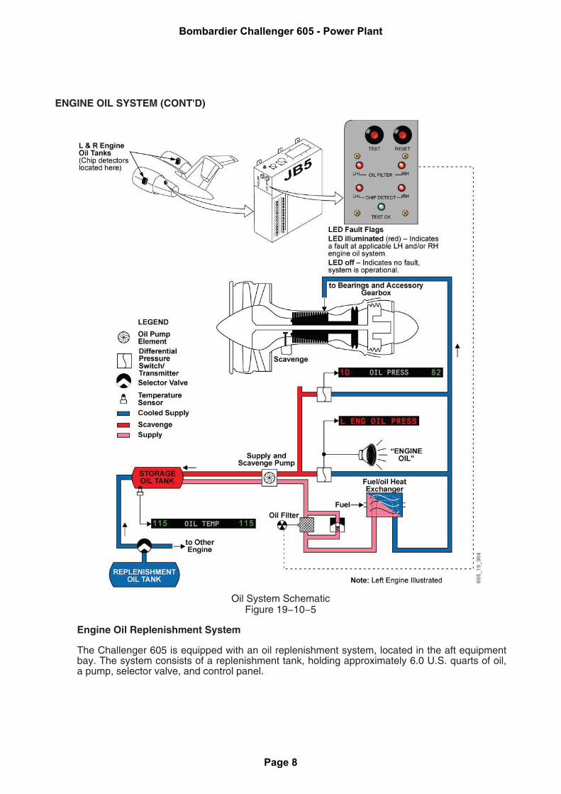
ENGINE OIL SYSTEM (CONT'D)
Oil System SchematicFigure 19−10−5
Engine Oil Replenishment System
The Challenger 605 is equipped with an oil replenishment system, located in the aft equipmentbay. The system consists of a replenishment tank, holding approximately 6.0 U.S. quarts of oil,a pump, selector valve, and control panel.
Bombardier Challenger 605 - Power Plant
Page 8

ENGINE OIL SYSTEM (CONT'D)
If a low oil tank quantity is indicated during the test, the nacelle oil tanks can be filled from thereplenishment tank. Pump and selector valves, located next to the replenishment tank, are usedto transfer oil from the replenishment tank to the applicable engine-mounted tank.
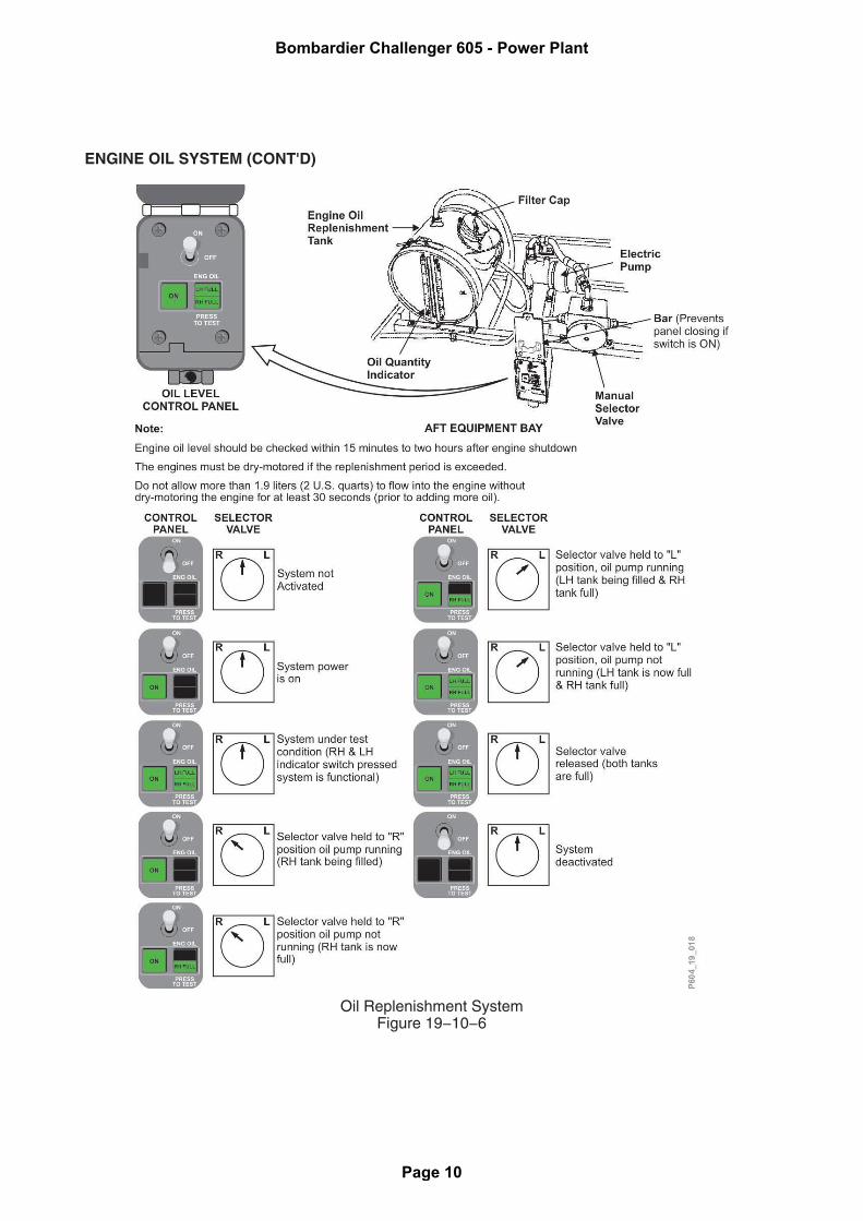
Engine Oil Replenishment Procedure
Oil levels should be checked between 15 minutes to two hours after engine shutdown. Theengines must be motored if the replenishment period is exceeded. Maximum refill allowable is2 U.S. quarts, then the engine must be dry-motored for at least 30 seconds prior to addingmore oil.
Oil replenishment is accomplished as follows:
1. Note the oil quantity on the oil replenishment tank gauge.
2. The system power switch is selected ON, illuminating the green ON light.
3. The ENG OIL PRESS TO TEST switch/light is activated to illuminate (test) the greenLH (RH)-FULL indications.
4. The selector valve is rotated to the L or R position, as required, to pump oil from the oilreplenishment tank to the associated engine oil tank.
5. The selector valve is released when the pump automatically shuts off, and theLH (RH)-FULL legend illuminates. A full level is indicated by the illumination of therespective side green light (LH FULL or RH FULL).
6. The system power switch is selected OFF.
7. Oil quantity used for each engine is noted.
Bombardier Challenger 605 - Power Plant
Page 9
ENGINE OIL SYSTEM (CONT'D)
Oil Replenishment SystemFigure 19−10−6
Bombardier Challenger 605 - Power Plant
Page 10
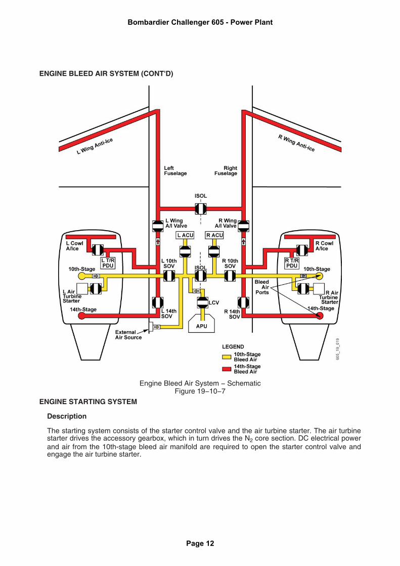
ENGINE BLEED AIR SYSTEM
Description
Engine bleed air is extracted from the 7th, 10th and 14th stages of the engine compressor, andused by the airplane systems below:
• 7th stage: Pressurization of oil seals, and the venting of engine sumps in the lubricationsystem.
• 10th stage: Pneumatic supply to the air conditioning and pressurization systems, andengine starting.
• 14th stage: Pneumatic supply to the engine cowl and wing anti-ice systems, or thrustreverser systems.
Components and Operation
Ducting and check valves are used to direct the flow of bleed air from the engine to the 10th- and14th-stage bleed air manifolds. The nacelle and pylon ducts are monitored for bleed air leakage bythe engine fire and jet pipe overheat detection systems.
For additional information, refer to Chapter 9, Fire Protection, and Chapter 18, Pneumatic System.
Bombardier Challenger 605 - Power Plant
Page 11
ENGINE BLEED AIR SYSTEM (CONT'D)
Engine Bleed Air System − SchematicFigure 19−10−7
ENGINE STARTING SYSTEM
Description
The starting system consists of the starter control valve and the air turbine starter. The air turbinestarter drives the accessory gearbox, which in turn drives the N2 core section. DC electrical powerand air from the 10th-stage bleed air manifold are required to open the starter control valve andengage the air turbine starter.
Bombardier Challenger 605 - Power Plant
Page 12
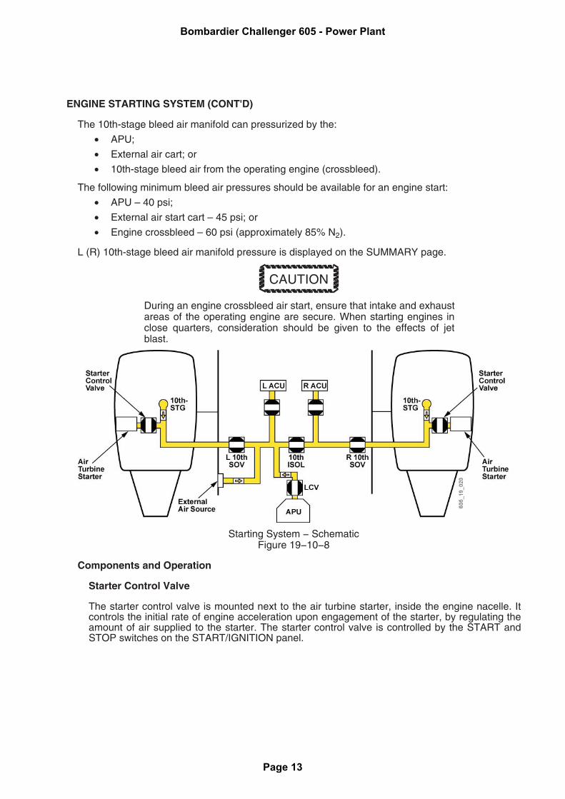
ENGINE STARTING SYSTEM (CONT'D)
The 10th-stage bleed air manifold can pressurized by the:
• APU;
• External air cart; or
• 10th-stage bleed air from the operating engine (crossbleed).
The following minimum bleed air pressures should be available for an engine start:
• APU – 40 psi;
• External air start cart – 45 psi; or
• Engine crossbleed – 60 psi (approximately 85% N2).
L (R) 10th-stage bleed air manifold pressure is displayed on the SUMMARY page.
CAUTION
During an engine crossbleed air start, ensure that intake and exhaustareas of the operating engine are secure. When starting engines inclose quarters, consideration should be given to the effects of jetblast.
Starting System − SchematicFigure 19−10−8
Components and Operation
Starter Control Valve
The starter control valve is mounted next to the air turbine starter, inside the engine nacelle. Itcontrols the initial rate of engine acceleration upon engagement of the starter, by regulating theamount of air supplied to the starter. The starter control valve is controlled by the START andSTOP switches on the START/IGNITION panel.
Bombardier Challenger 605 - Power Plant
Page 13
ENGINE STARTING SYSTEM (CONT'D)
Air Turbine Starter
The air turbine starter is mounted on the accessory gearbox. The air turbine starter convertspneumatic energy into mechanical motion. The starter mechanically engages the accessorygearbox through a clutch, and accelerates the N2 section of the power plant. The starter iscapable of dry-motoring the engine up to approximately 28% N2 rpm. During a normal start, thestarter remains engaged until 55% N2, to assist the engine in accelerating to idle speed. At 55%N2 rpm, the starter control valve closes and the air turbine starter disengages.
For subsequent starts or relights, the starter clutch does not require that engine rotation becompletely stopped before engaging the starter. The air turbine starter may be engaged at anyrpm up to 55% N2 rpm (starter cutout speed).
Starter disengagement may be commanded at any time by pressing the engine STOPswitch/light.
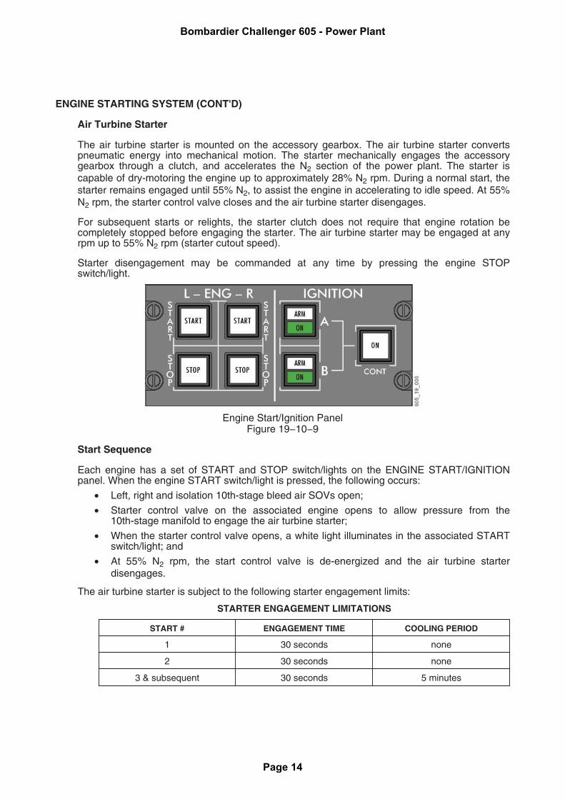
Engine Start/Ignition PanelFigure 19−10−9
Start Sequence
Each engine has a set of START and STOP switch/lights on the ENGINE START/IGNITIONpanel. When the engine START switch/light is pressed, the following occurs:
• Left, right and isolation 10th-stage bleed air SOVs open;
• Starter control valve on the associated engine opens to allow pressure from the10th-stage manifold to engage the air turbine starter;
• When the starter control valve opens, a white light illuminates in the associated STARTswitch/light; and
• At 55% N2 rpm, the start control valve is de-energized and the air turbine starterdisengages.
The air turbine starter is subject to the following starter engagement limits:
STARTER ENGAGEMENT LIMITATIONS
START # ENGAGEMENT TIME COOLING PERIOD
1 30 seconds none
2 30 seconds none
3 & subsequent 30 seconds 5 minutes
Bombardier Challenger 605 - Power Plant
Page 14
ENGINE STARTING SYSTEM (CONT'D)
DRY MOTORING # ENGAGEMENT TIME COOLING PERIOD
1 90 seconds 5 minutes
2 & subsequent 30 seconds 5 minutes
Dry-Motoring
Dry-motoring is performed with ignition off and thrust levers at SHUT OFF.
Dry-motoring may be used for engine ground starts and engine airstarts.
IGNITION SYSTEM
Description
Two independent alternating current (AC) ignition systems are provided for each engine. Eachignition system consists of one ignition exciter and one igniter plug.
Ignition system A is powered by the AC essential bus. Ignition system B is powered by the batterybus through a static inverter.
Operation
There are three ignition system modes:
Normal – Prior to engine start, the ignition is armed by selecting either A or B ignition switch/lightat the START/IGNITION panel. When an ignition system is armed, the corresponding white ARMlight illuminates. Ignition is energized upon starter engagement, and is de-energized at startercutout (55% N2). While an ignition system is energized, the corresponding green ON lightilluminates, and the IGNITION A (B) advisory EICAS message appears.
Continuous ignition – Continuous ignition may be selected by pressing the CONT ignitionswitch/light on the START/IGNITION panel. Both ignitions A and B are energized. Whencontinuous ignition is selected, both green ON lights illuminate, and the IGNITION A/B advisoryEICAS message appears.
Continuous ignition must be used during the following flight conditions:
• Takeoff and landings on contaminated runways;
• Takeoff with high crosswind components (greater than 10 knots);
• Flight through moderate or heavier intensity rain;
• Flight through moderate or heavier intensity turbulence; or
• Flight in the vicinity of thunderstorms.
Autoignition (aerodynamic stall protection) – Automatic activation of continuous ignition isbased upon angle-of-attack (AOA) data. Both systems A and B are energized by the stall warningcomputer, and remain on until the airplane flight attitude is corrected.
Bombardier Challenger 605 - Power Plant
Page 15
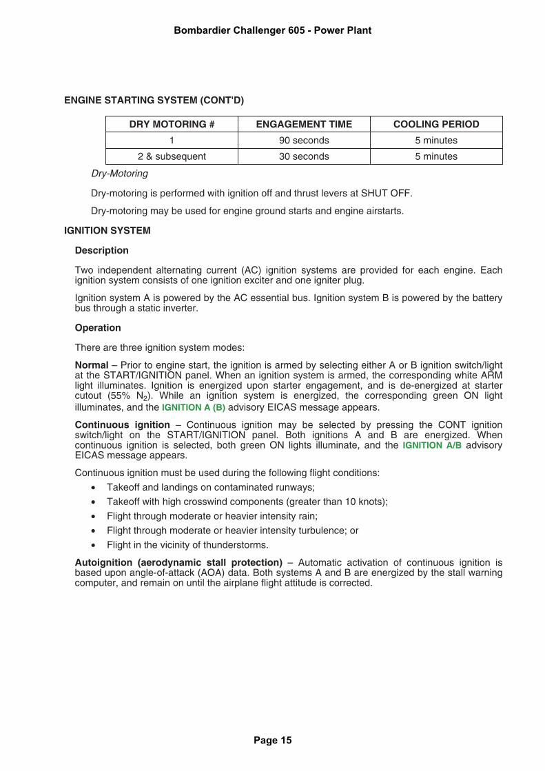
IGNITION SYSTEM (CONT'D)
CAUTION
Activation of the Stall Protection System Test will activate continuousignition.
Both ignition systems A and B are disabled on the associated engine when the L (R) ENGINEFIRE PUSH switch/light is selected. If continuous ignition was in use, the white ON legend of theCONT switch/light will extinguish, but the green ON lights in the switch/lights remain illuminated,and the IGNITION A/B advisory EICAS message remains displayed (to advise the crew thatcontinuous ignition is still active on the unaffected engine).
Ignition SystemFigure 19−10−10
VIBRATION MONITORING SYSTEM
Description
The power plant consists of two major rotating assemblies, the N1 fan and N2 core sections. Eachassembly is continuously monitored for vibration. Indications are displayed on the EICAS page.
Bombardier Challenger 605 - Power Plant
Page 16
VIBRATION MONITORING SYSTEM (CONT'D)
Operation
N1 Fan
N1 fan vibration is displayed as a numeric readout on the EICAS page as FAN VIB. When theN1 vibration level is 2.7 mils or greater, the color of the readout changes to amber. There is noassociated caution EICAS message.
N2 Core
N2 core vibration levels are continuously monitored, but are presented only when vibrationlevels exceed a target value. An amber VIB icon appears in the middle of the N2 gauge whenthe vibration target value is exceeded. There is no associated caution EICAS message.
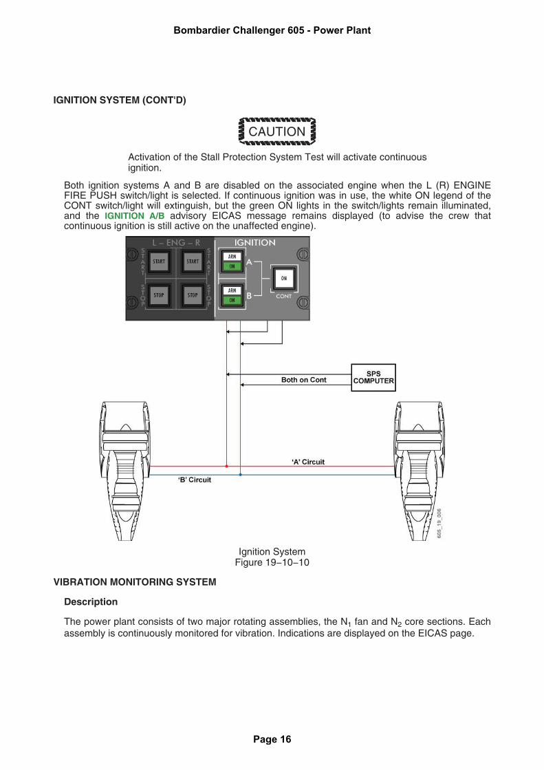
Vibration Monitoring System Test
The system is tested by selecting the VIB switch on the ENGINE CONTROL panel to the TESTposition. In the TEST position, high vibration levels are simulated in the electrical circuitry. Thefollowing indications appear on selection of the ENGINE VIB test switch:
• FAN VIB readouts increase to 3.6 mils, changing from green to amber, passing through2.7 mils; and
• Amber VIB icons appear on the N2 dials.
ENGINE CONTROL PanelFigure 19−10−11
THRUST LEVERS
Description
The thrust lever quadrant contains the thrust levers, thrust reverse levers, microswitches, andinternal locks and stops necessary to control the engines in forward and reverse thrust.
Operation
Thrust Levers
Most functions of the thrust levers are conventional in operation. Thrust lever quadrant settingsare SHUT OFF, IDLE, and MAX POWER.
Bombardier Challenger 605 - Power Plant
Page 17
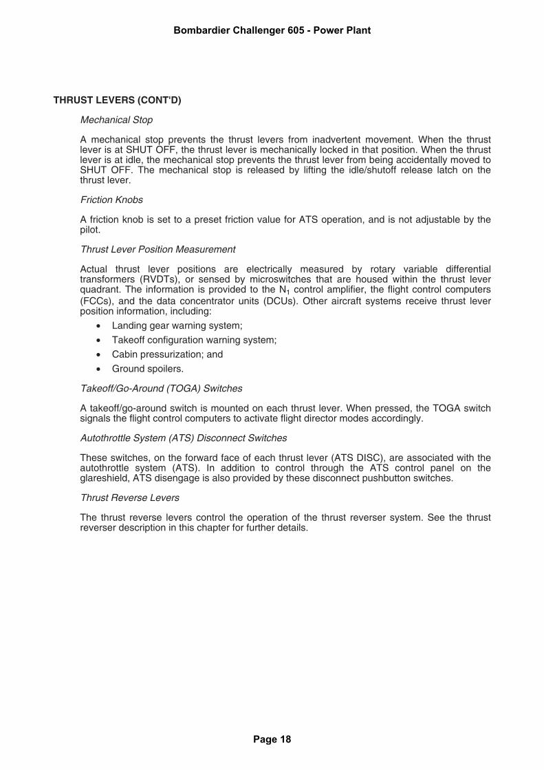
THRUST LEVERS (CONT'D)
Mechanical Stop
A mechanical stop prevents the thrust levers from inadvertent movement. When the thrustlever is at SHUT OFF, the thrust lever is mechanically locked in that position. When the thrustlever is at idle, the mechanical stop prevents the thrust lever from being accidentally moved toSHUT OFF. The mechanical stop is released by lifting the idle/shutoff release latch on thethrust lever.
Friction Knobs
A friction knob is set to a preset friction value for ATS operation, and is not adjustable by thepilot.
Thrust Lever Position Measurement
Actual thrust lever positions are electrically measured by rotary variable differentialtransformers (RVDTs), or sensed by microswitches that are housed within the thrust leverquadrant. The information is provided to the N1 control amplifier, the flight control computers(FCCs), and the data concentrator units (DCUs). Other aircraft systems receive thrust leverposition information, including:
• Landing gear warning system;
• Takeoff configuration warning system;
• Cabin pressurization; and
• Ground spoilers.
Takeoff/Go-Around (TOGA) Switches
A takeoff/go-around switch is mounted on each thrust lever. When pressed, the TOGA switchsignals the flight control computers to activate flight director modes accordingly.
Autothrottle System (ATS) Disconnect Switches
These switches, on the forward face of each thrust lever (ATS DISC), are associated with theautothrottle system (ATS). In addition to control through the ATS control panel on theglareshield, ATS disengage is also provided by these disconnect pushbutton switches.
Thrust Reverse Levers
The thrust reverse levers control the operation of the thrust reverser system. See the thrustreverser description in this chapter for further details.
Bombardier Challenger 605 - Power Plant
Page 18
THRUST LEVERS (CONT'D)
Thrust LeversFigure 19−10−12
THRUST REVERSER SYSTEM
Description
The thrust reverser system is used to assist in stopping the aircraft on landing and during arejected takeoff (RTO). The system is operable on the ground only.
Operation
The thrust reversers are armed when the appropriate switches on the THRUST REVERSER panelare selected to ARM, and the respective 14th-stage bleed air shutoff valves are opened. Whenarmed, a L (R) REV ARMED advisory EICAS message is displayed.
Bombardier Challenger 605 - Power Plant
Page 19
THRUST REVERSER SYSTEM (CONT'D)
Reverse thrust is generated by blocking fan bypass airflow, and redirecting it forward through aseries of cascade vanes. Bleed air, from the 14th stage of the compressor, pneumatically activatesa power drive unit (PDU), which mechanically moves the engine translating cowls rearward bymeans of a flexible driveshaft and ballscrew actuators. As the translating cowl moves rearward,blocker doors rotate to redirect fan airflow forward through the cascade vanes.
Reverser deployment is accomplished by squeezing the thrust reverser triggers and applyingupward pressure on the thrust reverse levers. Thrust reverse lever movement is initially restrictedto approximately 20 degrees by a solenoid stop and a reverse thrust lever lock. This locks thethrust lever in the IDLE position, and prevents thrust from being applied. When the translating cowlreaches full aft travel, the solenoid stop is released, allowing the reverse lever to be operatedthough its full range, and reverse thrust to be applied.
During normal thrust reverser deployment, an amber REV icon appears in the engine N1 gaugewhile the reverser is in transit. When the reverser is fully deployed, the REV icon changes togreen. Reverser deployment is achieved in approximately 5 seconds.
Anti-Ice Disable
On touchdown, or during rejected takeoff with the wing and/or cowl anti-ice system on, theanti-ice systems are automatically disabled while the thrust reversers are activated. Thisdisabling action redirects all 14th-stage bleed air to the thrust reverser PDU to ensure properoperation.
Bombardier Challenger 605 - Power Plant
Page 20
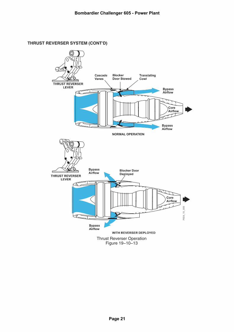
THRUST REVERSER SYSTEM (CONT'D)
Thrust Reverser OperationFigure 19−10−13
Bombardier Challenger 605 - Power Plant
Page 21
THRUST REVERSER SYSTEM (CONT'D)
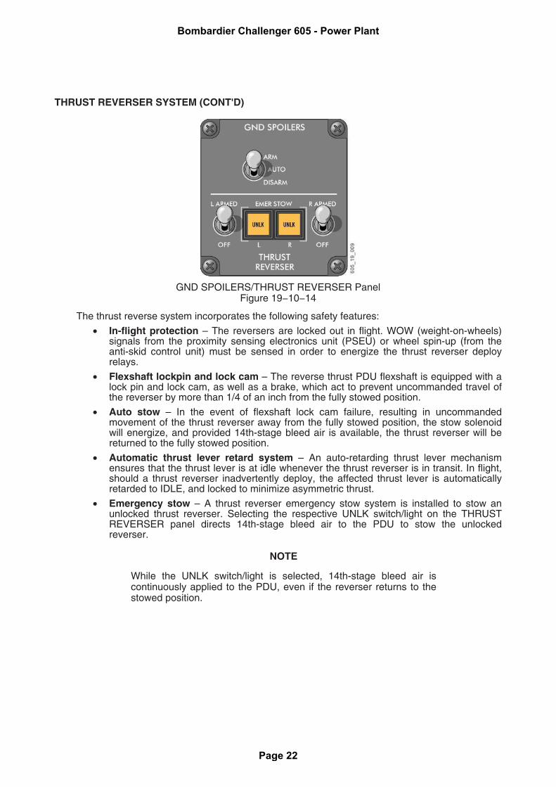
GND SPOILERS/THRUST REVERSER PanelFigure 19−10−14
The thrust reverse system incorporates the following safety features:
• In-flight protection – The reversers are locked out in flight. WOW (weight-on-wheels)signals from the proximity sensing electronics unit (PSEU) or wheel spin-up (from theanti-skid control unit) must be sensed in order to energize the thrust reverser deployrelays.
• Flexshaft lockpin and lock cam – The reverse thrust PDU flexshaft is equipped with alock pin and lock cam, as well as a brake, which act to prevent uncommanded travel ofthe reverser by more than 1/4 of an inch from the fully stowed position.
• Auto stow – In the event of flexshaft lock cam failure, resulting in uncommandedmovement of the thrust reverser away from the fully stowed position, the stow solenoidwill energize, and provided 14th-stage bleed air is available, the thrust reverser will bereturned to the fully stowed position.
• Automatic thrust lever retard system – An auto-retarding thrust lever mechanismensures that the thrust lever is at idle whenever the thrust reverser is in transit. In flight,should a thrust reverser inadvertently deploy, the affected thrust lever is automaticallyretarded to IDLE, and locked to minimize asymmetric thrust.
• Emergency stow – A thrust reverser emergency stow system is installed to stow anunlocked thrust reverser. Selecting the respective UNLK switch/light on the THRUSTREVERSER panel directs 14th-stage bleed air to the PDU to stow the unlockedreverser.
NOTE
While the UNLK switch/light is selected, 14th-stage bleed air iscontinuously applied to the PDU, even if the reverser returns to thestowed position.
Bombardier Challenger 605 - Power Plant
Page 22
CONTROLS AND INDICATORS
The CF 34–3B engine controls consist of the following:
• Thrust levers
• Thrust reversers
• Engine start/ignition panel
• Engine control panel
The EICAS page and SUMMARY page provide analog and digital engine information, and systemwarning/caution and advisory messages.
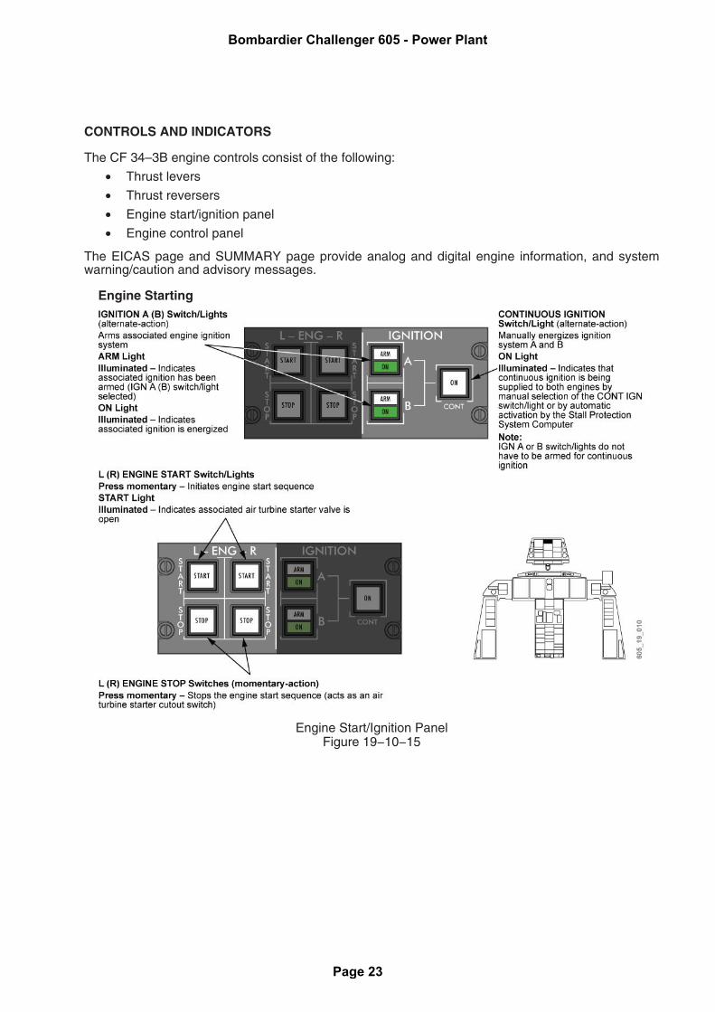
Engine Starting
Engine Start/Ignition PanelFigure 19−10−15
Bombardier Challenger 605 - Power Plant
Page 23
CONTROLS AND INDICATORS (CONT'D)
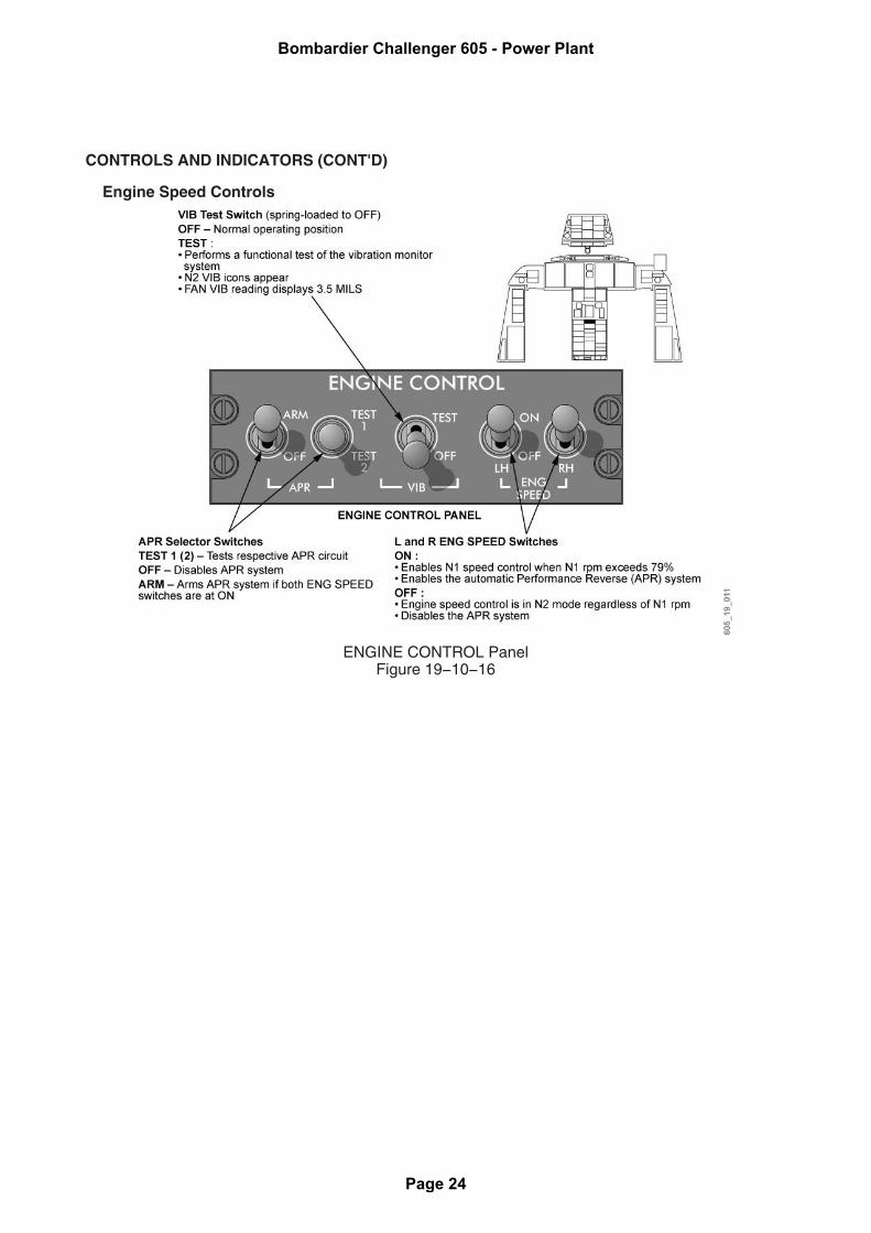
Engine Speed Controls
ENGINE CONTROL PanelFigure 19−10−16
Bombardier Challenger 605 - Power Plant
Page 24

CONTROLS AND INDICATORS (CONT'D)
Thrust Levers
Thrust LeversFigure 19−10−17
Bombardier Challenger 605 - Power Plant
Page 25
CONTROLS AND INDICATORS (CONT'D)
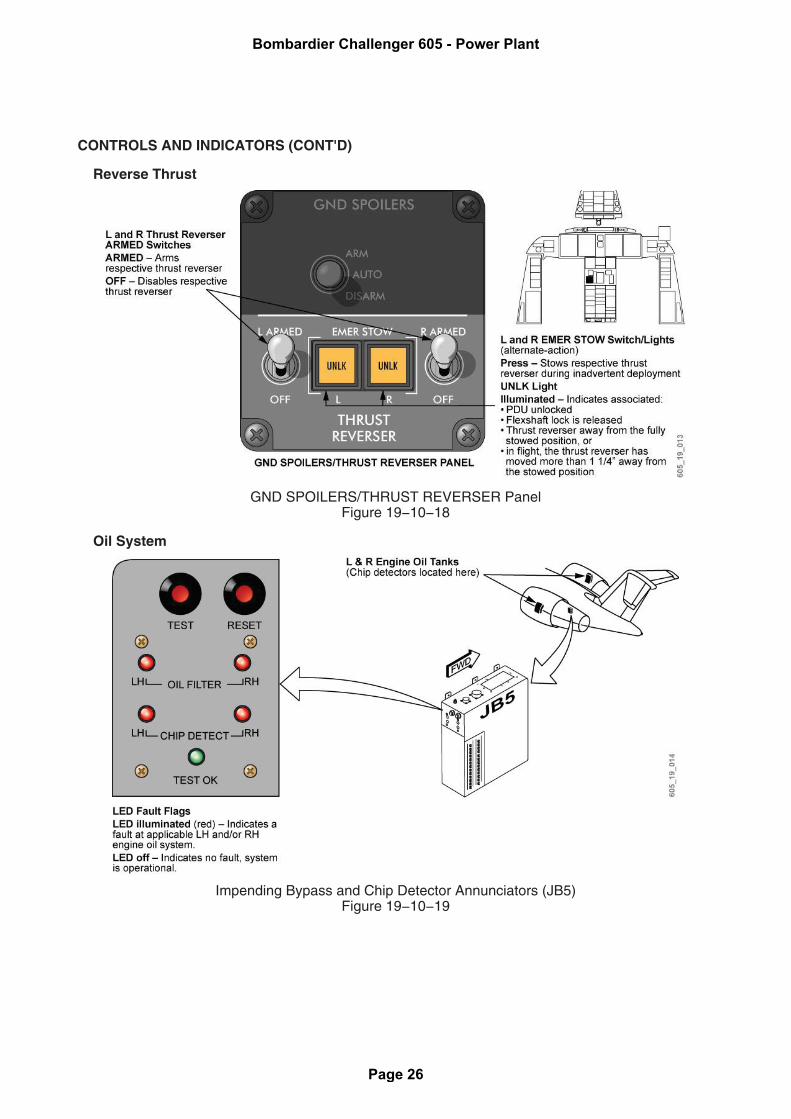
Reverse Thrust
GND SPOILERS/THRUST REVERSER PanelFigure 19−10−18
Oil System
Impending Bypass and Chip Detector Annunciators (JB5)Figure 19−10−19
Bombardier Challenger 605 - Power Plant
Page 26
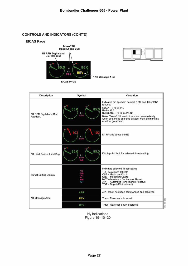
CONTROLS AND INDICATORS (CONT'D)
EICAS Page
N1 IndicationsFigure 19−10−20
Bombardier Challenger 605 - Power Plant
Page 27

CONTROLS AND INDICATORS (CONT'D)
ITT IndicationsFigure 19−10−21
Bombardier Challenger 605 - Power Plant
Page 28
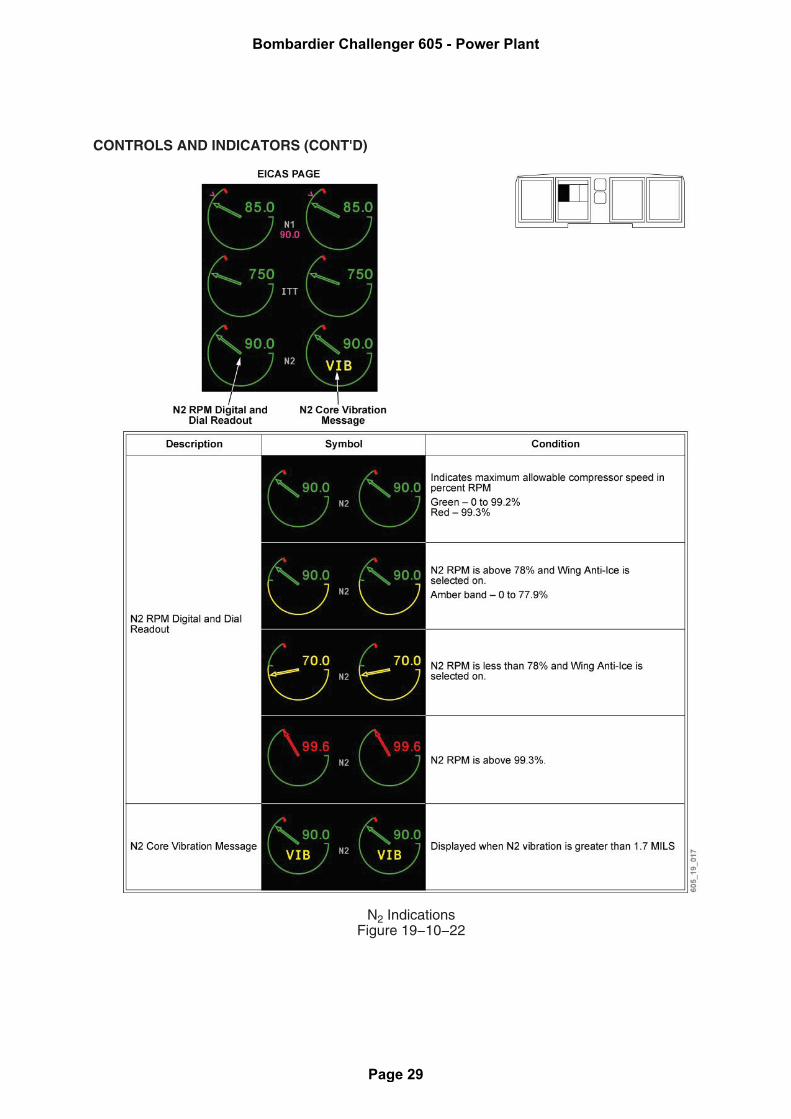
CONTROLS AND INDICATORS (CONT'D)
N2 IndicationsFigure 19−10−22
Bombardier Challenger 605 - Power Plant
Page 29
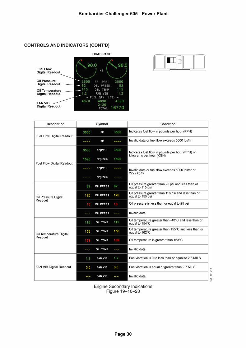
CONTROLS AND INDICATORS (CONT'D)
Engine Secondary IndicationsFigure 19−10−23
Bombardier Challenger 605 - Power Plant
Page 30
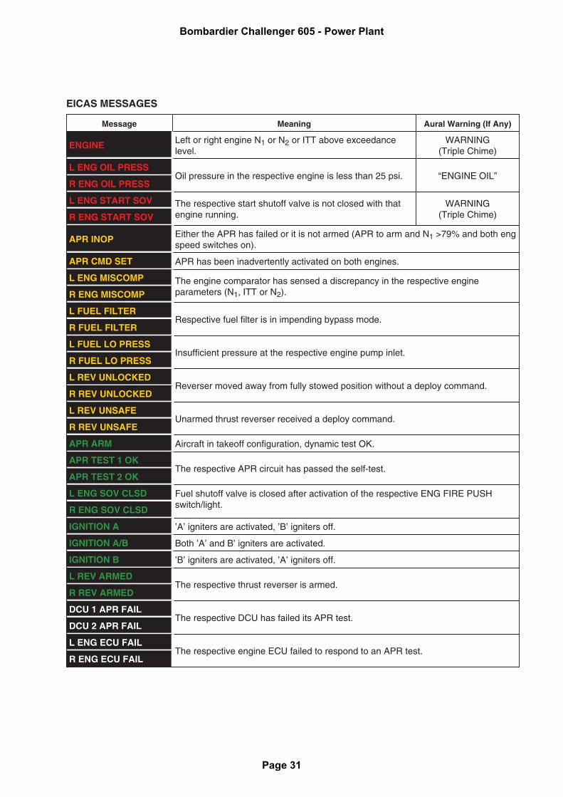
EICAS MESSAGES
Message Meaning Aural Warning (If Any)
ENGINE Left or right engine N1 or N2 or ITT above exceedancelevel.
WARNING(Triple Chime)
L ENG OIL PRESSOil pressure in the respective engine is less than 25 psi. “ENGINE OIL”
R ENG OIL PRESS
L ENG START SOV The respective start shutoff valve is not closed with thatengine running.
WARNING(Triple Chime)R ENG START SOV
APR INOP Either the APR has failed or it is not armed (APR to arm and N1 >79% and both engspeed switches on).
APR CMD SET APR has been inadvertently activated on both engines.
L ENG MISCOMP The engine comparator has sensed a discrepancy in the respective engineparameters (N1, ITT or N2).R ENG MISCOMP
L FUEL FILTERRespective fuel filter is in impending bypass mode.
R FUEL FILTER
L FUEL LO PRESSInsufficient pressure at the respective engine pump inlet.
R FUEL LO PRESS
L REV UNLOCKEDReverser moved away from fully stowed position without a deploy command.
R REV UNLOCKED
L REV UNSAFEUnarmed thrust reverser received a deploy command.
R REV UNSAFE
APR ARM Aircraft in takeoff configuration, dynamic test OK.
APR TEST 1 OKThe respective APR circuit has passed the self-test.
APR TEST 2 OK
L ENG SOV CLSD Fuel shutoff valve is closed after activation of the respective ENG FIRE PUSHswitch/light.R ENG SOV CLSD
IGNITION A ’A’ igniters are activated, ’B’ igniters off.
IGNITION A/B Both ’A’ and B’ igniters are activated.
IGNITION B ’B’ igniters are activated, ’A’ igniters off.
L REV ARMEDThe respective thrust reverser is armed.
R REV ARMED
DCU 1 APR FAILThe respective DCU has failed its APR test.
DCU 2 APR FAIL
L ENG ECU FAILThe respective engine ECU failed to respond to an APR test.
R ENG ECU FAIL
Bombardier Challenger 605 - Power Plant
Page 31
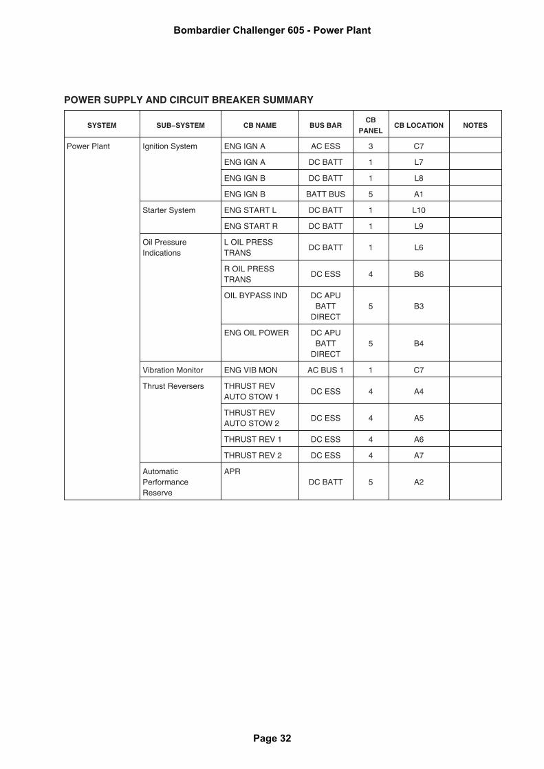
POWER SUPPLY AND CIRCUIT BREAKER SUMMARY
SYSTEM SUB−SYSTEM CB NAME BUS BARCB
PANELCB LOCATION NOTES
Power Plant Ignition System ENG IGN A AC ESS 3 C7
ENG IGN A DC BATT 1 L7
ENG IGN B DC BATT 1 L8
ENG IGN B BATT BUS 5 A1
Starter System ENG START L DC BATT 1 L10
ENG START R DC BATT 1 L9
Oil PressureIndications
L OIL PRESSTRANS
DC BATT 1 L6
R OIL PRESSTRANS
DC ESS 4 B6
OIL BYPASS IND DC APUBATT
DIRECT5 B3
ENG OIL POWER DC APUBATT
DIRECT5 B4
Vibration Monitor ENG VIB MON AC BUS 1 1 C7
Thrust Reversers THRUST REVAUTO STOW 1
DC ESS 4 A4
THRUST REVAUTO STOW 2
DC ESS 4 A5
THRUST REV 1 DC ESS 4 A6
THRUST REV 2 DC ESS 4 A7
AutomaticPerformanceReserve
APRDC BATT 5 A2
Bombardier Challenger 605 - Power Plant
Page 32