CF34-8E Control System
58
Embraer 170/CF34-8E FAMILIARIZATION TRAINING GE Aircraft Engines CONTROL SYSTEM
-
Upload
halartgacm -
Category
Documents
-
view
800 -
download
34
Transcript of CF34-8E Control System

Embraer 170/CF34-8EFAMILIARIZATION TRAINING
GE Aircraft Engines
CONTROL SYSTEM


Control System Design Philosophy• Redundant, engine critical electrical systems
– Dual channel FADEC (full authority digital electronic control) – Dual cables, connectors, torque motors, solenoids and sensors– Dual FADEC power supplies
• Redundant aircraft interfaces– Dual aircraft data busses (ARINC 429)– Dual throttle inputs
– Dual 28 Vdc aircraft backup power• Fail operational control system
– No significant change in power for any single electrical failure from a full up system
– Reversionary modes provide thrust for multiple failures• Time Limited Dispatch Capable
– Capable of short and long term dispatch including one FADEC channel failed

FADECA
FADECB
P0
P0
P3
P3
T2 PMA N1N2
MFP OBVVGACT
FMU
T4.5
T4.5
GMOSWITCH
TRHALF
TRHALF
FADEC

FADEC
Vibe Isolated Mounts
Test Connector
(J5)
Aircraft Connectors
(J1, J2)Engine
Connectors (J3, J4)
Pressure Inputs
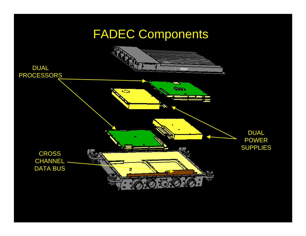
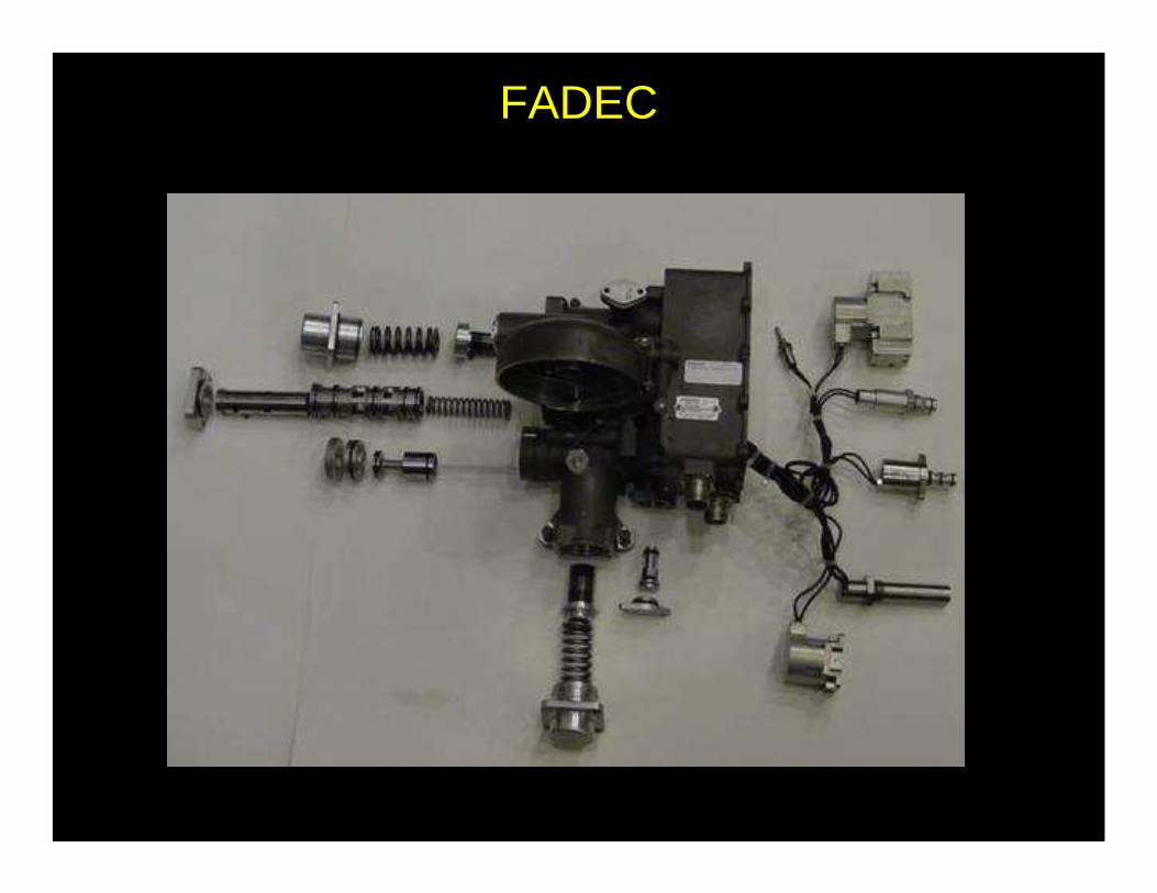
FADEC Components
DUALPROCESSORS
DUALPOWER
SUPPLIESCROSS
CHANNELDATA BUS

PROCESSOR A
PROCESSOR B
POWER SUPPLY B
POWER SUPPLY A

P0 SENSORS
P3 SENSORS

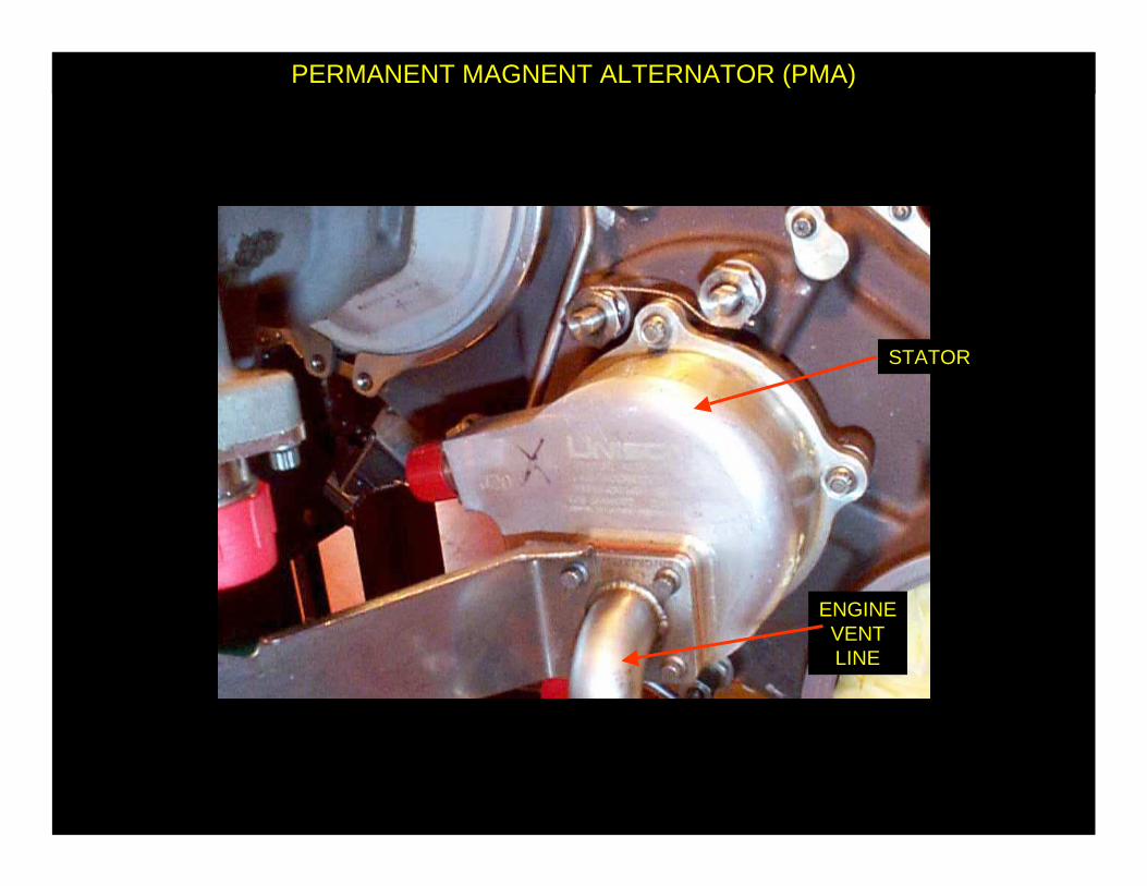
STATOR
PERMANENT MAGNENT ALTERNATOR (PMA)
FADECCONNECTIONS
ENGINEVENTLINE
– Provides power for FADEC channels above 50 % N2– Provides N2 speed signal to FADEC
– Provides N2 speed signal for Vibration System
STATOR
PERMANENT MAGNENT ALTERNATOR (PMA)
ENGINEVENTLINE

MAIN FUEL PUMP
N2 SENSOR – MAIN FUEL PUMP
CONNECTIONSTO FADEC
N2 SPEED SENSOR

MAIN FUEL PUMP SHAFT
N2 SENSOR – MAIN FUEL PUMP
CONNECTIONSTO FADEC
MAGNETIC SENSOR

T2SENSOR
T2 FAN INLET TEMPERATURE SENSOR
FADECCONNECTIONS
– Provides Temperature Input for FADEC channels– Electrically heated for anti-ice
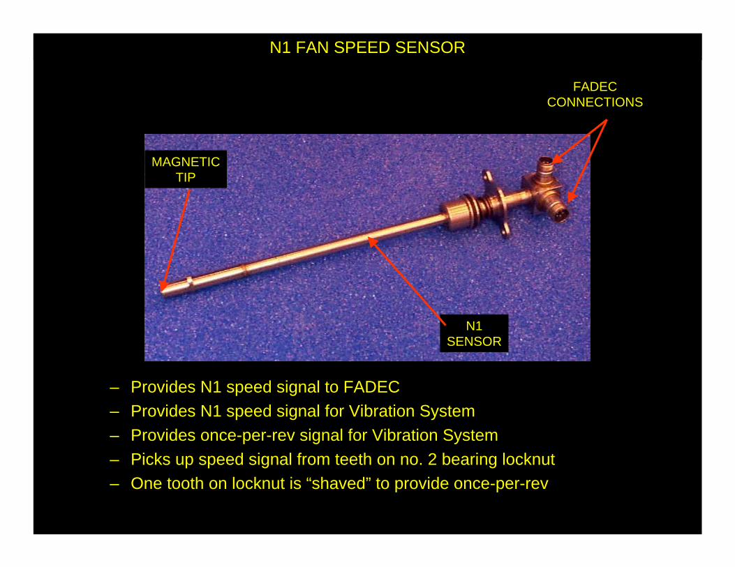
N1SENSOR
N1 FAN SPEED SENSOR
FADECCONNECTIONS
MAGNETICTIP
– Provides N1 speed signal to FADEC– Provides N1 speed signal for Vibration System
– Provides once-per-rev signal for Vibration System– Picks up speed signal from teeth on no. 2 bearing locknut– One tooth on locknut is “shaved” to provide once-per-rev
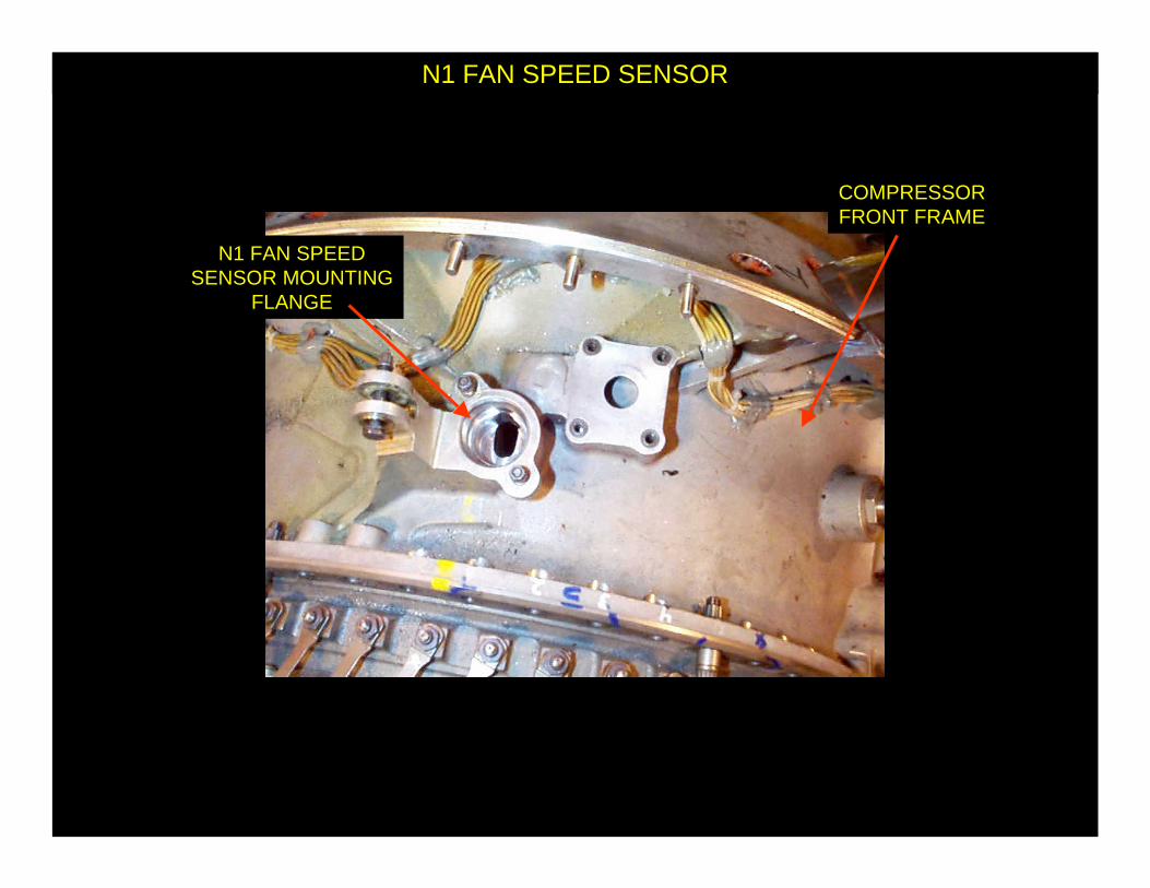
N1 FAN SPEED SENSOR
COMPRESSORFRONT FRAME
N1 FAN SPEEDSENSOR MOUNTING
FLANGE

N1 FAN SPEED SENSOR
NO. 2 BEARINGLOCKNUT
FAN SPEEDSENSORFLANGE

T4.5 THERMOCOUPLES
THERMOCOUPLE
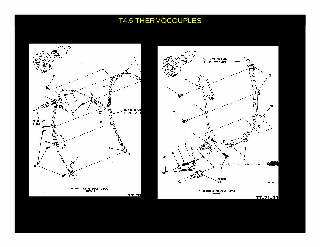
T4.5 THERMOCOUPLES

AUTOTHROTTLEQUICK DISCONNECT
BUTTON
THROTTLE QUADRANT ASSEMBLY (TQA)
TAKEOFF /GO AROUND
BUTTON
FORWARD THRUSTLEVER
START / CONTINUOUSIGNITION BUTTON
MASTERLEVER
SWITCH
MASTERSELECTOR
SWITCH
REVERSE THRUSTLEVER
(PIGGYBACK)

ENGINE CONTROL PANEL
START / CONTINUOUSIGNITION BUTTON
MASTERLEVER
SWITCH
MASTERSELECTOR
SWITCH

VG SERVOVALVE
FMV SERVOVALVE
IMPENDINGBYPASSSENSOR
OVERSPEEDSOLENOID
FUEL TEMP SENSOR
FMVTRANSDUCER
FADEC
FADEC
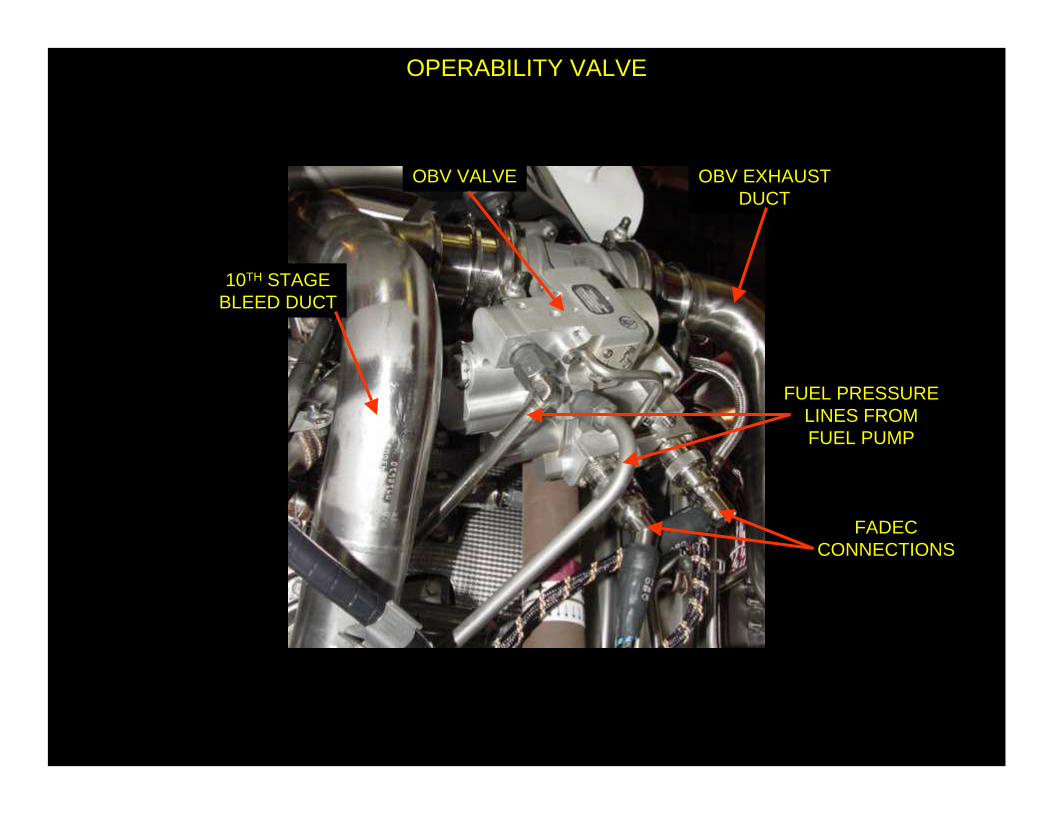
OPERABILITY VALVE
FUEL PRESSURELINES FROMFUEL PUMP
OBV VALVE
FADECCONNECTIONS
10TH STAGEBLEED DUCT
OBV EXHAUSTDUCT

OPERABILITY VALVE
OBV EXHAUST
OBV VALVE

MASTER ACTUATOR
VARIABLE GEOMETRY ACTUATORS
SLAVE ACTUATOR
LINEAR VARIABLEDIFFERENTIALTRANSDUCER
(LVDT)
– Opens and closes variable geometry vanes in HPC– Helps prevent compressor surges and stalls
– Fuel powered– Master actuator has position feedback (LVDT)

MASTER ACTUATOR
VARIABLE GEOMETRY ACTUATORS
CONNECTIONTO ACTUATOR
SHAFT
LINEAR VARIABLEDIFFERENTIALTRANSDUCER
(LVDT)
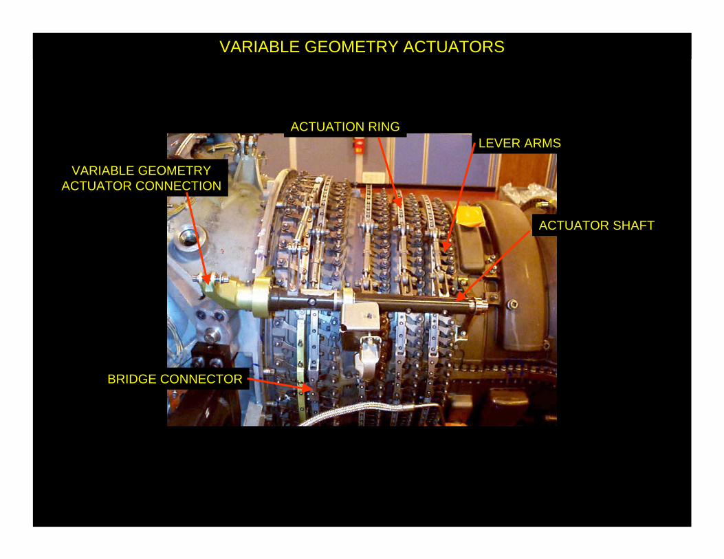
VARIABLE GEOMETRY ACTUATORS
ACTUATOR SHAFT
VARIABLE GEOMETRYACTUATOR CONNECTION
LEVER ARMSACTUATION RING
BRIDGE CONNECTOR

ENGINE STARTING
IGNITION LEAD CONNECTORAIRCRAFTCIRCUIT
CONNECTOR
IGNITION EXCITER
• Converts 115 VAC, 400 Hz to Pulsating DC for Engine Start• Powered by Aircraft Circuit under FADEC control• Two per engine

ENGINE STARTING
IGNITION LEADS
EXCITERS

ENGINE STARTING
IGNITION LEADIGNITER
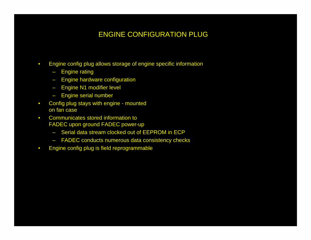
ENGINE CONFIGURATION PLUG
• Engine config plug allows storage of engine specific information– Engine rating– Engine hardware configuration– Engine N1 modifier level– Engine serial number
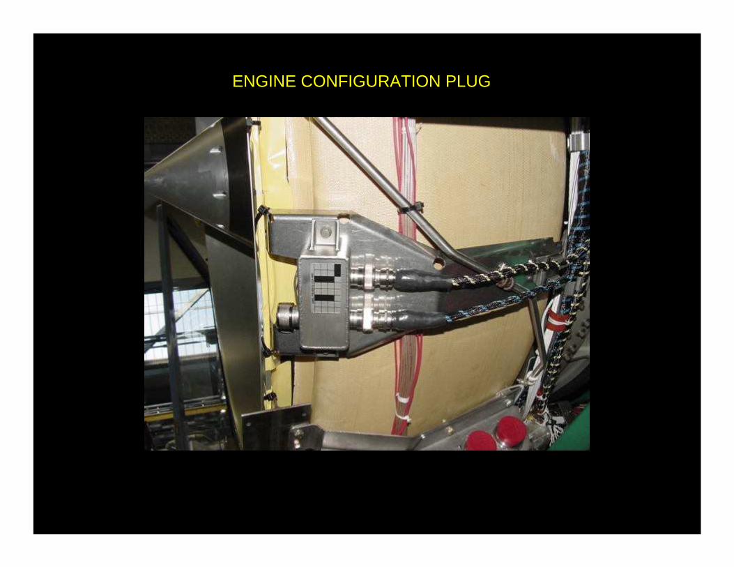
• Config plug stays with engine - mountedon fan case
• Communicates stored information toFADEC upon ground FADEC power-up
– Serial data stream clocked out of EEPROM in ECP– FADEC conducts numerous data consistency checks
• Engine config plug is field reprogrammable
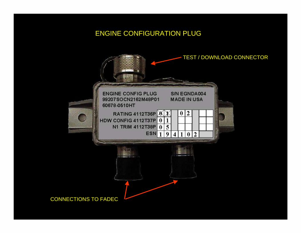
ENGINE CONFIGURATION PLUG
CONNECTIONS TO FADEC
TEST / DOWNLOAD CONNECTOR
ENGINE CONFIGURATION PLUG
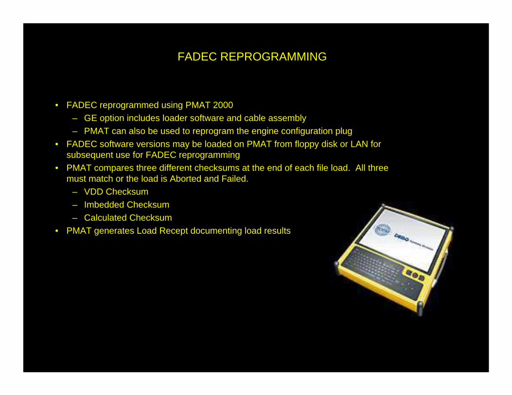
FADEC REPROGRAMMING
• FADEC reprogrammed using PMAT 2000– GE option includes loader software and cable assembly– PMAT can also be used to reprogram the engine configuration plug
• FADEC software versions may be loaded on PMAT from floppy disk or LAN for subsequent use for FADEC reprogramming
• PMAT compares three different checksums at the end of each file load. All three must match or the load is Aborted and Failed.
– VDD Checksum– Imbedded Checksum– Calculated Checksum
• PMAT generates Load Recept documenting load results

• Start discrete from cockpit initiates starter• MAU fully controls starter
– Reads cockpit start discrete– Energizes starter air valve solenoid– Cuts out starter at 53% N2
• Master lever controls fuel flow and ignition via the FADEC– Throttle moved from shutoff initiates fuel flow and ignition– fuel flow held off until 20% N2– on ground, FADEC alternates igniters on successive starts
• FADEC controls start to N2 acceleration (Ndot)• FADEC will terminate start on ground for
– hot start– hung start
• Starter air valve may be manually opened and closed
ENGINE STARTING
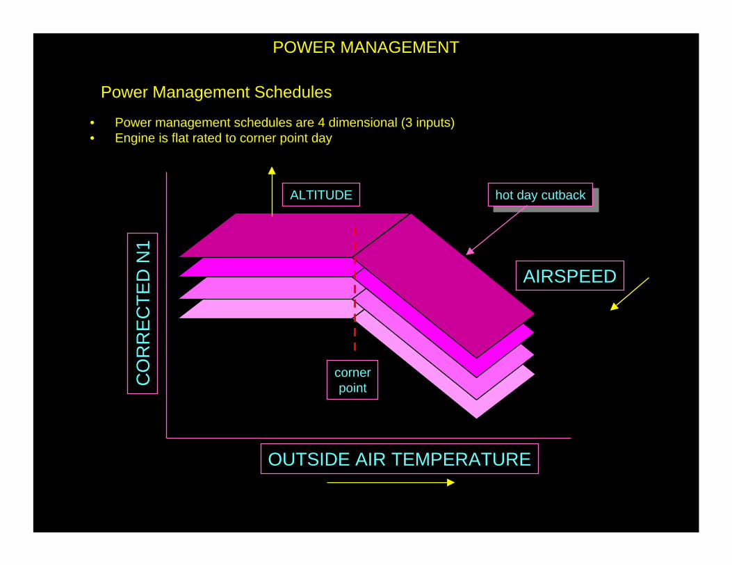
Power Management Schedules
CO
RR
EC
TE
D N
1
OUTSIDE AIR TEMPERATURE
ALTITUDE hot day cutbackhot day cutback
AIRSPEED
cornerpoint
• Power management schedules are 4 dimensional (3 inputs)• Engine is flat rated to corner point day
POWER MANAGEMENT
POWER MANAGEMENT
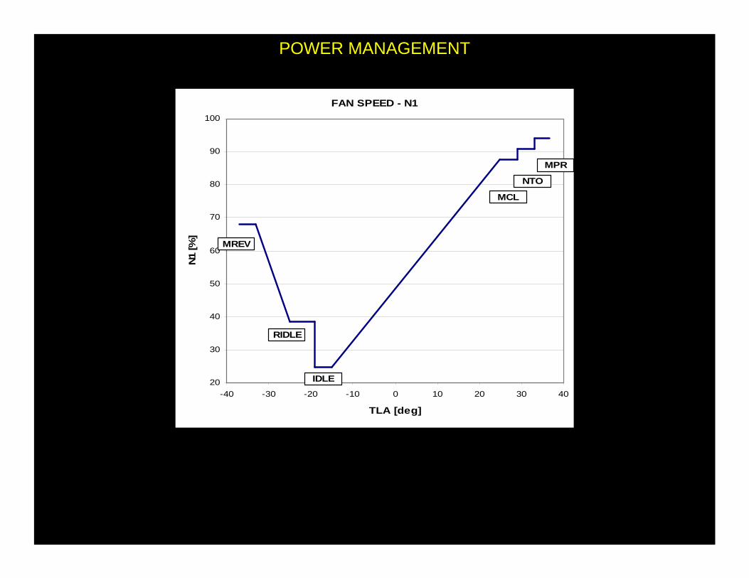
FAN SPEED - N1
20
30
40
50
60
70
80
90
100
-40 -30 -20 -10 0 10 20 30 40
TLA [deg]
N1
[%]
MCL
IDLE
RIDLE
MREV
NTO
MPR

Ignitor A has been commanded on
Ignitor B has been commanded on
Ignitors A and B have been commanded on
Ignitors A and B in OFF

POWER MANAGEMENT
IDLE Selection
When TL is at forward IDLE detent, different thrust schedules are available depending on flight phase:
• Flight IDLE: is selected when WOW is false, it is determined by either min PS3, minimum
N2K or minimum WF whichever is more limiting
• Approach IDLE: is selected when WOW is false and APPROACH bit is set, it is determined
as minimum N2K to ensure acceptable IDLE - Go Around transients
• Landing IDLE: is selected when WOW is true for less than 5 seconds and TRAS is stowed.
Its purpose is to keep N2 relatively high in order to minimize transition time to Reverse IDLE
(that is higher) without penalizing too much landing distance if TRAS is not operated
• Ground IDLE: is selected when WOW is true for more than 5 seconds
When TL is at Reverse IDLE detent engine control is scheduled on N2K values that are defined to
keep core speed enough high to allow acceptable transition time to MAX REV thrust setting
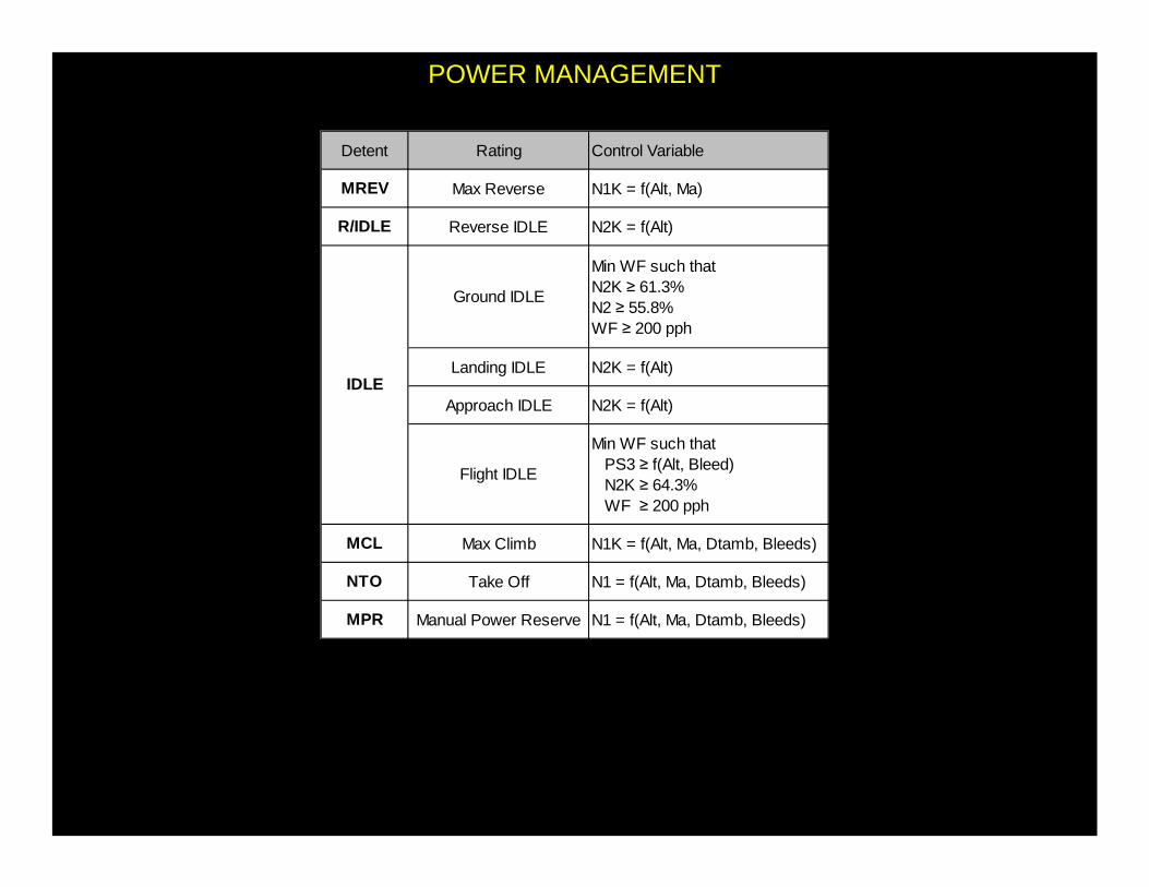
Detent Rating Control Variable
MREV Max Reverse N1K = f(Alt, Ma)
R/IDLE Reverse IDLE N2K = f(Alt)
Ground IDLE
Min WF such thatN2K ≥ 61.3%N2 ≥ 55.8%WF ≥ 200 pph
Landing IDLE N2K = f(Alt)
Approach IDLE N2K = f(Alt)
Flight IDLE
Min WF such that PS3 ≥ f(Alt, Bleed) N2K ≥ 64.3% WF ≥ 200 pph
MCL Max Climb N1K = f(Alt, Ma, Dtamb, Bleeds)
NTO Take Off N1 = f(Alt, Ma, Dtamb, Bleeds)
MPR Manual Power Reserve N1 = f(Alt, Ma, Dtamb, Bleeds)
IDLE
POWER MANAGEMENT

Takeoff Thrust – Normal
N1 SPEED VARIED AS FUNCTION OF:
ALTITUDE
&
TEMPERATURE
TO MAINTAIN CONSTANT TAKEOFFTHRUST OF 12700 LBS
POWER MANAGEMENT

�Selected via MCDU
�Possibilities:
•TO-1, TO-2, TO-3
•CLB-1, CLB-2
•CRZ
•CON
•GA
THRUST RATING
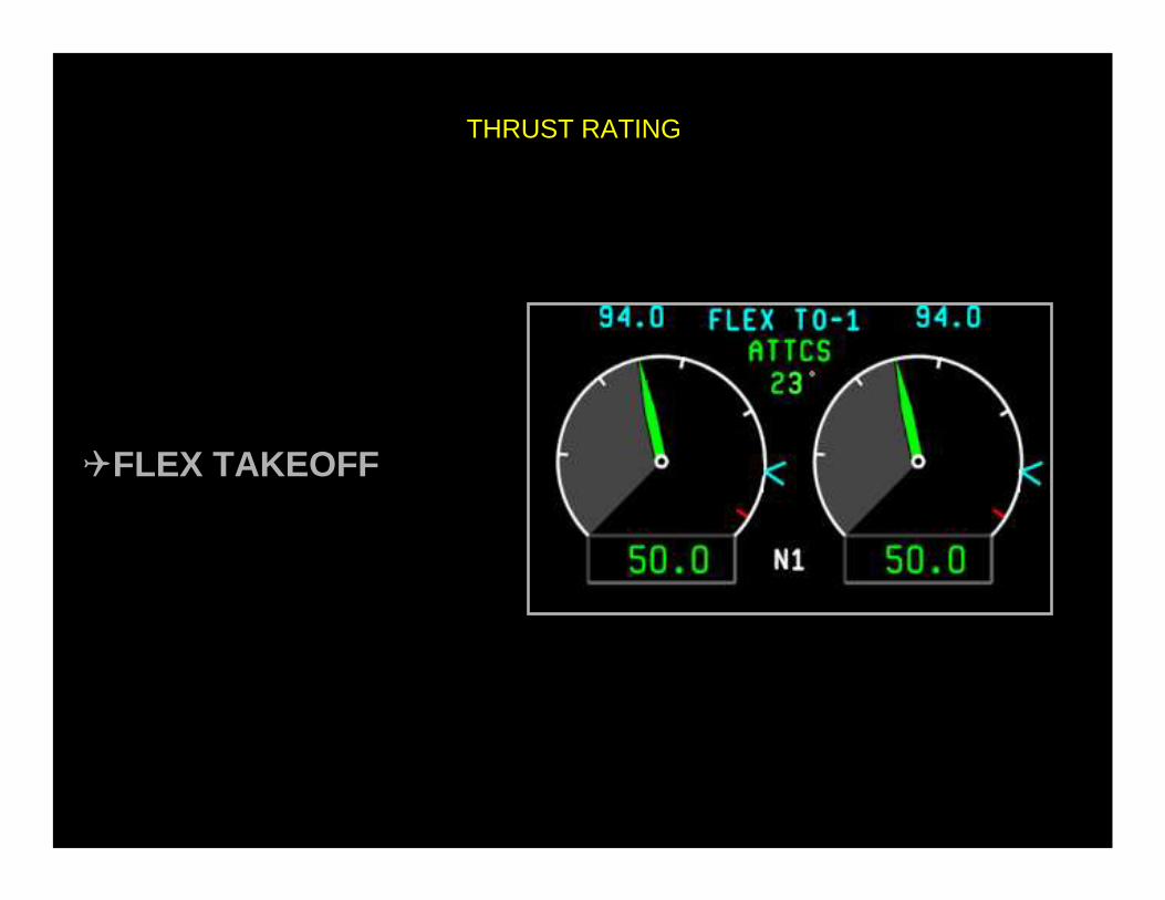
�FLEX TAKEOFF
THRUST RATING

Takeoff Thrust – Flex Takeoff
hot day cutbackhot day cutback
• Pilot sets Delta Ambient Temperature• New Temperature Sets Power Schedule Past Corner Point• Thrust Is Derated – Simulating Hot Day Cutback
ActualOAT
FlexOATC
OR
RE
CT
ED
N1

POWER MANAGEMENTFlexible Take Off Thrust
• FADEC have the capability to provide reduced thrust at NTO flat. This is obtained by pilot input of a Flex TO
Assumed Temperature.
• This temperature is used by FADEC instead of actual SAT to determine NTO thrust and is echoed back to the
cockpit
• Initial entry of a Flex TO Temperature is possible when all the following condition are met:
– TLA at IDLE
– WOW true for at least 1 minute
– Airspeed < 65 Kts
• Once Accepted Flex TO Temperature can be modified until a Locking Flag is set. Lock is set when any of the
following condition occur:
– TLA at MCL or NTO flats
– WOW transition from True to False
– Aircraft Speed first exceeds 65 Kts and remains above 45 Kts for more than 0.480 sec.
• Flex Mode (Lock and Temperature) is then cleared when any of the following condition occur:
– TL moved from NTO flat (either direction)
– APR activated
– Airspeed > 65 Kts and TL below NTO flat
– WAI activated
POWER MANAGEMENT
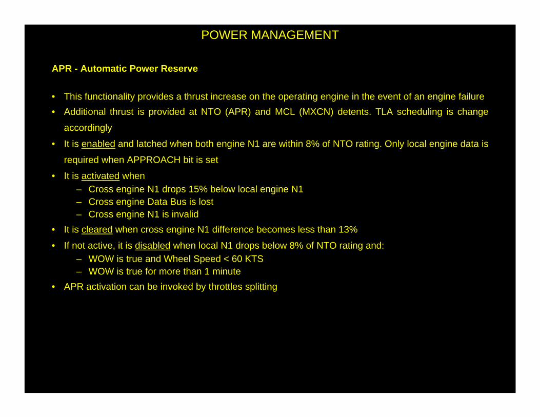
APR - Automatic Power Reserve
• This functionality provides a thrust increase on the operating engine in the event of an engine failure
• Additional thrust is provided at NTO (APR) and MCL (MXCN) detents. TLA scheduling is change
accordingly
• It is enabled and latched when both engine N1 are within 8% of NTO rating. Only local engine data is
required when APPROACH bit is set
• It is activated when – Cross engine N1 drops 15% below local engine N1– Cross engine Data Bus is lost– Cross engine N1 is invalid
• It is cleared when cross engine N1 difference becomes less than 13%
• If not active, it is disabled when local N1 drops below 8% of NTO rating and:– WOW is true and Wheel Speed < 60 KTS– WOW is true for more than 1 minute
• APR activation can be invoked by throttles splitting
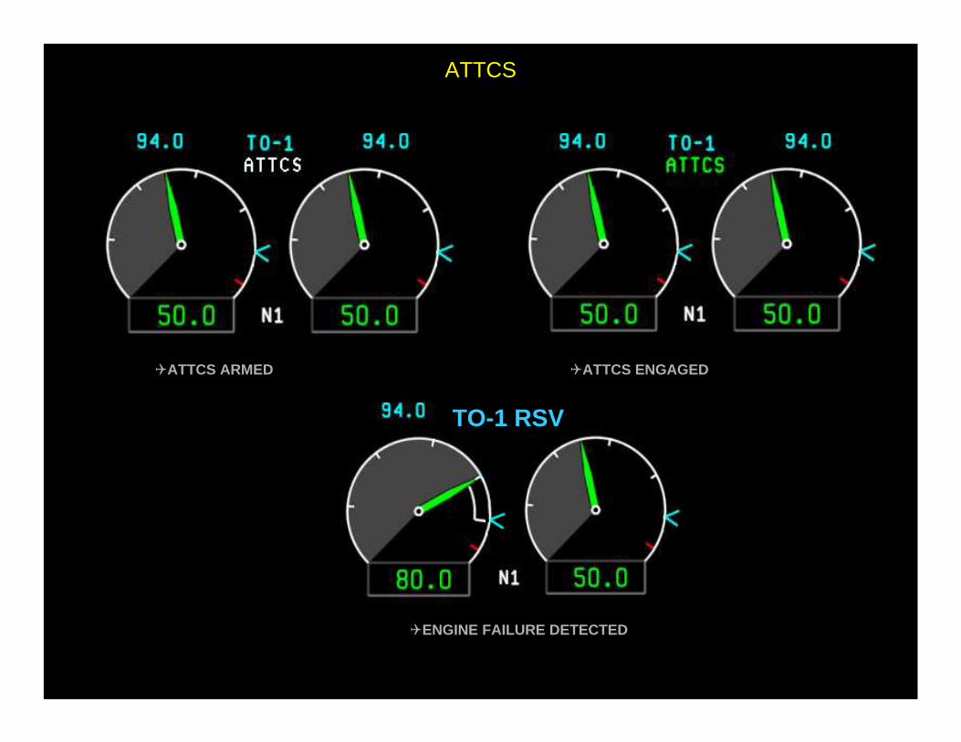
ATTCS
�ATTCS ARMED �ATTCS ENGAGED
TO-1 RSV
�ENGINE FAILURE DETECTED
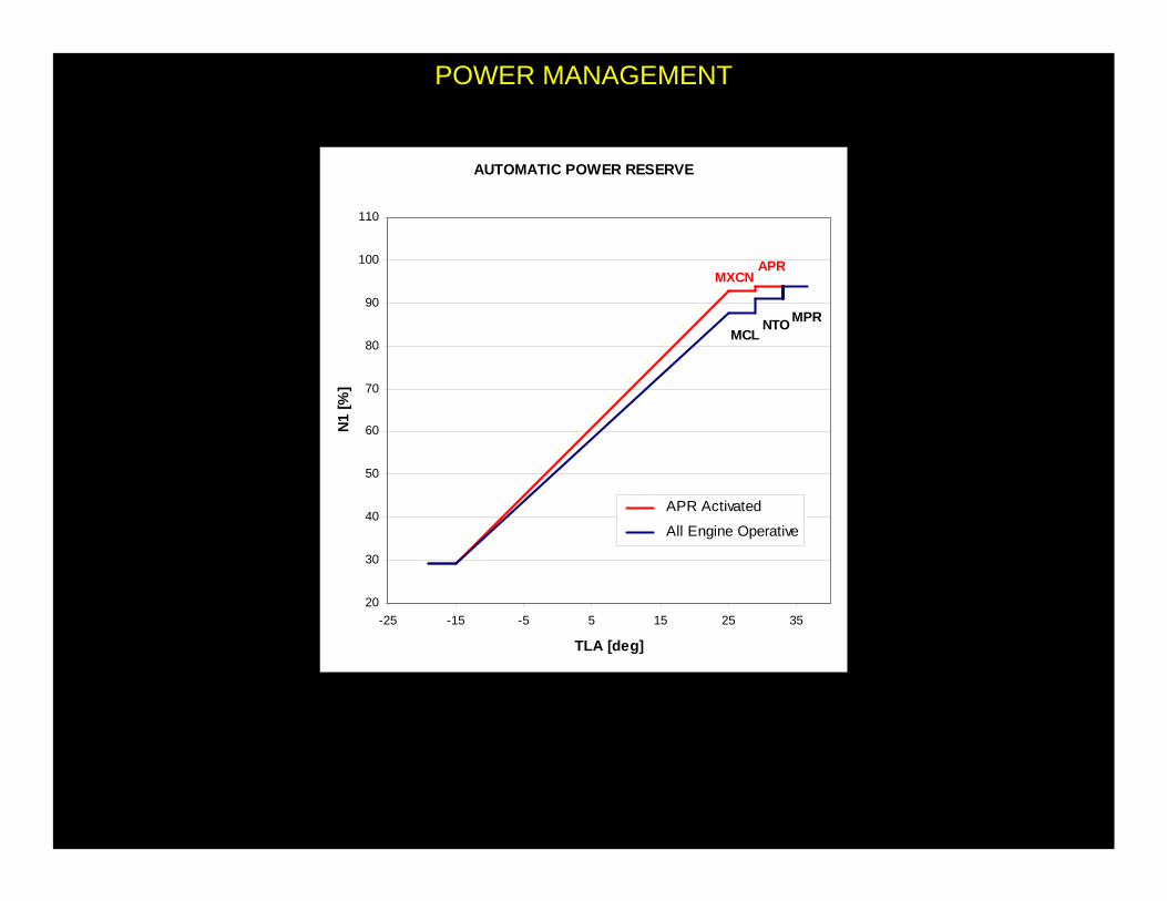
POWER MANAGEMENT
AUTOMATIC POWER RESERVE
20
30
40
50
60
70
80
90
100
110
-25 -15 -5 5 15 25 35
TLA [deg]
N1
[%]
APR Activated
All Engine Operative
MXCNAPR
MCLNTOMPR

POWER MANAGEMENT
MPR - Manual Power Reserve
• APR thrust can be manually selected by
advancing throttles up to MPR flat. This sets a
manual OEI latch that activate APR
• Once MPR flat is reached, retarding throttle to
NTO flat will still provide APR thrust. MCL detent
will provide MXCN thrust as well.
• OEI latch is cleared by further retarding throttles
below MCL flat
MANUAL POWER RESERVE
20
30
40
50
60
70
80
90
100
110
-25 -15 -5 5 15 25 35
TLA [deg]
N1
[%]
After MPR Selection
Before MPR Selection
MCL
NTO
MPR
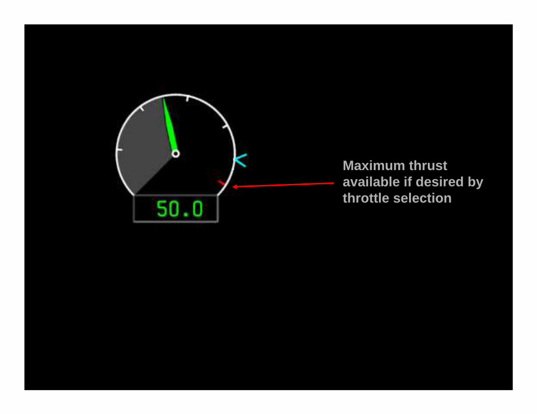
Maximum thrust available if desired by throttle selection
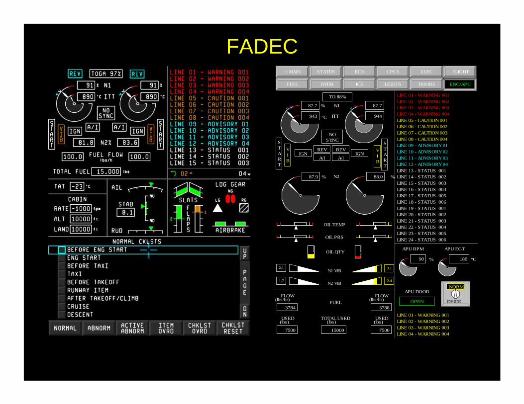
CPCS< MAIN STATUS ECS
ENG/APU
FLIGHT
LIGHTSFUEL HYDR ICE
ELEC
DOORS
APU DOOR
OPEN
OIL PRS
N2
USED(lbs)
7500
TOTAL USED(lbs)
15000
USED(lbs)
7500
FLOW(lbs/hr)
3784
FLOW(lbs/hr)
3788FUEL
OIL TEMP
OIL QTY
87.9 % 88.0 %
IGN IGN
TO 88%
REVREV
NOSYNC
VIB A/I A/I
START
START
VIB
87.7
943 °C
% N1
ITT
87.7
944
LINE 01 - WARNING 001LINE 02 - WARNING 002LINE 03 - WARNING 003LINE 04 - WARNING 004LINE 05 - CAUTION 001LINE 06 - CAUTION 002LINE 07 - CAUTION 003LINE 08 - CAUTION 004LINE 09 - ADVISORY 01LINE 10 - ADVISORY 02LINE 11 - ADVISORY 03LINE 12 - ADVISORY 04LINE 13 - STATUS 001LINE 14 - STATUS 002LINE 15 - STATUS 003LINE 16 - STATUS 004LINE 17 - STATUS 005LINE 18 - STATUS 006LINE 19 - STATUS 001LINE 20 - STATUS 002LINE 21 - STATUS 003LINE 22 - STATUS 004LINE 23 - STATUS 005LINE 24 - STATUS 006
%
APU RPM
90
APU EGT
180 °C
LINE 01 - WARNING 001LINE 02 - WARNING 002LINE 03 - WARNING 003LINE 04 - WARNING 004
DEICE
NORM
N1 VIB
N2 VIB1,7
3.1
2.4
2,1
FADEC

ENGINE STARTING
Starting Process:
1. Master Lever → ON2. Mode Selector → RUN3. Start Switch → ON
N20% 10%
IGN → ON
20%
FFL → ON
50%
Starter Cutout
GI
• Hot Start T45 > 810°C• Hung Start N2dot ↔ T45• No light off N2ind → T45
FADEC-observed Limitsbelow Idle on Ground:

POWER MANAGEMENT
N1 Synchronization
• This functionality provides N1 synchronization between RH and LH engine in order to accommodate
throttle stagger and reduce cabin noise
• When Synchronization is enabled the RH engine (Slave) N1 reference is biased to match LH engine
(Master) N1 reference.
• Maximum allowed bias is ± 2.36% relative to N1 reference corresponding to actual Slave TL position
• N1 Synchronization is enabled when:
– IDLE <= TLA < MCL detents
– APR not active
– No OEI indication
– Delta N1 reference between Master and Slave < 1.42%
• If delta N1 reference between Master and Slave becomes higher than ±2.36%, Slave engine N1 will
remain biased until Synchronization is disabled
• Slave engine control modes different from N1 reference (N2K, min PS3 etc.) will take priority over N1
synchronization reference

POWER MANAGEMENT
N2 Overspeed Protection
This system prevents engine core speed to overcome its overspeed threshold (102%)
• Two overspeed electronic circuit within FADEC, but independent from CPU receive N2 signal by
two different transducers.
• When both circuits detect N2 overspeed the FMU shut off solenoid is energized causing an engine
flame out. FADEC will detect flame out and turn ignition ON. When N2 falls below the overspeed
threshold, the FMU solenoid is de-energized to allow engine re-light
• The overspeed system latches fuel shut off if three N2 overspeeds are detected within 30 second
• System is tested at each ground starting and before flight and is activated at each shut down on
ground
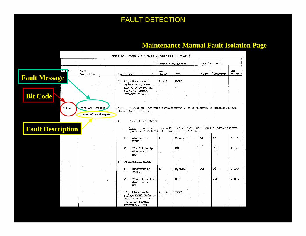
FAULT DETECTION
Maintenance Manual Fault Isolation Page
Bit Code
Fault Message
Fault Description


![FIGURE 12.1 Two variable process-control loops that interact. Curtis Johnson Process Control Instrumentation Technology, 8e] Copyright ©2006 by Pearson.](https://static.fdocuments.net/doc/165x107/5515176e550346a80c8b5e60/figure-121-two-variable-process-control-loops-that-interact-curtis-johnson-process-control-instrumentation-technology-8e-copyright-2006-by-pearson.jpg)

![FIGURE 7.1 Elements of the final control operation. Curtis Johnson Process Control Instrumentation Technology, 8e] Copyright ©2006 by Pearson Education,](https://static.fdocuments.net/doc/165x107/5513bdb35503463a298b47f4/figure-71-elements-of-the-final-control-operation-curtis-johnson-process-control-instrumentation-technology-8e-copyright-2006-by-pearson-education.jpg)