GEMINI™ 50/60 Hz Installation, Start-Up and Service ... · PDF fileManufacturer reserves...
44
Manufacturer reserves the right to discontinue, or change at any time, specifications or designs without notice and without incurring obligations. Catalog No. 04-53380005-01 Printed in U.S.A. Form 38A-21SI Pg 1 612 3-09 Replaces: 38A-17SI Installation, Start-Up and Service Instructions CONTENTS Page SAFETY CONSIDERATIONS . . . . . . . . . . . . . . . . . . . . . . 1 INSTALLATION . . . . . . . . . . . . . . . . . . . . . . . . . . . . . . . . 2-24 Rigging . . . . . . . . . . . . . . . . . . . . . . . . . . . . . . . . . . . . . . . . . . 2 Placing Unit . . . . . . . . . . . . . . . . . . . . . . . . . . . . . . . . . . . . . . 2 Mounting Unit . . . . . . . . . . . . . . . . . . . . . . . . . . . . . . . . . . . 14 Mounting Compressor . . . . . . . . . . . . . . . . . . . . . . . . . . 14 Refrigerant Piping Connections . . . . . . . . . . . . . . . . . 14 Liquid Solenoid Drop Refrigerant Control . . . . . . . 14 Filter Drier and Moisture Indicator. . . . . . . . . . . . . . . 14 Receiver . . . . . . . . . . . . . . . . . . . . . . . . . . . . . . . . . . . . . . . . 14 Piping Procedure. . . . . . . . . . . . . . . . . . . . . . . . . . . . . . . . 14 Power Supply . . . . . . . . . . . . . . . . . . . . . . . . . . . . . . . . . . . 17 Power Wiring . . . . . . . . . . . . . . . . . . . . . . . . . . . . . . . . . . . . 17 PRE-START-UP . . . . . . . . . . . . . . . . . . . . . . . . . . . . . . . 25-27 System Check . . . . . . . . . . . . . . . . . . . . . . . . . . . . . . . . . . . 25 Leak Test and Dehydration . . . . . . . . . . . . . . . . . . . . . . 25 Preliminary Charge. . . . . . . . . . . . . . . . . . . . . . . . . . . . . . 25 START-UP . . . . . . . . . . . . . . . . . . . . . . . . . . . . . . . . . . . . 28-31 38AKS Units . . . . . . . . . . . . . . . . . . . . . . . . . . . . . . . . . . . . 28 38AH Units . . . . . . . . . . . . . . . . . . . . . . . . . . . . . . . . . . . . . . 29 Sequence of Operation . . . . . . . . . . . . . . . . . . . . . . . . . . 30 SERVICE . . . . . . . . . . . . . . . . . . . . . . . . . . . . . . . . . . . . . 31-36 38AKS Units Access for Servicing . . . . . . . . . . . . . . 31 38AH Units Access for Servicing . . . . . . . . . . . . . . . . 33 Condenser Coil Maintenance and Cleaning Recommendation . . . . . . . . . . . . . . . . . . . . . . . . . . . . . 36 TROUBLESHOOTING. . . . . . . . . . . . . . . . . . . . . . . . . 36-40 START-UP CHECKLIST . . . . . . . . . . . . . . . . . . CL-1, CL-2 SAFETY CONSIDERATIONS Installing, starting up, and servicing air-conditioning equip- ment can be hazardous due to system pressures, electrical components, and equipment location (roofs, elevated struc- tures, etc.). Only trained, qualified installers and service mechanics should install, start-up, and service this equipment. Untrained personnel can perform basic maintenance func- tions such as cleaning coils. All other operations should be per- formed by trained service personnel. When working on the equipment, observe precautions in the literature and on tags, stickers, and labels attached to the equipment. Follow all safety codes. Wear safety glasses and work gloves. Keep quenching cloth and a fire extinguisher nearby when brazing. Use care in handling, rigging, and setting bulky equipment. WARNING Before installing or servicing system, always turn off main power to system and install lockout tag on disconnect. There may be more than one disconnect switch. Electrical shock can cause personal injury. WARNING DO NOT USE TORCH to remove any component. System contains oil and refrigerant under pressure. To remove a component, wear protective gloves and gog- gles and proceed as follows: a. Shut off electrical power to unit. b. Recover refrigerant to relieve all pressure from sys- tem using both high-pressure and low pressure ports. c. Traces of vapor should be displaced with nitrogen and the work area should be well ventilated. Refrig- erant in contact with an open flame produces toxic gases. d. Cut component connection tubing with tubing cutter and remove component from unit. Use a pan to catch any oil that may come out of the lines and as a gage for how much oil to add to the system. e. Carefully unsweat remaining tubing stubs when nec- essary. Oil can ignite when exposed to torch flame. Failure to follow these procedures may result in personal injury or death. CAUTION DO NOT re-use compressor oil or any oil that has been exposed to the atmosphere. Dispose of oil per local codes and regulations. DO NOT leave refrigerant system open to air any longer than the actual time required to service the equipment. Seal circuits being serviced and charge with dry nitrogen to prevent oil contamination when timely repairs cannot be completed. Failure to follow these proce- dures may result in damage to equipment. GEMINI™ 38AKS028-044 38AH024-034 Air-Cooled Condensing Units 50/60 Hz
Transcript of GEMINI™ 50/60 Hz Installation, Start-Up and Service ... · PDF fileManufacturer reserves...

Manufacturer reserves the right to discontinue, or change at any time, specifications or designs without notice and without incurring obligations.Catalog No. 04-53380005-01 Printed in U.S.A. Form 38A-21SI Pg 1 612 3-09 Replaces: 38A-17SI
Installation, Start-Up andService Instructions
CONTENTSPage
SAFETY CONSIDERATIONS . . . . . . . . . . . . . . . . . . . . . . 1INSTALLATION . . . . . . . . . . . . . . . . . . . . . . . . . . . . . . . . 2-24Rigging . . . . . . . . . . . . . . . . . . . . . . . . . . . . . . . . . . . . . . . . . . 2Placing Unit . . . . . . . . . . . . . . . . . . . . . . . . . . . . . . . . . . . . . . 2Mounting Unit . . . . . . . . . . . . . . . . . . . . . . . . . . . . . . . . . . . 14Mounting Compressor . . . . . . . . . . . . . . . . . . . . . . . . . . 14Refrigerant Piping Connections . . . . . . . . . . . . . . . . . 14Liquid Solenoid Drop Refrigerant Control . . . . . . . 14Filter Drier and Moisture Indicator. . . . . . . . . . . . . . . 14Receiver . . . . . . . . . . . . . . . . . . . . . . . . . . . . . . . . . . . . . . . . 14Piping Procedure. . . . . . . . . . . . . . . . . . . . . . . . . . . . . . . . 14Power Supply . . . . . . . . . . . . . . . . . . . . . . . . . . . . . . . . . . . 17Power Wiring . . . . . . . . . . . . . . . . . . . . . . . . . . . . . . . . . . . . 17PRE-START-UP . . . . . . . . . . . . . . . . . . . . . . . . . . . . . . . 25-27System Check. . . . . . . . . . . . . . . . . . . . . . . . . . . . . . . . . . . 25Leak Test and Dehydration . . . . . . . . . . . . . . . . . . . . . . 25Preliminary Charge. . . . . . . . . . . . . . . . . . . . . . . . . . . . . . 25START-UP . . . . . . . . . . . . . . . . . . . . . . . . . . . . . . . . . . . . 28-3138AKS Units . . . . . . . . . . . . . . . . . . . . . . . . . . . . . . . . . . . . 2838AH Units . . . . . . . . . . . . . . . . . . . . . . . . . . . . . . . . . . . . . . 29Sequence of Operation. . . . . . . . . . . . . . . . . . . . . . . . . . 30SERVICE . . . . . . . . . . . . . . . . . . . . . . . . . . . . . . . . . . . . . 31-3638AKS Units Access for Servicing . . . . . . . . . . . . . . 3138AH Units Access for Servicing . . . . . . . . . . . . . . . . 33Condenser Coil Maintenance and Cleaning
Recommendation . . . . . . . . . . . . . . . . . . . . . . . . . . . . . 36TROUBLESHOOTING. . . . . . . . . . . . . . . . . . . . . . . . . 36-40START-UP CHECKLIST . . . . . . . . . . . . . . . . . . CL-1, CL-2
SAFETY CONSIDERATIONS Installing, starting up, and servicing air-conditioning equip-
ment can be hazardous due to system pressures, electricalcomponents, and equipment location (roofs, elevated struc-tures, etc.).
Only trained, qualified installers and service mechanicsshould install, start-up, and service this equipment.
Untrained personnel can perform basic maintenance func-tions such as cleaning coils. All other operations should be per-formed by trained service personnel.
When working on the equipment, observe precautions inthe literature and on tags, stickers, and labels attached to theequipment.
Follow all safety codes. Wear safety glasses and workgloves. Keep quenching cloth and a fire extinguisher nearbywhen brazing. Use care in handling, rigging, and setting bulkyequipment.
WARNING
Before installing or servicing system, always turn off mainpower to system and install lockout tag on disconnect.There may be more than one disconnect switch. Electricalshock can cause personal injury.
WARNING
DO NOT USE TORCH to remove any component. Systemcontains oil and refrigerant under pressure. To remove a component, wear protective gloves and gog-gles and proceed as follows:a. Shut off electrical power to unit.b. Recover refrigerant to relieve all pressure from sys-
tem using both high-pressure and low pressure ports.c. Traces of vapor should be displaced with nitrogen
and the work area should be well ventilated. Refrig-erant in contact with an open flame produces toxicgases.
d. Cut component connection tubing with tubing cutterand remove component from unit. Use a pan to catchany oil that may come out of the lines and as a gagefor how much oil to add to the system.
e. Carefully unsweat remaining tubing stubs when nec-essary. Oil can ignite when exposed to torch flame.
Failure to follow these procedures may result in personalinjury or death.
CAUTION
DO NOT re-use compressor oil or any oil that has beenexposed to the atmosphere. Dispose of oil per local codesand regulations. DO NOT leave refrigerant system open toair any longer than the actual time required to service theequipment. Seal circuits being serviced and charge withdry nitrogen to prevent oil contamination when timelyrepairs cannot be completed. Failure to follow these proce-dures may result in damage to equipment.
GEMINI™38AKS028-044
38AH024-034Air-Cooled Condensing Units
50/60 Hz

2
INSTALLATION
Rigging — The preferred method of rigging is overheadrigging with spreader bars above the unit. Use 2-in. (50-mm)OD pipe or hooks in lifting holes. Rig with 4 cables andspreader bars. See Fig. 1.
NOTE: All panels must be in place when rigging. See rigginglabel on unit for details concerning shipping weights, distancebetween lifting holes, center of gravity, and spreader bardimensions.
If overhead rigging is not possible, place condensing uniton skid or pad for rolling or dragging. When rolling, use a min-imum of 3 rollers. When dragging, pull the pad. Do not applyforce to the unit. When in final position, raise from above to liftunit off pad.
Placing Unit — There must be 4 ft (1200 mm) of spacefor service and for unrestricted airflow on all sides of unit, anda minimum of 8 ft (2440 mm) clear air space above unit. Formultiple units, allow 8 ft (2440 mm) separation between unitsfor airflow and service. See Tables 1A-4B for physical data andFig. 2-4 for unit dimensions.
CAUTION
All panels must be in place when rigging. Do not forkliftunits if no skid is supplied. If unit has skid, forklift fromsides only. Failure to follow these requirements could resultin personal injury or equipment damage.
NOTES:1. Use 2-in. (50-mm) OD pipe or hooks in lifting holes. 2. Rig with 4 cables and spread with two ‘D’ long and two ‘A’ long
2 x 4 in. (50 x 100 mm) bars or equal.3. Run the rigging cables to a central suspension point so that the
angle from the horizontal is not less than 45 degrees.4. Shipping weights include skid.
UNITMAX SHIPPING
WEIGHTLIFTING HOLES CENTER OF GRAVITY DISTANCE BETWEEN
RIGGING CABLESA B C D
lb kg in. mm in. mm in. mm in. mm
38AKS028 1924 872 81 2057 43.0 1091 28.0 711 73.5 1867034 2115 960 81 2057 43.0 1092 28.0 711 73.5 1867044 2797 1207 127 3225 49.0 1245 30.5 775 73.5 1867
38AH
024 2240 1018
81 2057
40.0 1016
32.8 832 73.5 1867
024C 2403 1092 43.0 1092028 2300 1045 39.3 997028C 2463 1120 42.3 1073034 2360 1073 41.0 1041034C 2577 1171 44.0 1118
38AKS UNIT 38AH UNIT
Fig. 1 — Rigging with Spreader Bars (Field Supplied)

3
2'-4
"C
ENTE
RO
FG
RAV
ITY
CE
NTE
R O
F G
RAV
ITY
CLE
AR
AN
CE
TO
WA
LL O
R N
EX
T U
NIT
ACC
ES
S P
AN
EL
5'-8
"
CLE
AR
AN
CE
TO
WA
LL O
R N
EX
T U
NIT
2 1/
8"
WO
RK
ING
CLE
AR
AN
CE
PE
R N
EC
110-
16
4'-0
"
ACC
ESS
PAN
ELAC
CE
SS
PA
NE
L
ACC
ES
S P
AN
EL
ACC
ESS
DO
OR
HIN
GED
LIQ
UID
LIN
E C
ON
NE
CTI
ON
7/8"
O.D
.
SU
CTI
ON
LIN
E C
ON
NE
CTI
ON
1 5/
8" O
.D. (
028)
2 1/
8" O
.D. (
034)
MTG
. HO
LES
HIN
GE
D A
CC
ES
S D
OO
R
[63.
5]2
1/2"
DIA
.LI
FTIN
G
3/4"
DIA
.
[22.
2]
[63.
5-92
.1]
FIE
LD P
OW
ER
FIE
LD C
ON
TRO
L
2 1/
2"-3
5/8
" DIA
.
EN
TRY
& L
IFTI
NG
7/8"
DIA
. (2)
PO
WE
R E
NTR
Y
(TY
P 4
PLA
CE
S)
MO
UN
TIN
G H
OLE
S
[19.
1]
AIR
FLO
W T
HR
UC
ON
DE
NS
ER
[22.
2] 7
/8" D
IA.
[63.
5-92
.1] 2
1/2
"-3
5/8"
DIA
.
FIE
LD C
ON
TRO
L C
IRC
UIT
WIR
ING
FIE
LD M
AIN
PO
WE
R S
UP
PLY
CO
NTR
OL
BO
X
FOR
K T
RU
CK
LIFT
PO
CK
ETS
FOR
K T
RU
CK
LIFT
PO
CK
ETS
[22.
2]7/
8" D
IA.
V.A.
VP
OW
ER
EN
TRY
ACC
ES
S D
OO
R
BO
TH S
IDE
S
[711
]
[109
2] 3
'-7"
[121
9] 4
'-0"
[172
6]
[121
9] 4
'-0"
[54]
[121
9]
1413
[4'-7
5/8
"]
[81]
3 3/
16"
[113
8]3'
-8 1
3/16
"
[80]
3 1/
8"
[142
]
[324
7]10
'-7 1
3/16
"
[766
]2'
-6 5
/32"
[100
9]3'
-3 3
/4"
[208
]
[766
]2'
-6 1
/8"
[180
]7
1/16
"
[806
]
[241
][3
44]
[188
0]6'
-2"
[346
]1'
-1 5
/8"
[61]
2 7/
16"
[161
9]5'
-3 3
/4"
[235
]9
1/4"
[174
2]5'
-8 9
/16"
[131
5]4'
-3 3
/4"
[100
]3
15/1
6"
[40]
1 9/
16"
[205
7]6'
-9"
EN
D V
IEW
SID
E V
IEW
TO
P V
IEW
CO
MP
R S
EC
TIO
N
FA
N N
o. 1
FA
N N
o. 2
5 19
/32"
8 3/
16"
2'-7
3/4
"
9 1/
2"1'
-1 9
/16"
a38-7048N
OT
ES
:1.
The
re m
ust
be 4
ft
[122
0 m
m]
for
serv
ice
and
for
unre
stric
ted
airf
low
on
all s
ides
of u
nit.
2.T
here
mus
t be
min
imum
8 ft
[244
0 m
m] c
lear
air
spac
e ab
ove
unit.
3.T
he a
ppro
xim
ate
oper
atin
g w
eigh
t of t
he u
nit i
s:
NO
TE
: A
“C
” in
m
odel
nu
mbe
r in
dica
tes
unit
has
optio
nal
fact
ory-
inst
alle
d co
pper
-fin
coi
l.4.
Dim
ensi
ons
in [
] are
mill
imet
ers.
AP
PR
OX
IMA
TE
OP
ER
AT
ING
WE
IGH
T*
AT
SU
PP
OR
T P
OIN
TS
— L
B (
KG
)*
*Sta
ndar
d co
pper
tube
alu
min
um-f
in c
oil.
UN
IT38
AK
SW
EIG
HT
(lb
)W
EIG
HT
(kg
)02
816
5074
802
8C18
0481
803
418
0381
803
4C20
0991
1
UN
IT38
AK
S“1
”“2
”“3
”“4
”TO
TAL
028
418
(189
.6)
626
(284
.0)
242
(109
.8)
364
(165
.1)
1650
(748
.4)
034
459
(208
.2)
673
(305
.3)
272
(123
.4)
399
(181
.0)
1803
(817
.8)
Fig
. 2 —
38A
KS
028,
034
Un
it D
imen
sio
ns
“1“
“2“
“3““4“

4
2'-6
1/2
"C
ENTE
RO
FG
RAV
ITY
CE
NTE
R O
F G
RAV
ITY
CLE
AR
AN
CE
TO
WA
LL O
R N
EX
T U
NIT
ACC
ES
S P
AN
EL
CLE
AR
AN
CE
TO
WA
LL O
R N
EX
T U
NIT
5'-8
"
2 1/
8"
WO
RK
ING
CLE
AR
AN
CE
PE
R N
EC
110-
16
4'-0
"
ACC
ES
S P
AN
EL
ACC
ES
S P
AN
EL
ACC
ESS
PAN
ELH
ING
ED
AC
CE
SS
DO
OR
ACC
ESS
DO
OR
HIN
GED
LIQ
UID
LIN
EC
ON
NE
CTI
ON
7/8"
O.D
.
SU
CTI
ON
LIN
EC
ON
NE
CTI
ON
2 1/
8" O
.D.CO
NTR
OL
BO
X
[63.
5]2
1/2"
DIA
.LI
FTIN
G
3/4"
DIA
.
[22.
2][6
3.5-
92.1
]
FIE
LD P
OW
ER
FIE
LD C
ON
TRO
L
2 1/
2"-3
5/8
" DIA
.
EN
TRY
& L
IFTI
NG
7/8"
DIA
. (2)
PO
WE
R E
NTR
Y
(TY
P 4
PLA
CE
S)
MO
UN
TIN
G H
OLE
S
[19.
1]
AIR
FLO
W T
HR
UC
ON
DE
NS
ER
[22.
2] 7
/8" D
IA.
[63.
5-92
.1] 2
1/2
"-3
5/8"
DIA
.
FIE
LD C
ON
TRO
L C
IRC
UIT
WIR
ING
FIE
LD M
AIN
PO
WE
R S
UP
PLY
MTG
. HO
LES
FOR
K T
RU
CK
LIFT
PO
CK
ETS
FOR
K T
RU
CK
LIFT
PO
CK
ETS
ACC
ES
S D
OO
R
BO
TH S
IDE
S
[775
]
[124
5] 4
'-1"
[121
9] 4
'-0"
[121
9] 4
'-0"
[172
6]
[54]
[121
9]
1413
[4'-7
5/8
"]
[442
4]
14'-6
1/8
"
[80]
3 1/
8"
[142
]
[766
]2'
-6 5
/32"
[81]
3 3/
16"
[113
8]3'
-8 1
3/16
"
[100
9]3'
-3 3
/4"
[208
]
[766
]
2'-6
1/8
"[1
80]
7 1/
16"
[131
5]4'
-3 3
/4"
[806
]2'
-7 3
/4"
[241
]9
1/2"
1'-1
9/1
6"[4
52]
[346
]1'
-1 5
/8"
[266
7]8'
-9"
[322
5]10
'-7"
[61]
2 7/
16"
[161
9]5'
-3 3
/4"
[235
]9
1/4"
[174
2]
5'-8
9/1
6"
[100
]3
15/1
6"
[40]
1 9/
16"
EN
D V
IEW
SID
E V
IEW
TO
P V
IEW
CO
MP
R S
EC
TIO
N
FA
N N
o. 1
FA
N N
o. 2
FA
N N
o. 3
5 19
/32"
8 3/
16"
a38-7049
NO
TE
S:
1.T
here
mus
t be
4 ft
[122
0 m
m] f
or s
ervi
ce a
nd fo
r un
rest
ricte
dai
rflo
w o
n al
l sid
es o
f uni
t.2.
The
re m
ust b
e m
inim
um 8
ft [2
440
mm
] cle
ar a
ir sp
ace
abov
eun
it.3.
The
app
roxi
mat
e op
erat
ing
wei
ght o
f the
uni
t is:
NO
TE
: A
“C
” in
mod
el n
umbe
r in
dica
tes
unit
has
optio
nal
fact
ory-
inst
alle
d co
pper
-fin
coi
l.
AP
PR
OX
. OP
ER
. WT
*A
T L
IFT
ING
HO
LE
S —
LB
(K
G)*
*Sta
ndar
d co
pper
tube
alu
min
um-f
in c
oil.
UN
IT 3
8AK
SW
EIG
HT
(lb
)W
EIG
HT
(kg
)04
424
3711
0604
4C27
4512
46
UN
IT 3
8AK
S“1
”“2
”“3
”“4
”TO
TAL
044
720
(327
)90
0(4
09)
455
(207
)36
2(1
65)
2437
(110
6)
Fig
. 3 —
38A
KS
044
Un
it D
imen
sio
ns
“1“
“3“
“2“
“4“

5
a38-7055.eps
NO
TE
S:
1.T
here
mus
t be
4 f
t [1
220
mm
] fo
r se
rvic
e an
d fo
r un
rest
ricte
d ai
rflo
w o
n al
lsi
des
of u
nit.
2.T
here
mus
t be
min
imum
8 ft
[244
0 m
m] c
lear
air
spac
e ab
ove
unit.
3.“C
” in
the
pack
age
num
ber
indi
cate
s co
pper
coi
ls.
4.D
imen
sion
s in
[ ]
are
in m
illim
eter
s.5.
The
app
roxi
mat
e op
erat
ing
wei
ght o
f the
uni
t is
show
n be
low
.6.
Cer
tifie
d di
men
sion
al d
raw
ing
is a
vaila
ble
on r
eque
st.
UN
IT38
AH
CO
RN
ER
WE
IGH
T —
lb [
kg]
CE
NT
ER
OF
GR
AV
ITY
TOTA
LU
NIT
WT
lb [
kg]
“1”
“2”
“3”
“4”
A D
im.
in.
[mm
]
B D
im.
in.
[mm
]
024
631.
657
7.6
263.
128
7.7
40.0
0
32.7
5[8
32]
1760
[286
.5]
[262
.0]
[119
.3]
[130
.5]
[101
6][7
98.3
]
024C
666.
560
9.5
309.
033
7.9
43.0
019
23[3
02.3
][2
76.5
][1
40.2
][1
53.3
][1
092]
[872
.3]
028
658.
760
2.4
267.
029
1.9
39.2
518
20[2
98.8
][2
73.3
][1
21.1
][1
32.4
][9
97]
[825
.6]
028C
693.
063
3.8
313.
034
2.2
42.2
519
82[3
14.3
][2
87.5
][1
42.0
][1
55.2
][1
073]
[899
.0]
034
667.
061
0.0
288.
031
5.0
41.0
018
80[3
02.5
][2
76.7
][1
30.7
][1
42.9
][1
041]
[853
.0]
034C
718.
365
6.8
344.
837
7.0
44.0
020
97[3
25.8
][2
97.9
][1
56.4
][1
71.0
][1
117]
[951
.2]
Fig
. 4 —
38A
H02
4-03
4 U
nit
Dim
ensi
on
s

6
Table 1A — Physical Data — 38AKS028-044 Units — 60 Hz, English
*Unit is factory-supplied with nitrogen holding charge only.†Typical operating charge with 25 ft of interconnected piping. Operating charge is approximate for maximum system capacity.**Storage capacity is 80% full at liquid saturated temperature of 125 F.
UNIT 38AKS 028 034 044NOMINAL CAPACITY (tons) 25 30 40OPERATING WEIGHTS (lb)
Aluminum-Fin Coils (standard) 1650 1803 2437Copper-Fin Coils (optional) 1804 2009 2745
REFRIGERANT* R-22Operating Charge, Typical (lb)† 30.5 43.5 65.0
COMPRESSOR Reciprocating, Semi-HermeticQty...Model 1...06E9265 1...06E9275 1...06E9299Oil Charge (pt) 20 20 19No. Cylinders 6 6 6Speed (rpm) 1750Capacity Steps (%) 100, 66, 33
Unloader Setting (psig)Unloader No. 1 Load 76
Unload 58Unloader No. 2 Load 78
Unload 60Crankcase Heater Watts 180
CONDENSER FANS Propeller Type — Direct DriveQty...Rpm 2...1140 3...1140Diameter (in.) 30Nominal Hp 1.0Nominal Airflow (cfm total) 15,700 23,700Watts (total) 1490 1750 1520
CONDENSER COIL Enhanced Copper Tubes, Lanced Aluminum FinsRows...Fins/in. 2...19 3...17 3...17Face Area (sq ft total) 39.2 39.2 58.4Storage Capacity (lb)** 37.7 56.6 84.4
CONTROLSPressurestat Settings (psig)
High Open 426 ± 7Close 320 ± 20
Low Open 27 ± 3Close 44 ± 5
Oil Pressure SwitchOpen 6.2Close 9.0
FAN CYCLING CONTROLSOperating Pressure (psig)
No. 2 Fan, Close 255 ± 10Open 160 ± 10
PRESSURE RELIEFLocation Liquid and Suction LineTemperature (F) 210
PIPING CONNECTIONS (in. ODM)Suction 15/8 21/8 21/8Liquid 7/8Hot Gas 5/8

7
Table 1B — Physical Data — 38AKS028-044 Units — 60 Hz, SI
*Unit is factory supplied with nitrogen holding charge only.†Typical operating charge with 7.5 m of interconnected piping. Operating charge is approximate for maximum system capacity.**Storage capacity is 80% full at liquid saturated temperature of 51.7 C.
UNIT 38AKS 028 034 044NOMINAL CAPACITY (kW) 88 105 141OPERATING WEIGHT (kg)
Aluminum-Fin Coils (standard) 748 818 1106Copper-Fin Coils (optional) 818 911 1246
REFRIGERANT* R-22Operating Charge Typical (kg)† 14 20 29
COMPRESSOR Reciprocating, Semi HermeticQty...Model 1...06E9265 1...06E9275 1...06E9299Oil Charge (L) 9.4 9.4 9No. Cylinders 6Speed (r/s) 29Capacity Steps (%) 100,66,33
Unloader Settings (kPa)Unloader No. 1 Load 524
Unload 400Unloader No. 2 Load 538
Unload 414Crankcase Heater Watts 180
CONDENSER FANS Propeller Type-Direct DriveQty...r/s 2...29Diameter (mm) 2…762 3…762Nominal Hp 1 1Nominal Airflow (L/s) 7400 11,180Watts (total) 1490 1750 1520
CONDENSER COIL Enhanced Copper Tubes, Lanced Aluminum FinsRows….Fins/m. 2…748 3…670Face Area (sq. m total) 3.6 3.6 5.4Storage Capacity (kg)** 17.1 25.7 38.3
CONTROLSPressurestat Settings (kPa)
High Open 2937 ± 48Close 2206 ± 138
Low Open 186 ± 21Close 303 ± 34
Oil Pressure SwitchOpen 43Close 62
FAN CYCLING CONTROLSOperating Pressure (kPa)
No. 2 Fan, Close 1793 ± 103Open 1103 ± 69
PRESSURE RELIEFLocation Liquid and Suction LineTemperature (C) 98.9
PIPING CONNECTIONS (in. ODM)Suction 15/8 21/8 21/8Liquid 7/8Hot Gas 5/8
8
Table 2A — Physical Data — 38AH024-034 Units — 60 Hz, English
LEGEND
*Unit is factory supplied with nitrogen holding charge only.†Typical operating charge with 25 ft of interconnecting piping. Operating charge is approximate for maximum system capacity.**Standard unit — single suction pressure-actuated unloader on compressor no. 1.
††VAV FIOP — two electrically actuated unloaders on compressor no. 1.***Storage capacity is 80% full at liquid saturated temperature of 120 F.NOTE: Refer to Loading Sequence tables on page 31 for additional capacity step data.
UNIT 38AH024 028 034
Ckt 1 Ckt 2 Ckt 1 Ckt 2 Ckt 1 Ckt 2NOMINAL CAPACITY (tons) 20 25 30OPERATING WEIGHT (lb)
Aluminum-Fin Coil (standard) 1760 1820 1880Copper-Fin Coil (optional) 1923 1982 2097
REFRIGERANT* R-22Operating Charge, Typical (lb)† 20 20 20 20 25 25
COMPRESSOR Reciprocating Semi-Hermetic Qty...Model 1...06DH824 1...06DA824 1...06DH328 1...06DA328 1...06DH328 1...06DA537No. Cylinders 6 6 6 6 6 6Speed (rpm) 1750 1750 1750 1750 1750 1750Oil Charge Per Circuit (pt) 10Capacity Steps (%)
100 100 100 100 100 10067** — 67** — 67** —33†† — 33†† — 33†† —
Unloader Setting (psig) Factory InstalledLoad 76 — 76 — 76 —Unload 58 — 58 — 58 —
CONDENSER FANS Propeller Type — Direct DrivenQty...Rpm 2...1140Diameter (in.) 30Nominal Hp 1.0 1.0 1.0Nominal Airflow (cfm) 16,700 16,700 15,700Watts (total) 1550
CONDENSER COIL Enhanced Copper Tubes, Lanced Aluminum Fins Rows...Fins/in. 2...19 2...19 3...17Face Area (sq ft total) 39.20 39.20 39.20Storage Cap. (lb)*** 37.7 37.7 56.6
CONTROLSPressurestat Settings (psig)
High Open 426 ± 7Close 320 ± 20
Low Open 27 ± 3Close 44 ± 5
Oil Pressure Switch Manual ResetOpen 6.0Close 8.8
FAN CYCLING CONTROLSTemperature (F)
No. 2 Fan, Close 70 ± 3Open 60 ± 3
PRESSURE RELIEFLocation Liquid Line, Suction Line, CompressorTemperature (F) 210
PIPING CONNECTIONS (in. ODM)Suction 13/8Liquid 5/8Hot Gas 5/8
FIOP — Factory-Installed OptionVAV — Variable Air Volume

9
Table 2B — Physical Data — 38AH024-034 Units — 60 Hz, SI
*Unit is factory supplied with nitrogen holding charge only.†Typical operating charge with 7.5m of interconnected piping. Operating charge is approximate for maximum system capacity.**Standard unit with single pressure operated unloader on compressor No. 1.
††VAV FIOP with two electrically operated unloaders on compressor No. 1.***Storage capacity is 80% full at liquid saturated temperature of 48.8 C.
UNIT 38AH 024 028 034Ckt 1 Ckt 2 Ckt 1 Ckt 2 Ckt 1 Ckt 2
NOMINAL CAPACITY (kW) 70 88 105OPERATING WEIGHT (kg)
Aluminum-Fin Coils (standard) 798.3 825.6 853951.2Copper-Fin Coils (optional) 872.3 899
REFRIGERANT* R-22Operating Charge Typical (kg)† 9.1 9.1 9.1 9.1 11.4 11.4
COMPRESSOR Reciprocating, Semi HermeticQty...Model 1...06DH824 1...06DA824 1...06DH328 1...06DA328 1...06DH328 1...06DA537No. Cylinders 6 6 6Speed (r/s) 29 29 29Oil Charge Per Circuit (L) 4.7 4.7 4.7 4.7 4.7 4.7Capacity Steps (%)
100 100 100 100 100 10067** — 67** — 67** —33†† — 33†† — 33†† —
Unloader Settings (kPa) Factory InstalledLoad 524 — 524 — 524 —Unload 400 — 400 — 400 —
CONDENSER FANS Propeller Type - Direct DrivenQty...r/s 2...19Diameter (mm) 762
1.0Nominal HpNominal Airflow (L/s) 7882 7882 7410Watts (total) 1550
CONDENSER COIL Enhanced Copper Tubes, Lanced Aluminum FinsRows….Fins/m 2…748 2…748
3.63…670
Face Area (Sq. m total) 3.6 3.6Storage Capacity (kg)*** 17.4 17.4 26.0
CONTROLSPressurestat Settings (kPa)
High Open 2937 ± 48Close 2206 ± 138
Low Open 186 ± 21Close 303 ± 34
Oil Pressure Switch Manual ResetOpen 43Close 62
FAN CYCLING CONTROLSTemperature (C)
No. 2 Fan, Close 21 ± 1.5Open 15.5 ± 1.5
PRESSURE RELIEFLocation Liquid Line, Suction Line, CompressorTemperature (C) 100
PIPING CONNECTIONS (in. ODM)Suction 13/8Liquid 5/8Hot Gas 5/8

10
Table 3A — Physical Data — 38AKS028-044 Units — 50 Hz, English
*Unit is factory supplied with nitrogen holding charge only.†Typical operating charge with 25 ft of interconnecting piping. Operating charge is approximate for maximum system capacity.**Storage capacity is 80% full at liquid saturated temperature of 125 F.
UNIT 38AKS 028 034 044NOMINAL CAPACITY (tons) 23.4 26.7 35.8OPERATING WEIGHTS (lb)
Aluminum-Fin Coils (standard) 1650 1803 2437Copper-Fin Coils (optional) 1804 2009 2745
REFRIGERANT* R-22Operating Charge, Typical (lb)† 30.5 43.5 65.0
COMPRESSOR Reciprocating, Semi-HermeticQty...Model 1...06E9265 1...06E9275 1...06E9299Oil Charge (pt) 20 20 19No. Cylinders 6 6 6Speed (rpm) 1450Capacity Steps (%) 100, 66, 33Unloader Setting (psig)
Unloader No. 1 Load 76Unload 58
Unloader No. 2 Load 78Unload 60
Crankcase Heater Watts 180CONDENSER FANS Propeller Type — Direct Drive
Qty...(Rpm) 2...950 3...950Diameter (in.) 30Nominal Hp 1.0Nominal Airflow (cfm total) 15,700 23,700Watts (Total) 1490 1750 1520
CONDENSER COIL Enhanced Copper Tubes, Lanced Aluminum FinsRows...Fins/in. 2...19 3...17 3...17Face Area (sq ft total) 39.2 39.2 58.4Storage Capacity (lb)** 37.7 56.6 84.4
CONTROLSPressurestat Settings (psig)
High Open 426 ± 7Close 320 ± 20
Low Open 27 ± 3Close 44 ± 5
Oil Pressure Switch Open 6.2Close 9.0
FAN CYCLING CONTROLSOperating Pressure (psig)
No. 2 Fan, Close 255 ± 10Open 160 ± 10
PRESSURE RELIEFLocation Liquid and Suction LineTemperature (F) 210
PIPING CONNECTIONS (in. ODM)Suction 15/8 21/8 21/8Liquid 7/8Hot Gas 5/8

11
Table 3B — Physical Data — 38AKS028-044 Units — 50 Hz, SI
*Unit is factory supplied with nitrogen holding charge only.†Typical operating charge with 7.6 m of interconnecting piping. Operating charge is approximate for maximum system capacity.**Storage capacity is 80% full at liquid saturated temperature of 51.7 C.
UNIT 38AKS 028 034 044NOMINAL CAPACITY (kW) 82.8 94.5 127.0OPERATING WEIGHTS (kg)
Aluminum-Fin Coils (standard) 748 818 1106Copper-Fin Coils (optional) 818 911 1246
REFRIGERANT* R-22Operating Charge, Typical (kg)† 13.8 19.7 29.5
COMPRESSOR Reciprocating, Semi-HermeticQty...Model 1...06E9265 1...06E9275 1...06E9299Oil Charge (L) 8.99 8.99 9.46No. Cylinders 6 6 6Speed (r/s) 24.2Capacity Steps (%) 100, 66, 33Unloader Settings (kPa)
Unloader No. 1 Load 524Unload 400
Unloader No. 2 Load 538Unload 414
Crankcase Heater Watts 180CONDENSER FANS Propeller Type — Direct Drive
Qty...r/s 2...15.8 3...15.8Diameter (mm) 762Nominal Hp 1.0Nominal Airflow (L/s total) 7400 11,180Watts (Total) 1490 1750 1520
CONDENSER COIL Enhanced Copper Tubes, Lanced Aluminum FinsRows...Fins/m 2...748 3...670 3...670Face Area (sq m total) 3.64 3.64 5.43Storage Capacity (kg)** 17.1 25.7 38.3
CONTROLSPressurestat Settings (kPa)
High Open 2937 ± 48Close 2206 ± 138
Low Open 186 ± 21Close 303 ± 34
Oil Pressure Switch Open 43Close 62
FAN CYCLING CONTROLSOperating Pressure (kPa)
No. 2 Fan, Close 1758 ± 69Open 1103 ± 69
PRESSURE RELIEFLocation Liquid and Suction LineTemperature (C) 98.9
PIPING CONNECTIONS (in. ODM)Suction 15/8 21/8 21/8Liquid 7/8Hot Gas 5/8

12
Table 4A — Physical Data — 38AH024-034 Units — 50 Hz, English
LEGEND
*Unit is factory supplied with nitrogen holding charge only.†Typical operating charge with 25 ft of interconnecting piping. Oper-
ating charge is approximate for maximum system capacity.**Standard unit — single pressure-actuated suction unloader on
compressor no. 1.
††VAV FIOP — double electrically actuated unloaders on compres-sor no. 1.
***Storage capacity is 80% full at liquid saturated temperature of120 F.
NOTE: Refer to Loading Sequence tables on page 31 for additionalcapacity step data.
UNIT 38AH024 028 034
Circuit 1 Circuit 2 Circuit 1 Circuit 2 Circuit 1 Circuit 2NOMINAL CAPACITY (Tons) 18 21 25OPERATING WEIGHT (lb)
Aluminum-Fin Coil (standard) 1760 1820 1880Copper-Fin Coil (optional) 1923 1982 2097
REFRIGERANT* R-22Operating Charge, Typical (lb)† 20 20 20 20 25 25
COMPRESSOR Reciprocating Semi-HermeticQty...Model 1...06DH824 1...06DA824 1...06DH328 1...06DA328 1...06DH328 1...06DA537No. Cylinders 6 6 6 6 6 6Speed (rpm) 1450 1450 1450 1450 1450 1450Oil Charge Per Circuit (Pt) 10Capacity Steps %
100 100 100 100 100 10067** — 67** — 67** —33†† — 33†† — 33†† —
Unloader Setting (psig) Factory InstalledLoad 76 — 76 — 76 —Unload 58 — 58 — 58 —
CONDENSER FANS Propeller Type — Direct DrivenQty...Rpm 2...950Diameter (in.) 30 30 30Nominal Hp 1.0 1.0 1.0Nominal Airflow (cfm) 16,700 16,700 15,700Watts (total) 3100
CONDENSER COIL Enhanced Copper Tubes, Aluminum Lanced FinRows...Fins/in. 2...19 2...19 3...17Face Area (sq ft total) 39.20 39.20 39.20Storage Capacity (lb)*** 37.7 37.7 56.6
CONTROLSPressurestat Settings (psig)
High Open 426 7Close 320 20
Low Open 27 3Close 44 5
Oil Pressure Switch Manual ResetCutout 6.0Cut-in 8.8
FAN CYCLING CONTROLSTemperature (F)
No. 2 Fan, Close 70 3Open 60 3
PRESSURE RELIEFLocation Liquid Line, Suction Line, CompressorTemperature (F) 210
PIPING CONNECTIONS (in. ODM)Suction 13/8Liquid 5/8Hot Gas 5/8
FIOP — Factory-Installed OptionVAV — Variable Air Volume

13
Table 4B — Physical Data — 38AH024-034 Units — 50 Hz, SI
LEGEND
*Unit is factory supplied with nitrogen holding charge only.†Typical operating charge with 7.6 m of interconnecting piping.Operating charge is approximate for maximum system capacity.
**Standard unit — single pressure-actuated suction unloader oncompressor no. 1.
††VAV FIOP — double electrically actuated unloaders on compres-sor no. 1.
***Storage capacity is 80% full at liquid saturated temperature of120 F.
NOTE: Refer to Loading Sequence tables on page 31 for additionalcapacity step data.
UNIT 38AH024 028 034
Circuit 1 Circuit 2 Circuit 1 Circuit 2 Circuit 1 Circuit 2NOMINAL CAPACITY (kW) 63 73 87OPERATING WEIGHT (kg)
Aluminum-Fin Coil (standard) 798.3 825.6 853.0Copper-Fin Coil (optional) 872.3 899.0 951.2
REFRIGERANT* R-22Operating Charge, Typical (kg)† 9.10 9.10 9.10 9.10 11.40 11.40
COMPRESSOR Reciprocating Semi-HermeticQty...Model 1...06DH824 1...06DA824 1...06DH328 1...06DA328 1...06DH328 1...06DA537No. Cylinders 6 6 6 6 6 6Speed (r/s) 24.3 24.3 24.3 24.3 24.3 24.3Oil Charge Per Circuit (L) 4.73Capacity Steps (%)
100 100 100 100 100 10067** — 67** — 67** —33†† — 33†† — 33†† —
Unloader Setting (kPa) Factory InstalledLoad 524 — 524 — 524 —Unload 400 — 400 — 400 —
CONDENSER FANS Propeller Type — Direct DrivenQty... r/s 2...16Diameter (mm) 762 762 762Nominal Hp 1.0 1.0 1.0Nominal Airflow (L/s) 7870 7870 7400Watts (total) 3100
CONDENSER COIL Enhanced Copper Tubes, Aluminum Lanced FinRows...Fins/m 2...748 2...748 3...670Face Area (sq m total) 3.64 3.64 3.64Storage Capacity (kg)*** 17.4 17.4 26.0
CONTROLSPressurestat Settings (kPa)
High Open 2937 48Close 2206 138
Low Open 186 21Close 303 34
Oil Pressure Switch Manual ResetCutout 41.4Cut-in 60.7
FAN CYCLING CONTROLSTemperature (C)
No. 2 Fan, Close 21.1 1.6Open 15.6 1.6
PRESSURE RELIEFLocation Liquid Line, Suction Line, CompressorTemperature (C) 99
PIPING CONNECTIONS (in. ODM)Suction 13/8Liquid 5/8Hot Gas 5/8
FIOP — Factory-Installed OptionVAV — Variable Air Volume

14
Mounting Unit — When unit is in proper location, use ofmounting holes in base rails is recommended for securingunit to supporting structure, or for mounting unit on vibrationisolators if required. See Fig. 5. Fasteners for mounting unit arefield supplied. Be sure to mount unit level to ensure proper oilreturn to compressors.
Mounting Compressor — As shipped, the compressoris held down by 4 bolts. After unit is installed, loosen each boltuntil the snubber washer can be moved with finger pressure.See Fig. 6.
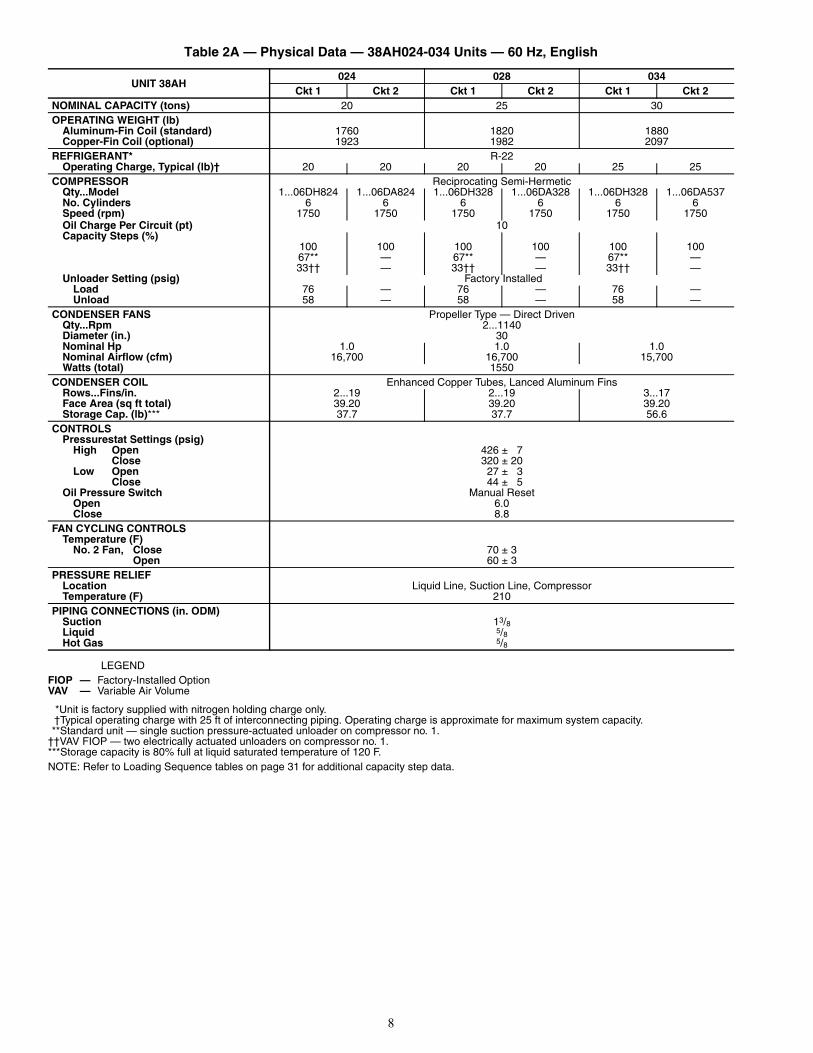
Refrigerant Piping Connections — Line sizes de-pend on length of piping required between condensing unit andevaporator. See Tables 5A-10B. It is important to consider liquidlift and compressor oil return. Refer to Part 3 of Carrier SystemDesign Manual for line sizing information, and Fig. 7-9 for rec-ommended piping details. Do NOT bury refrigerant piping.
Liquid Solenoid Drop Refrigerant Control —All units are factory wired to operate on solenoid drop refriger-ant control. A field-supplied liquid line solenoid valve (LLSV)must be installed in the liquid line ahead of the indoor coil on38AH units. See Fig. 8. Wires from solenoid valve need to be inconduit as coil voltage is 115-v.NOTE: Failure to properly install liquid line solenoid at theindoor unit as described, without Carrier authorization, mayVOID warranty.
The LLSV is shipped with the 38AKS units and field-supplied for 38AH units.
Filter Drier and Moisture Indicator — Every unitshould have a filter drier and a sight glass (moisture indicator)field installed. Select the filter drier for maximum unit capacityand minimum pressure drop. Figures 7 and 8 show recom-mended locations of filter drier(s) and sight glass(es). Com-plete the refrigerant piping from the evaporator to thecondenser before opening the liquid and suction lines at thecondensing unit.
Receiver — No receiver is provided with the unit; it is rec-ommended that one not be used.
Piping Procedure — Do not remove run-around pipefrom suction and liquid line stubs until piping connections areready to be made. Relieve the factory-supplied nitrogencharge. Remove the run-around loop by cutting the liquid lineand suction line as close to the loop as possible.
Pass nitrogen or other inert gas through piping while braz-ing, to prevent formation of copper oxide. Install field-suppliedthermostatic expansion valve (TXV) in liquid line ahead ofeach evaporator section.
CAUTION
System is factory charged with nitrogen. Relieve pressurebefore connecting pipe. Failure to do so could result in per-sonal injury.
Fig. 6 — Mounting Compressor(Typical 38AH Unit Shown)
Fig. 5 — Mounting on Vibration Isolator
LEGEND
NOTES:1. Lower section is first on and last off.2. For more complete piping information, refer to Carrier System
Design Manual, Part 3, or E20-II® refrigerant piping com-puter program.
Fig. 7 — Suction Line Piping to Unit with2-Section Coil Split (Typical 38AH Unit Shown)
TXV — Thermostatic Expansion Valve
15
Table 5A — Refrigerant Pipe Sizes,Single Suction Risers —
38AKS028-044, 60 Hz Units
LEGEND
*Requires a double suction riser, if evaporator is below condensing unit. SeeTable 5B.NOTE: Liquid and suction line sizes are OD (in.)
Table 5B — Refrigerant Pipe Sizes,Double Suction Risers —
38AKS028-044, 60 Hz Units
NOTE: For A, B, and C dimensions refer to Fig. 9.
Table 6 — Maximum Liquid Lift — 38AKS028-044
Table 7A — Refrigerant Pipe Sizes,Single Suction Risers —
38AH024-034, 60 Hz Units
LEGEND
*Double suction riser required if evaporator is below condensing unit and 2unloaders are used on that circuit.
†Double suction riser required if evaporator is below condensing unit andcompressor is equipped with 2 unloaders. Note the only time circuit no. 2may be equipped with 2 unloaders is if it is serving its own air handler andthe unit does not require low ambient operation (Motormaster® III control).
**Double suction riser required if evaporator is below condensing unit andcompressor has one or more unloader(s).
NOTES:1. All line sizes are inches OD.2. Standard unit comes with one pressure-operated unloader on circuit
no. 1. If unit serves one air handler, an additional unloader may be fieldinstalled on circuit no. 1 compressor only. If the unit serves 2 separate airhandlers and low ambient operation is required (Motormaster III control),each circuit’s compressor may only be equipped with one unloader.
Table 7B — Refrigerant Pipe Sizes,Double Suction Risers —38AH024-034, 60 Hz Units
NOTE: For A, B, and C dimensions refer to Fig. 9.
Table 8 — Maximum Liquid Lift — 38AH024-034
UNIT38AKS
LENGTH OF INTERCONNECTING PIPING, Ft (m)16-25
(4.9-7.6)26-50
(7.9-15.2)51-75
(15.5-22.8)76-100
(23.2-30.5)101-200
(30.8-60.9)L S L S L S L S L S
028 7/8 15/8 7/8 21/8* 7/8 21/8* 7/8 21/8* 7/8 21/8*034 7/8 21/8 7/8 21/8 7/8 21/8 11/8 21/8 11/8 25/8*044 7/8 21/8 7/8 21/8 11/8 25/8* 11/8 25/8* 11/8 25/8*
L — Liquid LineS — Suction Line
UNIT38AKS
LENGTH OF INTERCONNECTING PIPING, Ft (m)26-50
(7.9-15.2)51-75
(15.5-22.8)76-100
(23.2-30.5)101-200
(30.8-60.9)A B C A B C A B C A B C
028 13/8 15/8 21/8 13/8 15/8 21/8 13/8 15/8 21/8 13/8 15/8 21/8034 — — — — — — — — — 15/8 21/8 25/8044 — — — 15/8 21/8 25/8 15/8 21/8 25/8 15/8 21/8 25/8
UNIT 38AKS MAXIMUM LIQUID LIFTPER CIRCUIT — Ft (m)
028 76 (23.2)034 67 (20.4)044 76 (23.2)
UNIT 38AH
LENGTH OF INTERCONNECTING PIPING,FOR EACH CIRCUIT, Ft (m)
0-25(0-7.6)
25-50(7.9-15.2)
50-75(15.5-22.8)
75-100(23.2-30.5)
100-200(30.8-60.9)
L S L S L S L S L S024 Ckt 1 1/2 11/8 5/8 13/8 5/8 13/8 5/8 15/8* 7/8 15/8*
Ckt 2 1/2 11/8 5/8 13/8 5/8 13/8 5/8 15/8† 7/8 15/8†028 Ckt 1 1/2 11/8 5/8 13/8 5/8 13/8 7/8 15/8* 7/8 21/8**
Ckt 2 1/2 11/8 5/8 13/8 5/8 13/8 7/8 15/8† 7/8 21/8**034 Ckt 1 1/2 11/8 5/8 13/8 5/8 15/8* 7/8 15/8* 7/8 21/8**
Ckt 2 1/2 13/8 5/8 15/8 7/8 15/8 7/8 15/8 7/8 21/8†
L — Liquid LineS — Suction Line
UNIT 38AH
LENGTH OF INTERCONNECTING PIPING, Ft (m)50-75
(15.5-22.8)75-100
(23.2-30.5)100-200
(30.8-60.9)A B C A B C A B C
024 Ckt 1 — — — 11/8 13/8 15/8 11/8 13/8 15/8
Ckt 2 — — — 11/8 13/8 15/8 13/8 13/8 15/8
028 Ckt 1 — — — 11/8 13/8 15/8 13/8 15/8 21/8
Ckt 2 — — — 11/8 13/8 15/8 13/8 15/8 21/8
034 Ckt 1 11/8 13/8 15/8 11/8 13/8 15/8 13/8 15/8 21/8
Ckt 2 — — — — — — 13/8 15/8 21/8
UNIT 38AH MAXIMUM LIQUID LIFTPER CIRCUIT — Ft (m)
024 76 (23.2)028 73 (22.3)034 100 (30.5)
SUCTION LINE PIPING
LEGEND
Suction Riser Without Trap
Suction Riser With Trap
Horizontal Suction Line to Condensing Unit
Short Vertical Riser:38AKS028 — 15/8 in. OD38AKS034, 044 — 21/8 in. OD38AH — Diameter to be the same asRiser A.
A
B
C
D
Fig. 9 — Suction Line Piping,38AKS,AH Units
LEGEND
Fig. 8 — Liquid Line Solenoid Valve, Filter Drier(s),and Sight Glass Locations(Typical 38AH Unit Shown)
TXV — Thermostatic Expansion Valve
a38-2671tf

16
Table 9A — Refrigerant Pipe Sizes, Single Suction Risers — 38AKS028-044, 50 Hz Units
LEGEND *If condensing unit is above air handler, a double suction riser isrequired. See Table 9B below for sizing.
Table 9B — Refrigerant Pipe Sizes, Double Suction Risers —38AKS028-044, 50 Hz Units
NOTE: For A, B, and C dimensions, refer to Fig. 9.
Table 10A — Refrigerant Pipe Sizes, Single Suction Risers —38AH024-034, 50 Hz Units
LEGEND
*Double suction riser required if evaporator is below condensingunit and 2 unloaders are used on that circuit.
†Double suction riser required if evaporator is below condensing unitand compressor is equipped with 2 unloaders. Note the only timecircuit no. 2 may be equipped with 2 unloaders is if it is serving itsown air handler and the unit does not require low ambient opera-tion (Motormaster® III control).
NOTES:1. All line sizes are inches OD.2. Standard unit comes with one pressure-operated unloader on
circuit no. 1. If unit serves one air handler, an additionalunloader may be field installed on circuit no. 1 compressor only.If the unit serves 2 separate air handlers and low ambient oper-ation is required (Motormaster III control), each circuit’s com-pressor may only be equipped with one unloader.
Table 10B — Refrigerant Pipe Sizes, Double Suction Risers —38AH024-034, 50 Hz Units
NOTE: For A, B, and C dimensions, refer to Fig. 9.
UNIT38AKS
LENGTH OF INTERCONNECTING PIPING — Ft (m)16-25 (4.9-7.6) 25-50 (7.9-15.2) 50-75 (15.5-22.8) 75-100 (23.2-30.5) 100-200 (30.8-60.9)L S L S L S L S L S
028 7/8 15/8 7/8 21/8* 7/8 21/8* 7/8 21/8* 7/8 21/8*034 7/8 21/8 7/8 21/8 7/8 21/8 11/8 21/8 11/8 25/8*044 7/8 21/8 7/8 21/8 11/8 25/8* 11/8 25/8* 11/8 25/8*
L — Liquid LineS — Suction Line
UNIT38AKS
LENGTH OF INTERCONNECTING PIPING — Ft (m)26-50 (7.9-15.2) 50-75 (15.5-22.8) 75-100 (23.2-30.5) 100-200 (30.8-60.9)
A B C A B C A B C A B C028 15/8 15/8 21/8 15/8 15/8 21/8 15/8 15/8 21/8 15/8 15/8 21/8034 — — — — — — — — — 15/8 21/8 25/8044 — — — 15/8 21/8 25/8 15/8 21/8 25/8 15/8 21/8 25/8
UNIT38AH
LENGTH OF INTERCONNECTING PIPING, FOR EACH CIRCUIT — Ft (m)0-25 (0-7.6) 25-50 (7.6-15.2) 50-75 (15.2-22.9) 75-100 (22.9-30.5) 100-200 (30.5-61.0)
L S L S L S L S L S024Ckt 1
Ckt 21/21/2
11/811/8
5/85/8
11/811/8
5/85/8
13/813/8
5/85/8
13/813/8
7/87/8
15/8*†15/8*†
028Ckt 1Ckt 2
1/21/2
11/811/8
5/85/8
13/813/8
5/85/8
13/813/8
5/85/8
13/813/8
7/87/8
15/8*†15/8*†
034Ckt 1Ckt 2
1/25/8
11/813/8
5/85/8
13/815/8
5/85/8
13/815/8
5/87/8
13/815/8
7/87/8
15/8*†21/8*†
L — Liquid LineS — Suction Line
UNIT 38AHLENGTH OF INTERCONNECTING PIPING — Ft (m)
100-200 (30.5-61.0)A B C
024 Ckt 1 Ckt 2
11/813/8
13/813/8
15/815/8
028 Ckt 1 Ckt 2
11/811/8
13/813/8
15/815/8
034 Ckt 1 Ckt 2
11/813/8
13/815/8
15/821/8

17
SUCTION PIPING AT EVAPORATOR AND TXV BULBLOCATION (See Fig. 7) — The purpose of these recommen-dations is to achieve good mixing of the refrigerant leaving theevaporator suction header for proper sensing by the TXV bulb.
1. A minimum of two 90 degree elbows must be installedupstream of the expansion valve bulb location.
2. The TXV sensing bulb should be located on a verticalriser where possible. If a horizontal location is necessary,secure the bulb at approximately the 4 o’clock position.
3. Size the suction line from the evaporator through the riserfor high velocity. Suction piping for the high velocity sec-tion should be selected for about 0.5° F (0.3° C) frictionloss. If a 2° F (1.1° C) loss is allowed for the entire suc-tion line, 1.5° F (0.8° C) is left for the balance of thesuction line and it should be sized on that basis. Checkthat the high-velocity sizing is adequate for oil returnup the riser.
If an oil return connection at the bottom of this suctionheader is supplied with an evaporator, this connection must beteed-in ahead of first mixing elbow. When the condensing unitis below the evaporator, the riser at the evaporator does nothave to extend as high as the top level of a given evaporatorcircuit. After a 15-diameter riser has been provided, the suctionline may elbow down immediately.SAFETY RELIEF — A fusible plug is located on unit liquidline before the liquid valve. Other fusible plugs are located onthe compressor(s) and on the suction line(s).VAV (Variable Air Volume) APPLICATIONS — Field-supplied suction line accumulator(s) (one per circuit) (Replace-ment Components Division, Carrier part no. KH73LZ001[38AH] or 38AK500410 [38AKS]) is required for VAV appli-cations in outdoor units. Accumulators prevent liquid from en-tering the compressor on start-up.
NOTE: Accumulators cannot be installed inside cabinets of38AH units due to lack of interior space. Accumulators mustbe installed outside of cabinet on field-supplied mountings.
Install accumulator inside compressor compartment in suc-tion line as follows (see Fig. 10):
1. Close suction service valve on compressor.2. Cut and remove suction pipe at location where accumula-
tor will be installed.3. Install accumulator, keeping top of accumulator below
top of factory-installed vertical riser, using field-suppliedstreet elbows, 90-degree elbows, couplings, and straighttubing.
4. Check for leaks. Evacuate and recharge system perCarrier GTAC II, Module 5, Charging, Recovery, Recy-cling, and Reclamation, and chart on unit.
Power Supply — Electrical characteristics of availablepower supply must agree with unit nameplate rating. Supplyvoltage must be within limits shown in Tables 11-14.
Power Wiring — All power wiring must comply with ap-plicable local and national codes. Install field-supplied branchcircuit fused disconnect(s) per NEC (National Electrical Code[U.S.A. Standard]) of a type that can be locked OFF or OPEN.Disconnect(s) must be within sight from and readily accessiblefrom unit in compliance with NEC Article 440-14.GENERAL WIRING NOTES
1. A crankcase heater is wired in the control circuit so itis always operable as long as power supply disconnectis on, even if any safety device is open or unit stop-start switch is off. It is protected by a 5-amp circuitbreaker in control power.
2. The power circuit field supply disconnect should beclosed except when unit is being serviced.
IMPORTANT: Failure to install accumulator in outdoorunit VAV applications may impair or otherwise negativelyaffect the Carrier product warranty.
IMPORTANT: Operating unit on improper supplyvoltage, or with excessive phase imbalance, consti-tutes abuse and may affect Carrier warranty. SeeUnbalanced 3-Phase Supply Voltage section onpage 20.
NOTE: Dimensions in ( ) are in millimeters.
Fig. 10 — Installation of Accumulator(KH73LZ001 Shown)
18
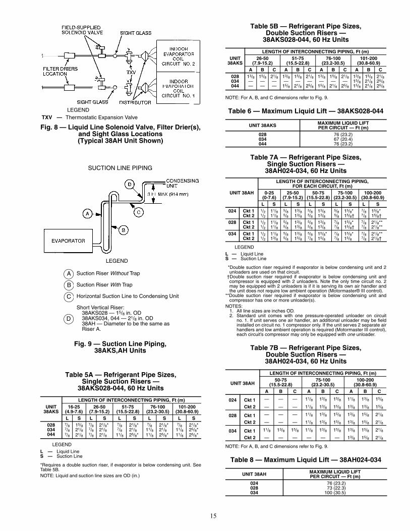
Table 11 — Electrical Data — 38AKS028-044, 60 Hz Units
LEGEND *Units are suitable for use on electrical systems where voltagesupplied to the unit terminals is not below or above the listed min-imum and maximum limits.
†Fuse or HACR circuit breaker.**The 380-v units are export models not listed with UL or UL,
Canada.NOTES:
1. MCA and MOCP values are calculated in accordance with NEC(National Electric Code) (U.S.A. Standard), Article 440.
2. Motor FLA and RLA values are established in accordance with UL(Underwriters Laboratories) Standard 1995 (U.S.A. standard).
Table 12 — Electrical Data — 38AH024-034, 60 Hz Units
LEGEND *Units are suitable for use on electrical systems where voltage sup-plied to unit terminals is not below or above listed minimum andmaximum limits.
†All fans are protected by a single circuit breaker.**Fuse or HACR circuit breaker.
††The 380-v units are export models not listed with UL or UL,Canada.
NOTES:1. MCA and MOCP values are calculated in accordance with NEC
National Electric Code) (U.S.A. Standard), Article 440.2. Motor FLA and RLA values are established in accordance with
UL (Underwriters Laboratories) Standard 1995 (U.S.A. standard).3. The 208/230-v, 460-v, and 575-v base units are UL and UL,
Canada listed.
UNIT38AKS
NOMINALVOLTAGE
VOLTAGERANGE* FLA
COMPRESSOR FAN MOTORS POWER SUPPLY
RLA LRA Qty FLA(ea) MCA MOCP† ICF(3 Ph, 60-Hz) Min Max
028
208/230 187 254 102.2 89.8 446
2
6.2 124.6 200 452.2380** 342 418 53.3 45.5 247 3.9 64.7 110 250.9460 414 508 49.8 43.6 223 3.1 60.7 100 226.1575 518 632 43.3 36.5 164 3.4 52.5 80 167.4
034
208/230 187 254 118.4 106.5 506
2
6.2 145.5 250 512.2380** 342 418 60.4 52.6 280 3.9 72.5 125 283.9460 414 508 56.2 50.0 253 3.1 68.7 110 256.1575 518 632 45.3 38.5 176 3.4 54.9 90 179.4
044
208/230 187 254 165.6 147.5 690
3
6.2 203.0 350 702.4380** 342 418 91.2 79.5 382 3.9 111.1 175 389.8460 414 508 74.7 65.4 345 3.1 91.0 150 351.2575 518 632 67.3 57.1 276 3.4 81.5 125 282.8
FLA — Full Load AmpsHACR — Heating, Air Conditioning, and RefrigerationICF — Maximum Instantaneous Current Flow during starting.
(The point in the starting sequence where the sum of theLRA for the starting compressor, plus the total RLA for allrunning compressors, plus the total FLA for all runningmotors is maximum.)
LRA — Locked Rotor AmpsMCA — Minimum Circuit Amps (Complies with National Electrical
Code [NEC], Section 430-24)MOCP — Maximum Overcurrent ProtectionRLA — Rated Load AmpsUL — Underwriters Laboratories
UNIT38AH
NOMINALVOLTAGE
VOLTAGERANGE*
COMPRESSOR FAN MOTORS† POWER SUPPLYRLA LRA
Qty FLA(ea) MCA MOCP** ICF
3 Ph, 60 Hz Min Max Ckt 1 Ckt 2 Ckt 1 Ckt 2
024
208/230 187 254 39.3 39.3 198 198
2
(1) 5.5 (2) 6.6 100.5 125 249.7380†† 342 418 24.0 24.0 93 93 3.9 61.8 80 124.8
460 414 508 19.6 19.6 99 99 (1) 2.8 (2) 3.3 50.2 60 124.8575 518 632 15.7 15.7 79 79 3.4 42.1 50 101.5
028
208/230 187 254 43.6 43.6 228 228
2
(1) 5.5 (2) 6.6 110.2 150 284.0380†† 342 418 26.4 26.4 104 104 3.9 67.2 90 138.2
460 414 508 22.1 22.1 114 114 (1) 2.8 (2) 3.3 55.8 70 142.3575 518 632 19.7 19.7 91 91 3.4 47.1 60 117.5
034
208/230 187 254 43.6 63.6 228 266
2
(1) 5.5 (2) 6.6 135.2 175 322.0380†† 342 418 26.4 34.3 104 145 3.9 77.0 110 179.2
460 414 508 22.1 30.0 114 120 (1) 2.9 (2) 3.3 65.7 90 148.3575 518 632 17.9 22.9 91 96 3.4 53.3 70 120.7
FLA — Full Load AmpsHACR — Heating, Air Conditioning, and RefrigerationICF — Maximum Instantaneous Current Flow during starting (the
point in the starting sequence where the sum of the LRAfor the starting compressor, plus the total RLA for allrunning compressors, plus the total FLA for all running fanmotors is maximum).
LRA — Locked Rotor AmpsMCA — Minimum Circuit Amps (complies with National Electrical
Code [NEC], Section 430-24)MOCP— Maximum Overcurrent ProtectionRLA — Rated Load AmpsUL — Underwriters Laboratories
19
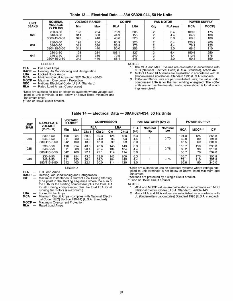
Table 13 — Electrical Data — 38AKS028-044, 50 Hz Units
LEGEND
*Units are suitable for use on electrical systems where voltage sup-plied to unit terminals is not below or above listed minimum andmaximum limits.
†Fuse or HACR circuit breaker.
NOTES:1. The MCA and MOCP values are calculated in accordance with
NEC (National Electrical Code) (U.S.A. Standard), Article 440.2. Motor FLA and RLA values are established in accordance with UL
(Underwriters Laboratories) Standard 1995 (U.S.A. standard).3. 230-v and 346-v units are part-wind-start units; the value under
compressor LRA is for the first winding energized. The 400-vunits are across-the-line-start units; value shown is for all wind-ings energized.
Table 14 — Electrical Data — 38AH024-034, 50 Hz Units
LEGEND *Units are suitable for use on electrical systems where voltage sup-plied to unit terminals is not below or above listed minimum andmaximum.
†All fans are protected by a single circuit breaker.**Fuse or HACR circuit breaker.NOTES:
1. MCA and MOCP values are calculated in accordance with NEC(National Electric Code) (U.S.A. Standard), Article 440.
2. Motor FLA and RLA values are established in accordance withUL (Underwriters Laboratories) Standard 1995 (U.S.A. standard).
UNIT38AKS
NOMINAL VOLTAGE(V-Ph-Hz)
VOLTAGE RANGE* COMPR FAN MOTOR POWER SUPPLY
Min Max RLA LRA Qty FLA (ea) MCA MOCP†
028230-3-50 198 254 76.9 205 2 6.4 109.0 175346-3-50 311 380 44.9 155 2 4.4 64.9 100
380/415-3-50 342 440 43.6 223 2 3.0 60.5 100
034230-3-50 198 254 85.9 220 2 6.4 120.2 200346-3-50 311 380 53.9 176 2 4.4 76.1 125
380/415-3-50 342 440 50.0 253 2 3.0 68.5 110
044230-3-50 198 254 105.1 327 3 6.4 150.6 250346-3-50 311 380 79.5 240 3 4.4 112.6 175
380/415-3-50 342 440 65.4 345 3 3.0 90.8 150
FLA — Full Load AmpsHACR — Heating, Air Conditioning and RefrigerationLRA — Locked Rotor Amps MCA — Minimum Circuit Amps per NEC Section 430-24MOCP — Maximum Overcurrent ProtectionNEC — National Electrical Code (U.S.A. Standard)RLA — Rated Load Amps (Compressor)
UNIT38AH
NAMEPLATEVOLTAGE(V-Ph-Hz)
VOLTAGERANGE* COMPRESSOR FAN MOTORS† (Qty 2) POWER SUPPLY
Min MaxRLA LRA FLA
(ea)Nominal
HpNominal
kW MCA MOCP** ICFCkt 1 Ckt 2 Ckt 1 Ckt 2
024230-3-50 198 254 39.3 39.3 128 128 6.3
1 0.75101.0 125 268.8
346-3-50 311 380 24.0 24.0 93 93 4.4 62.8 80 194.8380/415-3-50 342 400 18.0 18.0 99 99 3.0 46.5 60 204.0
028230-3-50 198 254 43.6 43.6 143 143 6.3
1 0.75110.7 150 298.8
346-3-50 311 380 26.4 26.4 104 104 4.4 68.2 90 216.8380/415-3-50 342 400 22.1 22.1 114 114 3.0 55.7 70 234.0
034230-3-50 198 254 43.6 63.6 143 200 6.3
1 0.75135.7 175 355.8
346-3-50 311 380 26.4 34.3 104 145 4.4 78.1 110 257.8380/415-3-50 342 400 22.1 30.0 114 120 3.0 65.6 90 240.0
FLA — Full Load AmpsHACR — Heating, Air Conditioning and RefrigerationICF — Maximum Instantaneous Current Flow During Starting.
(The point in the starting sequence where the sum ofthe LRA for the starting compressor, plus the total RLAfor all running compressors, plus the total FLA for allrunning fan motors is maximum.)
LRA — Locked Rotor AmpsMCA — Minimum Circuit Amps (complies with National Electri-
cal Code [NEC] Section 430-24) (U.S.A. Standard)MOCP — Maximum Overcurrent ProtectionRLA — Rated Load Amps

20
CONDENSER FANS — The fans must rotate counter-clockwise when viewed from above. If necessary, correct di-rection of fan rotation by interchanging any 2 power inputwires at disconnect switch. Affix crankcase heater decal (locat-ed in installer’s packet) to unit disconnect switch.FIELD CONNECTIONS (See Fig. 11-15)
1. Main Power — Bring wires from the fused disconnectswitch through hole in bottom rail of unit to controlbox and connect to terminals 11, 12, 13 on line sideof terminal block TB1. To comply with NEC Article440-14, the disconnect must be located within sightand readily accessible from the unit.
2. 24-v Control Power — Units have single-point powerconnections. Control circuit is directly connected inter-nally to unit. Maximum current for 24-v control circuit is3.2 amps.NOTE: For wire runs, use the following sizes of insu-lated wire. Tables 15A and 15B show maximum wiresizes.
LEGENDAWG — American Wire Gage
3. ModuPanel™ Control Connections (38AH units) —Refer to Fig. 14 and 15 for field connections.
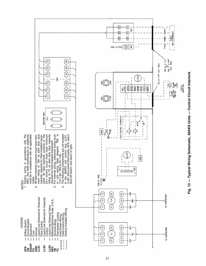
4. Control Circuit Interlock (38AKS units) — An airflowswitch may be installed in the indoor air handler toprevent unit from running when indoor air is not flow-ing. This switch (no. HR81JE001) is available fromthe Service Parts Center, or equivalent can be fieldsupplied. This should be electrically interlocked in thecontrol circuit, between thermostat TC1 (stage 1, cool-ing) and terminal 2/Y1 on TB3. See Fig. 13 for typicalfield wiring. This is in the 24-v circuit. Wires must berun in conduit with ground wire.
5. Transformer Connections — For wiring, see unit labeldiagram, notes 1 and 2, located on inside of compressorcompartment end access door.
UNBALANCED 3-PHASE SUPPLY VOLTAGE — Neveroperate a motor where a phase imbalance in supply voltage isgreater than 2% Use the following formula to determine thepercent voltage imbalance:% Voltage Imbalance
EXAMPLE: Supply voltage is 240-3-60.
AB = 243 vBC = 236 vAC = 238 v
Determine maximum deviation from average voltage:(AB) 243 – 239 = 4 v(BC) 239 – 236 = 3 v(AC) 239 – 238 = 1 v
Maximum deviation is 4 v.Determine percent voltage imbalance:
= 1.7%This amount of phase imbalance is satisfactory as it is be-
low the maximum allowable 2%.
Table 15A — 38AKS028-044, 50/60 Hz —Maximum Wire Sizes
LEGEND
Table 15B — 38AH024-034, 50/60 Hz —Maximum Wire Sizes
LEGEND
Ft (m)0-50
(0-15.2)50-75
(15.2-22.9)Over 75
(Over 22.9)No. 18 AWG(0.82 sq mm)
35 C Min
No. 16 AWG(1.30 sq mm)
35 C Min
No. 14 AWG(2.08 sq mm)
35 C Min
IMPORTANT: Ensure power to the crankcase heater isalways on (except when servicing the unit). If circuitbreakers inside unit shut down the compressor and con-denser fans, crankcase heater remains on.
= 100 xmax voltage deviation from average voltage
average voltage
Average Voltage =243 + 236 + 238
3= 239 v
% Voltage Imbalance = 100 x4
239
IMPORTANT: Contact your local electric utility com-pany immediately if the supply voltage phase imbalanceis more than 2%.
UNIT38AKS V-Ph-Hz WIRE SIZE
028-044
208/230-3-60 350 kcmil (178 sq mm)380-3-60
2/0 AWG (67 sq mm)460-3-60575-3-60230-3-50 350 kcmil (178 sq mm)346-3-50
2/0 AWG (67 sq mm)380/415-3-50
AWG — American Wire Gagekcmil — Thousand Circular Mils
UNIT38AH V-Ph-Hz WIRE SIZE
024-034
208/230-3-60 350 kcmil (178 sq mm)380-3-60
2/0 AWG (67 sq mm)460-3-60575-3-60230-3-50 350 kcmil (178 sq mm)346-3-50
2/0 AWG (67 sq mm)380/415-3-50
AWG — American Wire Gagekcmil — Thousand Circular Mils

21
NO
TE
S:
1.C
B4
prot
ects
TB
2 ci
rcui
t; C
B3
prot
ects
TB
3 ci
rcui
ts.
2.LL
S1
and
LLS
2 ar
e fie
ld s
uppl
ied.
3.T
B2
is in
24-
v ci
rcui
t.4.
On
the
TS
R-0
1 R
elay
Pac
k, th
e ou
tsid
e-ai
r se
nsor
, sup
ply-
air
sen-
sor,
and
dire
ct e
xpan
sion
coi
l sen
sor
are
avai
labl
e as
opt
ions
.5.
For
inf
orm
atio
n on
con
nect
ing
cond
ensi
ng u
nit
to 2
sep
arat
e ai
rha
ndle
rs, c
onta
ct A
pplic
atio
n E
ngin
eerin
g.6.
LLS
val
ve n
o. 1
is t
o be
use
d on
the
low
er (
no.
1) e
vapo
rato
r ci
r-cu
it. T
he L
LS v
alve
no.
2 is
to b
e us
ed o
n th
e up
per
(no.
2)
evap
o-ra
tor
circ
uit.
See
tabl
e be
low
for
reco
mm
ende
d LL
S v
olta
ge.
Fig
. 11
— T
ypic
al C
on
tro
l Wir
ing
Sch
emat
ic, 3
8AH
Un
it —
Pro
gra
mm
able
Th
erm
ost
at
LEG
EN
DC
B—
Circ
uit B
reak
erC
OM
—C
omm
onG
ND
—G
roun
dIF
C—
Indo
or-F
an C
onta
ctor
LL
S—
Liqu
id L
ine
Sol
enoi
dN
EC
—N
atio
nal E
lect
rical
Cod
e(U
.S.A
. Sta
ndar
d)R
V—
Rev
ersi
ng V
alve
TB
—Te
rmin
al B
lock
Fie
ld C
ontr
ol W
iring
Fact
ory
Wiri
ngF
ield
Pow
er W
iring
Indi
cate
s C
omm
on P
oten
tial;
Doe
s N
ot In
dica
te W
iring
*CB
3 pr
otec
ts c
ontr
ol c
ircui
t at t
he fo
llow
ing
unit
volta
ges:
CO
NT
RO
L C
IRC
UIT
PR
OT
EC
TE
D A
T:(V
-Ph
-Hz)
UN
IT (
V-P
h-H
z)
115-
1-60
208/
230-
3-60
460-
3-60
575-
3-60
230-
1-60
380-
3-60
230-
1-50
230-
3-50
346-
3-50
380/
415-
3-50

22
NO
TE
S:
1.C
B4
prot
ects
TB
2 ci
rcui
t; C
B3
prot
ects
TB
3 ci
rcui
t.2.
LLS
1 an
d LL
S2
are
field
sup
plie
d.3.
TB
2 is
in 2
4-v
circ
uit.
4.LL
S v
alve
no.
1 is
to b
e us
ed o
n th
e lo
wer
(no
. 1)
evap
orat
orci
rcui
t. T
he L
LS v
alve
no.
2 is
to b
e us
ed o
n th
e up
per
(no.
2)
evap
orat
or c
ircui
t. S
ee t
able
bel
ow f
or r
ecom
men
ded
LLS
volta
ge.
Fig
. 12
— T
ypic
al C
on
tro
l Wir
ing
Sch
emat
ic, 3
8AH
Un
it —
Sta
nd
ard
Th
erm
ost
at
LEG
EN
DA
HA
—A
djus
tabl
e H
eat A
ntic
ipat
orA
UTO
—A
utom
atic
Cha
ngeo
ver
CB
—C
ircui
t Bre
aker
CC
—C
oolin
g C
ompe
nsat
orG
ND
—G
roun
dIF
C—
Indo
or-F
an C
onta
ctor
LL
S—
Liqu
id L
ine
Sol
enoi
dN
EC
—N
atio
nal E
lect
rical
Cod
e(U
.S.A
. Sta
ndar
d)T
B—
Term
inal
Blo
ckT
C—
The
rmos
tat,
Coo
ling
TH
—T
herm
osta
t, H
eatin
gF
ield
Con
trol
Wiri
ngFa
ctor
y W
iring
Fie
ld P
ower
Wiri
ngIn
dica
tes
Com
mon
Pot
entia
l;D
oes
Not
Indi
cate
Wiri
ng
*CB
3 pr
otec
ts c
ontr
ol c
ircui
t at t
he fo
llow
ing
unit
volta
ges:
CO
NT
RO
L C
IRC
UIT
PR
OT
EC
TE
D A
T:(V
-Ph
-Hz)
UN
IT (
V-P
h-H
z)
115-
1-60
208/
230-
3-60
460-
3-60
575-
3-60
230-
1-60
380-
3-60
230-
1-50
230-
3-50
346-
3-50
380/
415-
3-50
23
Fig
. 13
— T
ypic
al W
irin
g S
chem
atic
, 38A
KS
Un
its
— C
on
tro
l Cir
cuit
Inte
rlo
ck
LEG
EN
DA
FS
—A
irflo
w S
witc
hC
B—
Circ
uit B
reak
erE
QU
IP—
Equ
ipm
ent
FU
—F
use
GN
D—
Gro
und
LL
S1
—Li
quid
Lin
e S
olen
oid
for
Sol
enoi
dD
rop
Con
trol
LL
S2
—Li
quid
Lin
e S
olen
oid
for
Cap
acity
Con
trol
LL
SV
—Li
quid
Lin
e S
olen
oid
Val
veN
EC
—N
atio
nal E
lect
rical
Cod
e, U
.S.A
.T
B—
Term
inal
Blo
ckT
C—
The
rmos
tat,
Coo
ling
Fie
ld P
ower
Wiri
ngF
ield
Con
trol
Wiri
ngFa
ctor
y-In
stal
led
Wiri
ng
NO
TE
S:
1.Fa
ctor
y w
iring
in
ac
cord
ance
w
ith
the
NE
C.
Any
fie
ld m
odifi
catio
ns o
r ad
ditio
nsm
ust
be in
com
plia
nce
with
all
appl
icab
leco
des.
2.A
ll fie
ld in
terlo
ck c
onta
cts
mus
t hav
e m
ini-
mum
ra
ting
of
180
va
pilo
t du
ty
plus
capa
city
req
uire
d fo
r fie
ld-in
stal
led
equi
p-m
ent.
All
field
int
erlo
ck c
onta
cts
in t
he24
-v c
ontr
ol c
ircui
t m
ust
have
min
imum
ratin
g of
70
va p
ilot
duty
plu
s ca
paci
tyre
quire
d fo
r fie
ld-in
stal
led
equi
pmen
t.3.
For
int
erna
l w
iring
, re
fere
nce
wiri
ng b
ook
or
unit
wiri
ng
labe
l di
agra
m.
TB
2 is
115-
1-60
, TB
3 is
24-
1-60
.4.
The
follo
win
g co
mpo
nent
s ar
e no
t loc
ated
in
the
38A
KS
un
it co
ntro
l bo
x:
LLS
1,LL
S2,
fiel
d co
ntro
l the
rmos
tat,
AF
S, a
larm
shut
-off
switc
h, a
nd a
larm
or
light
.

24
54 55 56 51 52 53
6 9 2 1
RY1U1
5 10
Y2 U2
4 7
IFC
66 67 68 57 58 5938 60 61 6263 64 65 50
IFR
FIELD SUPPLIED RELAY
115 V
MODUPANEL ACCESSORY
TB2
STA
GE
6
STA
GE
5
STA
GE
4
STA
GE
3
STA
GE
2
STA
GE
1
LEGEND
IFC — Indoor-Fan ContactorIFR — Indoor-Fan RelayTB — Terminal Block
Terminal Block ConnectionField Accessory WiringFactory Wiring
Fig. 14 — Typical 38AH Unit Field Wiring — ModuPanel™ Controllerwith 38AH024-034 Dual-Circuit Condensing Unit and Air Handler
NOTES:1. Factory wiring is in accordance
with National Electrical Code(NEC) (U.S.A. standard). Fieldmodifications or additions mustbe in compliance with all applica-ble codes.
2. Terminal block is for externalfield control connections. Controlconnections are to be class 2wiring.
3. Replacement of factory wiresmust be with type 105 C wire orits equivalent.
MODUPANEL ACCESSORY
TB2 UNIT 2 TB2 UNIT 1
FIELD SUPPLIEDRELAY
8078 79
STA
GE
9
STA
GE
10
STA
GE
7
STA
GE
8
STA
GE
6
STA
GE
5
10 9 5
U2 U1 Y2
2 1
Y1 R
10
U2
7 G 5
Y2
6 9
U1
2 1
Y1 R
115 V 38 60 61 62 57 58 59 54 55 56 51 52 5375 76 77 72 73 74 69 70 71 66 67 68 63 64 65 50
STA
GE
4
STA
GE
2
STA
GE
3
STA
GE
1
IFR
LEGEND
IFR — Indoor-Fan RelayTB — Terminal Block
Terminal BlockConnection
Unmarked SpliceField Accessory WiringFactory Wiring
NOTES:1. Factory wiring is in accordance
with National Electrical Code(NEC) (U.S.A. standard). Fieldmodifications or additions mustbe in compliance with all applica-ble codes.
2. Terminal block is for externalfield control connections. Controlconnections are to be class 2wiring.
3. Replacement of factory wiresmust be with type 105 C wire orits equivalent.
Fig. 15 — Typical 38AH Unit Field Wiring — VAV ModuPanel Control,Two Dual-Circuit Condensing Units with Air Handler
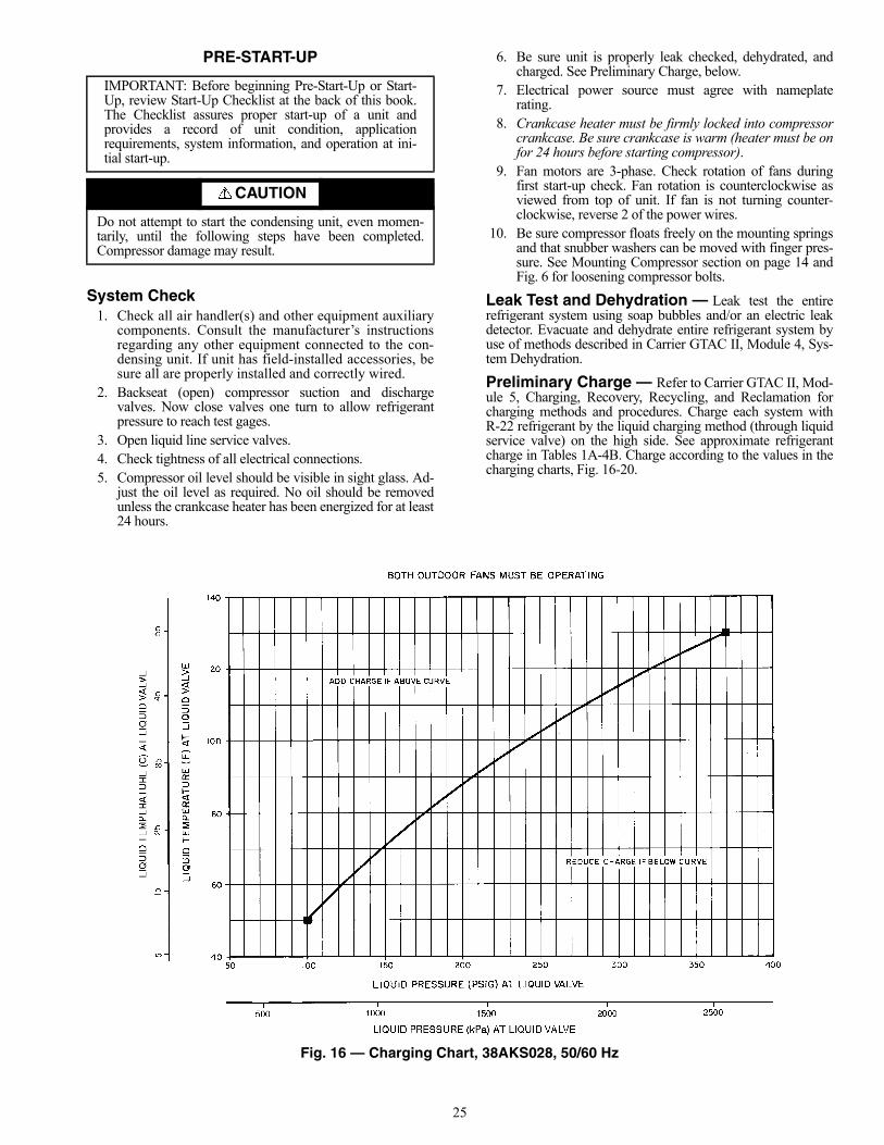
25
PRE-START-UP
System Check1. Check all air handler(s) and other equipment auxiliary
components. Consult the manufacturer’s instructionsregarding any other equipment connected to the con-densing unit. If unit has field-installed accessories, besure all are properly installed and correctly wired.
2. Backseat (open) compressor suction and dischargevalves. Now close valves one turn to allow refrigerantpressure to reach test gages.
3. Open liquid line service valves.4. Check tightness of all electrical connections.5. Compressor oil level should be visible in sight glass. Ad-
just the oil level as required. No oil should be removedunless the crankcase heater has been energized for at least24 hours.
6. Be sure unit is properly leak checked, dehydrated, andcharged. See Preliminary Charge, below.
7. Electrical power source must agree with nameplaterating.
8. Crankcase heater must be firmly locked into compressorcrankcase. Be sure crankcase is warm (heater must be onfor 24 hours before starting compressor).
9. Fan motors are 3-phase. Check rotation of fans duringfirst start-up check. Fan rotation is counterclockwise asviewed from top of unit. If fan is not turning counter-clockwise, reverse 2 of the power wires.
10. Be sure compressor floats freely on the mounting springsand that snubber washers can be moved with finger pres-sure. See Mounting Compressor section on page 14 andFig. 6 for loosening compressor bolts.
Leak Test and Dehydration — Leak test the entirerefrigerant system using soap bubbles and/or an electric leakdetector. Evacuate and dehydrate entire refrigerant system byuse of methods described in Carrier GTAC II, Module 4, Sys-tem Dehydration.
Preliminary Charge — Refer to Carrier GTAC II, Mod-ule 5, Charging, Recovery, Recycling, and Reclamation forcharging methods and procedures. Charge each system withR-22 refrigerant by the liquid charging method (through liquidservice valve) on the high side. See approximate refrigerantcharge in Tables 1A-4B. Charge according to the values in thecharging charts, Fig. 16-20.
IMPORTANT: Before beginning Pre-Start-Up or Start-Up, review Start-Up Checklist at the back of this book.The Checklist assures proper start-up of a unit andprovides a record of unit condition, applicationrequirements, system information, and operation at ini-tial start-up.
CAUTION
Do not attempt to start the condensing unit, even momen-tarily, until the following steps have been completed.Compressor damage may result.
Fig. 16 — Charging Chart, 38AKS028, 50/60 Hz

26
Fig. 17 — Charging Chart, 38AKS034, 50/60 Hz
Fig. 18 — Charging Chart, 38AKS044, 50/60 Hz

27
NOTE: All outdoor fans must be operating.
Fig. 19 — Charging Chart, 38AH024 and 028, 50/60 Hz (Circuits No. 1 and 2)
NOTE: All outdoor fans must be operating.
Fig. 20 — Charging Chart, 38AH034, 50/60 Hz (Circuits No. 1 and 2)
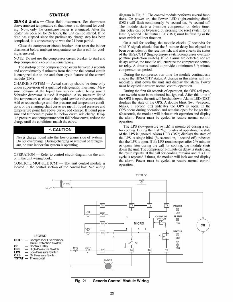
28
START-UP
38AKS Units — Close field disconnect. Set thermostatabove ambient temperature so that there is no demand for cool-ing. Now, only the crankcase heater is energized. After theheater has been on for 24 hours, the unit can be started. If notime has elapsed since the preliminary charge step has beencompleted, it is unnecessary to wait the 24-hour period.
Close the compressor circuit breaker, then reset the indoorthermostat below ambient temperature, so that a call for cool-ing is ensured.NOTE: Do not use the compressor circuit breaker to start andstop compressor, except in an emergency.
The start-up of the compressor can occur between 3 secondsand approximately 5 minutes from the time the control circuitis energized due to the anti-short cycle feature of the controlmodule (CM).CHARGE SYSTEM — Actual start-up should be done onlyunder supervision of a qualified refrigeration mechanic. Mea-sure pressure at the liquid line service valve, being sure aSchrader depressor is used if required. Also, measure liquidline temperature as close to the liquid service valve as possible.Add or reduce charge until the pressure and temperature condi-tions of the charging chart curve are met. If liquid pressure andtemperature point fall above curve, add charge. If liquid pres-sure and temperature point fall below curve, add charge. If liq-uid pressure and temperature point fall below curve, reduce thecharge until the conditions match the curve.
OPERATION — Refer to control circuit diagram on the unit,or in the unit wiring book.CONTROL MODULE (CM) — The unit control module islocated in the control section of the control box. See wiring
diagram in Fig. 21. The control module performs several func-tions. On power up, the Power LED (light-emitting diode)(DS1) will flash continuously 1/4 second on, 1/4 second off.The module starts a 3-minute compressor on delay timer.This delay can be bypassed by pressing the reset switch for atleast 1/2 second. The Status LED (DS3) must be flashing or thereset switch will not function.
On a call for cooling, the module checks (7 seconds) forvalid Y signal; checks that the 3-minute delay has elapsed orbeen overridden by the reset switch; and also checks the statusof the HPS/COTP (high-pressure switch/compressor overtem-perature protection switch). If no alarms are detected nor aredelays active, the module will energize the compressor contac-tor relay. A timer is started to provide a minimum 31/2-minutecompressor run period.
During the compressor run time the module continuouslychecks the HPS/COTP status. A change in this status will im-mediately shut down the unit and display the alarm. Powermust be cycled to restore normal control operation.
During the first 60 seconds of operation, the OPS (oil pres-sure switch) state is monitored but ignored. After this time ifthe OPS is open, the unit will be shut down. Alarm LED (DS2)displays the state of the OPS. A double blink (two 1/4-secondblinks, 1 second off) indicates the OPS is open. If theOPS opens during operation and remains open for longer than60 seconds, the module will lockout unit operation and displaythe alarm. Power must be cycled to restore normal controloperation.
The LPS (low-pressure switch) is monitored during a callfor cooling. During the first 21/2 minutes of operation, the stateof the LPS is ignored. Alarm LED (DS2) displays the state ofthe LPS. A single blink (1/4 second on, 1 second off) indicatesthat the LPS is open. If the LPS remains open after 21/2 minutesor opens later during the call for cooling, the module shutsdown the unit. The compressor 3-minute on delay is started andthe cycle repeats. If the call for cooling remains and this LPScycle is repeated 3 times, the module will lock out and displaythe alarm. Power must be cycled to restore normal controloperation.
CAUTION
Never charge liquid into the low-pressure side of system.Do not overcharge. During charging or removal of refriger-ant, be sure indoor fan system is operating.
T11
24VAC
L1
L2 OR N
T”STAT “Y”
DS1
POWER
ALARM
DS2
STATUS
DS3
K1
DS4
CRMICRO
T3 T2 T1
OVERRIDESWITCH
K1
T6
K2
T4 T5
ALARM
T7
T8
HPS COTP
OPS
T9
LPST10
LEGENDCOTP — Compressor Overtemper-
ature Protection SwitchCR — Control RelayHPS — High-Pressure SwitchLPS — Low-Pressure SwitchOPS — Oil Pressure SwitchTSTAT — Thermostat
Fig. 21 — Generic Control Module Wiring

29
When the call for cooling is satisfied and the compressorhas run for at least 31/2 minutes, the module shuts the unitdown. The control module restarts the compressor 3-minuteon delay timer.TIME-DELAY RELAY (TDR) (50 Hz Only) — This solid-state delay-on-make relay is factory set for a 1-second delay.The number 1 DIP switch is set to the ON position, and all theother DIP switches are set to the OFF position. Once the con-trol relay (CR) is energized, the compressor contactor C1 ispowered, and the first set of compressor windings is energized.After the 1-second time delay, contactor C1A is powered andthe second set of compressor windings is energized (part-windstart).COMPLETE UNIT STOPPAGECauses — Interruption of supplied power, compressorovertemperature protection, open HPS, open OPS, or openLPS causes compressor stoppage.
The LPS is governed by the 3-strikes rule. Three trip cyclesare allowed before the unit is locked out. The alarm LED willflash a code for the cause of the lockout.Restart — The unit recycles and restarts automatically underthe CPM when power is restored or cycled. Complete stoppageof the unit by the CPM, or compressor circuit breaker requiresmanual resetting of the control circuit. To restart the CPMwhen the HPS is tripped, it is necessary to interrupt power tothe unit, restarting the CPM logic. It is necessary to manuallyreset the compressor circuit breaker at the unit.
If the LPS is not closed within 21/2 minutes after compres-sor starts, the compressor and the outdoor fans are shut off. Theunit remains off for 3 minutes. After 3 minutes the system isrestarted. The LPS is again bypassed for 21/2 minutes. Thiscycle will repeat 3 times if the cause of the LPS open is noteliminated. Operation will be locked out after the third cycleuntil CPM power is cycled.
If sufficient compressor oil pressure has not been built with-in 1 minute after the compressor starts, the unit is locked out.The LPS may have to be manually reset at the unit. Power mustbe cycled to the CPM to reset the controller.
38AH Units — Compressor crankcase heaters must be onfor 24 hours before start-up. To energize the crankcase heaters,set the space thermostat above the ambient so there will be nodemand for cooling. Close the field disconnect and turn on thefan circuit breakers. Leave the compressor circuit breakers off/open. The crankcase heaters are now energized.
After the heater has been on for 24 hours, the unit can bestarted. If no time has elapsed since the preliminary charge stephas been completed, it is unnecessary to wait the 24-hourperiod.PRELIMINARY CHECKS
1. Ensure that compressor service valves are backseated.2. Verify that each compressor floats freely on its mounting
springs.3. Check that electric power supply agrees with unit name-
plate data.4. Verify that compressor crankcase heaters are securely in
place.5. Check that compressor crankcase heaters have been on at
least 24 hours.6. Note that compressor oil level is visible in the sight glass.
7. Recheck for leaks using same procedure as previouslyoutlined in Pre-Start-Up section, Leak Test and Dehydra-tion, on page 25.
8. If any leaks are detected, evacuate and dehydrate as pre-viously outlined in Pre-Start-Up section, Leak Test andDehydration, on page 25.
PRELIMINARY OIL CHARGE — Each compressor is fac-tory charged with oil. When oil is checked at start-up, it may benecessary to add or remove oil to bring it to the proper level.START UNIT — The field disconnect is closed, the fan circuitbreaker is closed, and the space thermostats are set above ambi-ent so that there is no demand for cooling. Only the crankcaseheaters will be energized.
Next, close the compressor circuit breakers and then resetspace thermostat TC1 below ambient so that a call for stageone cooling is ensured. If compressor does not start, set ther-mostat lower.NOTE: Do not use circuit breakers to start and stop the com-pressor except in an emergency.
Start-up of circuit no. 1 compressor will be delayed fromone second to 5 minutes from the time the call for cooling isinitiated. The TC2 (thermostat contacts 2) close 1.5° F (0.7° C)lower than TC1. After these contacts close, start-up of circuitno. 2 compressor will be delayed from one second to 5 minutesfrom the time the call for cooling is initiated (see Fig. 22).
ADJUST REFRIGERANT CHARGE
NOTE: Actual start-up and all refrigerant charge modificationsshould be done only under supervision of a qualified refrigera-tion technician.
With all fans operating, adjust the refrigerant charge in ac-cordance with the unit charging charts (Fig. 16-20).
Measure pressure at the liquid line service valve, being sureSchrader depressor is used if required. Also, measure liquidline temperature as close to the liquid service valve as possible.Add charge until the pressure and temperature conditions of thecharging chart curve are met. If liquid pressure and temperaturepoint fall above curve, add charge. If liquid pressure and tem-perature point fall below curve, recover refrigerant to reducethe charge until the conditions match the curve.
If the liquid line sight glass is cloudy or shows bubbles inrefrigerant, check refrigerant charge again. Ensure all fans areoperating. Also ensure maximum allowable liquid lift has notbeen exceeded. If charged per chart and if the sight glass is stillnot clear, check for a plugged filter drier or a partially closedsolenoid valve. Replace or repair, as needed.CHECK COMPRESSOR OIL LEVEL — After adjusting therefrigerant charge, allow each circuit to run fully loaded for
CAUTION
If unit or circuit stoppage occurs more than once due to anysafety device, the trouble should be corrected before anyattempt to restart.
CAUTION
Never charge liquid into the low-pressure side of system.Do not overcharge. During charging or removal of refriger-ant, be sure indoor-fan system is operating.
Fig. 22 —Timer Sequence Chart

30
20 minutes. Running oil level should be within view of thecrankcase sight glass. Stop the compressors at the field powersupply disconnect and check the crankcase oil level. Add oilonly if necessary to bring the oil into view in the sight glass. Ifoil is added, run the circuit for an additional 10 minutes, thenstop and check oil level. If the level remains low, check the pip-ing system for proper design for oil return; also, check the sys-tem for leaks.
If the initial check shows too much oil (too high in the sightglass) remove oil to proper level. See Oil Charge, page 35, forproper procedure for adding and removing oil.
When the above checks are complete, repeat the procedurewith the unit operating at minimum load conditions. For thisminimum load check, operate each circuit’s compressor indi-vidually and unloaded to minimum step.
Unload the compressor(s) by turning the control set pointadjustment nut counterclockwise until the adjustment nutstops. The unloader is now at 0 psig (0 kPa) set point. If electricactuated unloaders are installed, energize the solenoid to un-load the compressor.
Return unloader to original setting after checks arecomplete.FINAL CHECKS — Ensure all safety controls are operating,control panel covers are on, and the service panels are in place.
Sequence of Operation38AKS UNITS — When a space thermostat calls for cooling,the no. 1 condenser fan and compressor start after a CM validsignal time delay of 7 seconds. If an optional airflow switch isused, compressor and no. 1 condenser fan will not start untilsufficient indoor airflow has closed the switch. After 7 seconds,the compressor starts and the liquid line solenoid valve forsolenoid drop control opens. The crankcase heater is deener-gized. If the head pressure reaches 260 psig (1792 kPa), thesecond condenser fan starts. Fan no. 3 (38AKS044 only) startsif outdoor ambient air rises above 80 F (26.7 C).
If cooling demand is low, suction pressure at the compressordrops. As the pressure drops, the compressor unloads 1 or2 banks of cylinders as required. If cooling demand is high and2-stage operation is used, the second stage of the thermostatactivates the capacity control liquid line solenoid which acti-vates the second stage evaporator coil. The compressor cylin-ders load or unload in response to compressor suction pressureto meet evaporator load.
When the compressor starts, the LPS is bypassed for thefirst 21/2 minutes of operation. If the LPS opens after 21/2 min-utes, the compressor is shut down and cannot restart until the3 minute anti-short-cycle timer expires.
As the space cooling load is satisfied, the second stage ofthe thermostat opens, and closes the field-supplied capacitycontrol liquid line solenoid valve to deactivate the second stagecoil. The compressor adjusts the number of active cylinders tomeet the new load. When the space temperature is satisfied, thefirst stage of the thermostat opens, deenergizing the controlrelay. The compressor stops and the crankcase heater isenergized, preventing refrigerant migration to the compressorduring the off cycle. The liquid line solenoid closes (solenoiddrop refrigerant control) and the 3-minute compressor anti-short-cycle timer is energized.38AH STANDARD CONSTANT VOLUME UNIT WITH2-STAGE COOLING THERMOSTAT — Seven seconds af-ter a thermostat call for the first stage of cooling, compressorno. 1 and the outdoor fans start. The no. 2 fan only starts if theoutdoor ambient temperature is above 70 F (21.1 C). The oil-pressure switch and the low-pressure switch are bypassed for1 and 21/2 minutes, respectively. If either the low-pressureswitch or oil pressure switch remain open after the delay, theunit shuts down and goes into alarm mode. The indoor-fanmotor starts immediately whenever there is a call for cooling. If
a liquid line solenoid valve has been installed (for refrigerantcontrol during the off cycle), then the solenoid valve for com-pressor no. 1 opens immediately upon a call for cooling.
On standard units, compressor no. 1 operates either fullyloaded or at one step of unloading, depending on the suctionpressure, which is dependent on the evaporator load conditions.
As the cooling demand increases, the thermostat calls forthe second stage of cooling. Within 7 seconds from a call forthe second stage of cooling, compressor no. 2 starts. The oilswitch and low-pressure switch for circuit no. 2 are bypassedduring start-up.
As the cooling load is satisfied, the thermostat stops the callfor the second stage of cooling, which in turn deenergizes com-pressor no. 2, closes the no. 2 liquid line solenoid (if installed)and energizes the compressor no. 2 crankcase heater.
If the space temperature continues to decrease, then thethermostat stops the call for the first stage of cooling, whichthen deenergizes compressor no. 1 and the outdoor fans, closesthe no. 1 liquid line solenoid valve (if installed), and energizesthe compressor no. 1 crankcase heater.
The unit controls prevent both compressors from reenergiz-ing within 3 minutes from a previous call for operation.
If the unit safeties trip during operation, refer to the ControlModule section on page 28, and to page 40 of the Trouble-shooting section. To reset the lockout mode, cycle the unitpower.NOTE: If the thermostat fan switch is in the auto position, theindoor fan cycles on and off as the thermostat calls for cooling(or heating). If the switch is in the continuous position, the fanruns when the outdoor unit is powered.38AH OPTIONAL VARIABLE AIR VOLUME UNIT WITHMODUPANEL™ CONTROL — The ModuPanel control reg-ulates up to 10 stages of cooling to maintain a leaving-air tem-perature for variable air volume (VAV) applications. Whenconnected to one 38AH condensing unit, only 6 stages areused. See Table 16 for unit loading and compressor operatingsequence.
When the timeclock connected to the panel closes, theindoor-fan contactor is energized through a field-supplied re-lay. (The relay must be a pilot-duty SPST relay with 115-v coiland 30 va maximum coil draw.) After the time delays pro-grammed into the ModuPanel™ control have elapsed, and withthe leaving air above the set point, the stages of mechanicalcooling are sequenced as follows:
1. Stage 1 starts compressor no. 1 with 2 banks of cylin-ders unloaded (1/3 loaded). Both unloader solenoids areenergized.
2. Stage 2 loads one bank of compressor no. 1 cylinders(2/3 loaded) by deenergizing unloader solenoid no. 1.
3. Stage 3 loads the second bank of compressor no. 1 bydeenergizing unloader solenoid no. 2.
4. Stage 4 starts compressor no. 2 and unloads 2 banks ofcompressor no. 1 cylinders unloaded (1/3 loaded). Bothunloader solenoids are energized.
5. Stage 5 loads one bank of compressor no. 1 cylinders (2/3loaded) by deenergizing unloader solenoid no. 1.
6. Stage 6 loads one bank of compressor no. 1 cylinders(fully loaded) by deenergizing unloader solenoid no. 2.
TWO 38AH OPTIONAL VARIABLE AIR VOLUMEUNITS WITH A SINGLE MODUPANEL CONTROL —The ModuPanel control regulates up to 10 stages of cooling tomaintain a leaving-air temperature for variable air volume(VAV) applications. When connected to two 38AH condensingunits, all 10 stages are used. See Table 17 for unit loading andcompressor operating sequence.
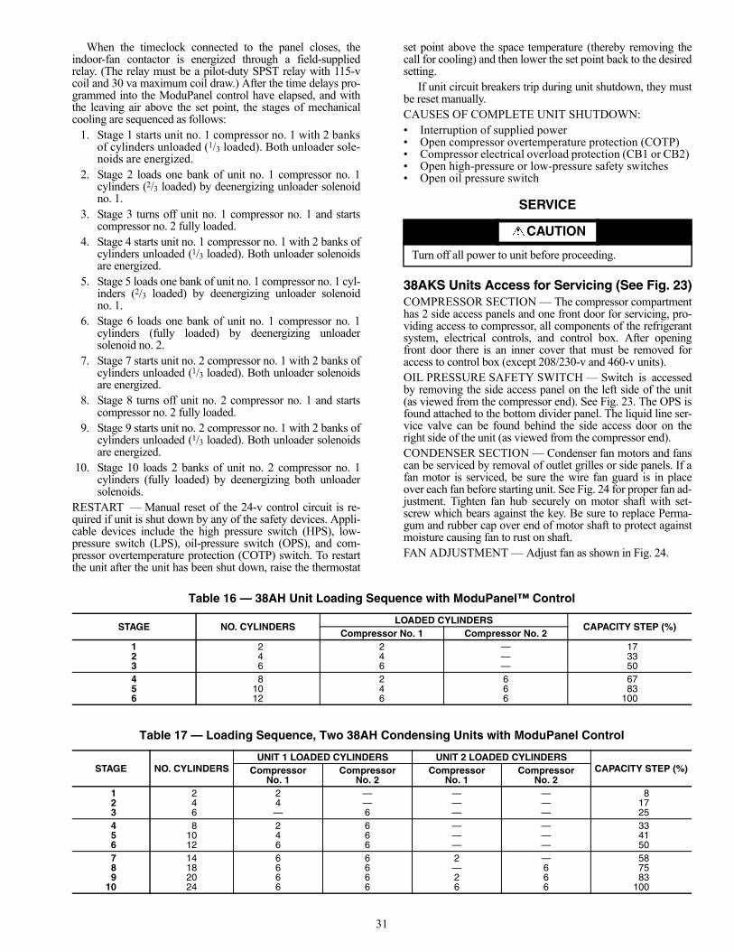
31
When the timeclock connected to the panel closes, theindoor-fan contactor is energized through a field-suppliedrelay. (The relay must be a pilot-duty SPST relay with 115-vcoil and 30 va maximum coil draw.) After the time delays pro-grammed into the ModuPanel control have elapsed, and withthe leaving air above the set point, the stages of mechanicalcooling are sequenced as follows:
1. Stage 1 starts unit no. 1 compressor no. 1 with 2 banksof cylinders unloaded (1/3 loaded). Both unloader sole-noids are energized.
2. Stage 2 loads one bank of unit no. 1 compressor no. 1cylinders (2/3 loaded) by deenergizing unloader solenoidno. 1.
3. Stage 3 turns off unit no. 1 compressor no. 1 and startscompressor no. 2 fully loaded.
4. Stage 4 starts unit no. 1 compressor no. 1 with 2 banks ofcylinders unloaded (1/3 loaded). Both unloader solenoidsare energized.
5. Stage 5 loads one bank of unit no. 1 compressor no. 1 cyl-inders (2/3 loaded) by deenergizing unloader solenoidno. 1.
6. Stage 6 loads one bank of unit no. 1 compressor no. 1cylinders (fully loaded) by deenergizing unloadersolenoid no. 2.
7. Stage 7 starts unit no. 2 compressor no. 1 with 2 banks ofcylinders unloaded (1/3 loaded). Both unloader solenoidsare energized.
8. Stage 8 turns off unit no. 2 compressor no. 1 and startscompressor no. 2 fully loaded.
9. Stage 9 starts unit no. 2 compressor no. 1 with 2 banks ofcylinders unloaded (1/3 loaded). Both unloader solenoidsare energized.
10. Stage 10 loads 2 banks of unit no. 2 compressor no. 1cylinders (fully loaded) by deenergizing both unloadersolenoids.
RESTART — Manual reset of the 24-v control circuit is re-quired if unit is shut down by any of the safety devices. Appli-cable devices include the high pressure switch (HPS), low-pressure switch (LPS), oil-pressure switch (OPS), and com-pressor overtemperature protection (COTP) switch. To restartthe unit after the unit has been shut down, raise the thermostat
set point above the space temperature (thereby removing thecall for cooling) and then lower the set point back to the desiredsetting.
If unit circuit breakers trip during unit shutdown, they mustbe reset manually.CAUSES OF COMPLETE UNIT SHUTDOWN:• Interruption of supplied power• Open compressor overtemperature protection (COTP)• Compressor electrical overload protection (CB1 or CB2) • Open high-pressure or low-pressure safety switches• Open oil pressure switch
SERVICE
38AKS Units Access for Servicing (See Fig. 23)COMPRESSOR SECTION — The compressor compartmenthas 2 side access panels and one front door for servicing, pro-viding access to compressor, all components of the refrigerantsystem, electrical controls, and control box. After openingfront door there is an inner cover that must be removed foraccess to control box (except 208/230-v and 460-v units).OIL PRESSURE SAFETY SWITCH — Switch is accessedby removing the side access panel on the left side of the unit(as viewed from the compressor end). See Fig. 23. The OPS isfound attached to the bottom divider panel. The liquid line ser-vice valve can be found behind the side access door on theright side of the unit (as viewed from the compressor end).CONDENSER SECTION — Condenser fan motors and fanscan be serviced by removal of outlet grilles or side panels. If afan motor is serviced, be sure the wire fan guard is in placeover each fan before starting unit. See Fig. 24 for proper fan ad-justment. Tighten fan hub securely on motor shaft with set-screw which bears against the key. Be sure to replace Perma-gum and rubber cap over end of motor shaft to protect againstmoisture causing fan to rust on shaft.FAN ADJUSTMENT — Adjust fan as shown in Fig. 24.
Table 16 — 38AH Unit Loading Sequence with ModuPanel™ Control
Table 17 — Loading Sequence, Two 38AH Condensing Units with ModuPanel Control
CAUTION
Turn off all power to unit before proceeding.
STAGE NO. CYLINDERSLOADED CYLINDERS
CAPACITY STEP (%)Compressor No. 1 Compressor No. 2
1 2 2 — 172 4 4 — 333 6 6 — 504 8 2 6 675 10 4 6 836 12 6 6 100
STAGE NO. CYLINDERSUNIT 1 LOADED CYLINDERS UNIT 2 LOADED CYLINDERS
CAPACITY STEP (%)CompressorNo. 1
CompressorNo. 2
CompressorNo. 1
CompressorNo. 2
1 2 2 — — — 82 4 4 — — — 173 6 — 6 — — 254 8 2 6 — — 335 10 4 6 — — 416 12 6 6 — — 507 14 6 6 2 — 588 18 6 6 — 6 759 20 6 6 2 6 83
10 24 6 6 6 6 100
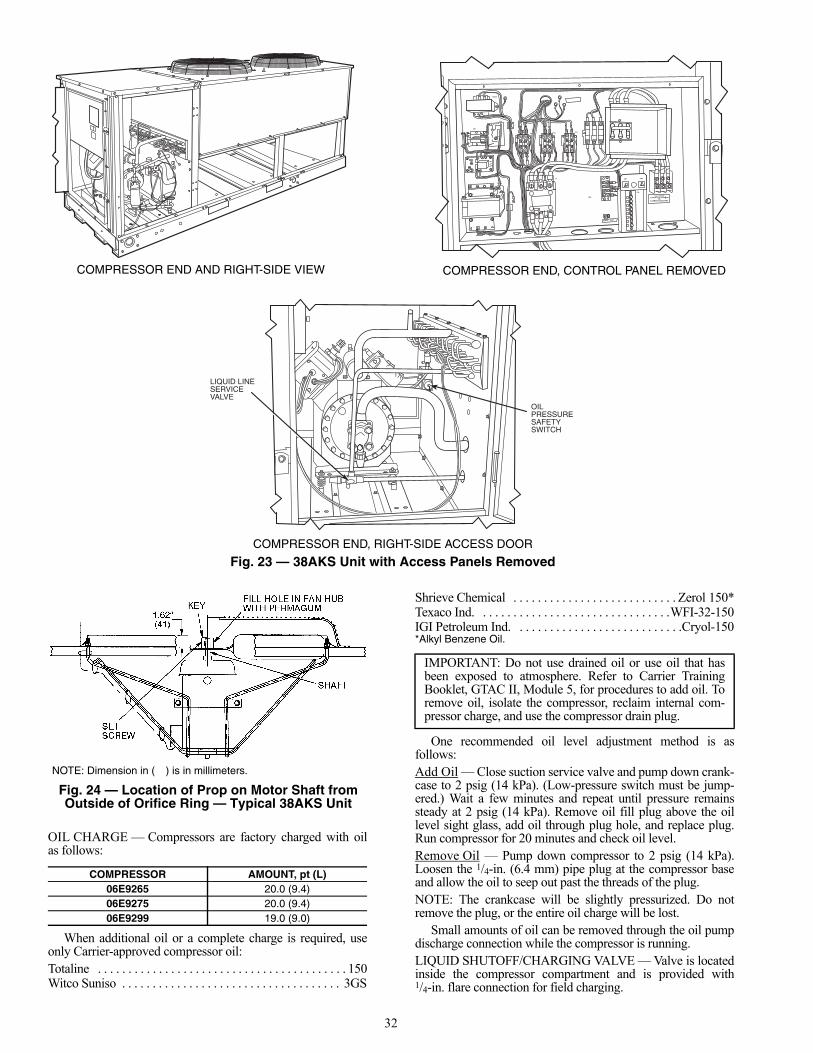
32
OIL CHARGE — Compressors are factory charged with oilas follows:
When additional oil or a complete charge is required, useonly Carrier-approved compressor oil:Totaline . . . . . . . . . . . . . . . . . . . . . . . . . . . . . . . . . . . . . . . . . 150Witco Suniso . . . . . . . . . . . . . . . . . . . . . . . . . . . . . . . . . . . . 3GS
Shrieve Chemical . . . . . . . . . . . . . . . . . . . . . . . . . . . Zerol 150*Texaco Ind. . . . . . . . . . . . . . . . . . . . . . . . . . . . . . . .WFI-32-150IGI Petroleum Ind. . . . . . . . . . . . . . . . . . . . . . . . . . . .Cryol-150*Alkyl Benzene Oil.
One recommended oil level adjustment method is asfollows:Add Oil — Close suction service valve and pump down crank-case to 2 psig (14 kPa). (Low-pressure switch must be jump-ered.) Wait a few minutes and repeat until pressure remainssteady at 2 psig (14 kPa). Remove oil fill plug above the oillevel sight glass, add oil through plug hole, and replace plug.Run compressor for 20 minutes and check oil level.Remove Oil — Pump down compressor to 2 psig (14 kPa).Loosen the 1/4-in. (6.4 mm) pipe plug at the compressor baseand allow the oil to seep out past the threads of the plug.NOTE: The crankcase will be slightly pressurized. Do notremove the plug, or the entire oil charge will be lost.
Small amounts of oil can be removed through the oil pumpdischarge connection while the compressor is running.LIQUID SHUTOFF/CHARGING VALVE — Valve is locatedinside the compressor compartment and is provided with1/4-in. flare connection for field charging.
COMPRESSOR AMOUNT, pt (L)06E9265 20.0 (9.4)06E9275 20.0 (9.4)06E9299 19.0 (9.0)
IMPORTANT: Do not use drained oil or use oil that hasbeen exposed to atmosphere. Refer to Carrier TrainingBooklet, GTAC II, Module 5, for procedures to add oil. Toremove oil, isolate the compressor, reclaim internal com-pressor charge, and use the compressor drain plug.
LIQUID LINESERVICEVALVE
OILPRESSURESAFETYSWITCH
COMPRESSOR END AND RIGHT-SIDE VIEW
TRAN2
CB1 CB2
TB3
FC3FC2FC
CM
CR1
TRAN1
TB2
C1
COMPRESSOR END, CONTROL PANEL REMOVED
COMPRESSOR END, RIGHT-SIDE ACCESS DOOR
Fig. 23 — 38AKS Unit with Access Panels Removed
NOTE: Dimension in ( ) is in millimeters.
Fig. 24 — Location of Prop on Motor Shaft fromOutside of Orifice Ring — Typical 38AKS Unit
a38-3177tf

33
CAPACITY CONTROL — Capacity control is by 2 suctionpressure actuated unloaders. Each controls 2 cylinders.Unloaders are factory set, but may be field adjusted. Number 1unloader is on cylinder bank on same side of compressor asterminal box.Control Set Point — The control set point (cylinder loadpoint) is adjustable from 0 to 85 psig (0 to 586 kPa). To adjust,turn control set point adjustment nut (Fig. 25) clockwise to itsbottom stop. In this position, set point is 85 psig (586 kPa).Then, turn adjustment counterclockwise to desired control setpoint. Every full turn counterclockwise decreases set point by7.5 psig (52 kPa).Pressure Differential — The pressure differential (differencebetween cylinder load and unload points) is adjustable from 6to 22 psig (41 to 152 kPa). To adjust, turn pressure differentialadjustment screw (Fig. 25) counterclockwise to its backstopposition. In this position, differential is 6 psig (41 kPa). Then,turn adjustment clockwise to desired pressure differential.Every full turn clockwise increases differential by 1.5 psig(10 kPa).
OIL PRESSURE — The OPS in the control circuit stops thecompressor and unit, if proper oil pressure differential is notestablished at start-up or maintained during operation. If OPSstops the unit, determine the cause and correct before restartingunit. Failure to do so will constitute abuse. Equipment failuredue to abuse may void the warranty.COMPRESSOR PROTECTIONCircuit Breaker — Calibrated trip manual reset, ambient com-pensated, magnetic breaker protects against motor overloadand locked rotor conditions.Control Module Timer — This control protects compressoragainst short cycling. See Sequence of Operation section onpage 30.Crankcase Heater — This minimizes absorption of liquidrefrigerant by oil in crankcase during brief or extended shut-down periods.
HIGH-PRESSURE SWITCH — This switch has fixed, non-adjustable settings. Switch is mounted on the compressor. (SeeTable 18.)
Table 18 — 38AKS Pressure Switch Settings, psig (kPa)
LOW-PRESSURE SWITCH — This switch has fixed, non-adjustable settings. Switch is mounted on the compressor. (SeeTable 18.)HEAD PRESSURE CONTROL — Control maintains ade-quate discharge pressure under low ambient temperature con-ditions. See Table 19.Fan Cycling — These 38AKS units have standard provisionfor fully automatic intermediate-season head pressure controlthrough condenser fan cycling. Fan no. 2 is cycled by a fancycling pressure switch (FCPS) which responds to variation indischarge pressure. The pressure sensor is located in the liquidline of the refrigerant circuit. Fan no. 3 cycling is controlled byoutdoor-air temperature through an air temperature switch(ATS) (38AKS044 units only).
The ATS is located in the lower divider panel between thecompressor compartment and condenser section. Through ahole in the panel, the sensing element is exposed to air enteringthe no. 1 fan compartment. Fan no. 1 is noncycling. Table 20shows the operating settings of the FCPS and the ATS.
Table 19 — 38AKS Minimum Outdoor-AirOperating Temperature
Table 20 — 38AKS Fan Cycling Controls
38AH Units Access for ServicingCOMPRESSOR SECTION (See Fig. 26.) — The compres-sor compartment has 2 side panels and one end door for serviceaccess to compressors, refrigeration system components, elec-trical controls, and control box. After opening the end door, aninner cover must be removed for access to control box.CONDENSER SECTION — Condenser-fan motors and fanscan be serviced by removal of outlet grilles or side panels. If afan motor is serviced, be sure the wire fan guard is in placeover each fan before starting unit. See Fig. 27 for proper fan ad-justment. Tighten fan hub securely on motor shaft with set-screw which bears against the key. Be sure to replacePermagum and rubber cap over end of motor shaft to protectagainst moisture causing fan to rust on shaft. Recheck rotationof fan(s) after service work on motors.FAN ADJUSTMENT — See Fig. 27.
IMPORTANT: Never open any switch or disconnect thatdeenergizes the crankcase heater unless unit is being ser-viced or is to be shut down for a prolonged period. After aprolonged shutdown on a service job, energize the crank-case heater for 24 hours before starting the compressor.
HIGH PRESSURE LOW PRESSUREOpen Close Open Close
426 ± 7(2937 ± 48)
320 ± 20(2206 ± 138)
27 ± 3(186 ± 21)
44 ± 5(303 ± 34)
UNIT38AKS
COMPRCAP. (%)
CONDTEMP,F (C)
MIN OUTDOOR TEMP, F (C)
StandardUnit
Low AmbientControl
(Motormaster®)
028100 90 (32) 31 (–1) –20 (–29)67 80 (27) 35 (2) –20 (–29)33 70 (21) 43 (6) –20 (–29)
034100 90 (32) 30 (–1) –20 (–29)67 80 (27) 34 (1) –20 (–29)33 70 (21) 42 (6) –20 (–29)
044100 90 (32) 25 (–4) –20 (–29)67 80 (27) 30 (–1) –20 (–29)33 70 (21) 35 (2) –20 (–29)
CONTROL BY SWITCH OPENS SWITCH CLOSESTemp, F (C) 70 ± 3 (21 ± 1.7) 80 ± 3 (27 ± 1.7)Pressure,psig (kPa) 160 ± 10 (1103 ± 69) 255 ± 10 (1793 ± 103)
Fig. 25 — Capacity Control Valve

34
LIQUID LINESERVICEVALVE
LIQUID LINE SERVICE VALVE LOCATION
CIRCUIT NO. 1
06D COMPRESSOR WITH PAN
CIRCUIT NO. 2
Fig. 26 — 38AH Unit with Access Panels Removed

35
OIL CHARGE — Compressors are factory charged with oilas follows:
When additional oil or a complete charge is required, useonly Carrier-approved compressor oil:Totaline . . . . . . . . . . . . . . . . . . . . . . . . . . . . . . . . . . . . . . . . . 150Witco Suniso . . . . . . . . . . . . . . . . . . . . . . . . . . . . . . . . . . . . .3GSShrieve Chemical . . . . . . . . . . . . . . . . . . . . . . . . . . . Zerol 150*Texaco Ind. . . . . . . . . . . . . . . . . . . . . . . . . . . . . . . . WFI-32-150IGI Petroleum Ind. . . . . . . . . . . . . . . . . . . . . . . . . . . .Cryol-150*Alkyl Benzene Oil.
One recommended oil level adjustment method is asfollows:Add Oil — Close suction service valve and pump down crank-case to 2 psig (14 kPa). (Low-pressure switch must be jump-ered.) Wait a few minutes and repeat until pressure remainssteady at 2 psig (14 kPa). Remove oil fill plug above the oillevel sight glass, add oil through plug hole, and replace plug.Run compressor for 20 minutes and check oil level.Remove Oil — Pump down compressor to 2 psig (14 kPa).Loosen the 1/4-in. (6.4 mm) pipe plug at the compressor baseand allow the oil to seep out past the threads of the plug.NOTE: The crankcase will be slightly pressurized. Do notremove the plug, or the entire oil charge will be lost.
Small amounts of oil can be removed through the oil pumpdischarge connection while the compressor is running.LIQUID SHUTOFF/CHARGING VALVE — Valve is locat-ed inside the compressor compartment and is provided with1/4-in. flare connection for field charging.CAPACITY CONTROL, SUCTION PRESSURE-ACTUATED UNLOADERS — Each unloader controls2 cylinders. Unloaders are factory set but may be fieldadjusted.Control Set Point — The control set point (cylinder loadpoint) is adjustable from 0 to 85 psig (0 to 586 kPa). To adjust,turn control set point adjustment nut (Fig. 25) clockwise to itsbottom stop. In this position, set point is 85 psig (586 kPa).Then turn adjustment counterclockwise to desired control set
point. Every full turn counterclockwise decreases set point by7.5 psig (51.7 kPa).Pressure Differential — The pressure differential (differencebetween cylinder load and unload points) is adjustable from 6to 22 psig (41 to 15.2 kPa). To adjust, turn pressure differentialadjustment screw (Fig. 25) counterclockwise to its backstopposition. In this position, differential is 6 psig (41 kPa). Then,turn adjustment clockwise to desired pressure differential.Every full turn clockwise increases differential by 1.5 psig(10.3 kPa).CAPACITY CONTROL, ELECTRICALLY OPERATEDUNLOADERS (VARIABLE AIR VOLUME, FACTORY-INSTALLED OPTION UNITS) — Each unloader controls2 cylinders. Electric unloaders are not field adjustable. Circuitno. 1 compressor on this factory-installed option has 2 electricunloaders. For service, replace any failed solenoid.OIL PRESSURE SAFETY SWITCH (OPS) — In the con-trol circuit, the OPS stops the compressor and unit if proper oilpressure differential is not established within 2 minutes of start-up or maintained during operation. If OPS stops the unit, deter-mine the cause and correct before restarting unit. Failure to doso constitutes abuse. Equipment failure due to abuse may voidthe warranty.COMPRESSOR PROTECTIONCircuit Breaker — Calibrated trip manual reset, ambient com-pensated, magnetic breaker protects against motor overloadand locked rotor conditions.Compressor Overtemperature Protection (COTP) — A ther-mostat installed on compressor motor winding reacts to exces-sively high winding temperatures and shuts off the compressor.Time Guard Control — Control prevents compressor fromshort cycling. See Sequence of Operation section on page 30.Crankcase Heaters — Heaters minimize absorption of liquidrefrigerant by oil in crankcase during brief or extended shut-down periods. The control circuit is maintained if compressorfan motor circuit breakers are turned off. The main disconnectmust be on to energize crankcase heater.
HIGH-PRESSURE SWITCHES — Switches have fixed,nonadjustable settings. Switches are mounted on thecompressors.LOW-PRESSURE SWITCHES — Switches have fixed,nonadjustable settings. The switches are mounted on thecompressors.To Check — Slowly close liquid shutoff valve and allow com-pressor to pump down. Do not allow compressor pump downbelow 2 psig (13.8 kPa). Compressor should shut down whensuction pressure drops to cutout pressure shown in Table 21.Unit will be in lockout mode requiring manual reset. To resetunit, raise indoor thermostat set point above space temperatureand then lower it to desired set point.HEAD PRESSURE CONTROL — Control allows system tooperate at full capacity under low ambient temperatureconditions.Fan Cycling — The 38AH024-034 units have a standard pro-vision for fully automatic intermediate-season head pressurecontrol through condenser fan cycling. Fan no. 2 is cycled byan outdoor-air thermostat which responds to outdoor ambienttemperature. The thermostat is located in the lower divider pan-el between the compressor compartment and condenser sec-tion. Through a hole in the panel, the sensing element is
COMPRESSOR AMOUNT,pt (L)
06D82410 (4.73)06D328
06D537
IMPORTANT: Do not use drained oil or use oil that hasbeen exposed to atmosphere. Refer to Carrier TrainingBooklet, GTAC II, Module 5, for procedures to add oil. Toremove oil, isolate the compressor, reclaim internal com-pressor charge, and use the compressor drain plug.
IMPORTANT: Never open any switch or disconnectthat deenergizes the crankcase heaters unless unit isbeing serviced or is to be shut down for a prolongedperiod. After a prolonged shutdown on a service job,energize the crankcase heaters for 24 hours before start-ing the compressor.
Fig. 27 — Location of Prop on Motor Shaftfrom Outside of Orifice Ring — Typical 38AH Unit
UNIT38AH024-034
PROP LOCATION“A” in. (mm)
60 Hz 3.5 (89)50 Hz 4.3 (109)
a30-618tf
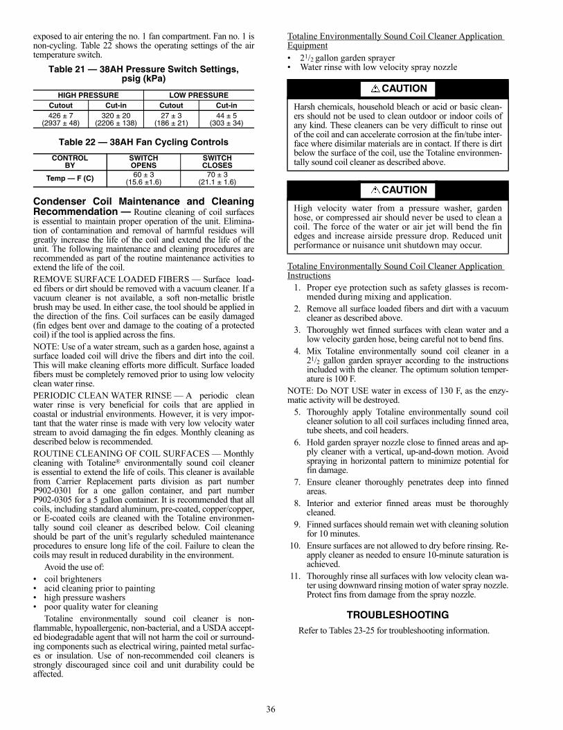
36
exposed to air entering the no. 1 fan compartment. Fan no. 1 isnon-cycling. Table 22 shows the operating settings of the airtemperature switch.
Table 21 — 38AH Pressure Switch Settings,psig (kPa)
Table 22 — 38AH Fan Cycling Controls
Condenser Coil Maintenance and CleaningRecommendation — Routine cleaning of coil surfacesis essential to maintain proper operation of the unit. Elimina-tion of contamination and removal of harmful residues willgreatly increase the life of the coil and extend the life of theunit. The following maintenance and cleaning procedures arerecommended as part of the routine maintenance activities toextend the life of the coil.REMOVE SURFACE LOADED FIBERS — Surface load-ed fibers or dirt should be removed with a vacuum cleaner. If avacuum cleaner is not available, a soft non-metallic bristlebrush may be used. In either case, the tool should be applied inthe direction of the fins. Coil surfaces can be easily damaged(fin edges bent over and damage to the coating of a protectedcoil) if the tool is applied across the fins.NOTE: Use of a water stream, such as a garden hose, against asurface loaded coil will drive the fibers and dirt into the coil.This will make cleaning efforts more difficult. Surface loadedfibers must be completely removed prior to using low velocityclean water rinse.PERIODIC CLEAN WATER RINSE — A periodic cleanwater rinse is very beneficial for coils that are applied incoastal or industrial environments. However, it is very impor-tant that the water rinse is made with very low velocity waterstream to avoid damaging the fin edges. Monthly cleaning asdescribed below is recommended.ROUTINE CLEANING OF COIL SURFACES — Monthlycleaning with Totaline® environmentally sound coil cleaneris essential to extend the life of coils. This cleaner is availablefrom Carrier Replacement parts division as part numberP902-0301 for a one gallon container, and part numberP902-0305 for a 5 gallon container. It is recommended that allcoils, including standard aluminum, pre-coated, copper/copper,or E-coated coils are cleaned with the Totaline environmen-tally sound coil cleaner as described below. Coil cleaningshould be part of the unit’s regularly scheduled maintenanceprocedures to ensure long life of the coil. Failure to clean thecoils may result in reduced durability in the environment.
Avoid the use of:• coil brighteners• acid cleaning prior to painting• high pressure washers• poor quality water for cleaning
Totaline environmentally sound coil cleaner is non-flammable, hypoallergenic, non-bacterial, and a USDA accept-ed biodegradable agent that will not harm the coil or surround-ing components such as electrical wiring, painted metal surfac-es or insulation. Use of non-recommended coil cleaners isstrongly discouraged since coil and unit durability could beaffected.
Totaline Environmentally Sound Coil Cleaner Application Equipment• 21/2 gallon garden sprayer• Water rinse with low velocity spray nozzle
Totaline Environmentally Sound Coil Cleaner Application Instructions
1. Proper eye protection such as safety glasses is recom-mended during mixing and application.
2. Remove all surface loaded fibers and dirt with a vacuumcleaner as described above.
3. Thoroughly wet finned surfaces with clean water and alow velocity garden hose, being careful not to bend fins.
4. Mix Totaline environmentally sound coil cleaner in a21/2 gallon garden sprayer according to the instructionsincluded with the cleaner. The optimum solution temper-ature is 100 F.
NOTE: Do NOT USE water in excess of 130 F, as the enzy-matic activity will be destroyed.
5. Thoroughly apply Totaline environmentally sound coilcleaner solution to all coil surfaces including finned area,tube sheets, and coil headers.
6. Hold garden sprayer nozzle close to finned areas and ap-ply cleaner with a vertical, up-and-down motion. Avoidspraying in horizontal pattern to minimize potential forfin damage.
7. Ensure cleaner thoroughly penetrates deep into finnedareas.
8. Interior and exterior finned areas must be thoroughlycleaned.
9. Finned surfaces should remain wet with cleaning solutionfor 10 minutes.
10. Ensure surfaces are not allowed to dry before rinsing. Re-apply cleaner as needed to ensure 10-minute saturation isachieved.
11. Thoroughly rinse all surfaces with low velocity clean wa-ter using downward rinsing motion of water spray nozzle.Protect fins from damage from the spray nozzle.
TROUBLESHOOTINGRefer to Tables 23-25 for troubleshooting information.
HIGH PRESSURE LOW PRESSURECutout Cut-in Cutout Cut-in426 ± 7 320 ± 20 27 ± 3 44 ± 5
(2937 ± 48) (2206 ± 138) (186 ± 21) (303 ± 34)
CONTROLBY
SWITCHOPENS
SWITCHCLOSES
Temp — F (C) 60 ± 3(15.6 ±1.6)
70 ± 3(21.1 ± 1.6)
CAUTION
Harsh chemicals, household bleach or acid or basic clean-ers should not be used to clean outdoor or indoor coils ofany kind. These cleaners can be very difficult to rinse outof the coil and can accelerate corrosion at the fin/tube inter-face where disimilar materials are in contact. If there is dirtbelow the surface of the coil, use the Totaline environmen-tally sound coil cleaner as described above.
CAUTION
High velocity water from a pressure washer, gardenhose, or compressed air should never be used to clean acoil. The force of the water or air jet will bend the finedges and increase airside pressure drop. Reduced unitperformance or nuisance unit shutdown may occur.

37
Table 23 — 38AKS Units Troubleshooting
SYMPTOM AND PROBABLE CAUSE PROBABLE REMEDY
COMPRESSOR DOES NOT RUN1. Control circuit breaker tripped.2. Power line open.3. Oil pressure switch tripped.4. Safety device tripped.5. Contactor stuck open.6. Loose terminal connection.7. Improperly wired controls.8. Seized compressor.
9. Low line voltage.
10. Compressor motor defective.
1. Reset control circuit breaker.2. Reset circuit breaker.3. Reset oil pressure switch at unit.4. Reset control circuit with thermostat.5. Replace contactor.6. Check connections.7. Check and rewire.8. Check motor winding for open or short.
Replace compressor, if necessary.9. Check line voltage — determine location of
voltage drop and remedy deficiency.10. Check motor winding for open or short.
Replace compressor, if necessary.
COMPRESSOR STOPS ON LOW-PRESSURE CONTROL1. Compressor suction shutoff valve partially closed.2. Low refrigerant charge.3. Liquid line solenoid valve(s) fails to open.
4. Liquid line shutoff valve closed.
1. Open valve.2. Add refrigerant.3. Check liquid line solenoid valve for proper
operation. Replace if necessary.4. Open valve.
COMPRESSOR STOPS ON HIGH-PRESSURE CONTROL1. Compressor discharge valve partially closed.2. Air in system.3. Condenser fan(s) not operating.4. System is overcharged.
1. Open valve or replace if defective.2. Purge and evacuate system.3. Check motor wiring and repair or replace if defective.4. Reclaim charge as needed.
UNIT OPERATES TOO LONG OR CONTINUOUSLY1. Low refrigerant charge.2. Control contacts fused.3. Air in system.4. Partially plugged expansion valve or filter drier.
1. Add refrigerant.2. Replace control.3. Purge and evacuate system.4. Clean or replace.
SYSTEM IS NOISY1. Piping vibration.2. Compressor noisy.
1. Support piping as required.2. Check valve plates for valve noise. Replace
compressor if bearings are worn.
COMPRESSOR LOSES OIL1. Leak in system.2. Crankcase heaters not energized during shutdown.3. Improper interconnecting piping design.
1. Repair leak.2. Check wiring and relays. Check heater and replace if defective.3. Check piping for oil return. Replace if necessary.
FROSTED SUCTION LINEExpansion valve admitting excess refrigerant. Adjust expansion valve.
HOT LIQUID LINE1. Shortage of refrigerant due to leak.2. Expansion valve opens too wide.
1. Repair leak and recharge.2. Adjust expansion valve.
FROSTED LIQUID LINERestricted filter drier. Remove restriction or replace.
COMPRESSOR WILL NOT UNLOAD1. Defective unloader.2. Defective capacity control solenoid valve.3. Miswired liquid line solenoid.4. Weak, broken, or wrong valve body spring.
1. Replace.2. Replace valve.3. Rewire correctly.4. Replace spring.
COMPRESSOR WILL NOT LOAD1. Miswired capacity control liquid solenoid.2. Defective capacity control solenoid valve.3. Plugged strainer (high side).4. Struck or damaged unloader piston or piston ring(s).
1. Rewire correctly.2. Replace valve.3. Clean or replace strainer.4. Clean or replace the necessary parts.

38
Table 24 — 38AH Units Troubleshooting
PROBLEM SOLUTION
COMPRESSOR DOES NOT RUN
Contactor Open
1. Power off. 1. Restore power.2. Fuses blown in field power circuit. 2. After finding cause and correcting, replace with correct size fuse.3. No control power. 3. Check secondary fuse(s); replace with correct type and size. Replace trans-
former if primary winding is receiving power.4. Thermostat circuit open. 4. Check thermostat setting.5. Compressor circuit breaker tripped. 5. Check for excessive compressor current draw. Reset breaker; replace if
defective.6. Safety device lockout circuit active. 6. Reset lockout circuit at thermostat or circuit breaker.7. Oil pressure switch tripped. 7. See Compressor Stops on Oil Pressure Switch section on page 39.8. Low-pressure switch open. 8. Check for refrigerant undercharge, obstruction of indoor airflow, or whether com-
pressor suction shutoff valve is fully open. Make sure liquid line solenoid valve(s) is open. See Compressor Stops on Low-Pressure Switch section below.
9. High-pressure switch open. 9. Check for refrigerant overcharge, obstruction of outdoor airflow, air in system, or whether compressor discharge valve is fully open. Be sure outdoor fans are operating correctly. See Compressor Stops on High-Pressure Switch section below.
10. Compressor overtemperature switch open. 10. Check for open condition. Allow for reset. Replace if defective.11. Loose electrical connections. 11. Tighten all connections.12. Compressor stuck. 12. See 06D compressor service literature.
Contactor Closed
1. Compressor leads loose. 1. Check connections.2. Motor windings open. 2. See 06D compressor service literature.3. Single phasing. 3. Check for blown fuse. Check for loose connection at compressor terminal.
COMPRESSOR STOPS ON HIGH-PRESSURE SWITCH
Outdoor Fan On
1. High-pressure switch faulty. 1. Replace switch.2. Reversed fan rotation. 2. Confirm rotation, correct if necessary.3. Airflow restricted. 3. Remove obstruction.4. Air recirculating. 4. Clear airflow area.5. Noncondensables in system. 5. Recover refrigerant and recharge as required.6. Refrigerant overcharge. 6. Recover refrigerant as required.7. Line voltage incorrect. 7. Consult power company.8. Refrigerant system restrictions. 8. Check or replace filter drier, expansion valve, etc. Check that compressor dis-
charge service valve is fully open.
Outdoor Fan Off
1. Fan slips on shaft. 1. Tighten fan hub setscrews.2. Motor not running. 2. Check power and capacitor.3. Motor bearings stuck. 3. Replace bearings.4. Motor overload open. 4. Check overload rating. Check for fan blade obstruction.5. Motor burned out. 5. Replace motor.
COMPRESSOR STOPS ON LOW-PRESSURESWITCH
Indoor-Air Fan Running
1. Compressor suction service valve partially closed. 1. Open valve fully.2. Liquid line solenoid valve(s) fails to open. 2. Check liquid line solenoid valve(s) for proper operation. Replace if necessary.3. Filter drier plugged. 3. Replace filter drier.4. Expansion valve power head defective. 4. Replace power head.5. Low refrigerant charge. 5. Add charge. Check low-pressure switch setting.

39
Table 24 — 38AH Units Troubleshooting (cont)
PROBLEM SOLUTION
COMPRESSOR STOPS ON LOW-PRESSURE SWITCH (cont)
Airflow Restricted
1. Coil iced up. 1. Check refrigerant charge.2. Coil dirty. 2. Clean coil fins.3. Air filters dirty. 3. Clean or replace filters.4. Dampers closed. 4. Check damper operation and position.
Indoor-Air Fan Stopped
1. Electrical connections loose. 1. Tighten all connections.2. Fan relay defective. 2. Replace relay.3. Motor overload open. 3. Check power supply.4. Motor defective. 4. Replace motor.5. Fan belt broken or slipping. 5. Replace or tighten belt.
COMPRESSOR STOPS ON OIL PRESSURE SWITCH
1. Oil level too low or too high. 1. Check oil level requirements; adjust oil level until within view of sight glass when running.
2. Compressor is short cycling. 2. Check fora. Thermostat location and operation.b. Safety device lockout circuit operation.c. Low-pressure switch operation.
3. Crankcase heater off. 3. Check relay operation; replace crankcase heater(s), if defective.4. Low refrigerant charge. 4. Adjust charge as required.5. Refrigerant floodback. 5. Adjust TXV (thermostatic expansion valve) superheat.6. Evaporator coil is blocked or iced. 6. Check and correct as required.7. Evaporator fan not operating. 7. Check and correct as required.8. Distributor and/or TXV too large. 8. Check sizing at design conditions; change if incorrect for current application.9. Suction riser too large. 9. Check line sizing at minimum design condition; change piping if incorrect.
10. Defective oil pressure switch. 10. Check switch for proper operation; check capillary lines for plugged lines.11. Plugged oil pump inlet screen. 11. Clean oil pump screen.12. Faulty oil pump drive segment. 12. Replace drive segment.13. Worn oil pump. 13. Replace bearing head assembly.14. Worn compressor bearings. 14. Replace compressor; see 06D service instructions.15. Accumulator external oil return line is plugged. 15. Remove and unplug oil return line.
COMPRESSOR RUNNING BUT COOLINGINSUFFICIENT
Suction Pressure Low
1. Refrigerant charge low. 1. Add refrigerant.2. Head pressure low. 2. Check refrigerant charge. Check outdoor-air fan thermostat settings.3. Air filters dirty. 3. Clean or replace filters.4. Expansion valve power head defective. 4. Replace power head.5. Indoor coil partially iced. 5. Check low-pressure setting.6. Indoor airflow restricted. 6. Remove obstruction.
Suction Pressure High
1. Unloaders not functioning. 1. Check unloader adjustments. Check unloader setting.2. Compressor valve defective. 2. See 06D compressor service literature.3. Heat load excessive. 3. Check for open doors or windows in vicinity of fan coil.

40
Table 24 — 38AH Units Troubleshooting (cont)
Table 25 — Control Module (CM) Troubleshooting
LEGEND
*Multiple blinks are a series of on/off flashes of equal duration followed by 1 second off.
PROBLEM SOLUTION
UNIT OPERATES TOO LONG OR CONTINUOUSLY1. Low refrigerant charge. 1. Add refrigerant.2. Control contacts fused. 2. Replace control.3. Air in system. 3. Purge and evacuate system.4. Partially plugged expansion valve or filter drier. 4. Clean or replace.
SYSTEM IS NOISY1. Piping vibration. 1. Support piping as required.2. Compressor noisy. 2. Check valve plates for valve noise. Replace compressor if bearings
are worn.
COMPRESSOR LOSES OIL1. Leak in system. 1. Repair leak.2. Crankcase heaters not energized during shutdown. 2. Check wiring and relays. Check heater and replace if defective.3. Improper interconnecting piping design. 3. Check piping for oil return. Replace if necessary.
FROSTED SUCTION LINEExpansion valve admitting excess refrigerant. Adjust expansion valve.
HOT LIQUID LINE1. Shortage of refrigerant due to leak. 1. Repair leak and recharge.2. Expansion valve opens too wide. 2. Adjust expansion valve.
FROSTED LIQUID LINE1. Restricted filter drier. 1. Remove restriction or replace.2. Liquid line solenoid valve partially closed. 2. Replace valve.
COMPRESSOR WILL NOT UNLOAD1. Defective unloader. 1. Replace unloader.2. Defective capacity control solenoid valve (if used). 2. Replace valve.3. Miswired capacity control liquid line solenoid (if used). 3. Rewire correctly.4. Weak, broken, or wrong valve body spring. 4. Replace spring.
COMPRESSOR WILL NOT LOAD1. Miswired capacity control liquid line solenoid (if used). 1. Rewire correctly.2. Defective capacity control solenoid valve (if used). 2. Replace valve.3. Plugged strainer (high side). 3. Clean or replace strainer.4. Stuck or damaged unloader piston or piston ring(s). 4. Clean or replace the necessary parts.
LED NO. OFBLINKS*
TIME (Seconds)STATUS
On Off
DS1 Power LED 1—
1/4Steady
1/4—
Normal operationLockout state
DS2 Alarm LED
—123
Steady1/41/41/4
—111
HPS or COTP openLPS openOPS openLPS and OPS open
DS3 Status LED——1
—Steady
1/4
Steady—1/4
No call for coolingCooling3 minute compressor delay
DS4 “K1” LED — Steady — Relay K1 closed
COTP — Compressor Overtemperature ProtectionHPS — High-Pressure SwitchLED — Light-Emitting DiodeLPS — Low-Pressure SwitchOPS — Oil Pressure Switch


Manufacturer reserves the right to discontinue, or change at any time, specifications or designs without notice and without incurring obligations.Catalog No. 04-53380005-01 Printed in U.S.A. Form 38A-21SI Pg 42 612 3-09 Replaces: 38A-17SI
Copyright 2009 Carrier Corporation

Manufacturer reserves the right to discontinue, or change at any time, specifications or designs without notice and without incurring obligations.PC 111 Catalog No. 536-203 Printed in U.S.A. Form 62AQ-1SI Pg CL-1 7-99 Replaces: NewBook 1 1 1 4 4 4
Tab 1a 1b 5a 5a 6a 6b
CL-1
START-UP CHECKLIST
I. PRELIMINARY INFORMATION
OUTDOOR: MODEL NO. SERIAL NO.
INDOOR: AIR HANDLER MANUFACTURER
MODEL NO. SERIAL NO.
ADDITIONAL ACCESSORIES
II. PRE-START-UPOUTDOOR UNIT
IS THERE ANY SHIPPING DAMAGE? (Y/N)
IF SO, WHERE:
WILL THIS DAMAGE PREVENT UNIT START-UP? (Y/N)
CHECK POWER SUPPLY. DOES IT AGREE WITH UNIT? (Y/N)
HAS THE GROUND WIRE BEEN CONNECTED? (Y/N)
HAS THE CIRCUIT PROTECTION BEEN SIZED AND INSTALLED PROPERLY? (Y/N)
ARE THE POWER WIRES TO THE UNIT SIZED AND INSTALLED PROPERLY? (Y/N)
HAVE COMPRESSOR HOLDDOWN BOLTS BEEN LOOSENED (Snubber washers are snug, but not tight)?(Y/N)
CONTROLS
HAVE THERMOSTAT AND INDOOR FAN CONTROL WIRINGCONNECTIONS BEEN MADE AND CHECKED? (Y/N)
ARE ALL WIRING TERMINALS (including main power supply) TIGHT? (Y/N)
HAVE CRANKCASE HEATER(S) BEEN ENERGIZED FOR 24 HOURS? (Y/N)
INDOOR UNIT
HAS WATER BEEN PLACED IN DRAIN PAN TO CONFIRM PROPER DRAINAGE? (Y/N)
ARE PROPER AIR FILTERS IN PLACE? (Y/N)
HAVE FAN AND MOTOR PULLEYS BEEN CHECKED FOR PROPER ALIGNMENT? (Y/N)
DO THE FAN BELTS HAVE PROPER TENSION? (Y/N)
HAS CORRECT FAN ROTATION BEEN CONFIRMED? (Y/N)
PIPING
ARE LIQUID LINE SOLENOID VALVES LOCATED AT THE EVAPORATOR COILS AS REQUIRED? (Y/N)
HAVE LEAK CHECKS BEEN MADE AT COMPRESSORS, CONDENSERS, EVAPORATORS,TXVs (thermostatic expansion valves), SOLENOID VALVES, FILTER DRIERS, AND FUSIBLE PLUGSWITH A LEAK DETECTOR? (Y/N)
LOCATE, REPAIR, AND REPORT ANY LEAKS.
HAVE ALL COMPRESSOR SERVICE VALVES BEEN FULLY OPENED (BACKSEATED)? (Y/N)
HAVE LIQUID LINE SERVICE VALVES BEEN OPENED? (Y/N)

Manufacturer reserves the right to discontinue, or change at any time, specifications or designs without notice and without incurring obligations.Catalog No. 04-53380005-01 Printed in U.S.A. Form 38A-21SI Pg CL-2 612 3-09 Replaces: 38A-17SI
Copyright 2009 Carrier Corporation
- -
- -
- -
- -
- -
- -
- -
- -
- -
- -
- -
- -
- -
- -
- -
- -
- -
- -
- -
- -
- -
- -
- -
- -
- -
- -
- -
- -
- -
- -
- -
- -
- -
- -
- -
- -
- -
- -
- -
- -
- -
- -
- -
- -
- -
- -
- -
- -
- -
- -
- -
- -
- -
- -
- -
- -
- -
- -
- -
- -
- -
- -
- -
- -
- -
- -
- -
- -
- -
- -
- -
- -
- -
- -
- -
- -
- -
- -
- -
- -
- -
- -
- -
- -
- -
- -
- --
- -
- -
- -
- -
- -
- -
- -
- -
- -
-
CU
T A
LON
G D
OT
TE
D L
INE
CU
T A
LON
G D
OT
TE
D L
INE
CHECK VOLTAGE IMBALANCE
LINE-TO-LINE VOLTS: AB V AC V BC V
(AB + AC + BC)/3 = AVERAGE VOLTAGE = V
MAXIMUM DEVIATION FROM AVERAGE VOLTAGE = V
VOLTAGE IMBALANCE = 100 X (MAX DEVIATION)/(AVERAGE VOLTAGE) = %
IF OVER 2% VOLTAGE IMBALANCE, DO NOT ATTEMPT TO START SYSTEM!CALL LOCAL POWER COMPANY FOR ASSISTANCE.
III. START-UP
CHECK EVAPORATOR FAN SPEED AND RECORD.
CHECK CONDENSER FAN SPEED AND RECORD.
AFTER AT LEAST 10 MINUTES RUNNING TIME, RECORD THE FOLLOWING MEASUREMENTS:
COMP A1 COMP B1 (38AH Unit Only)
OIL PRESSURESUCTION PRESSURESUCTION LINE TEMPDISCHARGE PRESSUREDISCHARGE LINE TEMPENTERING CONDENSER AIR TEMPLEAVING CONDENSER AIR TEMPEVAP ENTERING-AIR DB (dry bulb) TEMPEVAP ENTERING-AIR WB (wet bulb) TEMPEVAP LEAVING-AIR DB TEMPEVAP LEAVING-AIR WB TEMPCOMPRESSOR AMPS (L1/L2/L3) / / / /
CHECK THE COMPRESSOR OIL LEVEL SIGHT GLASSES; ARE THE SIGHT GLASSES SHOWINGOIL LEVEL IN VIEW? (Y/N)
NOTES: