
GE Consumer & Industrial Power Quality - PT. …suryamas-ep.com/download/GE-ZTS Series...
8
GE Consumer & Industrial Power Quality ZTS Series Low-Voltage Automatic Transfer Switches
Transcript of GE Consumer & Industrial Power Quality - PT. …suryamas-ep.com/download/GE-ZTS Series...
GE Consumer & IndustrialPower Quality
ZTS SeriesLow-Voltage Automatic Transfer Switches
PB-5066 • Page 2
Since its introduction, the GE ZenithZTS Series of transfer switches hasbecome a hallmark of quality andperformance. Reliability resultingfrom superior design and heavyduty construction has made theZTS the industry standard for criti-cal installations. Our emphasis onresearch and development, designimprovements, materials, manu-
facturing methods, quality assurance, and serviceyields products that have been proven in hundredsof thousands of applications.
Subsequent to the first ZTS units installed, our engi-neering staff has been dedicated to the improvementand expansion of our line. Today, GE Zenith offersthe widest selection of transfer switch productsworldwide.
• ZTS Automatic Transfer Switches 40-4000 Amps
• ZTSD Delayed Transition Transfer Switches40-4000 Amps
• ZTSCT Closed Transition Transfer Switches100-4000 Amps
• ZBTS Automatic Transition Bypass Switches100-4000 Amps
• ZBTSD Delayed Transition Bypass Switches100-4000 Amps
• ZBTSCT Closed Transition Bypass Switches100-4000 Amps
All ZTS products meet or exceed industry requirementsallowing specification and installation confidence.
• UL 1008 listed through 480 VAC
• CSA C22.2 No. 178 listed through 600 VAC
• IEC 947-6-1 listed through 480 VAC
• Codes and Standards
� NFPA 70, 99, 101, 110
� IEEE 446, 241, 602
� NEC 517, 700, 701, 702
� NEMA ICS-10
• Controls tested in accordance with:
� IEEE 472 (ANSI C37.90A)
� EN55022 Class B (CISPR 22)(Exceeds EN55011 & MILSTD 461 Class 3)
� EN61000-4-2 Class B (Level 4)
� EN61000-4-3 (ENV50140) 10 v/m
� EN61000-4-4
� EN61000-4-5, IEEE C62.41 (1.2 X 50μs, 0.5 to 4 kV)
� EN61000-4-6 (ENV50141)
� EN61000-4-11
• Enclosures meet the requirements of:
� UL 508, 50
� ANSI C33.76
� ICS 6
� NEMA 250
• Quality System
� ISO 9001 Registered
Specification Assistance
GE Zenith offers a complete range of product guide specifications to help you determine your needs.
For more information, please consult your local GE Zenith representative, our factory or our website at www.geindustrial.com/ats.
user
Highlight
user
Highlight
user
Highlight
user
Highlight
user
Highlight
user
Highlight
ZTS Series Automatic Transfer Switches
Universal MotorDisconnect (UMD):This load control discon-nects a large motor viaits control circuit for anadjustable period of timeprior to transfer in eitherdirection. For switchingmultiple motors, GE ZenithAccessory A62 discon-nects the motors priorto transfer and bringsthem back on linesequentially.
Accessory R50: This isan in-phase monitorthat compares the phaseangle between bothsources of power andprevents transfer untilthe two are approximately
in phase (within a self-adjusting range). GE Zenith’shigh speed transferaction, coupled with theMX series microprocessorcontrol logic, ensure closures at or near zerodegree phase difference.
Series ZTSD: GE Zenithoffers delayed transitionswitching on transferswitches rated 40 amperesand above – the GE ZenithZTSD Series. This pro-grammed center-offposition allows for thefull decay of rotatingmotors or transformerfields. It can also beused for load sheddingof selected circuits or
other applications whichrequire a means to dis-connect the load fromeither source. Major UPSsystem manufacturersrecommend delayedtransition switches forproper restart sequencingof their systems.
Series ZTSCT: GE Zenith’sseries of closed transitionswitches combine ZTSDoperation during a sourcefailure with a highlyengineered control systemthat allows momentaryparalleling (100 ms) oftwo acceptable sources,thereby limiting theimpact of transfer on the load.
Electrical Ratings
• Ratings 40 to 4000 amperes
• 2, 3 or 4 Poles
• Open type, NEMA 1, 3R, 4, 4X and 12
• Available to 600 VAC, 50 or 60 Hz
• Suitable for emergency and standbyapplications on all classes of load, 100% tungsten rated through 400 amps
• UL 1008 listed at 480 VAC
• CSA C22.2 No. 178 certified at 600 VAC
• IEC 947-6-1 listed at 480 VAC
Performance Features
• Contact transfer speed less than 100 milliseconds
• High close-in and withstand capability
• Temperature rise test per UL 1008conducted after overload and endurancetests - exceeds UL requirements
• Available in ZTS (utility-generator), ZTSU(utility-utility), ZTSG (generator-generator)and ZTSM (manual) configurations
Design and Construction Features
• Double throw, interlocked operation
• Electrically operated, mechanically heldby a simple, over-center mechanism
• Segmented silver tungsten alloy contacts with separate arcing contacts on 225 amp and above
• Arc quenching grids, enclosed arcchambers, and wide contact air gap for superior source-to-source isolationon all units
• Control circuit disconnect plug anddrive inhibit switch for safe maintenance
• Components accessible for inspectionand maintenance without removal ofthe switch or power conductors
• Mechanical indicator and contactchamber cover designed for inspection,safety and position designation
Page 3 • PB-5066
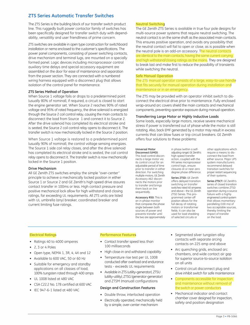
The ZTS Series is the building block of our transfer switch productline. This ruggedly built power contactor family of switches hasbeen specifically designed for transfer switch duty with depend-ability, versatility and user friendliness of prime concern.
ZTS switches are available in open type construction for switchboardinstallation or nema enclosed to the customer’s specifications. Thepower panel components, consisting of power switching contacts,drive mechanism and terminal lugs, are mounted on a speciallyformed panel. Logic devices including microprocessor controlauxiliary time delays and special accessory equipment areassembled on the door for ease of maintenance and separationfrom the power section. They are connected with a numberedwiring harness equipped with a disconnect plug that allows isolation of the control panel for maintenance.
ZTS Series Method of OperationWhen Source 1 voltage fails or drops to a predetermined point(usually 80% of nominal), if required, a circuit is closed to startthe engine generator set. When Source 2 reaches 90% of ratedvoltage and 95% of rated frequency, the drive solenoid is energizedthrough the Source 2 coil control relay, causing the main contacts todisconnect the load from Source 1 and connect it to Source 2.After the drive solenoid has completed its electrical stroke and is seated, the Source 2 coil control relay opens to disconnect it. Thetransfer switch is now mechanically locked in the Source 2 position.
When Source 1 voltage is restored to a predetermined point (usually 90% of nominal), the control voltage sensing energizes.The Source 1 side coil relay closes, and after the drive solenoidhas completed its electrical stroke and is seated, the coil controlrelay opens to disconnect it. The transfer switch is now mechanicallylocked in the Source 1 position.
Drive MechanismAll GE Zenith ZTS switches employ the simple “over-center” principle to achieve a mechanically locked position in eitherSource 1 or Source 2 and GE Zenith’s high speed drive assurescontact transfer in 100ms or less. High contact pressure andpositive mechanical lock allow for high withstand and closingratings, far exceeding UL requirements. All ZTS units are listedwith UL umbrella (any) breaker, coordinated breaker and current limiting fuse ratings.
Neutral SwitchingThe GE Zenith ZTS Series is available in true four pole designs formulti-source power systems that require neutral switching. Theneutral contact is on the same shaft as the associated main contacts.This ensures positive operation, and avoids any possibility thatthe neutral contact will fail to open or close, as is possible whenthe neutral pole is an add-on accessory. The neutral contactsare identical to the main contacts, having the same current carryingand high withstand/closing ratings as the mains. They are designedto break last and make first to reduce the possibility of transientswhile switching the neutral.
Safe Manual OperationThe ZTS manual operator consists of a large, easy-to-use handlethat fits securely for manual operation during installation andmaintenance or in an emergency.
The ZTS may be provided with an operator inhibit switch to dis-connect the electrical drive prior to maintenance. Fully enclosedwrap-around arc covers shield the main contacts and mechanicalcomponents, preventing operator exposure during manual operation.
Transferring Large Motor or Highly Inductive LoadsSome loads, especially large motors, receive severe mechanicalstress if power is transferred out of phase while the motor is stillrotating. Also, back EMF generated by a motor may result in excesscurrents that can blow fuses or trip circuit breakers. GE Zenithoffers four solutions to these problems:
user
Highlight
user
Highlight
user
Highlight
user
Highlight
user
Highlight
user
Highlight
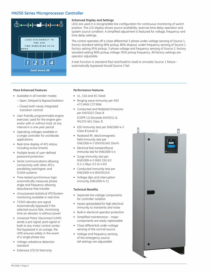
Enhanced Display and SettingsLEDs are used in a recognizable line configuration for continuous monitoring of switchposition. The LCD display shows source availability, exercise time delay operation andsystem source condition. A simplified adjustment is featured for voltage, frequency andtime delay settings.
The control operates off a close differential 3-phase under-voltage sensing of Source 1,factory standard setting 90% pickup, 80% dropout; under-frequency sensing of Source 1factory setting 95% pickup; 3-phase voltage and frequency sensing of Source 2, factorystandard setting 90% pickup voltage, 95% pickup frequency. All factory settings areoperator adjustable.
A test function is standard (fast test/load/no load) to simulate Source 1 failure - automatically bypassed should Source 2 fail.
Entelli-Switch 250
M O R E
L O A D D I S C O N N E C T T D
P R E X F R
T I M E R E M A I N I N G 0 4 : 0 2
MX250 Series Microprocessor Controller
PB-5066 • Page 4
More Enhanced Features
• Available in all transfer modes:
~ Open, Delayed & Bypass/Isolation
~ Closed (with newly integrated transition control)
• User-friendly programmable engineexerciser, used for the engine gen-erator with or without load, at anyinterval in a one-year period
• Operating voltages available in a single controller for worldwideapplications
• Real-time display of ATS status, including active timer(s)
• Multiple levels of user-defined password protection
• Serial communications allowingconnectivity with other ATS's, paralleling switchgear, and SCADA systems
• Time-tested synchronous logicautomatically measures phaseangle and frequency allowing disturbance-free transfer
• Unsurpassed statistical ATS/Systemmonitoring available in real-time
• T3/W3 elevator pre-signal.Automatically bypassed if theselected source fails, minimizingtime an elevator is without power
• Universal Motor Disconnect (UMD)sends a pre-signal, post-signal or both to any motor control center. Not bypassed in an outage, theUMD ensures safety in the event of a single phase loss
• Voltage unbalance detection standard
• Extensive 2/5/10 Warranty
Technical Benefits
• Separate line voltage componentsfor controller isolation
• Inputs optoisolated for high electricalimmunity to transients and noise
• Built-in electrical operator protection
• Simplified maintenance – majorcomponents are easily replaceable
• Close differential under-voltagesensing of the normal source
• Voltage and frequency sensing of the emergency source (all settings are adjustable)
Performance Features
• UL, CSA and IEC listed
• Ringing wave immunity per IEEE472 (ANSI C37.90A)
• Conducted and Radiated Emissionsper EN55022 Class B
(CISPR 11) (Exceeds EN55011 & MILSTD 461 Class 3)
• ESD Immunity test per EN61000-4-2Class B (Level 4)
• Radiated RF, electromagnetic field immunity test per EN61000-4-3 (ENV50140) 10v/m
• Electrical fast transient/burst immunity test for EN61000-4-4
• Surge immunity test per EN61000-4-5 (IEEE C62.41)(1.2 x 50μs, 0.5 to 4 kV)
• Conducted immunity test perEN61000-4-6 (ENV50141)
• Voltage dips and interruptionimmunity EN61000-4-11
Accessories
6P
A1
A1E
A3
A4
Calibrate
CDT
CDP
**DS
*DT
*DW
E
EL/P
K/P
L1
L2
L3
L4
*LNP
P1
Q2
Q3
Q7
R1-1
R1-3
R15
*R15D
R16
R50
S5P
S12P
S13P
T
T3/W3
U
UMD
VI
W
YEN
MSTD MEXE MCON MSEN MSPE MPSG
2
2
2
2
2
2
2
2
3
3
2
2
2
2
2
2
2
2
2
2
2
2
Group Packages
22
3
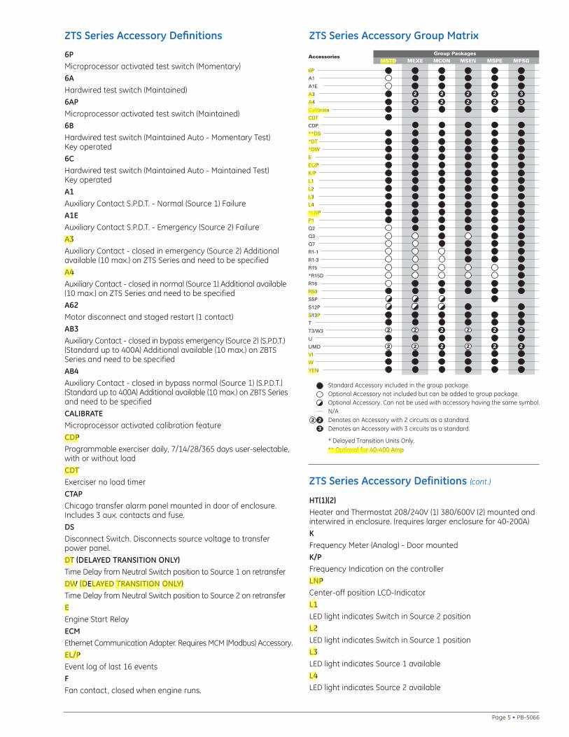
Standard Accessory included in the group package.Optional Accessory not included but can be added to group package.Optional Accessory. Can not be used with accessory having the same symbol.N/ADenotes an Accessory with 2 circuits as a standard.Denotes an Accessory with 3 circuits as a standard.
* Delayed Transition Units Only.** Optional for 40-400 Amp
Page 5 • PB-5066
ZTS Series Accessory Group MatrixZTS Series Accessory Definitions
6PMicroprocessor activated test switch (Momentary)6AHardwired test switch (Maintained)6APMicroprocessor activated test switch (Maintained)6BHardwired test switch (Maintained Auto - Momentary Test) Key operated6CHardwired test switch (Maintained Auto - Maintained Test) Key operatedA1Auxiliary Contact S.P.D.T. - Normal (Source 1) FailureA1EAuxiliary Contact S.P.D.T. - Emergency (Source 2) FailureA3Auxiliary Contact - closed in emergency (Source 2) Additionalavailable (10 max.) on ZTS Series and need to be specifiedA4Auxiliary Contact - closed in normal (Source 1) Additional available(10 max.) on ZTS Series and need to be specifiedA62Motor disconnect and staged restart (1 contact)AB3Auxiliary Contact - closed in bypass emergency (Source 2) (S.P.D.T.)(Standard up to 400A) Additional available (10 max.) on ZBTSSeries and need to be specifiedAB4Auxiliary Contact - closed in bypass normal (Source 1) (S.P.D.T.)(Standard up to 400A) Additional available (10 max.) on ZBTS Seriesand need to be specifiedCALIBRATEMicroprocessor activated calibration featureCDPProgrammable exerciser daily, 7/14/28/365 days user-selectable,with or without loadCDTExerciser no load timerCTAPChicago transfer alarm panel mounted in door of enclosure.Includes 3 aux. contacts and fuse.DSDisconnect Switch. Disconnects source voltage to transferpower panel.DT (DELAYED TRANSITION ONLY)Time Delay from Neutral Switch position to Source 1 on retransferDW (DELAYED TRANSITION ONLY)Time Delay from Neutral Switch position to Source 2 on retransferEEngine Start RelayECMEthernet Communication Adapter. Requires MCM (Modbus) Accessory.EL/PEvent log of last 16 eventsFFan contact, closed when engine runs.
HT(1)(2)Heater and Thermostat 208/240V (1) 380/600V (2) mounted andinterwired in enclosure. (requires larger enclosure for 40-200A)KFrequency Meter (Analog) - Door mountedK/PFrequency Indication on the controllerLNPCenter-off position LCD-IndicatorL1LED light indicates Switch in Source 2 positionL2LED light indicates Switch in Source 1 positionL3LED light indicates Source 1 availableL4LED light indicates Source 2 available
ZTS Series Accessory Definitions (cont.)
user
Highlight
user
Highlight
user
Highlight
user
Highlight
user
Highlight
user
Highlight
user
Highlight
user
Highlight
user
Highlight
user
Highlight
user
Highlight
user
Highlight
user
Highlight
user
Highlight
user
Highlight
user
Highlight
user
Highlight
user
Highlight
user
Highlight
user
Highlight
user
Highlight
user
Highlight
user
Highlight
user
Highlight
user
Highlight
user
Highlight
user
Highlight
user
Highlight
user
Highlight
user
Highlight
user
Highlight
user
Highlight
user
Highlight
user
Highlight
user
Highlight
user
Highlight
user
Highlight
user
Highlight
user
Highlight
user
Highlight
user
Highlight
user
Highlight
user
Highlight

LCM
LonWorks Communication Module
M1Single Phase Amp Meter (Analog)
M2Three Phase Amp Meter (Analog)
M90EPM2000 True RMS Digital Meter with display (Amps, Volts, Power,Energy, Power Factory and Frequency). 3 Line LED Display. 50/60 HzUniversal Operation. 1 or 3 phase. Standard Modbus RTU RS485communications capability. 40 - 1200 Amps.
M90A
Adds Pre-Wiring for Enervista Viewpoint Monitoring of M90Accessory & ATS Status using Modbus RS485 Serial Communications
M90B
Adds Pre-Wiring for Enervista Viewpoint Monitoring of M90Accessory & ATS Status using Ethernet TCP/IP Communications
M91EPM6000 True RMS Digital Meter with display (Amps, Volts,Power, Energy, Power Factory and Frequency, THD). Certifiedenergy and demand metering. Meets ANSI C12.20 and IEC 687Accuracy Classes. Front IrDA Port Laptop Connection. StandardModbus RTU RS485 or DNP 3.0 communications capability.
M91A
Adds Pre-Wiring for Enervista Viewpoint Monitoring of M91Accessory & ATS Status using Modbus RS485 Serial Communications
M91B
Adds Pre-Wiring for Enervista Viewpoint Monitoring of M91Accessory & ATS Status using Ethernet TCP/IP Communications
MCM
Modbus RTU Communication Module
N1Running Time Indicator - Door mounted
N2Operation Counter - Door Mounted
P1Engine Start Timer (adjustable to 6 sec.)
P2Engine Start Timer (adjustable to 300 sec.)
Q2Peak shave/remote load test/area protection - Relay (S.P.D.T.)(Need to specify voltage - 120 VAC, 24 VAC, 24 VDC - 120Vdefault standard)
Q3Inhibit transfer to emergency (Source 2) (load add relay) - Relay(S.P.D.T.) (Need to specify voltage - 120 VAC, 24 VAC, 24 VDC -120V default standard)
Q7Inhibit transfer to normal (Source 1) - Relay (S.P.D.T.) (Need tospecify voltage - 120 VAC, 24 VAC, 24 VDC - 120V default standard)
R1-1/R1-3Over Voltage sensing for normal (Source 1) single (R1-1) or three(R1-3) phase
R15/R15D
Load Shed. Should Source 2 become overloaded, a signal can begiven to switch to the Neutral position.
R16Phase rotation sensing of Normal (Source 1) and Emergency (Source 2)
R26/R26D
Interruptable Power Rate Provisions. Allow transfer out of Source 1position to Mid position or dead Source 2. Alarm and Pre-Signalcircuit included. (Need to specify voltage - 120 VAC, 24 VAC, 24 VDC- 120V default standard)
R50In Phase monitor between Normal (Source 1) and Emergency(Source 2) to allow transfer
S5P
Microprocessor activated auto/manual retransfer selector switchfor transferring to Normal (Source 1) (includes microprocessoractivated YN accessory)
S12P
Microprocessor activated auto/manual retransfer selector switchfor transferring to Normal (Source 1) (includes microprocessoractivated YN & YE accessory)
S13P
Microprocessor activated commit/no commit on transferring toEmergency (Source 2) (with enable/disable settings)
S14Keyed selector switch for retransfer to normal-test-auto
SW1Auto/Off/Start Engine control selector - Door mounted (keyed or non-keyed operation available)
SW2Auto/Off Engine control selector - Door mounted (keyed or non-keyed operation available)
SW3Source Priority Selector Switch - Door mounted
Allows selection of Source 1 or Source 2 to be the Prime Source.Transfer Switch will transfer to selected Prime Source if thatSource is available. (keyed or non-keyed operation available)
T
Retransfer to Normal (Source 1) adjustable time delay
T3/W3Pre-signal contact on transfer to Normal (Source 1) orEmergency (Source 2) during test
U
Engine stop /cool adjustable cool down timer
UMD
Pre and post transfer output adjustable time range. Functions inboth directions. Includes 2 circuits. (Additional circuits available).
VI
Voltage imbalance between phases (3 Phase only)
W
Adjustabvle time delay on transfer to Emergency (Source 2)
YEN
Bypass transfer timers function (soft key switch in microprocessor)
ZTS Series Accessory Definitions (cont.)
PB-5066 • Page 6
user
Highlight
user
Highlight
user
Highlight
user
Highlight
user
Highlight
user
Highlight
user
Highlight
user
Highlight
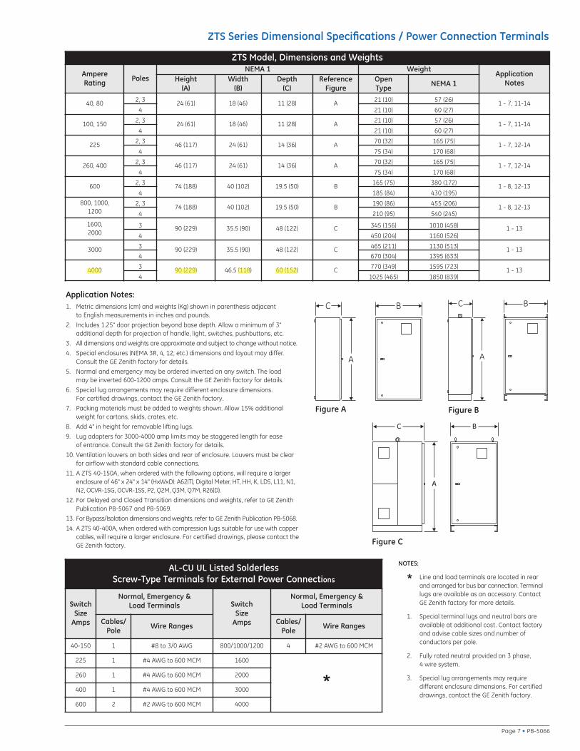
1. Metric dimensions (cm) and weights (Kg) shown in parenthesis adjacent to English measurements in inches and pounds.
2. Includes 1.25" door projection beyond base depth. Allow a minimum of 3" additional depth for projection of handle, light, switches, pushbuttons, etc.
3. All dimensions and weights are approximate and subject to change without notice.
4. Special enclosures (NEMA 3R, 4, 12, etc.) dimensions and layout may differ.Consult the GE Zenith factory for details.
5. Normal and emergency may be ordered inverted on any switch. The load may be inverted 600-1200 amps. Consult the GE Zenith factory for details.
6. Special lug arrangements may require different enclosure dimensions. For certified drawings, contact the GE Zenith factory.
7. Packing materials must be added to weights shown. Allow 15% additionalweight for cartons, skids, crates, etc.
8. Add 4" in height for removable lifting lugs.
9. Lug adapters for 3000-4000 amp limits may be staggered length for ease of entrance. Consult the GE Zenith factory for details.
10. Ventilation louvers on both sides and rear of enclosure. Louvers must be clearfor airflow with standard cable connections.
11. A ZTS 40-150A, when ordered with the following options, will require a largerenclosure of 46" x 24" x 14" (HxWxD): A62(T), Digital Meter, HT, HH, K, LDS, L11, N1,N2, OCVR-1SG, OCVR-1SS, P2, Q2M, Q3M, Q7M, R26(D).
12. For Delayed and Closed Transition dimensions and weights, refer to GE ZenithPublication PB-5067 and PB-5069.
13. For Bypass/Isolation dimensions and weights, refer to GE Zenith Publication PB-5068.
14. A ZTS 40-400A, when ordered with compression lugs suitable for use with coppercables, will require a larger enclosure. For certified drawings, please contact theGE Zenith factory.
Application Notes:
NOTES:
* Line and load terminals are located in rearand arranged for bus bar connection. Terminallugs are available as an accessory. ContactGE Zenith factory for more details.
1. Special terminal lugs and neutral bars areavailable at additional cost. Contact factoryand advise cable sizes and number of conductors per pole.
2. Fully rated neutral provided on 3 phase, 4 wire system.
3. Special lug arrangements may require different enclosure dimensions. For certifieddrawings, contact the GE Zenith factory.
C
A
B
Figure A
C
A
B
Figure B
C
A
B
Figure C
ZTS Series Dimensional Specifications / Power Connection Terminals
ZTS Model, Dimensions and Weights
AmpereRating Poles
NEMA 1 WeightApplication
NotesHeight(A)
Width(B)
Depth(C)
ReferenceFigure
OpenType NEMA 1
40, 80 2, 3 24 (61) 18 (46) 11 (28) A 21 (10) 57 (26) 1 - 7, 11-144 21 (10) 60 (27)
100, 150 2, 3 24 (61) 18 (46) 11 (28) A 21 (10) 57 (26) 1 - 7, 11-144 21 (10) 60 (27)
225 2, 3 46 (117) 24 (61) 14 (36) A 70 (32) 165 (75) 1 - 7, 12-144 75 (34) 170 (68)
260, 400 2, 3 46 (117) 24 (61) 14 (36) A 70 (32) 165 (75) 1 - 7, 12-144 75 (34) 170 (68)
600 2, 3 74 (188) 40 (102) 19.5 (50) B 165 (75) 380 (172) 1 - 8, 12-134 185 (84) 430 (195)
800, 1000, 1200
2, 3 74 (188) 40 (102) 19.5 (50) B 190 (86) 455 (206) 1 - 8, 12-134 210 (95) 540 (245)
1600, 2000
3 90 (229) 35.5 (90) 48 (122) C 345 (156) 1010 (458) 1 - 134 450 (204) 1160 (526)
3000 3 90 (229) 35.5 (90) 48 (122) C 465 (211) 1130 (513) 1 - 134 670 (304) 1395 (633)
4000 3 90 (229) 46.5 (118) 60 (152) C 770 (349) 1595 (723) 1 - 134 1025 (465) 1850 (839)
AL-CU UL Listed SolderlessScrew-Type Terminals for External Power Connections
Switch Size
Amps
Normal, Emergency & Load Terminals Switch
Size Amps
Normal, Emergency & Load Terminals
Cables/Pole Wire Ranges Cables/
Pole Wire Ranges
40-150 1 #8 to 3/0 AWG 800/1000/1200 4 #2 AWG to 600 MCM
225 1 #4 AWG to 600 MCM 1600
*260 1 #4 AWG to 600 MCM 2000
400 1 #4 AWG to 600 MCM 3000
600 2 #2 AWG to 600 MCM 4000
Page 7 • PB-5066
user
Highlight
user
Highlight
user
Highlight
user
Highlight
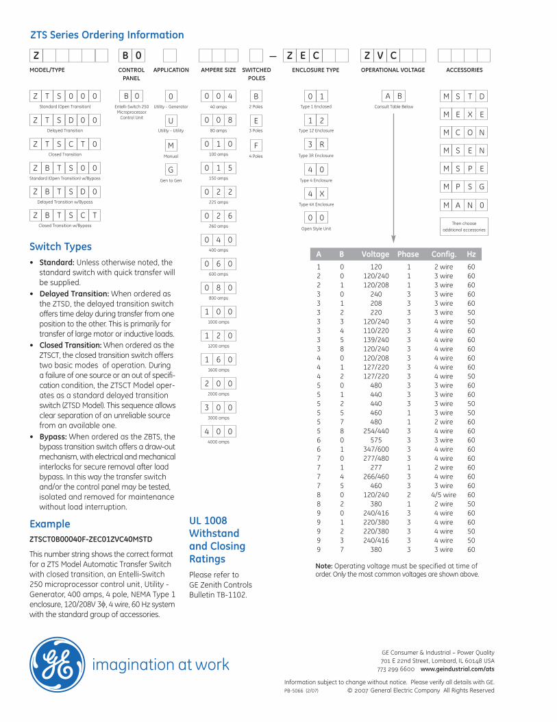
MODEL/TYPE AMPERE SIZE SWITCHEDPOLES
ENCLOSURE TYPE OPERATIONAL VOLTAGE ACCESSORIES
A BConsult Table BelowType 1 Enclosed
Open Style Unit
B2 Poles
F4 Poles
E3 Poles
B 0
Z B 0 Z E C Z V C
T DSM
CONTROLPANEL
Switch Types• Standard: Unless otherwise noted, the
standard switch with quick transfer willbe supplied.
• Delayed Transition: When ordered asthe ZTSD, the delayed transition switchoffers time delay during transfer from oneposition to the other. This is primarily fortransfer of large motor or inductive loads.
• Closed Transition: When ordered as theZTSCT, the closed transition switch offerstwo basic modes of operation. Duringa failure of one source or an out of specifi-cation condition, the ZTSCT Model oper-ates as a standard delayed transitionswitch (ZTSD Model). This sequence allowsclear separation of an unreliable sourcefrom an available one.
• Bypass: When ordered as the ZBTS, thebypass transition switch offers a draw-outmechanism, with electrical and mechanicalinterlocks for secure removal after loadbypass. In this way the transfer switchand/or the control panel may be tested,isolated and removed for maintenancewithout load interruption.
Then chooseadditional accessories
APPLICATION
0Utility - Generator
MManual
GGen to Gen
UUtility - Utility
Type 4 Enclosure
Type 12 Enclosure
Type 4X Enclosure
Type 3R Enclosure
0 1
1 2
3 R
4 0
4 X
0 0
A B Voltage Phase Config. Hz1 0 120 1 2 wire 602 0 120/240 1 3 wire 602 1 120/208 1 3 wire 603 0 240 3 3 wire 603 1 208 3 3 wire 603 2 220 3 3 wire 503 3 120/240 3 4 wire 503 4 110/220 3 4 wire 603 5 139/240 3 4 wire 603 8 120/240 3 4 wire 604 0 120/208 3 4 wire 604 1 127/220 3 4 wire 604 2 127/220 3 4 wire 505 0 480 3 3 wire 605 1 440 3 3 wire 605 2 440 3 3 wire 505 5 460 1 3 wire 505 7 480 1 2 wire 605 8 254/440 3 4 wire 606 0 575 3 3 wire 606 1 347/600 3 4 wire 607 0 277/480 3 4 wire 607 1 277 1 2 wire 60 7 4 266/460 3 4 wire 607 5 460 3 3 wire 608 0 120/240 2 4/5 wire 608 2 380 1 2 wire 509 0 240/416 3 4 wire 60 9 1 220/380 3 4 wire 60 9 2 220/380 3 4 wire 50 9 3 240/416 3 4 wire 509 7 380 3 3 wire 60
Note: Operating voltage must be specified at time oforder. Only the most common voltages are shown above.
X EEM
O NCM
E NSM
P ESM
S GPM
N 0AM
ZTS Series Ordering Information
Entelli-Switch 250Microprocessor
Control Unit
ExampleZTSCT0B00040F-ZEC01ZVC40MSTD
This number string shows the correct formatfor a ZTS Model Automatic Transfer Switchwith closed transition, an Entelli-Switch250 microprocessor control unit, Utility -Generator, 400 amps, 4 pole, NEMA Type 1enclosure, 120/208V 3φ, 4 wire, 60 Hz systemwith the standard group of accessories.
UL 1008Withstandand ClosingRatingsPlease refer to GE Zenith ControlsBulletin TB-1102.
PB-5066 (2/07)
GE Consumer & Industrial – Power Quality701 E 22nd Street, Lombard, IL 60148 USA
773 299 6600 www.geindustrial.com/ats
Information subject to change without notice. Please verify all details with GE. © 2007 General Electric Company All Rights Reserved
Standard (Open Transition)
Z T S 0 0 0
Z T S D 0 0
Z T S C T 0
Z B T S 0 0
Delayed Transition
Closed Transition
Standard (Open Transition) w/Bypass
Z B T S D 0Delayed Transition w/Bypass
Z B T S C TClosed Transition w/Bypass
40 amps
0 0 4
80 amps
0 0 8
100 amps
0 1 0
150 amps
0 1 5
225 amps
0 2 2
260 amps
0 2 6
400 amps
0 4 0
600 amps
0 6 0
800 amps
0 8 0
1000 amps
1 0 0
1200 amps
1 2 0
1600 amps
1 6 0
2000 amps
2 0 0
3000 amps
3 0 0
4000 amps
4 0 0