
Gbh Up at Hi Raju Capstone Project 2006
68
Master’s project Security aspects in Voice over IP systems Submitted by: Gokul Bhupathiraju Date: 11-16-06 Rochester Institute of Technology Department of Telecommunications Engineering and Technology Project advisor: Prof. Mark Indelicato Graduate advisor: Prof. Warren Koontz
-
Upload
walter2458257 -
Category
Documents
-
view
218 -
download
2
description
security voip
Transcript of Gbh Up at Hi Raju Capstone Project 2006

Master’s project
Security aspects in Voice over IP systems
Submitted by:
Gokul Bhupathiraju
Date: 11-16-06
Rochester Institute of Technology
Department of Telecommunications Engineering and Technology
Project advisor: Prof. Mark Indelicato
Graduate advisor: Prof. Warren Koontz

Table of contents
1. Introduction..................................................................................................................... 1
2. Project abstraction........................................................................................................... 2
3. Overview of Packet Telephony....................................................................................... 3
4. Challenges faced by VoIP............................................................................................... 5
5. Solution overview ........................................................................................................... 7
6. H.323............................................................................................................................. 10
6.1. H.225...................................................................................................................... 10
6.1. H.225...................................................................................................................... 10
6.2. H.245...................................................................................................................... 10
6.3. H.323 Components ................................................................................................ 11
6.4. H.323 Gateway to Gateway ................................................................................... 12
6.5. H.323.0-RAS calls through a Gatekeeper.............................................................. 14
6.6. H.323 Security ....................................................................................................... 17
6.6.1 User-authentication mechanisms..................................................................... 18
6.6.2 Generation of security key from a shared password or by DH technique....... 21
6.3.3. Securing H.225/H.245 channels ..................................................................... 25
6.6.4. Media stream confidentiality .......................................................................... 25
6.6.5. Media-stream confidentiality technique using IPSec ..................................... 26
7. SIP................................................................................................................................. 27
7.1. SIP Components..................................................................................................... 27
7.2. SIP Operation......................................................................................................... 28
7.2.1. SIP call without Proxy Server......................................................................... 28
I

7.2.2 SIP call with Proxy Server ............................................................................... 30
7.2.3 SIP registration with the registrar ................................................................... 32
7.3. SIP Security ........................................................................................................... 34
7.3.1. HTTP Basic Authentication ............................................................................ 34
7.3.2. HTTP Digest Authentication........................................................................... 34
7.3.3. S/MIME or Secure MIME (Multipurpose Internet Mail Extension) ............... 34
7.3.4. TLS (Transport Layer Security) ...................................................................... 35
7.3.5. IP Security (IPSec).......................................................................................... 35
7.3.6. Voice enabled IPSec VPNs ............................................................................. 37
7.3.7. Confidentiality of media data.......................................................................... 38
8. MGCP ........................................................................................................................... 42
8.1. MGCP components................................................................................................ 43
8.2. MGCP Security...................................................................................................... 43
8.3. Megaco/H.248........................................................................................................ 44
8.4. H.248 Security ....................................................................................................... 44
9. NAT and Firewalls........................................................................................................ 46
9.1. Static NAT ............................................................................................................. 46
9.2. Dynamic NAT........................................................................................................ 47
9.3. NAPT (Network Address Port Translation) .......................................................... 47
9.4. NAT issues............................................................................................................. 48
9.5. NAT solutions........................................................................................................ 49
9.5.1. STUN (Simple Traversal of UDP through NATs)........................................... 49
9.5.2. TURN (Traversal using Relay NAT) ............................................................... 49
II
9.5.3. Interactive Connectivity Establishment (ICE) ................................................ 50
9.6. Firewalls................................................................................................................. 50
9.6.1. Network layer firewalls................................................................................... 51
9.6.2. Application layer proxies or gateways (ALG) ................................................ 51
10. VoIP, NAT and Firewall issues and solutions ............................................................ 53
10.1. NAT and Firewall issues...................................................................................... 53
10.2. H.323 Firewall issues........................................................................................... 54
10.3. SIP Firewall issues............................................................................................... 55
10.4. Solutions .............................................................................................................. 55
10.4.1. VoIP-aware firewalls .................................................................................... 55
10.4.2. VLANs ........................................................................................................... 55
10.4.3. Session Border Controllers........................................................................... 56
10.4.4. Other Solutions ............................................................................................. 57
11. Conclusion .................................................................................................................. 58
12. References................................................................................................................... 59
III
Figures
Figure 1: VoIP Components ............................................................................................... 4
Figure 2: H.323 Components ........................................................................................... 12
Figure 3: Call setup from Gateway to Gateway ............................................................... 14
Figure 4: Call setup through a Gatekeeper ...................................................................... 16
Figure 5: Shared/secret key mechanism ........................................................................... 19
Figure 6: Keyed hash technique ....................................................................................... 20
Figure 7: Digital signature technique .............................................................................. 21
Figure 8: DH technique .................................................................................................... 24
Figure 9: Call setup without a Proxy Server .................................................................... 30
Figure 10: Call setup with a Proxy Server ....................................................................... 32
Figure 11: SIP registration............................................................................................... 33
Figure 12: VPN architecture in SIP ................................................................................. 38
Figure 13: AES-CTR method ............................................................................................ 40
Figure 14: Authentication mechanism.............................................................................. 41
Figure 15: MGCP call setup procedure ........................................................................... 42
Figure 16: Static NAT ....................................................................................................... 47
Figure 17: Dynamic NAT.................................................................................................. 47
Figure 18: NAPT............................................................................................................... 48
IV
1. Introduction
In the recent past, IP telephony has become more and more prevalent. The VoIP
technology is creating a “boom” in the telecommunication service industry. VoIP simply
refers to transporting voice communications over IP networks.
VoIP uses the existing network and internet infrastructure to route telephone calls
more efficiently than conventional telephony. It has been a choice of interest because of
the following reasons:
1. It offers lower costs for telephone and internet services
2. It provides more features.
3. It affords flexibility and simplified administration.
The growing popularity of VoIP resulted in increasing concerns about security.
Since VoIP uses the same routes used by the internet, it is subjected to same internet
threats. As a result the topic of “security issues” became the primary point of concern in
VoIP.
1
2. Project abstraction
Security has become a major concern with the rapid growth of interest in the
internet. This project deals with the security aspects of VoIP systems. Various supporting
protocols and technologies are considered to provide solutions to the security problems.
This project stresses on the underlying VoIP protocols like Session Initiation Protocol
(SIP), Secure Real-time Transport Procotol (SRTP), H.323 and Media Gateway Control
Protocol (MGCP). The project further discusses the Network Address Translation (NAT)
devices and firewalls that perform NAT. A firewall provides a point of defense between
two networks. This project considers issues regarding the firewalls and the problems
faced in using firewalls for VoIP; it further discusses the solutions about how firewalls
can be used in a more secured way and how they provide security.
2

3. Overview of Packet Telephony
VoIP is one of the emerging technologies in telecommunications. “VoIP also
called “packet telephony” technology translates analog voice signals into a stream of
digitized packets and sends them over data networks” (“VoIP,” 2006). The VoIP network
combines both voice and data communications technologies.
VoIP traffic can be classified into call signaling, call control and media
communications. Call signaling is a process that is used to set up a connection in a
telephone network. Call control decodes addressing information and routes telephone
calls from one end point to the other. The communications used between the devices
might use either one channel or many channels depending on the VoIP protocols. The
channels used for the connection between devices are TCP/UDP.
Voice networks on PSTN are connection-oriented networks where the path from
the source to destination is established before the information transfer. One of the
advantages is that once the connection has been established, the sequence of information
and delay should be constant. One of the disadvantages is the consumption of resources
while “signaling”.
In connectionless networks like data networks, source and destination addresses
are attached to the packets and put in the networks for delivery to the destination. The
packet might take any route upon availability and there is no guarantee that the packet
arrives at the destination. The delay can vary to a long extent. This unreliable protocol is
called UDP which uses IP.
TCP/IP is not adequate for VoIP. The new protocols should be added to support
time sensitive applications like Voice and Video.
3
In VoIP, audio signals are sent over IP networks to another computer. The sound
samples are recorded and compressed so that they require less space.
CODEC (Coder/Decoder) is a circuit that compresses audio signals. This reduces
bandwidth considerably. “After compressing into small samples, these samples are
collected together into larger chunks and placed into data packets for transmission over
IP networks” (Understanding VoIP,” 1998-2006).
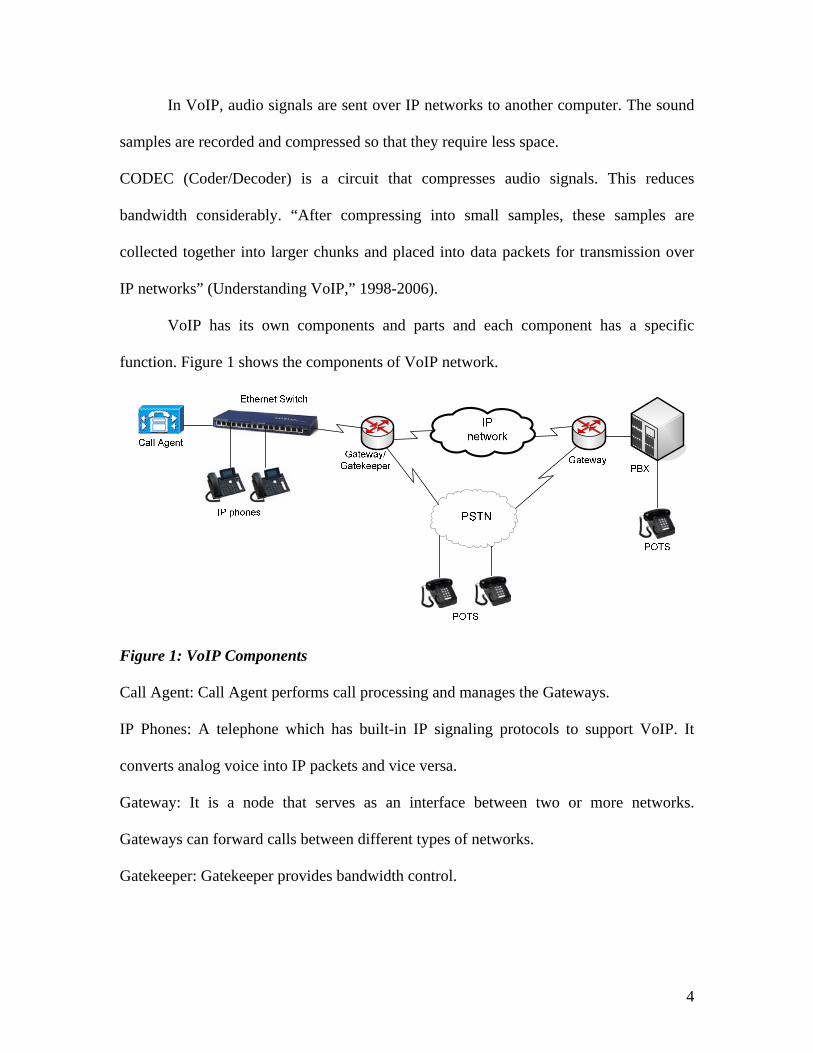
VoIP has its own components and parts and each component has a specific
function. Figure 1 shows the components of VoIP network.
Figure 1: VoIP Components
Call Agent: Call Agent performs call processing and manages the Gateways.
IP Phones: A telephone which has built-in IP signaling protocols to support VoIP. It
converts analog voice into IP packets and vice versa.
Gateway: It is a node that serves as an interface between two or more networks.
Gateways can forward calls between different types of networks.
Gatekeeper: Gatekeeper provides bandwidth control.
4

4. Challenges faced by VoIP
VoIP introduces both opportunities and risks. As VoIP is becoming widespread,
enterprises will be accountable for security risks that affect IP networks. VoIP is
unsecured, and it is subjected to security breaches like Eavesdropping, Packet spoofing
and denial of service attacks. Eavesdropping is one of the most common threats in the
VoIP environment; it is defined as the intercepting and reading of messages and
conversations by unintended recipients. Further, VoIP calls are vulnerable to throughput
problems, packet flooding and unwanted intrusions.
Without a feasible solution, VoIP calls cannot traverse firewalls. When we
connect our private network to the internet, we are physically connecting our network to
so many unknown networks. A firewall provides a point of defense between two
networks. It protects the private network from the public or shared network to which it is
connected but the introduction of firewalls in the VoIP complicates several aspects of
VoIP such as call setup procedures. Firewalls evaluate each packet against the network’s
policy, which is a collection of security rules, conventions and procedures. Therefore
without an acceptable solution firewalls can even block VoIP packets due to their
inherent security rules.
Even the use of IP phones with integrated mechanisms, including authentication
requiring username and password, can be hacked. Using a VoIP solution behind a
firewall may be vulnerable to breaches too, since most enterprises use public IP
addresses.
The use of VLANs (Virtual LANs) allows the enterprise to communicate in a secured
way, but it increases the expenses and the complexity of managing the IP addresses. New
5

voice-aware firewalls are under consideration. This increases the cost of replacing the
existing firewalls with the new ones.
6
5. Solution overview
This project will focus on discussing various solutions to deal with VoIP security.
The solutions involve the inherent security profiles each protocol used, additional
mechanisms and algorithms, IPSec, SRTP, the use of voice proxy firewalls, Application
Level Gateways (ALG) and many more. The voice proxy firewalls in the service
provider’s network support MGCP (Media Gateway Control Protocol) and SIP (Session
Initiation Protocol). Voice proxy firewalls provide powerful firewall capability for
service providers, protecting them from hacker attacks and service disruptions.
There are a number of protocols that are used to provide VoIP communication
services. Virtually every device uses RTP (Real Time Protocol) for transmitting audio
and video packets between communicating computers. A newer improved version of RTP
called Secure RTP provides authentication, encryption and integrity of the audio and
video packets transmitted between communicating devices.
The other protocols that must be employed to find remote devices and to arbitrate
the means by which media will flow between two communicating devices are known as
call signaling protocols. H.323 and SIP are two of the most popular. This paper mainly
focuses on certain protocols namely H.323, SIP and MGCP.
To analyze the above protocols, we define interfaces and functional entities of VoIP
gateways and VoIP gateway controllers.
To offer better security in VoIP, the effective solution for firewalls is to use
VLANs in which phones are connected to one VLAN and devices such as PCs, routers,
and switches are connected to another VLAN. This method allows enterprises to make
and receive VoIP calls through their own firewalls.
7
Firewalls can perform NAT (Network Address Translation). NAT translates
internal private addresses to public IP addresses. NAT enables use of internal private IP
addresses, which share a limited number of public IP address and ports.
H.323
H.323 is a comprehensive protocol which applies intelligence everywhere. An
umbrella standard, H.323 encompasses other standards such as H.225, H.235, etc., with
each one having specific role. It is composed of four components: terminal, gateway,
multipoint control unit and gatekeeper. All the mechanisms that deal with H.323 security
are discussed. Security for H.323 systems is provided in two ways:
1. Security services for signaling messages.
2. Security services for the media streams.
H.235 provides security architecture for H.323 protocol. It supports message
authentication and privacy for H.323-based systems.
SIP
SIP is a less complicated and more flexible protocol. SIP is composed of three
components: endpoints, a proxy server and a redirect server. “SIP offers a security
mechanism for hop-by-hop security and end-to-end security”.
“IPsec (IP security) is a popular network security mechanism which offers transport layer
security” (“Security in SIP based networks,” 1992-2002). Various mechanisms including
implementing VPNs and SRTP are discussed.
8

MGCP
“MGCP is a complementary protocol to SIP and H.323”. It is composed of media
gateway, signaling gateway and media gateway controller. MGCP recommends use of
IPsec which provides security. H.248 protocol and its security mechanisms are also
introduced.
SRTP
This is a secure profile for RTP that provides message authentication and
confidentiality. It can be added to the header of RTP and it has no effect on QOS.
The above described protocols will be discussed and the security profiles in those
protocols will be concentrated. The ways how these existing protocols provide
authentication and security also will be discussed in the project.
9
6. H.323
H.323 is a standard published by the International Telecommunications Union
Telecom Sector (ITU-T). H.323 gateway protocol is an umbrella-like standard that
encompasses many sub-protocols within it such as H.225, H.235, H.245 and others, each
performing a specific action in the process. It is a collection of protocols that perform
functions such as setting up and tearing down VoIP calls, channeling for messages,
commands, and encoding voice conversations etc.
6.1. H.225
This protocol basically performs call setup and termination procedures; it defines
how the protocol frames the voice and video bits into packets to transport over the
channel. It handles the sequence numbering and synchronization to make sure that the
received packets are in the proper order. H.225 protocol has two entities: H.225-Q.931
and H.225-RAS (Registration Admission Status). Q.931 protocol which resides in H.225
deals with signaling between two end points for setting up and releasing calls and
framing data. H.225-RAS specifies messages that describe Registration, Admission,
Status (RAS) functions. It deals with the procedures and signaling between the endpoint
and the Gatekeeper.
6.2. H.245
This protocol performs call control procedures. It specifies signaling, flow control
and channeling for messages. It maintains the synchronization between the transmitter
and the receiver. It also enables the CODEC selection. G.711 and G.729 are widely used
CODECs.
10

6.3. H.323 Components
H.323 is a protocol which applies intelligence everywhere. The H.323 network
contains elements like H.323 Gateway, H.323 Gatekeeper, H.323 Multipoint control unit
(MCU) and H323 terminal.
H.323 Gateway acts like a bridge and serves as a communication point between
H.323 and non-H.323 networks. Any traffic that comes from a PSTN network or
that supports SIP or any other protocol routes through the H.323 Gateway. The
Gateway routes calls from an H.323 terminal to an outside network or from an
outside network to an H.323 network.
The Gatekeeper is an optional but important entity. It provides bandwidth control
and serves as a “traffic cop” for the IP network. The Gateway or a call manager
requests permission from the Gatekeeper before processing a call. The Gatekeeper
grants permission to the gateway or a call manager based on the bandwidth
availability in the IP WAN network. The Gatekeeper could deny a call request if
there is no sufficient bandwidth to support a call. The Gatekeeper performs
address resolution; H.323 alias numbers, E.164 addresses (phone numbers) or
URLs should be resolved to IP addresses in order to route the call through the IP
network. H.225.0 Annex G protocol that resides in a Gateway or a Gatekeeper
divides the network into domains for resolving alias addresses.
Multipoint Control Unit manages the signaling to add or remove participants in a
conference. Multipoint Control Unit contains Multipoint controller and Multipoint
processor for handling call control and media exchange in a conference.
11
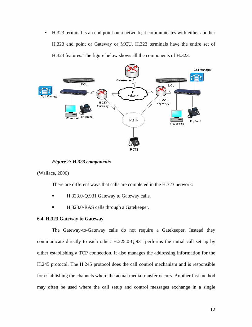
H.323 terminal is an end point on a network; it communicates with either another
H.323 end point or Gateway or MCU. H.323 terminals have the entire set of
H.323 features. The figure below shows all the components of H.323.
Figure 2: H.323 components
(Wallace, 2006)
There are different ways that calls are completed in the H.323 network:
H.323.0-Q.931 Gateway to Gateway calls.
H.323.0-RAS calls through a Gatekeeper.
6.4. H.323 Gateway to Gateway
The Gateway-to-Gateway calls do not require a Gatekeeper. Instead they
communicate directly to each other. H.225.0-Q.931 performs the initial call set up by
either establishing a TCP connection. It also manages the addressing information for the
H.245 protocol. The H.245 protocol does the call control mechanism and is responsible
for establishing the channels where the actual media transfer occurs. Another fast method
may often be used where the call setup and control messages exchange in a single
12

exchange of messages between the Gateways. Figure 3 shows how a call is setup in a
Gateway-to-Gateway model by the exchange of H.323.0-Q.931 messages that are
necessary for call setup and termination.
Endpoint 1 obtains the address of the Endpoint 2 Gateway from the URL. It then
fetches the Endpoint 2 IP address 192.168.0.101 in this case and the TCP port
number 1720 from the Endpoint 2 Gateway. Port 1720 is usually used for call
signaling for TCP.
Endpoint 1 opens a TCP connection with Endpoint 2 for call signaling. It sends a
call setup message to the Endpoint 2 Gateway. The setup message has the
source’s IP address 129.168.0.3 and port numbers 1070 for call signaling
(H.225.0-Q.931) and 1080 for call control (H.245) messages.
The Endpoint 2 Gateway upon receiving the setup message alerts Endpoint 2 and
sends an alert message to Endpoint 1. The Endpoint 1 Gateway stops alerting
Endpoint 1 if the user takes the call.
The connect message contains the Endpoint 2 IP address 192.168.0.101 and the
TCP port 2060 for H.245 messages.
Once the H.245 messages have been exchanged and the connection has been
established, RTP and RTCP streams flow through them.
Once the call is completed, either endpoint sends the release complete (Kumar,
Korpi & Sengodan, 2001).
13

End point 1
H.323Gateway
H.323Gateway
End point 2
H.225.0-Q.931 Call setup
Call alerting
H.245 address port negotiation
H.245 messages exchange
RTP stream
RTCP steam
IP address 129.168.0.3
TCP ports 1070, 1080 TCP ports 1720, 2060
IP address 192.168.0.101
129.168.0.3TCP port 1070
192.168.0.101TCP port 1720
Connect
129.168.0.3TCP port 1080
192.168.0.101TCP port 2060
Release complete
Figure 3: Call setup from Gateway to Gateway
(Wallace, 2006)
6.5. H.323.0-RAS calls through a Gatekeeper
For this topology, the H.225 defines RAS (Registration Admission Status)
protocol for communicating with the Gatekeeper. Gatekeepers provide address translation
and bandwidth management. Endpoints send call signaling messages directly to the peer
endpoints. Gatekeeper has an optional feature of call signal routing in which end points
send call signaling to the Gatekeeper and Gatekeeper sends it to the destination end point.
The figure below shows how a call is setup through a Gatekeeper.
Before calling endpoint 2, Endpoint 1 discovers its Gatekeeper by sending a
Gatekeeper request (GRQ) message. There are two kinds of Gatekeeper
discovery: manual and automatic. In the manual discovery the transport address
14
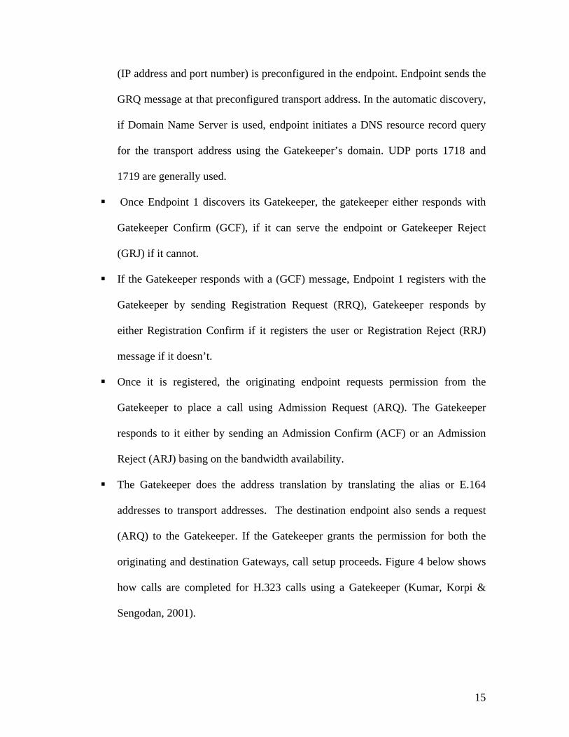
(IP address and port number) is preconfigured in the endpoint. Endpoint sends the
GRQ message at that preconfigured transport address. In the automatic discovery,
if Domain Name Server is used, endpoint initiates a DNS resource record query
for the transport address using the Gatekeeper’s domain. UDP ports 1718 and
1719 are generally used.
Once Endpoint 1 discovers its Gatekeeper, the gatekeeper either responds with
Gatekeeper Confirm (GCF), if it can serve the endpoint or Gatekeeper Reject
(GRJ) if it cannot.
If the Gatekeeper responds with a (GCF) message, Endpoint 1 registers with the
Gatekeeper by sending Registration Request (RRQ), Gatekeeper responds by
either Registration Confirm if it registers the user or Registration Reject (RRJ)
message if it doesn’t.
Once it is registered, the originating endpoint requests permission from the
Gatekeeper to place a call using Admission Request (ARQ). The Gatekeeper
responds to it either by sending an Admission Confirm (ACF) or an Admission
Reject (ARJ) basing on the bandwidth availability.
The Gatekeeper does the address translation by translating the alias or E.164
addresses to transport addresses. The destination endpoint also sends a request
(ARQ) to the Gatekeeper. If the Gatekeeper grants the permission for both the
originating and destination Gateways, call setup proceeds. Figure 4 below shows
how calls are completed for H.323 calls using a Gatekeeper (Kumar, Korpi &
Sengodan, 2001).
15
Requests (H.225 RAS)
Acknowledgments
Figure 4: Call setup through a Gatekeeper
(Wallace, 2006)
16
6.6. H.323 Security
H.323 standard does not mandate any security features, so a security standard
H.235 is defined which offers various security mechanisms at different security levels.
H.235v2 is the updated version of H.235 and includes the following:
Annex D: Relies on symmetric encryption methods like shared secrets and keyed
hashes (Baseline Security Profile)
Annex E: Relies on asymmetric encryption methods like digital signatures
(Signature Security Profile).
Annex F: Relies both on symmetric and asymmetric methods (Hybrid Security
Profile).
H.235v3 provides better security support. H.235v3 Annex G supports the Secure
Real-time Transport Protocol (SRTP). “SRTP provides confidentiality, message
authentication and replay protection for RTP/RTCP traffic” (“SRTP,” 2003-2006). Key
Management (MIKEY) sets up security alliance for multimedia sessions. MIKEY
provides three options for providing user authentication and arbitrating the keys. They are
as follows:
Symmetric key distribution
Asymmetric key distribution
Diffie Hellman key agreement with digital signatures
H.235v3 Annex H deals with the RAS key management process that happens during the
RAS Gatekeeper discovery phase. During the phase a shared secret is established
between the Gatekeeper and the endpoint. Different algorithms were used to encrypt the
key using the shared secret (Ransome & Rittinghouse, 2006).
17
The above-defined core security mechanisms were discussed in detail. Security for H.323
systems can be bifurcated into two categories:
Security services for signaling messages (H.225, RAS and H.245) that are used
for registration of endpoints, admission and status of calls.
Security services for the media streams (RTP, RTCP etc) that provide
confidentiality for transmitted data.
Security services for signaling messages mainly include the following
mechanisms:
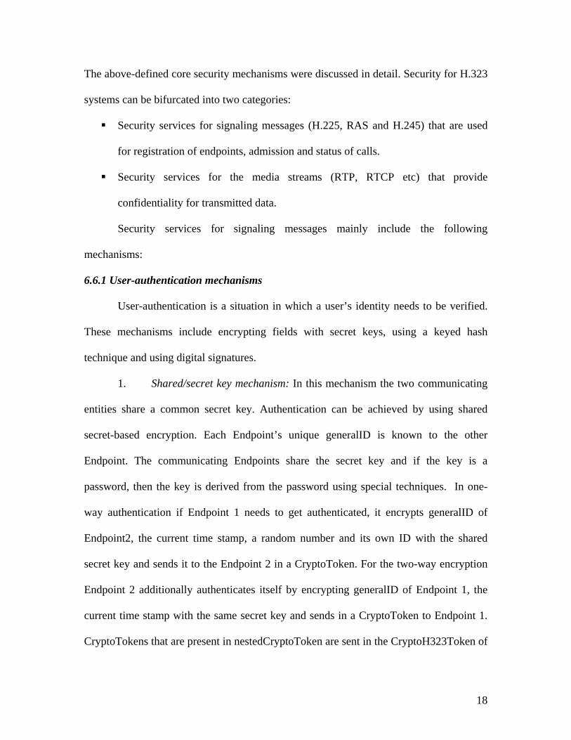
6.6.1 User-authentication mechanisms
User-authentication is a situation in which a user’s identity needs to be verified.
These mechanisms include encrypting fields with secret keys, using a keyed hash
technique and using digital signatures.
1. Shared/secret key mechanism: In this mechanism the two communicating
entities share a common secret key. Authentication can be achieved by using shared
secret-based encryption. Each Endpoint’s unique generalID is known to the other
Endpoint. The communicating Endpoints share the secret key and if the key is a
password, then the key is derived from the password using special techniques. In one-
way authentication if Endpoint 1 needs to get authenticated, it encrypts generalID of
Endpoint2, the current time stamp, a random number and its own ID with the shared
secret key and sends it to the Endpoint 2 in a CryptoToken. For the two-way encryption
Endpoint 2 additionally authenticates itself by encrypting generalID of Endpoint 1, the
current time stamp with the same secret key and sends in a CryptoToken to Endpoint 1.
CryptoTokens that are present in nestedCryptoToken are sent in the CryptoH323Token of
18

H.225 messages. H.245 messages do not contain a field to carry these tokens, so H.245
messages that require user authentication are tunneled within H.225 messages.
CryptoToken has cryptoPwdEncr in which the token field represents the generalID and
time stamp fields encrypted by the secret key. Params indicate any run-time parameters
that are needed by the algorithms. The algorithmOID field denotes the encryption
mechanism.
Figure 5: Shared/secret key mechanism
(Kumar, Korpi & Sengodan, 2001)
Public-key mechanism: This mechanism also generates a CryptoToken but uses
asymmetric encryption. This requires a public key that is known to the entity and grants
authentication and a private key that is known to the entity that requires authentication.
The public key is accessible through a certificate issued by the certification authority. The
digital signature provides the necessary authentication which is produced by encryption
by using the private key.
2. Keyed hash technique: This technique is similar to the shared key
technique except that the CryptoToken contains a hash of the generalID of the
19
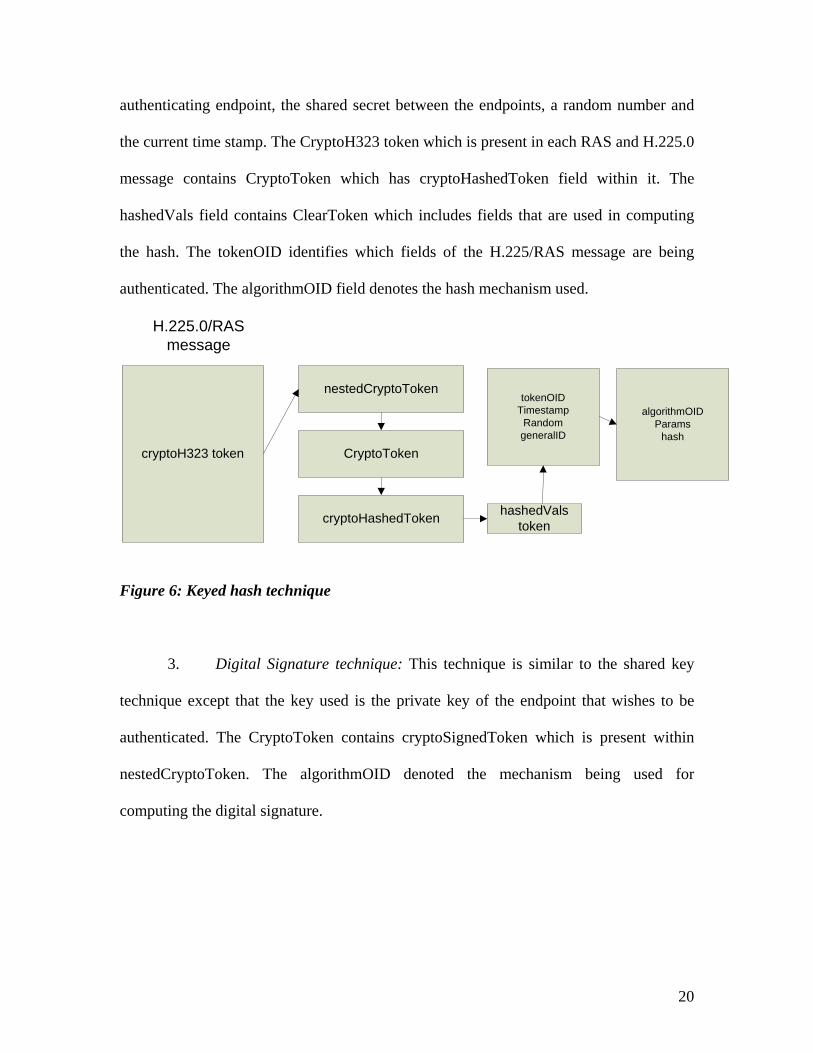
authenticating endpoint, the shared secret between the endpoints, a random number and
the current time stamp. The CryptoH323 token which is present in each RAS and H.225.0
message contains CryptoToken which has cryptoHashedToken field within it. The
hashedVals field contains ClearToken which includes fields that are used in computing
the hash. The tokenOID identifies which fields of the H.225/RAS message are being
authenticated. The algorithmOID field denotes the hash mechanism used.
cryptoH323 token
nestedCryptoToken
CryptoToken
cryptoHashedToken hashedValstoken
algorithmOIDParams
hash
tokenOIDTimestamp
RandomgeneralID
H.225.0/RASmessage
Figure 6: Keyed hash technique
3. Digital Signature technique: This technique is similar to the shared key
technique except that the key used is the private key of the endpoint that wishes to be
authenticated. The CryptoToken contains cryptoSignedToken which is present within
nestedCryptoToken. The algorithmOID denoted the mechanism being used for
computing the digital signature.
20
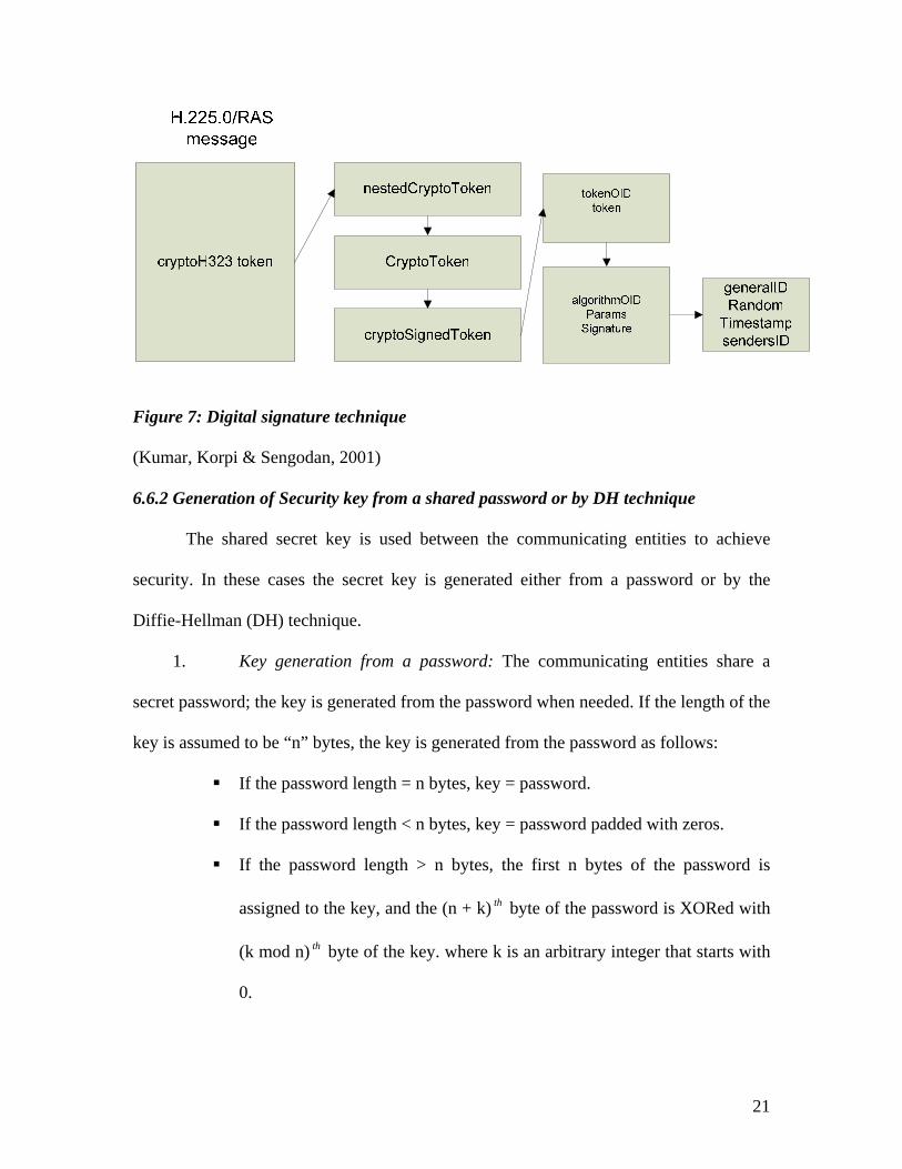
Figure 7: Digital signature technique
(Kumar, Korpi & Sengodan, 2001)
6.6.2 Generation of Security key from a shared password or by DH technique
The shared secret key is used between the communicating entities to achieve
security. In these cases the secret key is generated either from a password or by the
Diffie-Hellman (DH) technique.
1. Key generation from a password: The communicating entities share a
secret password; the key is generated from the password when needed. If the length of the
key is assumed to be “n” bytes, the key is generated from the password as follows:
If the password length = n bytes, key = password.
If the password length < n bytes, key = password padded with zeros.
If the password length > n bytes, the first n bytes of the password is
assigned to the key, and the (n + k) th byte of the password is XORed with
(k mod n) byte of the key. where k is an arbitrary integer that starts with
0.
th
21

Let’s consider an example by taking a password with the key lengths of 16 bits,
96 bits and 128 bits. The password taken is “maRK12”. Unicode standard method is
used; the characters in the password are represented using 16-bit representation in this
standard. ASCII values are considered to represent the characters of the password. The
representation of the password in ASCII is as follows:
Character ASCII equivalent 16-bit representation in binary(Unicode)
M 109 00000000 01101101
A 97 00000000 01100001
R 82 00000000 01010010
K 75 00000000 01001011
1 49 00000000 00110001
2 50 00000000 00110010
In the first case where the key length is 16 bits, the password size is more than the
key length size. Here n = 2 bytes and the password length is 12 bytes which is more than
the key length. So the initial 2 bytes of the password are assigned to the key, then (2+k)
byte of the password is XORed with (k mod 2) th byte of the assigned key, and k = (0, 1,
2…9) until it takes all the bytes of the password.
th
So the key is calculated as follows:
00000000 01101101
XOR 00000000 01100001
XOR 00000000 01010010
22

XOR 00000000 01001011
XOR 00000000 00110001
XOR 00000000 00110010
= 00000000 00010110, which is the key.
In the second case, where the key length is 96 bits, the length of the password is
equal to the key length, so the key is the same as the password.
00000000 01101101 00000000 01100001 00000000 01010010 00000000 01001011
00000000 00110001 00000000 00110010.
In the third case where the key length is 128 bits, it exceeds the length of the
password. Therefore the key is the password padded with the appropriate number of zeros
to make the length 128 bits. It is shown as follows:
00000000 01101101 00000000 01100001 00000000 01010010 00000000 01001011
00000000 00110001 00000000 00110010 00000000 00000000 00000000 00000000.
2. Key generation by Diffie-Hellman (DH) technique: In this technique the
communicating endpoints use the DH technique to generate a secret key. The dhkey that
has parameters is present in the ClearToken in addition to random number, timestamp,
the sender’s ID and generalID. CryptoSignedToken is used within CryptoToken for using
the digital signature to assure the authentication of the endpoints. The token field of the
cryptoSignedToken contains the ClearToken which has all the parameters. AlgorithmOID
denotes the signing algorithm used and the params denotes run-time parameters required
by the algorithm used.
23
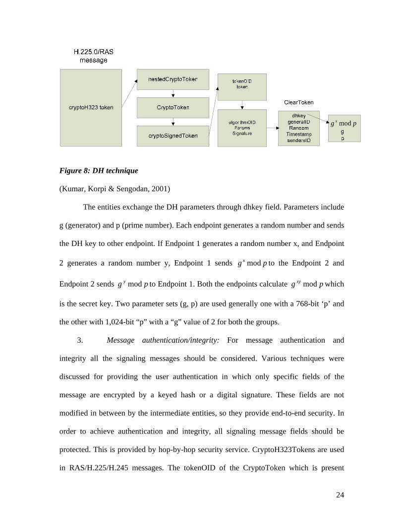
pg x mod
Figure 8: DH technique
(Kumar, Korpi & Sengodan, 2001)
The entities exchange the DH parameters through dhkey field. Parameters include
g (generator) and p (prime number). Each endpoint generates a random number and sends
the DH key to other endpoint. If Endpoint 1 generates a random number x, and Endpoint
2 generates a random number y, Endpoint 1 sends to the Endpoint 2 and
Endpoint 2 sends to Endpoint 1. Both the endpoints calculate which
is the secret key. Two parameter sets (g, p) are used generally one with a 768-bit ‘p’ and
the other with 1,024-bit “p” with a “g” value of 2 for both the groups.
pg x mod
pg y mod pg xy mod
3. Message authentication/integrity: For message authentication and
integrity all the signaling messages should be considered. Various techniques were
discussed for providing the user authentication in which only specific fields of the
message are encrypted by a keyed hash or a digital signature. These fields are not
modified in between by the intermediate entities, so they provide end-to-end security. In
order to achieve authentication and integrity, all signaling message fields should be
protected. This is provided by hop-by-hop security service. CryptoH323Tokens are used
in RAS/H.225/H.245 messages. The tokenOID of the CryptoToken which is present
24
within cryptoH323Token is set so that all fields of the message have the access code or
digital signature.
6.3.3. Securing H.225/H.245 channels
Authentication techniques provide authentication on a per-message basis.
Alternatively the H.224/245 channel can be secured and the signaling messages can be
sent through the channel. IPSec and TLS (Transport Layer Security) are commonly used
mechanism for securing the H.225 channel. Once the channel is secured by IPSec, H.225
messages can be exchanged between the endpoints. The H.245 channel can also be
secured by using the H.225 message exchanges. There is an optional field within H.225
setup that has the different methods of securing the H.245 channel. Upon mutual
agreement of both the communicating endpoints H.225 can secure the H.245 channel.
There is also an option of securing the H.245 channel by combining it with a secure
H.235 logical control channel. The logical channel is secured by mechanisms like IPSec
or TLS.
Security services for the media streams include the following mechanisms:
6.6.4. Media stream confidentiality
Confidentiality is an important security aspect that should be considered. This
service involves two theories:
1. The transmitting endpoint knows the security capabilities of the receiver
by exchanging messages. It then opens a logical channel with the supported security
abilities of the receiver and indicates to receiver that the media stream is encrypted once
they have come to terms on the security mechanism.
25

2. The encryption key is generated by an encryption algorithm used and
distributed to all of the communicating parties. A special field within the H.245 logical
channel messages is used to send the key to the endpoint. The special field contains the
key field which contains the key and the Flag field containing the RTP payload number
that matches the key. The receiver knows that the key to be used for decrypting received
RTP packets by that key and an RTP payload number. It ensures that the distribution of
the key is performed using a secure manner.
6.6.5. Media-stream confidentiality technique using IPSec
IPSec introduces a header called the Encapsulating Security Payload (ESP) for
encryption. ESP encapsulates the user data. Endpoints might also involve the use of
Internet Key Exchange (IKE) which is a shared security policy that requires the use of
pre-shared keys. Endpoints indicate their capability of using these security techniques in
the H.245 capability exchange session. The H235 security capability field has an
identifier that denotes the IPSec capability. Hence when a logical channel is opened,
IPSec based security is indicated.
26

7. SIP
SIP (Session Initiation Protocol) is an application layer-signaling protocol
developed by the Internet Engineering Task Force (IETF) to set up, modify and terminate
multimedia sessions across packet networks. SIP is text based and designed to be
extensible. It can be extended to accommodate features like instant messaging, video and
services like call control services, interoperability and more. SIP can be carried by TCP,
UDP or various other IPs. SIP is used to identify, locate and join entities who wish to
communicate using peer-to-peer media type.
7.1. SIP Components
The SIP network is composed of the following types of entities each having
specific functions to perform:
User agent: User agent is a SIP endpoint entity. User agents are an interface
between the user and the SIP environment. They initiate and terminate sessions by
exchanging responses and requests. A user agent can be a client or a server.
User Agent Client (UAC): an application that initiates and sends SIP requests.
User Agent Server (UAS): an application that receives SIP requests.
SIP devices can communicate directly if the endpoints know each other’s URI (Uniform
Resource Identifier) or IP address, but SIP servers are used for providing a means for
routing, registration and authentication services.
Registrar Server: The Registrar Server authenticates and registers users when
they come online. It updates the location database with the contact details and stores
them.
27
Proxy Server: “A Proxy Server is an entity that acts both as a server and a client”.
A proxy takes the requests and interprets them; it can modify a SIP request, if necessary,
before forwarding it. A proxy is involved only in setup and termination sessions.
Redirect Server: A Redirect Server obtains the actual address from the location
server, takes a SIP request and maps the SIP address of the destined user to the address of
the device closest to the user and returns it to the client.
Location Server: A Location Server is a data base that keeps track of users and
their locations. The location server gets its information from the Registrar and provides
address resolution for Proxy and Redirect Servers.
7.2. SIP operation
7.2.1. SIP call without Proxy Server
The setup process shown below describes the basic SIP setup between two user
agents. It is assumed that each user agent knows the other’s URI or IP address (sip: 585-
[email protected]; user=phone is an example of an URI)
User Agent Client (UAC) originates the call. The destination server (UAS)
responds if it wishes to join the session.
UAC begins the message exchange by sending an invite message to the called
user, known here as User Agent Server (UAS). The invite message contains
Session Description Protocol (SDP) that defines details of the type of session that
is requested.
The fields listed in the invite message are called headers. There are different
headers like via header which has the sending SIP device’s address, SIP version
and the default port number which is 5060. The next headers To and From
28
indicate the originator and destination of the SIP request. “The other headers like
Content-Type and Content-Length indicate that the message body is SDP which
has the connection IP address, media format, port number, media transport
protocol, media encoding and sampling rate” (Johnston, 2001).
Invite message is a SIP request message; the next message is the ringing message
from the called party in response to the invite message. The Ringing message
signifies that the called party received the invite message and is ringing.
When the destination party answers the call, an ok message is sent to the calling
party. This also indicates that the caller’s type of media session is acceptable by
the called party. The ok message body contains the called party’s media
information and a SDP message body that is added to the response.
The called party sends an acknowledgment request to confirm the media request.
The media session is established and the media session takes place using RTP
(Road Transport Protocol) (Johnston, 2001).
The figure below shows how communication takes place without the use of
Proxy or Redirect Servers.
29
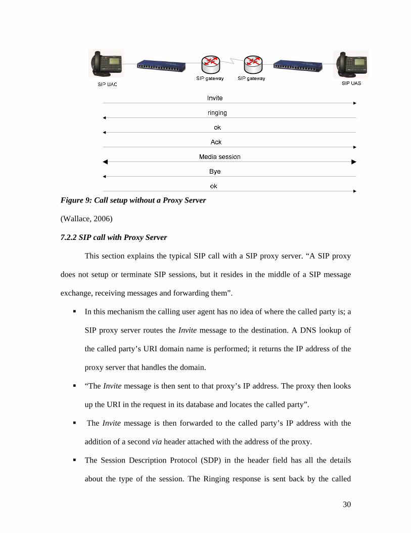
Figure 9: Call setup without a Proxy Server
(Wallace, 2006)
7.2.2 SIP call with Proxy Server
This section explains the typical SIP call with a SIP proxy server. “A SIP proxy
does not setup or terminate SIP sessions, but it resides in the middle of a SIP message
exchange, receiving messages and forwarding them”.
In this mechanism the calling user agent has no idea of where the called party is; a
SIP proxy server routes the Invite message to the destination. A DNS lookup of
the called party’s URI domain name is performed; it returns the IP address of the
proxy server that handles the domain.
“The Invite message is then sent to that proxy’s IP address. The proxy then looks
up the URI in the request in its database and locates the called party”.
The Invite message is then forwarded to the called party’s IP address with the
addition of a second via header attached with the address of the proxy.
The Session Description Protocol (SDP) in the header field has all the details
about the type of the session. The Ringing response is sent back by the called
30

party to the proxy. The response contains the via headers and the To and From,
call-ID headers from the Invite request.
The Proxy receives the response, checks that the first via header has its own
address, removes that via header and forwards the response to the address in the
next via header.
“If the call is accepted by the called party, an ok message is sent to the proxy. The
proxy forwards the ok message to the called party after removing the first via
header”.
The presence of contact header with the URI address of the calling party in the ok
message allows the called party to send the acknowledgement directly to the
destination without going through the proxy. This request and all further requests
continue to use the contact tag in the header.
The media is always end to end and not through the proxy server.
The Bye message from the called party ends the Media Session. The calling party
confirms it by sending an ok response (Johnston, 2001).
The figure below shows how communication takes place between user agents
with a proxy server in between them.
31

Figure 10: Call setup with a Proxy Server
7.2.3 SIP registration with the registrar
Users need to register with the registration server, so that a proxy server could
access the database to fetch the IP address with which a user wants to communicate with.
In the figure below, an UA sends a SIP register request to the SIP registration server. The
registration server receives the message and as a result knows its IP address. The register
message contains the URI address of the UA. The registrar server stores the SIP URI and
the IP address of the UA in the database that can be used. When a proxy server with an
access to the database receives an Invite message, the request will be proxied to the stored
IP address.
32

Figure 11: SIP registration
(Johnston, 2001)
33
7.3. SIP Security
7.3.1. HTTP Basic Authentication
The SIP proxy server supports HTTP basic authentication. It requires the
transmission of username and password embedded in the SIP request. This information
could be used by a SIP proxy server or destination user agent to authenticate a SIP client
or a previous SIP hop in a proxy chain. SIP version 2 disapproved this basic
authentication method because it poses a serious security risk as the clear text password
could be easily sniffed.
7.3.2. HTTP Digest Authentication
The SIP proxy server supports HTTP digest authentication. This mechanism is an
improvisation on the glitches of the HTTP basic authentication. “The password is never
sent across the network in clear text; it is transmitted as an MD5 or SHA-1 digest of the
user’s password. By using this digest authentication, sniffing traffic on the network
cannot identify the password and the identity can be established without transmitting the
passwords in the clear text” (Ransome & Rittinghouse, 2005).
This procedure is vulnerable to attacks if short or weak passwords are used and it
lacks encryption technique so no confidentiality or integrity can be guaranteed.
7.3.3. S/MIME or Secure MIME (Multipurpose Internet Mail Extension)
SIP messages carry MIME bodies. The MIME standard includes mechanisms to
secure its contents to ensure confidentiality and integrity by using multipart/signed and
application/pkcs7-mime MIME types. In the application/pkcs7-mime type the data is
enveloped. The MIME entity to be enveloped is encrypted and packed into an object and
then inserted into an application/pkcs7-mime MIME entity. “SIP may use S/MIME to
34

enable mechanisms like public key distribution, authentication and confidentiality of SIP
data”. Encryption of MIME bodies requires having the destination’s certificate and
private keys; the certificates may be self generated or issued by a trusted third party
(Ransome & Rittinghouse, 2005).
7.3.4. TLS (Transport Layer Security)
“TLS protects SIP signaling messages against loss of integrity and confidentiality
and against replay”. It can provide key management with mutual authentication and
secure key distribution. TLS must be used on the whole path on every component in the
SIP system. It must be used on a hop-by-hop basis on each segment of the path. TLS
requires use of TCP as a transport protocol and requires a public key infrastructure. It
cannot be applied to UDP based SIP signaling. TLS is used for proxies, registrar and
redirect servers and user agents for providing protection for SIP signaling.
7.3.5. IP Security (IPSec)
IPSec is a standard that can provide security functions for SIP signaling at the IP
layer. “IPSec provides authentication, integrity and confidentiality for the data and
supports end-to-end and hop-by-hop methods” (Cisco Systems, 1992-2002). It works for
all TCP, UDP and SCTP based SIP signaling. There are three protocols that are used in
IPSec implementation.
Encapsulating security payload (ESP) protocol: This protocol provides
security services such as confidentiality, authentication, connectionless integrity and anti-
replay service. “Security services can be provided between the communicating user
agents, between a pair of communicating gateways or between a gateway and a user
agent”. ESP may be used alone or in combination with another protocol called
35

Authentication Header (AH). ESP completely encapsulates the user data. “ESP header is
embedded after the IP header and before the upper layer protocol header in the transport
mode or before an encapsulated IP header in the tunnel mode”. ESP protects the fields
that are after the ESP header. The transport mode provides protection for upper layer
protocols, but not for the IP header. In the tunnel mode, ESP protects the entire packet.
Confidentiality of traffic can be best achieved when implemented at a security gateway
with the tunnel mode selected (Kent & Atkinson, 1998).
Authentication Header (AH) protocol: AH protocol can be used alone or
in combination with ESP. AH protocol provides authentication and connectionless
integrity for IP datagrams. The primary difference between the authentications provided
by ESP and AH is the extent of coverage. Like ESP, AH can be used in two modes:
transport mode and tunnel mode. The functions of both modes in AH protocol are almost
similar to that in ESP protocol.
Internet key exchange protocol: internet key exchange protocol is a hybrid
protocol that is used to establish a shared secret authentication keys for services that
require keys. The peers should identify themselves to the hosts before any IPSec traffic is
passed; this is done by entering pre-shared keys by the communicating hosts or by a
certification authority (CA). This protocol uses part of Oakley and SKEME inside the
ISAKMP frameworks. These frameworks describe key exchanges and key exchange
techniques. This protocol can be used for negotiating VPNs and providing access for a
remote user to a secure host (Harkins & Carrel, 1998).
36

7.3.6. Voice enabled IPSec VPNs
“IPSec can be used to encrypt the traffic between two hosts known as transport
mode or to build virtual tunnels between two networks which could be used to provide
secure communication across the network which is known as tunnel mode or VPN”. The
traffic flowing across the shared network can be secured as if it were flowing on a private
network. A VPN tunnel is created as a logical point-to-point secured connection over a
VoIP network. IPSec is widely used to secure the VPN link. IPSec provides a mechanism
for the hosts to agree on an encryption key and a virtual network link needs to be created
before implementing IPSec. The communicating Gateways need to have public IP
addresses and private IP addresses. The Gateway needs to know how to reach the IP
address of other Gateway. The packets routed from one Gateway to another Gateway
should appear as if they are from a public IP address and they have to be sent to a public
IP address although they route between private IP addresses. Each packet is wrapped up
within another packet so that they appear to be are routing between public IP addresses.
This process is called encapsulation. Once the packet reaches the destination public IP
address, it needs to be un-encapsulated and delivered to the private IP address.
The following procedure provides an overview of implementing a VPN using
IPSec:
Generic routing encapsulation (GRE) tunnel endpoints are created.
The hosts need to agree on the encryption mechanism to use.
Security and authentication policies are established. The mechanism for
specifying which traffic needs to be encrypted is defined. Crypto maps are
defined.
37

Crypto maps are associated with GRE tunnels. The encrypted voice traffic is
routed through one of the tunnels to the destination
The voice traffic on gateways is identified and classified.
The voice traffic across the tunnel is assigned a higher priority using appropriate
queuing methods (Cisco Systems, 1992-2002).
The following figure shows a VPN using IPSec tunnel:
Figure 12: VPN architecture in SIP
(Cisco Systems, 1992-2002)
7.3.7. Confidentiality of media data
SIP doesn’t consider encrypting the media data. Using the RTP encryption
provides confidentiality for media data. An option for providing media security is the use
of SRTP (Secure Real-time Transport Protocol). Session Description Protocol (SDP) is
used to convey the session keys for media streams. SDP does not use any method to send
an encrypted media stream key, so signaling message should be encrypted by using end
to end encryption.
SRTP is an extension to RTP; “it provides confidentiality, message
authentication, integrity and replay protection to RTP and RTCP traffic”. Both RTP and
RTCP can be cryptographically secured by the SRTP and Secure Real-time Transport
Control Protocol (SRTCP) respectively. SRTP provides features on key management and
on increasing security. It generates a master key that can provide key material for
38
confidentiality and integrity protection. This is achieved by SDP with a key derivative
function that provides session keys which are securely derived from the master key.
SRTP intercepts RTP packets and forwards equivalent SRTP packets from the
sending side. On the receiving side SRTP packets are intercepted and equivalent RTP
packets are passed. SRTCP provides the same security services to RTCP as SRTP
provides to RTP. SRTP only encrypts the RTP payload. Each SRTP packet contains 16
bit sequence number and a 32-bit roll over counter which is a part of cryptographic
context; they are used for the SRTP session to prevent replay attacks. The MKI (Master
Key Identifier), which is an optional field, identifies the master key from which the
session keys are acquired. It contains an authentication tag that computes checksum over
both the header and the payload of the RTP packet. An authentication tag is
recommended, because it provides authentication of the RTP header and the payload and
protects the packet from unauthorized modification.
A secure RTCP packet has an SRTCP index which is used as a sequence counter
to prevent replay attacks. RTCP packets are controlled in the same way as the RTP
packets except here the use of the authentication tag is mandatory.
Default encryption algorithms NULL cipher and the Advanced Encryption
Standard in counter mode (AES-CTR) are defined.
39
RTP/RTCP payload
Encry key AES-CTR
XOR
Encrypted payload
Vector
128 bits
128 bits
Figure 13: AES-CTR method
(Steffen, Kaufmann & Stricker, 2004).
“AES acts as a key stream generator that generates a pseudo-random key stream
that is bit-wise XORed with the RTP/RTCP payload. AES-CTR is loaded with a distinct
initialization vector at the start of each RTP/RTCP payload packet to make it work like a
pseudo-random generator. Encrypting the vector results in an output of 128 pseudo-
random bits; next the vector is incremented by one and encrypted again to generate the
next 128 pseudo-random bits. The bits are generated as many times as required to encrypt
the whole RTP/RTCP packets” (Steffen, Kaufmann & Stricker, 2004).
Authentication mechanism: “The authentication mechanism used is HMAC-SHA-
1 algorithm based on the 160-bit hash function. Authentication is achieved by hashing a
160-bit secret authorization key into the checksum which is then cropped to 80 bits. In
cases where bandwidth is limited, the authorization tag may be cropped to 32 bits.
40

Figure 14: Authentication mechanism
(Steffen, Kaufmann & Stricker, 2004)
The encryption and authentication mechanisms require secret symmetric key
session keys that must be known to entities participating in a SIP session. A SRTP
standard offers a solution by deriving necessary session keys from the master key.
Session Description Protocol (SDP) can be used to transfer the master key” (Steffen,
Kaufmann & Stricker, 2004).
41
8. MGCP
“MGCP (Media Gateway Control Protocol) is a complementary protocol to H.323
and SIP”. “MGCP is a protocol that is used for controlling gateways from external call
control units called Media Gateway Controllers (MGCs) or call agents”. MGCP gateways
do not have call forwarding intelligence. Call control intelligence is outside the gateways
and handled by external call control agents. The call agents synchronize with each other
to send commands to the gateways under their control; they manage the calls and
conferences and support the services provided. “MGCP is a master/slave protocol with a
tight coupling between the Gateway and call agent/server” (Ransome & Rittinghouse,
2005). The figure below shows the basic MGCP call setup procedure:
Figure 15: MGCP call setup procedure
42
8.1. MGCP components
The components of an MGCP network include:
Endpoints: An endpoint is an interface between the VoIP network and the
traditional telephony network. Endpoints are sources and sinks of data and could
be physical or virtual.
Gateways: MGCP categorizes different types of gateways, which convert audio
between different types of networks. The Gateways follow the commands issued
by their call agents that control them.
Call agents: MGCP call agents have the intelligence of MGCP networks; they
control the gateways and their endpoints. Call agents handle signaling and call
processing functions; they take the responsibility for setting up calls and
establishing the rules for communication and then back out once the calls are
established.
After the call has been established, the call agent backs out and the RTP (Real
time Transport Protocol) data is exchanged directly between the communicating
gateways. The use of MGCP by the call agent, provides the description of connection
parameters like IP addresses, UDP ports and RTP profiles to the gateways.
8.2. MGCP Security
MGCP does not have any inherent security mechanisms. Use of IPSec either ESP
or AH, is recommended to protect the MGCP messages. Call agents can make the MGCP
gateways use the session keys to encrypt the audio messages. The session keys are
transmitted to the gateway by the call agent through Session Description Protocol (SDP).
43
8.3. Megaco/H.248
Megaco/H.248 is a result of a joint effort of the standards IETF and ITU-T. This
protocol is primarily used to separate the call control from the media conversion in a
gateway. H.248 has a master/slave configuration in which a single controller controls a
number of gateways through this protocol. H.248 is also known as Megaco protocol.
“Megaco/H.248 introduces many enhancements compared to MGCP which
include:
Support of multimedia and multipoint conferencing services.
TCP and UDP transport options.
Use of either text or binary encoding.
Formalized extension process for enhanced functionality.
Expanded definition of packages” (Ransome & Rittinghouse, 2005).
H.248 has two entities: Contexts and Terminations. Terminations are media
streams that enter and leave the gateway. Contexts are controlled by the gateway media
controller that can have terminations added and removed. If establishing a multipoint
conference is considered for an instance, MGCP has to establish many connections with
the conference server whereas H.248 can simply add several terminations to a context.
8.4. H.248 Security
The security profile of H.248 is almost similar to that of MGCP. H.248 protocol
recommends security mechanisms like IPSec if the underlying operating system supports
the use of IPSec. The protocol requires implementation of an Authorization Header (AH)
that provides a set of algorithms for integrity checking using manual keys. The H.248
44
protocol may also use Encapsulating Security Payload (ESP) to provide encryption and
integrity checking; further more, it can use Internet Key Exchange protocol (IKE),
supporting authentication with signatures and public key encryption.
45
9. NAT and Firewalls
Network Address Translation (NAT) is a powerful tool for providing network
security. “NAT hides internal network addresses and allows several endpoints within a
LAN to use the same external IP address”. In addition, NAT changes the outgoing IP
header from private IP addresses to the router’s global IP addresses and provides a layer
of security by hiding the internal IP addresses from the internet. A NAT is usually a
router or a firewall that separates two domains on the internet. NAT was initially
introduced as a temporary solution to the problems of IP space shortage in IPV4.
A NAT device seems like a source/destination for all traffic originating from
behind the NAT device because hosts behind NAT devices do not have an end-to-end
connectivity. NAT devices record and change the source and destination IP addresses and
checksum fields within IP headers once they reach the devices.
NAT has three modes of operation:
9.1. Static NAT
In static NAT each private internal IP address is mapped to a public external IP
address. The number of internal IP addresses is equal to the number of external IP
addresses. Static NAT manages the translations between IP addresses by maintaining a
look-up table. The figure below shows the static NAT process:
46
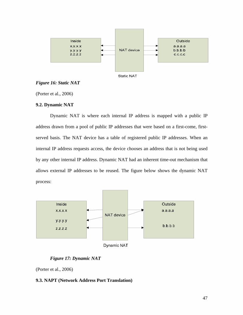
Figure 16: Static NAT
(Porter et al., 2006)
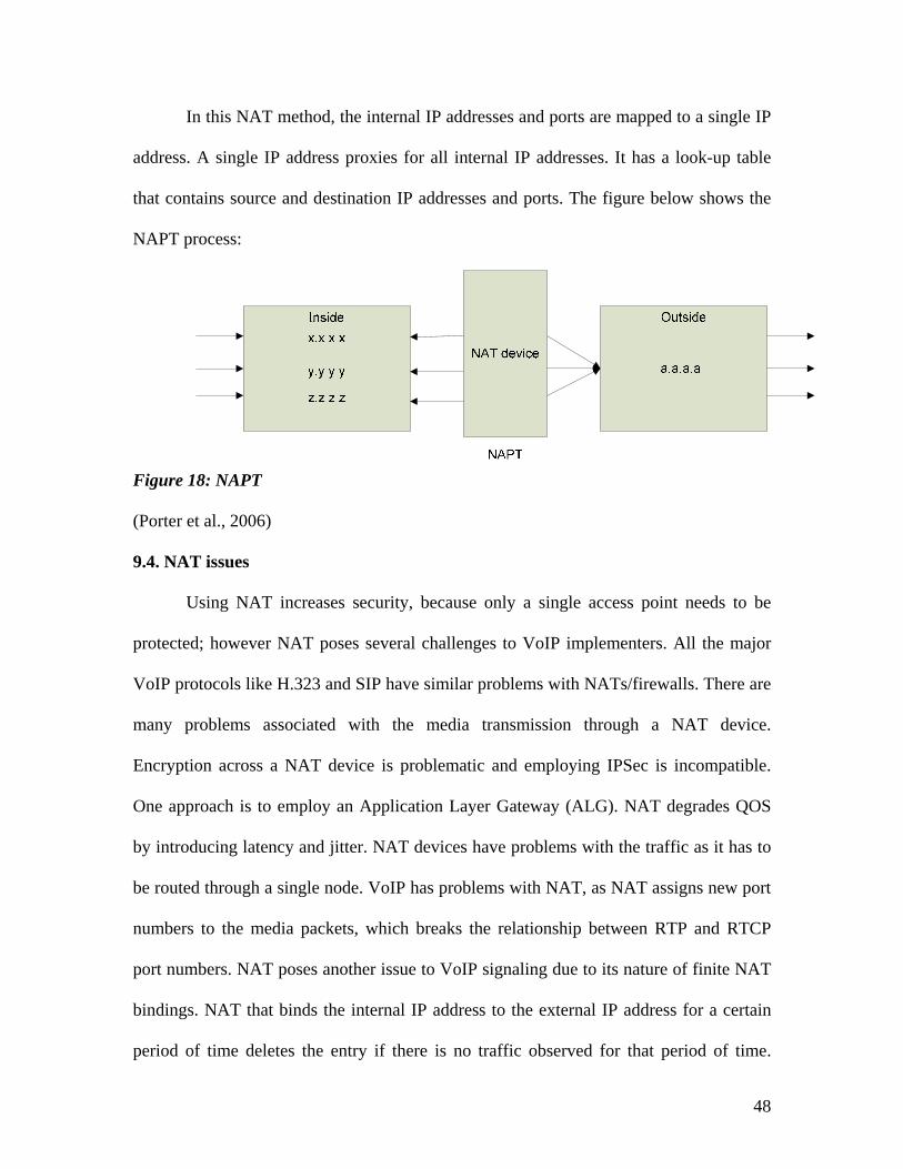
9.2. Dynamic NAT
Dynamic NAT is where each internal IP address is mapped with a public IP
address drawn from a pool of public IP addresses that were based on a first-come, first-
served basis. The NAT device has a table of registered public IP addresses. When an
internal IP address requests access, the device chooses an address that is not being used
by any other internal IP address. Dynamic NAT had an inherent time-out mechanism that
allows external IP addresses to be reused. The figure below shows the dynamic NAT
process:
Figure 17: Dynamic NAT
(Porter et al., 2006)
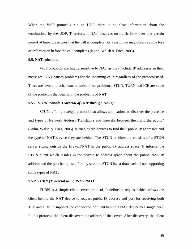
9.3. NAPT (Network Address Port Translation)
47
In this NAT method, the internal IP addresses and ports are mapped to a single IP
address. A single IP address proxies for all internal IP addresses. It has a look-up table
that contains source and destination IP addresses and ports. The figure below shows the
NAPT process:
Figure 18: NAPT
(Porter et al., 2006)
9.4. NAT issues
Using NAT increases security, because only a single access point needs to be
protected; however NAT poses several challenges to VoIP implementers. All the major
VoIP protocols like H.323 and SIP have similar problems with NATs/firewalls. There are
many problems associated with the media transmission through a NAT device.
Encryption across a NAT device is problematic and employing IPSec is incompatible.
One approach is to employ an Application Layer Gateway (ALG). NAT degrades QOS
by introducing latency and jitter. NAT devices have problems with the traffic as it has to
be routed through a single node. VoIP has problems with NAT, as NAT assigns new port
numbers to the media packets, which breaks the relationship between RTP and RTCP
port numbers. NAT poses another issue to VoIP signaling due to its nature of finite NAT
bindings. NAT that binds the internal IP address to the external IP address for a certain
period of time deletes the entry if there is no traffic observed for that period of time.
48
When the VoIP protocols run on UDP, there is no clear information about the
termination, by the UDP. Therefore, if NAT observes no traffic flow over that certain
period of time, it assumes that the call is complete. As a result we may observe some loss
of information before the call completes (Kuhn, Walsh & Fries, 2005).
9.5. NAT solutions
VoIP protocols are highly sensitive to NAT as they include IP addresses in their
messages. NAT causes problems for the incoming calls regardless of the protocol used.
There are several mechanisms to solve these problems. STUN, TURN and ICE are some
of the protocols that deal with the problems of NAT.
9.5.1. STUN (Simple Traversal of UDP through NATs)
STUN is “a lightweight protocol that allows applications to discover the presence
and types of Network Address Translators and firewalls between them and the public”
(Kuhn, Walsh & Fries, 2005). It enables the devices to find their public IP addresses and
the type of NAT service they are behind. The STUN architecture consists of a STUN
server sitting outside the firewall/NAT in the public IP address space. It informs the
STUN client which resides in the private IP address space about the public NAT IP
address and the port being used for any session. STUN has a drawback of not supporting
some types of NAT.
9.5.2. TURN (Traversal using Relay NAT)
TURN is a simple client-server protocol. It defines a request which allows the
client behind the NAT device to request public IP address and port for receiving both
TCP and UDP. It supports the connection of client behind a NAT device to a single peer.
In this protocol, the client discovers the address of the server. After discovery, the client
49

sends a request and negotiates the authentication mechanism with the server. The TURN
server remembers the address from which the request came and returns the public IP
address in its response. Unlike STUN, it provides information about the ports and IP
addresses to the clients that connect to it. The TURN server acts as a relay by receiving
the data on the address it provided to the clients and forwards it.
9.5.3. Interactive Connectivity Establishment (ICE)
This is a protocol which describes NAT traversal for SIP. ICE is not a new
protocol; it uses existing protocols like STUN and TURN. Any protocol that provides the
client with an IP address and port to receive can be used. ICE works through mutual
cooperation of the communicating endpoints in a SIP dialogue.
9.6. Firewalls
Firewalls are a standard of security in IP networks and provide a point of defense
between two networks by implementing an access control policy. Firewalls block traffic
that is considered to be invasive or intrusive. Firewalls block traffic from outside to the
inside but allow users inside to communicate freely with the users outside. Traffic is
processed in accordance with the local security policies that are programmed into them;
traffic that doesn’t meet the requirements of the firewalls is dropped. The common
features of firewalls are:
They provide a single “choke point” where all traffic must pass through
and where security can be imposed.
They can be configured to allow or deny traffic.
They provide a NAT function.
50

They often serve as a VPN endpoint.
No traffic is forwarded between the interfaces if the firewall crashes
(Porter et al., 2006).
There are several types of firewall techniques:
9.6.1. Network layer firewalls
Network layer firewalls are the basic kind of firewalls. They operate at the
network layer and include the access control functionality for system addresses and
communication sessions (Wack, Cutler & Pole, 2002). They inspect each packet’s header
that enter and leave the network based on rules set by the administrator or user and route
the traffic directly through them. They provide the access control functionality basing on
the source/destination addresses, source/destination ports of the sessions and the type of
traffic used to communicate. They operate fast and are transparent to users.
A packet filtering firewall is an example of a network layer firewall. There are
two types of packet filtering firewalls: Stateless and Stateful. Stateless firewalls have no
memory of traffic that occurred earlier in the session. Stateful firewalls have memory of
previous traffic in the session.
9.6.2. Application layer proxies or gateways (ALG)
ALG is an application layer firewall technique. Software in a firewall performs
the routing. It routes no direct traffic between the networks. ALG provides intermediate
services to the users which use different networks. ALG can also be used as a NAT. A
firewall with an ALG understands the type of protocols such as SIP and H.323 and
open/close ports dynamically. The application proxy checks with the access control rule
set to determine whether to allow or deny any network traffic. Here the client and the
51
destination are connected through a proxy and a proxy makes all packet forwarding
decisions once connected. Application-proxy gateways have advantages over packet filter
firewalls because they provide better logging and analyzing capabilities of the traffic
since the firewalls check the entire packet. Another advantage is the ability to allow the
network administrators to provide authentication basing on the enterprise’s framework.
Using application layer firewalls has disadvantages too. They introduce latency and jitter
and degrade the quality of service when high call volumes are experienced. They are
expensive, not transparent to users and they tend to be limited in terms of support for new
protocols and applications. They provide security mechanisms to specific applications
like Telnet and FTP since they understand the application level protocols used. Modern
application layer firewalls are optionally transparent.
52
10. VoIP, NAT and Firewall issues and solutions
10.1. NAT and Firewall issues
Firewalls have problems with dynamic port trafficking and call setup procedures.
VoIP uses UDP ports because it has to provide real-time communication. For
communication from the outside world with a host behind a firewall, the firewall must
allow UDP packets to flow through it. UDP packets do not have sequence numbers like
TCP and they do not have handshake mechanisms. Therefore, it is easier to spoof UDP
packets than to spoof TCP packets. Hence the source address fields of UDP packets must
be carefully examined. Another issue is with the coupling of VoIP protocols. VoIP uses
different protocols like H.323 and SIP for call signaling and call control and RTP for
media communication. RTP uses the dynamic UDP ports. RTP packets must be routed by
using the destination IP addresses and port numbers for each call. VoIP calls use a wide
range of port numbers; leaving these UDP ports open leads to security breach. The
security mechanisms employed do not allow opening a wide range of UDP ports on a
firewall. Also firewalls cannot protect against internal attackers.
As described above, firewalls and NAT devices pose problems for incoming calls.
Call setup procedures require opening up a wide range of UDP ports, and firewalls have
to open “pinholes” through which the outbound traffic flows. Opening many ports give
attackers opportunities to exploit.
53
NAT has problems with incoming calls because it assigns the ports dynamically.
For VoIP calls to be made to a destination behind a NAT device, it is essential to know
the device’s external IP address and port number. Even if it has knowledge about the
external IP address, the NAT refuses to make a connection to reach an internal IP
addresses except in extreme cases. Therefore for end users behind a NAT device or a
firewall it is necessary to announce the contact address to make the users call them
(Kuhn, Walsh & Fries, 2005).
As discussed earlier, NAT and firewalls degrade Quality of Service (QOS) and
introduce latency and jitter. Firewalls have to inspect each packet that passes through
them, inspecting the packets for their validity may degrade the service. With NAT, traffic
is routed across a single node, so it acts as a choke point for traffic in the network. A
spate of call requests might worsen this condition.
10.2. H.323 firewall issues
For VoIP call setup using the H.323 protocol suite, there are several steps
involved in establishing a VoIP call. The communicating endpoints need to register with
the gatekeeper before communicating with each other over UDP ports. After registering
with the gatekeeper, the calling endpoint sends call signaling setup messages to the
endpoint that it is calling over the TCP port. A call control channel is established over
TCP port after call setup and the port numbers for the connection are established by
H.225/Q.931 messages. After agreeing on the capabilities, media information like RTP
and RTCP ports and IP addresses are exchanged. If a firewall that perform a NAT
function is employed in this situation, it should check all the signaling and control ports
and IP addresses and change them accordingly.
54

10.3. SIP firewall issues
SIP’s architecture is different from that of H.323. The SIP infrastructure consists
of SIP user agents, proxies and registrars. A SIP session has three major steps; identifying
the user-agents, call setup and media exchange. Firewalls that employ NAT have
problems determining the real IP addresses of user agents that are located in the internal
private IP address space.
10.4. Solutions
10.4.1. VoIP-aware firewalls
VoIP firewalls have the special feature of sensing and distinguishing voice
packets from regular packets. When an incoming call arrives, SIP-aware firewalls
analyze the dynamic rules or assign a specialized SIP device into the firewall device itself
allowing SIP traffic after passing through VoIP-specific security rules. They have the
ability to inspect the packets coming into the firewall and recognize SIP traffic (Keating,
2005). SIP dynamically assigns the UDP ports for RTP/RTCP streams. SIP-aware
firewalls comprehend each SIP message and extract the RTP/RTCP port information.
10.4.2. VLANs
Virtual LANs are a good choice for logically separating voice and data traffic to
prevent the data network problems from affecting voice traffic. VoIP components like IP
PBXs, IP phones and VoIP servers should be isolated at layer 2 and be placed on their
own VLAN, segregating them from other traffic that has multicasts and broadcasts which
might cause latency and jitter (Ransome & Rittinghouse, 2005). VLANs create a logical
segmentation of broadcast and collision domains thus improving the performance of
network. In addition, VLANs provide security and reduce broadcast traffic to voice
55
applications by creating a separate VLAN for voice applications. Switched networks are
recommended over hubs to connect different VLANs because they provide more security
than hubs.
10.4.3. Session Border Controllers
Session Border Controllers (SBCs) are dedicated network devices that are located
at the network borders and offer services like firewall/NAT traversal and signal and
media control functions. They are complicated devices that serve as VoIP-aware NATing
firewalls (Porter et al., 2006). SBCs are divided into two types of architectures: stand-
alone and distributed. Stand-alone SBC contains all the control and intelligence needed to
process media and signaling of the VoIP call. Distributed SBC has two types. The
signaling SBC controls access of VoIP signaling messages and manages the contents of
these messages. The Media SBC controls access of media messages and manages the
quality of services for various media streams (“data connection,” 1998-2006). SBC
provides security in the following ways:
SBC performs the Firewalls/NAT traversal of SIP traffic with the existing NATs
and firewalls and without any need for additional equipment.
SBC provides security to core elements by identifying any malicious traffic
before it reaches the core. It performs a topology-hiding function to prevent
outsiders from knowing about the internal details.
SBC provides quality service by monitoring call admission control and Service
Level Agreements (SLAs). It checks the bandwidth usage in order to maintain
quality.
56
SBC will be capable of handling emergency calls and monitoring lawful
intercepts (“Newport networks,” 2006).
10.4.4. Other Solutions
Application Level Gateway (ALG) is another solution for firewall/NAT traversal
problems. ALGs which are embedded in firewalls can understand the type of traffic and
can open/close ports dynamically. They have the capability of changing the header
information in the packets and routing the information to the correct internal IP addresses
in the private network or to the external IP addresses in the public network. They also
map RTP/RTCP traffic into ports so that they can read and send to the correct destination.
Middlebox Communication Architecture and Framework (MIDCOM), a protocol
being developed by IETF, is yet another solution for firewall/NAT traversal. The
disadvantage of an ALG is that it resides in the firewall, which adds to the latency.
MIDCOM is a device that sits outside the firewall and performs many of the functions
associated with an ALG (Ransome & Rittinghouse, 2005). It parses the incoming VoIP
traffic and advises the firewall to open/close ports accordingly. This is advantageous over
ALG for several reasons: The firewall doesn’t have to change if the VoIP protocol
changes and the firewall does not have the burden of processing the VoIP traffic.
57
11. Conclusion
This paper emphasizes dealing with security issues while using the protocols
H.323, SIP and MGCP. The H.323 protocol has been in the VoIP industry for a while;
recently SIP has been gaining popularity recently and MGCP serves as a good choice for
controlling low-cost VoIP residential gateways. The addition of VoIP to the data
networks adds risks to the security; however, through careful and appropriate use of
security mechanisms, security can be maintained. VoIP is gaining an edge and becoming
main stream. New issues continue to arise with security; however, the future of VoIP
seems promising. More VoIP developments and security solutions are anticipated in the
near future as its prevalence increases in the telecom industry.
58

12. References
1. Packetizer. (1998-2006). Understanding VoIP. Retrieved October 3, 2005, from
http://www.packetizer.com/voip/papers/understanding_voip/index.html
2. Internet Security Systems. (2006). VoIP. Retrieved October 4, 2005, from
http://www.iss.net/resources/voip.html
3. Collier, M. (2005). Voice over IP and Firewalls. Retrieved October 20, 2005,
from http://download.securelogix.com/library/voice_over_ip_firewalls_050105.pdf
4. Weiss, E. (2001). Security Concerns with VoIP. Retrieved October 4, 2005, from
http://www.sans.org/rr/whitepapers/voip/323.php
5. Black, U. (1999). Voice over IP. New Jersey: Prentice Hall.
6. Camp, K. (2003). IP telephony demystified. New York: McGraw-Hill.
59
7. IP VoIP calculator. (2006). Voice over IP calculator Retrieved October 4, 2006,
from http://www.voip-calculator.com/h323primer.html
8. VoIP-info.org. (2003-2006). SRTP. Retrieved October 6, 2006, from
http://www.voip-info.org/wiki/view/SRTP
9. Windows Netmeeting. (1999). Understanding the H.323 standard Retrieved
October 5, 2006, from
http://www.microsoft.com/windows/NetMeeting/Corp/reskit/Chapter11/default.asp
10. International Engineering Consortium. (2005). H.323 Retrieved October 3, 2006,
from http://www.iec.org/online/tutorials/h323/topic06.html
11. Ransome, J. F., & Rittinghouse, J. W. (2005). VoIP Security. Oxford: Elsevier
Digital Press.
12. Wallace, K. (2005). Voice over IP first-step. Indianapolis: Cisco Press.
13. Kumar, V., Korpi, M., Sengodan, S. (2001). IP telephony with H.323. New York:
John Wiley & Sons.
14. Johnston, A. B. (2001). Understanding the Session Initiation Protocol.
Massachusetts: Artech House.
60

15. Gregory, P. (2006). SIP communications for Dummies. Indianapolis: Wiley.
16. Wallace, K. (2006). Voice over IP first-step. Indianapolis: Cisco Press.
17. Steffen, A., Kaufmann, D., Stricker, A. (2004). SIP Security. Retrieved October
20, 2006, from http://security.zhwin.ch/DFN_SIP.pdf
18. Kent, S., Atkinson, R. (1998). Network Working Group. IP Encapsulating
Security Payload (ESP). Retrieved October 20, 21, 2006, from
http://www.ietf.org/rfc/rfc2406.txt
19. Kent, S., Atkinson, R. (1998). Network Working Group. IP Authentication
Header Retrieved October 23, 2006, from http://www.ietf.org/rfc/rfc2402.txt
20. Harkins, D., Carrel, D. (1998). Network Working Group. The Internet Key
Exchange (IKE). Retrieved October 23, 2006, from http://www.ietf.org/rfc/rfc2409.txt
21. Clayton, N. (1995-2006). VPN over IPsec. Retrieved October 23, 2006, from
Security, FreeBSD Handbook
Website: http://www.freebsd.org/doc/en_US.ISO8859-1/books/handbook/ipsec.html
61
22. Cisco Systems. (1992-2002). Security in SIP based networks. Retrieved October
23, 2006, from
http://www.cisco.com/warp/public/cc/techno/tyvdve/sip/prodlit/sipsc_wp.pdf
23. Wallace, K. (2005). Voice over IP first-step. Indianapolis: Cisco Press.
24. Arango, M. et al. (1999). Network Working Group. Media Gateway Control
Protocol (MGCP). Retrieved October 26, 2006, from http://www.ietf.org/rfc/rfc2705.txt
25. Porter, T. et al. (2006). Practical VoIP Security. Syngress Publishing. Retrieved
on October 28, 2006 from RIT netLibrary
26. Curtin, C. M. (2001). Firewalls FAQ. Retrieved November 7, 2006, from
http://www.faqs.org/faqs/firewalls-faq/
27. Keating, T. (2005). BorderWare’s SIP-Aware Firewall. Retrieved November 9,
2006 from http://blog.tmcnet.com/blog/tom-keating/voip/borderwares-sipaware-
firewall.asp
28. Kuhn, D. R., Walsh, T. J., & Fries, S. (2005). Security Considerations for Voice
over IP Systems. Retrieved November 7, 8, 2006, from
http://csrc.nist.gov/publications/nistpubs/800-58/SP800-58-final.pdf
62

29. Wack, J., Cutler, K., &Pole, J. (2002). Guidelines on Firewalls and Firewall
Policy. Retrieved November 5, 2006, from
http://csrc.nist.gov/publications/nistpubs/800-41/sp800-41.pdf
30. Data connection. (1998-2006). what is an SBC? Retrieved November 10, 2006,
from http://www.dataconnection.com/sbc/sbcprotocol.htm
31. wport networks. (2006). Session Border Control-what is it? Retrieved November
10, 2006, from http://www.newport-networks.com/pages/session-border-controller.html
63


![GBH 2-24 DS GBH 2-24 DSE GBH 2-24 DSR - mathysbleienbach.ch Gebrauchsanleitung.… · ¯ Spindelhals [mm] 43 (Euro-Norm) 43 (Euro-Norm) 43 (Euro-Norm) Anzahl Mei§elstellungen 36](https://static.fdocuments.net/doc/165x107/5ec153be71173655b9387361/gbh-2-24-ds-gbh-2-24-dse-gbh-2-24-dsr-gebrauchsanleitung-spindelhals-mm.jpg)


![City Research Online...GBH 2.09 cpd 0.15 0.0363 1.49 0.242 0.0363 1.49 2610212 0.242 GBH 8.37 cpd 0.15 0.0401 1.21 0.267 0.0244 6.70 0.0645 0.163 Henning & Wichman [40] GBH* 0* 0.0219*](https://static.fdocuments.net/doc/165x107/60abc2611d09050a09074c0e/city-research-online-gbh-209-cpd-015-00363-149-0242-00363-149-2610212.jpg)