Gas-Insulated Switchgear GHA - Schneider Electric...
36
Gas-Insulated Switchgear No. AGS 535 066-01 Edition 02/2009 www.schneider-electric.com GHA Gas-Insulated Switchgear Switchgear extension and replacement of a panel During this work, essential parts of the switchgear remain in operation
Transcript of Gas-Insulated Switchgear GHA - Schneider Electric...
Gas-Insulated Switchgear
No. AGS 535 066-01
Edition 02/2009
www.schneider-electric.com
GHAGas-Insulated Switchgear
Switchgear extension and replacement of a panelDuring this work, essential parts of the switchgear remain in operation

Manufacturer:
Schneider Electric Sachsenwerk GmbH Rathenaustrasse 2 D-93055 Regensburg Germany ( +49 (0) 9 41 46 20-07 +49 (0) 9 41 46 20-418
Service:
Schneider Electric Sachsenwerk GmbH Rathenaustrasse 2 D-93055 Regensburg Germany ( +49 (0) 9 41 46 20-07 +49 (0) 9 41 46 20-418

GHA
3AGS 535 066-01 | Edition 02/2009
Content
Remarks on this manual .............................................................................4Purpose .......................................................................................................................4Reference documents ................................................................................................ 4Terms and symbols used ............................................................................................ 4Abbreviations used ..................................................................................................... 5Any questions or suggestions?................................................................................... 5
1 Safety provisions ..............................................................................6
2 Panel description ..............................................................................7
3 Extension of an existing double busbar switchgear system ........93.1 Safety provisions ............................................................................................. 93.2 Important information ...................................................................................... 93.3 Initial situation ............................................................................................... 103.4 Extension on left-hand end of busbar ............................................................113.5 Extension on right-hand end of busbar ......................................................... 15
4 Replacement of a panel within a switchgear system...................204.1 Safety provisions ........................................................................................... 204.2 Important information .................................................................................... 204.3 Initial situation ............................................................................................... 214.4 Fault in a busbar compartment ..................................................................... 22
5 Annex ...............................................................................................33

GHA
4 AGS 535 066-01 | Edition 02/2009
Remarks on this manual
PurposeThis Technical Manual is for information only. It describes
■ extension of an existing GHA double busbar switchgear, at choice to the left or right-hand side.
■ replacement of a switchgear panel within a GHA double busbar switchgear.The switchgear is not switched OFF completely for the individual assembly descrip-tions, but the busbar systems remain in operation as far as possible.For the sake of clarity, this manual does not include all information on the various assembly descriptions in detail. Neither can it take every imaginable instance of installation or operation into account.This Technical Manual only provides a general overview of the work to be performed in case of extension or replacement. In each case of extension, a detailed switch-gear-specific workflow must be prepared upon consultation with the manufacturer. No extension or replacement must be performed on the basis of this Manual alone.
Liability claims against the manufacturer cannot be based on this Technical Manual!As our products are subject to continuous further development, we reserve the right to make changes regarding standards, illustrations and technical data.
Reference documentsThe following additional documents must be complied with:
■ sales agreement with the stipulations regarding the switchgear-specific equip-ment and the legal details
■ the switchgear-specific circuit diagrams / documentation ■ Operating Manual GHA (no. AGS 531 441-01) ■ Assembly Instructions GHA (no. AGS 531 446-01) ■ the operating instructions for the devices installed in the switchgear
(e. g. IVIS, devices in low-voltage cabinet) ■ the assembly instructions of the manufacturer of the cable connection systems
to be connected to the switchgear
Terms and symbols usedThis manual uses certain terms and symbols. They warn about dangers or provide important information which must be complied with in order to avoid danger to per-sons and damage to equipment:
"Danger!"This danger symbol warns about dangerous electrical voltage. Contact with voltage may result in fatal injury!
"Warning!"This danger symbol warns about the risk of injury. Please comply with all the provisions identified by this symbol in order to avoid death or serious injury.
"Warning!"This danger symbol warns about the risk of falling.
"Important:"This instruction symbol is used for information which is important to avoid material damage.

GHA
5AGS 535 066-01 | Edition 02/2009 5
Remarks on this manual
Abbreviations usedBB1 = Busbar 1 (rear busbar)BB2 = Busbar 2 (upper busbar)
Any questions or suggestions?Do you have any questions or suggestions regarding this manual, or do you require further information?We always strive to provide you with the best-possible information for optimum, safe use of our products. Thus, do not hesitate to contact us if you have any recommen-dations, amendments or proposals for improvement.

GHA
6 AGS 535 066-01 | Edition 02/2009
1 Safety provisions
This Technical Manual is for information only and is exclusively intended for special-ist electricians who have proven experience in conjunction with
■ the GHA series (training certificate) ■ the applicable safety provisions
■ Common regulations for high-voltage switchgear and control gear: IEC 62271-1 ■ The locally applicable accident prevention, operating and work instructions
must be complied with. ■ Installation: IEC 61936-1 / HD 637 S11
■ Operation of electrical equipment: EN 50110-11
1 The national standards applicable in the country where the equipment is to be installed must be complied with.
Before performing work on the panel, it is essential that you comply with the following instructions:
Danger!Before starting work on high-voltage components, de-energize the system, verify it for zero voltage and earth the system in ac-cordance with the applicable safety rules pursuant to EN 50110-1.
Warning!After removal of covers, operator safety in accordance with IEC 62271-200 may be restricted if the appropriate part of the switch-gear has not been isolated from the power supply.For the work described in this manual, operator safety from inter-nal arcs in accordance with the IAC classification is not ensured. Thus, in the case of manual switching operations, persons may only be located directly in front of the panels.Optimum operator safety is only ensured if the switchgear is com-pletely disconnected from the power supply and earthed during extension or replacement of panels. Thus, attempts should be made to achieve this switch condition at all times.
Danger!Before performing work in the drive area of the switchgear panels, switch off the supply voltage and prevent it from being switched ON again.
Warning!There is a risk of injury when working on the drive mechanism. Before commencing work, release the energy-storing device by – the OFF-ON-OFF (Open/Close/Open) operating sequence on
the circuit-breaker – closing the make-proof busbar earthing switch.
Warning!The top sides of the panels are not meant to be walked on. Per-sons may fall through them, get injured or may damage the panel. When work has to be performed on the panel top, temporarily position a solid base plate to step on.
Applicable standards and regulations:

GHA
7AGS 535 066-01 | Edition 02/2009
1
2
7
3
4a
5
6
171819 16
8
9
10
12
13
14
15
11
12
Fig. 1
Outgoing feeder panel with outer cone-type cable connection
1 Gas density switch of the IDIS systems for busbar 1 (rear busbar)
2 Busbar link BB13 Circuit-breaker tank with vacuum
interrupter chambers4a Outer cone-type cable connection5 Toroidal-core current transformer6 Voltage transformer (optional)7 Cable support8 Cable compartment cover9 Isolating device for voltage trans-
former (optional)10 Capacitive voltage detection sys-
tem11 IDIS display unit for monitoring of
insulating gas12 Hinged front frame13 Manual operator interface14 Low-voltage cabinet15 Gas density switch of the IDIS sys-
tems for busbar 2 (upper busbar)16 Busbar link BB217 Tank for busbar 2 (upper busbar)
with three-position switch18 Jack rings19 Tank for busbar 1 (rear busbar)
with disconnector
2 Panel description

GHA
8 AGS 535 066-01 | Edition 02/20098
2 Panel description
Warning!Confusing the busbar system involves a risk of injury. The term Busbar 1 (BB1) refers to the busbar arranged in the rear area of the panel, and the term Busbar 2 (BB2) to the busbar arranged in the upper part of the panel. On the mechanical operator interface, the standard designation for the upper busbar is Busbar 1 and for the lower busbar, Busbar 2 (Fig. 2).
SS2 SS1
SS1
SS2
Fig. 2Busbar assignmentBB1 Busbar 1 (rear busbar) BB2 Busbar 2 (upper busbar)
BB1 BB2
BB1
BB2

GHA
9AGS 535 066-01 | Edition 02/2009
3 Extension of an existing double busbar switchgear system
3.1 Safety provisions
Warning!Comply with the safety provisions on page 6.
Warning!Confusing the busbar system involves a risk of injury. The term Busbar 1 (BB1) refers to the busbar arranged in the rear area of the panel, and the term Busbar 2 (BB2) to the busbar arranged in the upper part of the panel.During assembly, busbar 1 and busbar 2 must be identified clear-ly. Earthed as well as energized busbars must be identified by the appropriate warning and information signs.
Danger!Risk of injuries. The mounted black end caps on the busbar ends and the silicone sleeves of the busbar link are surge-proof and must not be subjected to any mechanical stress.
Warning!The initial position as shown, and the workflow described are intended as examples only.Before assembly is started, a complete description of the entire workflow of a switchgear extension must be prepared and verified in accordance with the local circumstances and conditions.
3.2 Important information ■ The surge-proof black end caps and the silicone sleeves of the busbar links are
safe to touch due to an earthed external conductive surface. ■ Before positioning new panels, insert the busbar clamping contacts into the
busbar tubes of the left-hand panel concerned. Inserting the clamping contacts after screw-fastening the panels would be very time-consuming.
■ The silicone link sleeves connecting the existing switchgear panel to the exten-sion panel may only be mounted on site.

GHA
10 AGS 535 066-01 | Edition 02/200910
3 Extension of an existing double busbar switchgear system
3.3 Initial situationGHA double busbar switchgear panels can be extended at choice to the left or right sides.
■ Both busbar systems are operating ■ One busbar system alternately remains in operation during extension work. ■ Wall-mounting
SS 2SS 1
1 2 5 8 9
Fig. 3The diagram shows a 9-panel switchgear consisting of– 2 incoming feeder panels (panels 1 and 9)– bus coupler (panel 5)– 6 outgoing feeder panels (shown as an example: panels 2 and 8)BB1 Busbar 1 (arranged at the rear of the panel)BB2 Busbar 2 (arranged at the top of the panel)
BB1 BB2

GHA
11AGS 535 066-01 | Edition 02/2009 11
3 Extension of an existing double busbar switchgear system
3.4 Extension on left-hand end of busbar1. Reroute all incoming and outgoing feeder panels to busbar 2 (Fig. 4).2. Isolate busbar 1 from the power supply and earth it (the diagram shows busbar
earthing via the bus coupler, Fig. 4; see also Operating Manual, chap. 6.7).
Warning!Risk of injuries! The upper busbar (BB2) is in operation and the rear busbar (BB1) earthed. Comply precisely with the safety pro-visions.
SS 2SS 1
1 2 5 8 9
BB2 (top)
BB1 (rear)
Fig. 4All incoming and outgoing feeder panels on busbar 2, busbar 1 earthed with the bus coupler
3. Remove left-hand gap cover and end plate and attach busbar identifications.4. Remove left-hand metallic protective covers of busbars 1 and 2.5. Remove left-hand end caps of busbar 1 (rear). Clean and grease busbar bush-
ings on panel 1. Clean, grease and mount silicone sleeves of link (see Assem-bly Instructions). Clean the removed busbar end caps of busbar 1 and reposition them on the new end panel (see also space assignment plan), unless they are already pro-vided. Mount metallic protective cover to the new end of busbar 1.
Line up new panel
BB1 BB2

GHA
12 AGS 535 066-01 | Edition 02/200912
3 Extension of an existing double busbar switchgear system
6. Treat all new contact surfaces in accordance with the Assembly Instructions. Treat the new busbar clamping contacts for both busbar systems in accordance with the Assembly Instructions and insert them into the new panel (busbar tubes) to be lined up (Fig. 5, item 1). Position panel on the base frame in ac-cordance with the space assignment plan.
SS2SS1
1 2 5 8 9
1BB2 (top)
BB1 (rear)
Fig. 5New panel lined-up on the left-hand end– busbar 1 (rear) completely connected and ready to operate (protective cover on
busbar end not shown)– busbar 2 (top) not yet connected1 Busbar clamping contacts
7. Align new panel and screw-fasten it to the adjacent panel and the base frame (see Assembly Instructions).
8. Mount busbar connection for busbar 1 completely with clamping contacts (see Assembly Instructions) (Fig. 5).
9. If applicable, mount further panels in accordance with items 6 - 7. Mount both busbar systems BB1 and BB2 completely on the new panels (see Assembly Instructions).
10. The further steps for assembly are to be performed in accordance with the As-sembly Instructions: – connect the earth bars – connect the low-voltage cables (ring lines, external customer cables) – Commission extension panels: – comply with Assembly Instructions (Chapter 10) – check operating functions and interlocks of switching devices – Set extension panels to „EARTHED“ position (Fig. 6).
BB1 BB2

GHA
13AGS 535 066-01 | Edition 02/2009 13
3 Extension of an existing double busbar switchgear system
11. Reroute panels to BB1:
Warning!For safety reasons, all persons must be located in front of the switchgear during switching operations!
– Cancel BB1 earthing. – Switch bus coupler ON. – Reroute panels to BB1.
12. Isolate busbar 2 from the power supply and earth it (the diagram shows busbar earthing via the bus coupler, Fig. 6; see Operating Manual, chap. 6.7).
SS2SS1
1 2 5 8 9
Fig. 6New panel earthed, all incoming and outgoing feeder panels on busbar 1, busbar 2 earthed via the bus coupler
Warning!Risk of injuries. Now, the rear busbar (BB1) is in operation and the upper busbar (BB2) earthed. Comply precisely with all safety provisions and check the busbar identifications.
13. Remove busbar end caps of busbar 2 (top) and clean and grease all busbar bushings. Clean and grease silicone link sleeve, insert it under preload and mount it to the right on the panel.
14. On the new panels, mount all upper busbar links of the BB2 completely in ac-cordance with the Assembly Instructions (Fig. 7).
BB1 BB2

GHA
14 AGS 535 066-01 | Edition 02/200914
3 Extension of an existing double busbar switchgear system
SS2SS1
1 2 5 8 9
BB2 (top)
BB1 (rear)
Fig. 7New panel connected to the two busbarsBusbar 1 in operationBusbar 2 still earthed, but ready to operate(protective covers on busbar end not shown)
15. Remount the removed busbar end cap on the new end panel (unless already provided). Mount metallic protective cover to the new busbar end. All the other assembly steps are to be performed in accordance with the As-sembly Instructions: – mount left-hand end plate and gap cover. – high-voltage terminals – final steps
BB1 BB2

GHA
15AGS 535 066-01 | Edition 02/2009 15
3 Extension of an existing double busbar switchgear system
3.5 Extension on right-hand end of busbar1. Reroute all incoming and outgoing feeders to busbar 1 (Fig. 8).
SS 2SS 1
1 2 5 8 9
BB2 (top)
BB1 (rear)
Fig. 8All incoming and outgoing feeder panels on busbar 1, busbar 2 earthed via the bus coupler
2. Isolate busbar 2 from the power supply and earth it (the diagram shows busbar earthing via the bus coupler, Fig. 8; see also Operating Manual, chap. 6.7).
Warning!Risk of injuries. The rear busbar (BB1) is in operation and the upper busbar (BB2) earthed. Comply precisely with the safety provisions.
3. Remove right-hand gap cover and end plate and attach busbar identifications.4. Remove right-hand metallic protective covers of busbars 1 and 2.5. Remove right-hand end caps of busbar 2 (top). Treat new busbar clamping
contacts in accordance with the Assembly Instructions and insert them into BB2 of panel 9.
6. Clean and grease busbar bushings and the removed end caps, and remount them. BB2 is ready to operate again.
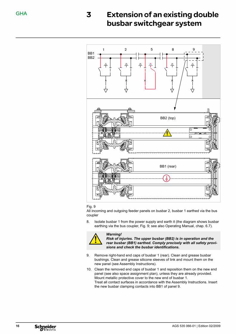
7. Reroute all outgoing feeders to busbar 2 (Fig. 9).
Preparation
BB1 BB2
GHA
16 AGS 535 066-01 | Edition 02/200916
3 Extension of an existing double busbar switchgear system
SS 2SS 1
1 2 5 8 9
BB2 (top)
BB1 (rear)
Fig. 9All incoming and outgoing feeder panels on busbar 2, busbar 1 earthed via the bus coupler
8. Isolate busbar 1 from the power supply and earth it (the diagram shows busbar earthing via the bus coupler, Fig. 9; see also Operating Manual, chap. 6.7).
Warning!Risk of injuries. The upper busbar (BB2) is in operation and the rear busbar (BB1) earthed. Comply precisely with all safety provi-sions and check the busbar identifications.
9. Remove right-hand end caps of busbar 1 (rear). Clean and grease busbar bushings. Clean and grease silicone sleeves of link and mount them on the new panel (see Assembly Instructions).
10. Clean the removed end caps of busbar 1 and reposition them on the new end panel (see also space assignment plan), unless they are already provided. Mount metallic protective cover to the new end of busbar 1. Treat all contact surfaces in accordance with the Assembly Instructions. Insert the new busbar clamping contacts into BB1 of panel 9.
BB1 BB2

GHA
17AGS 535 066-01 | Edition 02/2009 17
3 Extension of an existing double busbar switchgear system
11. Position new panel on the base frame in accordance with the space assign-ment plan, align it and screw-fasten it to the adjacent panel and the base frame (see Assembly Instructions).
12. Mount busbar connection for busbar 1 completely with clamping contacts (see Assembly Instructions) (Fig. 10).
SS2SS1
1 2 5 8 9
BB2 (top)
BB1 (rear)
Fig. 10– New panel lined-up on the right-hand end– Busbar 1 (rear) completely connected and ready to operate (protective cover on
busbar end not shown)– Busbar 2 (top) not yet connected
13. If applicable, mount further panels in accordance with item 11. Mount both busbar systems BB1 and BB2 completely to the new panels (see Assembly Instructions).
Line up new panel
BB1 BB2

GHA
18 AGS 535 066-01 | Edition 02/200918
3 Extension of an existing double busbar switchgear system
14. The further steps for assembly are to be performed in accordance with the As-sembly Instructions: – connect the earth bars – connect the low-voltage cables (ring lines, external customer cables
Commission extension panels: – comply with Assembly Instructions (Chapter 10) – check operating functions and interlocks of switching devices
Set extension panels to „EARTHED“ position (Fig. 11).
SS2SS1
1 2 5 8 9
Fig. 11New panel earthed, all incoming and outgoing feeder panels on busbar 1, busbar 2 earthed via the bus coupler
15. Reroute panels to BB1:
Warning!For safety reasons, all persons must be located in front of the switchgear during switching operations!
– Cancel BB1 earthing. – Switch bus coupler ON. – Reroute panels to BB1.
16. Isolate busbar 2 from the power supply and earth it (the diagram shows busbar earthing via the bus coupler, Fig. 11; see Operating Manual, chap. 6.7).
Warning!Risk of injuries. Now, the rear busbar (BB1) is in operation and the upper busbar (BB2) earthed. Comply precisely with all safety provisions and check the busbar identifications.
Remove busbar end caps of busbar 2 and clean and grease all busbar bushings. Clean and grease silicone link sleeve, insert it under preload and mount it to the right on the panel.
17. On the new panels, mount all upper busbar links of the BB2 completely in ac-cordance with the Assembly Instructions (Fig. 12).
BB1 BB2

GHA
19AGS 535 066-01 | Edition 02/2009 19
3 Extension of an existing double busbar switchgear system
SS2SS1
1 2 5 8 9
BB2 (top)
BB1 (rear)
Fig. 12New panel connected to the two busbars Busbar 1 in operation Busbar 2 still earthed, but ready to operate (protective covers on busbar end not shown)
18. Remount the removed busbar end cap on the new end panel (unless already provided). Mount metallic protective cover to the new busbar end. All the other assembly steps are to be performed in accordance with the As-sembly Instructions: – attach right-hand end plate and gap cover. – high-voltage terminals – final steps.
BB1 BB2
GHA
20 AGS 535 066-01 | Edition 02/2009
4 Replacement of a panel within a switchgear system
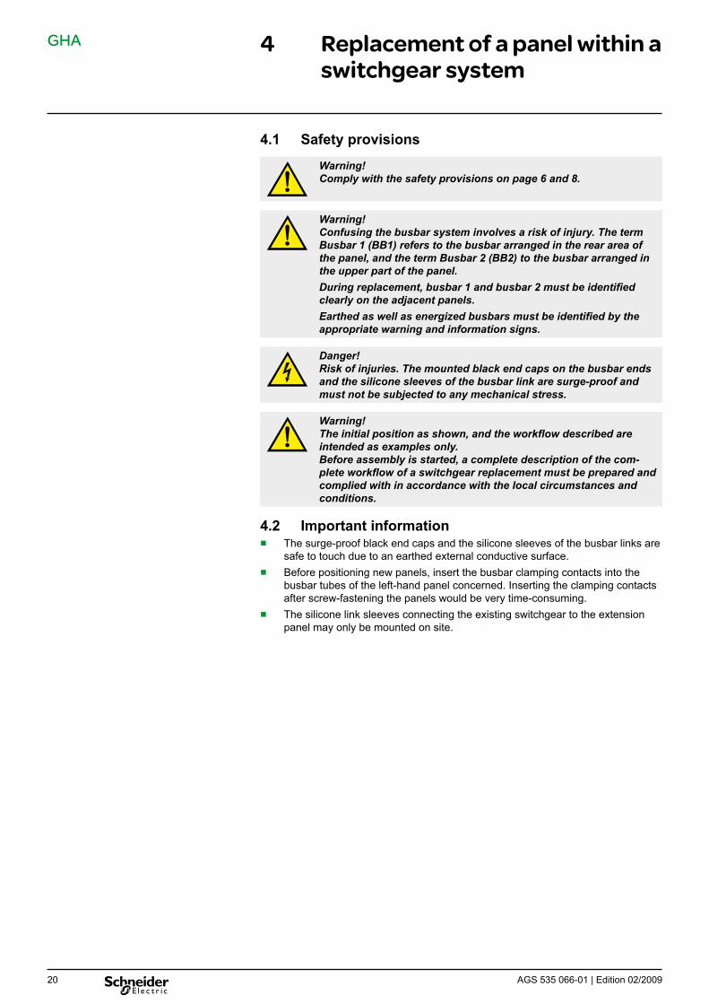
4.1 Safety provisions
Warning!Comply with the safety provisions on page 6 and 8.
Warning!Confusing the busbar system involves a risk of injury. The term Busbar 1 (BB1) refers to the busbar arranged in the rear area of the panel, and the term Busbar 2 (BB2) to the busbar arranged in the upper part of the panel.During replacement, busbar 1 and busbar 2 must be identified clearly on the adjacent panels.Earthed as well as energized busbars must be identified by the appropriate warning and information signs.
Danger!Risk of injuries. The mounted black end caps on the busbar ends and the silicone sleeves of the busbar link are surge-proof and must not be subjected to any mechanical stress.
Warning!The initial position as shown, and the workflow described are intended as examples only. Before assembly is started, a complete description of the com-plete workflow of a switchgear replacement must be prepared and complied with in accordance with the local circumstances and conditions.
4.2 Important information ■ The surge-proof black end caps and the silicone sleeves of the busbar links are
safe to touch due to an earthed external conductive surface. ■ Before positioning new panels, insert the busbar clamping contacts into the
busbar tubes of the left-hand panel concerned. Inserting the clamping contacts after screw-fastening the panels would be very time-consuming.
■ The silicone link sleeves connecting the existing switchgear to the extension panel may only be mounted on site.

GHA
21AGS 535 066-01 | Edition 02/2009 21
4 Replacement of a panel within a switchgear system
4.3 Initial situation ■ both busbar systems are operating ■ the incoming feeder panels are located at the appropriate end of the switchgear ■ one busbar system continues to operate alternately during the replacement ■ wall-mounting
SS2SS1
1 5 6 7 8 9
Fig. 13The diagram shows a 9-panel switchgear consisting of– 2 incoming feeder panels (panels 1 and 9)– bus coupler (panel 5)– 6 outgoing feeder panels (shown as an example: panels 6, 7 and 8)BB1 Busbar 1 (arranged at the rear of the panel)BB2 Busbar 2 (arranged at the top of the panel)
BB1 BB2

GHA
22 AGS 535 066-01 | Edition 02/200922
4 Replacement of a panel within a switchgear system
4.4 Fault in a busbar compartmentIn the following, a fault in the compartment of BB2 (upper busbar) of panel 7 (Fig. 14) is assumed.
SS2SS1
1 5 6 7 8 9
BB2 (top)
BB1 (rear)
Fig. 14Illustrated: Fault on busbar 2 of panel 7 – Outgoing feeder of panel 7 earthed – Busbar 2 isolated from power supply and earthed via the bus coupler Fault in the compartment of busbar BB2
1. Isolate the fault from the power supply. Circuit-breaker compartment: isolate outgoing feeder of panel from the power supply, and earth it (see Operating Manual) (Fig. 14). Busbar compartment: Isolate the relevant busbar - busbar 2 - from the power supply and earth it (the diagram shows busbar earthing via the bus coupler, Fig. 14; see also Operating Manual, chap. 6.7).
Warning!Risk of injuries. The rear busbar (BB1) is in operation and the upper busbar (BB2) earthed. Comply precisely with all safety provisions.
2. Inform the manufacturer.3. Depending on the damage situation, it must be decided whether to repair the
panel concerned, or whether to wait until a new panel is available on site.
BB1 BB2
GHA
23AGS 535 066-01 | Edition 02/2009 23
4 Replacement of a panel within a switchgear system
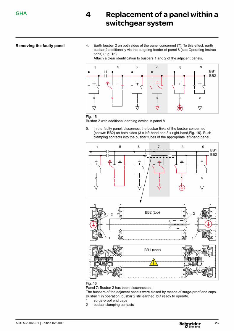
4. Earth busbar 2 on both sides of the panel concerned (7). To this effect, earth busbar 2 additionally via the outgoing feeder of panel 8 (see Operating Instruc-tions) (Fig. 15).Attach a clear identification to busbars 1 and 2 of the adjacent panels.
SS2SS1
1 5 6 7 8 9
Fig. 15Busbar 2 with additional earthing device in panel 8
5. In the faulty panel, disconnect the busbar links of the busbar concerned (shown: BB2) on both sides (3 x left-hand and 3 x right-hand,Fig. 16). Push clamping contacts into the busbar tubes of the appropriate left-hand panel.
SS2SS1
1 5 6 7 8 9
1 1
22 BB2 (top)
BB1 (rear)
Fig. 16Panel 7: Busbar 2 has been disconnected. The busbars of the adjacent panels were closed by means of surge-proof end caps. Busbar 1 in operation, busbar 2 still earthed, but ready to operate.1 surge-proof end caps2 busbar clamping contacts
Removing the faulty panel
BB1 BB2
BB1 BB2

GHA
24 AGS 535 066-01 | Edition 02/200924
4 Replacement of a panel within a switchgear system
6. Remove silicone sleeves of the busbar connections.7. Clean and grease the open busbar bushings on the adjacent panels and close
them using surge-proof end caps (Fig. 16, item 1). Left-hand adjacent panel: narrow end caps Right-hand adjacent panel: high end caps Thus, both sections of busbar 2 are ready to operate.
8. Reroute all outgoing feeder panels to BB2.
Warning!Risk of injury in case of operating errors! For safety reasons, all persons must be located in front of the switchgear during switching operations!
– Cancel both BB2 earthings. – Switch bus coupler ON. – Switch disconnectors in the incoming feeder panels to BB2. – Switch disconnectors in outgoing feeder panels - except those of the faulty
panel 7 – to BB2 (Fig. 17). – In the outgoing feeder panels, open the disconnectors for BB1. – In the incoming feeder panels, open the disconnectors for BB1. – Switch off the bus coupler.
SS2SS1
1 5 6 7 8 9
Fig. 17Both sections of busbar 2 are in operation
9. Earth BB1 on both sides of the panel concerned (shown in Fig. 18: busbar earthing through bus coupler and via outgoing feeder of panel 8, see also Oper-ating Manual, Chapter 6.7).
SS2SS1
1 5 6 7 8 9
Fig. 18Busbar 1 earthed via bus coupler (5). Mount additional earthing device to busbar 1 (panel 8). All other panels switched to busbar 2.
Warning!Risk of injuries. The upper busbar (BB2) is in operation and the rear busbar (BB1) is now earthed. Comply precisely with all safety provisions. Check busbar identification.
BB1 BB2
BB1 BB2
GHA
25AGS 535 066-01 | Edition 02/2009 25
4 Replacement of a panel within a switchgear system
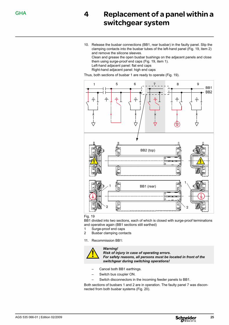
10. Release the busbar connections (BB1, rear busbar) in the faulty panel. Slip the clamping contacts into the busbar tubes of the left-hand panel (Fig. 19, item 2) and remove the silicone sleeves. Clean and grease the open busbar bushings on the adjacent panels and close them using surge-proof end caps (Fig. 19, item 1). Left-hand adjacent panel: flat end caps Right-hand adjacent panel: high end caps
Thus, both sections of busbar 1 are ready to operate (Fig. 19).
SS2SS1
1 5 6 7 8 9
11
2 2
BB2 (top)
BB1 (rear)
Fig. 19BB1 divided into two sections, each of which is closed with surge-proof terminations and operative again (BB1 sections still earthed)1 Surge-proof end caps2 Busbar clamping contacts
11. Recommission BB1:
Warning!Risk of injury in case of operating errors. For safety reasons, all persons must be located in front of the switchgear during switching operations!
– Cancel both BB1 earthings. – Switch bus coupler ON. – Switch disconnectors in the incoming feeder panels to BB1.
Both sections of busbars 1 and 2 are in operation. The faulty panel 7 was discon-nected from both busbar systems (Fig. 20).
BB1 BB2

GHA
26 AGS 535 066-01 | Edition 02/200926
4 Replacement of a panel within a switchgear system
SS2SS1
1 5 6 7 8 9
1 1
2
2
2
2
BB2 (top)
BB1 (rear)
Fig. 20Panel 7: Both busbars are disconnected. The busbars of the adjacent panels were closed by means of surge-proof end caps. Busbar 1 in operation, busbar 2 in opera-tion.1 Surge-proof end caps2 Busbar clamping contacts
12. Disconnect all the other panel connections: – panel screw fastenings to adjacent panels / base frame – earth conductor
The left-hand and right-hand switchgear sections must be connected suf-ficiently to the building earth (see Assembly Instructions, Chapter 4.9).
– low-voltage connectors and ring lines – high-voltage terminals
13. Remove panel.
14. On the new or repaired panel, treat the busbar contact areas and the clamping contacts in accordance with the Assembly Instructions. Insert the clamping contacts into the busbar tubes (Fig. 20, item 2) and reposition the panel on the base frame.
Insert new panel
BB1 BB2

GHA
27AGS 535 066-01 | Edition 02/2009 27
4 Replacement of a panel within a switchgear system
1
2 1
2
Fig. 21Releasing the busbar link1 Clamping contacts2 Surge-proof busbar end caps
BB1
BB2
GHA
28 AGS 535 066-01 | Edition 02/200928
4 Replacement of a panel within a switchgear system
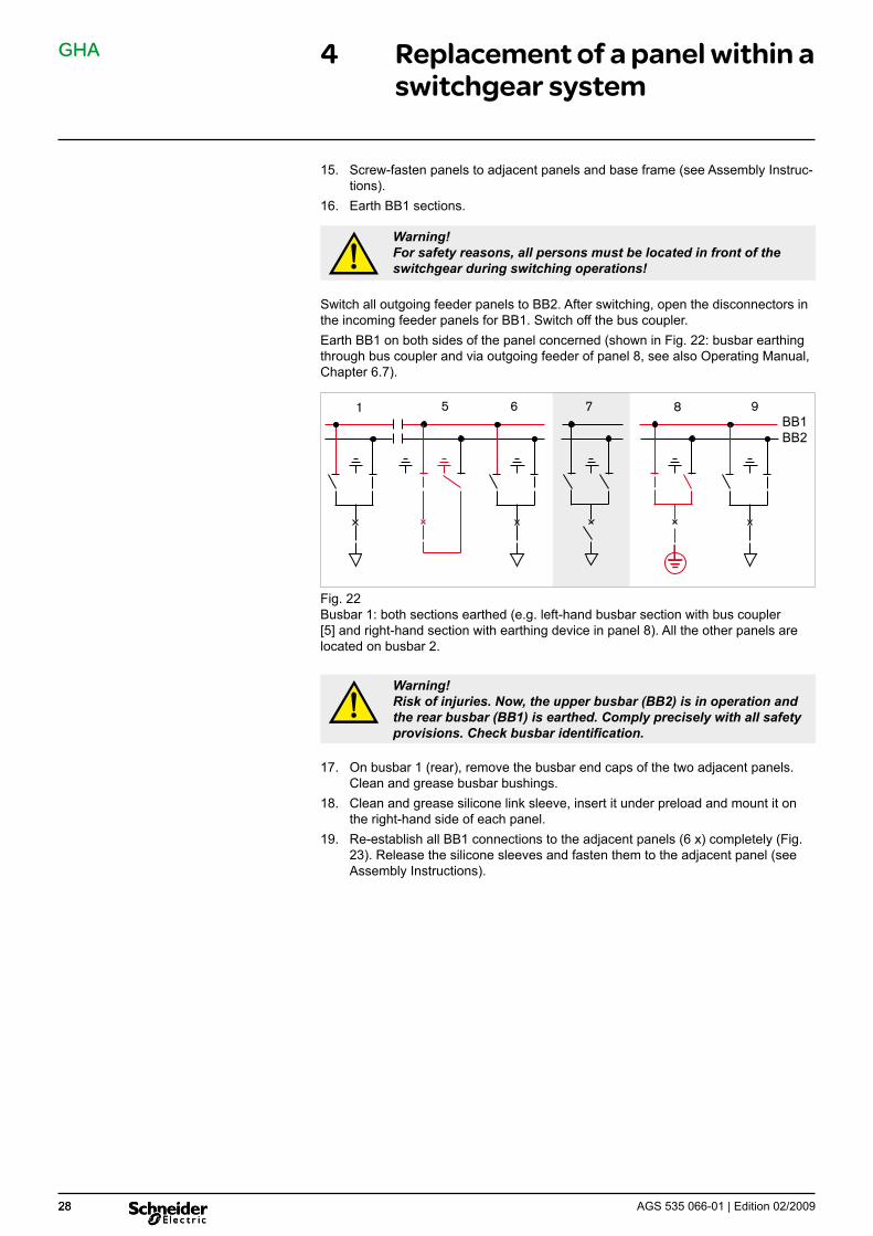
15. Screw-fasten panels to adjacent panels and base frame (see Assembly Instruc-tions).
16. Earth BB1 sections.
Warning!For safety reasons, all persons must be located in front of the switchgear during switching operations!
Switch all outgoing feeder panels to BB2. After switching, open the disconnectors in the incoming feeder panels for BB1. Switch off the bus coupler.Earth BB1 on both sides of the panel concerned (shown in Fig. 22: busbar earthing through bus coupler and via outgoing feeder of panel 8, see also Operating Manual, Chapter 6.7).
SS2SS1
1 5 6 7 8 9
Fig. 22Busbar 1: both sections earthed (e.g. left-hand busbar section with bus coupler [5] and right-hand section with earthing device in panel 8). All the other panels are located on busbar 2.
Warning!Risk of injuries. Now, the upper busbar (BB2) is in operation and the rear busbar (BB1) is earthed. Comply precisely with all safety provisions. Check busbar identification.
17. On busbar 1 (rear), remove the busbar end caps of the two adjacent panels. Clean and grease busbar bushings.
18. Clean and grease silicone link sleeve, insert it under preload and mount it on the right-hand side of each panel.
19. Re-establish all BB1 connections to the adjacent panels (6 x) completely (Fig. 23). Release the silicone sleeves and fasten them to the adjacent panel (see Assembly Instructions).
BB1 BB2

GHA
29AGS 535 066-01 | Edition 02/2009 29
4 Replacement of a panel within a switchgear system
SS2SS1
1 5 6 7 8 9
BB2 (top)
BB1 (rear)
Fig. 23Panel 7: busbar 1 with full continuity and ready to operate again, but still earthed.Busbar 2 in operation.
20. The further steps for assembly are to be performed in accordance with the Assembly Instructions: – connect the earth bars. – connect the low-voltage cables (ring lines, external customer cables).
Commission replacement panel: – comply with Assembly Instructions – check operating functions and interlocks of switching devices.
Set replacement panel to „EARTHED“ position (Fig. 24).Thus, busbar 1 is ready to operate again.
21. Reroute outgoing feeder panels to BB1 (Fig. 24):
BB1 BB2

GHA
30 AGS 535 066-01 | Edition 02/200930
4 Replacement of a panel within a switchgear system
Warning!Risk of injury in case of operating errors. For safety reasons, all persons must be located in front of the switchgear during switching operations!
– Cancel both BB1 earthings. – Switch bus coupler ON. – Switch disconnectors in the incoming feeder panels to BB1. – Switch disconnectors in the outgoing feeder panels to BB1 (Fig. 24). – In the outgoing feeder panels, open the disconnectors for BB2. – In the incoming feeder panels, open the disconnectors for BB2. – Switch off the bus coupler.
SS2SS1
1 5 6 7 8 9
BB2 (top)
BB1 (rear)
Fig. 24Replacement panel earthed, all outgoing feeder panels on busbar 1
BB1 BB2

GHA
31AGS 535 066-01 | Edition 02/2009 31
4 Replacement of a panel within a switchgear system
22. Earth BB2 on both sides of the panel concerned (shown in Fig. 25: busbar earthing through bus coupler and via outgoing feeder of panel 8, see also Oper-ating Manual, Chapter 6.7).
Warning!Risk of injuries. Now, the rear busbar (BB1) is in operation and the upper busbar (BB2) earthed. Comply precisely with all safety provisions. Check busbar identification.
SS2SS1
1 5 6 7 8 9
Fig. 25Busbar 2: both sections earthed (e.g. left-hand busbar section with bus coupler [5] and right-hand section with earthing device in panel 8). All the other panels are located on busbar 1.
23. On busbar 2 (top), remove the busbar end caps of the two adjacent panels. Clean and grease busbar bushings. Clean and grease silicone link sleeve, insert it under preload and mount it on the right-hand side of each panel. Re-establish all BB2 connections to the adjacent panels (6 x) completely. Re-lease the silicone sleeves and fasten them to the adjacent panel (see Assembly Instructions).
24. All the other assembly steps are to be performed in accordance with the As-sembly Instructions: – final steps – high-voltage terminals
Switch bus coupler ON. Thus, both busbars are operative again (Fig. 26).
BB1 BB2

GHA
32 AGS 535 066-01 | Edition 02/200932
4 Replacement of a panel within a switchgear system
SS2SS1
1 5 6 7 8 9
BB2 (top)
BB1 (rear)
Fig. 26Replacement of panel complete. New panel (7) inserted and both busbars with full continuity and in operation again
BB1 BB2
GHA
33AGS 535 066-01 | Edition 02/2009
5 Annex
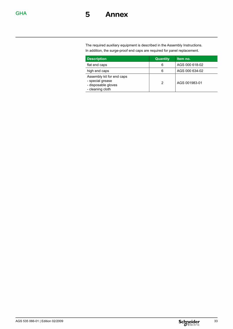
The required auxiliary equipment is described in the Assembly Instructions.In addition, the surge-proof end caps are required for panel replacement.
Description Quantity Item no.flat end caps 6 AGS 000 618-02
high end caps 6 AGS 000 634-02Assembly kit for end caps - special grease - disposable gloves - cleaning cloth
2 AGS 001983-01

Notes:


Schneider Electric35, rue Joseph MonierCS 3032392506 Rueil-Malmaison Cedex, France
RCS Nanterre 954 503 439Capital social 896 313 776 €www.schneider-electric.com AGS 535 066-01 | 02-2009
As our products are subject to continuous development, we reserve theright to make changes regarding the standards, illustrations and technicaldata described in this Technical Manual. For any requests, please contact the address given below.
Schneider Electric Sachsenwerk GmbHRathenaustrasse 2D-93055 Regensburg, Germany( +49 (0) 9 41 46 20-07 +49 (0) 9 41 46 20-418
© S
chne
ider
Ele
ctric
201
1 –
All
right
s re
serv
ed to
this
tech
nica
l man
ual.
Rep
rodu
ctio
n an
d m
akin
g av
aila
ble
of th
is te
chni
cal m
anua
l, or
ext
ract
s, to
third
par
ties
are
proh
ibite
d.
Onl
y in
tegr
al re
prod
uctio
n of
this
tech
nica
l man
ual i
s pe
rmitt
ed w
ith th
e w
ritte
n pe
rmis
sion
from
Sch
neid
er E
lect
ric. E
lect
roni
c co
pies
in e
.g. P
DF-
form
at o
r sca
nned
ver
sion
ha
ve th
e st
atus
“for
info
rmat
ion
only
” . T
he o
nly
valid
ver
sion
of t
his
tech
nica
l man
ual i
s al
way
s en
clos
ed d
irect
ly to
the
prod
uct i
n qu
estio
n by
the
fact
ory.