G7L15%/-20% for AC rated current and ±15% for DC coil resistance. 2. The inductances shown above...
13
1 G 7 L G7L Power Relay A High-capacity, High-dielectric-strength Relay Compatible with Momentary Voltage Drops • No contact chattering for momentary voltage drops up to 50% of rated voltage. • Wide-range AC-activated coil that handles 100 to 120 or 200 to 240 VAC at either 50 or 60 Hz. • Miniature size for maximum switching power, particularly for inductive loads. • Flame-resistance materials (UL94V-0-qualifying) used for all insulation material. • Quick-connect, screw, and PCB terminals, and DIN track mounting available. • Conforms to UL, CSA, TUV and meets IEC950. • Safety design with contact gap of 3 mm. ■List of E-bracket Mounting Models RoHS Compliant Mounting E-brackets DIN Track Mounting Adapter Front-connecting Socket Terminal Contact form Model Test button Quick- connect terminals SPST-NO G7L-1A-T − { { { Note. Accessories: E-bracket (R99-07), Adapter (P7LF-D), Front-connecting socket (P7LF-06) and Cover (P7LF-C) sold separately. G7L-1A-TJ With test button { { { DPST-NO G7L-2A-T − { { { G7L-2A-TJ With test button { { { Screw terminals SPST-NO G7L-1A-B − { { − G7L-1A-BJ With test button { { − DPST-NO G7L-2A-B − { { − G7L-2A-BJ With test button { { − Note. Accessories: E-bracket, Adapter, Front-connecting socket and Cover sold separately. ■Application Examples x Compressors for air conditioners and heater switching controllers. x Switching controllers for power tools or motors. x Power controllers for water heaters. x Power controllers for dryers. x Lamp controls, motor drivers, and power supply switching in copy machines, facsimile machines, and other office equipment. x Lighting controllers. x Power controllers for packers or food processing equipment. x Magnetron control in microwaves. x Power controllers for Uninterruptible Power Supply (UPS) ■Model Number Legend G7L- @@ - @@@ —— ——— 12 345 1. Number of Poles 1: 1 pole 2: 2 poles 2. Contact Form A: @PST-NO 3. Terminal Shape T: Quick connect terminals (#250) B: Screw terminals P: PCB terminals 4. Mounting Construction Blank: E-bracket UB : Upper bracket 5. Special Functions J : With test button ■Model Configuration Terminal Quick-connect terminals Screw terminals PCB terminals Classification Contact form E-bracket mounting (E-bracket is sold separately) − SPST-NO G7L-1A-T G7L-1A-B − DPST-NO G7L-2A-T G7L-2A-B − With test button SPST-NO G7L-1A-TJ G7L-1A-BJ − DPST-NO G7L-2A-TJ G7L-2A-BJ − Upper bracket mounting − SPST-NO G7L-1A-TUB G7L-1A-BUB − DPST-NO G7L-2A-TUB G7L-2A-BUB − With test button SPST-NO G7L-1A-TUBJ G7L-1A-BUBJ − DPST-NO G7L-2A-TUBJ G7L-2A-BUBJ − PCB mounting − SPST-NO − − G7L-1A-P DPST-NO − − G7L-2A-P
Transcript of G7L15%/-20% for AC rated current and ±15% for DC coil resistance. 2. The inductances shown above...

1
G7L
G7LPower Relay
A High-capacity, High-dielectric-strength Relay Compatible with Momentary Voltage Drops• No contact chattering for momentary voltage drops up to 50% of
rated voltage.• Wide-range AC-activated coil that handles 100 to 120 or 200 to
240 VAC at either 50 or 60 Hz.• Miniature size for maximum switching power, particularly for
inductive loads.• Flame-resistance materials (UL94V-0-qualifying) used for all
insulation material.• Quick-connect, screw, and PCB terminals, and DIN track
mounting available.• Conforms to UL, CSA, TUV and meets IEC950.• Safety design with contact gap of 3 mm.
■List of E-bracket Mounting Models
RoHS Compliant
Mounting E-brackets DIN Track Mounting Adapter
Front-connecting Socket
TerminalContact
form Model Test button
Quick-connect terminals
SPST-NOG7L-1A-T −
Note. Accessories: E-bracket (R99-07), Adapter (P7LF-D), Front-connecting socket (P7LF-06) and Cover (P7LF-C) sold separately.
G7L-1A-TJ With test button
DPST-NOG7L-2A-T −G7L-2A-TJ With test button
Screw terminals
SPST-NOG7L-1A-B − −G7L-1A-BJ With test button −
DPST-NOG7L-2A-B − −G7L-2A-BJ With test button −
Note. Accessories: E-bracket, Adapter, Front-connecting socket and Cover sold separately.
■Application Examples
Compressors for air conditioners and heater switching controllers.Switching controllers for power tools or motors.Power controllers for water heaters.Power controllers for dryers.Lamp controls, motor drivers, and power supply switching in copy machines, facsimile machines, and other office equipment.Lighting controllers.Power controllers for packers or food processing equipment.Magnetron control in microwaves.Power controllers for Uninterruptible Power Supply (UPS)
■Model Number LegendG7L-@@ -@@@
— — — — —1 2 3 4 5
1. Number of Poles1: 1 pole2: 2 poles
2. Contact FormA: @PST-NO
3. Terminal ShapeT: Quick connect
terminals (#250)B: Screw terminalsP: PCB terminals
4. Mounting ConstructionBlank: E-bracketUB : Upper bracket
5. Special FunctionsJ : With test button
■Model ConfigurationTerminal Quick-connect
terminals Screw terminals PCB terminals
Classification Contact formE-bracket mounting (E-bracket is sold separately)
− SPST-NO G7L-1A-T G7L-1A-B −DPST-NO G7L-2A-T G7L-2A-B −
With test button
SPST-NO G7L-1A-TJ G7L-1A-BJ −DPST-NO G7L-2A-TJ G7L-2A-BJ −
Upper bracket mounting
− SPST-NO G7L-1A-TUB G7L-1A-BUB −DPST-NO G7L-2A-TUB G7L-2A-BUB −
With test button
SPST-NO G7L-1A-TUBJ G7L-1A-BUBJ −DPST-NO G7L-2A-TUBJ G7L-2A-BUBJ −
PCB mounting − SPST-NO − − G7L-1A-PDPST-NO − − G7L-2A-P
2
G7L Power Relay
G7L
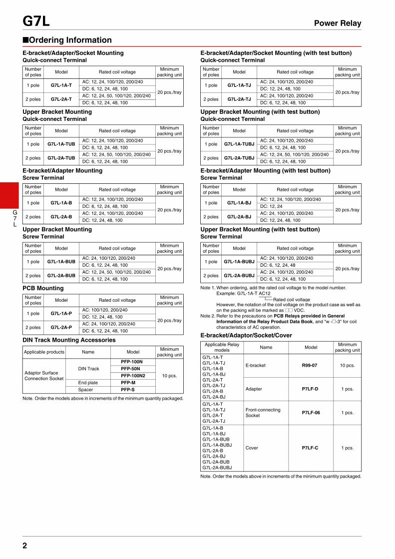
■Ordering InformationE-bracket/Adapter/Socket MountingQuick-connect Terminal
Upper Bracket MountingQuick-connect Terminal
E-bracket/Adapter MountingScrew Terminal
Upper Bracket MountingScrew Terminal
PCB Mounting
DIN Track Mounting Accessories
Note. Order the models above in increments of the minimum quantity packaged.
E-bracket/Adapter/Socket Mounting (with test button)Quick-connect Terminal
Upper Bracket Mounting (with test button)Quick-connect Terminal
E-bracket/Adapter Mounting (with test button)Screw Terminal
Upper Bracket Mounting (with test button)Screw Terminal
Note 1. When ordering, add the rated coil voltage to the model number. Example: G7L-1A-T AC12
However, the notation of the coil voltage on the product case as well as on the packing will be marked as @@ VDC.
Note 2. Refer to the precautions on PCB Relays provided in General Information of the Relay Product Data Book, and "w -@-3" for coil characteristics of AC operation.
E-bracket/Adaptor/Socket/Cover
Note. Order the models above in increments of the minimum quantity packaged.
Number of poles Model Rated coil voltage Minimum
packing unit
1 pole G7L-1A-TAC: 12, 24, 100/120, 200/240
20 pcs./trayDC: 6, 12, 24, 48, 100
2 poles G7L-2A-TAC: 12, 24, 50, 100/120, 200/240 DC: 6, 12, 24, 48, 100
Number of poles Model Rated coil voltage Minimum
packing unit
1 pole G7L-1A-TUBAC: 12, 24, 100/120, 200/240
20 pcs./trayDC: 6, 12, 24, 48, 100
2 poles G7L-2A-TUBAC: 12, 24, 50, 100/120, 200/240DC: 6, 12, 24, 48, 100
Number of poles Model Rated coil voltage Minimum
packing unit
1 pole G7L-1A-BAC: 12, 24, 100/120, 200/240
20 pcs./trayDC: 6, 12, 24, 48, 100
2 poles G7L-2A-BAC: 12, 24, 100/120, 200/240DC: 12, 24, 48, 100
Number of poles Model Rated coil voltage Minimum
packing unit
1 pole G7L-1A-BUBAC: 24, 100/120, 200/240
20 pcs./trayDC: 6, 12, 24, 48, 100
2 poles G7L-2A-BUBAC: 12, 24, 50, 100/120, 200/240DC: 6, 12, 24, 48, 100
Number of poles Model Rated coil voltage Minimum
packing unit
1 pole G7L-1A-PAC: 100/120, 200/240
20 pcs./trayDC: 12, 24, 48, 100
2 poles G7L-2A-PAC: 24, 100/120, 200/240DC: 6, 12, 24, 48, 100
Applicable products Name Model Minimum packing unit
Adaptor Surface Connection Socket
DIN TrackPFP-100N
10 pcs.PFP-50NPFP-100N2
End plate PFP-MSpacer PFP-S
Number of poles Model Rated coil voltage Minimum
packing unit
1 pole G7L-1A-TJAC: 24, 100/120, 200/240
20 pcs./trayDC: 12, 24, 48, 100
2 poles G7L-2A-TJAC: 24, 100/120, 200/240DC: 6, 12, 24, 48, 100
Number of poles Model Rated coil voltage Minimum
packing unit
1 pole G7L-1A-TUBJAC: 24, 100/120, 200/240
20 pcs./trayDC: 6, 12, 24, 48, 100
2 poles G7L-2A-TUBJAC: 12, 24, 50, 100/120, 200/240DC: 6, 12, 24, 48, 100
Number of poles Model Rated coil voltage Minimum
packing unit
1 pole G7L-1A-BJAC: 12, 24, 100/120, 200/240
20 pcs./trayDC: 12, 24
2 poles G7L-2A-BJAC: 24, 100/120, 200/240DC: 12, 24, 48, 100
Number of poles Model Rated coil voltage Minimum
packing unit
1 pole G7L-1A-BUBJAC: 24, 100/120, 200/240
20 pcs./trayDC: 6, 12, 24, 48
2 poles G7L-2A-BUBJAC: 24, 100/120, 200/240DC: 6, 12, 24, 48, 100
Applicable Relay models Name Model Minimum
packing unit
G7L-1A-TG7L-1A-TJG7L-1A-BG7L-1A-BJG7L-2A-TG7L-2A-TJG7L-2A-BG7L-2A-BJ
E-bracket R99-07 10 pcs.
Adapter P7LF-D 1 pcs.
G7L-1A-TG7L-1A-TJG7L-2A-TG7L-2A-TJ
Front-connecting Socket P7LF-06 1 pcs.
G7L-1A-BG7L-1A-BJG7L-1A-BUBG7L-1A-BUBJG7L-2A-BG7L-2A-BJG7L-2A-BUBG7L-2A-BUBJ
Cover P7LF-C 1 pcs.
Rated coil voltage
3
G7L Power Relay
G7L
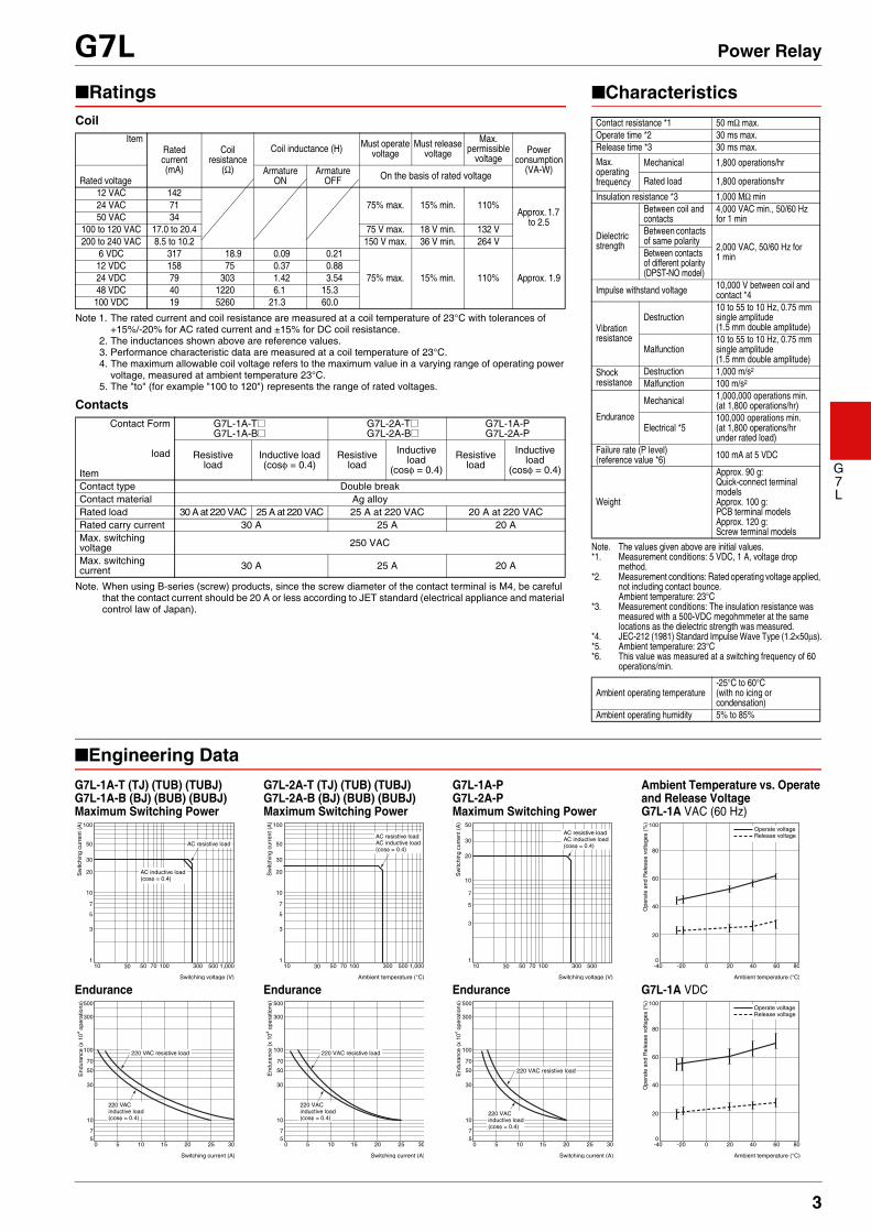
■Engineering DataG7L-1A-T (TJ) (TUB) (TUBJ)G7L-1A-B (BJ) (BUB) (BUBJ)Maximum Switching Power
G7L-2A-T (TJ) (TUB) (TUBJ)G7L-2A-B (BJ) (BUB) (BUBJ)Maximum Switching Power
G7L-1A-P G7L-2A-P Maximum Switching Power
Ambient Temperature vs. Operate and Release VoltageG7L-1A VAC (60 Hz)
Endurance Endurance Endurance G7L-1A VDC
■Characteristics
Note. The values given above are initial values.*1. Measurement conditions: 5 VDC, 1 A, voltage drop
method.*2. Measurement conditions: Rated operating voltage applied,
not including contact bounce.Ambient temperature: 23°C
*3. Measurement conditions: The insulation resistance was measured with a 500-VDC megohmmeter at the same locations as the dielectric strength was measured.
*4. JEC-212 (1981) Standard Impulse Wave Type (1.2×50μs).*5. Ambient temperature: 23°C*6. This value was measured at a switching frequency of 60
operations/min.
Contact resistance *1 50 mΩ max.Operate time *2 30 ms max.Release time *3 30 ms max.Max. operating frequency
Mechanical 1,800 operations/hr
Rated load 1,800 operations/hr
Insulation resistance *3 1,000 MΩ min
Dielectric strength
Between coil and contacts
4,000 VAC min., 50/60 Hz for 1 min
Between contacts of same polarity 2,000 VAC, 50/60 Hz for
1 minBetween contacts of different polarity (DPST-NO model)
Impulse withstand voltage 10,000 V between coil and contact *4
Vibration resistance
Destruction10 to 55 to 10 Hz, 0.75 mm single amplitude (1.5 mm double amplitude)
Malfunction10 to 55 to 10 Hz, 0.75 mm single amplitude (1.5 mm double amplitude)
Shock resistance
Destruction 1,000 m/s2
Malfunction 100 m/s2
Endurance
Mechanical 1,000,000 operations min. (at 1,800 operations/hr)
Electrical *5100,000 operations min. (at 1,800 operations/hr under rated load)
Failure rate (P level) (reference value *6) 100 mA at 5 VDC
Weight
Approx. 90 g: Quick-connect terminal modelsApprox. 100 g:PCB terminal modelsApprox. 120 g:Screw terminal models
Ambient operating temperature-25°C to 60°C (with no icing or condensation)
Ambient operating humidity 5% to 85%
■RatingsCoil
Note 1. The rated current and coil resistance are measured at a coil temperature of 23°C with tolerances of +15%/-20% for AC rated current and ±15% for DC coil resistance.
2. The inductances shown above are reference values.3. Performance characteristic data are measured at a coil temperature of 23°C.4. The maximum allowable coil voltage refers to the maximum value in a varying range of operating power
voltage, measured at ambient temperature 23°C.5. The "to" (for example "100 to 120") represents the range of rated voltages.
Contacts
Note. When using B-series (screw) products, since the screw diameter of the contact terminal is M4, be careful that the contact current should be 20 A or less according to JET standard (electrical appliance and material control law of Japan).
ItemRated current(mA)
Coil resistance
(Ω)
Coil inductance (H) Must operate voltage
Must release voltage
Max. permissible
voltagePower
consumption(VA-W)
Rated voltageArmature
ONArmature
OFF On the basis of rated voltage
12 VAC 14275% max. 15% min. 110%
Approx. 1.7 to 2.5
24 VAC 7150 VAC 34
100 to 120 VAC 17.0 to 20.4 75 V max. 18 V min. 132 V200 to 240 VAC 8.5 to 10.2 150 V max. 36 V min. 264 V
6 VDC 317 18.9 0.09 0.21
75% max. 15% min. 110% Approx. 1.912 VDC 158 75 0.37 0.8824 VDC 79 303 1.42 3.5448 VDC 40 1220 6.1 15.3100 VDC 19 5260 21.3 60.0
Contact Form
load
Item
G7L-1A-T@G7L-1A-B@
G7L-2A-T@G7L-2A-B@
G7L-1A-PG7L-2A-P
Resistive load
Inductive load(cosφ = 0.4)
Resistive load
Inductive load
(cosφ = 0.4)Resistive
loadInductive
load(cosφ = 0.4)
Contact type Double breakContact material Ag alloyRated load 30 A at 220 VAC 25 A at 220 VAC 25 A at 220 VAC 20 A at 220 VACRated carry current 30 A 25 A 20 AMax. switching voltage 250 VAC
Max. switching current 30 A 25 A 20 A
10 30 50 70 100 300 500 1,000
Switching voltage (V)
100
30
10
20
50
1
3
5
7
Sw
itchi
ng c
urre
nt (
A)
AC inductive load(cosφ = 0.4)
AC resistive load
10 30 50 70 100 300 500 1,000
Ambient temperature (°C)
100
30
10
20
50
1
3
5
7
Sw
itchi
ng c
urre
nt (
A)
AC resistive loadAC inductive load(cosφ = 0.4)
10 30 50 70 100 300 500
Switching voltage (V)
50
20
10
30
1
3
5
7
Sw
itchi
ng c
urre
nt (
A)
AC resistive loadAC inductive load(cosφ = 0.4)
-40 -20 0 20 40 60 80
Ambient temperature (°C)
100
80
60
40
20
0
Ope
rate
and
Rel
ease
vol
tage
s (%
)
Operate voltageRelease voltage
0 5 10 15 20 25 30
Switching current (A)
500
300
100
70
50
30
10
57
220 VAC resistive load
End
uran
ce (
x 10
4 ope
ratio
ns)
220 VAC inductive load(cosφ = 0.4)
0 5 10 15 20 25 30
Switching current (A)
500
300
100
70
50
30
10
57
220 VAC resistive load
End
uran
ce (
x 10
4 ope
ratio
ns)
220 VAC inductive load(cosφ = 0.4)
0 5 10 15 20 25 30
Switching current (A)
500
300
100
70
50
30
10
57
220 VAC resistive load
End
uran
ce (
x 10
4 ope
ratio
ns)
220 VACinductive load(cosφ = 0.4)
-40 -20 0 20 40 60 80
Ambient temperature (°C)
100
80
60
40
20
0
Ope
rate
and
Rel
ease
vol
tage
s (%
)
Operate voltageRelease voltage
4
G7L Power Relay
G7L
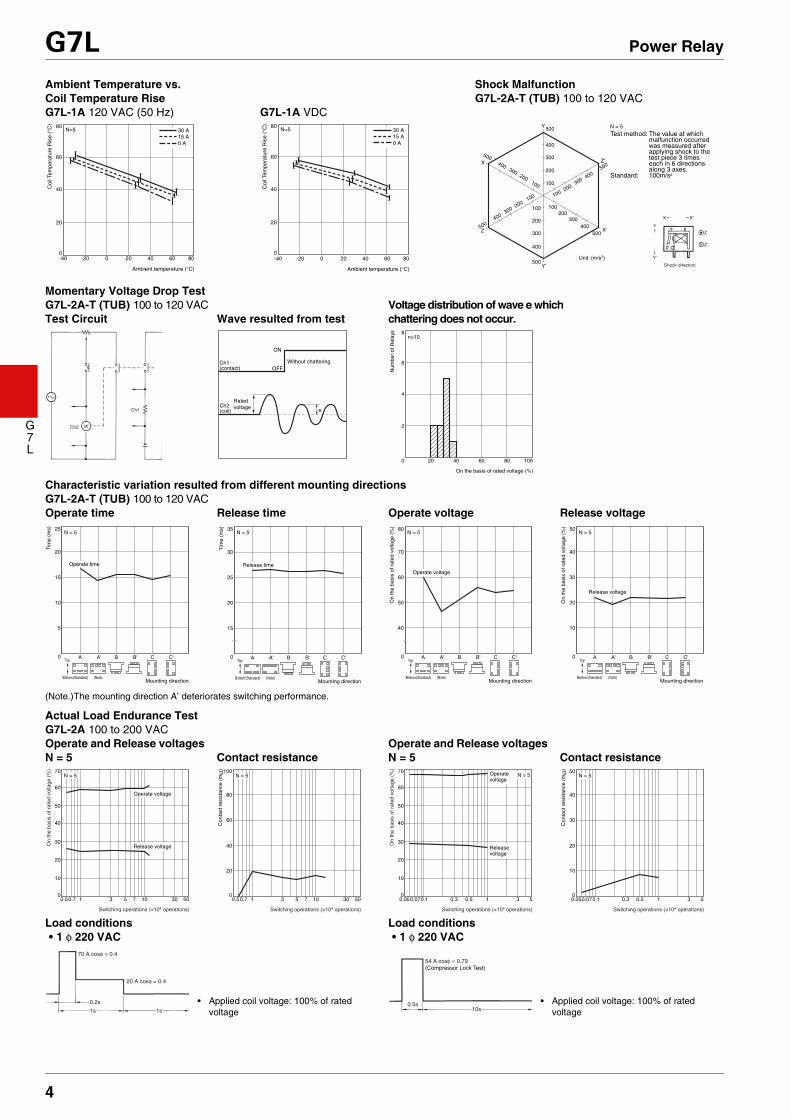
Ambient Temperature vs. Coil Temperature RiseG7L-1A 120 VAC (50 Hz) G7L-1A VDC
Shock MalfunctionG7L-2A-T (TUB) 100 to 120 VAC
Momentary Voltage Drop TestG7L-2A-T (TUB) 100 to 120 VACTest Circuit Wave resulted from test
Voltage distribution of wave e which chattering does not occur.
Characteristic variation resulted from different mounting directionsG7L-2A-T (TUB) 100 to 120 VACOperate time Release time Operate voltage Release voltage
(Note.)The mounting direction A’ deteriorates switching performance.
Actual Load Endurance TestG7L-2A 100 to 200 VACOperate and Release voltages N = 5 Contact resistance
Operate and Release voltages N = 5 Contact resistance
Load conditions Load conditions• 1 φ 220 VAC • 1 φ 220 VAC
-40
Ambient temperature (°C)
80
60
40
20
0
0 A15 A30 AN=5
Coi
l Tem
pera
ture
Ris
e (°
C)
-20 0 20 40 60 80
80
60
40
20
0-40
Ambient temperature (°C)
0 A15 A30 AN=5
Coi
l Tem
pera
ture
Ris
e (°
C)
-20 0 20 40 60 80
Y
X Z'
X'Z
100
100200
300400
500
100
300
400
500
200
100
300
400
500
200
500
300
200
100
400
100
200
300
400
500
200
300
400
500
Y'
Unit: (m/s2)
N = 5
Test method: The value at which malfunction occurred was measured after applying shock to the test piece 3 times each in 6 directions along 3 axes.
Standard: 100m/s2
Shock direction
X
Y
Z
Z'
Y'
X'
Ch2
Ch1
Ch1
ON
OFF(contact)
Ch2(coil)
Rated voltage
Without chattering
e
4020 60 80 100
On the basis of rated voltage (%)
8
6
4
2
0
Num
ber
of R
elay
s
n=10
25
20
15
10
5
0
Tim
e (m
s)
ATop
Bottom (Standard)Mounting direction
(Note)
A' B B' C C'
N = 5
Operate time
Tim
e (m
s) 35
30
25
20
15
0 ATop
Bottom(Standard)Mounting direction
(Note)
A' B B' C C'
N = 5
Release time
80
70
60
50
40
0
On
the
basi
s of
rat
ed v
olta
ge (
%)
ATop
Bottom(Standard)Mounting direction
(Note)
A' B B' C C'
N = 5
Operate voltage
50
40
30
20
10
0
On
the
basi
s of
rat
ed v
olta
ge (
%)
ATop
Bottom(Standard)Mounting direction
(Note)
A' B B' C C'
N = 5
Release voltage
0.70.5 1 3 5 7 10 30 50
Switching operations (×104 operations)
70
60
50
40
30
20
10
0
On
the
basi
s of
rat
ed v
olta
ge (
%)
Operate voltage
Release voltage
N = 5
0.70.5 1 3 5 7 10 30 50
100
80
60
40
20
0
Con
tact
res
ista
nce
(mΩ
)
N = 5
Switching operations (×104 operations)
0.070.05 0.1 0.3 0.5 1 3 5
70
60
50
40
30
20
10
0
On
the
basi
s of
rat
ed v
olta
ge (
%)
Operate voltage
Release voltage
N = 5
Switching operations (×104 operations)
0.070.05 0.1 0.3 0.5 1 3 5
50
40
30
20
10
0
Con
tact
res
ista
nce
(mΩ
)
N = 5
Switching operations (×104 operations)
70 A cosφ = 0.4
20 A cosφ = 0.4
0.2s
1s 1s
• Applied coil voltage: 100% of rated voltage
54 A cosφ = 0.79(Compressor Lock Test)
0.5s10s
• Applied coil voltage: 100% of rated voltage

5
G7L Power Relay
G7L
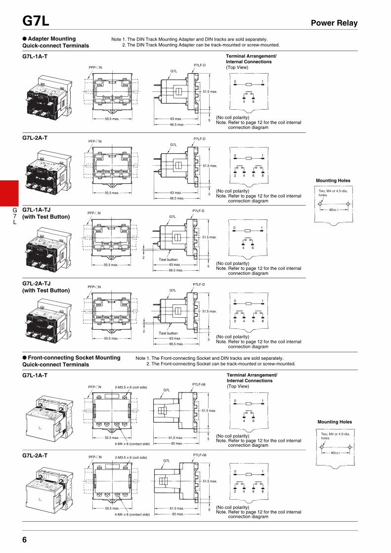
■Dimensions● E-bracket MountingQuick-connect Terminals
G7L-2A 100 to 200 VACOperate and Release voltages N = 5 Contact resistance
Operate and Release voltages N = 5 Contact resistance
Load conditions Load conditions• 1 φ 220 VAC • 1 φ 220 VAC
0.70.5 1 3 5 10 30 50
Switching operations (×102 operations)
70
60
50
40
30
20
10
0
On
the
basi
s of
rat
ed v
olta
ge (
%)
Operate voltage
Release voltage
N = 5
0.70.5 1 3 5 10 30 50
50
40
30
20
10
0C
onta
ct r
esis
tanc
e (m
Ω)
N = 5
Switching operations (×102 operations)
0.70.5 1 3 5 10 30 50
70
60
50
40
30
20
10
0
On
the
basi
s of
rat
ed v
olta
ge (
%)
Operate voltage
Release voltage
N = 5
Switching operations (×102 operations)
0.70.5 1 3 5 10 30 50
50
40
30
20
10
0
Con
tact
res
ista
nce
(mΩ
)
N = 5
Switching operations (×102 operations)
25 A cosφ = 1
2s 8s• Applied coil voltage: 75% of rated
voltage
70 A cosφ = 0.4
20 A cosφ = 0.4
0.2s
2s 8s
• Applied coil voltage: 75% of rated voltage
Note. E-brackets are sold separately.
Two, 4.5-dia. hole or M4 tapped holes
11
52.5 max.33.5 max.
53 max.
0 1
4 6
0.8
50.5 max.6.35
11
52.5 max.
33.5 max.
53 max.
0 1
4 6
40±0.1
0.8
250.5 max.6.35
11
52.5 max.
33.5 max.
53 max.
0 1
42 6 8
0.8
250.5 max.6.35
11
52.5 max.
33.5 max.
53 max.
0 1
42 6 8
0.8
50.5 max.6.35
Test button
Test button
G7L-1A-T Terminal Arrangement/Internal Connections(Top View)
Mounting Holes
(No coil polarity)Note. Refer to page 12 for the coil internal
connection diagram
G7L-2A-T
(No coil polarity)Note. Refer to page 12 for the coil internal
connection diagram
G7L-2A-T
G7L-1A-TJ(with Test Button)
(No coil polarity)Note. Refer to page 12 for the coil internal
connection diagram
G7L-2A-TJ(with Test Button)
(No coil polarity)Note. Refer to page 12 for the coil internal
connection diagram
6
G7L Power Relay
G7L
● Adapter MountingQuick-connect Terminals
● Front-connecting Socket MountingQuick-connect Terminals
Note 1. The DIN Track Mounting Adapter and DIN tracks are sold separately.2. The DIN Track Mounting Adapter can be track-mounted or screw-mounted.
Test button
Test button
Two, M4 or 4.5-dia. holes
55.5 max.
55.5 max.
63 max.
51.5 max.
66.5 max.
63 max.
51.5 max.
66.5 max.
PFP-@N
PFP-@N
G7L
G7L
P7LF-D
P7LF-D
40±0.1
0 1
4
5
5
5
2
2
5
6
0 1
42 6 8
55.5 max.
55.5 max.
63 max.
51.5 max.
66.5 max.
63 max.
51.5 max.
66.5 max.
PFP-@N
PFP-@N
G7L
G7L
P7LF-D
P7LF-D
0 1
4 6
0 1
42 6 8
G7L-1A-T Terminal Arrangement/Internal Connections(Top View)
Mounting Holes
(No coil polarity)Note. Refer to page 12 for the coil internal
connection diagram
(No coil polarity)Note. Refer to page 12 for the coil internal
connection diagram
G7L-2A-T
G7L-1A-TJ(with Test Button)
(No coil polarity)Note. Refer to page 12 for the coil internal
connection diagram
G7L-2A-TJ(with Test Button)
(No coil polarity)Note. Refer to page 12 for the coil internal
connection diagram
Note 1. The Front-connecting Socket and DIN tracks are sold separately.2. The Front-connecting Socket can be track-mounted or screw-mounted.
Two, M4 or 4.5-dia. holes
51.5 max.
61.5 max.55.5 max.
65 max.
51.5 max.
61.5 max.55.5 max.
65 max.
PFP-@N 2-M3.5 × 6 (coil side)
4-M4 × 8 (contact side)
2-M3.5 × 6 (coil side)
4-M4 × 8 (contact side)
G7L
P7LF-06
PFP-@NG7L
P7LF-0640±0.1
0 1
4
5
5
6
0 1
42 6 8
G7L-1A-T Terminal Arrangement/Internal Connections(Top View)
Mounting Holes
(No coil polarity)Note. Refer to page 12 for the coil internal
connection diagram
(No coil polarity)Note. Refer to page 12 for the coil internal
connection diagram
G7L-2A-T
7
G7L Power Relay
G7L
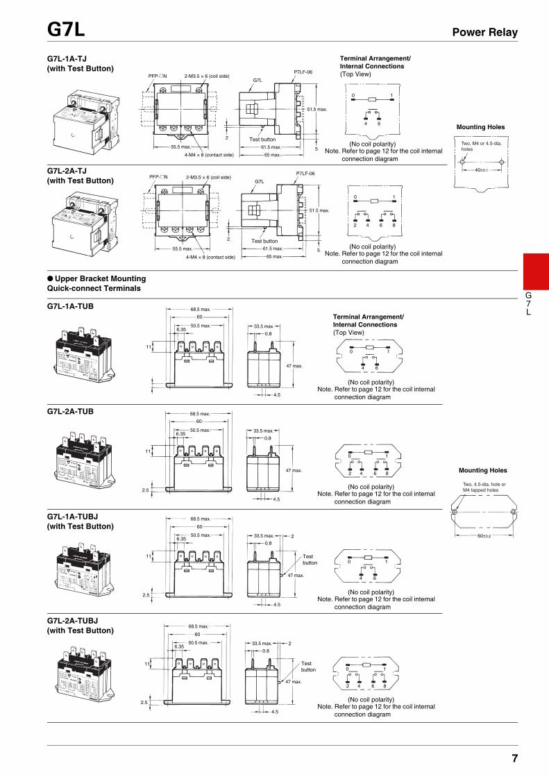
● Upper Bracket MountingQuick-connect Terminals
51.5 max.
61.5 max.55.5 max.
65 max.
51.5 max.
61.5 max.55.5 max.
65 max.
PFP-@N 2-M3.5 × 6 (coil side)
4-M4 × 8 (contact side)
2-M3.5 × 6 (coil side)
4-M4 × 8 (contact side)
G7L
P7LF-06
PFP-@NG7L
P7LF-06
0 1
4
5
5
2
2
6
0 1
42 6 8
Test button
Test button
Two, M4 or 4.5-dia. holes
40±0.1
G7L-1A-TJ(with Test Button)
Terminal Arrangement/Internal Connections(Top View)
Mounting Holes
Note. Refer to page 12 for the coil internal connection diagram
G7L-2A-TJ(with Test Button)
(No coil polarity)
Note. Refer to page 12 for the coil internal connection diagram
(No coil polarity)
Two, 4.5-dia. hole or M4 tapped holes
11
4.5
68.5 max.
33.5 max.
47 max.
0 1
4 6
0 1
42 6 8
0.8
50.5 max.6.35
60
11
2.5
4.5
68.5 max.
33.5 max.
47 max.
0.8
50.5 max.6.35
60
11
2.5
4.5
68.5 max.
33.5 max.
47 max.
0 1
4 6
0 1
42 6 8
0.8
2
2
50.5 max.6.35
60
11
2.5
4.5
68.5 max.
33.5 max.
47 max.
0.8
50.5 max.6.35
60
60±0.2
Test button
Test button
G7L-1A-TUBTerminal Arrangement/Internal Connections(Top View)
Mounting Holes
G7L-2A-TUB
G7L-1A-TUBJ(with Test Button)
G7L-2A-TUBJ(with Test Button)
Note. Refer to page 12 for the coil internal connection diagram
(No coil polarity)
Note. Refer to page 12 for the coil internal connection diagram
(No coil polarity)
Note. Refer to page 12 for the coil internal connection diagram
(No coil polarity)
Note. Refer to page 12 for the coil internal connection diagram
(No coil polarity)
8
G7L Power Relay
G7L
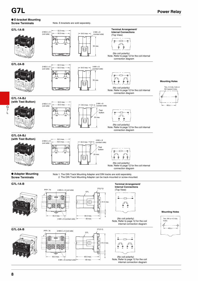
● E-bracket MountingScrew Terminals
● Adapter MountingScrew Terminals
Note. E-brackets are sold separately.
Two, 4.5-dia. hole or M4 tapped holes
52.5 max.
34.5 max.
55 max.
50.5 max.
0 1
4 6
40±0.1
2-M3.5 × 6 (coil side)
2-M4 × 8 (contact side)
52.5 max.
34.5 max.
55 max.
50.5 max.2-M3.5 × 6 (coil side)
2-M4 × 8 (contact side)
52.5 max.
34.5 max.
55 max.
50.5 max.2-M3.5 × 6 (coil side)
4-M4 × 8 (contact side)
0 1
42 6 8
0 1
4 6
0 1
42 6 8
2
Test button
52.5 max.
34.5 max.
55 max.
50.5 max.2-M3.5 × 6 (coil side)
4-M4 × 8 (contact side)2
Test button
G7L-1A-B Terminal Arrangement/Internal Connections(Top View)
Mounting Holes
G7L-2A-B
G7L-1A-BJ(with Test Button)
G7L-2A-BJ(with Test Button)
Note. Refer to page 12 for the coil internal connection diagram
(No coil polarity)
Note. Refer to page 12 for the coil internal connection diagram
(No coil polarity)
Note. Refer to page 12 for the coil internal connection diagram
(No coil polarity)
Note. Refer to page 12 for the coil internal connection diagram
(No coil polarity)
Note 1. The DIN Track Mounting Adapter and DIN tracks are sold separately.2. The DIN Track Mounting Adapter can be track-mounted or screw-mounted.
Two, M4 or 4.5-dia. holes
51.5 max.
65.5 max.55.5 max.
69 max.
51.5 max.
65.5 max.55.5 max.
69 max.
PFP-@N 2-M3.5 × 6 (coil side)
2-M4 × 8 (contact side)
2-M3.5 × 6 (coil side)
4-M4 × 8 (contact side)
G7L
P7LF-D
PFP-@NG7L
P7LF-D40±0.1
0 1
4
5
5
6
0 1
42 6 8
G7L-1A-B Terminal Arrangement/Internal Connections(Top View)
Mounting Holes
G7L-2A-B
Note. Refer to page 12 for the coil internal connection diagram
(No coil polarity)
Note. Refer to page 12 for the coil internal connection diagram
(No coil polarity)

9
G7L Power Relay
G7L
● Upper Bracket MountingScrew Terminals
Two, M4 or 4.5-dia. holes
51.5 max.
65.5 max.55.5 max.
69 max.
51.5 max.
65.5 max.55.5 max.
69 max.
PFP-@N 2-M3.5 × 6 (coil side)
2-M4 × 8 (contact side)
2-M3.5 × 6 (coil side)
4-M4 × 8 (contact side)
G7L
P7LF-D
PFP-@NG7L
P7LF-D40±0.1
0 1
4
5
2
2
5
6
0 1
42 6 8
Test button
Test button
G7L-1A-BJ(with Test Button)
Terminal Arrangement/Internal Connections(Top View)
Mounting Holes
Note. Refer to page 12 for the coil internal connection diagram
G7L-2A-BJ(with Test Button)
(No coil polarity)
Note. Refer to page 12 for the coil internal connection diagram
(No coil polarity)
Two, 4.5-dia. hole or M4 tapped holes
2.5
4.5
68.5 max.
34.5 max.
49 max. 0 1
4 6
0 1
42 6 8
50.5 max.
60
2.5
4.5
68.5 max.
34.5 max.
49 max.
50.5 max.
60
2.5
4.5
68.5 max.
34.5 max.
49 max. 0 1
4 6
0 1
42 6 8
2
2
50.5 max.
60
2.5
4.5
68.5 max.
34.5 max.
49 max.
50.5 max.
60
60±0.2
Test button
Test button
2-M3.5 × 6 (coil side)
2-M3.5 × 6 (coil side)
2-M4 × 8 (contact side)
4-M4 × 8 (contact side)
2-M3.5 × 6 (coil side) 2-M4 × 8
(contact side)
2-M3.5 × 6 (coil side) 4-M4 × 8
(contact side)
G7L-1A-BUBTerminal Arrangement/Internal Connections(Top View)
Mounting Holes
G7L-2A-BUB
G7L-1A-BUBJ(with Test Button)
G7L-2A-BUBJ(with Test Button)
Note. Refer to page 12 for the coil internal connection diagram
(No coil polarity)
Note. Refer to page 12 for the coil internal connection diagram
(No coil polarity)
Note. Refer to page 12 for the coil internal connection diagram
(No coil polarity)
Note. Refer to page 12 for the coil internal connection diagram
(No coil polarity)
10
G7L Power Relay
G7L
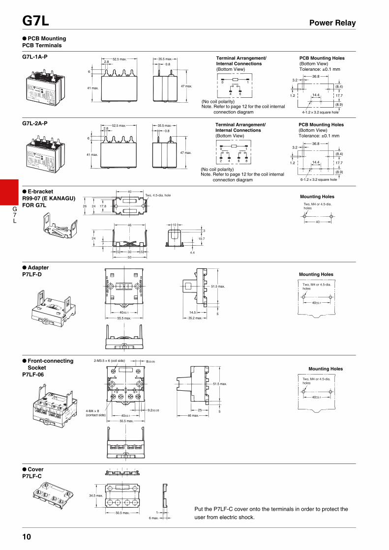
● PCB MountingPCB Terminals
36.8
14.4
3.2
1.2
4-1.2 × 3.2 square hole
17.7
6
2.80.8
52.5 max.
41 max.
35.5 max.
47 max.0 1
4 6
(8.4)
(8.9)
G7L-1A-P Terminal Arrangement/Internal Connections(Bottom View)
PCB Mounting Holes(Bottom View)Tolerance: ±0.1 mm
Note. Refer to page 12 for the coil internal connection diagram
(No coil polarity)
(8.4)
36.8
14.4
3.2
1.2
6-1.2 × 3.2 square hole
17.7
(8.9)
6
2.80.8
52.5 max.
41 max.
35.5 max.
47 max.0 1
2 4 86
G7L-2A-P Terminal Arrangement/Internal Connections(Bottom View)
PCB Mounting Holes(Bottom View)Tolerance: ±0.1 mm
Note. Refer to page 12 for the coil internal connection diagram
(No coil polarity)
Two, 4.5-dia. hole
26 24
24
17.8
40
46 10
4.4
3
19.7
30
50
5 5
7
40
Two, M4 or 4.5-dia. holes
● E-bracketR99-07 (E KANAGU)FOR G7L
Mounting Holes
14.5 5
Two, M4 or 4.5-dia. holes
55.5 max. 35.2 max.
51.5 max.
40±0.1
40±0.1
● AdapterP7LF-D Mounting Holes
40±0.1
8±0.05
9.2±0.05
55.5 max.
46 max.
51.5 max.
25 5
Two, M4 or 4.5-dia. holes
40±0.1
2-M3.5 × 6 (coil side)
4-M4 × 8 (contact side)
● Front-connecting Socket
P7LF-06Mounting Holes
34.5 max.
50.5 max.
6 max.
1
● CoverP7LF-C
Put the P7LF-C cover onto the terminals in order to protect the user from electric shock.

11
G7L Power Relay
G7L
A variety of Safety Standard approved products for standard models.UL Recognized (File No. E41643)
CSA certified (File No. LR31928)
●ReferenceUL Approved Type ....................................................
UL508 Industrial Control DevicesUL1950 Information processing equipment(Including office equipment)
CSA Approved Type ..................................................CSA C22.2 No.1, 14Industrial Control DevicesCSA C22.2 No.950 Information processing equipment(Including office equipment)
TÜV EN/IEC Standard Approved Type......................EN61810-1 RelayEN60950 Information processing equipment(Including office equipment)IEC950 Information processing equipment(Including office equipment)
EN/IEC, TÜV Certified (Certificate No. R50059083)
Approved Standards
Model Coil ratings Contact ratings Number of test operations
G7L-1A-T@G7L-1A-B@G7L-1A-PG7L-2A-T@G7L-2A-B@G7L-2A-P
12 to 240 VAC6 to 220 VDC
30 A, 277 VAC (RES) 40°C 100,0001.5 kW, 120 VAC (T) 40°C 6,0001.5 HP, 120 VAC 40°C 1,0003 HP 277 VAC 40°C 100,00020 FLA/120 LRA, 120 VAC 40°C
30,00017 FLA/102 LRA, 277 VAC 40°CTV-10, 120 VAC 40°C 25,000
Model Coil ratings Contact ratings Number of test operations
G7L-1A-P 12 to 240 VAC6 to 220 VDC
2.4 kW, 120 VAC (T) 40°C 6,0001.5 HP, 120 VAC (T) 40°C
1,0003 HP 277 VAC 40°C20.5 FLA/105 LRA, 120 VAC 85°C 100,000TV-10, 120 VAC 40°C 25,000
G7L-1A-T@G7L-1A-B@
G7L-2A-T@G7L-2A-B@G7L-2A-P
12 to 240 VAC6 to 220 VDC
30 A, 277 VAC (RES) 40°C 100,0002.4 kW, 120 VAC (T) 40°C 6,0001.5 HP, 120 VAC 40°C
1,0003 HP 277 VAC 40°C20.5 FLA/105 LRA, 120 VAC 85°C 100,000TV-10, 120 VAC 40°C 25,000
Model Coil ratings Contact ratingsApproved switching operations
G7L-1A-B@
6, 12, 24, 48, 100, 110, 200, 220 VDC12, 24, 50, 100 to 120, 200 to 240 VAC
SPST-NO (1a)
50,00030 A, 250 VAC ~ (cosφ = 1) 60°C25 A, 250 VAC ~ (cosφ = 0.4) 60°C30 A, 120 VAC ~ (cosφ = 0.4) 60°C
G7L-2A-B@DPST-NO (2a)
50,00025 A, 277 VAC ~ (cosφ = 1) 60°C25 A, 277 VAC ~ (cosφ = 0.4) 60°C
G7L-1A-T@
SPST-NO (1a)
50,00025 A, 240 VAC ~ (cosφ = 1) 60°C25 A, 240 VAC ~ (cosφ = 0.4) 60°C25 A, 277 VAC ~ (cosφ = 1) 60°C25 A, 277 VAC ~ (cosφ = 0.4) 60°C
G7L-2A-T@
DPST-NO (2a)
50,00025 A, 240 VAC ~ (cosφ = 1) 60°C25 A, 240 VAC ~ (cosφ = 0.4) 60°C25 A, 277 VAC ~ (cosφ = 1) 60°C25 A, 277 VAC ~ (cosφ = 0.4) 60°C
G7L-1A-P
SPST-NO (1a)
50,00020 A, 240 VAC ~ (cosφ = 1) 60°C20 A, 240 VAC ~ (cosφ = 0.4) 60°C25 A, 277 VAC ~ (cosφ = 1) 60°C25 A, 277 VAC ~ (cosφ = 0.4) 60°C
G7L-2A-P
DPST-NO (2a)
50,00020 A, 240 VAC ~ (cosφ = 1) 60°C20 A, 240 VAC ~ (cosφ = 0.4) 60°C25 A, 277 VAC ~ (cosφ = 1) 60°C25 A, 277 VAC ~ (cosφ = 0.4) 60°C
12
G7L Power Relay
G7L
■Precautions● Please refer to “PCB Relays Common Precautions” for general precautions.
● Installation• Although there are not specific limits
on the installation site, it should be as dry and dust-free as possible.
• Using in an atmosphere of high temperature, high humidity and corrosive gas may deteriorate its performance characteristic caused by condensation or corrosive products, resulting in failure or burn damage of the Relay.
• PCB Terminal-equipped Relays weigh approximately 100 g.Be sure that the PCB is strong enough to support them. We recommend dual-side through-hole PCBs to reduce solder cracking from heat stress.
• Relays with test buttons must be mounted facing down.Be careful not to touch the test button accidentally. Doing so may turn ON the contact.
• Be sure to use the test button for test purposes only (with test-button models). The test button is used for Relay circuit tests, such as circuit continuity tests. Do not attempt to switch the load with the test button.
● Micro Loads• The G7L is used for switching power
loads, such as motor, transformer, solenoid, lamp, and heater loads. Do not use the G7L for switching micro loads, such as signals.
● Soldering PCB Terminals• Do not perform automatic soldering
but solder manually.• Solder with the following conditions:
Soldering iron temperature (max.) 380°C, Soldering time within 10 seconds.
• Do not wash down the entire Relay because it does not have an airtight construction.
Correct Use
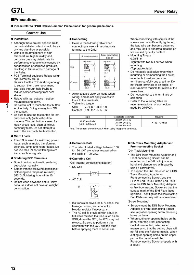
● Connecting• Refer to the following table when
connecting a wire with a crimpstyle terminal to the G7L.
• Allow suitable slack on leads when wiring, and do not apply excessive force to the terminals.
• Tightening torqueCoil: 0.78 to 1.18 N . mContact: 0.98 to 1.37 N . m
Screw terminalsFront-connecting
Socket
Coil
Contact
8
5
M3.5
5.8
8
5.3
M3.5
6.5
9.2
5.5
M4
6.5
9.2
5.5
M4
7
When connecting with screws, if the screws are not sufficiently tightened, the lead wire can become detached and may lead to abnormal heating or fire caused by faulty contact.
• Mounting Torque0.98N . mTighten with two M4 screws when mounting.(Top bracket type)
• Do not apply excessive force when mounting or dismounting the Faston receptacle.Insert and remove terminals carefully one at a time. Do not insert terminals at an angle, or insert/remove multiple terminals at the same time.
• Do not connect to the terminals by soldering
• Refer to the following table for recommendations of connectors made by OMRON.
Note. The current should be 25 A when using receptacle terminals.
Type Receptacle terminals Housing
#250 terminals (width: 6.35 mm)
XT3W-S441-12XT3W-S442-12XT3W-S443-12
XT3B-1S white
● Reference Data• The ratio of rated voltage between 100
to 120 VAC are values measured on the basis of 100 VAC.
● Operating Coil(Coil internal connections diagram)
• DC Coil
• AC Coil
• If a transistor drives the G7L check the leakage current, and connect a bleeder resistor if necessary.
• The AC coil is provided with a built-in full-wave rectifier. If a triac, such as an SSR, drives the G7L, the G7L may not release. Be sure to perform a trial operation with the G7L and the triac before applying them to actual use.
0 1
0 1
● DIN Track Mounting Adapter and Front-connecting Socket
(DIN Track Mounting)
• The DIN Track Mounting Adapter and Front-connecting Socket can be mounted on the G7L with just one hand and dismounted with ease by using a screwdriver.
• To support the G7L mounted on a DIN Track Mounting Adapter or Front-connecting Socket, use the PFP-M End Plate. Put the End Plate onto the DIN Track Mounting Adapter or Front-connecting Socket so that the surface mark of the End Plate faces upwards. Then tighten the screw of the End Plate securely with a screwdriver.
(Screw Mounting)
• Screw-mount the DIN Track Mounting Adapter or Front-connecting Socket securely after opening screw mounting holes on them.
• When cutting or opening holes on the panel after the Front-connecting Socket is mounted, take proper measures so that the cutting chips will not fall onto the Relay terminals. When cutting or opening holes on the upper part of the panel, mask the Front-connecting Socket properly with a cover.

13
G7L Power Relay
G7L
• Application examples provided in this document are for reference only. In actual applications, confirm equipment functions and safety before using the product. • Consult your OMRON representative before using the product under conditions which are not described in the manual or applying the product to nuclear control systems, railroad
systems, aviation systems, vehicles, combustion systems, medical equipment, amusement machines, safety equipment, and other systems or equipment that may have a serious influence on lives and property if used improperly. Make sure that the ratings and performance characteristics of the product provide a margin of safety for the system or equipment, and be sure to provide the system or equipment with double safety mechanisms.
Cat. No. J055-E1-141116(0207)(O)
Note: Do not use this document to operate the Unit.
OMRON CorporationElectronic and Mechanical Components Company Contact: www.omron.com/ecb