

G2 & G3 Edition - CANCAM · cancam nk105 operation manual iv 1-888-510-2295 load an eng file with...
89
G2 & G3 Edition
Transcript of G2 & G3 Edition - CANCAM · cancam nk105 operation manual iv 1-888-510-2295 load an eng file with...

TABLE OF CONTENTS
A MESSAGE FROM CANCAM 1
SAFETY INSTRUCTIONS 3BEFORE YOU BEGIN . . . . . . . . . . . . . . . . . . . . . . . . . . . . . . . 3
TRAINING & AUTHORIZATION . . . . . . . . . . . . . . . . . . . . . 3SAFETY SYMBOLS . . . . . . . . . . . . . . . . . . . . . . . . . . . . . . . 4DAMAGED PARTS . . . . . . . . . . . . . . . . . . . . . . . . . . . . . . . 5PERSONAL PROTECTIVE EQUIPMENT . . . . . . . . . . . . . . . . 5SAFETY FEATURES . . . . . . . . . . . . . . . . . . . . . . . . . . . . . . 5ELECTRICAL PANEL . . . . . . . . . . . . . . . . . . . . . . . . . . . . . . 6MODIFICATIONS . . . . . . . . . . . . . . . . . . . . . . . . . . . . . . . . 6LOCAL REGULATIONS . . . . . . . . . . . . . . . . . . . . . . . . . . . . 6
SAFE OPERATING INSTRUCTIONS . . . . . . . . . . . . . . . . . . . 7FIRE HAZARDS . . . . . . . . . . . . . . . . . . . . . . . . . . . . . . . . . 10
INTRODUCTION 11INTRODUCTION TO NK105 . . . . . . . . . . . . . . . . . . . . . . . . . 11MECHANICAL DIMENSION . . . . . . . . . . . . . . . . . . . . . . . . . 11TERMINAL SPECIFICATION OF NK105 CONTROL BOX . . . . 13INPUT INTERFACE OF +24V POWER . . . . . . . . . . . . . . . . . 16
INSTALLATION 17UNPACKING AND MACHINE IDENTIFICATION . . . . . . . . . . 17MEASURING FORKS AND FORKLIFTING MACHINE . . . . . . 18 ELECTRICAL CONNECTIONS . . . . . . . . . . . . . . . . . . . . . . . 20
ELECTRICAL SPECIFICATIONS . . . . . . . . . . . . . . . . . . . . 20ATTACH KEYBOARD . . . . . . . . . . . . . . . . . . . . . . . . . . . . 20HOUSING CABINET . . . . . . . . . . . . . . . . . . . . . . . . . . . . . 20POWER-IN CONNECTOR . . . . . . . . . . . . . . . . . . . . . . . . . 20
PNEUMATIC CONNECTIONS . . . . . . . . . . . . . . . . . . . . . . . . 21
WWW.CANCAM.CA I
CANCAM NK105 OPERATION MANUAL
AIR INPUT . . . . . . . . . . . . . . . . . . . . . . . . . . . . . . . . . . . 21VACUUM PUMP CONNECTIONS . . . . . . . . . . . . . . . . . . . . 21
BASIC CONFIGURATION OF NCSTUDIO . . . . . . . . . . . . . . . 24NCSTUDIO SYSTEM UPDATE . . . . . . . . . . . . . . . . . . . . . . . . 24
CONFIGURATION UPDATE: . . . . . . . . . . . . . . . . . . . . . . . 24SYSTEM MIRROR UPDATE: . . . . . . . . . . . . . . . . . . . . . . . 24EX-FACTORY PARAMETERS: . . . . . . . . . . . . . . . . . . . . . . 25SYSTEM APPLICATION UPDATE: . . . . . . . . . . . . . . . . . . . 25
BASIC CONCEPTS OF NK105 27OPERATION MODE AND STATE . . . . . . . . . . . . . . . . . . . . . . 27
OPERATION MODE: . . . . . . . . . . . . . . . . . . . . . . . . . . . . . 27OPERATION STATE: . . . . . . . . . . . . . . . . . . . . . . . . . . . . 28
MACHINE COORDINATE SYSTEM . . . . . . . . . . . . . . . . . . . . 28MECHANICAL COORDINATE SYSTEM (MCS): . . . . . . . . . 30WORKPIECE COORDINATE SYSTEM (WCS): . . . . . . . . . . 30
OPERATION INSTRUCTIONS 33MACHINE START-UP . . . . . . . . . . . . . . . . . . . . . . . . . . . . . . 33
POWER ON . . . . . . . . . . . . . . . . . . . . . . . . . . . . . . . . . . . 33CONTROLLER START-UP . . . . . . . . . . . . . . . . . . . . . . . . . . . 35
MECHANICAL HOMING . . . . . . . . . . . . . . . . . . . . . . . . . . 35HOMING (WITHOUT PROMPT) . . . . . . . . . . . . . . . . . . 36
G2 PANEL KEYS . . . . . . . . . . . . . . . . . . . . . . . . . . . . . . . . . 38G2 PANEL KEYS LAYOUT . . . . . . . . . . . . . . . . . . . . . . . . . 38G2 SINGLE KEY FUNCTIONS . . . . . . . . . . . . . . . . . . . . . . 39G2 KEY COMBO FUNCTIONS . . . . . . . . . . . . . . . . . . . . . . 41
G3 PANEL KEYS . . . . . . . . . . . . . . . . . . . . . . . . . . . . . . . . . 42G3 PANEL KEYS LAYOUT . . . . . . . . . . . . . . . . . . . . . . . . . 42G3 SINGLE KEY FUNCTIONS . . . . . . . . . . . . . . . . . . . . . . 43G3 KEY COMBO FUNCTIONS . . . . . . . . . . . . . . . . . . . . . . 46
CORRECT COLLETTING GUIDELINES . . . . . . . . . . . . . . . . . 48CORRECT COLLET . . . . . . . . . . . . . . . . . . . . . . . . . . . . . . 48INCORRECT COLLET . . . . . . . . . . . . . . . . . . . . . . . . . . . . 49
SECURING STOCK MATERIAL . . . . . . . . . . . . . . . . . . . . . . . 50
II 1-888-510-2295

TABLE OF CONTENTS
VACUUM HOLD DOWN . . . . . . . . . . . . . . . . . . . . . . . . . . . 50CLAMPING . . . . . . . . . . . . . . . . . . . . . . . . . . . . . . . . . . . . 51
TOOL CALIBRATION . . . . . . . . . . . . . . . . . . . . . . . . . . . . . . 52SETTING ORIGIN . . . . . . . . . . . . . . . . . . . . . . . . . . . . . . . . 54LOADING G-CODE PROGRAM . . . . . . . . . . . . . . . . . . . . . . . 55RUNNING G-CODE PROGRAM . . . . . . . . . . . . . . . . . . . . . . . 57TOOL CHANGES . . . . . . . . . . . . . . . . . . . . . . . . . . . . . . . . . 58MENU PAGE . . . . . . . . . . . . . . . . . . . . . . . . . . . . . . . . . . . . 59
SUMMARIZATION . . . . . . . . . . . . . . . . . . . . . . . . . . . . . . 59COORDINATE AXIS: . . . . . . . . . . . . . . . . . . . . . . . . . . . 59PROCESS MODE: . . . . . . . . . . . . . . . . . . . . . . . . . . . . . 60OPERATION STATE: . . . . . . . . . . . . . . . . . . . . . . . . . . . 60SPINDLE STATE: . . . . . . . . . . . . . . . . . . . . . . . . . . . . . 60TYPE OF MANUAL SPEED: . . . . . . . . . . . . . . . . . . . . . . 60MENU PAGE: . . . . . . . . . . . . . . . . . . . . . . . . . . . . . . . . 60
BROWSE LOCAL FILES/USB FILES . . . . . . . . . . . . . . . . . 61OPERATIONS . . . . . . . . . . . . . . . . . . . . . . . . . . . . . . . . . . 62OPERATOR PARAMETERS (“OPER PARAM”) . . . . . . . . . . 63
VELOCITY PARAMETERS . . . . . . . . . . . . . . . . . . . . . . . 63PROCESSING PARAMETERS . . . . . . . . . . . . . . . . . . . . . 63OFFSET PARAMETERS . . . . . . . . . . . . . . . . . . . . . . . . . 64SPINDLE PARAMETERS . . . . . . . . . . . . . . . . . . . . . . . . 64FILE PARAMETERS . . . . . . . . . . . . . . . . . . . . . . . . . . . . 65TOOL CHANGE PARAMETERS . . . . . . . . . . . . . . . . . . . . 66COMMAND IGNORING . . . . . . . . . . . . . . . . . . . . . . . . . 67
MANUAL PROCESSING . . . . . . . . . . . . . . . . . . . . . . . . . . . . 67MODE SELECTION OF MANUAL PROCESSING . . . . . . . . . 67
JOG MOTION MODE . . . . . . . . . . . . . . . . . . . . . . . . . . . 67STEPPING MOTION MODE . . . . . . . . . . . . . . . . . . . . . . 67
PARAMETER SETTING OF MANUAL PROCESSING . . . . . . 68AUTOMATIC PROCESSING . . . . . . . . . . . . . . . . . . . . . . . . . 69
LOAD FILES . . . . . . . . . . . . . . . . . . . . . . . . . . . . . . . . . . . 69LOAD AN ORDINARY FILE . . . . . . . . . . . . . . . . . . . . . . 69
WWW.CANCAM.CA III
CANCAM NK105 OPERATION MANUAL
LOAD AN ENG FILE WITH TOOL SELECTION . . . . . . . . 70ADJUSTMENT DURING AUTOMATIC PROCESSING . . . . . 71
FEED RATE OVERRIDE ADJUSTMENT . . . . . . . . . . . . . . 71SPINDLE SPEED ADJUSTMENT . . . . . . . . . . . . . . . . . . 71SUSPEND PROCESSING AND JIGGLE . . . . . . . . . . . . . . 71CONTINUE PROCESSING AFTER PAUSE . . . . . . . . . . . . 72SOFTWARE LIMIT TREATMENT . . . . . . . . . . . . . . . . . . 72HARDWARE LIMIT TREATMENT . . . . . . . . . . . . . . . . . . 72
SHUTDOWN & REBOOT . . . . . . . . . . . . . . . . . . . . . . . . . . . . 73MAINTENANCE 75
LUBRICATION . . . . . . . . . . . . . . . . . . . . . . . . . . . . . . . . . . 75RECOMMENDED LUBRICANTS . . . . . . . . . . . . . . . . . . . . . 76LUBRICATING THE X-Y RACK AND PINION . . . . . . . . . . 76LUBRICATING THE X-Y-Z RAILS . . . . . . . . . . . . . . . . . . . 77
DAILY MAINTENANCE . . . . . . . . . . . . . . . . . . . . . . . . . . . . 78REGULAR MAINTENANCE . . . . . . . . . . . . . . . . . . . . . . . . . . 79
STEP ONE: INSPECTION . . . . . . . . . . . . . . . . . . . . . . . . . 79STEP TWO: COMPREHENSIVE CLEANING . . . . . . . . . . . . 80STEP THREE: LUBRICATION . . . . . . . . . . . . . . . . . . . . . . 80
IV 1-888-510-2295

A MESSAGE FROM CANCAM
We thank you and congratulate you for choosing CANCAM quality CNC
machines. CANCAM is a Canadian owned and operated CNC machine
manufacturer. Our mis‐sion is to provide our clients with quality technology that
allows you to create, invent, and produce your products with confidence at an
affordable cost.
This manual provides installation, operation, and safety guides, as well as mainte‐
nance procedures to keep your CANCAM machine running at its best.
We suggest that everyone operating a CANCAM machine reviews this manual
carefully, including all health and safety warnings and notices, BEFORE operating
any equipment. Serious personal injury and/or property damage will result from
improper use. We also suggest that this manual is kept nearby the machine for
convenient reference.
For the digital version of this manual as well as other helpful resources, please visit
our web‐site at www.cancam.ca.
WWW.CANCAM.CA 1

CANCAM NK105 OPERATION MANUAL
2 1-888-510-2295

SAFETY INSTRUCTIONS
• READ THESE INSTRUCTIONS THOROUGHLY BEFORE
OPERATING THIS MACHINE.
• DO NOT OPERATE MACHINE IF YOU ARE UNFAMILIAR
WITH THESE SAFE OPERATING INSTRUCTIONS.
• DO NOT OPERATE MACHINE WITHOUT KNOWING WHERE
THE <E-STOP> SWITCH IS LOCATED.
SAFETY INSTRUCTIONS
IMPROPER OR UNSAFE OPERATION OF THE MACHINE WILL RESULT IN PERSONAL INJURY, INCLUDING DEATH, AND/OR
DAMAGE TO THE EQUIPMENT.
BEFORE YOU BEGIN
TRAINING & AUTHORIZATIONOnly trained and authorized personnel should work on this machine. Untrained opera-
tors present a hazard to themselves, others, and the machine. Improper operation will
void the warranty.
DANGER!
WWW.CANCAM.CA 3

CANCAM NK105 OPERATION MANUAL
SAFETY SYMBOLS
PERSONAL PROTECTIVE EQUIPMENT
Eye Protection
Ear Protection
Respiratory Protection
HandProtection
Foot Protection
Head Protection
CAUTION!
WARNING!
DANGER!
Hazard MAY cause minor to moderate injury if ignored.
Hazard COULD cause death or serious injury if ignored.
Hazard WILL cause death or serious injury if ignored.
To avoid injury to yourself and others, as well as dam-
aging equipment, follow all safety warnings. Improper
use of this machine can and will cause serious injury
up to and including death. The following symbols are
used throughout these instructions:
4 1-888-510-2295

SAFETY INSTRUCTIONS
Operating this machine with worn out or damaged parts may cause serious injury or damage to the machine.
DAMAGED PARTS
Check for damaged parts and tools BEFORE operating the machine. Any part or
tool that is damaged should be properly repaired or replaced by authorized personnel.
Do not operate the machine if any component does not appear to be functioning cor-
rectly, and immediately contact your shop supervisor.
PERSONAL PROTECTIVE EQUIPMENTUse appropriate eye and ear protective equipment while operating the machine,
including safety goggles and ear protection.
SAFETY FEATURESDo not operate the machine unless all safety features are installed and activated,
including accessible <E-STOP> switches. Never bypass, override or deactivate a
safety feature.
E-STOP SWITCH
The <E-STOP> switch is the large, circular red switch located on the control panel.
Pressing the <E-STOP> will instantly stop all motion of the machine. Additional
WARNING!
WWW.CANCAM.CA 5

CANCAM NK105 OPERATION MANUAL
switches can be installed to ensure operators have convenient access at all times
regardless of shop layout. Each operator should be aware of all <E-STOP> locations
and should ensure unobstructed access to them at all times.
ELECTRICAL PANELThe electrical panel should be closed and the key and latches on the control cabinet
should always be secured, except during installation and service.
MODIFICATIONS
DO NOT modify or alter this equipment in any way. If modifications are required,
all modifications must be handled by CANCAM. Any modification or alteration of any
CANCAM router could lead to personal injury and/or damage to the machine and will
void your warranty.
LOCAL REGULATIONSConsult your local safety codes and regulations before operating your CANCAM router.
6 1-888-510-2295

SAFETY INSTRUCTIONS
SAFE OPERATING INSTRUCTIONS
This machine is automatically controlled and may start at any time.
1.Keep fingers, hands, and all other objects away from the machine while
the power is on. Remove any adjusting keys, wrenches, and other tools
or objects before turning the machine on.
2.The spindle head can drop without notice. Personnel must avoid the
area directly under the spindle head.
3.Make sure to have proper fire extinguishing equipment on hand at all
times and be aware of this equipment’s location.
4.Only use the machine in clean, well-lit areas that are free from
flammable liquids and excessive moisture.
5.The electrical power must meet the specifications in this manual.
Attempting to run the machine from any other source can cause severe
damage and will void the warranty.
WARNING!
CAUTION!
WWW.CANCAM.CA 7

CANCAM NK105 OPERATION MANUAL
6.Keep cables and cords away from heat, oil, and sharp edges. Do not
overstretch cables or cords or run them under other objects or over
work surfaces.
7.Exercise care with machine controls and around keyboard to avoid
unintentional starting.
8.Use proper fixtures and clamps to secure work. NEVER use hands to
secure work. Improperly clamped parts machined at high speeds/feeds
may be ejected and cause personal injury and/or property damage.
Machining oversized or marginally clamped parts is not safe.
9.Do not wear loose-fitting clothing or jewelry when operating the
machine. Long hair should be protected.
10.Stay alert at all times when operating the machine.
11.Always maintain proper balance and footing when working around the
machine. Keep work area organized and free of obstructions.
12.Do not attempt to use the machine for purposes other than what is
intended. Do not attempt to exceed limits of the machine.
WARNING!
8 1-888-510-2295

SAFETY INSTRUCTIONS
13.Follow all safety instructions and processing instructions in the MSDS
for the material being processed. Do not process toxic or flammable
material. Deadly fumes can be present.
14.Maintain equipment with care. Keep cutting tools clean and sharp.
Lubricate and change accessories when necessary. Cables and cords
should be inspected regularly. Keep controls clean and dry.
15.Use proper precautions with dust collection systems to prevent
sparks and fire hazards.
16.Ensure that tools are properly aligned to avoid tool changer damage.
17.Do not attempt to operate the machine before all of the installation
instructions have been completed.
18.Disconnect power to all system components when not in use, when
changing accessories, and before servicing. Do not loosen, remove, or
adjust machine parts or cables while power is on. Never service the
machine with the power connected.
DANGER!
CAUTION!
WARNING!
WWW.CANCAM.CA 9

CANCAM NK105 OPERATION MANUAL
FIRE HAZARDS
Prevent fire hazards by using proper feeds, speeds, and tooling while operating your
CANCAM router. Setting feeds and speeds too low and/or using dull tools creates fric-
tion at the material. The friction generates heat, which can result fire being drawn
through the vacuum table or dust collector without warning. Certain materials, espe-
cially composite materials, increase the fire hazard from friction heating caused by
dull tools.
NOTE: The shop owner is responsible to make sure that everyone who is involved with installing and operating the machine is thoroughly acquainted with the installation, operation, and safety instructions provided with the machine BEFORE they perform any actual work.
The ultimate responsibility for safety rests with the shop owner and the individuals who work with the machine.
Please contact CANCAM any time safety issues need to be addressed. Safety is our top
priority, and we are always eager to hear about suggestions to improve the safety of
our machines.
You can reach us via our website, www.cancam.ca, or call us toll-free at
1-888-510-2295. We would be glad to hear from you.
STAY SAFE!
CAUTION!
10 1-888-510-2295

INTRODUCTION
INTRODUCTION TO NK105 The embedded IPC-based, independently-developed NK105 provides its user with a wide range of engraving solutions. The NK105 integrated machine consists of the host system and operation panel. The host system, also called the control box, integrates the system control card, terminal board, and additional components. The host system connects with the opera-tion panel via 15-core extension cable.
The top and bottom areas at the back of the control box are used to inlay terminals while the left side includes USB and DB15 interfaces. The DB15 interface and operation panel are con-nected at the factory. The USB interface is for external connection with USB devices (e.g., USB flash disk).
The operation panel, also called the handheld box, is similar to a handwheel in size. Con-necting to the host system via 15-core extension cable, it is concise and portable. The oper-ation panel facilitates machine tool control independently of the distribution cabinet. Its moving distance is limited only by the extension cable’s length.
MECHANICAL DIMENSION The integral thickness of the NK105 host system is 218.3mm with terminals embedded at its top and bottom.
A diagram of the NK105 control box is shown in Fig. 2-1 (unit: mm).
WWW.CANCAM.CA 11

CANCAM NK105 OPERATION MANUAL
Fig. 2-1 Diagram of NK105 control box (mm)
12 1-888-510-2295
INTRODUCTION
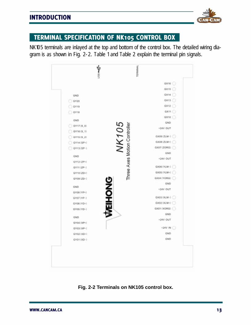
TERMINAL SPECIFICATION OF NK105 CONTROL BOX NK105 terminals are inlayed at the top and bottom of the control box. The detailed wiring dia-gram is as shown in Fig. 2-2. Table 1 and Table 2 explain the terminal pin signals.
Fig. 2-2 Terminals on NK105 control box.
WWW.CANCAM.CA 13

CANCAM NK105 OPERATION MANUAL
Table 1: Output Port Signal Explanation
Terminal
NameCorresponding Signal Note
GY01(XD-) Negative differential signal along X-axis XD+ and XD- are differential pair signals along X-axis.
GY02(XD+) Positive differential signal along X-axis
GY03(XP-) Pulse negative differential signal of X-axis XP+ and XP- are differential pair signals of X-axis pulse.
GY04(XP+) Pulse positive differential signal of X-axis
GY05(YD-) Negative differential signal along Y-axis YD+ and YD- are differential pair signals along Y-axis.
GY06(YD+) Positive differential signal along Y-axis
GY07(YP-) Pulse negative differential signal of Y-axis YP+ and YP- are pulse differ-ential pair signals of Y-axis
GY08(YP+) Pulse positive differential signal of Y-axis
GY09(ZD-) Negative differential signal along Z-axis ZD+ and ZD - are differential pair signals along Z-axis.
GY10(ZD+) Positive differential signal along Z-axis
GY11(ZP-) Pulse negative differential signal of Z-axis ZP+ and ZP- are pulse differ-ential pair signals of Z-axis.
GY12(ZP+) Pulse positive differential signal of Z-axis
GY13(SP-) Spindle reverse rotation control port
GY014(SP+) Spindle forward rotation control port
GY15(S_2) 2nd gear output port of spindle speed Multi-step spindle gear con-trol ports provide at most 8-gear speed control; in wiring, COM of spindle needs joining to GND of terminal.
GY16(S_1) 1st gear output port of spindle speed
GY17(S_0) 0th gear output port of spindle speed
GY18 Work piece cooling output port
GY19 Spindle coolant output port
GY20 Auto lubricant output port
+24V OUT +24V output It is connected with +24V power, available of use.
14 1-888-510-2295

INTRODUCTION
Table 2: Input Signal Explanation
Terminal
NameCorresponding Signal Note
GND Power GND or COM port The two GND on power terminal are connected with power GND and ground respectively, while GND on other terminals can be used as COM signal.
+24V IN +24V DC power input External connection with +24V DC power.
GX01(XORG) Mechanical origin signal of X-axis External connection with mechanical, photoelectric and proximity switch.GX02(XLM+) Positive limit signal of X-axis
GX03(XLM-) Negative limit signal of X-axis
GX04(YORG) Mechanical origin signal of Y-axis
GX05(YLM+) Positive limit signal of Y-axis
GX06(YLM-) Negative limit signal of Y-axis
GX07(ZORG) Mechanical origin signal of Z-axis
GX08(ZLM+) Positive limit signal of Z-axis
GX09(ZLM-) Negative limit signal of Z-axis
GX10 Extended input 0
GX11 Extended input 1
GX12 Extended input 2
GX13 Extended input 3
GX14 Extended input 4
GX15 E-stop alarm signal input External connection with E-stop button of machine tool.
GX16 Tool calibration input
WWW.CANCAM.CA 15

CANCAM NK105 OPERATION MANUAL
INPUT INTERFACE OF +24V POWER The input interface of +24V power is for external connection with 24V power.
Its pin definition is shown in Fig. 2-3, in which it is connected to the grounding copper plate of the machine tool.
24V+ COM
Fig. 2-3 Pin definition of +24V power input interface
16 1-888-510-2295

INSTALLATION
UNPACKING AND MACHINE IDENTIFICATION NOTE:
All CANCAM machines are shipped assembled and secured to a wooden pallet.
Unpack all items that shipped with your machine. Check the items against the packing slip to be sure nothing was left out. Notify CANCAM immediately if you are missing any piece of your shipment or if any damage has occurred during the shipping process.
Fig 3-1 Forklift tubes.
Please note the 4 forklift tubes on the front and rear of the machine (shown in Fig 3-1). There are 4 forklift tubes on the sides of the machine as well.
WWW.CANCAM.CA 17

CANCAM NK105 OPERATION MANUAL
MEASURING FORKS AND FORKLIFTING MACHINE
DO NOT OPERATE FORKLIFT WITHOUT
PROPER CERTIFICATION AND TRAINING.
The distance between the forks is 32” while the forklift tubes are 7.25” wide and 2.5” high (shown in Fig. 3-2).
Fig 3-2 Fork distance.
Centre forks in the front of the machine and move forklift slowly when close to the machine. Take care not to damage the valves on the front of the machine (shown in Fig 3-3).
WARNING!
18 1-888-510-2295

INSTALLATION
Fig 3-3 Vacuum table valves.
RAISED LOADS MAY SUDDENLY FALL WITHOUT NOTICE.
***DO NOT LIFT OR MOVE MACHINE USING GANTRY***
For safety and to prevent damage to the machine and cables, ONLY lift machine using forklift tubes.
Forklift capacity must be adequate to safely lift the load.
NOTE: We recommend forklift extensions to help support the weight of the machine.
Slowly lift up your machine from the floor, and then remove the wooden pallet without placing any body parts directly under the lifted load.
WARNING!
WWW.CANCAM.CA 19

CANCAM NK105 OPERATION MANUAL
ELECTRICAL CONNECTIONS
Ensure that all electrical connections are performed by a qualified electrician.
Improper electrical connections will result in damage to the equipment, fire, and potentially death.
ELECTRICAL SPECIFICATIONS
This CANCAM router is powered by _______________-phase 220volts. The amperage requirements for this machine are ________________.
ATTACH KEYBOARD
Once the machine has been unpacked, attach the keyboard shelf to the front of the machine. With the shelf in place, lead the mouse and keyboard cables through the small hole in the front of the machine. Plug the cables into an available USB connection on the PC.
HOUSING CABINET
All of the machine’s electronics are located in the housing cabinet. Do not open these doors when power is applied to the machine.
POWER-IN CONNECTOR
Lead the main power cable in through the hole at the bottom of the cabinet. Attach L1, L2, L3 (if applicable), and the ground wire to the connector plate (as shown in Fig. 3-4).
DANGER!
20 1-888-510-2295

INSTALLATION
Fig. 3-4 Connector plate.
PNEUMATIC CONNECTIONS Various components on the machine require air pressure. For the machine to function cor-rectly, it requires 90psi of air.
AIR INPUT
Attach an air hose to the air input on the back of the machine.
NOTE: If your shop hose does not fit the adapter supplied, the adapter can be removed and a suitable one attached.
The threading on the machine is standard 3/8 female. A male threaded 3/8 fitting to attach to your factory air hose can be purchased at most hardware stores.
VACUUM PUMP CONNECTIONS
Have a qualified electrician connect AC power (220 or 440 VAC) as specified on the unit to the motor starter.
Take the silver connector from the Starter Box and connect it to the female connector on the main electronic unit.
WWW.CANCAM.CA 21

CANCAM NK105 OPERATION MANUAL
Attach the hoses from the machine to the T-connectors and attach them to the pump.
Turn on individual sections of the vacuum table by turning the manifold handles in the front of the machine (as shown in Fig. 3-5).
Fig. 3-5 Vacuum table valves.
Vacuum on and off functions are controlled by the OSAI controller and can only be turned on from the computer screen.
To test the motor, press the reset button on the starter box once all connections are made.
22 1-888-510-2295

INSTALLATION
RUNNING THE PUMP/BLOWER CONTINUOUSLY IN THE WRONG DIRECTION WILL DAMAGE THE VANES.
Briefly start motion and check rotation (arrow on casing).
Exchange phases if rotation is incorrect.
WARNING!
WWW.CANCAM.CA 23

CANCAM NK105 OPERATION MANUAL
BASIC CONFIGURATION OF NCSTUDIO Memory: 128M
Flash: 256M
Monitor: 128 x 64 graphic LCD module
NCSTUDIO SYSTEM UPDATE The NK105 comes ready to use with all necessary software installed. To resolve some issues, the system can be updated using the following procedures:
CONFIGURATION UPDATE:
Prepare a USB flash disk (>1G) with the system image and application to be updated.
SYSTEM MIRROR UPDATE:
1. Insert the USB flash disk, with the system mirror “EBOOT 105.nb0,” “NK105.nb0,” and system application to be updated within the USB flash disk’s root directory, into the USB interface of the NK105 control box.
2. Power on NK105, and then press the “Menu” key to enter update selection interface automatically.3. Press “3” to select “OS” to start updating system image (which may take about three minutes to complete). 4. After write-in finishes, “USB Available Now!” will be displayed on the screen. Press <OK> key to enter update system interface and then select “Delete parameters.”5. After configuration files are deleted, select “Update System” to start updating the system application. After update completes, the system will reboot automatically.
24 1-888-510-2295
INSTALLATION
EX-FACTORY PARAMETERS:
Ex-factory parameters must be restored after each system update. If “Delete parameters” is not selected during the update process, it must be restored to ex-factory parameters after updating the system. Use the following procedure to restore ex-factory parameters:
1. After the system is rebooted, press to enter menu page2. Select “6. Param Upkeep,” “3. Factory Params” sequentially, and then3. Follow the on-screen prompts.
SYSTEM APPLICATION UPDATE:
A system application update is included in the system image update process. If the system image does not need updating, the system application can be updated directly using the fol-lowing procedure:
1. Insert the USB flash disk, with the system application to be updated within the USB flash disk’s root menu, into the USB interface of NK105 control box.2. Power on NK105
3. After entering the system interface, press to enter the menu page.4. Select “7. System Upkeep and “3. System Update” in turn, and then follow the on-screen prompts until “USB Available Now” appears. 5. Press “OK” key to enter update system interface, then select “Delete parameters.”6. After configuration files are deleted, select “Update system” to start updating the system application.After update completes, the system will reboot automatically.
WWW.CANCAM.CA 25

CANCAM NK105 OPERATION MANUAL
NOTE: If “Delete parameters” is not selected during the update process, it must be restored to ex-factory parameters after updating the system.
Use the above instructions to restore ex-factory parameters.
26 1-888-510-2295

BASIC CONCEPTS OF NK105
The NK105 system employs various concepts, such as the workpiece coordinate system, mechanical coordinate system, operation mode, and operation state. It is important for oper-ators to understand these concepts BEFORE operating the NK105 machine.
OPERATION MODE AND STATE
OPERATION MODE:
The machine has several operation modes, each described below.
AUTO MODE
Under automatic operation mode, the machine tool generates motions through the procedure loaded in advance. Therefore, the processing procedure must be loaded BEFORE operation in Auto Mode.
MANUAL MODE
To meet the requirements of manual motion under different situations, the system provides “jog” and “step” motion modes.
Jog motion mode: there is no concrete data control under this mode. This mode is for tuning the mechanical coordinates roughly.
Step motion mode: this motion mode is applicable to accurately tuning the mechanical coordinates of the machine.
WWW.CANCAM.CA 27
CANCAM NK105 OPERATION MANUAL
OPERATION STATE:
In terms of the motion mode of the machine tool, each operation mode can be divided into the following types of operation states:
IDLE STATE
Idle state is the most common state. Under this state, the machine has no motion to output, but is ready to accept any new task.
ESTOP STATE
This is an abnormal state. When there is an error in the hardware of the machine tool. The system will enter into this state and implement the predetermined protection actions, such as closing spindle motor and cooling pump. Under this state, the machine tool is locked and cannot carry out any new action.
RUNNING STATE
When the machine tool is implementing any action, the system enters into Running State.
PAUSE STATE
When the machine tool is running, if the user presses the combination key of “pause during processing,” the system will enter into the PAUSE State and wait for further instruction. At this time, the user can press the “Start” key to make the system enter into the RUNNING State, or press the “Stop/Cancel” key to make the system stop.
LOCK STATE
The LOCK State is an internal state occurring when software limits operation of the machine.
MACHINE COORDINATE SYSTEM The coordinate system describes the motion of the machine tool. For the sake of uniformity, the standard coordinate system adopts the right-hand rule as shown in Fig. 4-1.
28 1-888-510-2295
BASIC CONCEPTS
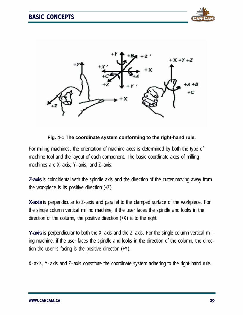
Fig. 4-1 The coordinate system conforming to the right-hand rule.
For milling machines, the orientation of machine axes is determined by both the type of machine tool and the layout of each component. The basic coordinate axes of milling machines are X-axis, Y-axis, and Z-axis:
Z-axis is coincidental with the spindle axis and the direction of the cutter moving away from the workpiece is its positive direction (+Z).
X-axis is perpendicular to Z-axis and parallel to the clamped surface of the workpiece. For the single column vertical milling machine, if the user faces the spindle and looks in the direction of the column, the positive direction (+X) is to the right.
Y-axis is perpendicular to both the X-axis and the Z-axis. For the single column vertical mill-ing machine, if the user faces the spindle and looks in the direction of the column, the direc-tion the user is facing is the positive direction (+Y).
X-axis, Y-axis and Z-axis constitute the coordinate system adhering to the right-hand rule.
WWW.CANCAM.CA 29
CANCAM NK105 OPERATION MANUAL
MECHANICAL COORDINATE SYSTEM (MCS):
Mechanical coordinate system (MCS) is a set of the fixed right-hand coordinate system. Its coordinate origin is a fixed position that corresponds to the machine tool. Therefore, at any time, any given point in space can be exclusively described by MCS.
The MCS requires that the machine is able to “home” back to the mechanical origin, or the machine will be unable to execute the software commands.
WORKPIECE COORDINATE SYSTEM (WCS):
As a set of the right-hand coordinate system, the workpiece coordinate system (WCS) is used in programming to describe motion relative to the origin (also called program origin, offset, or home). To establish WCS, the operator must identify a given point on the workpiece as the origin. The origin of WCS is fixed relative to a certain point on the workpiece, so the machine can translate the relative commands of the program to the fixed origin of MCS.
The operator can identify multiple workpiece origins, or offsets, for various subroutines. Work piece offsets correspond to the coordinate systems G54, G55, G56, G57, G58, and G59. The default coordinate system is G54.
The origin of WCS should be selected with consideration for simplified programming and dimension conversion, as well as avoiding machining errors.
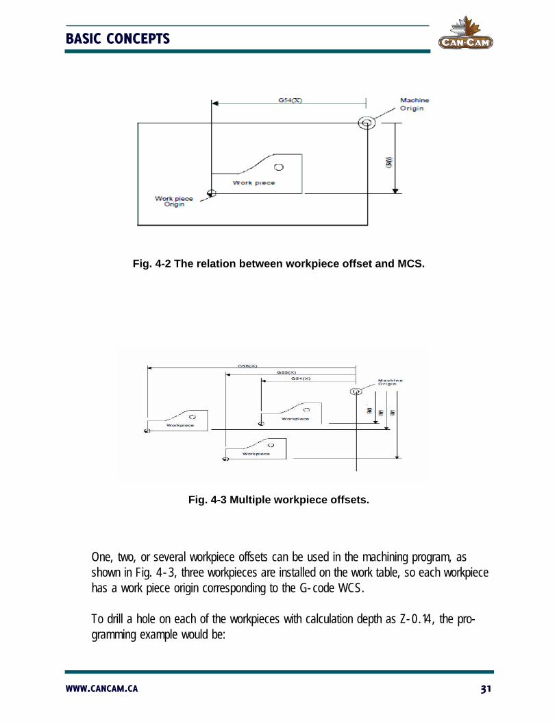
The relation between workpiece offset and MCS is shown in Fig. 4-2.
30 1-888-510-2295
BASIC CONCEPTS
Fig. 4-2 The relation between workpiece offset and MCS.
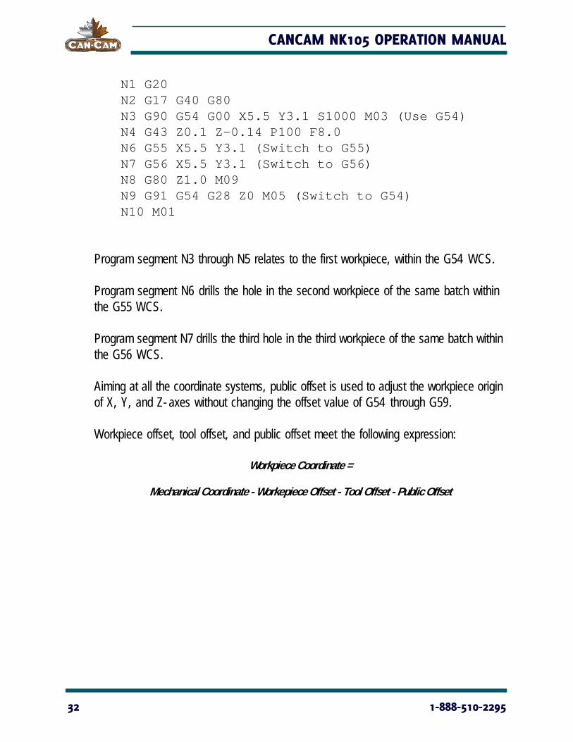
Fig. 4-3 Multiple workpiece offsets.
One, two, or several workpiece offsets can be used in the machining program, as shown in Fig. 4-3, three workpieces are installed on the work table, so each workpiece has a work piece origin corresponding to the G-code WCS.
To drill a hole on each of the workpieces with calculation depth as Z-0.14, the pro-gramming example would be:
WWW.CANCAM.CA 31
CANCAM NK105 OPERATION MANUAL
N1 G20N2 G17 G40 G80N3 G90 G54 G00 X5.5 Y3.1 S1000 M03 (Use G54)N4 G43 Z0.1 Z-0.14 P100 F8.0N6 G55 X5.5 Y3.1 (Switch to G55)N7 G56 X5.5 Y3.1 (Switch to G56)N8 G80 Z1.0 M09N9 G91 G54 G28 Z0 M05 (Switch to G54)N10 M01
Program segment N3 through N5 relates to the first workpiece, within the G54 WCS.
Program segment N6 drills the hole in the second workpiece of the same batch within the G55 WCS.
Program segment N7 drills the third hole in the third workpiece of the same batch within the G56 WCS.
Aiming at all the coordinate systems, public offset is used to adjust the workpiece origin of X, Y, and Z-axes without changing the offset value of G54 through G59.
Workpiece offset, tool offset, and public offset meet the following expression:
Workpiece Coordinate =
Mechanical Coordinate - Workepiece Offset - Tool Offset - Public Offset
32 1-888-510-2295
OPERATION INSTRUCTIONS
MACHINE START-UP
POWER ON
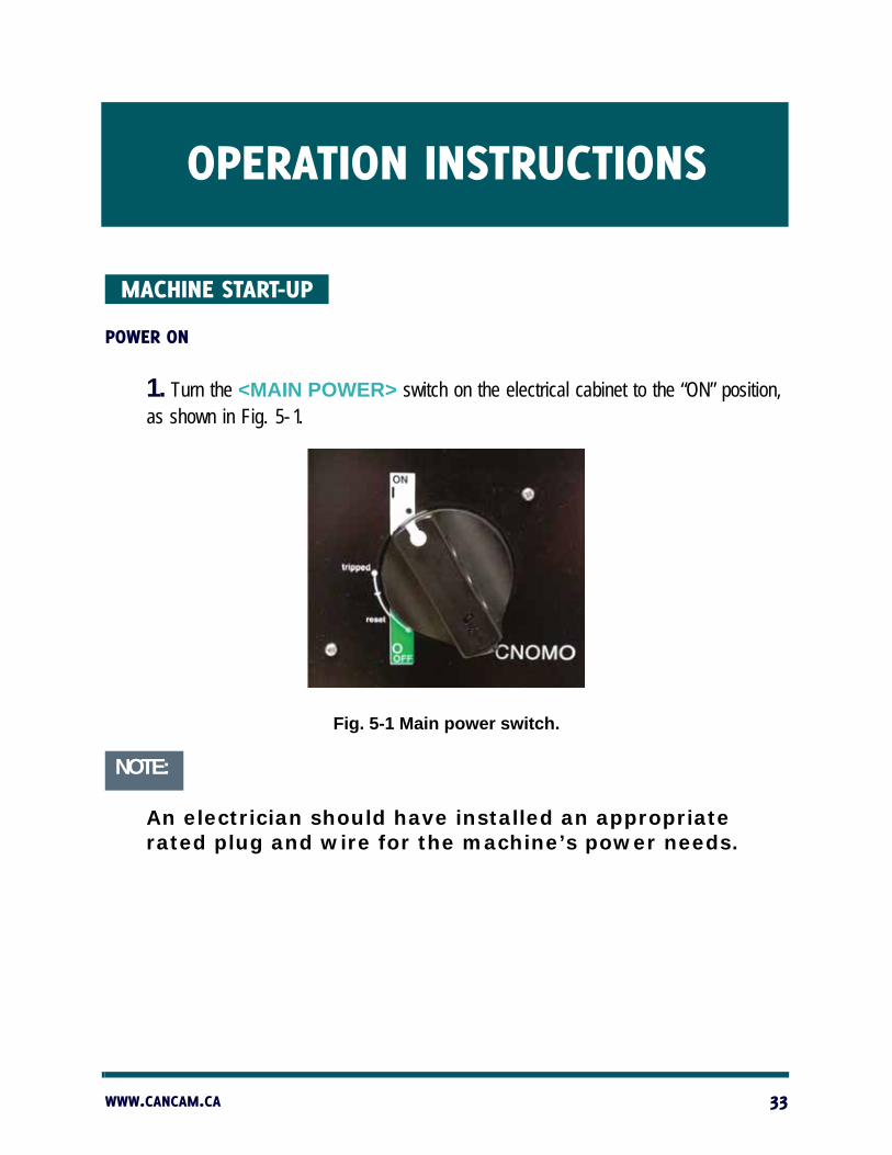
1. Turn the <MAIN POWER> switch on the electrical cabinet to the “ON” position, as shown in Fig. 5-1.
Fig. 5-1 Main power switch.
NOTE:
An electrician should have installed an appropriate rated plug and wire for the machine’s power needs.
WWW.CANCAM.CA 33

CANCAM NK105 OPERATION MANUAL
The red light on the front of the machine will light up (as shown in Fig. 5-2). This indicates that the power is available to the machine.
Fig. 5-2 Power is available.
2. Press the green <POWER ON> button to send power to the cabinet and machine. The green light (as shown in Fig. 5-3) indicates that the cabinet and machine are receiving power. The machine and controller should be booting up.
Fig. 5-3 Cabinet and machine receiving power.
NOTE:
Machine and controller will not boot if any <E-STOP> switch is activated. Some machines have additional safety features that prevent start-up, such as light curtains and door sensors. Check that all <E-STOP> switches are released and all other safety features are in operational mode.
34 1-888-510-2295
OPERATION INSTRUCTIONS
CONTROLLER START-UP
MECHANICAL HOMING
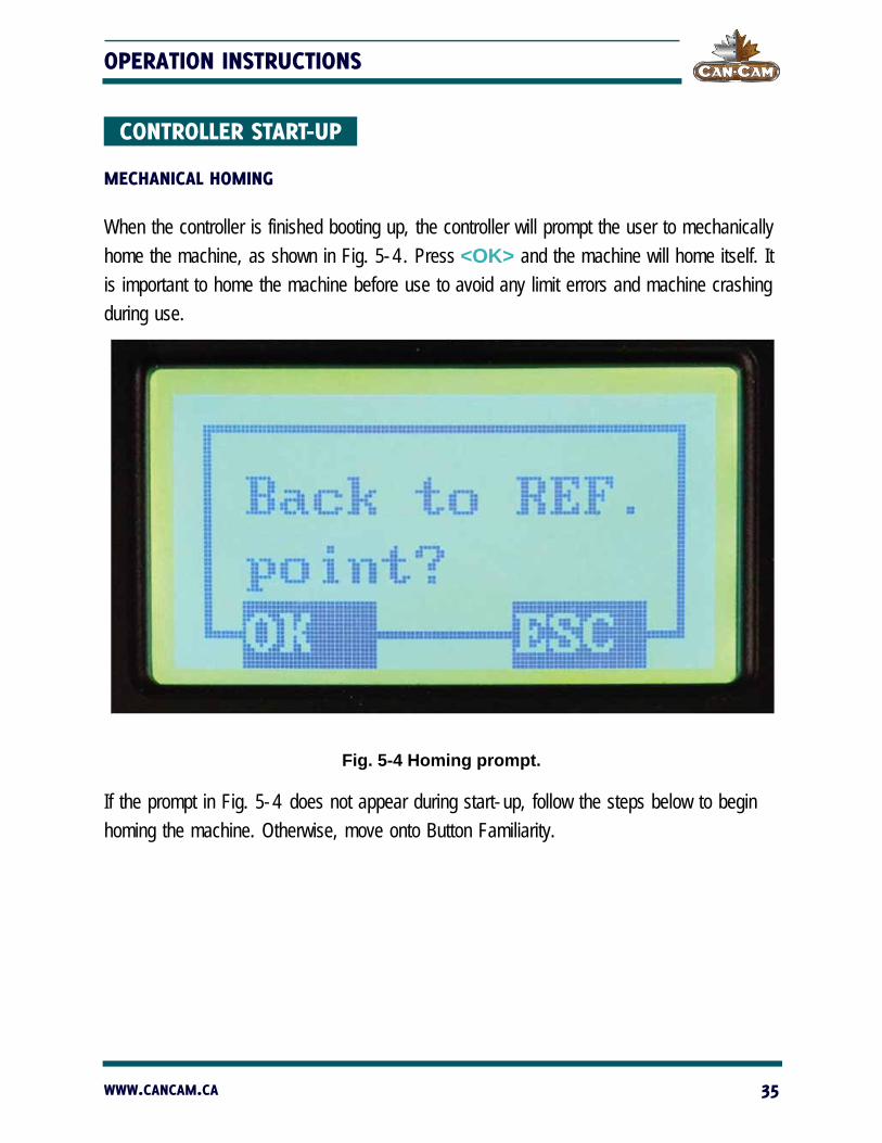
When the controller is finished booting up, the controller will prompt the user to mechanically home the machine, as shown in Fig. 5-4. Press <OK> and the machine will home itself. It is important to home the machine before use to avoid any limit errors and machine crashing during use.
Fig. 5-4 Homing prompt.
If the prompt in Fig. 5-4 does not appear during start-up, follow the steps below to begin homing the machine. Otherwise, move onto Button Familiarity.
WWW.CANCAM.CA 35
CANCAM NK105 OPERATION MANUAL
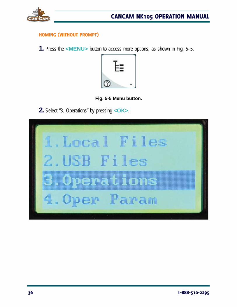
HOMING (WITHOUT PROMPT)
1. Press the <MENU> button to access more options, as shown in Fig. 5-5.
Fig. 5-5 Menu button.
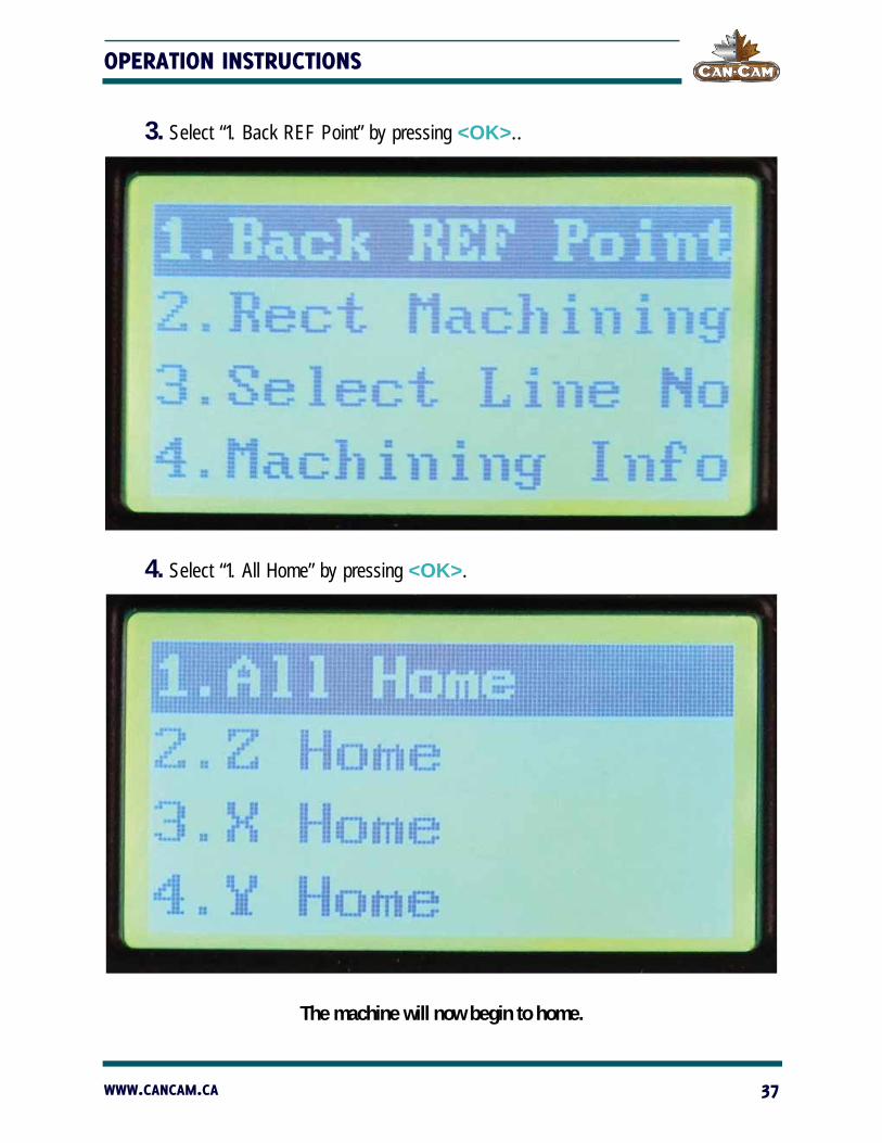
2. Select “3. Operations” by pressing <OK>.
36 1-888-510-2295
OPERATION INSTRUCTIONS
3. Select “1. Back REF Point” by pressing <OK>..
4. Select “1. All Home” by pressing <OK>.
The machine will now begin to home.
WWW.CANCAM.CA 37
CANCAM NK105 OPERATION MANUAL
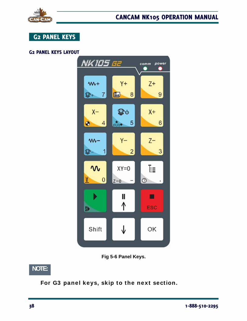
G2 PANEL KEYS
G2 PANEL KEYS LAYOUT
Fig 5-6 Panel Keys.
NOTE:
For G3 panel keys, skip to the next section.
38 1-888-510-2295
OPERATION INSTRUCTIONS
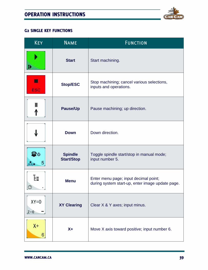
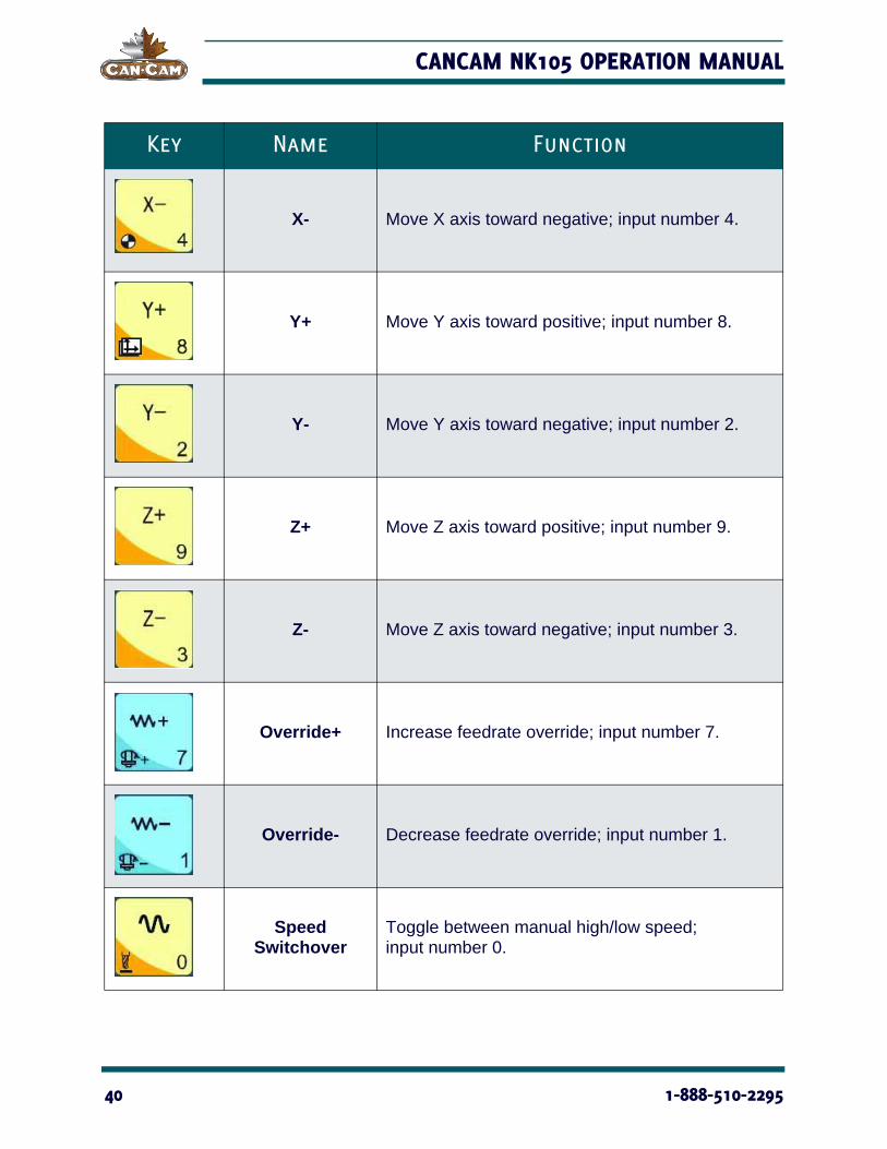
G2 SINGLE KEY FUNCTIONS
Key Name Function
Start Start machining.
Stop/ESCStop machining; cancel various selections, inputs and operations.
Pause/Up Pause machining; up direction.
Down Down direction.
Spindle Start/Stop
Toggle spindle start/stop in manual mode; input number 5.
MenuEnter menu page; input decimal point; during system start-up, enter image update page.
XY Clearing Clear X & Y axes; input minus.
X+ Move X axis toward positive; input number 6.
WWW.CANCAM.CA 39
CANCAM NK105 OPERATION MANUAL
X- Move X axis toward negative; input number 4.
Y+ Move Y axis toward positive; input number 8.
Y- Move Y axis toward negative; input number 2.
Z+ Move Z axis toward positive; input number 9.
Z- Move Z axis toward negative; input number 3.
Override+ Increase feedrate override; input number 7.
Override- Decrease feedrate override; input number 1.
Speed Switchover
Toggle between manual high/low speed; input number 0.
Key Name Function
40 1-888-510-2295
OPERATION INSTRUCTIONS
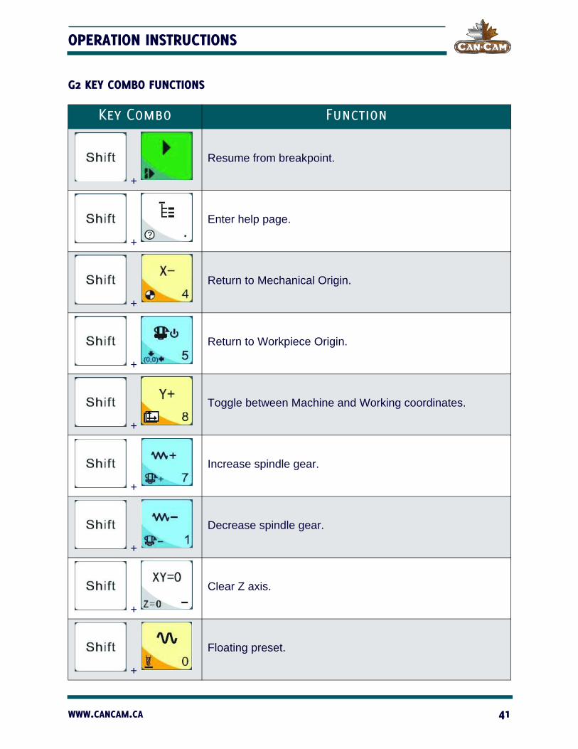
G2 KEY COMBO FUNCTIONS
Key Combo Function
+
Resume from breakpoint.
+
Enter help page.
+
Return to Mechanical Origin.
+
Return to Workpiece Origin.
+
Toggle between Machine and Working coordinates.
+
Increase spindle gear.
+
Decrease spindle gear.
+
Clear Z axis.
+
Floating preset.
WWW.CANCAM.CA 41

CANCAM NK105 OPERATION MANUAL
G3 PANEL KEYS
G3 PANEL KEYS LAYOUT
Fig 5-7 G3 Panel Keys.
42 1-888-510-2295

OPERATION INSTRUCTIONS
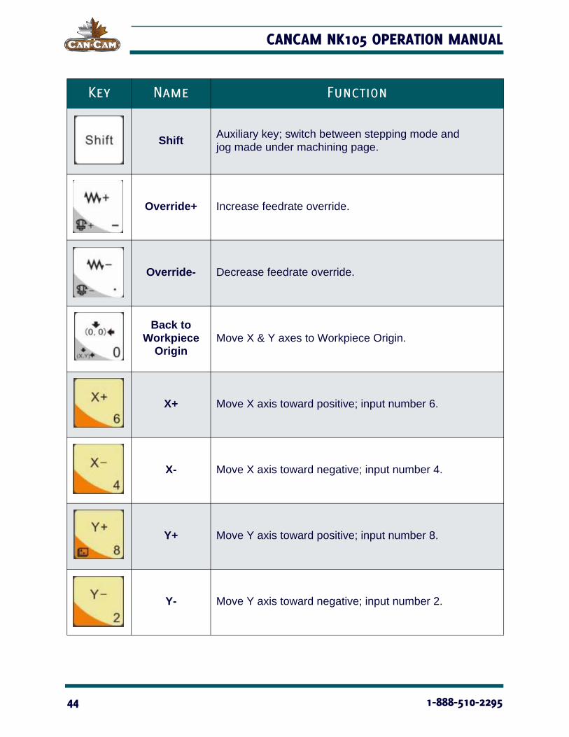
G3 SINGLE KEY FUNCTIONS
Key Name Function
Start Start machining.
Pause Pause machining.
Stop Stop machining.
Spindle ON/OFF
Toggle spindle ON/OFF in manual mode.
MenuEnter menu page; during system start-up, enter image update.
ESC Returning to the previous page.
XY Clearing Clear X & Y coordinates.
Z Clearing Clear Z coordinate.
WWW.CANCAM.CA 43
CANCAM NK105 OPERATION MANUAL
ShiftAuxiliary key; switch between stepping mode and jog made under machining page.
Override+ Increase feedrate override.
Override- Decrease feedrate override.
Back to Workpiece
OriginMove X & Y axes to Workpiece Origin.
X+ Move X axis toward positive; input number 6.
X- Move X axis toward negative; input number 4.
Y+ Move Y axis toward positive; input number 8.
Y- Move Y axis toward negative; input number 2.
Key Name Function
44 1-888-510-2295

OPERATION INSTRUCTIONS
Z+ Move Z axis toward positive; input number 9.
Z- Move Z axis toward negative; input number 3.
Speed Switchover
Toggle between jog speed and rapid jog speed in jog mode; input number 5.
IV+ Move extended axis toward positive; input number 7.
IV- Move extended axis toward negative; input number 1.
Key Name Function
WWW.CANCAM.CA 45

CANCAM NK105 OPERATION MANUAL
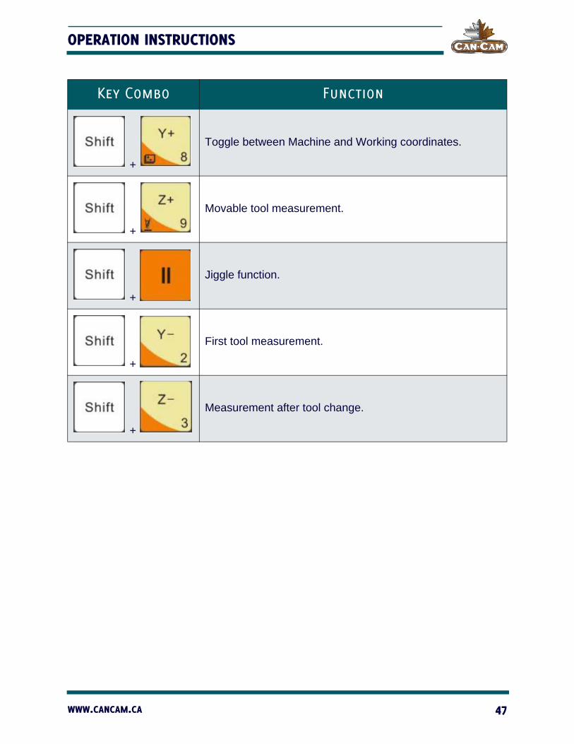
G3 KEY COMBO FUNCTIONS
Key Combo Function
+
Resume from breakpoint.
+
Open help page.
+
Clear X axis.
+
Clear Y axis.
+
Increase spindle gear.
+
Decrease spindle gear.
+
Move X & Y axes back to fixed point.
+
Home all axes.
46 1-888-510-2295
OPERATION INSTRUCTIONS
+
Toggle between Machine and Working coordinates.
+
Movable tool measurement.
+
Jiggle function.
+
First tool measurement.
+
Measurement after tool change.
Key Combo Function
WWW.CANCAM.CA 47

CANCAM NK105 OPERATION MANUAL
CORRECT COLLETTING GUIDELINES
Read these instructions thoroughly BEFORE operating machine.
UNBALANCED EQUIPMENT WILL DAMAGE SPINDLE. AIR SUPPLY MUST BE FILTERED AND DRY.
CORRECT COLLET
The end of the collet should be flush with the bottom surface of the collet nut (as shown in Fig. 5-8). You will hear and feel a “SNAP” as the collet properly moves into place within the collet nut. Once assembled, “SCREW” the collet nut onto the threaded spindle end.
Fig. 5-8 Correct collet.
CAUTION!
48 1-888-510-2295

OPERATION INSTRUCTIONS
INCORRECT COLLET
Any gap or angle between the collet and the collet nut indicates that the assembly is incorrect (as shown in Fig. 5-9). If the collet is not flush to the end of the collet nut, correct the assembly before using.
Fig. 5-9 Incorrect collet.
DO NOT PUSH THE COLLET INTO THE SPINDLE AT ANY TIME! Only insert the proper assembly onto the spindle.
NOTE:
FOR TOOLCHANGE AND FIXED COLLET SPIN-DLES:ONLY USE TOOLHOLDERS, COLLET NUTS AND TOOLS THAT ARE BALANCED TO MEET OR EXCEED THE MAX RATED SPEED OF THE SPINDLE.
CAUTION!
WWW.CANCAM.CA 49

CANCAM NK105 OPERATION MANUAL
SECURING STOCK MATERIAL All stock material must be well secured in place before operating the machine. Loose material will cause inaccuracies and may result in projectiles that cause damage to the machine and serious injury, including death.
UNSECURED WORK WILL CAUSE DAMAGE TO THE MACHINE
AND SERIOUS PERSONAL INJURY
***NEVER SECURE WORK BY HAND***
There are many methods for securing stock material. Two common methods include clamping or vacuum hold down.
VACUUM HOLD DOWN
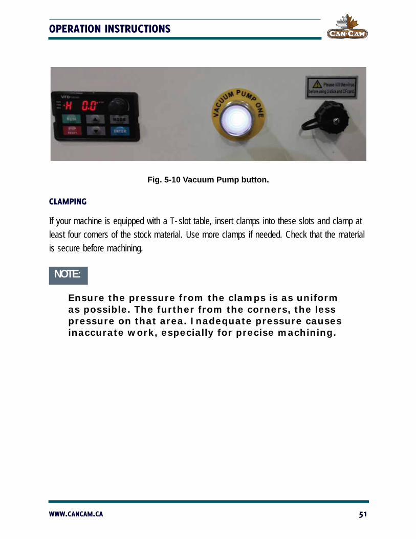
If your machine is equipped with a vacuum table, simply lay stock material on top of the spoil board and align it properly. To activate the vacuum, press the <VACUUM PUMP> button located on the electrical cabinet (as shown in Fig. 5-10). Check that the material is secure before machining.
DANGER!
50 1-888-510-2295
OPERATION INSTRUCTIONS
Fig. 5-10 Vacuum Pump button.
CLAMPING
If your machine is equipped with a T-slot table, insert clamps into these slots and clamp at least four corners of the stock material. Use more clamps if needed. Check that the material is secure before machining.
NOTE:
Ensure the pressure from the clamps is as uniform as possible. The further from the corners, the less pressure on that area. Inadequate pressure causes inaccurate work, especially for precise machining.
WWW.CANCAM.CA 51

CANCAM NK105 OPERATION MANUAL
TOOL CALIBRATION Once the material is secured, the tool can be calibrated. The calibrator is shown in Fig. 5-11 and should be placed on top of the stock material or on the spoil board if your stock material thickness has been accounted for while creating your tool path. Then jog the tool over to the calibrator and position it roughly 2-3” above the calibrator.
Fig. 5-11 Calibrator.
To activate the calibration process, the secondary function of the <SPEED> button must be used. To access this, press the <SPEED SWITCHOVER> button while holding the <SHIFT> button to activate <TOOL MEASUREMENT>.
These buttons are highlighted in Fig. 5-12.
52 1-888-510-2295
OPERATION INSTRUCTIONS
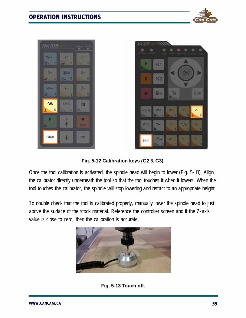
Fig. 5-12 Calibration keys (G2 & G3).
Once the tool calibration is activated, the spindle head will begin to lower (Fig. 5-13). Align the calibrator directly underneath the tool so that the tool touches it when it lowers. When the tool touches the calibrator, the spindle will stop lowering and retract to an appropriate height.
To double check that the tool is calibrated properly, manually lower the spindle head to just above the surface of the stock material. Reference the controller screen and if the Z-axis value is close to zero, then the calibration is accurate.
Fig. 5-13 Touch off.
WWW.CANCAM.CA 53
CANCAM NK105 OPERATION MANUAL
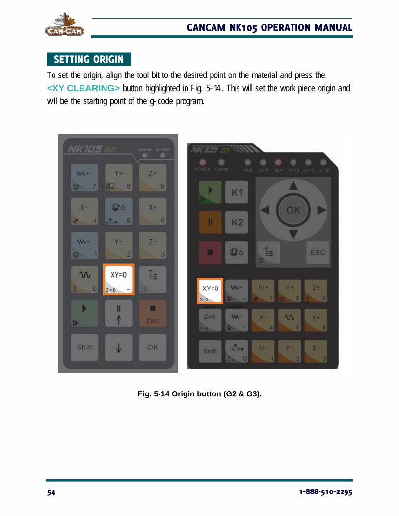
SETTING ORIGIN To set the origin, align the tool bit to the desired point on the material and press the <XY CLEARING> button highlighted in Fig. 5-14. This will set the work piece origin and will be the starting point of the g-code program.
Fig. 5-14 Origin button (G2 & G3).
54 1-888-510-2295
OPERATION INSTRUCTIONS
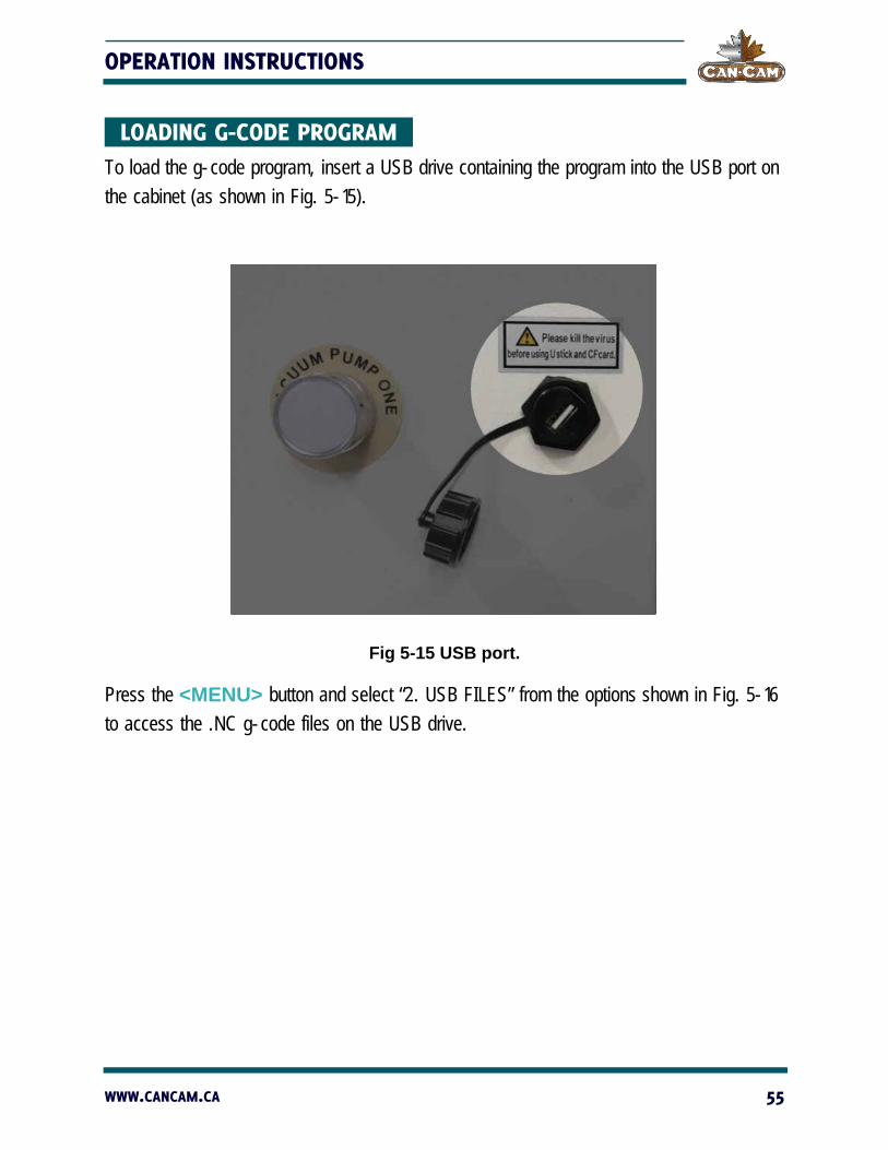
LOADING G-CODE PROGRAM To load the g-code program, insert a USB drive containing the program into the USB port on the cabinet (as shown in Fig. 5-15).
Fig 5-15 USB port.
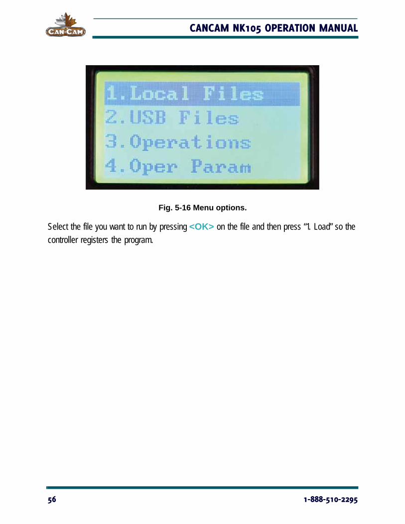
Press the <MENU> button and select “2. USB FILES” from the options shown in Fig. 5-16 to access the .NC g-code files on the USB drive.
WWW.CANCAM.CA 55
CANCAM NK105 OPERATION MANUAL
Fig. 5-16 Menu options.
Select the file you want to run by pressing <OK> on the file and then press “1. Load” so the controller registers the program.
56 1-888-510-2295
OPERATION INSTRUCTIONS
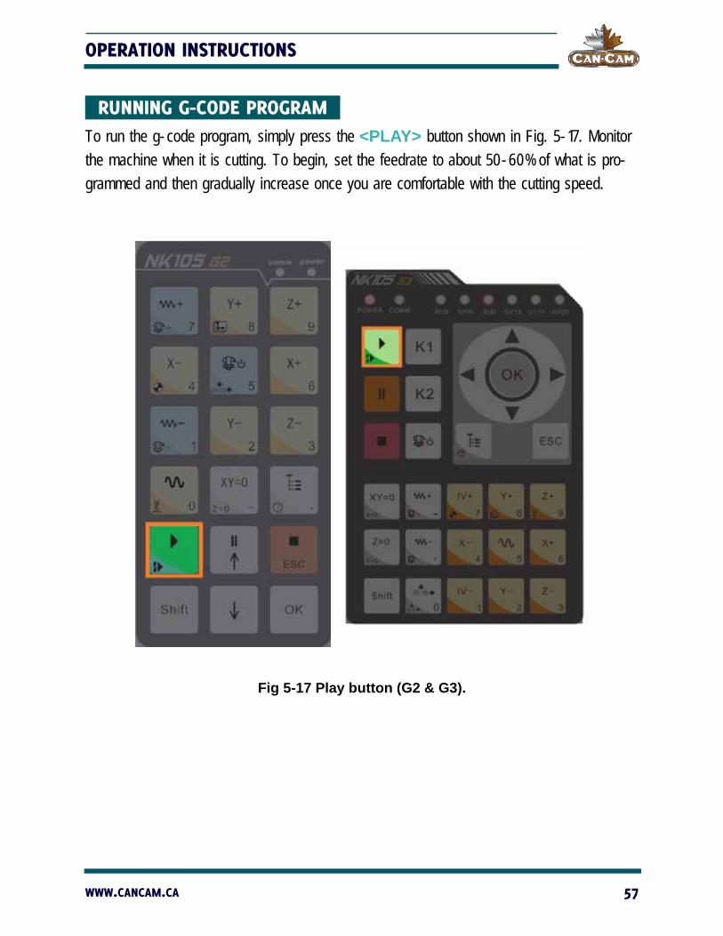
RUNNING G-CODE PROGRAM To run the g-code program, simply press the <PLAY> button shown in Fig. 5-17. Monitor the machine when it is cutting. To begin, set the feedrate to about 50-60% of what is pro-grammed and then gradually increase once you are comfortable with the cutting speed.
Fig 5-17 Play button (G2 & G3).
WWW.CANCAM.CA 57
CANCAM NK105 OPERATION MANUAL
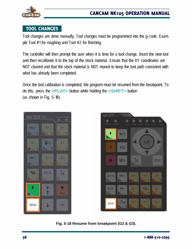
TOOL CHANGES Tool changes are done manually. Tool changes must be programmed into the g-code. Exam-ple Tool #1 for roughing and Tool #2 for finishing.
The controller will then prompt the user when it is time for a tool change. Insert the new tool and then recalibrate it to the top of the stock material. Ensure that the XY coordinates are NOT cleared and that the stock material is NOT moved to keep the tool path consistent with what has already been completed.
Once the tool calibration is completed, the program must be resumed from the breakpoint. To do this, press the <PLAY> button while holding the <SHIFT> button (as shown in Fig. 5-18).
Fig. 5-18 Resume from breakpoint (G2 & G3).
58 1-888-510-2295
OPERATION INSTRUCTIONS
MENU PAGE
SUMMARIZATION
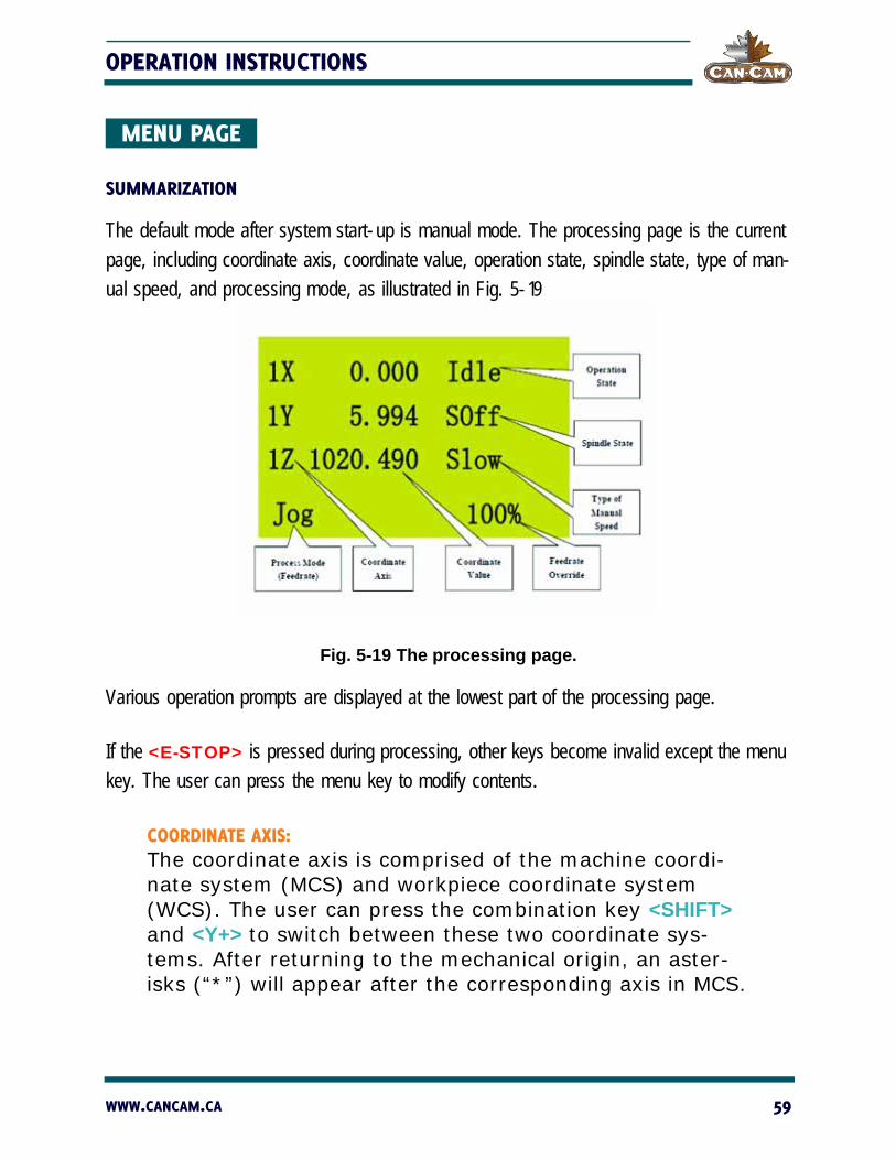
The default mode after system start-up is manual mode. The processing page is the current page, including coordinate axis, coordinate value, operation state, spindle state, type of man-ual speed, and processing mode, as illustrated in Fig. 5-19
Fig. 5-19 The processing page.
Various operation prompts are displayed at the lowest part of the processing page.
If the <E-STOP> is pressed during processing, other keys become invalid except the menu key. The user can press the menu key to modify contents.
COORDINATE AXIS:The coordinate axis is comprised of the machine coordi-nate system (MCS) and workpiece coordinate system (WCS). The user can press the combination key <SHIFT> and <Y+> to switch between these two coordinate sys-tems. After returning to the mechanical origin, an aster-isks (“*”) will appear after the corresponding axis in MCS.
WWW.CANCAM.CA 59

CANCAM NK105 OPERATION MANUAL
PROCESS MODE: Process mode includes jog and stepping modes, which can be switched by pressing <SHIFT KEY>.
OPERATION STATE:Operation state includes idle, e-stop, running, pause, and lock states.
SPINDLE STATE:Spindle state includes spindle gears and spindle stop, which can be switched by <SPINDLE START/STOP> under idle state. During processing, press
<SHIFT> + <OVERRIDE +> or <SHIFT> + <OVERRIDE ->
to increase or decrease the spindle gear. 1S represents rotate speed of the first gear, with nS representing the rotate speed of the nth gear.
TYPE OF MANUAL SPEED:Manual speed can be divided into two types: manual high speed and manual low speed, which can be selected by pressing <SPEED SWITCHOVER>.
MENU PAGE:Press <MENU> to enter the menu page. Altogether, there are eight parameter items in the menu, but the LCD can only show four of them at a time, as shown in Fig. 5-20.
Fig. 5-20 Menu items.
60 1-888-510-2295

OPERATION INSTRUCTIONS
On the menu page, press <UP> or <DOWN> to select the desired item and then press <OK> to enter the corresponding sub-menu.
BROWSE LOCAL FILES/USB FILES
The file browsing interface is shown in Fig. 5-21, in which the user can load, delete or copy a file. Only one file can be loaded to the system at a time. If several files are selected at the same time, a prompt dialog will appear.
NOTE: after <Z-> is pressed to select “(3) Copy,” a dialog box will pop up. Press <OK> to start copying. When the file is large, the system interface will display “Copying...”. Please do not press any key on the operation panel at this time and wait patiently.
Fig. 5-21 File browsing example.
WWW.CANCAM.CA 61
CANCAM NK105 OPERATION MANUAL
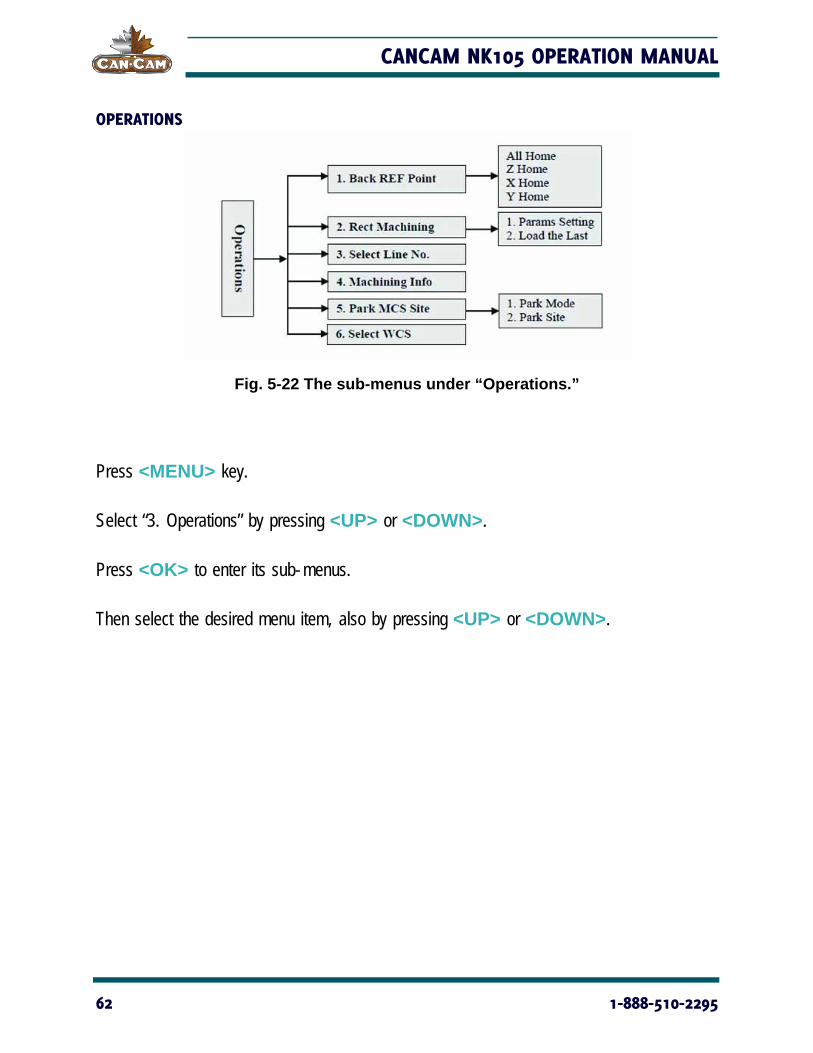
OPERATIONS
Fig. 5-22 The sub-menus under “Operations.”
Press <MENU> key.
Select “3. Operations” by pressing <UP> or <DOWN>.
Press <OK> to enter its sub-menus.
Then select the desired menu item, also by pressing <UP> or <DOWN>.
62 1-888-510-2295
OPERATION INSTRUCTIONS
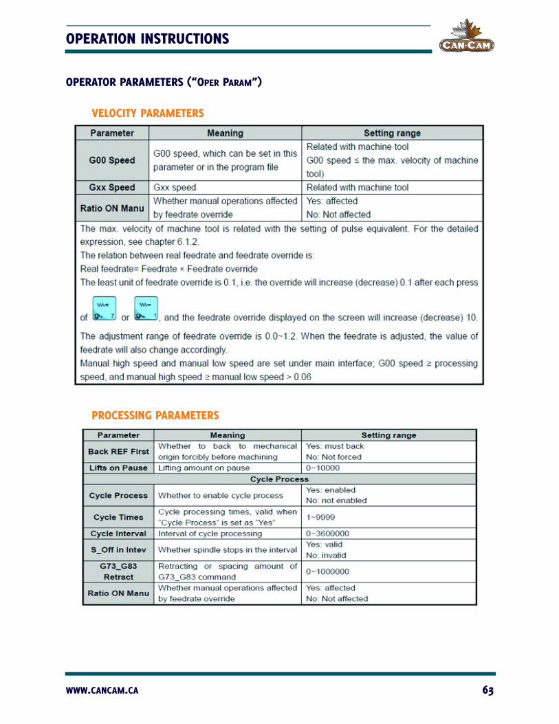
OPERATOR PARAMETERS (“OPER PARAM”)
VELOCITY PARAMETERS
PROCESSING PARAMETERS
WWW.CANCAM.CA 63

CANCAM NK105 OPERATION MANUAL
OFFSET PARAMETERS
SPINDLE PARAMETERS
64 1-888-510-2295
OPERATION INSTRUCTIONS
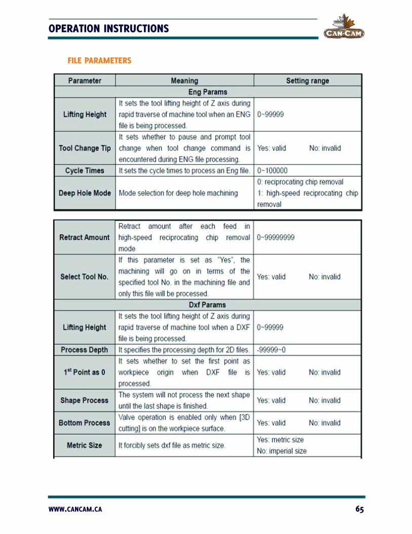
FILE PARAMETERS
WWW.CANCAM.CA 65

CANCAM NK105 OPERATION MANUAL
These two groups of parameters are specially aiming at ENG files and DXF files. The system treats each tool lifting as a process step. if several shapes, with each shape including several steps, are to be machined, the second step will not be machined until the first step of all the shapes are finished under the condition of the parameter “Shape Process” set as “No.” If the parameter “1st Point as 0” is set as “no,” the zero coordinate of DXF file will be regarded as the work piece origin in processing; if “Yes,” the self-defined point in the DXF file will be treated as workpiece origin.
For instance, when drawing a picture with CAD, the user can define a point (this point will not be processed) freely in the picture (it’s better if the point is near or within the picture); and then the system will treat it as a workpiece origin. If there are several points in the DXF, the system will assume the first drawn point is a workpiece origin.
TOOL CHANGE PARAMETERS
66 1-888-510-2295
OPERATION INSTRUCTIONS
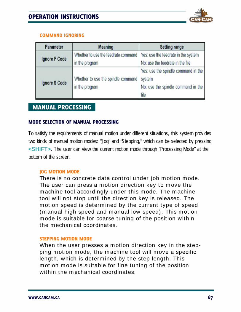
COMMAND IGNORING
MANUAL PROCESSING
MODE SELECTION OF MANUAL PROCESSING
To satisfy the requirements of manual motion under different situations, this system provides two kinds of manual motion modes: “Jog” and “Stepping,” which can be selected by pressing <SHIFT>. The user can view the current motion mode through “Processing Mode” at the bottom of the screen.
JOG MOTION MODEThere is no concrete data control under job motion mode. The user can press a motion direction key to move the machine tool accordingly under this mode. The machine tool will not stop until the direction key is released. The motion speed is determined by the current type of speed (manual high speed and manual low speed). This motion mode is suitable for coarse tuning of the position within the mechanical coordinates.
STEPPING MOTION MODEWhen the user presses a motion direction key in the step-ping motion mode, the machine tool will move a specific length, which is determined by the step length. This motion mode is suitable for fine tuning of the position within the mechanical coordinates.
WWW.CANCAM.CA 67

CANCAM NK105 OPERATION MANUAL
PARAMETER SETTING OF MANUAL PROCESSING
Basic parameters of manual processing include: manual high speed (i.e. “High shown in the processing page), manual low speed (i.e., “Slow” shown in the processing page), X\Y step and Z step.
Under the main interface, press <OK> to enter the parameter setting interface of manual processing, as shown in Fig. 5-23.
Fig. 5-23 Parameter setting interface of manual processing.
68 1-888-510-2295

OPERATION INSTRUCTIONS
Press <UP> or <DOWN> to select the desired parameter and then press <OK> to con-firm. Note that modifications should be within the parameter range. The current file name is displayed at the bottom line. Press <UP> or <DOWN> to move the cursor to this line, and then press <OK> to enter the file list of C: disk, as shown in Fig. 5-24. Within this interface, the user can only load files, not delete or copy them.
Fig. 5-24 Load file prompt.
If there is no file in C: disk, the prompt “File Not Found, Show USB File?” will appear; press <OK> to enter the file list of the USB flash disk.
To switch between USB file list and C: file list, press <SPEED SWITCHOVER>.
AUTOMATIC PROCESSING Automatic processing refers to the system processing system files and the files in the USB flash disk in terms of instructions (also called file processing). All the parameters of the machine tool and system should be set correctly before automatic processing starts.
LOAD FILES
LOAD AN ORDINARY FILEPress <MENU> to enter the menu page. Press <UP> and <DOWN> to select “Local Files” or “USB Files.”Press <OK> to enter the corresponding file list interface. Press <OK> to select the processing file to be machines. Press <OVERRIDE -> to load the selected file.
WWW.CANCAM.CA 69

CANCAM NK105 OPERATION MANUAL
LOAD AN ENG FILE WITH TOOL SELECTION FUNCTIONEnter the file list according to the method for loading an ordinary file, and then press <OK> to select ENG file to be machined. Press <OVERRIDE -> to enter tool selection interface automatically as shown in Fig. 5-25.
Fig. 5-25 Tool selection interface.
Number of tools: the number of tools in this ENG file.
Tool No.: the current tool No., select with <UP> and <DOWN>.
Cutter: selected by pressing the <UP> and <DOWN>, displaying tool sequence number and name.
After the parameters are set, press <OK> to load the file. After loading, the system will return to the processing page automatically.
70 1-888-510-2295

OPERATION INSTRUCTIONS
ADJUSTMENT DURING AUTOMATIC PROCESSING
FEED RATE OVERRIDE ADJUSTMENTFeed rate override can be adjusted by pressing either <OVERRIDE +> or <OVERRIDE -> during file processing. The feed rate changes with the feed rate override. The relation between actual feed rate and feed rate override is as follows:
ACTUAL FEED RATE = FEED RATE X FEED RATE OVERRIDE
The lowest unit of feed rate override is 0.1. The override increases (or decreases) 0.1 after each press of <OVERRIDE +> or <OVERRIDE ->. At the same time, the screen displays the feed rate override increases (decreases) 10(%). The range of feed rate override is 0.0 (stopped) to 1.2. The display of feed rate value changes with the feed rate override.
SPINDLE SPEED ADJUSTMENTPress <SHIFT> + <OVERRIDE +> or <SHIFT> + <OVERRIDE -> to adjust the spindle speed, which is divided into 8 gears from S0 to S7, with speed increasing sequentially.
SUSPEND PROCESSING AND JIGGLESuspend processing by pressing <UP> during processing. The running status at the top right corner of the screen will display “Pause.” At the same time, the machine tool will stop. Whether the spindle stops or not is decided by the setting of parameter “SOff at Pause.” Whether spindle stops or not, at this time, the three axes can be jiggled, and the system default state is “Stepping Mode.” Each press of a direction key will make the corresponding axis move a specific step.
WWW.CANCAM.CA 71
CANCAM NK105 OPERATION MANUAL
CONTINUE PROCESSING AFTER PAUSEWhen the system is in the paused state, pressing <START> will continue processing from the pause position. The run-ning status at the top right corner of the screen will change from “Pause” to “Run” and the machine tool will start machining.
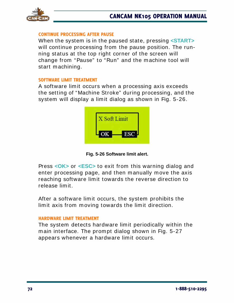
SOFTWARE LIMIT TREATMENTA software limit occurs when a processing axis exceeds the setting of “Machine Stroke” during processing, and the system will display a limit dialog as shown in Fig. 5-26.
Fig. 5-26 Software limit alert.
Press <OK> or <ESC> to exit from this warning dialog and enter processing page, and then manually move the axis reaching software limit towards the reverse direction to release limit.
After a software limit occurs, the system prohibits the limit axis from moving towards the limit direction.
HARDWARE LIMIT TREATMENTThe system detects hardware limit periodically within the main interface. The prompt dialog shown in Fig. 5-27 appears whenever a hardware limit occurs.
72 1-888-510-2295

OPERATION INSTRUCTIONS
Fig. 5-27 Hardware limit alert.
At this time, press <OK> to make the system return to the main interface under “Jog Mode” with “Limit Rls.” dis-played at its bottom right corner.
Or, you can press <ESC> key to go directly back to the main interface under “Jog Mode.”
Move the machine tool away from the limit position, where “Limit Rls.” disappearing. The prompt interface of limit goes back to the normal main interface.
SHUTDOWN & REBOOT Pressing <ESC> for approximately three seconds in the main interface launches a prompt to either reboot or shutdown the system, as shown in Fig. 5-28.
Fig. 5-28 Shutdown/Reboot prompt.
The system will then go blank. If you want to enter the system again, you need to power off and re-power the system.
WWW.CANCAM.CA 73

CANCAM NK105 OPERATION MANUAL
74 1-888-510-2295

MAINTENANCE
As the CNC machine produces lots of dust and debris, maintenance is important to lengthen service life and improve production efficiency. First, you should have a general understanding of the structure and working style of the CNC router by reading this operation manual to bet-ter understand the motion of the guide rails, rack and pinion, etc.
It is important that the guide rails are cleaned frequently to ensure the gantry moves smoothly and to avoid deviations in your work. Key components, such as the motor, can wear, causing failure and inaccuracy. As time passes, the screw rod can become deformed, which will seri-ously affect the accuracy of the machine.
Through a basic understanding of the components, it is easy to grasp the key points of main-tenance. The following are important aspects of maintenance.
LUBRICATION Some series of the products our company producers do not have an automatic oil supply sys-tem, so they need to be cleaned manually before and after machining.
WWW.CANCAM.CA 75
CANCAM NK105 OPERATION MANUAL
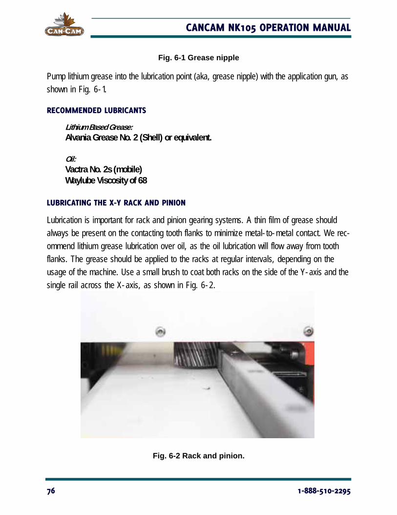
Fig. 6-1 Grease nipple
Pump lithium grease into the lubrication point (aka, grease nipple) with the application gun, as shown in Fig. 6-1.
RECOMMENDED LUBRICANTS
Lithium Based Grease:Alvania Grease No. 2 (Shell) or equivalent.
Oil:Vactra No. 2s (mobile)Waylube Viscosity of 68
LUBRICATING THE X-Y RACK AND PINION
Lubrication is important for rack and pinion gearing systems. A thin film of grease should always be present on the contacting tooth flanks to minimize metal-to-metal contact. We rec-ommend lithium grease lubrication over oil, as the oil lubrication will flow away from tooth flanks. The grease should be applied to the racks at regular intervals, depending on the usage of the machine. Use a small brush to coat both racks on the side of the Y-axis and the single rail across the X-axis, as shown in Fig. 6-2.
Fig. 6-2 Rack and pinion.
76 1-888-510-2295
OPERATION INSTRUCTIONS
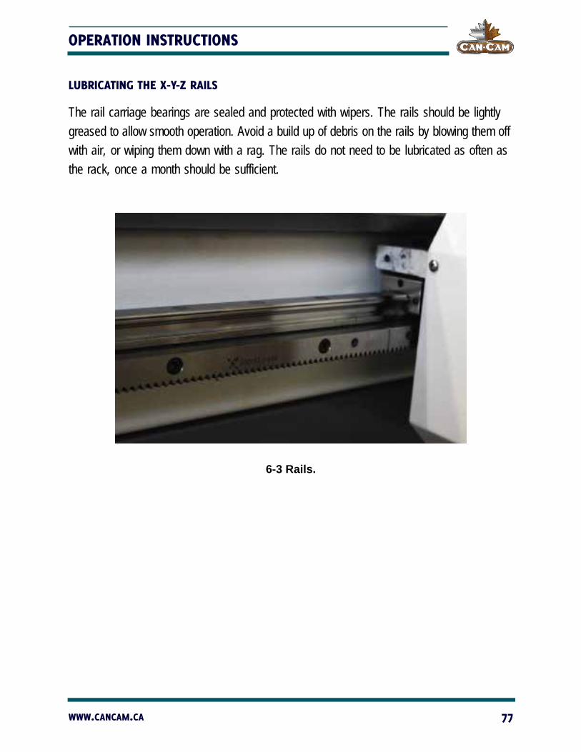
LUBRICATING THE X-Y-Z RAILS
The rail carriage bearings are sealed and protected with wipers. The rails should be lightly greased to allow smooth operation. Avoid a build up of debris on the rails by blowing them off with air, or wiping them down with a rag. The rails do not need to be lubricated as often as the rack, once a month should be sufficient.
6-3 Rails.
WWW.CANCAM.CA 77

CANCAM NK105 OPERATION MANUAL
DAILY MAINTENANCE Check the machine before beginning any machining and clean it after use every day.
Check all wires for damage and connectivity prior to powering up the machine; most impor-tantly, the communication line and power line.
NEVER stand on the machine and keep a safe distance away while under automatic control. Failure to follow these instructions will put
the operator at risk of being severely injured or even killed.
Keep the area around the machine free from chips, dust and coolant to avoid creating slip hazards for the machine.
Check to ensure chips and dust are not caught in the X, Y or Z linear guide rails or rack and pinion/ball screw. Dislodge all chips and thoroughly clean dust.
Lubricate after thorough cleaning.
Clean accumulated chips, dust and coolant off the table to maintain vacuum pump suction.
NOTE: Always power down machine when cleaning guide rails, rack and pinions and ball screw assemblies to avoid injuries.
Ensure there an adequate amount of mister coolant if machine is equipped with Unist system.
At the end of the work day, remove the tool and loosen the spindle chuck and lock nut; this will help lengthen the service life of the spindle chuck. Clean the worktable with a brush, clearing any dust or fragments off the guide rails (if exposed).
DANGER!
78 1-888-510-2295

OPERATION INSTRUCTIONS
Clean the sensors (optical coupler, safety limit switch) to prevent dust and oil from influencing its sensitivity or to avoid setting it off by accident.
Stop the machine with the spindle in a position where it is less likely to get in the way and to avoid collision or leaked oil if over-lubed, and then turn off the power.
REGULAR MAINTENANCE For regular maintenance, it is best to maintain and perform a comprehensive checklist of pro-cedures to be carried out at specified intervals to eliminate potential danger and to restore the machine to its optimal operating state. Generally, this maintenance should be completed every month or 160 hours for two reasons: first, the moving parts of the worktable may loosen or displace over time from regular operation; secondly, grime or fine powders may form during machining, sticking to the lubrication oil and accumulating on the rack and pinion or guide rail, which over time can result in an overload of key components or abnormal grinding. There are three key steps for regular maintenance against the above problems:
STEP ONE: INSPECTION
CHECK the connecting bolts of each component in case they have loosened over time. Key components with bolts would be: guide rail, gantry, support column, bearing block, and machine nose. Adjust fastening bolts to eliminate potential failures.
CHECK that the connecting lines near the operating surface (sensors/motors) are not burnt, damaged, or corroded by chemicals/abnormal use. Find and solve these problems in time to avoid machine damage due to short-circuiting.
CHECK if the rack and pinion on each axis has an axial gap during motion. This process is very important, because dislocation in carving, character deformation, and deviation in “back to relative origin” are all related to this problem. Reasons for axial movement are generally loosening of lock nuts on both sides of the guide rail and damage to bearings. It should first be cleaned prior to adjusting.
WWW.CANCAM.CA 79

CANCAM NK105 OPERATION MANUAL
CHECK for abnormal noises during operation, and troubleshoot for the potential failure to position, which could be caused by the wearing of the guide rail bearings on both sides.
STEP TWO: COMPREHENSIVE CLEANING
Clean grime and any accumulated lubricating oil off the guide rail and bearing blocks.
Turn on power to the machine and move it to clean and lubricate everywhere along the guide rail and rack and pinion.
STEP THREE: LUBRICATION
Lubricate linear guide rails, rack and pinions and ball screw assemblies monthly to ensure peak mechanical performance.Thoroughly clean components of any excess lubrication before fresh coating. Using gloves or a stiff brush, evenly smear a thin layer of No. 2 lithium-based grease on the rack and pinion. Linear guide rails should be lubricated with way lube. Rack and pinion should be lubricated with white lithium grease. Ball screw assemblies should be lubricated via the grease nipple using a grease gun.
Below is a sample maintenance schedule for your use. Fill in the date and year of scheduled maintenance. Technicians can initial completed tasks.
80 1-888-510-2295

OPERATION INSTRUCTIONS
Mon
th D
D/Y
YJA
N
__/_
_FE
B
__/_
_M
AR
__/_
_APR
__
/__
MAY
__
/__
JUN
__
/__
JULY
__
/__
AU
G
__/_
_SEP
__
/__
OCT
__/_
_N
OV
__/_
_D
EC
__/_
_
XY
rac
k an
d p
in-
ion
th
orou
gh
cl
ean
ing
an
d lu
-b
rica
tion
(w
hit
e lit
hiu
m g
reas
e)
XY
Z li
nea
r g
uid
e ra
ils t
hor
oug
h
clea
nin
g a
nd
lu
bri
cati
on (
way
lu
be)
Z a
xis
bal
l scr
ew
lub
rica
tion
(vi
a g
reas
e n
ipp
le)
Cle
anin
g o
f ca
b-
inet
fro
m b
uilt
u
p d
ust
/d
ebri
s
Cle
anin
g o
f co
n-
trol
ler
han
d-
hel
d/
keyb
oard
WWW.CANCAM.CA 81

CANCAM NK105 OPERATION MANUAL
82 1-888-510-2295


