FX2 vLAB Guide - Amazon S3 · 2 LAB 2: Initial Configuration ... 3.5.2 Updating the Chassis CMC ......
69
PowerEdge FX2 vLab Guide Demos.dell.com – Server Domain Dell confidential Document Version 1.1 Date: June 2015
Transcript of FX2 vLAB Guide - Amazon S3 · 2 LAB 2: Initial Configuration ... 3.5.2 Updating the Chassis CMC ......

Dell | Global Sales Learning & Development
Page 1 of 69
Dell confidential
PowerEdge FX2 vLab Guide Demos.dell.com – Server Domain
Dell confidential
Document Version 1.1
Date: June 2015
Dell | Global Sales Learning & Development
Page 2 of 69
Dell confidential
Table of Contents
Demonstration Labs ........................................................................................................................... 5
Introduction ............................................................................................................................................ 5
Preparing the Demo Environment ..................................................................................................... 5
Preparing your agenda for the demonstration ................................................................................ 8
Pre-Demo - Introducing the customer to the demo ..................................................................... 9
Set the Scene ........................................................................................................................................ 10
1 LAB 1: Basic Navigation of the FX2 CMC ....................................................................... 11
1.1 Introduction/Customer Challenge ....................................................................................... 11
1.2 Business Talking Points: ......................................................................................................... 11
1.3 Technical Selling Points: ........................................................................................................ 12
1.4 Technical Objections and Query Handling: ....................................................................... 13
1.5 Lab 1: Logging on – [Step by Step] ..................................................................................... 14
2 LAB 2: Initial Configuration ............................................................................................. 16
2.1 Introduction .............................................................................................................................. 16
2.2 Talking Points: .......................................................................................................................... 17
2.3 Technical Selling Points: ........................................................................................................ 17
2.4 Technical Objections and Query Handling ........................................................................ 17
2.5 Lab 2: Initial Configuration – [Step by Step] ...................................................................... 17
3 LAB 3: Firmware Updates ................................................................................................. 19
3.1 Introduction .............................................................................................................................. 19
3.2 Talking Points: ......................................................................................................................... 20
3.3 Technical Selling Points: ...................................................................................................... 20
3.4 Technical Objections and Query Handling ....................................................................... 20
3.5 Lab 3: Firmware Updates – [Step by Step] ........................................................................ 20
3.5.1 Setup a Network Share .................................................................................................. 20
3.5.2 Updating the Chassis CMC ............................................................................................ 21
3.5.3 Updating Server BIOS/Firmware from file ................................................................... 21
3.5.4 Updating Server BIOS/Firmware from network share ..............................................23
Dell | Global Sales Learning & Development
Page 3 of 69
Dell confidential
4 LAB 4: Chassis Power Monitoring & Configuration .................................................... 24
4.1 Introduction ............................................................................................................................. 24
4.2 Talking Points: ..........................................................................................................................25
4.3 Technical Selling Points: ........................................................................................................25
4.4 Technical Objections and Query Handling ........................................................................25
4.5 Lab 4: Chassis Power Settings – [Step by Step] ............................................................... 26
4.5.1 Check the real-time power consumption of the chassis ....................................... 26
4.5.2 Configure remote logging and redundancy ............................................................... 27
5 LAB 5: Server Profiles ....................................................................................................... 28
5.1 Introduction ............................................................................................................................. 28
5.2 Talking Points: ......................................................................................................................... 28
5.3 Technical Selling Points: ....................................................................................................... 29
5.4 Technical Objections and Query Handling ...................................................................... 29
5.5 Lab 5: Server Profiles – [Step by Step] ............................................................................... 29
5.5.1 Save a Profile ................................................................................................................... 29
5.5.2 Apply a Profile.................................................................................................................. 30
5.5.3 Profiles for QuickDeploy ................................................................................................ 31
6 LAB 6: KVM Assignment ...................................................................................................32
6.1 Introduction ..............................................................................................................................32
6.2 Talking Points: ..........................................................................................................................32
6.3 Technical Selling Points: ........................................................................................................32
6.4 Technical Objections and Query Handling ........................................................................32
6.5 Lab 6: KVM Assignment – [Step by Step] ...........................................................................33
7 LAB 7: Chassis Grouping .................................................................................................. 33
7.1 Introduction ..............................................................................................................................33
7.2 Talking Points: ......................................................................................................................... 34
7.3 Technical Selling Points: ....................................................................................................... 34
7.4 Technical Objections and Query Handling ....................................................................... 34
7.5 Lab 7: Chassis Grouping – [Step by Step] ......................................................................... 34
7.5.1 Create a new group ........................................................................................................... 34
Dell | Global Sales Learning & Development
Page 4 of 69
Dell confidential
7.5.2 Add a member to the group ......................................................................................... 36
7.5.3 Propagate Chassis Properties ....................................................................................... 38
7.5.4 Chassis Group Firmware ................................................................................................ 41
7.5.5 Remove a Member from a group ................................................................................ 42
7.5.6 Disband the Group ......................................................................................................... 43
8 LAB 8: Networking ........................................................................................................... 44
8.1 Introduction ............................................................................................................................. 44
8.2 Talking Points: ......................................................................................................................... 44
8.3 Technical Selling Points: ....................................................................................................... 44
8.4 Technical Objections and Query Handling ....................................................................... 44
8.5 Lab 8: Networking with the FN IOA – [Step by Step] ..................................................... 45
8.5.1 Configure IP Settings ..................................................................................................... 45
8.5.2 Configure Untagged VLAN ........................................................................................... 46
8.5.3 Add Tagged VLANs ......................................................................................................... 49
8.5.4 Remove Tagged VLANs .................................................................................................. 51
8.5.5 Copy VLAN Settings Between FN IOAs .......................................................................53
8.5.6 Reset to All VLANs ........................................................................................................... 55
8.5.7 Rebooting FN IOAs .......................................................................................................... 57
8.5.8 Resetting FN IOAs ........................................................................................................... 58
8.5.8 Checking Port Status ..................................................................................................... 59
8.5.9 IOM Firmware Update ................................................................................................... 60
9 LAB 9: Storage and PCIe Mappings ................................................................................ 61
9.1 Introduction .............................................................................................................................. 61
9.2 Talking Points: .......................................................................................................................... 61
9.3 Technical Selling Points: ........................................................................................................ 61
9.4 Technical Objections and Query Handling ........................................................................ 61
9.5 Lab 9: Storage and PCIe Mappings – [Step by Step] ...................................................... 62
9.5.1 Dual Controller FD332 ................................................................................................... 62
9.5.2 Single Controller FD332 ................................................................................................. 67
9.5.3 PCIe Mappings ................................................................................................................ 68
Dell | Global Sales Learning & Development
Page 5 of 69
Dell confidential
Demonstration Labs
Introduction
Overview of solution
The FX2 is a 2U rack-based converged platform that combines powerful server and storage blocks in a compact rack-based infrastructure with shared power, cooling, networking, management and IO expansion capabilities.
Overview of demo
This document provides details on “HOW” to deliver an effective live demonstration of the PowerEdge FX2 to customers.
In this demo you will perform the following tasks;
Logon to a FX2 chassis and review hardware
Review PowerEdge FX2 CMC Console basic navigation (ease of use and navigation)
Navigate how to perform a firmware updates
Investigate chassis power settings
Configure server profiles with the FX2 chassis
Review KVM assignment
Create a new group for FX2’s
Additional Notes
This demo is based on a simulator instance, which can be used both online or offline.
However due to it being a simulator of the actual PowerEdge FX2, it does not behave
dynamically and has been created in accordance to this guide specially, so any deviation
from this guide will not accurately reflect what would happen on an actual physical
PowerEdge FX2.
Preparing the Demo Environment
It is in your best interests to ensure the demo environment you will be demonstrating is clean
& tidy before you begin. For this reason we would recommend, where possible, you log in to
your demo at least 15mins prior to delivery and check the following;

Dell | Global Sales Learning & Development
Page 6 of 69
Dell confidential
Familiarise yourself with the environment during this time and check any specific
features you are expecting to demo.
Most importantly, be crystal clear with yourself on what it is you plan to show. A full
demo of every feature described below (with questions) can take several hours. If you
only have a short time slot be sure to focus on the key points that address the
customer’s pain points and will drive value home to them.
The simulator has no time restriction and does not have to be booked. It can used on
demand.
Note that the FX2 demo is found under the Simulators tab.

Dell | Global Sales Learning & Development
Page 7 of 69
Dell confidential
Select 13G PowerEdge FX2 and click Connect to launch the demo.
The simulator can also be downloaded for offline use when not connected to the
internet.
Use Internet Explorer for the demo as it has been noted that there may be some
issues with other browsers.
Dell | Global Sales Learning & Development
Page 8 of 69
Dell confidential
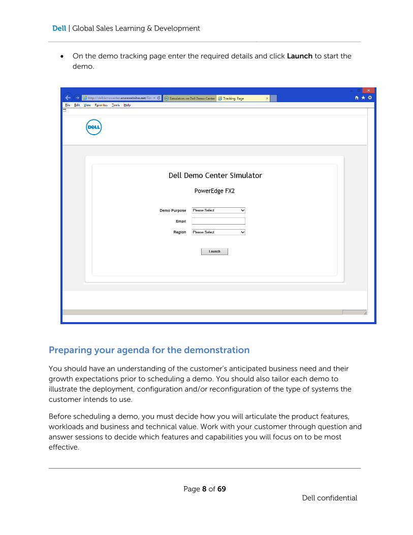
On the demo tracking page enter the required details and click Launch to start the
demo.
Preparing your agenda for the demonstration
You should have an understanding of the customer’s anticipated business need and their
growth expectations prior to scheduling a demo. You should also tailor each demo to
illustrate the deployment, configuration and/or reconfiguration of the type of systems the
customer intends to use.
Before scheduling a demo, you must decide how you will articulate the product features,
workloads and business and technical value. Work with your customer through question and
answer sessions to decide which features and capabilities you will focus on to be most
effective.

Dell | Global Sales Learning & Development
Page 9 of 69
Dell confidential
The idea is not to present a “How-To” session, but to focus on the value of the product
and/or solution. Even if the customer representative is not overly technical, you can
demonstrate what the product does and how that can benefit the customer.
You should have a good understanding of the customer’s current infrastructure and workloads:
o Datacenter needs o Workloads: Traditional/Hosting/Software Defined Data Centre (SDDC) o Operating Systems & Key Applications (Database types etc.) o Server, Network and Storage Platforms o Reporting/Management Tools
Understand the customer’s desired infrastructure ‘Wins’ Examples:
o Deployment automation o Ease of Management of Data center o Application requirements o Storage requirements o Data growth projections o TCO (Total cost of ownership) o ROI (Return of investment) o …add relevant areas of interest to the customer or based on the demo solution
Pre-Demo - Introducing the customer to the demo
Your introduction will be based on what you know of the customer, their infrastructure,
needs, and plans for development. The following is a suggested set of items to cover before
you demonstrate the features and benefits of the PowerEdge FX2.
Understand Customer’s Desired infrastructure ‘Wins’
o Simplified remote management/lifecycle management o Flexible and quiet operations o Reduce Cost of Management o Reduce total cost of ownership (TCO) o …add relevant areas of interest to the customer or based on the demo solution

Dell | Global Sales Learning & Development
Page 10 of 69
Dell confidential
Review Assessment data
o Discuss customer’s requirements o Workload requirements o Application and Storage/Networking requirements o Demonstrate understanding of customer’s business as it relates to their data
requirements o …add relevant areas of interest to the customer or based on the demo solution
PowerEdge FX2 Overview
o Explain the key features and benefits of the PowerEdge FX2 Solution o Give an overview of deployment options o Discuss Dell’s POV o Positioning - Explain what PowerEdge FX2 is NOT!
Services – Consulting, Delivery & Technical Support
o Explain the roles of Consulting, Service Delivery/Deployment & Technical Support in successful deployments of the PowerEdge FX2.
Pre-Demo points to cover
o Ensure that you understand who you are presenting to and how the benefits of the system will enable them to ‘win’ in their roles.
Set the Scene
It can be easy to forget that the customer has no idea what it is they are looking at, so take some time emphasizing the following;
o Explain that the purpose is to demonstrate the benefits and key features, not to
provide a “How To” session
o Explain that the demo is a simulator of physical hardware to provide a demonstration
of the features and capabilities that will be covered
o Set up and current configuration information
o Connectivity methods that you will be using (HTTP)
o Introduce the management interfaces you plan to use (PowerEdge FX2 CMC)
Are there any short videos for the FX2?
Yes, we have several available on Dell’s YouTube channel (Dell or QRLDell).
Dell PowerEdge FX Architecture
PowerEdge FN IO Aggregator
Dell | Global Sales Learning & Development
Page 11 of 69
Dell confidential
Endless Possibilities – PowerEdge FX2
Dell PowerEdge FX Architecture
PowerEdge FX Architecture Redefining the Converged Data Centre
Dell QR Code – Removal of Chassis components – Playlist of 13 individual videos
1 LAB 1: Basic Navigation of the FX2 CMC
1.1 Introduction/Customer Challenge
This demonstration is primarily aimed at the CIO/CFO level and IT management staff, it also provides a useful quick introduction for staff who are not familiar with PowerEdge FX2. Provisioning any production IT infrastructure from bare-metal to fully-functional infrastructure is a complex task that typically requires a high-level technical resource operating full-time for an extended period of time. This is a technical demo (but not a technically-detailed installation) that illustrates how the PowerEdge FX2 can significantly reduce the workload on this type of technical IT resource. The demo is compelling in terms of demonstrating the productivity and management benefits of the PowerEdge FX2. You can, and should, give this level of demo in 5 to 10 minutes. You want the customer to think “Whow that was easy”! If you frame the discussion correctly during the demo, you will get the desired reaction.
In this lab you will be performing the following tasks:
Setting the scene for the customer
Logon to the PowerEdge FX2 CMC
Navigate around the chassis
1.2 Business Talking Points:
Explain the current system configuration in terms of:
o Chassis Configuration
o Remote Console features

Dell | Global Sales Learning & Development
Page 12 of 69
Dell confidential
It may have been some time since the customer was introduced to the CMC so use this overview of the system as an opportunity to refresh the customer on the most relevant points of the CMC.
PowerEdge FX Chassis Management Controller provides a single pane of glass to manage your FX, server and components.
1.3 Technical Selling Points:
Ease of use is the key point here with the ability to simply manage the system from a web interface.
Power may be an issue for customers within the data center. The PowerEdge FX2 can help to address some of the Power limitations by way of its Power Management features

Dell | Global Sales Learning & Development
Page 13 of 69
Dell confidential
1.4 Technical Objections and Query Handling:
Question: What are the Networking options?
Answer: The FX2 can has 2 network slots at the back. These can house a pass-
through module or an IOA. There are 3 SKU options for the IOA:
4 x 10GbE SFP+
4 x 10GbE Base-T
2 x 10GbE SFP+ and 2 x 2/4/8G Fibre Channel Combo
All SKUs have 8 x 10GbE internal ports.
Question: What about PCI cards?
Answer: FX2s chassis support low profile cards – the same low profile cards
supported in the PowerEdge Racks. Much like the racks, the slots have 24
watt limitations.
You can install a PCIe card into the chassis without powering the chassis
down, but you will have to power down the sled associated with the PCIe
card to have it recognize and use the PCIe card.
At this time PCI slots are assigned to specific blades and cannot be re-
mapped.
Question: What behavior does the chassis exhibit if the CMC fails?
Answer: Fans will go to 100% speed and new servers will not be allowed to power
on.
Question: What happens when I plug in two network cables to the CMC when it’s in stacking mode?
Answer: Connecting the STK/Gb2 port to the management network without first
configuring for redundancy in the CMC can have unpredictable results.
Cabling Gb1 and STK/Gb2 to the same network (broadcast domain) can
cause a broadcast storm.
Gotchas:
The FX2 differs from the M1000e in that the KVM must be assigned to one of the blades and
is not used for management of the FX2 chassis. This means a web browser running on a host
Dell | Global Sales Learning & Development
Page 14 of 69
Dell confidential
on the 192.168.0.0/24 network is required for initial setup. The default management URL of
the FX2 is: http://192.168.0.120
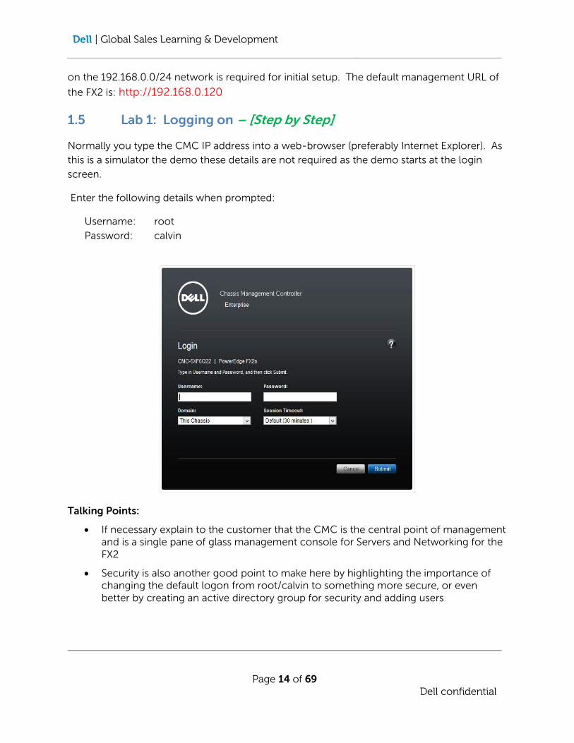
1.5 Lab 1: Logging on – [Step by Step]
Normally you type the CMC IP address into a web-browser (preferably Internet Explorer). As
this is a simulator the demo these details are not required as the demo starts at the login
screen.
Enter the following details when prompted:
Username: root
Password: calvin
Talking Points:
If necessary explain to the customer that the CMC is the central point of management and is a single pane of glass management console for Servers and Networking for the FX2
Security is also another good point to make here by highlighting the importance of changing the default logon from root/calvin to something more secure, or even better by creating an active directory group for security and adding users
Dell | Global Sales Learning & Development
Page 15 of 69
Dell confidential
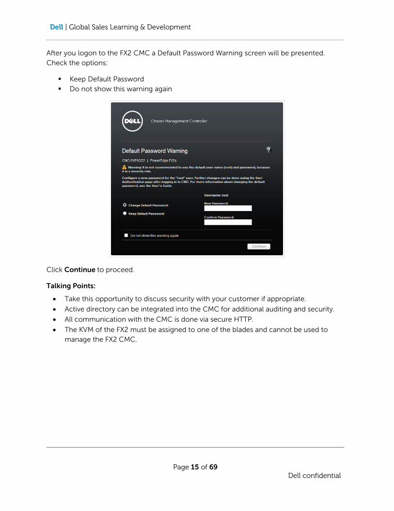
After you logon to the FX2 CMC a Default Password Warning screen will be presented.
Check the options:
Keep Default Password
Do not show this warning again
Click Continue to proceed.
Talking Points:
Take this opportunity to discuss security with your customer if appropriate.
Active directory can be integrated into the CMC for additional auditing and security.
All communication with the CMC is done via secure HTTP.
The KVM of the FX2 must be assigned to one of the blades and cannot be used to
manage the FX2 CMC.

Dell | Global Sales Learning & Development
Page 16 of 69
Dell confidential
Chassis Overview
Navigate to Chassis Overview on the left hand side and select it.
Talking Points:
Call attention to the physical components Front, Rear, and internal views. Alert Status.
Hover or drill down into some of the individual components to demonstrate the level
of detail that is available.
2 LAB 2: Initial Configuration
2.1 Introduction
In this Lab you will be performing the following tasks:
Allow Network access to the CMC.
Configure QuickDeploy settings.
Set access details on the server iDRACs for server management.

Dell | Global Sales Learning & Development
Page 17 of 69
Dell confidential
2.2 Talking Points:
This lab covers the minimum setup of an FX2 to connect it to the customer’s management
network and prepare the servers in the chassis for out-of-band management. In addition
QuickDeploy settings will be configured so that any new servers inserted into the chassis will
be automatically configured for management without needing to return to the CMC to set
them up.
2.3 Technical Selling Points:
Single pane of glass for setup of the chassis and all the servers installed. Also, once
QuickDeploy has been configured all new servers inserted into the chassis will be
immediately available for management without any setup.
Server profiles which change the BIOS, RAID and NIC partitioning settings can also be
configured as part of the QuickDeploy. Profiles will be covered in a later lab.
2.4 Technical Objections and Query Handling
Question: Can QuickDeploy settings be used across chassis in a group?
Answer: No. The QuickDeploy settings are only for blades within a single chassis.
QuickDeploy settings need to be configured on all chassis individually.
Gotcha’s
NOTE: In production, once the IP address of the CMC is changed the CMC network port will
need to be reconnected to the appropriate network VLAN for the IP address entered. A new
browser session will need to be opened to the new CMC management address.
2.5 Lab 2: Initial Configuration – [Step by Step]
In the Chassis Overview section select the Network Tab. In the IPv4 sub-section on the
Network page set the following attributes:
Static IP Address: 192.168.0.130
Static Netmask: 255.255.255.0
Static Gateway: 192.168.0.1

Dell | Global Sales Learning & Development
Page 18 of 69
Dell confidential
Click Apply Changes, then click OK on the warning pop-up.
NOTE: In production if the IP address changes to a different network the CMC NIC will
have to be patched to the new network.
In the Server Overview section select the Setup tab. On the iDRAC page change the
following attributes:
Action When Server is Inserted QuickDeploy Only
Set iDRAC Root password on Server Insertion
iDRAC Root Password calvin
Confirm iDRAC Root Password calvin
Enable iDRAC LAN
Enable iDRAC IPv4
Enable iDRAC IMPI over LAN
Enable iDRAC IPv4 DHCP
Reserved QuickDeploy IP Addresses 4 IP Addresses (Click OK in the pop-up box)
Starting iDRAC IPv4 Address (Slot 1) 192.168.0.131
iDRAC IPv4 Netmask 255.255.255.0
iDRAC IPv4 Gateway 192.168.0.1
Enable iDRAC IPv6
Click Save QuickDeploy Settings
Click OK on the QuickDeploy settings pop-up.
Click OK on the Operation Successful pop-up.
In the iDRAC Network Settings sub-section click Auto-Populate Using QuickDeploy Settings
Dell | Global Sales Learning & Development
Page 19 of 69
Dell confidential
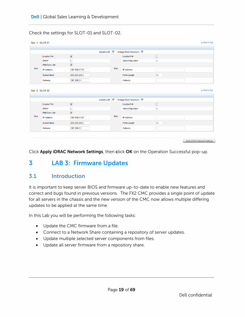
Check the settings for SLOT-01 and SLOT-02.
Click Apply iDRAC Network Settings, then click OK on the Operation Successful pop-up.
3 LAB 3: Firmware Updates
3.1 Introduction
It is important to keep server BIOS and firmware up-to-date to enable new features and
correct and bugs found in previous versions. The FX2 CMC provides a single point of update
for all servers in the chassis and the new version of the CMC now allows multiple differing
updates to be applied at the same time.
In this Lab you will be performing the following tasks:
Update the CMC firmware from a file.
Connect to a Network Share containing a repository of server updates.
Update multiple selected server components from files.
Update all server firmware from a repository share.

Dell | Global Sales Learning & Development
Page 20 of 69
Dell confidential
3.2 Talking Points:
The CMC provides a single pane of glass for management of server updates for one or many
servers simultaneously. The new CMC can update multiple server components at the same
time. No more waiting for one update to complete before commencing another.
Updates can be done via file for selective updates or via a network share option that allows a
Dell Repository Manager to create a full update bundle for the blades and apply all available
updates at one time. Note that this option does not have the ability to update selected
components the way a file update can.
3.3 Technical Selling Points:
The CMC provides multiple update methods for the servers on a selected component or all
available updates basis. Since server operating systems are not controller by the CMC, the
firmware can be upgraded without impacting running servers.
3.4 Technical Objections and Query Handling
Question: Is the CMC firmware the same for FX2, VRTX and M1000e.
Answer: Built off of the same code base but firmware images are unique for FX2,
M1000e and VRTX. Ensure you download the correct version from the Dell
support website: http://support.dell.com
3.5 Lab 3: Firmware Updates – [Step by Step]
3.5.1 Setup a Network Share
First connect to a Network Share in order to point the FX2 to the update file. In the Server
Overview Section select the Setup tab and go to the Network Share page.
Set the following attributes:
Protocol CIFS
IP Address or Host Name 192.168.0.110
Share Name FX2
Update Folder Updates
Dell | Global Sales Learning & Development
Page 21 of 69
Dell confidential
Profile Folder Profiles
User Name FX2
Password Password01
Click Apply to save the settings.
Click OK in the Operation Successful pop-up.
Click the Test Directory button beside each directory.
Click OK on the Test Passed pop-up.
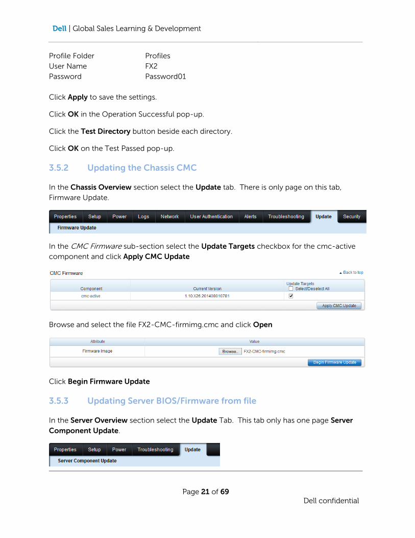
3.5.2 Updating the Chassis CMC
In the Chassis Overview section select the Update tab. There is only page on this tab,
Firmware Update.
In the CMC Firmware sub-section select the Update Targets checkbox for the cmc-active
component and click Apply CMC Update
Browse and select the file FX2-CMC-firmimg.cmc and click Open
Click Begin Firmware Update
3.5.3 Updating Server BIOS/Firmware from file
In the Server Overview section select the Update Tab. This tab only has one page Server
Component Update.
Dell | Global Sales Learning & Development
Page 22 of 69
Dell confidential
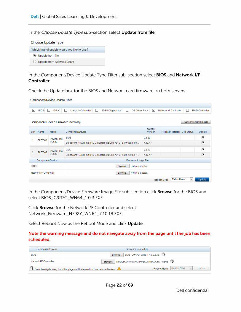
In the Choose Update Type sub-section select Update from file.
In the Component/Device Update Type Filter sub-section select BIOS and Network I/F
Controller
Check the Update box for the BIOS and Network card firmware on both servers.
In the Component/Device Firmware Image File sub-section click Browse for the BIOS and
select BIOS_C9R7C_WN64_1.0.3.EXE
Click Browse for the Network I/F Controller and select
Network_Firmware_NF92Y_WN64_7.10.18.EXE
Select Reboot Now as the Reboot Mode and click Update
Note the warning message and do not navigate away from the page until the job has been
scheduled.

Dell | Global Sales Learning & Development
Page 23 of 69
Dell confidential
3.5.4 Updating Server BIOS/Firmware from network share
In the Choose Update Type sub-section select Update from network share.
In the Network Share Properties sub-section click Check for Updates
The repository on the share is checked for updates and any updates available are shown in
the Component/Device Firmware Inventory sub-section. Select SLOT-01 and deselect
SLOT-02. Change the Reboot Mode to Reboot Now and click Update
Click OK on the warning pop-up.
The system will now re-check for updates and submit a job to the Lifecycle Controller to
update the server. Wait for the Status to change to
before proceeding.
Dell | Global Sales Learning & Development
Page 24 of 69
Dell confidential
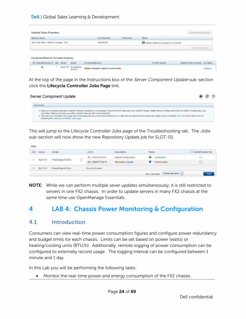
At the top of the page in the Instructions box of the Server Component Update sub-section
click the Lifecycle Controller Jobs Page link.
This will jump to the Lifecycle Controller Jobs page of the Troubleshooting tab. The Jobs
sub-section will now show the new Repository Update job for SLOT-01.
NOTE: While we can perform multiple sever updates simultaneously, it is still restricted to
servers in one FX2 chassis. In order to update servers in many FX2 chassis at the
same time use OpenManage Essentials.
4 LAB 4: Chassis Power Monitoring & Configuration
4.1 Introduction
Consumers can view real-time power consumption figures and configure power redundancy
and budget limits for each chassis. Limits can be set based on power (watts) or
heating/cooling units (BTU/h). Additionally, remote logging of power consumption can be
configured to externally record usage. The logging interval can be configured between 1
minute and 1 day.
In this Lab you will be performing the following tasks:
Monitor the real-time power and energy consumption of the FX2 chassis.
Dell | Global Sales Learning & Development
Page 25 of 69
Dell confidential
Configure a remote logging server.
Learn how to configure a power cap on the chassis.
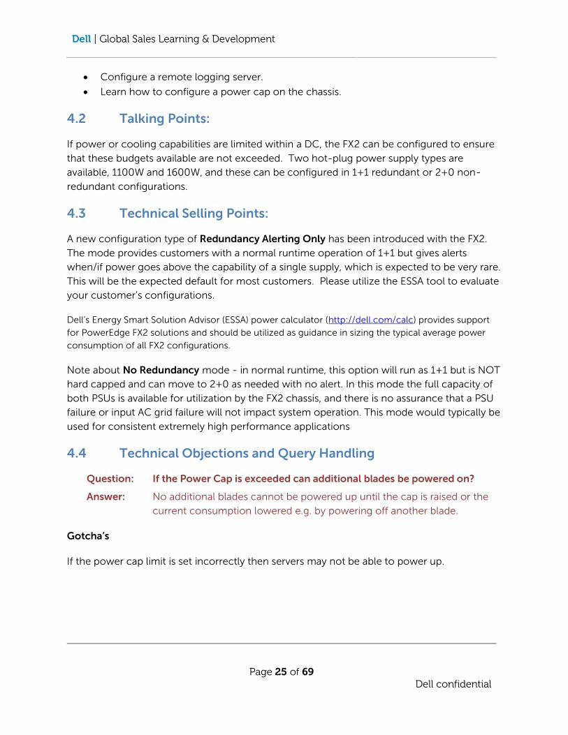
4.2 Talking Points:
If power or cooling capabilities are limited within a DC, the FX2 can be configured to ensure
that these budgets available are not exceeded. Two hot-plug power supply types are
available, 1100W and 1600W, and these can be configured in 1+1 redundant or 2+0 non-
redundant configurations.
4.3 Technical Selling Points:
A new configuration type of Redundancy Alerting Only has been introduced with the FX2.
The mode provides customers with a normal runtime operation of 1+1 but gives alerts
when/if power goes above the capability of a single supply, which is expected to be very rare.
This will be the expected default for most customers. Please utilize the ESSA tool to evaluate
your customer’s configurations.
Dell’s Energy Smart Solution Advisor (ESSA) power calculator (http://dell.com/calc) provides support
for PowerEdge FX2 solutions and should be utilized as guidance in sizing the typical average power
consumption of all FX2 configurations.
Note about No Redundancy mode - in normal runtime, this option will run as 1+1 but is NOT
hard capped and can move to 2+0 as needed with no alert. In this mode the full capacity of
both PSUs is available for utilization by the FX2 chassis, and there is no assurance that a PSU
failure or input AC grid failure will not impact system operation. This mode would typically be
used for consistent extremely high performance applications
4.4 Technical Objections and Query Handling
Question: If the Power Cap is exceeded can additional blades be powered on?
Answer: No additional blades cannot be powered up until the cap is raised or the
current consumption lowered e.g. by powering off another blade.
Gotcha’s
If the power cap limit is set incorrectly then servers may not be able to power up.

Dell | Global Sales Learning & Development
Page 26 of 69
Dell confidential
4.5 Lab 4: Chassis Power Settings – [Step by Step]
4.5.1 Check the real-time power consumption of the chassis
In the Chassis Overview section select the Power tab.
Select the Power Monitoring page to view the real-time power and energy consumption
figures.
Dell | Global Sales Learning & Development
Page 27 of 69
Dell confidential
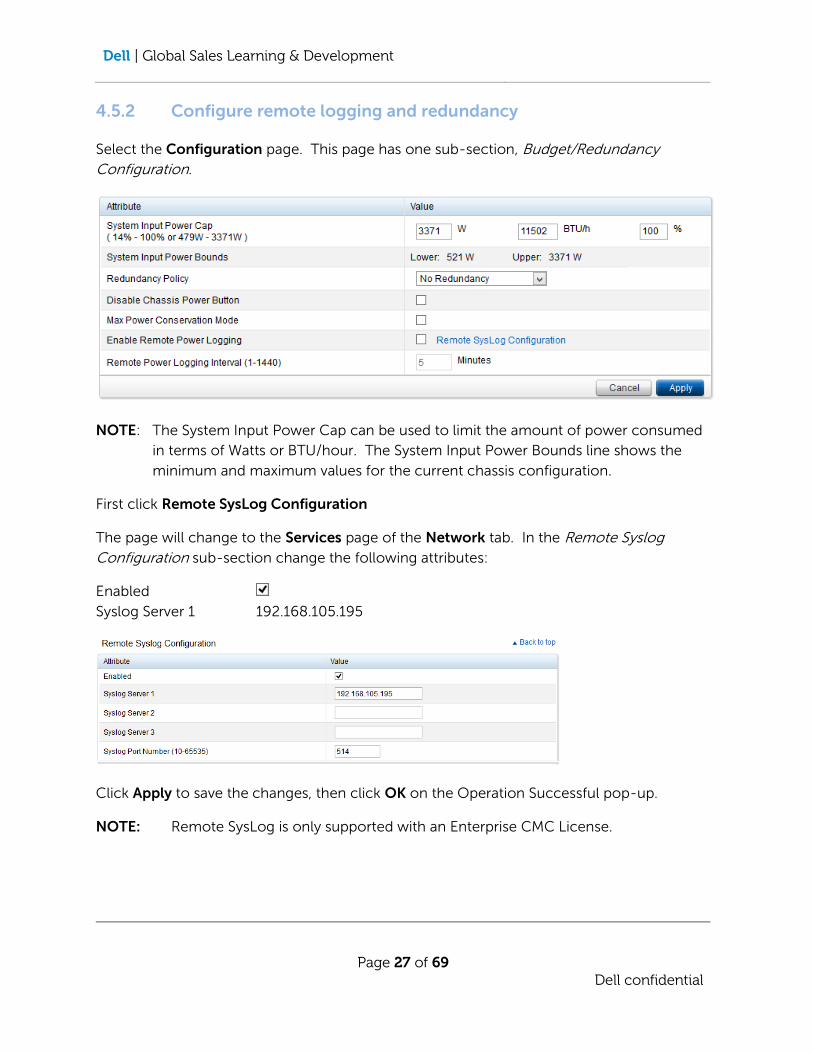
4.5.2 Configure remote logging and redundancy
Select the Configuration page. This page has one sub-section, Budget/Redundancy
Configuration.
NOTE: The System Input Power Cap can be used to limit the amount of power consumed
in terms of Watts or BTU/hour. The System Input Power Bounds line shows the
minimum and maximum values for the current chassis configuration.
First click Remote SysLog Configuration
The page will change to the Services page of the Network tab. In the Remote Syslog
Configuration sub-section change the following attributes:
Enabled
Syslog Server 1 192.168.105.195
Click Apply to save the changes, then click OK on the Operation Successful pop-up.
NOTE: Remote SysLog is only supported with an Enterprise CMC License.

Dell | Global Sales Learning & Development
Page 28 of 69
Dell confidential
Return to the Configuration page of the Power tab.
Change the following attributes:
Redundancy Policy Redundancy Alerting Only
Enable Remote Power Logging
Remote Power Logging Interval (1-1440) 1 Minutes
Click Apply to save the changes, then click OK on the Operation Successful pop-up.
After 1 minute the remote syslog server can be checked for power consumption messages.
They will appear as:
Dec 17 10:09:25 CMC-5XF6Q22 psud: [chassis_power_consumption min=90 max=92 avg=90] #{0000000000}
5 LAB 5: Server Profiles
5.1 Introduction
Server profiles allow the configuration information from one server to be applied to other
servers. The information includes BIOS settings, RAID configuration and NIC setup, including
partitioning (NPAR) settings. This information is saved in an XML format and can be stored
locally on an SD card in the chassis or on a network share to allow the profiles to be applied
to servers in other FX2s. These profiles can also be setup for QuickDeploy so that they are
automatically applied to servers inserted into particular slots. Profiles will significantly speed
up the time to deployment by automatically preparing hardware for use.
In this Lab you will be performing the following tasks:
Capture a server profile and save it to the network
Apply the saved profile to a different server
Setup a QuickDeploy profile to be applied to servers as they are inserted
5.2 Talking Points:
Server profiles saved from an FC630 can be deployed to other rack and blade servers, not
just to other FC630s. Any specific settings for the FC630 will be ignored if they do not apply
to the target server. Most settings in the BIOS such as processor settings, performance
profile, RAID and NIC should apply cross-hardware ok.

Dell | Global Sales Learning & Development
Page 29 of 69
Dell confidential
5.3 Technical Selling Points:
Server profiles will significantly speed up deployment time. As soon a new server is inserted
into the chassis, the management IP will be set, BIOS configured, RAID setup and NIC setup.
So on initial power-up the server will be ready for O/S installation. A library of profiles can be
maintained for different configurations and these can be applied as needed to servers via the
iDRAC at any time. This does not have to be done through the CMC.
5.4 Technical Objections and Query Handling
Question: What if Intel NICs are installed in a blade and a profile with Broadcom NICs is applied?
Answer: The network section of the profile will not be applied to the server, but
BIOS and RAID updates will be applied.
Gotcha’s
When applying a server profile the server will need to reboot to the lifecycle controller in
order to apply the changes.
5.5 Lab 5: Server Profiles – [Step by Step]
This lab uses the Network Share prepared in section 3.5.1
5.5.1 Save a Profile
In the Server Overview section go to the Setup tab and select the Profiles page.
Click Apply and Save Profiles and check the box for SLOT-01 and then click Save Profile
Note: The Save Profile link will not be enabled until a server is selected.
In the Stored Profiles sub-section set the following attributes:

Dell | Global Sales Learning & Development
Page 30 of 69
Dell confidential
Profile Location: Network Share
Profile Name: FC630-01
Note: The Description field will be hidden when Network Share is selected as the location.
Click Save Profile and click OK on the Operation Successful pop-up.
When the profile has completed saving it will appear in the Stored Profiles sub-section. This
is an XML file which can be edited on the network share. Any additional XML files placed in
this folder will automatically appear in the list.
5.5.2 Apply a Profile
Check the box for server SLOT-02. The profile dropdown list will now be enabled.
Select the SHR-FC630-01 profile and click Apply Profile (this will be enabled once a profile is
selected).
Click OK on the warning pop-up and then OK on the Operation Successful pop-up.
Note: ‘SHR-’ is pre-pended to the profile name entered in the previous section to indicate
that this profile is saved on a network rather than on the local SD card.
Dell | Global Sales Learning & Development
Page 31 of 69
Dell confidential
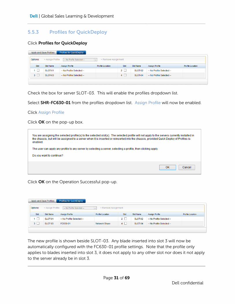
5.5.3 Profiles for QuickDeploy
Click Profiles for QuickDeploy
Check the box for server SLOT-03. This will enable the profiles dropdown list.
Select SHR-FC630-01 from the profiles dropdown list. Assign Profile will now be enabled.
Click Assign Profile
Click OK on the pop-up box.
Click OK on the Operation Successful pop-up.
The new profile is shown beside SLOT-03. Any blade inserted into slot 3 will now be
automatically configured with the FC630-01 profile settings. Note that the profile only
applies to blades inserted into slot 3, it does not apply to any other slot nor does it not apply
to the server already be in slot 3.

Dell | Global Sales Learning & Development
Page 32 of 69
Dell confidential
6 LAB 6: KVM Assignment
6.1 Introduction
Customers may have a need to connect a physical keyboard, mouse and video (KVM) to the
blades in an FX2. There are VGA screen and USB port connections at the front of the FX2 for
connection to a crash-cart in the data centre. This KVM port can be assigned to one of the
blades via the CMC.
The FX2 KVM is different from the M1000e in that the assignment is physically to one of the
blades and is not used to manage the CMC. There is no software switch between blades
from the KVM. Also note that the chassis power button can be disabled from this section to
prevent accidental shutdown of all blades at once.
In this Lab you will be performing the following tasks:
Learn the difference between an FX2 and M1000e KVM
Connect a blade to the front KVM ports of the FX2.
6.2 Talking Points:
The FX2 has a single KVM port that can be connected to any of the servers installed in the chassis. Unlike the M1000e the KVM must be assigned via to a specific server using the CMC. The M1000e allows the selected server to be changed via the KVM keyboard.
6.3 Technical Selling Points:
The chassis power button can be disabled from the KVM setup section to prevent accidental
shutdown of all blades at once.
6.4 Technical Objections and Query Handling
Question: Can the KVM assignment to a specific server be changed via the keyboard, as in the M1000e.
Answer: No. The server assignment must be done via the CMC.
Question: Can the KVM be used to manage the CMC via cli.
Answer: No. The KVM can only be connected to one of the servers, not to the
chassis CMC.
Dell | Global Sales Learning & Development
Page 33 of 69
Dell confidential
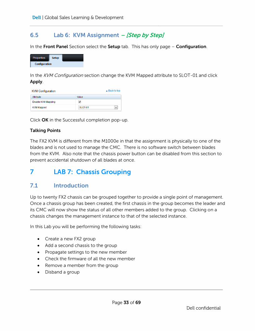
6.5 Lab 6: KVM Assignment – [Step by Step]
In the Front Panel Section select the Setup tab. This has only page – Configuration.
In the KVM Configuration section change the KVM Mapped attribute to SLOT-01 and click
Apply.
Click OK in the Successful completion pop-up.
Talking Points
The FX2 KVM is different from the M1000e in that the assignment is physically to one of the
blades and is not used to manage the CMC. There is no software switch between blades
from the KVM. Also note that the chassis power button can be disabled from this section to
prevent accidental shutdown of all blades at once.
7 LAB 7: Chassis Grouping
7.1 Introduction
Up to twenty FX2 chassis can be grouped together to provide a single point of management.
Once a chassis group has been created, the first chassis in the group becomes the leader and
its CMC will now show the status of all other members added to the group. Clicking on a
chassis changes the management instance to that of the selected instance.
In this Lab you will be performing the following tasks:
Create a new FX2 group
Add a second chassis to the group
Propagate settings to the new member
Check the firmware of all the new member
Remove a member from the group
Disband a group
Dell | Global Sales Learning & Development
Page 34 of 69
Dell confidential
7.2 Talking Points:
Grouping allows multiple chassis to be monitored and managed from a single console. It
also allows a quick view of BIOS/Firmware versions for all servers in the group.
NOTES
Each chassis is managed independently, but the grouping allows a quick jump to the CMC of
a member without the need to enter management credentials. Launching a CMC for a
member opens a new window/tab for the CMC.
7.3 Technical Selling Points:
Grouping provides a single monitoring/management portal for up to twenty FX2 chassis.
7.4 Technical Objections and Query Handling
Question: Can I manage the group from any of the FX2s in the group?
Answer: No, the group will only be seen from the management IP of the lead chassis.
Browsing to the CMC IP of any members will only display that chassis as a
standalone entity.
Question: Can I add different chassis types (M1000e or VRTX) to an FX2 group?
Answer: No, all members of a group must be of the same type.
Question: How many chassis can be added to an FX2 group?
Answer: The maximum number of chassis in a single group is 20.
Gotcha’s
Each chassis is still managed from its own CMC IP address. To see the entire group ensure
you browse to the CMC IP of the Lead chassis.
NOTE: Chassis Grouping is only supported with an Enterprise CMC License.
7.5 Lab 7: Chassis Grouping – [Step by Step]
7.5.1 Create a new group
In the Chassis Overview section select the Setup Tab and the Group Administration Page.
Dell | Global Sales Learning & Development
Page 35 of 69
Dell confidential
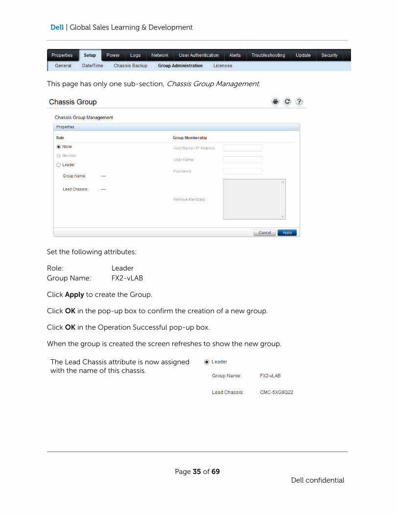
This page has only one sub-section, Chassis Group Management.
Set the following attributes:
Role: Leader
Group Name: FX2-vLAB
Click Apply to create the Group.
Click OK in the pop-up box to confirm the creation of a new group.
Click OK in the Operation Successful pop-up box.
When the group is created the screen refreshes to show the new group.
The Lead Chassis attribute is now assigned with the name of this chassis.

Dell | Global Sales Learning & Development
Page 36 of 69
Dell confidential
The left-hand-side panel will now be changed. A new section, Group: FX2-vLAB, will be created and the Chassis Overview will
change to
All the members will be greyed out.
The Group section now shows a mini status graphic for each of the members in the group.
The Group section has one tab, Properties, with two pages Group and Firmware Version.
The Group page shows the mini status graphic shown above and the Firmware Version page
shows a view of the BIOS/Firmware versions for all servers in the group.
7.5.2 Add a member to the group
In the Group Section select the lead Chassis. In the Setup tab select the Group
Administration page. In the Group Membership list enter the following details:
Host Name / IP Address: 192.168.0.140
User Name: root
Password: calvin
Dell | Global Sales Learning & Development
Page 37 of 69
Dell confidential
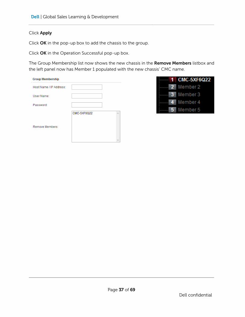
Click Apply
Click OK in the pop-up box to add the chassis to the group.
Click OK in the Operation Successful pop-up box.
The Group Membership list now shows the new chassis in the Remove Members listbox and
the left panel now has Member 1 populated with the new chassis’ CMC name.

Dell | Global Sales Learning & Development
Page 38 of 69
Dell confidential
The Properties tab of the Group section now shows a quick status of the two chassis in the
group.
Note the new member has a quick link to jump to the CMC management of that chassis.
7.5.3 Propagate Chassis Properties
Now that a group has been created the Group Administration page now has an additional
sub-section Chassis Properties Propagation
Dell | Global Sales Learning & Development
Page 39 of 69
Dell confidential
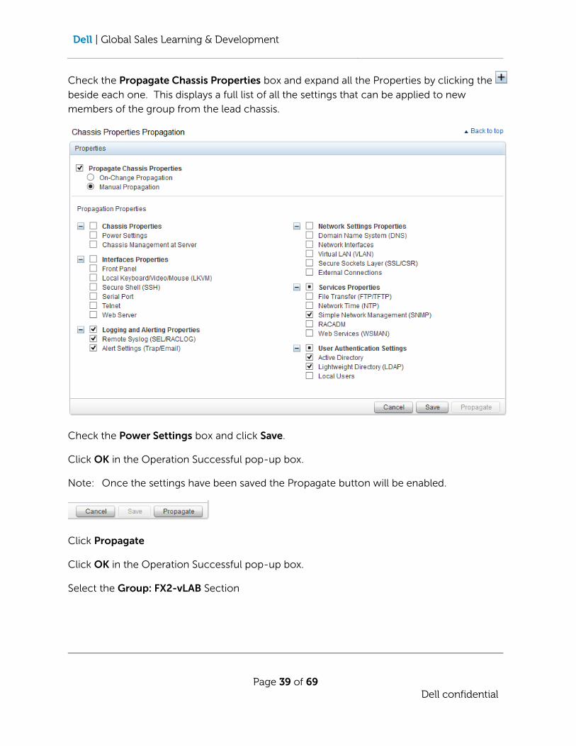
Check the Propagate Chassis Properties box and expand all the Properties by clicking the
beside each one. This displays a full list of all the settings that can be applied to new
members of the group from the lead chassis.
Check the Power Settings box and click Save.
Click OK in the Operation Successful pop-up box.
Note: Once the settings have been saved the Propagate button will be enabled.
Click Propagate
Click OK in the Operation Successful pop-up box.
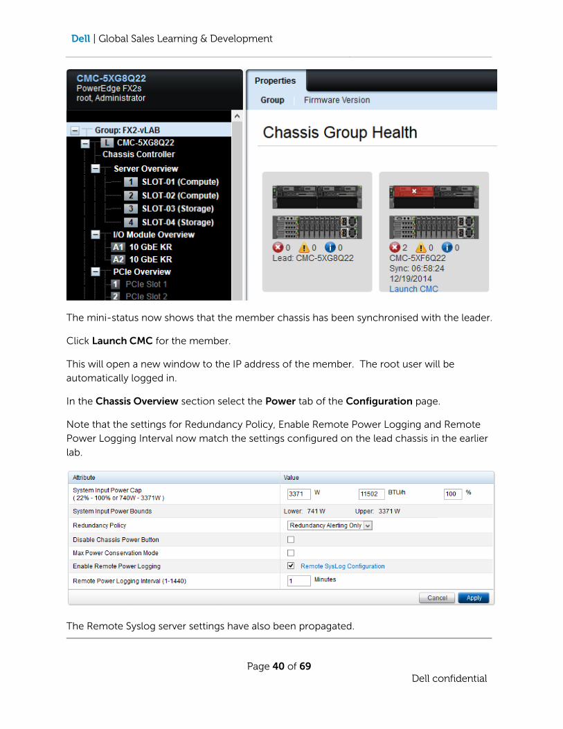
Select the Group: FX2-vLAB Section
Dell | Global Sales Learning & Development
Page 40 of 69
Dell confidential
The mini-status now shows that the member chassis has been synchronised with the leader.
Click Launch CMC for the member.
This will open a new window to the IP address of the member. The root user will be
automatically logged in.
In the Chassis Overview section select the Power tab of the Configuration page.
Note that the settings for Redundancy Policy, Enable Remote Power Logging and Remote
Power Logging Interval now match the settings configured on the lead chassis in the earlier
lab.
The Remote Syslog server settings have also been propagated.

Dell | Global Sales Learning & Development
Page 41 of 69
Dell confidential
7.5.4 Chassis Group Firmware
In the Group section of the Lead Chassis select the Firmware Version page.
This show a list of the chassis in the group and the health status and the BIOS/Firmware
versions of the selected chassis.
Select the Member chassis to view the details for that chassis.
Note that this is a view only. To update any of the versions follow the procedure outlined in
the previous lab.
Dell | Global Sales Learning & Development
Page 42 of 69
Dell confidential
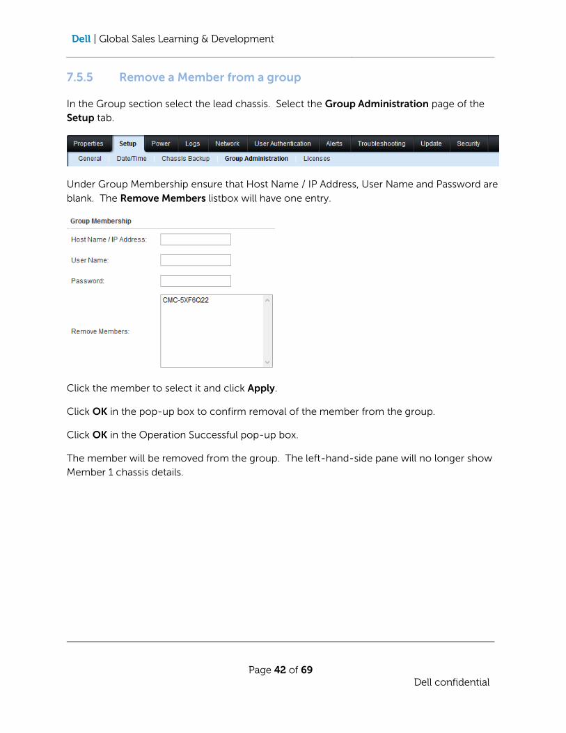
7.5.5 Remove a Member from a group
In the Group section select the lead chassis. Select the Group Administration page of the
Setup tab.
Under Group Membership ensure that Host Name / IP Address, User Name and Password are
blank. The Remove Members listbox will have one entry.
Click the member to select it and click Apply.
Click OK in the pop-up box to confirm removal of the member from the group.
Click OK in the Operation Successful pop-up box.
The member will be removed from the group. The left-hand-side pane will no longer show
Member 1 chassis details.
Dell | Global Sales Learning & Development
Page 43 of 69
Dell confidential
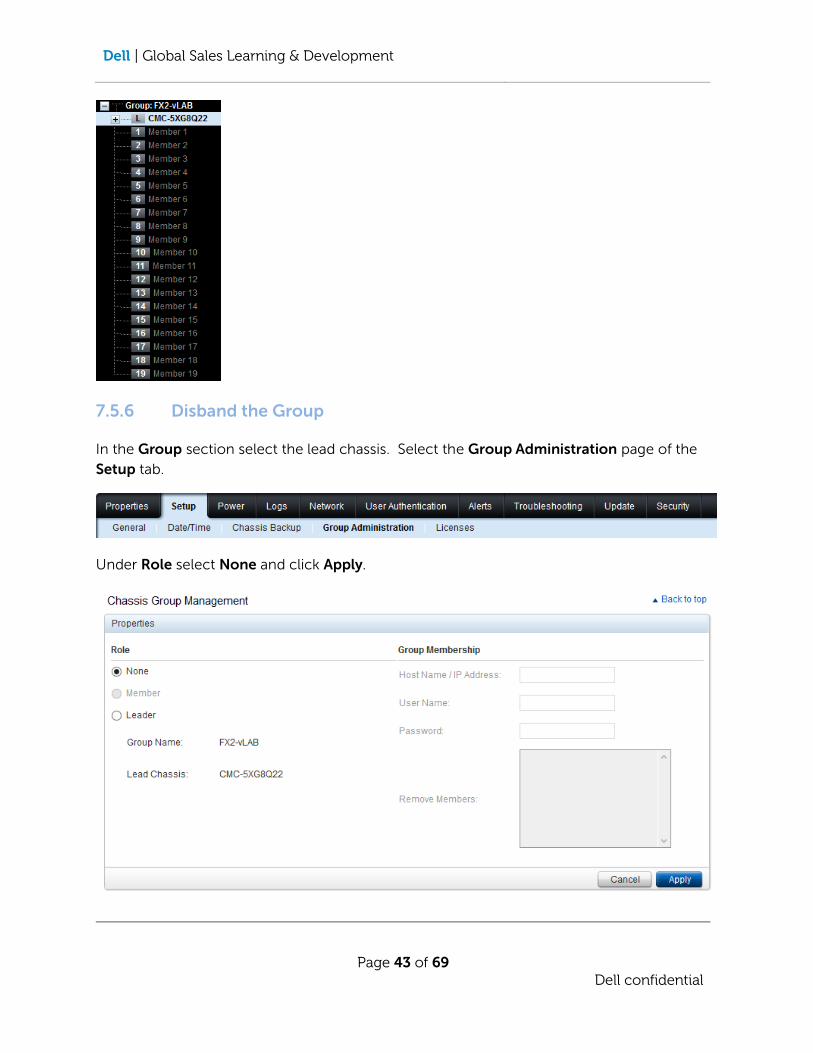
7.5.6 Disband the Group
In the Group section select the lead chassis. Select the Group Administration page of the
Setup tab.
Under Role select None and click Apply.

Dell | Global Sales Learning & Development
Page 44 of 69
Dell confidential
Click OK in the pop-up box to confirm disbanding the group.
Click OK in the Operation Successful pop-up box.
All references to the Group will be removed from the left-hand-side panel and the Chassis
Properties Propagation sub-section will be removed from the page.
8 LAB 8: Networking
8.1 Introduction
In this Lab you will be performing the following tasks:
Overview of the FX2 FN IOA
Configure IOA IP settings
Setup VLANs
Power control of the IOAs
8.2 Talking Points:
This lab covers the setup of IO Aggregators in an FX2. The IOA brings the ability to configure
end-point networking to the chassis administrator. Once a VLAN has been tagged from the
Top-Of-Rack switch that VLAN can be tagged, or untagged, to any of the sleds in the chassis.
This is the same as a virtualization administrator being able to add a virtual machine to Port
Group in VMware’s vCenter without requiring intervention from the network team.
8.3 Technical Selling Points:
There are five network options for the FX2. Two pass-through modules, 1Gb and 10Gb, and
three IOAs, the FN401s with four SFP+ external ports, the FN410T with four 10GbE copper
external ports and the FN2210s with two SFP+ 10GbE ports and two 4/8Gb fibre channel
ports. All IOAs have eight internal 10GbE ports. The IOA is a layer 2 switch and provides
East-West switching between sleds in the chassis. Up to 6 IOAs can be stacked or VLT’d.
8.4 Technical Objections and Query Handling
Question: Can the FN IOA be used as a router?
Answer: No. The FN IOA are layer 2 switch modules.
Question: Can the FN2210s be directly connected to a SAN?
Answer: No. The FN2210s operates in NPG (NPIV Proxy Gateway) mode and must
be connected to Fibre Channel fabric.

Dell | Global Sales Learning & Development
Page 45 of 69
Dell confidential
Question: Can the VLAN assignment of external ports on the FN IOA be managed via the CMC?
Answer: No. The CMC can be used to change the VLAN settings on internal ports
only. By default all the external ports are configured in a port-channel and
all VLANs are tagged on the port-channel. VLANs entering the chassis are
limited by the configuration of the Top-Of-Rack switch.
8.5 Lab 8: Networking with the FN IOA – [Step by Step]
8.5.1 Configure IP Settings
In the IO Module Overview section select the Deploy page on the Setup tab.
In the Network Settings section of Slot A1 change the following options:
Enable DHCP: (disabled)
IP Address: 192.168.0.138
Static Netmask: 255.255.255.0
Static Gateway: 192.168.0.1
Click Apply, then click OK on the message pop-up.
Dell | Global Sales Learning & Development
Page 46 of 69
Dell confidential
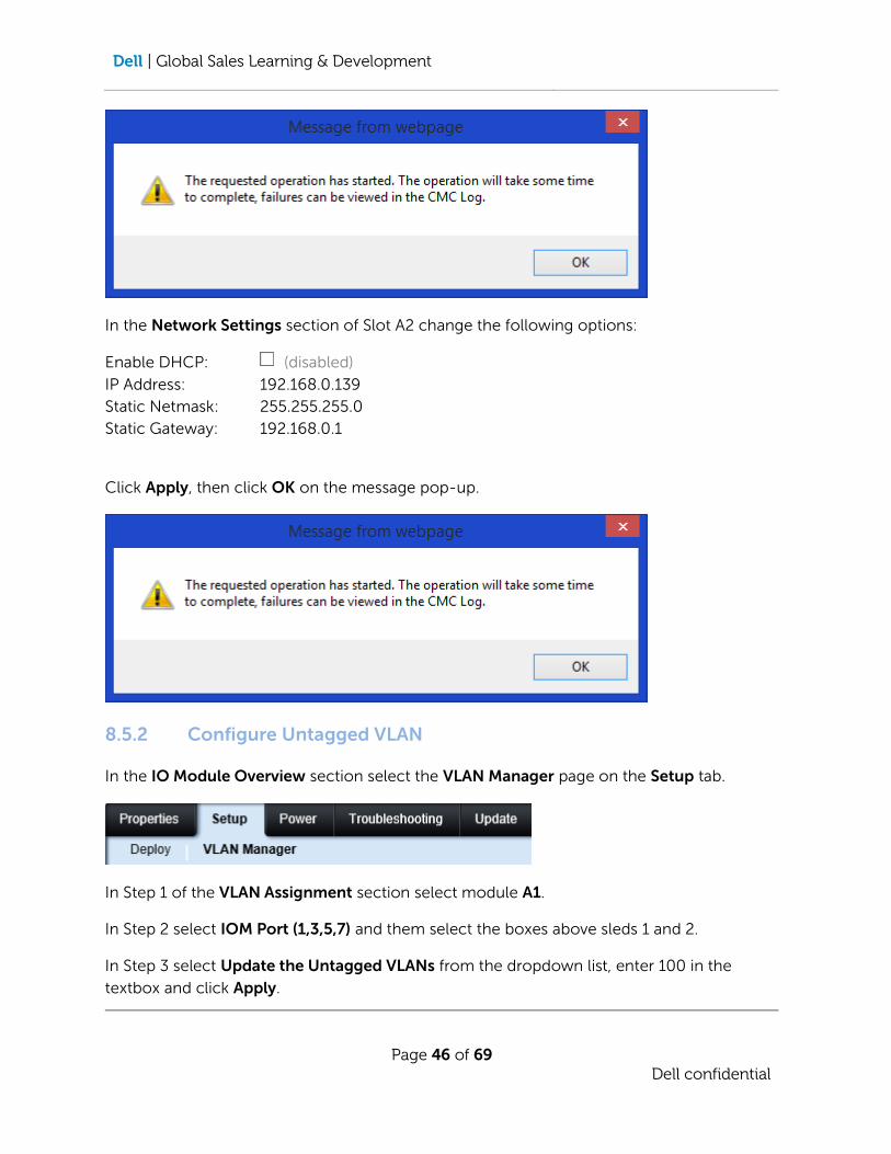
In the Network Settings section of Slot A2 change the following options:
Enable DHCP: (disabled)
IP Address: 192.168.0.139
Static Netmask: 255.255.255.0
Static Gateway: 192.168.0.1
Click Apply, then click OK on the message pop-up.
8.5.2 Configure Untagged VLAN
In the IO Module Overview section select the VLAN Manager page on the Setup tab.
In Step 1 of the VLAN Assignment section select module A1.
In Step 2 select IOM Port (1,3,5,7) and them select the boxes above sleds 1 and 2.
In Step 3 select Update the Untagged VLANs from the dropdown list, enter 100 in the
textbox and click Apply.

Dell | Global Sales Learning & Development
Page 47 of 69
Dell confidential
Click OK on the confirmation pop-up.
Dell | Global Sales Learning & Development
Page 48 of 69
Dell confidential
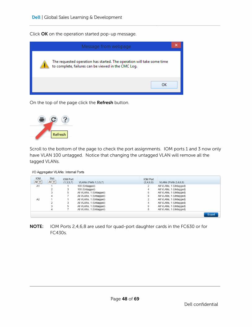
Click OK on the operation started pop-up message.
On the top of the page click the Refresh button.
Scroll to the bottom of the page to check the port assignments. IOM ports 1 and 3 now only
have VLAN 100 untagged. Notice that changing the untagged VLAN will remove all the
tagged VLANs.
NOTE: IOM Ports 2,4,6,8 are used for quad-port daughter cards in the FC630 or for
FC430s.
Dell | Global Sales Learning & Development
Page 49 of 69
Dell confidential
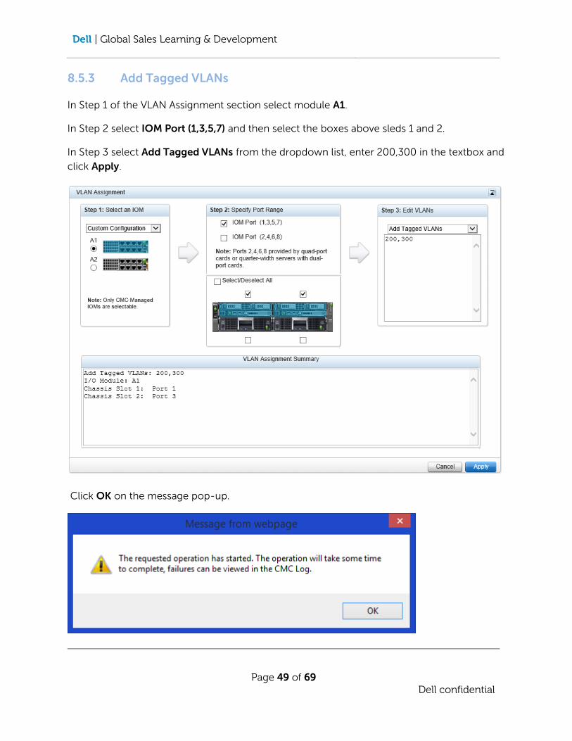
8.5.3 Add Tagged VLANs
In Step 1 of the VLAN Assignment section select module A1.
In Step 2 select IOM Port (1,3,5,7) and then select the boxes above sleds 1 and 2.
In Step 3 select Add Tagged VLANs from the dropdown list, enter 200,300 in the textbox and
click Apply.
Click OK on the message pop-up.

Dell | Global Sales Learning & Development
Page 50 of 69
Dell confidential
On the top of the page click the Refresh button.
Scroll to the bottom of the page to check the port assignments. IOM ports 1 and 3 now have
VLANs 200 and 300 tagged and VLAN 100 untagged. Note that adding VLANs to a port does
not remove existing tagged VLANs or change the untagged VLAN.

Dell | Global Sales Learning & Development
Page 51 of 69
Dell confidential
8.5.4 Remove Tagged VLANs
In Step 1 of the VLAN Assignment section select module A1.
In Step 2 select IOM Port (1,3,5,7) and then select the boxes above sleds 1 and 2.
In Step 3 select Remove VLANs from the dropdown list and enter 300 in the textbox and
click Apply.
Click OK on the confirmation pop-up.

Dell | Global Sales Learning & Development
Page 52 of 69
Dell confidential
Click OK on the operation started pop-up message.
On the top of the page click the Refresh button.
Scroll to the bottom of the page to check the port assignments. IOM ports 1 and 3 now only
have VLAN 200 tagged and VLAN 100 untagged.

Dell | Global Sales Learning & Development
Page 53 of 69
Dell confidential
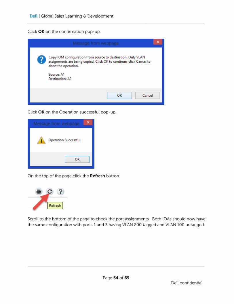
8.5.5 Copy VLAN Settings Between FN IOAs
In Step 1 of the VLAN Assignment section select module A2. Then select Copy A1
Configuration from the dropdown list and click Apply.
NOTE: Steps 2 and 3 are disabled when copying a configuration.
Dell | Global Sales Learning & Development
Page 54 of 69
Dell confidential
Click OK on the confirmation pop-up.
Click OK on the Operation successful pop-up.
On the top of the page click the Refresh button.
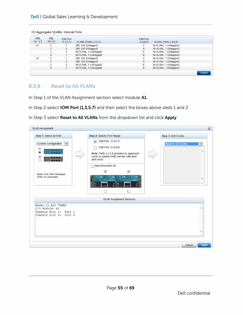
Scroll to the bottom of the page to check the port assignments. Both IOAs should now have
the same configuration with ports 1 and 3 having VLAN 200 tagged and VLAN 100 untagged.
Dell | Global Sales Learning & Development
Page 55 of 69
Dell confidential
8.5.6 Reset to All VLANs
In Step 1 of the VLAN Assignment section select module A1.
In Step 2 select IOM Port (1,3,5,7) and then select the boxes above sleds 1 and 2.
In Step 3 select Reset to All VLANs from the dropdown list and click Apply.
Dell | Global Sales Learning & Development
Page 56 of 69
Dell confidential
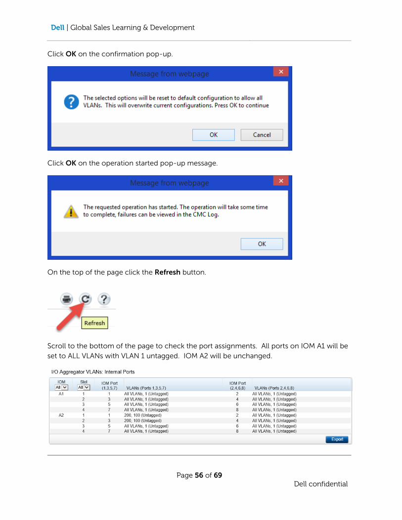
Click OK on the confirmation pop-up.
Click OK on the operation started pop-up message.
On the top of the page click the Refresh button.
Scroll to the bottom of the page to check the port assignments. All ports on IOM A1 will be
set to ALL VLANs with VLAN 1 untagged. IOM A2 will be unchanged.
Dell | Global Sales Learning & Development
Page 57 of 69
Dell confidential
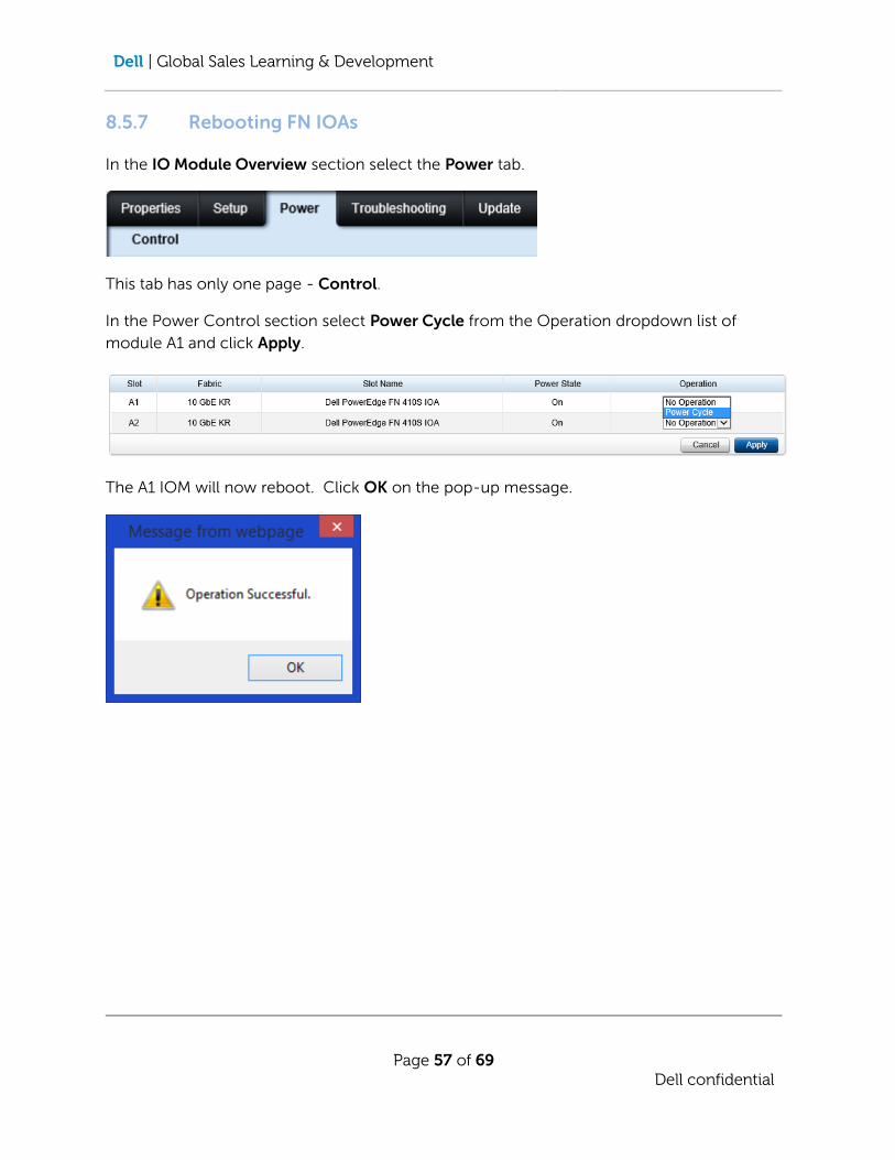
8.5.7 Rebooting FN IOAs
In the IO Module Overview section select the Power tab.
This tab has only one page - Control.
In the Power Control section select Power Cycle from the Operation dropdown list of
module A1 and click Apply.
The A1 IOM will now reboot. Click OK on the pop-up message.

Dell | Global Sales Learning & Development
Page 58 of 69
Dell confidential
8.5.8 Resetting FN IOAs
In the IO Module Overview section select the Deploy page on the Setup tab.
Click Reset to Factory Defaults for Slot A2.
Click OK in the confirmation pop-up box.

Dell | Global Sales Learning & Development
Page 59 of 69
Dell confidential
Click OK on the operation started pop-up message.
NOTE: When the IOA resets and restarts, the network settings will revert to defaults with a
DHCP address on the IOA. In production the IP address will need to be reset to a
static value. Also, all ports on IOM A2 will be reset to ALL VLANs tagged with VLAN
1 untagged.
8.5.8 Checking Port Status
In the I/O Module Overview section select module A1 10 GbE KR.
In the Properties tab select the Status page.
In the I/O Module Internal Port Settings section it can be seen that the FC630s in slots 1 and
2 have 10Gbps connections on IOM ports 1 and 3.

Dell | Global Sales Learning & Development
Page 60 of 69
Dell confidential
In the I/O Module External Port Settings section it can be seen that there are two 10Gbps
connections to the Top-Of-Rack switch on IOM ports 9 and 10.
8.5.9 IOM Firmware Update
In the I/O Module Overview section select the Update tab.
This tab has only one page – IOM Firmware Update
In the IOM Firmware section check the Update checkbox for Slot A1. The Browse button will
now be activated. Click Browse and select FTOS-XL-9.8.0.0.bin from the Downloads folder.
Click Apply Firmware Update and then click OK in the confirmation pop-up.
Dell | Global Sales Learning & Development
Page 61 of 69
Dell confidential
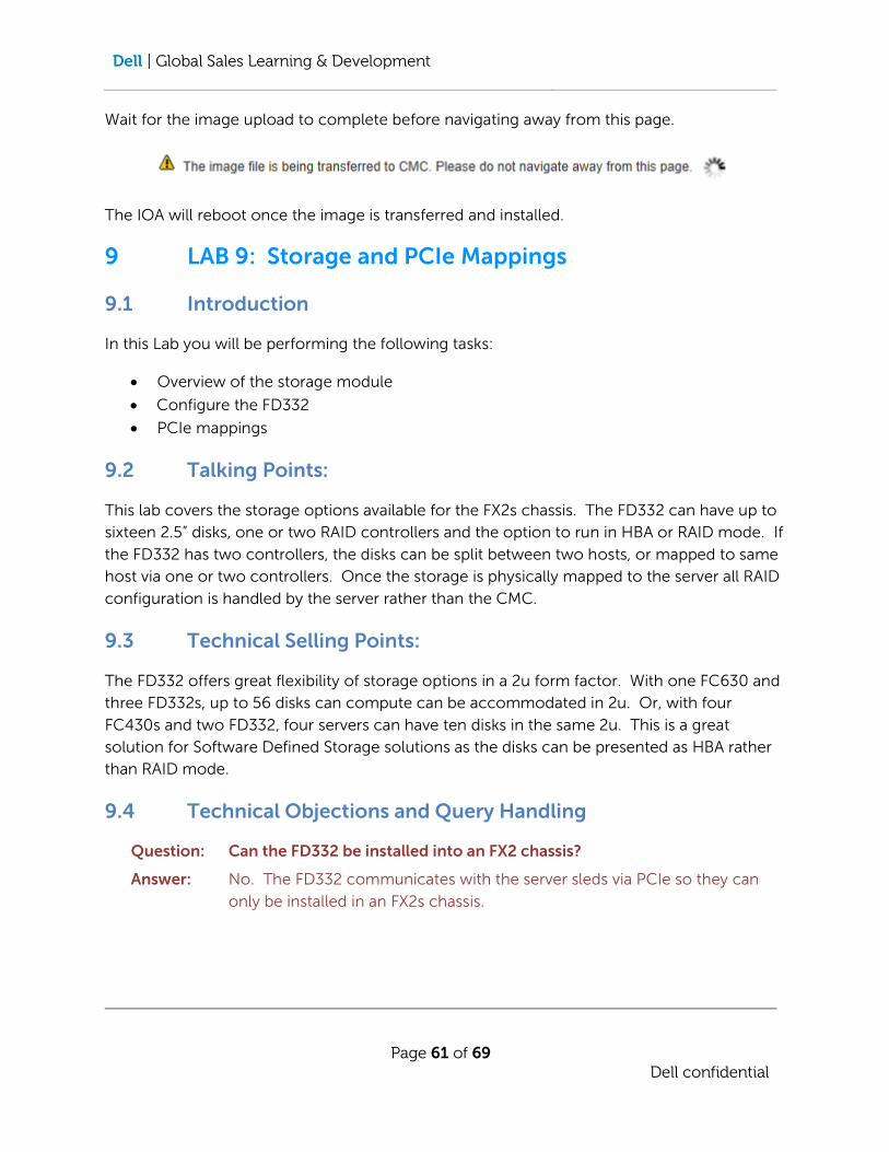
Wait for the image upload to complete before navigating away from this page.
The IOA will reboot once the image is transferred and installed.
9 LAB 9: Storage and PCIe Mappings
9.1 Introduction
In this Lab you will be performing the following tasks:
Overview of the storage module
Configure the FD332
PCIe mappings
9.2 Talking Points:
This lab covers the storage options available for the FX2s chassis. The FD332 can have up to
sixteen 2.5” disks, one or two RAID controllers and the option to run in HBA or RAID mode. If
the FD332 has two controllers, the disks can be split between two hosts, or mapped to same
host via one or two controllers. Once the storage is physically mapped to the server all RAID
configuration is handled by the server rather than the CMC.
9.3 Technical Selling Points:
The FD332 offers great flexibility of storage options in a 2u form factor. With one FC630 and
three FD332s, up to 56 disks can compute can be accommodated in 2u. Or, with four
FC430s and two FD332, four servers can have ten disks in the same 2u. This is a great
solution for Software Defined Storage solutions as the disks can be presented as HBA rather
than RAID mode.
9.4 Technical Objections and Query Handling
Question: Can the FD332 be installed into an FX2 chassis?
Answer: No. The FD332 communicates with the server sleds via PCIe so they can
only be installed in an FX2s chassis.

Dell | Global Sales Learning & Development
Page 62 of 69
Dell confidential
Question: Can the FD332 share storage between multiple servers?
Answer: No. The disks in the FD332 are physically connected to a controller. The
controller is then mapped to a server and all drives on that controller pass to
the server. While there can be two controllers in an FD332, each manages
its own disks and there is no sharing between them.
Question: Can the PCIe slots be assigned via the CMC like the VRTX?
Answer: No. The PCIe slots in the FX2s are hard mapped and cannot be changed.
9.5 Lab 9: Storage and PCIe Mappings – [Step by Step]
9.5.1 Dual Controller FD332
In the Server Overview section select Slot-03 (Storage).
Dell | Global Sales Learning & Development
Page 63 of 69
Dell confidential
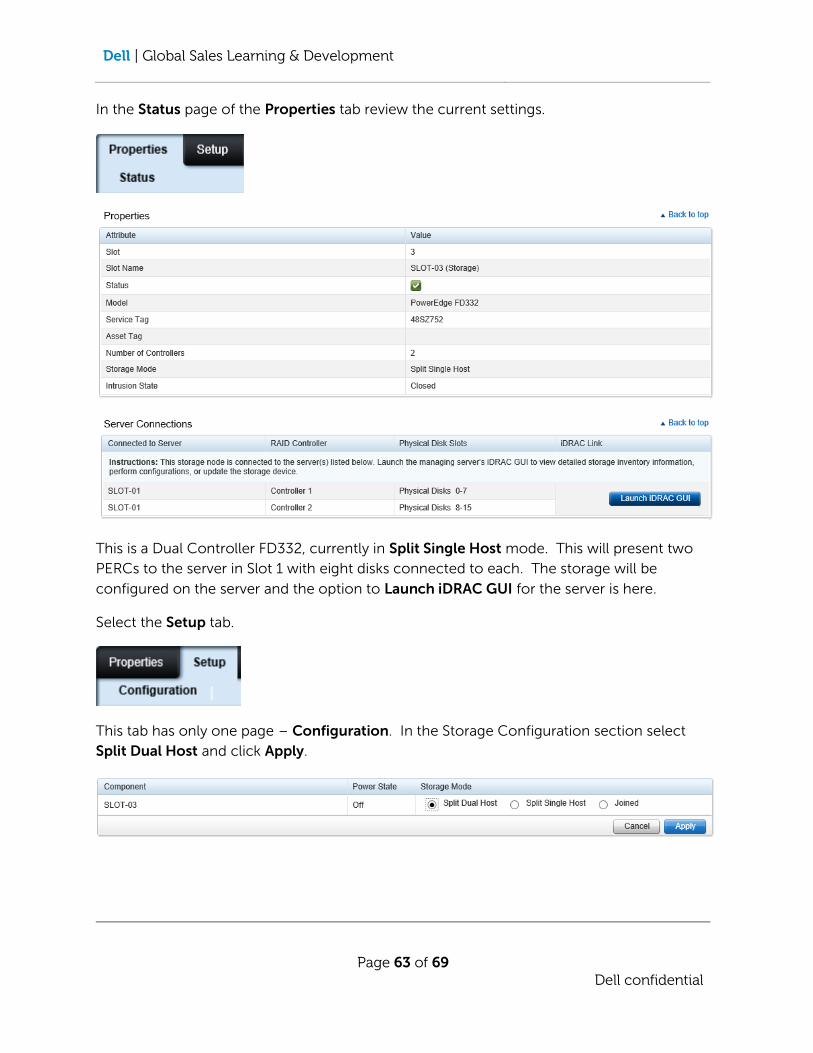
In the Status page of the Properties tab review the current settings.
This is a Dual Controller FD332, currently in Split Single Host mode. This will present two
PERCs to the server in Slot 1 with eight disks connected to each. The storage will be
configured on the server and the option to Launch iDRAC GUI for the server is here.
Select the Setup tab.
This tab has only one page – Configuration. In the Storage Configuration section select
Split Dual Host and click Apply.

Dell | Global Sales Learning & Development
Page 64 of 69
Dell confidential
Click OK in the confirmation pop-up box.
Click OK on the operation successful pop-up message.
Dell | Global Sales Learning & Development
Page 65 of 69
Dell confidential
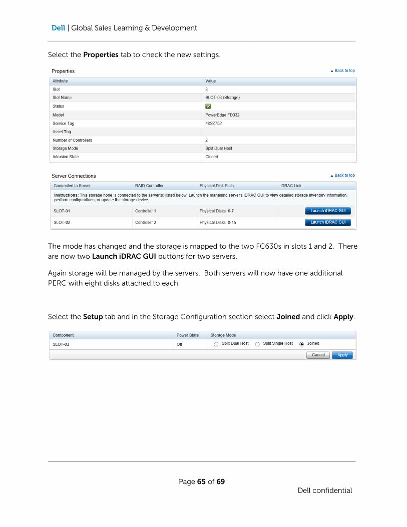
Select the Properties tab to check the new settings.
The mode has changed and the storage is mapped to the two FC630s in slots 1 and 2. There
are now two Launch iDRAC GUI buttons for two servers.
Again storage will be managed by the servers. Both servers will now have one additional
PERC with eight disks attached to each.
Select the Setup tab and in the Storage Configuration section select Joined and click Apply.

Dell | Global Sales Learning & Development
Page 66 of 69
Dell confidential
Click OK in the confirmation pop-up box.
Click OK on the operation successful pop-up message.

Dell | Global Sales Learning & Development
Page 67 of 69
Dell confidential
Select the Properties tab to check the new settings.
The mode has changed and the storage is mapped to the FC630 in slot 1. There is now one
Launch iDRAC GUI button for the server.
Once again storage will be managed by the server which will now have one additional PERC
with sixteen disks attached to it.
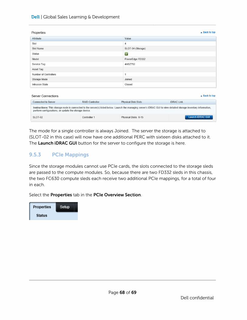
9.5.2 Single Controller FD332
In the Server Overview section select Slot-04 (Storage).
In the Status page of the Properties tab review the current settings.
NOTE: There is no Setup tab for the single controller module.
Dell | Global Sales Learning & Development
Page 68 of 69
Dell confidential
The mode for a single controller is always Joined. The server the storage is attached to
(SLOT-02 in this case) will now have one additional PERC with sixteen disks attached to it.
The Launch iDRAC GUI button for the server to configure the storage is here.
9.5.3 PCIe Mappings
Since the storage modules cannot use PCIe cards, the slots connected to the storage sleds
are passed to the compute modules. So, because there are two FD332 sleds in this chassis,
the two FC630 compute sleds each receive two additional PCIe mappings, for a total of four
in each.
Select the Properties tab in the PCIe Overview Section.

Dell | Global Sales Learning & Development
Page 69 of 69
Dell confidential
There is only page on this tab – Status.
Here we see that compute slot 1 has PCIe slots 5, 6, 7 and 8 mapped and compute slot 2 has
PCIe slots 1, 2, 3 and 4 mapped.
NOTE: These are hard mapped and cannot be changed within the CMC.
Even if there are no storage sleds installed in the chassis, it is still possible to map all the slots
from the lower slots to the upper slots. This will result in double the number of PCIe slots
available to the upper compute slots and no PCIe slots available to the lower compute slots.
Select the Setup tab, then select Enable PCIe Slot Reassignment and click Apply.
Click OK on the operation successful pop-up.


![[1996] [Riloff] Automatically Generating Extraction Patterns From Untagged Text - AAAI96-155](https://static.fdocuments.net/doc/165x107/577d34b71a28ab3a6b8eace3/1996-riloff-automatically-generating-extraction-patterns-from-untagged.jpg)