Fundamental LC-MS Orbitrap Mass Analyzers · Linear quadrupole ion traps have some advantages over...
30
i Wherever you see this symbol, it is important to access the on-line course as there is interactive material that cannot be fully shown in this reference manual. Mass Spectrometry Fundamental LC-MS Orbitrap Mass Analyzers
Transcript of Fundamental LC-MS Orbitrap Mass Analyzers · Linear quadrupole ion traps have some advantages over...
i Wherever you see this symbol, it is important to access the on-line course as there is interactive material that cannot be fully shown in this reference manual.
Mass Spectrometry
Fundamental LC-MS
Orbitrap Mass Analyzers

Aims and Objectives
Aims and Objectives
Aims To introduce the mass analyser invented by Makarov and is called orbitrap
To describe the ion separation process in the orbitrap mass analyser
Objectives At the end of this Section you should be able to:
Explain the advantages and disadvantages of using the orbitrap mass analyser
List the main components of the orbitrap mass analyser
Explain how to perform the coupling between an orbitrap mass analyser and a continuous ion source
Understand the principles of image current detection
Differentiate the different operative modes (FT and MSI) common to orbitrap mass analysers and when to use each one of them
Recognise the importance of Fourier Transformation (FT) in signal processing
Recognise linear traps as very efficient ways of ion storage

© Crawford Scientific www.chromacademy.com
2
Content Introduction 3 Overview 4 Analyzer Anatomy 5 Equations of Motion 6 Continuous Ion Sources 7 Quadrupole Mass Analyzer 9 Linear Quadrupole Ion Traps 10 Curved Multipoles 11 Curved Linear Traps 12 Image Current Detection 14 Ion Injection 15 Fourier Transform (FT) Mode 17 Fourier Transform 18 Mass Selective Instability (MSI) Mode 19 Multiply Charged Ions 20 Tune and Calibration 20 High Molecular Weight Application 22 Low Molecular Weight Application 24 Comparison with Other Analysers 25 References 26

© Crawford Scientific www.chromacademy.com
3
Introduction Ion trapping techniques are important tools in mass spectrometry. However, traditional ion trap mass analysers have disadvantages in either performance (insufficient mass accuracy, limited linear range, reduced charge capacity, etc.) or high complexity and cost. The orbitrap,[1,2,3] a new type of mass analyser, has drawn attention due to its analytical performance in terms of resolution, mass accuracy, space charge capacity and linear dynamic range, relatively small size and cost.
Invented by Makarov, the orbitrap mass analyzer is based on the Kingdom trap which uses a wire stretched along the axis of an outer cylinder enclosing the trapping volume. Orbitrap mass analysers operate using a pulsed technique and as such the task of coupling to any external continuous ion source was initially regarded as a serious problem. The main objective of this module is to introduce the orbitrap as a new type of mass analyser capable of performing dynamic trapping.
i
© Crawford Scientific www.chromacademy.com
4
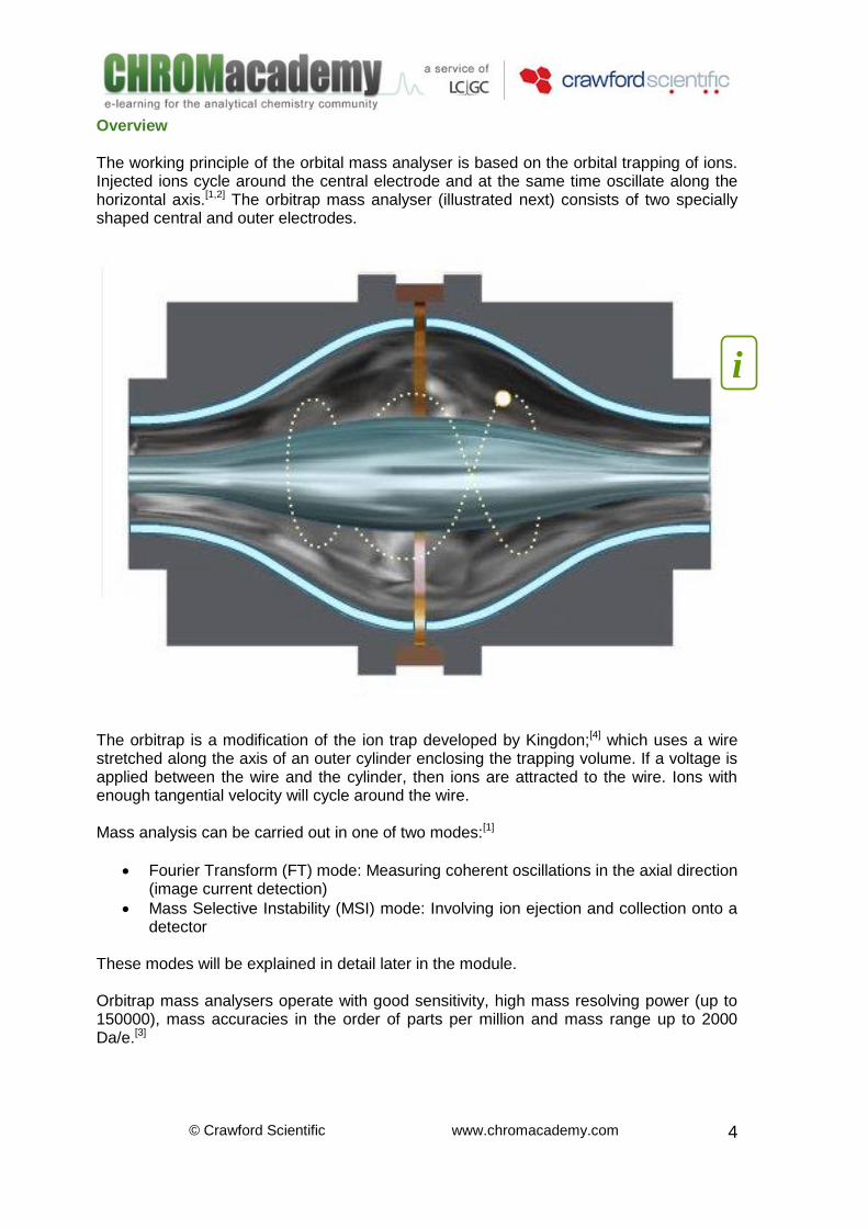
Overview The working principle of the orbital mass analyser is based on the orbital trapping of ions. Injected ions cycle around the central electrode and at the same time oscillate along the horizontal axis.[1,2] The orbitrap mass analyser (illustrated next) consists of two specially shaped central and outer electrodes.
The orbitrap is a modification of the ion trap developed by Kingdon;[4] which uses a wire stretched along the axis of an outer cylinder enclosing the trapping volume. If a voltage is applied between the wire and the cylinder, then ions are attracted to the wire. Ions with enough tangential velocity will cycle around the wire. Mass analysis can be carried out in one of two modes:[1]
Fourier Transform (FT) mode: Measuring coherent oscillations in the axial direction (image current detection)
Mass Selective Instability (MSI) mode: Involving ion ejection and collection onto a detector
These modes will be explained in detail later in the module. Orbitrap mass analysers operate with good sensitivity, high mass resolving power (up to 150000), mass accuracies in the order of parts per million and mass range up to 2000 Da/e.[3]
i

© Crawford Scientific www.chromacademy.com
5
Analyzer Anatomy The orbitrap mass analyser consists of an outer barrel like electrode and a central spindle like electrode along the axial axis. Both electrodes are connected to independent voltage supplies.[1,2] The outer electrode is split into two parts: one for ion excitation and the other for detection. The working principles of this electrode are explained at the end of this module. The space between the internal and external electrodes forms the measurement chamber which is linked to a vacuum pump system to provide high vacuum conditions (approximately 10-8 torr or lower). If good signal and high resolution are required, then ions of each mass must have a coherent movement, this is achieved by injecting them in a very short bursts (or ‘packets’). Ion introduction can be efficiently performed after modification of the electric field at the injection port. This can be achieved by using a field compressor which is a small portion of the outer electrode.
i
© Crawford Scientific www.chromacademy.com
6
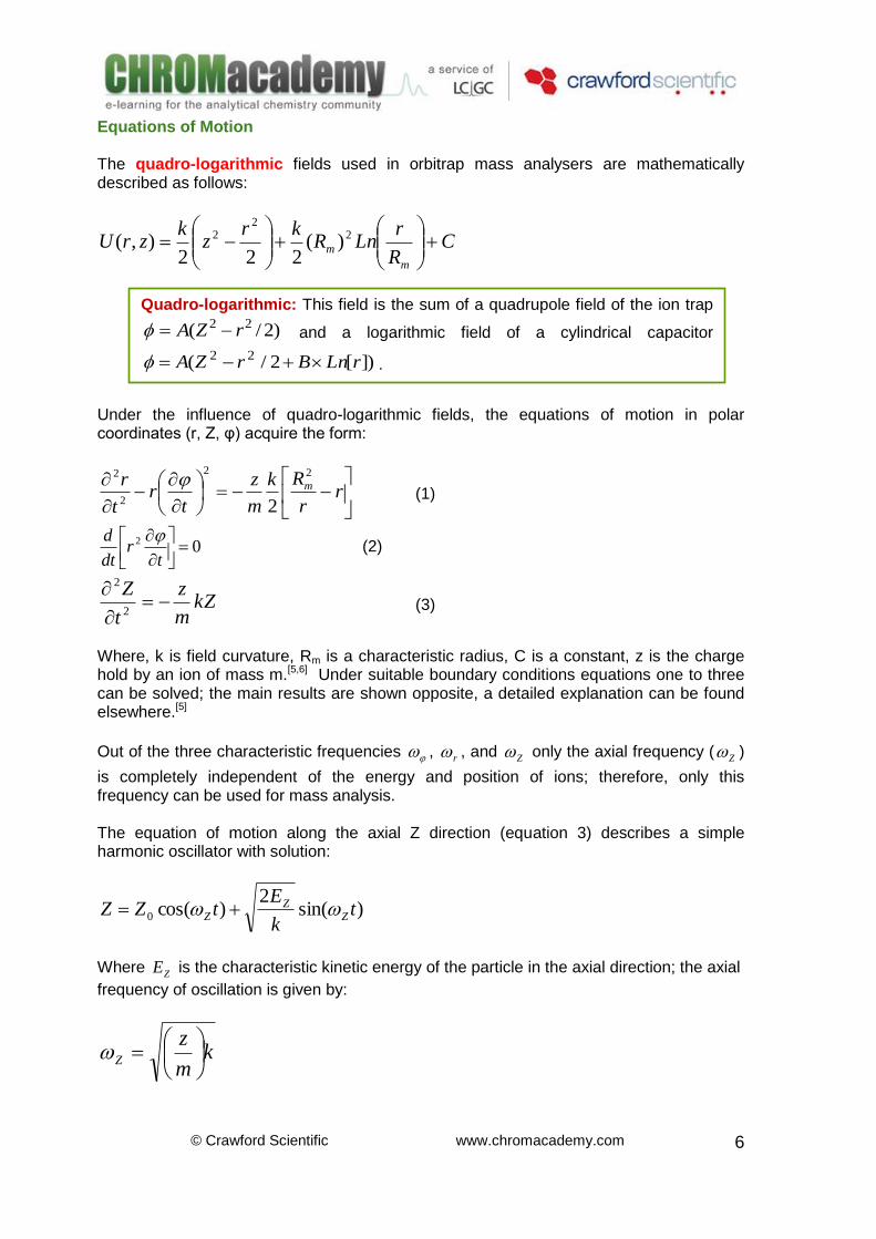
Equations of Motion The quadro-logarithmic fields used in orbitrap mass analysers are mathematically described as follows:
CR
rLnR
krz
kzrU
m
m
2
22 )(
222),(
Under the influence of quadro-logarithmic fields, the equations of motion in polar coordinates (r, Z, φ) acquire the form:
r
r
Rk
m
z
tr
t
r m
22
2
2
2
(1)
02
tr
dt
d (2)
kZm
z
t
Z
2
2
(3)
Where, k is field curvature, Rm is a characteristic radius, C is a constant, z is the charge hold by an ion of mass m.[5,6] Under suitable boundary conditions equations one to three can be solved; the main results are shown opposite, a detailed explanation can be found elsewhere.[5]
Out of the three characteristic frequencies , r , and Z only the axial frequency ( Z )
is completely independent of the energy and position of ions; therefore, only this frequency can be used for mass analysis. The equation of motion along the axial Z direction (equation 3) describes a simple harmonic oscillator with solution:
)sin(2
)cos(0 tk
EtZZ Z
ZZ
Where ZE is the characteristic kinetic energy of the particle in the axial direction; the axial
frequency of oscillation is given by:
km
zZ
Quadro-logarithmic: This field is the sum of a quadrupole field of the ion trap
)2/( 22 rZA and a logarithmic field of a cylindrical capacitor
])[2/( 22 rLnBrZA .
© Crawford Scientific www.chromacademy.com
7
The equations of motion along the radial (r) and rotational (φ) directions can be approximately solved (the final results are not shown) and it can be demonstrated that frequencies in these directions depend upon energy and position of the ions or in other words, these two frequencies are not used for mass analysis.
Simple Harmonic Oscillator.
The motion of a simple harmonic oscillator is governed by:
xdt
xd 2
2
2
The solution of this equation is of the form:
)cos()sin()( tBtAtx
Where A, B and are constants, x is the coordinate of displacement in the time domain
(t). Continuous Ion Sources Although orbitrap mass analyzers operate in a pulsed fashion, they can be coupled to continuous ion sources. Ion storage devices had made possible this coupling. Prior to injection into the orbitrap, ions are transported from the source at high pressure to the storage device (usually a linear ion trap) at low pressure. The first two quadrupoles shown opposite (guide and transport) are used to bring the ions through several stages of differential pumping. Instrument performance can be increased by using an external collision quadrupole ion trap for storage between injections. This device not only permits bursts of ions from a continuous source (like ESI) but also allows control of the number of ions introduced into the orbitrap (reducing space-charge effects). A set of transfer lenses between the storage quadrupole and the entrance of the orbitrap is also included. The objective of this set of lenses is to accelerate and focus the ion beam into the entrance channel of the analyzer.[3] The process of ion introduction from a continuous source is shown opposite.
i

© Crawford Scientific www.chromacademy.com
8
i
© Crawford Scientific www.chromacademy.com
9
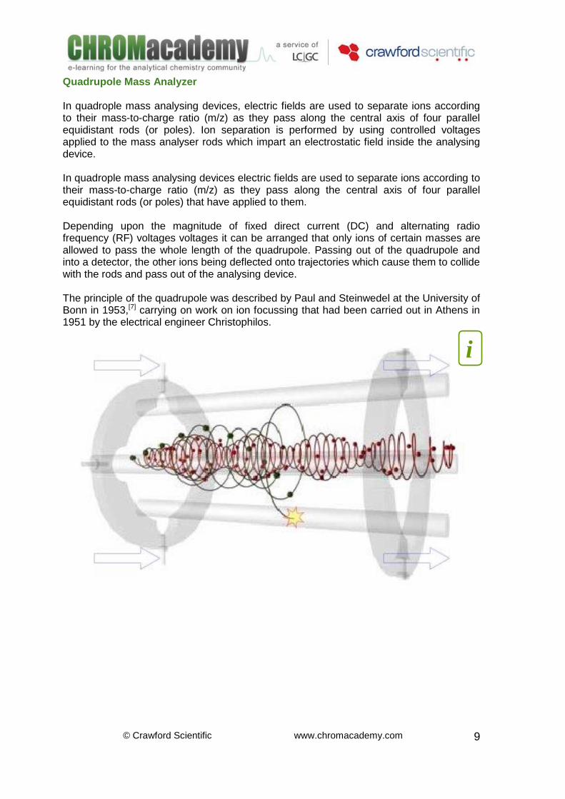
Quadrupole Mass Analyzer In quadrople mass analysing devices, electric fields are used to separate ions according to their mass-to-charge ratio (m/z) as they pass along the central axis of four parallel equidistant rods (or poles). Ion separation is performed by using controlled voltages applied to the mass analyser rods which impart an electrostatic field inside the analysing device. In quadrople mass analysing devices electric fields are used to separate ions according to their mass-to-charge ratio (m/z) as they pass along the central axis of four parallel equidistant rods (or poles) that have applied to them. Depending upon the magnitude of fixed direct current (DC) and alternating radio frequency (RF) voltages voltages it can be arranged that only ions of certain masses are allowed to pass the whole length of the quadrupole. Passing out of the quadrupole and into a detector, the other ions being deflected onto trajectories which cause them to collide with the rods and pass out of the analysing device. The principle of the quadrupole was described by Paul and Steinwedel at the University of Bonn in 1953,[7] carrying on work on ion focussing that had been carried out in Athens in 1951 by the electrical engineer Christophilos.
i
© Crawford Scientific www.chromacademy.com
10
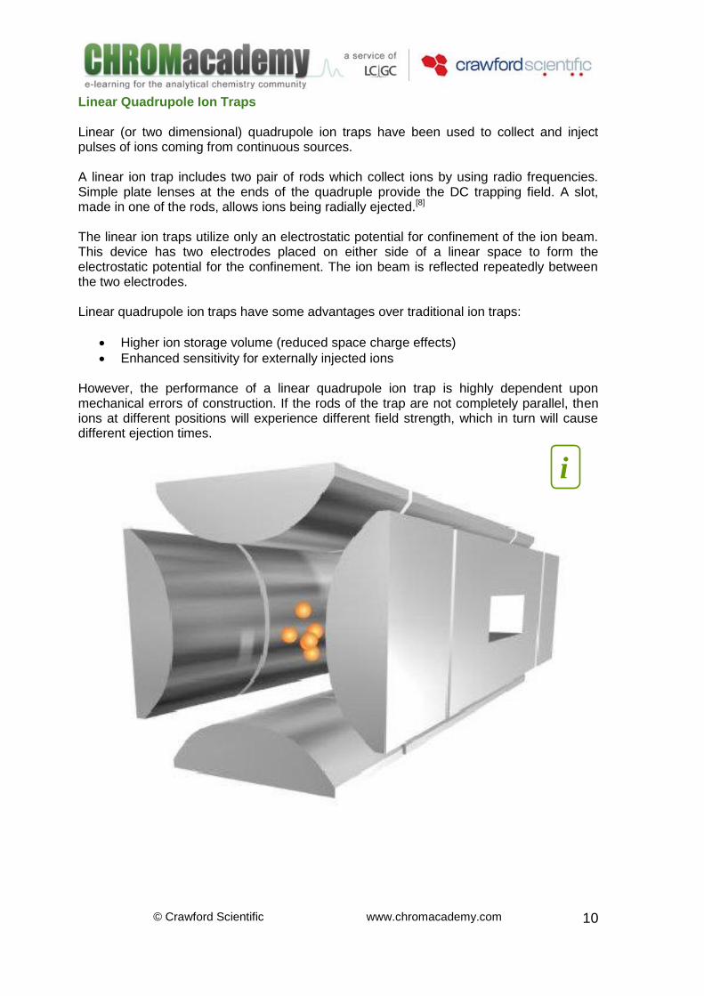
Linear Quadrupole Ion Traps Linear (or two dimensional) quadrupole ion traps have been used to collect and inject pulses of ions coming from continuous sources. A linear ion trap includes two pair of rods which collect ions by using radio frequencies. Simple plate lenses at the ends of the quadruple provide the DC trapping field. A slot, made in one of the rods, allows ions being radially ejected.[8] The linear ion traps utilize only an electrostatic potential for confinement of the ion beam. This device has two electrodes placed on either side of a linear space to form the electrostatic potential for the confinement. The ion beam is reflected repeatedly between the two electrodes. Linear quadrupole ion traps have some advantages over traditional ion traps:
Higher ion storage volume (reduced space charge effects)
Enhanced sensitivity for externally injected ions However, the performance of a linear quadrupole ion trap is highly dependent upon mechanical errors of construction. If the rods of the trap are not completely parallel, then ions at different positions will experience different field strength, which in turn will cause different ejection times.
i
© Crawford Scientific www.chromacademy.com
11
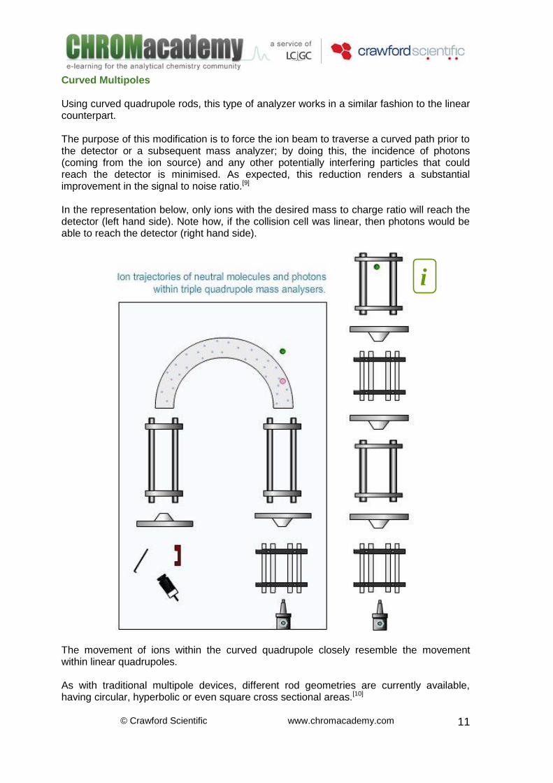
Curved Multipoles Using curved quadrupole rods, this type of analyzer works in a similar fashion to the linear counterpart. The purpose of this modification is to force the ion beam to traverse a curved path prior to the detector or a subsequent mass analyzer; by doing this, the incidence of photons (coming from the ion source) and any other potentially interfering particles that could reach the detector is minimised. As expected, this reduction renders a substantial improvement in the signal to noise ratio.[9] In the representation below, only ions with the desired mass to charge ratio will reach the detector (left hand side). Note how, if the collision cell was linear, then photons would be able to reach the detector (right hand side).
The movement of ions within the curved quadrupole closely resemble the movement within linear quadrupoles. As with traditional multipole devices, different rod geometries are currently available, having circular, hyperbolic or even square cross sectional areas.[10]
i
© Crawford Scientific www.chromacademy.com
12
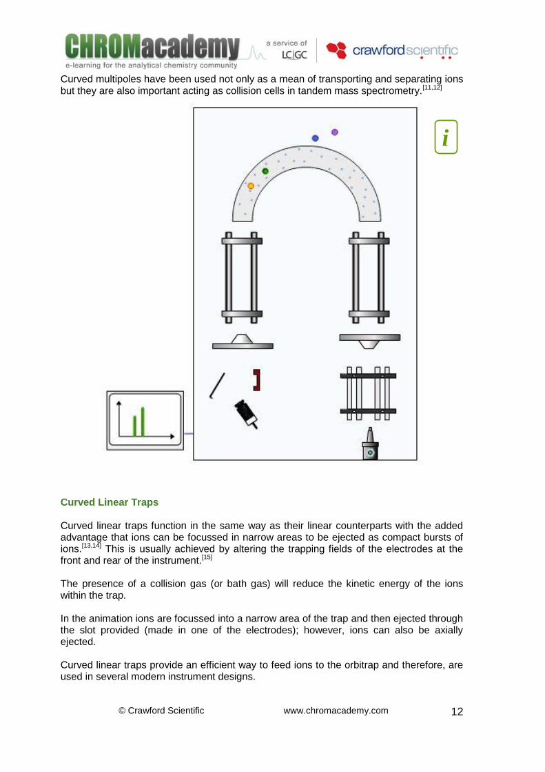
Curved multipoles have been used not only as a mean of transporting and separating ions but they are also important acting as collision cells in tandem mass spectrometry.[11,12]
Curved Linear Traps Curved linear traps function in the same way as their linear counterparts with the added advantage that ions can be focussed in narrow areas to be ejected as compact bursts of ions.[13,14] This is usually achieved by altering the trapping fields of the electrodes at the front and rear of the instrument.[15] The presence of a collision gas (or bath gas) will reduce the kinetic energy of the ions within the trap. In the animation ions are focussed into a narrow area of the trap and then ejected through the slot provided (made in one of the electrodes); however, ions can also be axially ejected. Curved linear traps provide an efficient way to feed ions to the orbitrap and therefore, are used in several modern instrument designs.
i

© Crawford Scientific www.chromacademy.com
13
i

© Crawford Scientific www.chromacademy.com
14
Image Current Detection Trapped ions can be detected in situ by measuring the image current they produce. The main advantage of this technique is the ability to re-measuring ion populations.[16] The image current detection technique has been successfully implemented not only in conventional ion traps but in high mass resolution analysers (FT-ICR and orbitrap).[16,17,18,19] Ions populating the analyser describe different trajectories (according to the analyser itself). A coherent excitation (DC pulse) is imposed to the ions in such a way that ions of the same mass to charge ratio move coherently. Following the DC excitation, the image current is measured on the detector electrodes. The trajectories described for the ions through the quadrupole are complex and cannot be described in a simple way; however, after a coherent excitation is imposed (usually a pulse variation in the electrostatic field between rods) in such a way that populations of ions will perform coherent oscillations between two opposite rods. The movement of ions between the rods will induce an electric current that can be measured. As expected, the intensity of the current is proportional to the number of ions. The principle of image current detection is further explained below.
Ion detection is followed by a fast Fourier Transform algorithm to convert the recorded time domain signal into a mass/charge spectrum.
i

© Crawford Scientific www.chromacademy.com
15
Ion Injection In order to achieve high resolution with the orbitrap, then ions of each mass to charge ratio must have a coherent movement and this is achieved by injecting them in a very short time (or in bursts). The curved linear ion trap is one of the most efficient ways of injecting ions to the orbitrap.[1,2,3,5,15]
Slow injection
Unlike linear ion traps, the curved linear ion trap allows ions to be injected into the orbitrap at a position offset from its equator and in fact, by doing this, ions will perform coherent axial oscillations almost immediately after injection without the need for any additional excitation; this type of ion injection is known as “fast injection”.[16,17]
i

© Crawford Scientific www.chromacademy.com
16
Fast injection
When ions are injected at an equatorial position, then ion oscillation is achieved by imposing an additional excitation; this type of ion injection is known as “slow injection”.[1] In order to eliminate gas carryover from the trap (linear or curved), the ion beam is usually deflected by a set of transfer ions.
i

© Crawford Scientific www.chromacademy.com
17
Fourier Transform (FT) Mode Ions within the orbitrap have three different frequencies of oscillation: axial, radial and rotational.[1] In order to detect frequencies of oscillations, the motion of ions needs to be coherent. Coherence in the axial direction can be induced by different ways:[2,5,24]
Feeding bursts of ions in the orbitrap at a position different to its equator, these packets of ions will start coherent axial oscillations without the need for any additional excitation
If a voltage pulse is applied to one part of the outer electrode, then ions (which already populate the analyser in a disc area) will accommodate at certain axial position; when the pulse is over, ions will coherently oscillate with harmonic motion
One or both parts of the outer electrode are then used to detect trapped ions by measuring their image current (which is generated as the ions axially oscillate back and forward). The Fourier Transform of the signal can be used to produce the required mass spectrum. This mode of detection yields the highest mass resolution that the orbitrap can achieve. The Fourier Transform mode measures coherent oscillations in the axial direction (image current detection).
Principle of image current detection (FT mode) in orbitrap mass analysers.
Ion movement within the orbitrap comprises rotations around the central electrode with axial oscillations; however, only the axial oscillations are important for ion detection.
i

© Crawford Scientific www.chromacademy.com
18
Fourier Transform The Fourier Transform (FT) is a mathematical operation that transforms one function in the time domain to a second function in the frequency domain. If a function is to be intergrated then its Fourier Transform function (also integrable) can be found.[22,23] The FT theory is based on the idea that any integrable function can be expressed as a summation of sines and cosines of different frequencies. In signal processing the domain of the original function is usually time; the domain of the new function is usually the frequency domain. Working in the frequency domain offers some advantages including:
Collect information in ways that sometimes facilitate signal analysis (for example periodic noise can be easily identified and removed)
By using FT is easy to go backwards and forwards from the time to the frequency domain
Although discrete FT expressions can be used to calculate the FT of a function (see equations opposite), more efficient methods are required. Fast Fourier Transform (FFT) algorithms are based on discrete FT expressions and are widely implemented in most modern instruments.[22] There are many different ways in which FFT algorithms are implemented; however, programming skills are required and therefore, we will not discuss this topic any further. If f(x) is a continuous integrable function of a real variable x, then its Fourier Transform is defined by:
dxexfuF
uix2)()(
Given F(u), the original function f(x) can be easily recovered by using the inverse Fourier Transform, which is defined by:
dueuFxf
uix2)()(
The previous expressions are used with mathematic functions; however, their use in signal processing is limited and discrete expressions are used instead:
1
0
/2)(
1)(
N
x
Nuixexf
NuF
1
0
/2)()(
N
x
NuixeuFxf

© Crawford Scientific www.chromacademy.com
19
Mass Selective Instability (MSI) Mode The second mode of mass detection available with orbitrap mass analysers involves ejection of the ions and collection on a detector (as is used with conventional mass analysers like quadrupole, time of flight, magnetic sector, etc.). Although the principal analysis method of the orbitrap is the FT mode (allowing the highest mass resolution the equipment can achieve), there are some instances in which the MSI mode should be used, for example ions with certain mass to charge ratio can be stored for MS/MS analysis, or high intensity signals from unwanted compounds can be ejected to improve dynamic range.[1] Application of the appropriate frequency will results in excitation of oscillations and finally ion ejection from the measurement chamber. A convenient means of detection of the ejected ions is collision with a conversion dynode in the outer electrode, which generates secondary electrons which can be accelerated to a detector. MSI can be achieved in one out of two ways: Parametric resonance: the voltage applied to the electrodes is varied sinusoidally with time Resonance excitation: If the sinusoidally oscillations are applied to half of the outer electrode (excitation electrode).
Ions exiting the orbitrap collide with a dynode generating secondary electrons, these electrons are then multiplied, collected and detected. Whether “parametric resonance” or “resonance excitation” is the best MSI mode for high resolution depends on the application in which it is to be used.
i

© Crawford Scientific www.chromacademy.com
20
Multiply Charged Ions Due to their high resolving power, orbitrap mass analysers can handle the MS analysis of heavy and multiply charged molecules (which is the case in many different areas such as in proteomics). Although other analysers can be used, the orbitrap possess combined advantages of performance and price not possessed by any of its counterparts.[25,26]
Orbitrap ESI-MS spectrum of horse heart myoglobin protein (16.9 kDa).
Tune and Calibration The tune and calibration parameters of modern instruments can be easily reset to their original values. This of overriding importance when starting your system after a complete shutdown. Orbitrap mass analysers require periodic re-calibration (according to the manufacturer’s instructions). The ion mode operation (positive or negative) as well as the ionisation type (ESI, MALDI, etc) will determine the correct calibration molecules. To tune and calibrate your analyser, infuse the correct calibration solution and register its MS spectrum. Some molecule that can be used for calibration under ESI positive ion mode conditions include:[27,28]
Caffeine
MRFA peptide
Ultramark
Bradikinin 1-9

© Crawford Scientific www.chromacademy.com
21
Selected molecules currently used for calibration under ESI negative ion mode conditions include:
MRFA peptide
Ultramark
SDS
Sodium taurocholate As expected, calibration kits are currently available.[29]

© Crawford Scientific www.chromacademy.com
22
High Molecular Weight Application Proteomics, the large scale study of proteins, is one of the most active and demanding research fronts of MS. Due to its high performance, the orbitrap mass analyser is well suited for protein structure elucidation. In the application opposite,[30] a pure immunoglobulin gamma sample was infused into an orbitrap mass analyser and then its ESI(+)-MS spectrum was recorded.
ESI(+)-MS spectrum of human immunoglobulin gamma (147250 Da) on an Orbitrap
analyzer
Immunoglobulin Gamma (IgG): are tetra-peptides molecules of around 150kDa; acting as an antibody, IgG is the most abundant immunoglobulin.
i

© Crawford Scientific www.chromacademy.com
23
A basic deconvolution algorithm was used to find its molecular weight. The strategy considers that if two adjacent peaks in the spectrum (m1 and m2) are from the same molecule, then:[31,32]
111 /)( nHnMm
222 /)( nHnMm
If the charge state of both peaks (n1 and n2) differs only by the addition of a single proton:
121 nn
Then:
12
21
mm
Hmn
)( 11 HmnM
Where M is the molecular weight of the analyte and H is the molecular weight of hydrogen.
The average molecular weight found with the orbitrap (147252.3 Da) is in good agreement with the theoretical value of 147250 Da, with an error of only 0.00159%.

© Crawford Scientific www.chromacademy.com
24
Low Molecular Weight Application Lipidomics, the large scale study of pathways and networks of lipids in biological systems, is a very important research topic in Mass Spectrometry. Due to its high resolving power, the orbitrap mass analyser can be used to differentiate molecules with identical nominal mass (isobaric molecules). In the application below,[33] a mixture of phosphatidylethanolamines was infused into an orbitrap mass analyser and the ESI(-)-MS spectrum recorded. The high mass region of the spectrum reveals the presence of two isobaric species.
i

© Crawford Scientific www.chromacademy.com
25
The price to pay for high resolution is time. Note that the higher the resolution, the longer the time required for performing one single scan (spectral experiment). As expected, longer analysis time will permit more data points to be gathered. The interactive example shown (please refer to the online material), illustrates how resolution can be used to differentiate isobaric molecules. Please bear in mind that:[34,35,36,37]
The spectrum corresponds to a sample that contains only two different isobaric analytes
Labels “A” and “B” correspond to anionic pseudomolecular ions coming from the deprotonation of each analyte within the sample and are of the form [M-1]-
Labels “A+1” and “B+1” correspond to the isotopic form of each pseudomolecular ion previously defined (mainly due to the presence of 13C on each molecule)
Comparison with Other Analysers The table below reports typical figures of merit for selected mass analysers.[38,39,40]
Please bear in mind that the resolving power depends upon the mass to charge ratio and scan speed at which the instrument is operating. It is also important to note that sensitivity depends upon the ionisation efficiency.

© Crawford Scientific www.chromacademy.com
26
References
1. Alexander Makarov. “Mass Spectrometer” United States Patent No US 5886346. March 23, 1999. 2. Alexander Makarov and Mark E. Hardman. “Mass Spectrometry Method and Apparatus” United States Patent No US 6998609 B2. February 14, 2006. 3. Qizhi Hu, Robert J. Noll, Hongyan Li, Alexander Makarov, Mark Hardmanc and R. Graham Cooks. “The Orbitrap: a new mass spectrometer.” Journal of Mass Spectrometry. 2005; 40: 430–443. 4. K. H. Kingdon. “A Method for the Neutralization of Electron Space Charge by Positive Ionization at Very Low Gas Pressures.” Physical Review 21, 408–418 (1923) 5. Mark Hardman and Alexander A. Makarov. “Interfacing the Orbitrap Mass Analyzer to an Electrospray Ion Source.” Analytical Chemistry 2003, 75, 1699-1705. 6. Alexander Makarov. “Electrostatic Axially Harmonic Orbital Trapping: A High-Performance Technique of Mass Analysis.” Analytical Chemistry 2000, 72, 1156-1162. 7. W. Paul & H. Steinwedel. “Zeitschrift für Naturforschung.” 8A; (1953), p448. 8. Jae C. Schwartz, Viatcheslav V. Kovtoun and Michael W. Senko. “Two-Dimensional Quadrupole Ion Trap Operated as a Mass Spectrometer” United States Patent No US 7034294 B2. April 25, 2006. 9. Richard H. Perry, R. Graham Cooks, and Robert J. Noll. “Orbitrap Mass Spectrometry: Instrumentation, Ion Motion and Applications” Mass Spectrometry Reviews, 2008, 27, 661– 699 10. LTQ Series Hardware Manual. Thermo Scientific. 97055-97072 Revision A April 2009 11. Gökhan Baykut. “Introduction of Ions from Ion Sources Into Mass Spectrometers” United States Patent Number US 5825026. October 20, 1998. 12. Syka, John Edward Philip. “Mass Spectrometer” European Patent Application Number 87301870.9. March 4, 1987. 13. Alexander Makarov, Eduard Denisov, Alexander Kholomeev, Wilko Balschun, Oliver Lange, Kerstin Strupat, and Stevan Horning. “Performance Evaluation of a Hybrid Linear Ion Trap/Orbitrap Mass Spectrometer” Analytical Chemistry 2006, 78, 2113-2120 14. Alexander Makarov, Eduard Denisov, Oliver Lange, and Stevan Horning. “Dynamic Range of Mass Accuracy in LTQ Orbitrap Hybrid Mass Spectrometer” Journal American Society for Mass Spectrometry. 2006, 17, 977–982 15. Alexander Makarov. “Theory and Practice of the Orbitrap Mass Analyzer” Proceedings of the 54th ASMS Conference on Mass Spectrometry and Allied Topics. 2006. 16. Ethan R. Badman, Garth E. Patterson, J. Mitchell Wells, Robert E. Santini and R. Graham Cooks. “Differential Non-destructive Image Current Detection in a Fourier

© Crawford Scientific www.chromacademy.com
27
Transform Quadrupole Ion Trap” Journal of Mass Spectrometry, Volume 34, Issue 8 (p 889-894) 17. Michael Senko. “Linear Quadrupole Mass Spectrometer” United States Patent No US 6403955 B1. June 11, 2002. 18. Syka, John E. P, Fies, Jr., William J. “Fourtier transform quadrupole mass spectrometer and method” United States Patent No US 4755670. July 5, 1988. 19. Mario Nappi, Vladimir Frankevich, Manish Soni, R. Graham Cooks. “Characteristics of a broad-band Fourier transform ion trap mass spectrometer” International Journal of Mass Spectrometry 177 (1998) 91–104 20. Alexander Makarov, Mark E. Hardman, Jae C. Schwartz, Michael W. Senko. “Mass Spectrometry Method and Apparatus” United States Patent Number US 6872938. March 29, 2005. 21. Alexander Alekseevich Makarov. “Mass Spectrometer” United States Patent Number US 7759638 B2. July 20, 2010. 22. William H. Press, Saul A. Teukolsky, William T. Vetterling and Brian P. Flannery. “Numerical Recipes in C++ The Art of Scientific Computing” Second Edition Chapters 12 – 13. Cambridge University Press. The Edinburgh Building, Cambridge CB2 2RU, UK 2002 23. K.F. Riley, M.P. Hobson and S. J. Bence. “Mathematical Methods for Physics and Engineering” Chapter 13. K. F. Riley, M. P. Hobson and S. J. Bence 2006 24. Alexander Makarov, Mark E. Hardman, Jae C. Schwartz, Michael W. Senko. “Mass Spectrometry Method and Apparatus” United States Patent Number US 6995364 B2. Feb 7, 2006. 25. Alexander Makarov and Eduard Denisov. “Dynamics of Ions of Intact Proteins in the Orbitrap Mass Analyzer” Journal American Society Mass Spectrometry 2009, 20, 1486–1495 26. Yang Luo, Tuo Li, Fang Yu, Tal Kramer, and Ileana M. Cristea. “Resolving the Composition of Protein Complexes Using a MALDI LTQ Orbitrap” Journal American Society Mass Spectrometry 2010, 21, 34–46 27 John C. L. Erve, Ming Gu, Yongdong Wang, William DeMaio, and Rasmy E. Talaat. “Spectral Accuracy of Molecular Ions in an LTQ/Orbitrap Mass Spectrometer and Implications for Elemental Composition Determination” Journal of American Society for Mass Spectrometry 2009, 20, 2058–2069 28 Mikhail V. Gorshkov, David M. Good, Yaroslav Lyutvinskiy, Hongqian Yang, Roman A. Zubarev. “Calibration Function for the Orbitrap FTMS Accounting for the Space Charge Effect” Journal of American Society for Mass Spectrometry 2010, Article in Press. 29. Kerstin Strupat, Viatcheslav Kovtoun, Huy Bui, Rosa Viner, George Stafford, and Stevan Horning. “MALDI Produced Ions Inspected with a Linear Ion Trap-Orbitrap Hybrid Mass Analyzer” Journal of American Society for Mass Spectrometry 2009, 20, 1451–1463 30. Pavel V. Bondarenko, Tonya P. Second, Vlad Zabrouskov, Alexander A. Makarov, and Zhongqi Zhang. “Mass Measurement and Top-Down HPLC/MS Analysis of Intact Monoclonal Antibodies on a Hybrid Linear Quadrupole Ion Trap–Orbitrap Mass Spectrometer” Journal of American Society for Mass Spectrometry 2009, 20, 1415–1424 31. “Introduction to MS Proteomic Research” from the MS Channel of CHROMacademy 32. Susan R. Mikkelsen, Eduardo Cortón. “Bioanalytical Chemistry” Copyright © 2004 by John Wiley and Sons. Pp 295-320 33. Thomas Moehring, Michaela Scigelova, Christer S. Ejsing, Dominik Schwudke, Andrej Shevchenko. “Essential Lipidomics Experiments using the LTQ Orbitrap Hybrid Mass Spectrometer” Thermo Electron Corporation 2006. Application Note 367. 34. “General Interpretation Strategies” from the MS Channel of CHROMacademy 35. “Electrospray Ionisation Theory” from the MS Channel of CHROMacademy 36. James Barker. “Mass Spectrometry” John Wiley and Sons 1999, 117-147.

© Crawford Scientific www.chromacademy.com
28
37. E. De Hoffmann, J. Charette, and V. Stroobant. “Mass Spectrometry –Principles and Applications.” John Wiley and Sons 1996, 39-48. 38. “Mass Analysers” from the MS Channel of CHROMacademy 39. Michael S. Bereman, Matthew M. Lyndon, R. Brent Dixon and David C. Muddiman. “Mass Measurement Accuracy Comparisons Between a Double-Focusing Magnetic Sector and a Time-of-Flight Mass Analyzer” Rapid Communications in Mass Spectrometry. 2008; 22: 1563–1566 40. Martin Krauss, Heinz Singer, Juliane Hollender. “LC–High Resolution MS in Environmental Analysis: from Target Screening to the Identification of Unknowns” Analytical and Bioanalytical Chemistry (2010) 397:943–951