Functional Safety of Machines and Systems - Siemens · Functional Safety of Machines and Systems...
25
Safety Integrated Functional Safety of Machines and Systems Easy Implementation of the European Machinery Directive www.siemens.com/safety-integrated EN ISO 13849-1 EN 62061
Transcript of Functional Safety of Machines and Systems - Siemens · Functional Safety of Machines and Systems...
Safety Integrated
Functional Safety of Machines and Systems
Easy Implementation of the European Machinery Directive
www.siemens.com/safety-integrated
EN ISO 13849-1
EN 62061

As a partner for all safety requirements, we do not only support
you with the respective safety-related products and systems, but
also consistently provide you with the most current know-how on
international standards and regulations. Machine manufacturers
and plant managers are offered a comprehensive training portfolio
as well as services for the entire lifecycle of safety-related systems
and machines.
New Standards Support Mechanical Engineers
Contents
Basic safety requirements in the production industry 4
Basic standards for the development of control functions 5
Step by step:Development and realization of safety control systems 6
Step 1: Strategy for risk minimization 8
Step 2: Risk evaluation 9
Step 3: Structure of the safety function and determination of the safety integrity 11
Step 4: Validation on the basis of the safety plan 17
Benefits all along the line: safety from a single source 18
Appendix: Standard B10 values 18
Glossary 19
Product portfolio 20
Global standards, far-ranging directives
2
To keep the residual risk in machine con-struction within tolerable limits, a com-prehensive risk assessment and, if re-quired, risk reduction are essential. Risk assessment provides, on the one hand, the gradual optimization of machine safety, and on the other ”proof“ in case of dam-age. The corresponding documentation describes the assessment principles and the resulting measures in order to mini-mize hazard. This documentation also lays the foundation for safe operation of a machine. At the same time, the industrial safety regulations require the machine operator to comprehensively train his staff on safe operation of a machine. If the operator combines individual machines into a system, effects machine modifica-tions or expands machine functions, he himself acts as a mechanical engineer.
Compliance with the machinery directive can be ensured in different ways: within the scope of a machine acceptance per-formed by an authorized test body, by meeting the requirements of harmonized standards – or by providing a proof of safety, which is connected with increased test and documentation expenditures. In any case, the CE marking with a respec-tive proof of safety visually proves compli-ance with the machinery directive. The CE marking is a binding requirement of the EU framework directive for industrial safety.
Avoiding accidents, preventing harmful consequences
Compared to the physical and psycholo-gical consequences of machine or system accidents for humans, mechanical damage is more tolerable – even though machine failures or production downtimes cause substantial fi nancial loss. In worst case sce-narios, however, the question of guilt has to be resolved within the scope of a post-incident examination. If it is revealed that not all relevant directives were complied with, high claims for damages may result. This might also have a negative impact on the corporate image – with far-reaching consequences. If, however, it can be prov-en that all relevant standards were com-plied with, it is assumable that the require-ments of the corresponding directives are also met (presumption of conformity).
This brochure will show you how to always be on the safe side with your machine.
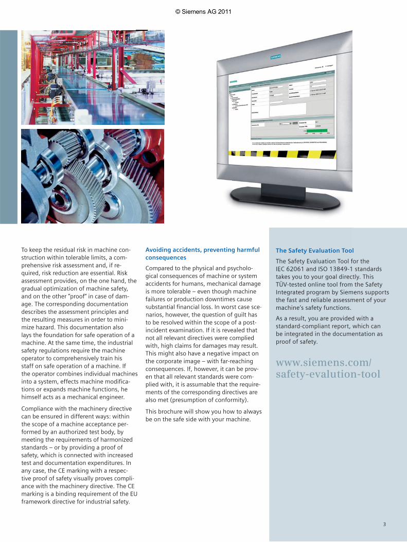
The Safety Evaluation Tool
The Safety Evaluation Tool for the IEC 62061 and ISO 13849-1 standards takes you to your goal directly. This TÜV-tested online tool from the Safety Integrated program by Siemens supports the fast and reliable assessment of your machine’s safety functions.
As a result, you are provided with a standard-compliant report, which can be integrated in the documentation as proof of safety.
www.siemens.com/safety-evalution-tool
e
Avoiding accidents, preventing harmful consequences
Compared to the physical and psycholo-gical consequences of machine or system accidents for humans, mechanical damage is more tolerable – even though machinefailures or production downtimes cause substantial fi nancial loss. In worst case sce-narios, however, the question of guilt has to be resolved within the scope of a post
The Safety Evaluation Too
The Safety Evaluation Tool fIEC 62061 and ISO 13849-1takes you to your goal direcTÜV-tested online tool fromIntegrated program by Siemthe fast and reliable assessmmachine’s safety functions.
As a result, you are provided
3

With the introduction of the uniform European Single Market, national standards and regulations affecting the technical realization of machines were consistently harmonized:
p Definition of basic safety requirements, which address, on the one hand, machine manufacturers in terms of the free movement of goods (Article 95) and, on the other hand, machine operators in terms of industrial safety (Article 137).
p As a consequence, the contents of the machinery directive, as a European Single Market directive, had to be transposed into national law by the individual member states. In Germany, for example, the equipment safety law (GSG) regulates the European safety requirements.
To ensure compliance with a directive, it is recommended to apply the harmonized European standards, which then confers the so-called “presumption of conformity” and provides both manufacturers and operators with legal certainty concerning compliance with national regulations such as the EC directive.
With the CE marking, the manufacturer of a machine documents the compliance with all applicable directives and regulations in the free movement of goods. As the European directives are globally approved, the CE marking is also useful for exports to EEA countries.
The following explanations are provided for mechanical engineers or machine operators who modify their machines in a way which affects safety.
Basic Safety Requirements in the Production Industry
Target: Protection of humans, machinesand the environment
Result: CE marking as proof of a ”safe machine“
Safety requirements
Article 95 EC Treaty (free movement of goods)
Article 137 EC Treaty (industrial safety)
e. g. machines
Low-voltage directive
(2006/95/EC)
Machinery directive
(2006/42/EC)
Harmonized European standards
Manufacturer
”Industrial safety“ framework directive (89/391/EEC)
Separate direc-tive ”Use of oper-ating equipment“
(89/655/EC)
National laws
User
4
Safety requires protection against various hazards. Such hazards can be eliminated as follows:
p Design on the basis of risk- minimizing principles – and risk evaluation of the machine (EN ISO 12100-1, EN ISO 14121-1)p Technical protective measures, e. g. by using safety-related control
systems (functional safety in acc. with EN 62061 or EN ISO 13849-1)
p Electrical safety (EN 60204-1)
The following section deals with functional safety, which refers to safety aspects of a machine or system depending on the correct functioning of control devices and guards.Two applicable standards are:
p EN 62061:2005 – the European sector standard of the basic standard IEC 61508
p EN ISO 13849-1:2006 – the revised successor standard of EN 954-1, as the latter does not sufficiently account for the different categories
Basic Standards for the Developmentof Control Functions
Target: Compliance with all applicable safety requirements by sufficient risk minimization – pursuing the objective of seizing export opportunities without taking liability risks.
Result: Realization of risk-minimizing protective measures by applying harmonized standards – thus, compliance with the safety requirements of the machinery directive on the basis of the ”presumption of conformity“.
Design and risk evaluation of the machine
EN ISO 12100 Safety of machines Basic terms, general principles
Safety of machines Risk assessment, part 1: principlesEN ISO 14121-1
Functional and safety-relevant requirements for safety-related control systems
Development and realization of safety-related controls
EN 62061:2005Safety of machines Functional safety of safety-related electrical, electronic and programmable
electronic control systems
Any architecturesSafety Integrity Level (SIL)SIL 1, SIL 2, SIL 3
EN ISO 13849-1:2006Safety of machinesSafety-related components of controls,
part 1: general principles
Successor standard of EN 954-1:1996 Transition period until end of 2011
Designated architectures (categories)Performance Level (PL)PL a, PL b, PL c, PL d, PL e
Electrical safety aspectsEN 60204-1 Safety of machines Electrical equipment of machines, component 1: general requirements
5

Step by step
Development and Implementation of Safety Control Systems
The EN 62061 standard
The EN 62061 standard ”safety of ma-chines – functional safety of electrical, electronic and programmable controls of machines“ defines comprehensive requirements. It includes recommenda-tions for the development, integration and validation of safety-related electrical, electronic and programmable electronic control systems (SRECS) for machines. With the implementation of EN 62061, for the first time, one standard covers the entire safety chain, from the sensor to the actuator. To attain a safety integrity level such as, for example, SIL 3, a certification of the individual components is no longer sufficient. Instead, the entire safety func-tion must meet the defined requirements.
Requirements placed upon the capacity of non-electrical – e. g. hydraulic, pneumatic or electromechanical – safety-related con-trol elements for machines are not speci-fied by the standard.
Note: If non-electrical safety-related control elements are
monitored via suitable electrical feedback informa-
tion, these elements are negligible for the assess-
ment of safety when certain requirements are met.
The EN ISO 13849-1 standard
The EN ISO 13849-1 standard ”safety of machines – safety-related components of controls, part 1 general principles“ is based on the known categories of EN 954-1, issue 1996. It covers the entire safety function with all devices involved.
EN ISO 13849-1 not only includes the quality approach of the EN 954-1, but also discusses safety functions in terms of quantity. Based on the categories, performance levels (PL) are used. The standard describes the determination of the PL for safety-relevant control compo-nents on the basis of designated architec-tures for the scheduled service life. In case of deviations, EN ISO 13849-1 refers to the IEC 61508. For the combination of several safety-relevant components into a total system, the standard contains information on the determination of the resulting PL.
The standard is applicable to safety-re-lated control components (SRP/CS) and all types of machines, irrespective of the technology and energy used (electrical, hydraulic, pneumatic, mechanical, etc.).
The transition period from EN 954-1 to EN ISO 13849-1 will end by 2011. During this period, both standards may be applied alternatively.
6

Safety plan in acc. with EN 62061 – guideline for the realization of a safe machine
By systematically evaluating the individual steps of the product life cycle, all safety-relevant aspects and regulations for the design and operation of a safe machine can be determined and implemented. The safety plan accompanies users through all stages – right up to modernization and up-grades. The safety plan structure as well as compliance obligation are defined by EN 62061.
The standard requires a systematic ap-proach to safety system (SRECS) design and manufacture. This includes, amongst others, the documentation of all activities in the safety plan: from hazard analysis and risk assessment, the development and realization of the SRECS – down to validation. The safety plan has to be up-dated along with the implementation of the SRECS.
The following topics and activities are documented in the safety plan:
p Planning and implementation of all activities required for the realization of an SRECS
For example:• Development of the specification of
the safety-related control function (SRCF)
• Development and integration of the SRECS
• Validation of the SRECS• Preparation of an SRECS user
documentation• Documentation of all relevant
information for the realization of the SRECS (project documentation)
p Strategy to achieve functional safety
p Responsibilities in terms of execution and verification of all activities
Although the activities described above are not explicitly listed in EN ISO 13849-1:2006, they are necessary for a correct implementation of the machinery directive.
7

Step 1:
Strategy for risk minimization in acc. with EN ISO 12100-1, section 1
The primary task of risk minimization is to detect and evaluate hazards as well as to control these hazards by means of protective measures to ensure that they will not cause any damage.
EN ISO 12100-1 suggests the following iterative process:
1. Determination of physical and temporal machine limits
2. Identification of hazards, risk estimation and evaluation
3. Estimation of the risk for every identified hazard and hazardous situation
4. Evaluation of the risk and determination of decisions for risk minimization
5. Elimination of hazards or prevention of the risk connected to the hazard by means of the ”3-step method“ – inherent design, technical protective measures as well as information for use
The EN standard EN ISO 14121-1 contains detailed information on steps 1 to 4.
The safety requirements to be met are derived from the determined risks. With the safety plan, EN 62061 supports a structured procedure:For every identified hazard, a safety function has to be specified. This also includes the test specification – see ”Validation“ in step 4 below.
Step 1: Strategy for risk minimization1 2 3 4
Target: Risk minimization
Result: Definition and determination of protective measures
8

The risk elements (Se, Fr, Pr and Av) serve as input variables for both EN 62061 and EN ISO 13849-1. The risk elements are evaluated in different ways; according to EN 62061, a required safety integrity level (SIL) is determined, according to EN ISO 13849-1, a performance level (PL) is determined.
By way of example, consider the following: “A rotating spindle has to be safely stopped when a protective hood is opened“. Assess the risk on the basis of the two standards.
Step 2:
Risk evaluation
Step 2: Risk evaluation1 2 3 4
Target: Determination and evaluation of the risk elements for a safety function
Result: Determination of the required safety integrity
Severity of damage Se
Riskrelated to identifi ed hazard
Frequency and duration of exposure to hazard FrOccurrence probability PrProbability of avoiding or limiting harm Av
= and
Determination of the required SIL (by SIL assignment)
Procedure 1. Determination of damage severity Se: Permanent, loss of fi ngers, Se = 3
2. Determination of points for frequency Fr, occurrence probability Pr – Stay in hazardous area: once per day, Fr = 5 and prevention Av – Occurrence probability: probable, Pr = 4 – Possibility of prevention: possible, Av = 3
3. Total of points Fr + Pr + Av = class Cl Cl = 5 + 4 + 3 = 12
4. Intersection point between severity Se and column Cl = required SIL SIL 2
The required SIL is SIL 2
Other measures
Effects Severity Class Se Cl = Fr + Pr + Av 3–4 5–7 8–10 11–13 14–15
Death, loss of eye or arm 4 SIL 2 SIL 2 SIL 2 SIL 3 SIL 3
Permanent, loss of fi ngers 3 SIL 1 SIL 2 SIL 3
Reversible, medical treatment 2 SIL 1 SIL 2
Reversible, fi rst aid 1 SIL 1
ExampleHazard Se Fr Pr Av Cl Safety measures Safe
Rotating spindle 3 5 4 3 = 12 Monitoring protective hood with required SIL 2 Yes, with SIL 2
Frequency Occurrence probability of Prevention possibilitiesand/or duration of stay hazardous situation Fr Pr Av≤ 1 h 5 frequently 5
> 1 h to ≤ 1 day 5 probable 4
> 2 weeks to ≤ 1 year 4 possible 3 impossible 5
> 2 weeks to ≤ 1 year 3 rarely 2 possible 3
> 1 year 2 negligible 1 probable 1
9

Step 2: Risk evaluation1 2 3 4
Determination of the required PL (by risk graph)
The risk is estimated on the basis of identical risk parameters
Risk parameters
S = Severity of injury S1 = Slight (usually reversible) injury S2 = Severe (usually irreversible) injury, including death
F = Frequency and/or duration of exposure to hazard F1 = Rare to often and/or short exposure to hazard F2 = Frequent to continuous and/or long exposure to hazard
P = Probability of avoiding or limiting harm P1 = Possible under certain conditions P2 = Hardly possible
a, b, c, d, e = targets of the safety-related performance level
Der geforderte Performance Level ist somit PL d.
Low risk
High risk
Starting point for estimation of risk minimization
F1
F2
F1
F2
S1
S2
A1
A2
A1
A2
A1
A2
A1
A2
a
b
c
d
e
Required performance level PL
Procedure 1. Determination of damage severity S: Se2 = severe (usually irreversible) injury, including death
2. Determination of frequency and/or duration of exposure to hazard F: Fr2 = frequently up to permanently and/or long exposure to hazard
3. Determination of the possibility of hazard prevention or damage limiting P: Av1 = possible under certain conditions
The required performance level is PL d
10
Step 3:
Structure of the safety function and determination of the safety integrity
Step 3: Structure of the safety function and determination of the safety integrity1 2 3 4
Target: Control function and determination of the safety integrity
Result: Quality of the selected control function
Although the two standards use different evaluation methods for a safety function, the results are transferable. Both standards use similar terms and definitions.The approach of both standards to the entire safety chain is comparable: a safety function is described as ‘system’.
Subsystem elements or components
Structure of a safety function
SRP/CS: Safety-related components of a control in acc. with EN ISO 13849-1SRECS: Safety-related electrical control system in acc. with EN 62061
Example:
p Requirement: A rotating spindle must be reliably stopped when the protective hood is opened.
p Solution: The protective hood monitoring is realized with two position switches (sensors). The rotating spindle is stopped by two load contactors (actuators). The evaluation unit may be a failsafe control (CPU, F-DI, F-DO) or a safety relay.
The system establishing the connections between the subsystems has to be taken into account.
Joint and simplified procedure:
1. Evaluation of every subsystem or SRP/CS and derivation of ”partial results“.Two possibilities:a. Use of certified components with manufacturer data (e. g. SIL CL, PFH or PL)
b. On the basis of the selected architecture (one- or two-channel), the rates of failure of the subsystem elements or components are calculated. Then, the failure probability of the subsystem or SRP/CS can be determined.
2. The partial results concerning the structural requirements (SIL CL or PL) have to be assessed and the probability of random hardware failure/PFH added.
Subsystem or SRP/CS
System as SRECS or SRP/CS
or
Subsystem or SRP/CS
Sensors Evaluation unit Actuators
Subsystem or SRP/CS
11

Step 3: Structure of the safety function and determination of the safety integrity1 2 3 4
Method in acc. with EN 62061
Determination of CCF factor from 1 % to 10 % acc. to table F.1 of standard.
If required, adding of failure probability of failsafe communication.
User (e. g. mechanical engineer)
Manufacturer (products, components)
Results
oror
Subsystem detecting Subsystem evaluating Subsystem reacting
SRECS Sensors Evaluation unit Actuators
Composed Use of Use of Composed Use of by user certifi ed certifi ed by user certifi ed components components components
Subsystem Architecture selection Architecture selectionLambda calculation with calculation with
Electromechanicalcomponent • B10 value • B10 value
Operation cycle • C (switching cycles/h) • C (switching cycles/h)
DC 0 ... 99 % 0 ... 99 %
SIL CL or SIL 1, 2 or 3 SIL 1, 2 or 3 SIL 1, 2 or 3 SIL 1, 2 or 3 SIL 1, 2, or 3derivation of SIL CL
from PL
Failure probability Calculation with basic Manufacturer
Manufacturer Calculation with basic Manufacturer(PFH) subsystem architectures specifi cation specifi cation subsystem architectures specifi cation
Partial result Partial result Partial result sensors evaluation unit actuators
Attainable PL is derived from lowest PL of partial results and total failure probability PFH
+ +
Subsystem ”detecting“ – sensors
For certifi ed components, the manufacturer provides the required values (SIL CL and PFH). When using electromechanical components for systems composed by the user, the SIL, CL and PFH value can be determined as follows:
Determination of SIL CLSIL CL 3 can be assumed for the example as the architecture used complies with category 4 in acc. with EN 954-1 and appropriate diagnostics are available.
Calculation of the rates of failure (�) of the subsystem elements ”position switches“ On the basis of the B10 value and the switching cycles C, the entire rate of failure � of an electromechanical component can be determined using a formula from EN 62061, section 6.7.8.2.1:
� = (0.1 * C) / B10 = (0.1 * 1) / 10,000,000 = 10-8
C = duty cycle per hour specifi ed by the user B10 value = specifi ed by the manufacturer (see Appendix page 18 – table B10 values)
The rate of failure � consists of safe (�S) and dangerous (�D) shares:
� = �S+�D �D = �* share of failure to danger in % = 10-8 *0.2 = 2*10-9
(see Appendix page 18 – table B10 values)
Notes: 1. The procedure to be followed for the determination of the safety integrity is described in detail in the Siemens functional example “Practical Application of IEC 62061”, available for download at: http://support.automation.siemens.com/WW/view/en/23996473 2. On page 19 of this brochure you will fi nd explanations of the abbreviations.
12

Step 3: Structure of the safety function and determination of the safety integrity1 2 3 4
Calculation of the probability of dangerous failure per hour (PFH) in acc. with the used architecture The EN 62061 standard defi nes four architectures for subsystems (basic subsystem architecture A to D). For the determination of the failure probability PFH, the stand-ard provides calculation formulas for each architecture.
For a two-channel subsystem with diagnostics (basic subsystem architecture D) in-volving identical elements, the failure-to-danger rate (�D) for the individual subsys-tems can be derived as follows:
�D = (1 – �)2 * {[�De2 * DC * T2] + [�De2 * (1 - DC) * T1]} + � *�De, = ≈2*10-10
PFHD = �D* 1 h ≈2*10-10
�De = dangerous failure rate for a subsystem element
For the calculation in this example, the following is assumed:
ß = 0.1 conservative assumption as maximum value from standard DC = 0.99 via discrepancy and short-circuit monitoring T2 = 1/C via evaluation in the safety program T1 = 87,600 h (10 years) lifespan of component
Subsystem ”evaluating“ – evaluation unit:
For certifi ed components, the manufacturer provides the required values:
Example values: SIL CL = SIL 3 PFHD = < 10-9
Subsystem ”reacting“ – actuators:
For certifi ed components, the manufacturer provides the required values.
Example values: SIL CL = SIL 2 PFHD = 1.29*10-7
If the “reacting” subsystem is composed by the user, the same procedure is applied as with the subsystem ”detecting“.
Determination of the safety integrity of the safety functionThe minimum SIL limit (SIL CL) of all subsystems of the safety-related control function (SRCF) must be determined:
SIL CL Min = Minimum (SIL CL (subsystem 1) …..SIL CL (subsystem n)) = = SIL CL 2
Total of probability of random hardware failure (PFH) of the subsystems PFHD = PFHD (subsystem 1) + … + PFHD (subsystem n) = 1.30*10-7 = <10-6 corresponds to SIL 2
Result: The safety function meets the requirements of SIL 2
13

Step 3: Structure of the safety function and determination of the safety integrity1 2 3 4
Method in acc. with EN ISO 13849-1
All sensors together form an SRP/CS.All actuators together form an SRP/CS (calculation using 1/MTTFd = 1/MTTFd1 + 1/MTTFd2...). The CCF factor is assumed to be 2 % if certain criteria are fulfi lled (table F.1 of standard).The failure probability of the failsafe communication must be added if required.
User (e. g. mechanical engineer)
Manufacturer (products, components)
Results
oror
SRP/CS detecting SRP/CS evaluating SRP/CS reacting
SRP/CS Sensors Evaluation unit Actuators
Composed Use of Use of Composed Use of by user certifi ed certifi ed by user certifi ed components components components
Category Architecture selection Architecture selectionMTTFd calculation with calculation with
Electromechanicalcomponent • B10 value • B10 value
Operation cycle • C (switching cycles/h) • C (switching cycles/h)
DC 0 ... 99 % 0 ... 99 %
PL or PL a, b, d or e PL a, b, d or e PL a, b, d or e PL a, b, d or e PL a, b, d or ederivation of PL
from SIL CL
Failure probability Tabular assignment Manufacturer
Manufacturer Tabular assignment Manufacturer(PFH) (annex K of standard) specifi cation specifi cation (annex K of standard) specifi cation
Partial result Partial result Partial result sensors evaluation unit actuators
Attainable PL is derived from lowest PL of partial results and total failure probability PFH
+ +
SRP/CS ”detecting“ – sensors
For certifi ed components, the manufacturer provides the required values (PL, SIL CL or PHF). The SIL CL and the PL can be mutually transferred on the basis of probability of random hardware failure, see point ”Transfer of SIL and PL“.When using electromechanical components for systems composed by the user, the PL and PFH value can be determined as follows.
Calculation of the rates of failure of the SRP/CS elements ”position switches“On the basis of the B10 value and the switching cycle nop the rate of failure MTTFd of an electromechanical component can be determined by the user as follows:
MTTFd = B10d / (0,1 * nop) = 0.2 * 108 hours = 2,300 years corresponds to MTTFd = high
with nop = actuations per year (number of operations: specifi ed by the user)
nop = (dop * hop * 3,600 s/h) / tcycle
With the following assumptions made with regard to the usage of the component:
• hop is the average operating time in hours per day;• dop is the average operating time in days per year;• tcycle is the average time between the start of two successive cycles of the component (e. g. valve actuation) in seconds per cycle
14
Step 3: Structure of the safety function and determination of the safety integrity1 2 3 4
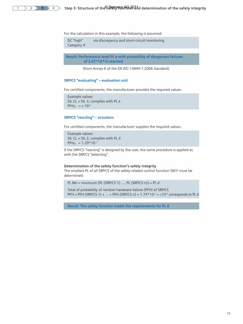
For the calculation in this example, the following is assumed:
DC ”high“ via discrepancy and short-circuit monitoringCategory 4
Result: Performance level PL e with probability of dangerous failures of 2.47*10-8 is reached
(from Annex K of the EN ISO 13849-1:2006 standard)
SRP/CS ”evaluating“ – evaluation unit
For certifi ed components, the manufacturer provides the required values.
Example values: SIL CL = SIL 3, complies with PL e PFHD = < 10-9
SRP/CS ”reacting“ – actuators
For certifi ed components, the manufacturer supplies the required values.
Example values: SIL CL = SIL 2, complies with PL d PFHD = 1.29*10-7
If the SRP/CS “reacting” is designed by the user, the same procedure is applied as with the SRP/CS ”detecting“.
Determination of the safety function’s safety integrityThe smallest PL of all SRP/CS of the safety-related control function SRCF must be determined:
PL Mn = minimum (PL (SRP/CS 1) …..PL (SRP/CS n)) = PL d
Total of probability of random hardware failure (PFH) of SRP/CS PFH = PFH (SRP/CS 1) + … + PFH (SRP/CS n) = 1.74*10-7 = <10-6 corresponds to PL d
Result: The safety function meets the requirements for PL d
15

Category B 1 2 2 3 3 4
DCavg none none low medium low medium high
MTTFd of each channel
low a not a b b c not covered covered
medium b not b c c d not covered covered
high not c c d d d e covered
Step 3: Structure of the safety function and determination of the safety integrity1 2 3 4
Determination of the performance level from category, DC and MTTFd
Although the two standards use different evaluation methods for a safety function, the results are transferable. Simplifi ed procedure for the evaluation of the PL reached by an SPR/CS:
Comparison of SIL and PL
As already demonstrated, the safety function can be evaluated in two different ways. SIL and PL can be compared on the basis of the probability of random hardware failure, see table below.
SIL and PL are mutually transferable
Safety integrity level Probability of dangerous Performance levelSIL failures per hour (1/h) PL
– ≥ 10-5 up to < 10-4 a
SIL 1 ≥ 3 x 10⁻⁶ up to < 10-5 b
SIL 1 ≥ 10-6 up to < 3 x 10⁻⁶ c
SIL 2 ≥ 10-7 up to < 10-6 d
SIL 3 ≥ 10-8 up to < 10-7 e
16
Step 4:
Validation on the basis of the safety plan
Step 4: Validation1 2 3 4
Target: Verifi cation of the imple-mentation of the specifi ed safety requirements
Result: Documented proof with regard to compliance with the safety requirements
The validation serves to check whether the safety system (SRECS) meets the require-ments defi ned by the ”Specifi cation of SRCF“ (from page 7). The safety plan serves as the basis for such validation. The following validation procedure must be followed:
p Definition and documentation of responsibilities
p Documentation of all testsp Validation of each SRCF on the basis of
tests and/or analysesp Validation of the systematic safety
integrity of the SRECS
Planning
The safety plan must be prepared (as dis-cussed on page 7), since the validation is based on this document.
Testing
All safety functions must be tested in accordance with the specifi cation – as described in step 1.
Documentation
The documentation is a basic component of evaluation procedures in case of dam-age. The content of the documentation list is specifi ed by the machinery directive. Basically, the following documents are in-cluded:
p Risk analysisp Risk evaluationp Specification of safety functionsp Hardware components, certificates, etc.p Circuit diagramsp Test resultsp Software documentation, including
signatures, certificates, etc.p Information on usage, including
safety instructions and restrictions for the operator
After a successful validation, the EC declaration of conformity for the risk-minimizing protective measure can be issued.
17

Benefits all along the line: safety from a single source
Integrating safety technology, saving costs
Safety Integrated is the consistent implementation of safety technology in accordance with Totally Integrated Automation – our unique comprehensive and integrated product and system range for the realization of automation solutions. Safety functions are consistently integrated in the standard automation to create a consistent overall system. The advantage for both mechanical engineers and plant operators: considerable cost savings over the entire service life.
No matter which safety tasks you want to complete: the Safety Integrated product portfolio offers everything for detecting, commanding and signaling, evaluating or reacting – from sensors and evaluation units down to the actuator.
Regardless of whether:p you decide in favor of a conventional,
bus-based or control- or drive-based solution (degree of flexibility) and/or
p you require a simple EMERGENCY-STOP function, a simple linking of safety circuits or highly dynamic processes (degree of complexity)
Appendix
Whether detecting, commanding and signaling, evaluating or reacting: with our Safety Integrated product portfolio, we
are the only supplier to cover all safety tasks in the production industry. Seamless safety technology from a single source,
which follows the integrated and consistent concept of Totally Integrated Automation. For you, this implies: safe, reliable
and efficient operation.
SIRIUS – normal B10 values of electromechanical components
The table below lists the normal B10 values and the percentage of dangerous failures for SIRIUS products (operating in high or continuous demand mode).
Siemens SIRIUS product group (electromechanical components)
Normal B10 value
(switching cycles)
Ratio ofdangerous failures
EMERGENCY-STOP control devices (with positive opening contacts)• Pull-to-release• Turn-to-release (also with lock)
30,000100,000
20 %20 %
Cable-operated switches for EMERGENCY-STOP function (with positive opening contacts)
1,000,000 20 %
Standard position switches (with positive opening contacts) 10,000,000 20 %
Position switches with separate actuator (with positive opening contacts)
1,000,000 20 %
Position switches with solenoid interlocking (with positive opening contacts)
1,000,000 20 %
Hinge switches (with positive opening contacts) 1,000,000 20 %
Pushbuttons (non-latching, with positive opening contacts) 10,000,000 20 %
Contactor/motor starter (with positively driven contacts with 3RH/3THand mirror contacts with 3RT/3TF)
1,000,000 73 %
18

Failure Termination of a unit’s capability of fulfi lling a required function.
�, BetaFactor of failure due to common causeCCF faktor: common cause failure factor � (0.1 – 0.05 – 0.02 – 0.01)
B10The B10 value for components subject to wear is expressed in the number of switching cycles, which is the number of switching cycles during which 10 % of specimens failed during a lifetime test. The rate of failure for electromechanical components can be calculated with the B10 value and the operation cycle.
B10dB10d = B10 / ratio of dangerous failures
CCF (common cause failure) Failure due to common cause (e. g. short circuit). Failures of various units due to a single event not based on mutual causes.
DC (diagnostic coverage) Reduced probability of hazardous hardware failures resulting from the execution of automatic diagnostic tests.
Fault tolerance Capability of an SRECS (safety-related electrical control system), a subsystem or subsystem element to further execute a required function in case of faults or failures (resistance to faults).
Functional safety Component of the overall safety, related to the machine and the machine control system, which depends on the correct functioning of the SRECS (safety-related electrical control system), safety-related systems of other technologies and external equipment for risk minimization.
Failure to danger Any malfunction inside the machine or its power supply which increases the risk.
Categories B, 1, 2, 3 or 4 (designated architectures)In addition to qualitative, the categories also contain quantifi able aspects (e. g. MTTFd, DC and CCF). Using a simplifi ed procedure on the basis of the categories as ”designated architectures“, the attained PL (Performance Level) can be assessed.
�, LambdaStatistical rate of failure derived from rate of safe failures (�S) and the rate of failure to danger (�D). FIT (failure in time) represents the Lambda unit.
MTTF / MTTFd (Mean Time To Failure/Mean Time To Failure dangerous)Mean time to a failure or failure to danger. The MTTF can be implemented for components by the analysis of fi eld data or forecasts. With a constant rate of failure, the mean value of the failure-free operation time is MTTF = 1 / �, with Lambda � being the rate of failure of the device. (Statistically, it can be assumed that 63.2 % of the affected components failed after expiry of the MTTF.)
PL (Performance Level)Discrete level which specifi es the capability of safety-related control components of executing a safety function under foreseeable conditions: from PL ”a“ (highest failure probability) to PL ”e“ (lowest failure probability.)
PFHD (Probability of dangerous failure per hour)Probability of a dangerous failure per hour.
Proof test interval or lifetime (T1)Repetitive test for the detection of faults or dete-riorations of an SREC and its subsystems in order to be able to restore the SREC and its subsystems to an ”as new“ state or as closely as practically possible to this state if required.
SFF (safe failure fraction) Share of safe failures in the total rate of failure of a subsystem which does not lead to a failure to danger.
SIL (Safety Integrity Level)Discrete level (one of three possible) for the determination of the safety integrity require-ments of safety-related control functions, which is assigned to the SRECS. Safety Integrity Level 3 represents the highest and Safety Integrity Level 1 the lowest safety integrity level.
SIL CL (Claim Limit)Maximum SIL which can be utilized for an SRECS subsystem with regard to structural limitations and systematic safety integrity.
Safety functionFunction of a machine whose failure may lead to a direct increase of the risk(s).
SRCF (Safety-Related Control Function)Safety-related control function with a specifi ed integrity level executed by the SRECS in order to maintain the machine’s safe state or to prevent a direct increase of risks.
SRECS (Safety-Related Electrical Control System) Safety-related electrical control system of a machine whose failure leads to a direct increase of risks.
SRP/CS (Safety-Related Parts of Control System) Safety-related component of a control which responds to safety-related input signals and generates safety-related output signals.
SubsystemUnit of the SRECS architecture draft on the top-most level. The failure of any subsystem leads to a failure of the safety-related control function.
Subsystem elementPart of a subsystem which comprises an individu-al component or any group of components.
Terms related to functional safety
19
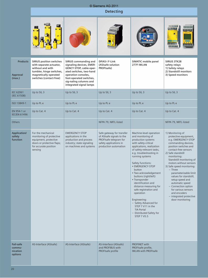
Detecting
Products
Approval (max.)
SIRIUS position switches with separate actuator, without and with tumbler, hinge switches, magnetically operated switches (contact-free)
SIRIUS commanding andsignaling devices, EMER-GENCY-STOP, cable-oper-ated switches, two-hand operation consoles, foot-operated switches, sig-naling columns and integrated signal lamps
DP/AS-i F-Link(ASIsafe solution PROFIsafe)
SIMATIC mobile panel 277F IWLAN
SIRIUS 3TK28 safety relays1) Safety relays2) Standstill monitors3) Speed monitors
IEC 62061 (IEC 61508)
Up to SIL 3 Up to SIL 3 Up to SIL 3 Up to SIL 3 Up to SIL 3
ISO 13849-1 Up to PL e Up to PL e Up to PL e Up to PL e Up to PL e
EN 954-1 orIEC/EN 61496
Up to Cat. 4 Up to Cat. 4 Up to Cat. 4 Up to Cat. 4 Up to Cat. 4
Others NFPA 79, NRTL-listed NFPA 79, NRTL-listed
Application/ safety function
For the mechanical monitoring of protective equipment, protective doors or protective flaps; for accurate position sensing
EMERGENCY-STOP applications in the production and process industry; state signaling on machines and systems
Safe gateway for transfer of ASIsafe signals to the PROFIsafe telegram for safety applications in production automation
Machine-level operation and monitoring of production systems with safety-critical applications, realization of safety-relevant tasks, e.g. troubleshooting in running systems
Safety functions:• EMERGENCY-STOP
button• Two acknowledgement
buttons (right/left)• Transponder
identification and distance measuring for safe registration and operation
Engineering:– Safety Advanced for
STEP 7 V11 in the TIA Portal
– Distributed Safety for STEP 7 V5.5
1) Monitoring of protective equipment, e.g. EMERGENCY-STOP commanding devices, position switches and contact-free sensors
2) Safe standstill monitoring:Standstill monitoring of motors without sensors
3) Safe speed monitoring: – Three
parameterizable limit values for standstill, setup speed and automatic speed
– Connection option for various sensors and encoders
– integrated protective door monitoring
Fail-safe commu-nication options
AS-Interface (ASIsafe) AS-Interface (ASIsafe) AS-Interface (ASIsafe) and PROFIBUS with PROFIsafe profile
PROFINET with PROFIsafe profile,IWLAN with PROFIsafe
20

Evaluating
SIMOCODE pro 3UF7 motor management system with fail-safe expansion modules DM-F
ASIsafe 1) Safe input modules2) Safety monitor (ASIsafe
Solution local)3) Safe AS-i outputs
SIRIUS 3RK3 modular safety system
SIMATIC controllers SIMATIC I/O
Up to SIL 3 Up to SIL 3 Up to SIL 3 Up to SIL 3 Up to SIL 3
Up to PL e Up to PL e Up to PL e Up to PL e Up to PL e
Up to Cat. 4 Up to Cat. 4 Up to Cat. 4 Up to Cat. 4 Up to Cat. 4
NFPA 79, NRTL-listed NFPA 79, NRTL-listed NFPA 79, NRTL-listed NFPA 79, NFPA 85, NRTL-listed, IEC 61511
NFPA 79, NFPA 85, NRTL-listed, IEC 61511
Motor management with integrated safety functions for process automation• Safe motor disconnection• Fail-safe digital module
DM-F Local: For safe disconnection via hardware signal; 2 relay enabling circuits, jointly switching; 2 relay outputs, fail-safely disconnected common potential; inputs for sensor circuit, start signal, cascading and feedback circuit
• Fail-safe digital module DM-F PROFIsafe: For safe disconnection via PROFIBUS/ PROFIsafe; 2 relay enabling circuits, jointly switching; 2 relay outputs, fail-safely disconnected common potential; 1 input for feedback circuit; 3 binary standard inputs
• Setting of the safety functions directly on DM-F Local or in STEP 7 (DM-F PROFIsafe)
Engineering:– Via TIA Portal– Via SIMOCODE ES
1) Safe connection and networking of safety switches and electronic safety sensors
2) All safety applications in production automation:• Monitoring and evaluation
of safe signals via AS-Interface, incl. disconnection on 1 to 2 enabling circuits
• Optional control of safe AS-i outputs for the disconnection of motors or for the control of e.g. safe valves
• Safe coupling of ASIsafe networks
3) Safe distributed disconnection of motors and drives via AS-i• Engineering via TIA Portal
Modular, parameterizable safety system for all safety applications in production automation:• Safe evaluation of
mechanical and contactless protective equipment
• Integrated diagnostic function
• Integrated signal test and discrepancy time monitoring
• Easy realization of safety functions via prefabricated function blocks
Engineering:– Parameterization via
MSS ES– Integration in the
TIA Portal
Scalable, fail-safe controllers• Modular controllers:
CPU315F/317F/319FCPU 414F/416FET 200F-CPU forET 200S and ET 200pro
• Technology controllers with motion control:CPU 317TF-2DP
• PC-based automation:Software controllers, embedded controllers, IPC
Safety functions:• Integrated diagnostics
function • Coexistence of standard and
fail-safe programs on a CPU
Engineering:– Safety Advanced for STEP 7
V11 in the TIA Portal– Distributed Safety for STEP 7
V5.5 with F-FBD and F-LAD as well as integrated library with TÜV-certified safety blocks
– Optional: Library with function blocks for presses and burners
Scalable and redundant I/O systems• ET 200eco• ET 200M• ET 200iSP• ET 200S• ET 200pro
Safety functions:• Integrated signal test
and discrepancy time monitoring
• One distributed I/O system with standard and fail-safe input and output modules
• Configuration of signal test and discrepancy time visualization with STEP 7
Engineering:– Safety Advanced for
STEP 7 V11 in the TIA Portal– Distributed Safety for
STEP 7 V5.5
PROFIBUS with PROFIsafe profile
AS-Interface (ASIsafe) Diagnostics via PROFIBUS • PROFINET with PROFIsafe,IWLAN with PROFIsafe
• PROFIBUS with PROFIsafe profile: all systems
• PROFINET with PROFIsafe profile: ET 200S, ET 200M, ET 200pro (IWLAN interface module available)
21

Reacting
Motor starters for • ET 200S (IP20) • ET 200pro (IP65)
Frequency converters for: • ET 200S • ET 200pro FC
Frequency converters1) SINAMICS G120C (IP20)2) SINAMICS G120 (IP20)3) SINAMICS G120D (IP65)
Frequency converters SINAMICS G130SINAMICS G150
Up to SIL 3 Up to SIL 2 Up to SIL 2 Up to SIL 2
Up to PL e Up to PL d Up to PL d Up to PL d
Up to Cat. 4 Up to Cat. 3 Up to Cat. 3 Up to Cat. 3
NFPA 79, NRTL-listed
All safety applications in production automation and distributed drive tasks as in conveyor technology or lifting drives• Starting and safe dis-
connection with conventional and electronic switching technology
• Integrated motor protection• Safe selective disconnection
(ET 200S)• All advantages of the
SIMATIC ET 200S and SIMATIC ET 200pro systems
Engineering: – Safety Advanced for STEP 7 V11 in
the TIA Portal– Distributed Safety for STEP 7 V5.5
System-integrated, central drive (frequency converter) on standard asynchronous motors without encoders
Integrated, autonomous safety functions:• Safe torque off• Safe stop 1• Safely limited speed
1) Compact frequency converter for applications from 0.37 to 18.5 kW
2) Modular frequency converter for applications from 0.37 to 250 kW
3) Distributed frequency converter in high degree of protection (IP65) for applications from 0.75 to 7.5 kW
The SINAMICS G120 devices are employed for the speed-variable application of asynchronous motors in applications involving conveyor technology, pumps, fans and compressors as well as other equipment such as extruders
Integrated safety functions1):• Safe torque off (STO)• Safe stop 1• Safely limited speed• G120: Safe direction
of rotation• G120: Safe brake control• G120: Safe speed
monitoring
Frequency converters for speed-variable individual drives from 75 to 2700 kW, e.g. pumps, fans, compressors, conveyor belts, extruders, agitators, mills
Integrated safety functions:• Safe torque off• Safe stop 1
• Solution PROFIsafe: PROFIBUS/PROFINET with PROFIsafe profile
• Solution local: on-site safety application
PROFIBUS/PROFINET with PROFIsafe profile
PROFIBUS with PROFIsafe profile, G120 and G120D also PROFINET1) The integrated safety functions can be utilized without sensors; SINAMICS G120C does not support any further safety functions besides STO
PROFIBUS/PROFINET with PROFIsafe profile
22
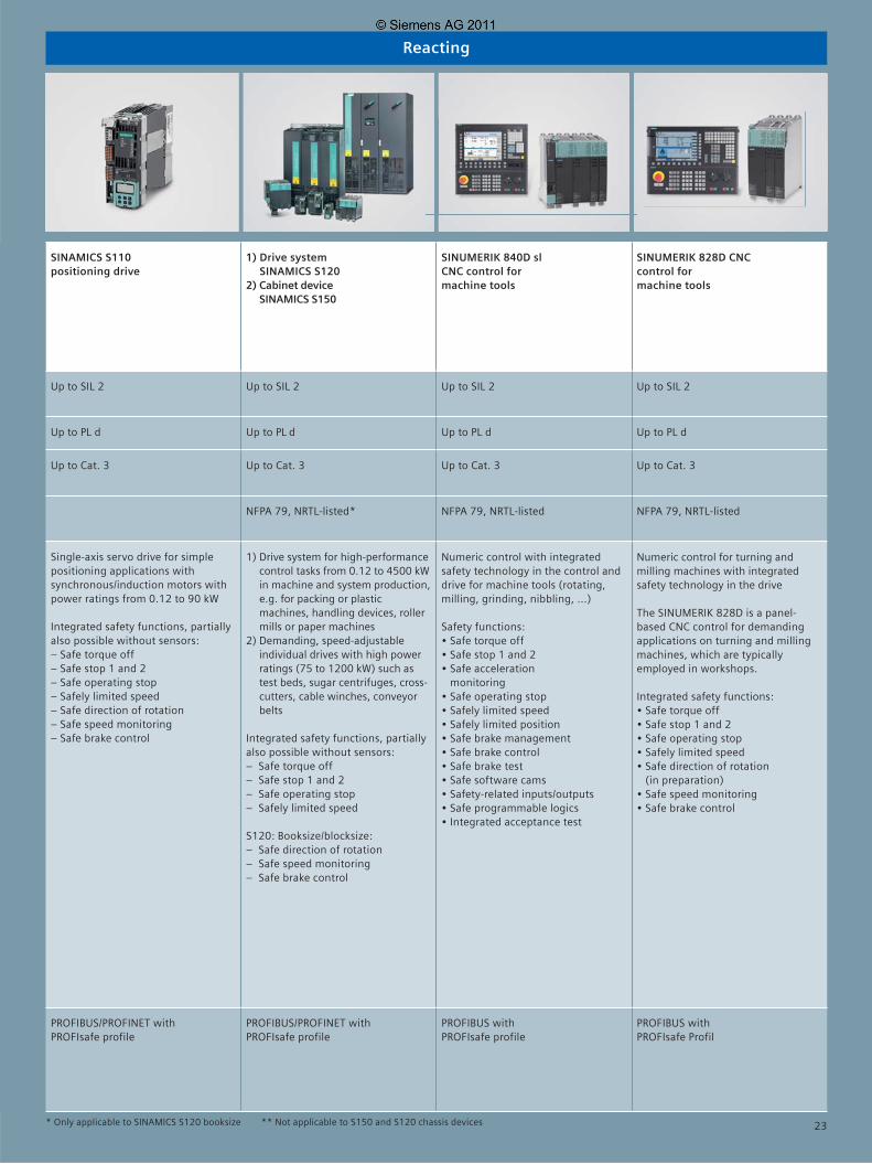
Reacting
SINAMICS S110positioning drive
1) Drive system SINAMICS S120
2) Cabinet device SINAMICS S150
SINUMERIK 840D sl CNC control for machine tools
SINUMERIK 828D CNC control for machine tools
Up to SIL 2 Up to SIL 2 Up to SIL 2 Up to SIL 2
Up to PL d Up to PL d Up to PL d Up to PL d
Up to Cat. 3 Up to Cat. 3 Up to Cat. 3 Up to Cat. 3
NFPA 79, NRTL-listed* NFPA 79, NRTL-listed NFPA 79, NRTL-listed
Single-axis servo drive for simple positioning applications with synchronous/induction motors with power ratings from 0.12 to 90 kW
Integrated safety functions, partially also possible without sensors:– Safe torque off– Safe stop 1 and 2– Safe operating stop– Safely limited speed– Safe direction of rotation– Safe speed monitoring– Safe brake control
1) Drive system for high-performance control tasks from 0.12 to 4500 kW in machine and system production, e.g. for packing or plastic machines, handling devices, roller mills or paper machines
2) Demanding, speed-adjustable individual drives with high power ratings (75 to 1200 kW) such as test beds, sugar centrifuges, cross-cutters, cable winches, conveyor belts
Integrated safety functions, partially also possible without sensors:– Safe torque off– Safe stop 1 and 2– Safe operating stop– Safely limited speed S120: Booksize/blocksize: – Safe direction of rotation– Safe speed monitoring– Safe brake control
Numeric control with integrated safety technology in the control and drive for machine tools (rotating, milling, grinding, nibbling, ...)
Safety functions:• Safe torque off• Safe stop 1 and 2• Safe acceleration
monitoring• Safe operating stop• Safely limited speed• Safely limited position• Safe brake management• Safe brake control• Safe brake test• Safe software cams• Safety-related inputs/outputs• Safe programmable logics• Integrated acceptance test
Numeric control for turning and milling machines with integrated safety technology in the drive
The SINUMERIK 828D is a panel-based CNC control for demanding applications on turning and milling machines, which are typically employed in workshops.
Integrated safety functions:• Safe torque off• Safe stop 1 and 2• Safe operating stop• Safely limited speed• Safe direction of rotation
(in preparation)• Safe speed monitoring• Safe brake control
PROFIBUS/PROFINET withPROFIsafe profile
PROFIBUS/PROFINET with PROFIsafe profile
PROFIBUS with PROFIsafe profile
PROFIBUS with PROFIsafe Profil
* Only applicable to SINAMICS S120 booksize ** Not applicable to S150 and S120 chassis devices 23

www.siemens.com/safety-integrated
Subject to change without prior notice 05/11Order-No.: E20001-A230-M103-V5-7600Dispo 2761021/33938 XX03.52.1.15. 0511 PDFPrinted in Germany © Siemens AG 2011
Siemens AGIndustry Automationand Drive TechnologiesP.O. Box 23 5590713 FÜRTHGERMANY
The information provided in this brochure contains merely general descriptions or characteristics of performance which in actual case of use do not always apply as described or which may change as a result of further development of the products. An obligation to provide the respective characteristics shall only exist if expressly agreed in the terms of contract.
All product designations may be trademarks or product names of Siemens AG or supplier companies whose use by third parties for their own purposes could violate the rights of the owners.

Basic safety requirements in the production industry Basic standards for safety-related control functions
Design and risk evaluation of the machine
EN ISO 12100 Safety of machines Basic terms, general principles
EN ISO 14121-1 Safety of machines Risk assessment, part 1: principles
Functional and safety-relevant requirements for safety-related control systems
Development and realization of safety-related control systems
EN 62061: 2005Safety of machines Functional safety of safety-related electrical, electronic and programmableelectronic control systems
Any architecturesSafety Integrity Level (SIL)SIL 1, SIL 2, SIL 3
EN ISO 13849-1: 2006Safety of machinesSafety-related parts of control systems, part 1: general principles Successor standard of EN 954-1: 1996 Transition period until end of 2011
Provided architectures (categories)Performance Level (PL)PL a, PL b, PL c, PL d, PL e
Electrical safety aspects
EN 60204-1 Safety of machines Electrical equipment of machines, part 1: general requirements
1. Determination of the machine limits
2. Identifi cation of hazards, risk estimation, risk evaluation
3. Risk estimation for all identifi ed hazards and hazardous situations
4. Risk evaluation and decision-making aimed at risk minimization
5. Elimination of hazards or minimization of the risk connected with the hazard through measures (3-step method: inherent design, safeguarding,information for use)
EN 14121 contains detailed information on steps 1–4.
Strategy for risk minimization in acc. with EN ISO 12100-1
Determination of risk-minimizing measures on the basis of an iterative process:
Development and realization of safety-related control systems
Applicable with safety-related electrical, electronic and programmable electronic control systems (SRECS) for machines
Applicable with safety-related control parts or any machine type, irrespective of the employed technology and energy (electrical, hydraulic, pneumatic, mechanical, etc.)
EN 62061: 2005 (sector standard within the scope of IEC 61508) EN ISO 13849-1: 2006 (successor standard of EN 954-1:1996, transition period until end of 2011)
Safety planStrategy for the realization of safety function, responsibilities, maintenance…
Risk evaluationSeverity of damage Se
Riskrelated to the identifi ed hazard
Occurrence probability PrProbability of avoiding or limiting harm Av
Frequency and duration ofexposure to hazard Fr
= and
Determination of the required SIL(by SIL assignment)
Procedure1. Determination of damage severity Se2. Determination of points for frequency Fr, occurrence probability Pr and prevention Av 3. Total of points Fr + Pr + Av = class Cl4. Interface line severity S and column Cl = required SIL
a
b
c
d
e
Layout of the safety function and determination of the attained safety integrity
Safety Integrity Level Probability of dangerous Performance LevelSIL failures per hour (1/h) PL
– ≥ 10-5 to < 10-4 a
SIL 1 ≥ 3 x 10⁻⁶ to < 10-5 b
SIL 1 ≥ 10-6 to < 3 x 10⁻⁶ c
SIL 2 ≥ 10-7 to < 10-6 d
SIL 3 ≥ 10-8 to < 10-7 e
oror
CE marking (declaration of conformity)
oror
Other measures
+++ +
SIL and PL can be mapped on each other
Validation based on validation plan
Verifi cation of the specifi ed safety requirements’ implementation
Planning Testing Documenting
Functional Safety in Machines and Systems –Easy Implementation of the European Machinery Directive
Safety requirements
Article 95 EC Treaty(free movement of goods)
Article 137 EC Treaty(industrial safety)
e. g. machines
Low-voltage directive
(2006/95/EC)
Machinery directive
(2006/42/EC)
Harmonized European standards
Manufacturer
”Industrial safety“ framework directive (89/391/EEC)
Separate directive ”Use of operating
equipment“ (89/655/EC)
National laws
User
Harmonized standards(presumption of conformity)
Effects Severity Class
Se Cl = Fr + Pr + Av 3–4 5–7 8–10 11–13 14–15
Death, loss of eye or arm 4 SIL 2 SIL 2 SIL 2 SIL 3 SIL 3
Permanent, loss of fi ngers 3 SIL 1 SIL 2 SIL 3
Reversible, medical treatment 2 SIL 1 SIL 2
Reversible, fi rst aid 1 SIL 1
Frequency Occurrence probability of Preventionand/or duration of stay hazardous situation possibilities
Fr Pr Av≤ 1 h 5 frequently 5
> 1 h to ≤ 1 day 5 probable 4
> 1 day to ≤ 2 weeks 4 possible 3 impossible 5
> 2 weeks to ≤ 1 year 3 rarely 2 possible 3
> 1 year 2 negligible 1 probable 1
Determination of the required PL(by risk graph)
Risk parameters
S = Severity of injury
S1 = Slight (usually reversible) injury
S2 = Severe (usually irreversible) injury, including death
F = Frequency and/or duration of stay (exposure to hazard)
F1 = Rare to often and/or short exposure to hazard
F2 = Frequent to continuous and/or long exposure to hazard
P = Probability of avoiding or limiting harm
P1 = Possible under certain conditions
P2 = Hardly possible
a, b, c, d, e = targets of the safety-related performance level
Low risk
High risk
Required performance
level PL
Starting point for estimation of risk minimization
Determination of CCF factor from 1% to 10 % acc. to table F.1 of standard.
If required, adding of failure probability of fail-safe communication.
User (e. g. mechanical engineer)
Manufacturer (products, components)
Results
Partial system detecting Partial system evaluating Partial system reacting
SRECS Sensors Evaluation unit Actuators
Draft Use of Use of Draft Use of by user certifi ed certifi ed by user certifi ed components components components
Partial system Architecture selection Architecture selectionLambda calculation with calculation with
Electromechanical part • B10 value • B10 value
Operation cycle • C (switching cycles/h) • C (switching cycles/h)
DC 0 ... 99 % 0 ... 99 %
SIL CL or SIL 1, 2 or 3 SIL 1, 2 or 3 SIL 1, 2 or 3 SIL 1, 2 or 3 SIL 1, 2 or 3derivation of
SIL CL from PL
Failure Calculation with basic Manufacturer Manufacturer Calculation with basic Manufacturerprobability of PFH partial system architectures specifi cation specifi cation partial system architectures specifi cation
Partial result Partial result Partial result sensors unit actuators
Attainable SIL is derived from lowest SIL of partial results and total failure probability PFH
User (e. g. mechanical engineer)
Manufacturer (products, components)
Results
All sensors together form an SRP/CS.
All actuators together form an SRP/CS (calculation using 1/MTTFd = 1/MTTFd1 + 1/MTTFd2...).
The CCF factor is assumed to be 2 % if certain criteria are fulfi lled (table F.1 of standard).
If required, adding of failure probability of fail-safe communication.
SRP/CS detecting SRP/CS evaluating SRP/CS reacting
SRP/CS Sensors Evaluation unit Actuators
Draft Use of Use of Draft Use of by user certifi ed certifi ed by user certifi ed components components components
Category Architecture selection Architecture selectionMTTFd calculation with calculation with
Electromechanicalpart • B10 value • B10 value
Operation cycle • C (switching cycles/h) • C (switching cycles/h)
DC 0 ... 99 % 0 ... 99 %
PL or PL a, b, c, d or e PL a, b, c, d or e PL a, b, c, d or e PL a, b, c, d or e PL a, b, c, d or ederivation of PL
from SIL CL
Failure probability Tabular assignment Manufacturer Manufacturer Tabular assignment Manufacturer
or PFH (annex K of standard) specifi cation specifi cation (annex K of standard) specifi cation
Partial result Partial result Partial result sensors unit actuators
Attainable PL is derived from lowest PL of partial resultsand total failure probability PFH
Failure Termination of a unit’s capability of fulfi lling a required function.
�, BetaFactor of failure due to common cause CCF factor: common cause failure factor ß (0.1 – 0.05 – 0.02 – 0.01).
B10The B10 value for components subject to wear is expressed in the number of switching cycles, which is the number of switching cycles during which 10 % of specimens failed during a lifetime test. The rate of failure for electromechanical components can be calculated with the B10 value and the operation cycle.
B10dB10d = B10 / ratio of dangerous failures
CCF (common cause failure) Failure due to common cause (e. g. short circuit). Failures of various units due to a single event not based on mutual causes.
DC (diagnostic coverage)Reduced probability of hazardous hardware failures resulting from the execution of automatic diagnostic tests.
Fault tolerance Capability of an SRECS (safety-related electrical control system), a partial system or partial system element to further execute a required function in case of faults or failures (resistance to faults).
Functional safety Part of the overall safety, related to the machine and the machine control system, which depends on the correct functioning of the SRECS (safety-related electrical control system), safety-related systems of other technologies and external equipment for risk minimization.
Failure to danger Any malfunction inside the machine or its power supply which increases the risk.
Categories B, 1, 2, 3 or 4 (provided architectures)In addition to qualitative, the categories also contain quantifi able aspects (e. g. MTTFd, DC and CCF). Using a simplifi ed procedure on the basis of the categories as ”provided architectures“, the attained PL (Performance Level) can be assessed.
�, LambdaStatistical rate of failure derived from the rate of safe failures (�
S)
and the rate of failure to danger (�D). FIT (failure in time) represents
the Lambda unit.
MTTF / MTTFd (Mean Time to Failure / Mean Time to Failure dangerous)Mean time to a failure or failure to danger. The MTTF can be implemented for parts by the analysis of fi eld data or forecasts. With a constant rate of failure, the mean value of the failure-free operation time is MTTF = 1 / �, with Lambda � being the rate of failure of the device. (Statistically, it can be assumed that 63.2 % of the affected parts failed after expiry of the MTTF.)
PL (Performance Level)Discrete level which specifi es the capability of safety-related control parts of executing a safety function under foreseeable conditions: from PL ”a“ (highest failure probability) to PL ”e“ (lowest failure probability).
PFHD
Probability of a dangerous failure per hour.
Proof test interval or lifetime (T1)Repetitive test for the detection of faults or deteriorations of an SREC and its partial systems in order to be able to restore the SREC and its partial systems to an ”as new“ state or as closely as practically possible to this state if required.
SFF (safe failure fraction) Share of safe failures in the total rate of failure of a partial system which does not lead to a failure to danger.
SIL (Safety Integrity Level) Discrete level (one of three possible) for the determination of the safety integrity requirements of safety-related control functions, which is assigned to the SRECS. Safety Integrity Level 3 represents the highest and Safety Integrity Level 1 the lowest safety integrity level.
SIL CL (Claim Limit)Maximum SIL which can be utilized for an SRECS partial system with regard to structural limitations and systematic safety integrity.
Safety functionFunction of a machine whose failure may lead to a direct increase of the risk(s).
SRCF (Safety-Related Control Function)Safety-related control function with a specifi ed integrity level executed by the SRECS in order to maintain the machine’s safe state or to prevent a direct increase of risks.
SRECS (Safety-Related Electrical Control System) Safety-related electrical control system of a machine whose failure leads to a direct increase of risks.
SRP/CS (Safety-Related Parts of Control System) Safety-related part of a control which responds to safety-related input signals and generates safety-related output signals.
Partial systemUnit of the SRECS architecture draft on the topmost level. The failure of any partial system leads to a failure of the safety-related control function.
Partial system elementPart of a partial system which comprises an individual part or any group of parts.
E20
00
1-Y
29
0-M
10
3-V
5-7
60
0
Safety IntegratedAnswers for industry.
F1
F2
F1
F2
S1
S2
A1
A2
A1
A2
A1
A2
A1
A2