Systems engineering approach to functional safety and ...
18
Safety and Reliability of Systems and Processes, Summer Safety and Reliability Seminar 2020 © Gdynia Maritime University. All rights reserved. DOI: 10.26408/srsp-2020-10 135 Kosmowski Kazimierz T. 0000-0001-7341-6750 Gdańsk University of Technology, Gdańsk, Poland, kazkosmo (at) pg.edu.pl Systems engineering approach to functional safety and cyber security of industrial critical installations Keywords systems engineering, functional safety, cyber security, control systems, cyber physical systems Abstract This chapter addresses the systems engineering approach to integrated functional safety and cybersecurity analysis and management regarding selected references, standards and requirements concerning critical installations and their industrial automation and control system (IACS). The objective is to mitigate the vulnerability of industrial installations that include the information technology (IT) and the operational technology (OT) to reduce relevant risks. This approach includes verifying the safety integrity level (SIL) of defined safety functions, and then to check the level obtained taking into account the security assurance level (SAL) of particular domain, such as a safety related control system (SRCS), in which given safety function is to be implemented. The SAL is determined based on a vector of fundamental requirements (FRs). The method proposed uses defined risk graphs for the individual and/or the societal risk, and relevant risk criteria, for determining the SIL required of given safety function, and probabilistic models to verify the SIL achievable for the SRCS architecture to be designed and then implemented in an industrial installation. 1. Introduction The complexity of industrial systems and networks, sometimes without clear hierarchy in information flow for controlling various processes, operating in changing internal and external environment, emerging of new hazards and threats, can make significant challenges to reach in practice a high level of the system reliability and safety [5]. No less important are in such systems the security-related issues, especially those influencing potentially the risk of high consequence losses [25]. An important issue in industrial practice is the business continuity management (BCM) [14] that requires careful consideration of various aspects within an integrated RAMS&S (reliability, availability, maintainability, safety, and security) framework. In such analyses the risk evaluation and management in life cycle is of special interest for both the industry and insurance companies [25]. Such issues are of significant interest also in the domain of the performability engineering that has been stimulated by Misra for years [29]. In this chapter an approach is proposed for the integrated functional safety and cybersecurity analysis and management in critical installations of hazardous plants in the context of the design and operation of the industrial automation and control systems (IACSs) [11], [26]. The idea of Industry 4.0 assumes the openness of markets and flexible cooperation of companies worldwide [13], [27]. It could not be effective without coordinating relevant international standardization. The main objective of this chapter is to outline a conceptual framework for integrated analyses of the functional safety solutions according to generic functional safety standard IEC 61508 (7 parts) [8], and the IACS cyber security, outlined in IEC 62443 (14 parts) [11]. For reducing vulnerability of the IT and OT systems and mitigating risks of hazardous events, especially of high consequences, a set of seven fundamental requirements (FRs), defined in the IEC 62443-1 standard, is taken into account to determine the SAL of the domain to be considered. The method proposed uses the individual and/or societal risk graphs for determining the safety integrity level required (SILr) [8], [21] of consecutive safety functions to be defined in the analyses.
Transcript of Systems engineering approach to functional safety and ...

Safety and Reliability of Systems and Processes, Summer Safety and Reliability Seminar 2020 © Gdynia Maritime University. All rights reserved. DOI: 10.26408/srsp-2020-10
135
Kosmowski Kazimierz T. 0000-0001-7341-6750
Gdańsk University of Technology, Gdańsk, Poland, kazkosmo (at) pg.edu.pl
Systems engineering approach to functional safety and cyber security
of industrial critical installations
Keywords
systems engineering, functional safety, cyber security, control systems, cyber physical systems
Abstract
This chapter addresses the systems engineering approach to integrated functional safety and cybersecurity
analysis and management regarding selected references, standards and requirements concerning critical
installations and their industrial automation and control system (IACS). The objective is to mitigate
the vulnerability of industrial installations that include the information technology (IT) and the operational
technology (OT) to reduce relevant risks. This approach includes verifying the safety integrity level (SIL)
of defined safety functions, and then to check the level obtained taking into account the security assurance
level (SAL) of particular domain, such as a safety related control system (SRCS), in which given safety
function is to be implemented. The SAL is determined based on a vector of fundamental requirements (FRs).
The method proposed uses defined risk graphs for the individual and/or the societal risk, and relevant risk
criteria, for determining the SIL required of given safety function, and probabilistic models to verify the SIL
achievable for the SRCS architecture to be designed and then implemented in an industrial installation.
1. Introduction
The complexity of industrial systems and networks,
sometimes without clear hierarchy in information
flow for controlling various processes, operating
in changing internal and external environment,
emerging of new hazards and threats, can make
significant challenges to reach in practice a high
level of the system reliability and safety [5]. No less
important are in such systems the security-related
issues, especially those influencing potentially
the risk of high consequence losses [25].
An important issue in industrial practice is
the business continuity management (BCM) [14] that
requires careful consideration of various aspects
within an integrated RAMS&S (reliability,
availability, maintainability, safety, and security)
framework. In such analyses the risk evaluation
and management in life cycle is of special interest
for both the industry and insurance companies [25].
Such issues are of significant interest also
in the domain of the performability engineering that
has been stimulated by Misra for years [29].
In this chapter an approach is proposed
for the integrated functional safety and cybersecurity
analysis and management in critical installations
of hazardous plants in the context of the design
and operation of the industrial automation
and control systems (IACSs) [11], [26]. The idea
of Industry 4.0 assumes the openness of markets
and flexible cooperation of companies worldwide
[13], [27]. It could not be effective without
coordinating relevant international standardization.
The main objective of this chapter is to outline
a conceptual framework for integrated analyses
of the functional safety solutions according
to generic functional safety standard IEC 61508
(7 parts) [8], and the IACS cyber security, outlined
in IEC 62443 (14 parts) [11]. For reducing
vulnerability of the IT and OT systems
and mitigating risks of hazardous events, especially
of high consequences, a set of seven fundamental
requirements (FRs), defined in the IEC 62443-1
standard, is taken into account to determine the SAL
of the domain to be considered.
The method proposed uses the individual and/or
societal risk graphs for determining the safety
integrity level required (SILr) [8], [21] of consecutive
safety functions to be defined in the analyses.

Kosmowski Kazimierz T.
136
The SILr is then verified to indicate SIL achieved
in the safety related control system (SRCS)
of architecture proposed, in which given safety
function will be implemented.
For that purpose, the probabilistic model of SRCS is
to be developed regarding potential common cause
failure (CCF), when the redundancy of hardware is
necessary. Then, the verified SIL is to be validated
regarding the security assurance level (SAL) [11],
determined for relevant domain, for instance
the domain of SRCS in which given safety
function is to be implemented, including internal
and communications.
In the analyses and assessments to be carried
out, both quantitative and qualitative information
available is used, including expert opinions.
The analyses and assessments are based on defined
classes of distinguished categories of concepts.
For related evaluations, some performance indicators
are useful, also so-called key performance indicators
(KPIs), defined in some standards and publications,
for instance [15], [25].
2. Systems engineering perspective
on the functional safety and cyber security
Systems engineering (SE) consists of two general
disciplines: the technical knowledge domain
in which the systems engineer operates, and systems
engineering management [30]. It is defined concisely
as an interdisciplinary engineering management
process that evolves and verifies an integrated, life-
cycle balanced set of system solutions to satisfy the
customer needs.
The SE process includes [30]:
requirements analysis (analysing missions
and environments, identifying functional
requirements, defining / refining performance
and design, and constraint requirements),
functional analysis / allocation (decomposing
to lower-level functions, allocating
performance and other limiting requirements
to all functional levels, defining / refining
functional interfaces, both internal
and external, defining / refining / integrating
functional architecture),
synthesis (transforming architectures from
functional to physical, defining alternative
system concepts, configuring items
and system elements, selecting preferred
product and process solutions, defining
/ refining physical interfaces, both internal and
external.
In the functional safety analysis and life cycle
management [9], [19] a set of safety functions is
to be defined in safety critical installations
considering the results of hazards identification,
while the safety integrity requirements result from
analysis of potential hazardous events. Higher safety
integrity levels impose more strict requirements
on the architecture design of the safety-related
systems [24].
In order to deal in a systematic manner with
all activities necessary to achieve the required safety
integrity for the safety functions to be carried out
by the E/E/PE system, the standard IEC 61508
adopts an overall framework for the safety
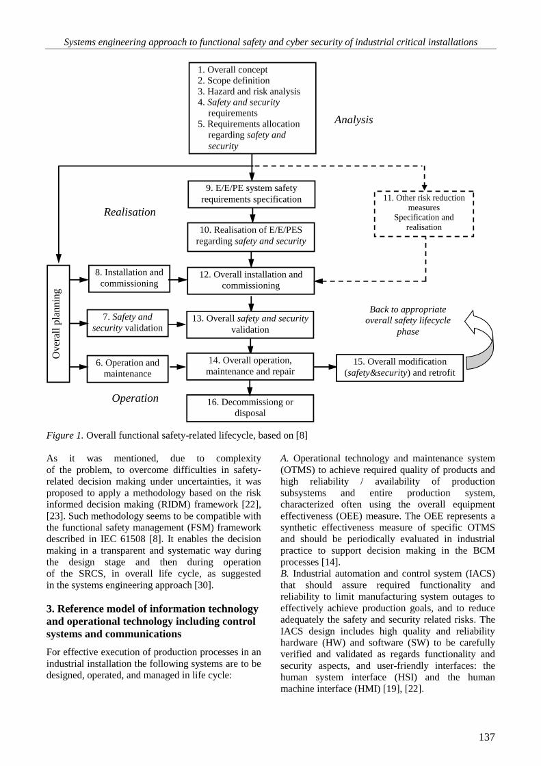
management in lifecycle. A simplified scheme
is shown in Figure 1 that should include also the
cyber security related aspects, especially in steps
1, 3, 4, 5 of the analysis, and then 7, 10, 13, and 15
during the E/E/PE system realization and its
operation.
All activities related to the functional safety and
security management that include determining of the
safety function SIL and its verification are not
directly shown in Figure 1. They should be carefully
specified for hardware of the E/E/PE system or SIS
(safety instrumented system) [9], software and
human factors to avoid as much as possible both the
random failures and systematic failures [7], [8]. The
requirements concerning functional safety and cyber
security management shall run in parallel with the
overall safety lifecycle phases.
According to IEC 61508 the safety validation should
be performed in terms of the overall safety function
requirements and the overall safety integrity
requirements, considering the safety requirements
allocation for the E/E/PE safety-related system
during its designing.
Usually, considerable uncertainty is involved in the
risk assessment to determine SIL of consecutive
safety functions. The SIL verifying is based on the
results obtained from a probabilistic model
developed for the SRCS. In the risk assessment for
decision making, also the results of a cost-benefit
analysis (CBA) are valuable to indicate, which a risk
control option (RCO) gains the advantage over
a initial option considered, fulfilling relevant
requirements and criteria [21]. It was shown in some
case studies that a more costly option as regards the
capital investment for increasing SIL of given SRCS,
for instance from SIL2 to SIL3, can be more justified
due to lower the life cycle costs (LCC) [21].
Systems engineering approach to functional safety and cyber security of industrial critical installations
137
1. Overall concept
2. Scope definition
3. Hazard and risk analysis
4. Safety and security
requirements
5. Requirements allocation
regarding safety and
security
12. Overall installation and
commissioning
6. Operation and
maintenance
7. Safety and
security validation
8. Installation and
commissioning
Ov
eral
l pla
nn
ing
11. Other risk reduction
measures
Specification and
realisation
Back to appropriate
overall safety lifecycle
phase
9. E/E/PE system safety
requirements specification
10. Realisation of E/E/PES
regarding safety and security
13. Overall safety and security
validation
14. Overall operation,
maintenance and repair
16. Decommissiong or
disposal
15. Overall modification
(safety&security) and retrofit
Analysis
Realisation
Operation
Figure 1. Overall functional safety-related lifecycle, based on [8]
As it was mentioned, due to complexity
of the problem, to overcome difficulties in safety-
related decision making under uncertainties, it was
proposed to apply a methodology based on the risk
informed decision making (RIDM) framework [22],
[23]. Such methodology seems to be compatible with
the functional safety management (FSM) framework
described in IEC 61508 [8]. It enables the decision
making in a transparent and systematic way during
the design stage and then during operation
of the SRCS, in overall life cycle, as suggested
in the systems engineering approach [30].
3. Reference model of information technology
and operational technology including control
systems and communications
For effective execution of production processes in an
industrial installation the following systems are to be
designed, operated, and managed in life cycle:
A. Operational technology and maintenance system
(OTMS) to achieve required quality of products and
high reliability / availability of production
subsystems and entire production system,
characterized often using the overall equipment
effectiveness (OEE) measure. The OEE represents a
synthetic effectiveness measure of specific OTMS
and should be periodically evaluated in industrial
practice to support decision making in the BCM
processes [14].
B. Industrial automation and control system (IACS)
that should assure required functionality and
reliability to limit manufacturing system outages to
effectively achieve production goals, and to reduce
adequately the safety and security related risks. The
IACS design includes high quality and reliability
hardware (HW) and software (SW) to be carefully
verified and validated as regards functionality and
security aspects, and user-friendly interfaces: the
human system interface (HSI) and the human
machine interface (HMI) [19], [22].
Kosmowski Kazimierz T.
138
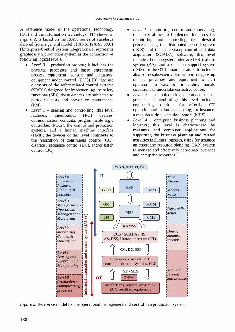
A reference model of the operational technology
(OT) and the information technology (IT) shown in
Figure 2, is based on the ISA99 series of standards
derived from a general model of ANSI/ISA-95.00.01
(Enterprise-Control System Integration). It represents
graphically a production system as the connection of
following logical levels.
Level 0 production process; it includes the
physical processes and basic equipment:
process equipment, sensors and actuators,
equipment under control (EUC) [8] that are
elements of the safety-related control systems
(SRCSs) designed for implementing the safety
functions (SFs); these devices are subjected to
periodical tests and preventive maintenance
(PM).
Level 1 – sensing and controlling; this level
includes: input/output (I/O) devices,
communication conduits, programmable logic
controllers (PLCs), the control and protection
systems, and a human machine interface
(HMI); the devices of this level contribute to
the realization of continuous control (CC),
discrete / sequence control (DC), and/or batch
control (BC).
Level 2 – monitoring, control and supervising;
this level allows to implement functions for
monitoring and controlling the physical
process using the distributed control system
(DCS) and the supervisory control and data
acquisition (SCADA) software; this level
includes: human-system interface (HSI), alarm
system (AS), and a decision support system
(DSS) for the OT human operators; it includes
also some subsystems that support diagnosing
of the processes and equipment to alert
operators in case of impending unsafe
conditions to undertake corrective action.
Level 3 – manufacturing operations mana-
gement and monitoring; this level includes
engineering solutions for effective OT
operation and maintenance using, for instance,
a manufacturing execution system (MES).
Level 4 – enterprise business planning and
logistics; this level is characterized by
measures and computer applications for
supporting the business planning and related
activities including logistics, using for instance
an enterprise resource planning (ERP) system
to manage and effectively coordinate business
and enterprise resources.
Level 3
Manufacturing
Operations
Management /
Monitoring
Level 2
Monitoring,
Control &
Supervising
MES
DCS / SCADA / HSI
AS, DSS, Human operators (OT)
Level 1
Sensing and
Controlling /
Manipulating
I/O devices, conduits, PLC,
control / protection systems, HMI
Level 0
Production /
manufacturing
processes
Installations, sensors, actuators /
EUC, auxiliary equipment
Level 4
Enterprise
Business
Planning &
Logistics
ERP
Ind
ust
rial
au
tom
ati
on
an
d c
on
trol
syst
em (
IAC
S)
Time
Frame:
Months,
weeks
Days, shifts,
hours
Hours,
minutes,
seconds
Minutes,
seconds,
milliseconds
CC, DC, BC
IT
OT
SF - SRS
T/PM
CMM
MOM
CME
WAN, Internet, CT
BCM
RAMSS
QM
EM
Figure 2. Reference model for the operational management and control in a production system

Systems engineering approach to functional safety and cyber security of industrial critical installations
139
On the right side of Figure 2 the time frame
categories for typical information processing, to be
carried out at the distinguished levels of this
reference model, are presented. The time windows
range from milliseconds on the levels 0 and 1 (for
instance the controlling and protecting signals) to
weeks and months at the level 4 (periodical big data
analysis for supporting long-term decision making
within the ERP and logistics). In case of dynamic
processes on levels 0, 1 and 2 it causes difficulties in
designing of the reliable control systems and
communication conduits for the safety and security-
related protections due to a very short reaction time
required.
An example of simplified architecture of the OT, IT,
and CT interrelated systems and networks is
illustrated in Figure 3. The OT is nowadays in the
process of adopting similar network technologies as
defined in the IT domain at an increasing rate, so
these two worlds begin to merge. It is expected that
the use of CT with advanced applications (APP), in
favor of IT and OT, will make additional business
models and automation structures possible and
profitable, for instance using an open platform
communications unified architecture (OPC UA) and
automation mark-up language (AutomationML),
being lately in dynamic development for advanced
technological Industry 4.0 solutions [4], [27], [32].
Combining of these domains is often referred to as
the internet of things (IoT) or the industrial internet
of things (IIoT) [13], [27]. However, this merging
can have potential to cause some cybersecurity
related problems that require special treatment in the
design and in operation of the IT and OT systems
and networks [6].
Switch
Switch
Edge cloud
Router
Firewall
Servers
Cloud
Internet
WAN
Edge
Gateway
BPCS
(DCS /
SCADA)
SIS
Safety PLC
SRCS
Safety PLC Relay Logic
Plant I/O Plant I/O Plant I/O
IT CT
OT
APP APP
Figure 3. Interrelated domains OT, IT, and CT, based on [4]
Below an approach is outlined for integrated
functional safety and cybersecurity evaluation
to mitigate risks for potential hazards and threats.
In the functional safety approach the safety functions
[8], [10] are defined to be implemented within
the SRCS of appropriate architecture, for instance,
the basic process control system (BPCS) [8]
or the safety instrumented system (SIS) in process
industry [9].
In case of manufacturing machinery using the safety
PLCs or the relay logic solutions [10] (see the OT
part in Figure 3). Adoption of integrated networks
within the OT and IT systems may be of interest
regarding costs, but the requirements for applications
in the field of OT and IT are quite different, which
might lead to serious challenges in bridging these
functionally different technological domains [3], [6],
[28], [31].

Kosmowski Kazimierz T.
140
4. Verifying the safety integrity relevels
of functions implemented for reducing risks
4.1. SIL determination and verification
The functional safety is defined as a part of general
safety of an industrial plant critical installation
or production lines, which depends on a proper
response of the SRCS during potential abnormal
situation or accident to avoid or limit undesirable
consequences. The functional safety methodology
has been formulated in the generic standard IEC
61508 [8] and is appreciated in industry in the design
and operation of the programmable E/E/PE systems
in life cycle.
Different names of the SRCS are used in various
industrial sectors, for example, a safety instrumented
system (SIS) in case of the process industry sector
[9], or a safety-related electrical control system
(SRECS) for machinery [10]. Such systems are to be
designed to perform specified safety functions to
ensure that evaluated risk is reduced to a level
specified for the particular industrial installation, and
then maintained at the specified tolerable level in life
cycle [20]–[21].
Two different requirements should be specified
to ensure appropriate level of functional safety [8]:
the requirements imposed on the performance
of safety function designed for the hazard
identified,
the safety integrity requirements, i.e. the
probability that the safety function will be
performed in a satisfactory way when potential
hazardous situation occurs.
Table 1. Categories of SIL and probabilistic criteria
to be assigned to the SRCS that operates in LDM
or HCM
SIL PFDavg PFH [h-1]
4 [10-5, 10-4) [10-9, 10-8)
3 [10-4, 10-3) [10-8, 10-7)
2 [10-3, 10-2) [10-7, 10-6)
1 [10-2, 10-1) [10-6, 10-5)
The safety integrity is defined as the probability that
a safety-related system, such as the E/E/PE system
or SIS, will satisfactorily perform defined safety
function under all stated conditions within given
time. For the safety-related system, in which defined
safety function is to be implemented, two
probabilistic criteria are defined as presented
in Table 1 for four categories of the SIL [8]–[9],
namely:
the probability of failure on demand average
(PFDavg) of the SRCS in which a safety
function considered is to be implemented,
operating in a low demand mode (LDM),
or
the probability of a dangerous failure per hour
(PFH) of the SRCS operating in a high or
continuous mode (HCM).
The SIL requirements assigned for the SRCS to be
designed for implementing specified safety function
stem from the results of the risk analysis and
assessment to reduce sufficiently the risk of losses
taking into account specified risk criteria, namely for
the individual risk and/or the group or societal risk
[8]. If the societal risk is of interest, the analyses can
be generally oriented on three distinguished
categories of losses, namely [8]–[9]: health (H),
environment (E) or material (M) damage, then the
SIL required (SILr) for particular safety function, is
determined as follows
).,,max( M
r
E
r
H
rrSILSILSILLIS
(1)
As it was mentioned above, generally the SIL
verification can be carried out for two operation
modes, namely: LDM or HCM. The former is
characteristic for the process industry [9], and the
latter is typical for the machinery [10] or the railway
transportation systems, and also for monitoring and
the real time control of any installation using the
DCS / SCADA technology.
Typical hardware architecture of the E/E/PE system,
shown in Figure 4, usually consists of three
subsystems [21]: (A) sensors and input devices
(transducers, converters etc.), (B) logic device
(safety PLC or safety relay modules), and (C)
actuators, i.e. the EUC or other output devices.
A. Sensors
KAooNA
B. Logic
KBooNB
C. Actuators
KCooNC
Communication
Electric power
supply
Figure 4. Typical architecture of the E/E/PE system or SIS in which a safety function is implemented

Systems engineering approach to functional safety and cyber security of industrial critical installations
141
Such safety-related system constitutes a specific
architecture of the hardware and software modules,
and communication conduits. The logic device
comprises typically a safety PLC with its input and
output modules. The subsystems shown in Figure 4
can be generally of K out of N (KooN) configuration,
for instance 1oo1, 1oo2 or 2oo3. Their hardware
fault tolerance (HFT) is understood as ability of the
subsystem to perform a required function in the
presence of faults or errors. The HFT (0, 1, 2) is an
important parameter to be considered in the final SIL
verification of given subsystem, together with the
value of a safe failure fracture (SFF) [8].
Any redundant system, also the SRCS, is prone
to a common cause failure (CCF) that contributes
significantly to decreasing its dependability due to
potential failure mechanisms regarding relevant site-
specific influence factors. The CCF is a potential
failure resulting in one or more elements, causing
coincident failures of two or more channels
in redundant subsystem, leading to a failure of entire
system. The multiple failures may occur
simultaneously or over a period, shorter than testing
time interval.
Various probabilistic models are proposed to deal
with CCF in safety-related systems, in particular
the E/E/PE system or SIS. The CCF contribution
in the PFDavg or PFH is often incorporated using
a modified -factor method in probabilistic
modelling of redundant system considered [8], [24].
If diagnostic tests run in each channel that can detect
and reveal only a fraction of the failures, it is
justified to divide all failures into two categories: (1)
those that lie outside the coverage of the diagnostic
tests (can not be detected) and (2) those that lie
within the coverage (detected by the diagnostic
tests). The overall failure event probability per time
unit of the subsystem dangerous (D) failure due
to potential failures including CCF, is a function
of parameters to be included in the formula below
[24]
,...),(DDdDu
CCF
DfPF
(2)
where:
Du is the rate of dangerous (D), undetected (u)
failure in a single channel, influencing the
probability of failures that lie outside the
coverage of the diagnostic tests; is the
common cause failure factor for undetectable
dangerous faults, which is equal to the overall
β-factor that would be applicable in the
absence of diagnostic testing,
λDd is the rate of a dangerous (D), detected (d)
failure in a single channel, influencing the
probability of failures that lie within the
coverage of the diagnostic tests, D is the
common cause failure factor for detectable
dangerous faults; as the repetition rate of the
diagnostic testing is increased, the value of D
falls below .
In probabilistic modelling of given subsystem the
value of is determined for the score
S = X + Y
to be evaluated for factors specified in the standard
IEC 61508 and the value of D is evaluated for the
score
SD = X (Z + 1) + Y
as it is presented in Table 2. These scores are
evaluated respectively for the logic subsystem, and
for the subsystem of sensors and actuators (final
elements), respectively. In evaluating scores for X
and Y following factors should be taken into
consideration [8]:
(1) Separation / segregation,
(2) Diversity / redundancy,
(3) Complexity / design / application / maturity
/ experience,
(4) Assessment / analysis and feedback of data,
(5) Procedures / human interface,
(6) Competence / training / safety culture,
(7) Environmental control,
(8) Environmental testing.
Each of these factors is divided into several sub-
attributes with specified sub-scores to be added to
obtain final score, respectively for X and Y, and
finally for S and SD. The value of Z in calculating SD
depends on the diagnostic test interval and a
diagnostic coverage (DC). For instance, in case of
the subsystem of sensors or actuators, if DC 99%
and the diagnostic test interval is between 2 hours
and 2 days, it is suggested: Z = 1.5. If the test interval
is greater than 1 week, then Z = 0 [8].
Table 2. The values of or D for subsystems
suggested in the standard IEC 61508 [8]
Score for
S or SD
Values of or
D for the logic
subsystem
Values of or D
for the sensors or
actuators
120 0.5% 1%
[70, 120) 1% 2%
[45, 70) 2% 5%
< 45 5% 10%

Kosmowski Kazimierz T.
142
Thus, the values of and D parameters used in the
probabilistic modelling of safety-related subsystems
depend significantly on factors specified in IEC
61508 and the expert opinions collected during the
functional safety analysis of the E/E/PE system or
SIS. In publication [24] two examples are presented
of the SIL verification for given SRCS architecture
using the probabilistic models of subsystems
including the CCF analysis. The architectural
constrain issue in relation to the HFT and SFF
determined for subsystems are considered below. It
seems to be justified to assume that some categories
of factors specified above are also relevant for the
cybersecurity analysis.
4.2. Case study of SIL verification
An example of the reliability block diagram of the
E/E/PE safety-related system will be considered for
the hardware architecture as shown in Figure 5. It
consists of three subsystems of following
configurations: (A) 2oo3 for sensors, (B) 1oo1 of
logic device, and (C) 1oo2 for actuators. The
potential common cause failures (CCF) is included in
the system analysis for redundant subsystems: A and
C. In the CCF analysis the β-factor method is applied
in evaluation of probabilities: PFDavg and PFH.
It was assumed that channels of j-th subsystem are
periodically tested with an interval TIj. The average
probability of failure on demand PFDavg(TIj) and the
danger failure per hour PFH(TIj) for consecutive
subsystems are evaluated according to the formulas
as below that include relevant β and βD factors for
representing relevant CCF.
The probabilistic measures of the system shown in
Figure 5 have been calculated according to formulas
(3) and (4) respectively for low and continuous mode
of operation [9]:
C,1oo2
avg
B,1oo1
avg
A,2oo3
avg
Sys
avg PFDPFDPFDPFD (3)
.C,1oo2B,1oo1A,2oo3Sys PFHPFHPFHPFH (4)
Below some formulas are presented for calculations
of these probabilities [8], [24].
Subsystem architecture 1oo1
CED
lool
avgtPFD (5)
Du
loolPFH (6)
D
Dd1
D
Du
CE ) 2
( T
t (7)
where: TI is the proof test interval [h], and is the mean time to restoration, tCE is the channel
equivalent mean down time (in hours) for 1oo1,
1oo2, and 2oo3 architectures (this is the combined
down time for all the components in the channel
of given subsystem).
Subsystem architecture 1oo2
GECEDuDdD
lool
avg ttPFD 22 ])1()1[(2
)2
( 1 T
DuDdD
(8)
where: tGE is the voted group equivalent mean down
time (in hours) for 1oo2 and 2oo3 architectures (this
is the combined down time for all the channels in the
voted group) to be evaluated from the following
formula:
D
DdI
D
Du
GE ) 3
( T
t (9)
CEDuDdD
lool tPFH 22 ])1()1[(2
.DuDdD
(10)
Sensor
channel 1
Logic
Actuator
channel 1
Sensor
channel 2
Sensor
channel 3
Actuator
channel 2
Subsystem A
2oo3
Subsystem B
1oo1
Subsystem C
1oo2
2oo3 CCF
in subsystem A
1oo2 CCF
in subsystem C
Figure 5. Hardware architecture of safety-related system used for verifying the safety integrity level
Systems engineering approach to functional safety and cyber security of industrial critical installations
143
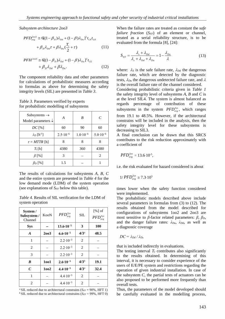
Subsystem architecture 2oo3
GECEDuDdD
oo
avg ttPFD 232 ])1()1[(6
)2
( 1 T
DuDdD (11)
CEDuDdD
oo tPFH 232 ])1()1[(6 .
DuDdD (12)
The component reliability data and other parameters
for calculations of probabilistic measures according
to formulas as above for determining the safety
integrity levels (SIL) are presented in Table 3.
Table 3. Parameters verified by experts
for probabilistic modelling of subsystems
Subsystems
Model parameters A B C
DC [%] 60 90 60
λD [h-1] 2.5∙106 1.0∙106 5.0∙106
= MTTR [h] 8 8 8
TI [h] 4380 360 4380
β [%] 3 2
βD [%] 1.5 1
The results of calculations for subsystems A, B, C
and the entire system are presented in Table 4 for the
low demand mode (LDM) of the system operation
(see explanations of SFF below this table).
Table 4. Results of SIL verification for the LDM of
system operation
System /
Subsystem /
Channel
KooN Sys
avgPFD SIL
[%] of
Sys
avgPFD
Sys 13.6∙105 3 100
A 2oo3 6.6∙105 4/3a 48.5
1 2.2∙103 2
2 2.2∙103 2
3 2.2∙103 2
B 1oo1 2.6∙105 4/3b 19.1
C 1oo2 4.4∙105 4/3a 32.4
1 4.4∙103 2
2 4.4∙103 2
a SIL reduced due to architectural constrains (SFF = 90%, HFT 1) b SIL reduced due to architectural constrains (SFF = 99%, HFT 0)
When the failure rates are treated as constant the safe
failure fraction (SFF) of an element or channel,
treated as a serial reliability structure, is to be
evaluated from the formula [8], [24]:
Du
DuDds
Dds
FFS
1
(13)
where: S is the safe failure rate, Dd the dangerous
failure rate, which are detected by the diagnostic
tests, Du the dangerous undetected failure rate, and
is the overall failure rate of the channel considered.
Considering probabilistic criteria given in Table 1
the safety integrity level of subsystems A, B and C is
at the level SIL4. The system is almost balanced as
regards percentage of contribution of these
subsystems in the system Sys
avgPFD , which ranges
from 19.1 to 48.5%. However, if the architectural
constrains will be included in the analysis, then the
safety integrity level for these subsystems is
decreasing to SIL3.
A final conclusion can be drawn that this SRCS
contributes to the risk reduction approximately with
a coefficient of
Sys
avgPFD = 13.610-5,
i.e. the risk evaluated for hazard considered is about
1/Sys
avgPFD 7.3103
times lower when the safety function considered
were implemented.
The probabilistic models described above include
several parameters in formulas from (3) to (12). The
results obtained from the model described for
configurations of subsystems 1oo2 and 2oo3 are
most sensitive to β-factor related parameters: β, βD,
and the danger failure rates: λDu, λDd, as well as
a diagnostic coverage
DC = λDd / λD,
that is included indirectly in evaluations.
The testing interval TI contributes also significantly
to the results obtained. In determining of this
interval, it is necessary to consider experience of the
users of E/E/PE system and restrictions regarding the
operation of given industrial installation. In case of
the subsystem C, the partial tests of actuators can be
also proposed to be performed more frequently than
overall tests.
Thus, the parameters of the model developed should
be carefully evaluated in the modelling process,

Kosmowski Kazimierz T.
144
considering verified sources of information, careful
aggregation of the expert opinions concerning the β
and βD factors (Table 2). In some cases, also opinions
of specialists responsible for the design of the
E/E/PE systems or SIS, and experienced engineers
supervising operation of these systems in industrial
critical installations could be useful in the
probabilistic evaluation of the safety-related systems.
The results of probabilistic modelling and the model
sensitivity analysis could be undoubtedly useful in
developing operational procedures for safety related
systems [25].
5. Cybersecurity of safety related control
systems
The security related remote attacks are becoming
increasingly important threats to the IT and OT
systems, especially the IACS operating within
industrial networks of hazardous plants [9], [12],
[16]. The internal or external threats can initiate in
the IT and/or OT security-related incidents with the
potential to adversely impact the SRCS and safety
critical installations. Their vulnerability is
understood as a security related weakness of the IT
and/or OT systems and related networks that can be
exploited by various threats to trigger hazardous
events having significant potential to make losses
[12], [21]. The cyber resilience of such systems and
networks [2] is an important issue to be adequately
treated also in the BCM [14].
A threat may be either passive or active. In case of
the passive threat the agents usually gather
information by casual communications with
employees and contractors. Examples of active
threats are as follows [12]: database injection,
spoofing and impersonation, phishing, malicious
code, Denial of Service (DoS), escalation of
privileges, physical destruction, etc. As it was
mentioned the security-related analyses should be
carefully carried out to identify the SRCS
vulnerability that can be exploited by various threats,
potentially impacting the reliability and safety of the
entire production installations.
The IT security risks shall be mitigated through the
combined efforts of component suppliers, the
machinery manufacturer, the system integrator, and
the machinery end user [11], [26]. Generally, the
potential responses to the security risks should take
following steps [12]:
eliminate the security risk by design (avoiding
vulnerabilities),
mitigate the security risk by risk reduction
measures (limiting vulnerabilities),
provide information about the residual security
risk and the measures to be adapted by the
user.
The standard IEC 62443 [11] proposes an approach
to deal systematically with the security-related issues
of the IACS. Four security levels (SLs) are defined
that are understood as a confidence measure that the
IACS is free from vulnerabilities and it functions in
an intended manner (see Table 5). In the standard
IEC 63074 [12] these levels are also proposed to deal
with the SRCS security of manufacturing systems.
The SL is related to seven foundational requirements
(FRs):
FR 1 identification and authentication
control (IAC),
FR 2 use control (UC),
FR 3 system integrity (SI),
FR 4 data confidentiality (DC),
FR 5 restricted data flow (RDF),
FR 6 timely response to events (TRE),
FR 7 resource availability (RA).
Thus, instead to express the SL as a single number, it
is suggested to apply a related vector of seven FRs
specified above. Such vector is proposed for
describing the security requirements for a zone,
conduit, component, or system. This vector may
contain the integer numbers of SL from 1 to 4 or 0 to
be assigned to consecutive FRs. A general format of
the security assurance level (SAL) to be evaluated is
defined as follows [11]:
SL-? ([FR,] domain)
= [IAC UC SI DC RDF TRE RA] (14)
where: SL-? = (required) the SL type: possible
formats are: SL-T = target SAL, SL-A = achieved
SAL, and SL-C = capabilities SAL vector;
[FR,] = (optional) field indicating the FR that SL
value applies; domain = (required) is applicable
domain that SL applies – this may be procedure,
system or component, when applying the SL
to a system; it may be for instance: Zone A,
Machinery B, Engineering Workstation, etc.
For instance, according to the standard [11] it can be
written as follows:
SL-T (Control System Zone)
= [2 2 0 1 3 1 3],
SL-C (Engineering Workstation)
= [3 3 2 3 0 0 1],
SL-C (RA, Safety PLC) = 3; in this example
only the RA component is specified, instead of
a 7-dimension SAL vector SL-C.
Thus, three type of vectors describing SLi for
consecutive FRi of the domain are distinguished:

Systems engineering approach to functional safety and cyber security of industrial critical installations
145
SL-T (target SAL) – the desired levels of
security,
SL-C (capability SAL) – the security level that
device can provide when properly configured,
SL-A (achieved SAL) – the actual level of
security of a particular device.
The SL numbers are related to a qualitative
information addressing relevant protection scope of
the domain or zone considered, for instance, for the
IACS or SRCS as its part, as presented in Table 5.
Table 5. Security levels and protection description
of the IACS domain [11]–[12]
Security
levels Description
SL 1 Protection against casual
or coincidental violation
SL 2
Protection against intentional
violation using simple means
with low resources, generic skills,
and low motivation
SL 3
Protection against intentional
violation using sophisticated means
with moderate resources, IACS
specific skills and moderate
motivation
SL 4
Protection against intentional
violation using sophisticated means
with extended resources, IACS
specific skills and high motivation
For instance, in the case of FR 1 – identification
and authentication control (IAC) – the security levels
shall be interpreted in a following way "Identify
and authenticate the SRCS users by mechanisms
against" [11]:
causal and coincidental access by unauthorized
entities (SL 1),
intentional unauthorized access by entities
using simple means (SL 2),
intentional unauthorized access by entities
using sophisticated means (SL 3),
intentional unauthorized access by entities
using sophisticated means with extended
resources (SL 4).
For improving the SRCS security it is suggested
to elaborate guidance (the instruction handbook)
for the end user that includes the following issues
[12]:
restriction of logical/physical access to the IT
systems with potential influence on safety,
for instance using internal IT systems with risk
reduction measures, such as firewalls,
antivirus tools, etc.; providing authentication
and access control mechanisms, such as card
readers, physical locks, according to
specifications of manufacturer or integrator;
disabling all unused external ports/interfaces
and services, etc.,
detection and reaction on IT-security incidents
with potential influence on safety, for instance
checking regularly means for detecting failed
IT system components or unavailable service
according to the specifications of the
machine/component manufacturer; being
responsive for vulnerabilities resulting from a
new IT security threat and potential attack,
in case of remote maintenance and service, for
instance using provided means for setting up
and ending a remote access session according
to the specifications of the component
manufacturer; using encryption means
for initiating a remote service according
to specifications of the machine/component
manufacturer; watching any remote access
session with a restriction of duration
for remote access, etc.
Such topics should be included and carefully treated
in a security information and event management
(SIEM) to be developed and used proactively
in practice according to requirements given
in ISO/IEC 27001 [17], and supported by the
information security risk management as suggested
in ISO/IEC 27005 [18]. Its specific requirements
to be formulated should include the target SAL
(SL-T) and then verified as achieved SAL (SL-A)
considering the capability SAL (SL-C) of technology
applied. Defined system requirements (SRs)
and specific requirement enhancements (REs)
for consecutive FRs to be fulfilled at relevant SLs
from 1 to 4 are specified in the IEC 62443 standard
[11] and a recent publication [26].
6. Integrated functional safety and
cybersecurity analysis and management
The IEC 62443 [11] standard consists of 14 parts.
Some of them are still in development. The main
objective of this series is to cover important topics
of the IACS security entirely. In the second edition
of the generic functional safety standard IEC 61508
[8] it is suggested to use the IEC 62443 standard
to deal with the cybersecurity issues at the design
stage and operation of the programmable
safety-related control systems. Up to now, though,
the IEC 61508 and IEC 62443 standards have been
rather loosely linked [1]. As it was mentioned,
also in case of the SRCS of manufacturing systems
there is a need to deal more systematically
with security issues, as it has been lately emphasized
[12], [26].

Kosmowski Kazimierz T.
146
It is worth to mention that the SRCS security level
to be achieved depends strongly on the quality
of an information security management system
(ISMS) established in industrial practice. The
objective of the ISMS might be also to monitor,
continuously control, maintain and, wherever
justified, improve the IT and OT security.
The IEC 62443 standard is based on general
requirements and stipulations of the ISO/IEC 17799
and ISO/IEC 27000 series, especially as regards
basic security requirements [17]. Due to complex
and dynamic internal and external conditions making
technical specifications related to the IT and OT
security solutions for implementing in industrial
practice is quite challenging.
An important task to be undertaken is the risk
evaluation and management, as it is postulated both
in ISO/IEC 27001 [17] and ISO/IEC 27005 [18].
It includes the consideration of all functional
components of the information system including the
hardware (HW) and software (SW), communication
conduits and relevant human/organizational factors,
especially those related to the IT and OT safety
and security. Opinions are expressed that the
quantitative evaluation of security-related risk is
difficult due to the complexity of the IT and OT
system and many influencing factors involved.
The credibility of such evaluation depends
on a framework adapted and availability of data,
and expert opinions concerning specific domain
to be evaluated.
Opinions are also expressed that the CIA triad
(confidentiality, integrity, availability) is a justified
order of requirements in the IT network security
analysis, but in case of the OT system a reversed
triad, namely AIC (availability, integrity,
confidentiality) is more appropriate.
As it was mentioned above the domain SAL defined
in IEC 62443 is be evaluated using the vector
of seven FRs, as explained by the formula (14).
So, there are some doubts how to match these two
kinds of requirements in the security related
analyses. It seems to reasonable that the fundamental
requirements IAC, UC, SI and TRE should be
mapped to integrity (I), RA to availability (A), and
DC, RDF to confidentiality (C) [1], [26].
Additional issue, worth to be explained in context
of the cybersecurity evaluation, is related to the
definition of seven evaluation assurance levels
(EALs) in so-called common criteria standard (IEC
15408) [16] that usually are to be applied in defining
the IT security requirements.
As it was explained above only four SLs are defined
in IEC 62443. This issue was discussed in the
publication [6], [26] in the context of generic
functional safety standard IEC 61508 [8], in which
also four SILs are distinguished (see Table 6).
So, the problem is encountered how to treat these
concepts in an integrated functional safety
and cybersecurity analysis.
In the publication [6] the correlation between SIL
and SAL is proposed as it is shown in Table 6.
Similar correlation can be proposed for the SRCS
of manufacturing systems, however remembering
that in the machinery sector the highest SIL
to be assigned to the safety-related systems is SIL 3
[10].
Table 6. Proposed correlation between SIL
and SAL [6]
Safety
integrity
level
(SIL)
Security
assurance
level (SAL)
Explanation
SIL 1 SAL 1 SAL assignment is
based on asset owner’s
assessment SIL 2 SAL 2
SIL 3
& SIL 4
SAL 3 Reserved for total
system failure
SAL 4 Reserved for loss of life
In view of the above we propose an approach
for integrated functional safety and cybersecurity
analysis based on a framework of existing concepts
and accepted models suitable to apply
the quantitative and qualitative information available,
similarly as in the knowledge based systems [22].
We start from defining the safety functions regarding
hazards and threats identified and then evaluate
required risk reduction regarding the risk criteria
defined as it was described above. It allows
to determine: the safety integrity level required SILr
according to IEC 61508 [8], or the safety integrity
level claimed SIL CL regarding IEC 62061 [10].
As it is known, the levels: the safety integrity level
required SILr (1, 2, 3 or 4) or SIL CL (1, 2 or 3) are
related to the required risk reduction with regard
to relevant individual or social risk criteria [8], [10].
For instance, the average probability of failure
on demand PFDavg is related to the risk reduction
measure as its reciprocal.
The SILr or SIL CL determined for given safety
function must be then verified using probabilistic
model of the SRCS of architecture proposed
at the design stage. Such architecture includes
generally the hardware configuration and
requirements concerning software [8]. Parallelly,
the security related evaluation is to be carried out as
it is shown in Figure 6 for cyber security evaluation.
The integrated functional safety and cyber security
analysis are repeated when justified to enable

Systems engineering approach to functional safety and cyber security of industrial critical installations
147
a rational management of the SRCS domain in life
cycle regarding the SIL and SAL.
Additional issue to be considered is associated
with expressing SAL as a single number to be
assigned to the security level achieved SL-A for
given domain, as it is outlined below the formula
(14), according to the standard IEC 62443. It would
lead to sometimes disputable requirement that the
security levels SLi would be the same for each FRi.
However, confidentiality can play in some cases
a minor role for safety related control system
and encryption of all data might lead
to complications in testing and the time response
longer than required. So generally, different levels
of SLi may be assigned to seven consecutive
elements of the FR vector.
This problem was noticed by Braband and discussed
in the publication [1]. Only in simple cases of equal
levels SLi for consecutive FRi (i from 1 to 7)
determining SAL of domain of interest (e.g. IACS) is
straightforward, for instance SAL 1 = [1 1 1 1 1 1 1].
Generally, the SLi can be different depending on the
security technology applied or FRi relevance for the
domain considered. So, he suggests using some
security profiles, for instance for zones of interest.
However, it might also lead to many profiles,
difficult for evaluation and security related decision
making.
In our earlier publications [20] it was assumed that
resulting SAL for the domain considered can be
determined based on dominant FRi and some
common sense rules, in a similar way as in the
methodology outlined in the IEC 15408 (common
criteria) [16]. In this methodology seven evaluation
assurance levels (EALs) are distinguished, related to
classes of the security assurance requirements
(SARs) and defined scope of fulfilling relevant
requirements.
Identify hazards
Select hazard category
Evaluate individual risk and
assess risk required reduction Apply the risk
model and
criteria or
defined risk
graphs
Define a safety function (SF) for
the risk mitigation / reduction
Determine performance / safety
integrity level PLr / SIL(CL)
Design the SRCS architecture,
elaborate diagnostic / test plan
procedures
Verify PL / SIL for given SRCS
that implements SF
Validate SRCS including
security architectural constrains
Indicate potential threats
Select dominant threats
Analyse the vulnerability of
IT-OT system and network
Determine FRs vector for the
target security level SL-T
Evaluate capability FRs vector
for solutions proposed (SL-C)
Determine SL-A vector / SAL
for the SRCS implementing SF
Assess the likelihood to violate
system and SF due to threats
Specify final security measures
(technical and organisational)
Integration of
the SRCS with
installation /
machine using
solutions to be
accepted by the
manufacturer,
integrator and
user
Generic /
specific data
and knowledge
bases, reports
and standards
Apply the
probabilistic
model and
specifications /
requirements
Apply rough
risk model with
regard to
influencing
factors
Repeat analyses in case of changes in the system / network / environment
Plan periodic tests and preventive maintenance in life cycle. 1
1 Functional safety evaluation Cyber security evaluation
2
2
Figure 6. Integrated functional safety and cybersecurity analysis for the SRCS domain

Kosmowski Kazimierz T.
148
We propose below another method for determining
the security level achieved SL-A (SAL) for
the domain considered if the weights wi of security
levels SLi for consecutive (and relevant) FRi are
evaluated by experts. These weights can differ
in general due to diversified importance of FRi
for the domain considered. The method includes
cases in which not all fundamental requirements FRi
are relevant to the domain considered. It is suggested
in the IEC 62443, as explained below the formula
(14). There are cases that only one relevant FRi is
relevant [11].
Thus, instead of determination of SAL for given
domain based on dominant FRi we propose
alternatively to evaluate a domain security index SIDo
and then to assign an integer number (1, 2, 3, or 4)
to the SAL as it is proposed in first column
of Table 7. The importance Ii of FRi is evaluated
by experts for specific domain, for instance
indicating an integer number on the scale from 1 to 5
(or 1 to 10), and 0 if FRi is not relevant. Then,
the weight wi of given FRi is calculated according
to following formula
.7
1
ii
i
i
I
Iw (15)
The security index SIDo for the domain (Do) and
determined security level SLi (the integer number
from 1 to 4, or 0 if FRi is not relevant) for relevant
(Re) fundamental requirements (FRi) is to be
calculated as follows
.Re
i
ii
Do SLwSI (16)
Four intervals of the domain security index SIDo
(from SIDo1 to SIDo4) are proposed in first column of
Table 7 for assigning the category number of SAL
from 1 to 4. Such approach corresponds with
attributing SAL for the domain in our earlier
publications, based on dominant SLi for relevant
fundamental requirements FRi.
Proposed correlations between security index to be
assigned to the domain SIDo or SAL and final SIL
attributing to the SRCS in hazardous installation are
presented in Table 7. It was assumed that SIL has
been verified according to IEC 61508 based
on results of probabilistic modelling as described
above, regarding CCFs and human factors,
and the architectural constrains for evaluated SFF
and HFT of consecutive subsystems.
Thus, the verification of the SIL requires
probabilistic modelling of the SRCS of proposed
architecture regarding SFF and HFT of subsystems.
In the case study as above (results in Table 4),
the safety integrity level SIL 3 was obtained.
Considering the domain of SRCS in which
the safety function is implemented including
the communication conduits, the SL-A vector was
evaluated as follows: [3 2 3 2 2 3 2]. Assuming that
weights of all SLi are equal (wi = 1/7) and using
the equation (16), the result obtained using
the formula (16) is SIDo = 2.43, to be interpreted
as SAL 2. Looking at the column 3 of Table 7
the final safety integrity level, validated regarding
the security requirements, is SIL 2, lower than
required SIL 3.
Table 7. Proposed correlation between SIDo or SAL for evaluated domain and final SIL to be attributed to the
SRCS of safety critical installation
Security index SIL verified according to IEC
61508*
SIDo / SAL 1 2 3 4
SIDo1 [1.0, 1.5) / SAL 1 SIL 1 SIL 1 SIL 1 SIL 1
SIDo2 [1.5, 2.5) / SAL 2 SIL 1 SIL 2 SIL 2 SIL 2
SIDo3 [2.5, 3.5) / SAL 3 SIL 1 SIL 2 SIL 3 SIL 3
SIDo4 [3.5, 4.0] / SAL 4 SIL 1 SIL 2 SIL 3 SIL 4
* verification includes the architectural constrains regarding SFF
and HFT of subsystems

Systems engineering approach to functional safety and cyber security of industrial critical installations
149
Therefore, the security of the domain should be
improved (its vulnerability decreased). For instance,
in case of the SL-A vector [3 3 3 3 2 3 2], SIDo = 2.71
and relevant SAL for such domain could be indicated
as SAL 3. In this case finally validated SIL will be
equal SIL 3, and the process of the SRCS
in designing may be stopped, if required SIL,
obtained from the risk assessment, SILr was also
evaluated as 3.
7. Conclusion
Traditionally, the industrial production installations
include the information technology (IT) and the
operational technology (OT). Lately, using the cloud
technology (CT) is often considered as an external
network that is more and more important for
distributed manufacturing and business management.
Advanced automation and control systems are also
in dynamic development based, for instance, on the
OPC UA and AutomationML concepts. They offer
advanced manufacturing solutions and production
flexibility. However, it causes some problems to be
solved that include the reliability, safety and security
issues, crucial also for the business continuity
management (BCM) to mitigate the risks of outages,
abnormal situations and major accidents contributing
to high losses.
Selected design and operational aspects of the OT
and IT networks have been overviewed and
discussed in this chapter in the context
of functionality and architectures of the industrial
automation and control systems (IACS) to be
designed and operated in life cycle. Emphasis was
put on the functional safety and cybersecurity
of the industrial control systems and networks. These
issues are becoming crucial, because the IACS that
includes the safety related control system (SRCS)
plays a key role in innovative high-quality
manufacturing, especially in modern industrial plants
of Industry 4.0, and safety critical industrial
installations.
In this chapter a method is proposed for integrated
functional safety and cybersecurity analysis,
regarding the concepts outlined in the generic
functional safety standard IEC 61508 (7 parts)
and the cybersecurity standard IEC 62443 (14 parts).
To limit the vulnerability of the IT and OT systems
and networks, and the SRCS to be designed
and operated to reduce relevant risks, a set
of security-related fundamental requirements (FRs)
defined in IEC 62443-1 is considered in the analyses
and evaluations.
The method proposed uses the individual
and/or societal risk graphs for determining the safety
integrity level required (SILr) of consecutive safety
functions to be defined and analysed. These levels
are then verified to indicate that the required SIL is
achievable in the designed SRCS of architecture
proposed, in which given safety function is to be
implemented.
For that purpose, relevant probabilistic models of the
SRCSs are to be developed regarding potential
common cause failures (CCFs), when a hardware
redundancy in its subsystems should be applied
to increase their dependability. Then, the verified
SIL is validated regarding determined SAL of the
domain of interest, for instance the domain of SRCS
in which safety given function is implemented,
including internal and external communications that
can be vulnerable to potential threats.
The dependability of the SRCS performing the safety
functions can be influenced both by technical factors,
including requirements concerning hardware (HW)
and software (SW), and the human and
organizational factors [22]–[23]. These aspects
require further research, especially in the context
of the design and operation of high complexity
industrial installations, including the functional
safety and cybersecurity aspects regarding
the defense in depths (D-in-D) concept and related
strategy to be elaborated and applied in particular
industrial plant.
Industrial plants are characterized by the venture
capital, production capacity, existing or emerging
hazards and threats that influence various risks
in changing environment. To deal systematically
with such challenging and interrelated issues
the systems engineering offers a general framework
to be adapted for using in life cycle of given critical
installation.
Acknowledgement
The chapter presents some results developed in the
scope of the HAZARD project that has received
funding from the Interreg Baltic Sea Region
Programme 2014–2020 under grant agreement
No #R023, and the Polish Safety and Reliability
Association supporting substantively research and
on-line attendance in the SSARS 2020 event
in Ciechocinek, as well as the Gdańsk University
of Technology, Department of Electrical and Control
Engineering, under statutory activity.
References
[1] Braband, J. 2016. What's Security level go to
do with safety integrity level? Proceedings
of 8th European Congress on Embedded Real
Time Software and Systems, hal–01289437,
Toulouse.

Kosmowski Kazimierz T.
150
[2] CISA. 2020. Assessments: Cyber Resilience
Review,
(https://us–cert.gov/resources/assessments,
accessed: Febr 2020).
[3] ENISA. 2016. Communication Network
Dependencies for ICS/SCADA Systems,
European Union Agency for Network and
Information Security.
[4] Felser, M., Rentschler, M. & Kleinberg, O.
2019. Proceedings of the IEEE Coexistence
Standardisation of Operational Technology
and Information Technology, 107(6).
[5] Gołębiewski, D. & Kosmowski, K. T. 2017.
Towards process-based management system
for oil port infrastructure in context
of insurance. Journal of Polish Safety and
Reliability Association, Summer Safety and
Reliability Seminars 8(1), 23–37.
[6] Holstein, D. K. & Singer, B. 2010. Quantitative
security measures for cyber & safety security
assurance. Presented at: ISA Safety & Security
Symposium, ISA.
[7] HSE. 2015. Cyber Security for Industrial
Automation and Control Systems, Health
and Safety Executive (HSE) Interpretation
of Current Standards on Industrial
Communication Network and System Security,
and Functional Safety.
[8] IEC 61508. 2016. Functional Safety of
Electrical/ Electronic/ Programmable
Electronic Safety-Related Systems, Parts 1–7.
International Electrotechnical Commission,
Geneva.
[9] IEC 61511. 2016. Functional Safety: Safety
Instrumented Systems for the Process Industry
Sector. Parts 1–3. International Electrotechnical
Commission, Geneva.
[10] IEC 62061. 2005. Safety of Machinery –
Functional Safety of Safety-Related Electrical,
Electronic, and Programmable Electronic
Control Systems. International Electrotechnical
Commission, Geneva.
[11] IEC 62443. 2018. Security for Industrial
Automation and Control Systems. Parts 1–14
(some parts in preparation). International
Electrotechnical Commission, Geneva.
[12] IEC 63074. 2017. Security Aspects Related to
Functional Safety of Safety-Related Control
Systems. International Electrotechnical
Commission, Geneva.
[13] IS. 2019. Industrial Security. Siemens,
siemens.com/industrial security.
[14] ISO 22301. 2012. Societal Security – Business
Continuity Management – Requirements.
International Organisation for Standardisation,
Geneva.
[15] ISO 22400. 2014. Automation Systems and
Integration – Key Performance Indicators
(KPIs) for Manufacturing Operations
Management, Parts 1 and 2. International
Organisation for Standardisation, Geneva.
[16] ISO/IEC 15408. 2009. Information Technology,
Security Techniques – Evaluation Criteria for IT
Security, Part 1–3, Geneva.
[17] ISO/IEC 27001. 2013. Information Technology
– Security Techniques – Information Security
Management Systems – Requirements, Geneva.
[18] ISO/IEC 27005. 2018. Information Technology
– Security Techniques – Information Security
Risk Management, Geneva.
[19] Kosmowski, K. T. 2006. Functional safety
concept for hazardous system and new
challenges. Journal of Loss Prevention in the
Process Industries, 19(1) 298–305.
[20] Kosmowski, K. T., Śliwiński, M. & Barnert, T.
2006. Functional safety and security assessment
of the control and protection systems. European
Safety & Reliability Conference, ESREL 2006,
Taylor & Francis Group, London.
[21] Kosmowski, K. T. 2013. Functional Safety
and Reliability Analysis Methodology for
Hazardous Industrial Plants. Gdansk University
of Technology Publishers.
[22] Kosmowski, K. T. & Śliwiński, M. 2015.
Knowledge-based functional safety and security
management in hazardous industrial plants with
emphasis on human factors. In: Advanced
Systems for Automation and Diagnostics,
PWNT, Gdańsk.
[23] Kosmowski, K. T. & Śliwiński, M. 2016.
Organizational culture as prerequisite
of proactive safety and security management in
critical infrastructure systems including
hazardous plants and ports. Journal of Polish
Safety and Reliability Association, Summer
Safety and Reliability Seminars 7(1) 133–145.
[24] Kosmowski, K. T. 2018. Safety integrity
verification issues of the control systems for
industrial power plants. In: Advanced Solutions
in Diagnostics and Fault Tolerant Control.
Springer Int. Publishing AG, 420–433.
[25] Kosmowski, K. T. & Gołębiewski, D. 2019.
Functional safety and cyber security analysis for
life cycle management of industrial control
systems in hazardous plants and oil port critical
infrastructure including insurance. Journal
of Polish Safety and Reliability Association,
Summer Safety and Reliability Seminars 10(1)
99–126.
[26] Kosmowski, K. T., Śliwiński, M. & Piesik, J.
2019. Integrated functional safety and
cybersecurity analysis method for smart
Systems engineering approach to functional safety and cyber security of industrial critical installations
151
manufacturing systems. TASK Quarterly 23(2)
1–31.
[27] Li, S. W. et al. 2017. Architecture Alignment
and Interoperability, an Industrial Internet
Consortium and Platform Industrie 4.0,
IIC:WHT:IN3:V1.0:PB:20171205.
[28] MERgE. 2016. Safety & Security,
Recommendations for Security and Safety Co-
engineering, Multi-Concerns Interactions
System Engineering ITEA2 Project No. 11011.
[29] Misra, K. B. (Ed.) 2008. Handbook of
Performability Engineering, Springer, London.
[30] SE. 2001. Systems Engineering Fundamentals.
Defense Acquisition University Press, Fort
Belvoir, Virginia 22060–5565.
[31] SESAMO. 2014. Integrated Design and
Evaluation Methodology. Security and Safety
Modelling. Artemis JU Grant Agreement, No.
2295354.
[32] Vathoopan, M. et al. 2018. AutomationML
mechatronic models as enabler of automation
systems engineering: use-case and evaluation.
Proceedings of the IEEE 23rd International
Conference on Emerging Technologies and
Factory Automation (ETFA), IEEE.

Kosmowski Kazimierz T.
152