FRANK J. SEILER RESEARCH LABORATORY
63
FRANK J. SEILER RESEARCH LABORATORY FJSRL-TR-81-0007 A TWO-DEGREE-OF-FREEDOM OSCILLATOR FOR JULY 1981 UNSTEADY AERODYNAf•H CS APPLICATIONS OTIC · PRELIMINARY REPORT SELECTED : AUG 0 3 1981 :. . .. _.!"\ . PROJECT 2307 E CAPT M.S. FRANCIS CAPT J.E. KEESEE f1AJ J.P. JR. APPROVED FOR PUBLIC RELEASE; DISTRIBUTION UNLIMITED. AIR FORCE SYSTEMS COMMAND UNITED STATES AIR FORCE 81 7 31 0 66
Transcript of FRANK J. SEILER RESEARCH LABORATORY

LEVEl~ @) FRANK J. SEILER RESEARCH LABORATORY
FJSRL-TR-81-0007
A TWO-DEGREE-OF-FREEDOM OSCILLATOR FOR
JULY 1981
UNSTEADY AERODYNAf•H CS APPLICATIONS
OTIC · PRELIMINARY REPORT SELECTED:
AUG 0 3 1981 :. ... _.!"\ .
PROJECT 2307
E CAPT M.S. FRANCIS CAPT J.E. KEESEE f1AJ J.P. RETELLE~ JR.
APPROVED FOR PUBLIC RELEASE;
DISTRIBUTION UNLIMITED.
AIR FORCE SYSTEMS COMMAND
UNITED STATES AIR FORCE
81 7 31 0 66

FJSRL-TR-81-O007
This document was prepared by the Mechanics Division, Directorate of
Aerospace-Mechanics Sciences, Frank J. Seiler Research Laboratory, United
States Air Force Academy, Colorado. The research was conducted under ProjectWork Unit Number 2307-Fl-36, An Investigation of Unsteady Vortex Entrapment on
an Airfoil. Major John P. Retelle, Jr. was the Principal Investigator in
charge of the work.
When U.S. Government drawings, specifications or other data are used for
any purpose other than a definitely related Government procurement opera-tion, the Government thereby incurs no responsibility nor any obligationwhatsoever, and the fact that the Government may have formulated, furnished orin any way supplied the said drawings, specifications or other data is not tobe regarded by implication or otherwise, as in any manner licensing the holderor any other person or corporation or conveying any rights or permission tomanufacture, use or sell any patented invention that may in any way be relatedthereto.
Inquiries concerning the technical content of this document should beaddressed to the Frank J. Seiler Research Laboratory (AFSC), FJSRL/NH, USAFAcademy, Colorado 80840. Phone AC 303-472-3122.
This report has been reviewed by the Commander and is releasable to theNational Technical Information Service (NTIS). At NTIS it will be availableto the general public, including foreign nations.
This technical report has been reviewed and is approved for publication.
JOHN.V RETELLE,i., Major, USAF THEODORE T. SAITO, Lt. Col, USAFPrincipal Investigator Director
Aerospace-Mechanics Sciences
WILLIAM D. SIURU, JR., Lt Col,Commander
Copies of this report should not be returned unless return is required bysecurity considerations, contractual obligations, or notice on a specificdocument.
Printed in the United States of America. Qualified requestors may obtainadditional copies from the Defense Documentation Center. All others shouldapply to. National Technical Information Service
5285 Port Royal Road
Springfield, Virginia 22161

--
\
READ INSTRUCTIONS ~--~~~~lm~r-~-.--~~------~----~~~rAcc~S!ON!w~rr.~~B~E~F;O~R~E~C;O~MPLETINGFORM
NAME AND ADDRESS
Frank J • . Seiler Research Laboratory (AFSC) USAF Academy, CO 80840
I I. CONTROLLING OFFICE NAME AND ADDRESS
Frank J. Seiler Research La boratory (AFSC) USAF Academy, CO 80840
V ERED
8 . CONTRAC T OR GRANT NUMBER(s)
--- --
NUMBER OF AGES
62 15. SEC URITY CL ASS. (o/ thl• r<'po r t)
UNCLASSIFIED ~ I Sit. DECLASSIFICATI ON; DOWN GRADIN G
SCHEDULE
16. DISTRI BU TION ST A TEMENT
Approved for public release; d istribu tion unlimited.
17. DISTRIBUTION STATEMENT (o / th<> itb•tr~tct ent<'"'d In Block 20, I I <!liferent /rom Report)
18. SUPPLEMENTARY NOTES
19. KEY WORDS (Continue on reverae si de 1; nec,.&&ary tJnd l dt>nt l/y by block number)
Unsteady flow Oscillating flow Dynamic stall Wind tunnel Computer control
ZO. ABSTRACT (Conl/nufO on reverae .•Ide If nece•sary and Iden tify bJ• bloc k number)
Numerous wind tunnel studies of airfoi l dynamic stall have been l i mited to harmonic model oscillations, but new microcomputers and hybrid servo systems have now been explo i t ed to produce a mechanism which provides a high degree of flexibility in achieving arbitrary model mot ions in mu l t i ple degree s of f r eedom over a wide range of motion alter natives. A prototype apparatus has fabricated to provide simultaneous motions of an airfoil or wing model pitch and translation. Drive motors pr ovide independent mot i on two
DO FORM I JAN 73 1473 EDITION OF 1 NOV 6 5 IS OFISOL ET E
7 I
\
UNCLASSIFIED SKCU .. tTY CLASSIFICATION OF THIS PAGE(lnlen Data Ente..ct)
Item 20 continued. under the control of servo-translator units which res pond to pulse trains generated by the microcomputer , using analog position and f eed bac k l oops t o smooth the pul ses. Programs are developed in a higher-l evel l anguage u sing a larger disk-based computer system and then t he program t ask image is downline-loaded through a network communicatio~s link to the smal ler computer. In addition to a thorough description of the ex pe rimenta l apparatus, the various elements of mot ion control, i ncluding s e r vo- t ranslator dynamic characteristics . sof twar e technique s for pul se trajn generation , and required computer interf ace circuitry a re discussed. Measurements of constant rate, constant accele ration, and pu~e harmonic motivns are examined fo r bo t h drive Bxes over the e ntire ranse of drive parameter s ~
\
UNCLASSIFIED 'iECv RITY CL ASSIFICATIO. OF To .. ,.r PAGE(1t'Pien D11ra Ent~red)
TABLE OF CONTENTS
CHAPTER PAGE
I. INTRODUCTION I
I1. MECHANICAL DESIGN 3
A. MOTION TRANSFER APPARATUS 3
B. PITCH DRIVE ASSEMBLY 3
C. MODEL AND MODEL INTERFACE 6
D. TRANSLATIONAL DRIVE ASSEMBLY 7
E. FACILITY INTERFACE 8
III. SERVO-DRIVE ELECTRONICS 10
IV. COMPUTER COMMAND SYSTEM 14
A. PULSE TRAIN REQUIREMENTS 14
B. HARDWARE 15
C. SOFTWARE 17
V. PERFOR.MANCE 20
VI. SUMMARY AocOesi~n For 25SNTIS .1GIA i
REFERENCES DTIC TAB 26Ujannounc(,c [ ]
ACKNOWLDGEMENTS Jut ifiction- 27
FIGURES 28
jstribution/ ..
AvailabilitY Codes
AvaiL andI/orDist Special.
1' I
LIST OF F IGURES
TITLE
1 Two-l.>egre e- o f-Freedom Apparatus, Functi ona l Schematic
2 Mechanical Oscillation Assembly
3 Pitch Yoke Sub-Assembly
4 SM708 Series Motor - Description
Model Mounti ng Detail 5
6 NACA 001 2 Ai r f o i l Mod e l a nd Instrumentation
7 Translational Drive Assembly
8 Expe riment Installed in USAFA 2 ft x 3 f t Subsonic Wind Tunnel
9 Neoprene Slot Se a l
10 Servo Drive Electroni cs - Schem~ t· c
11 Servo Translator Conce pt
12 Pitch Drive Control System- Functional Schematic
13 Pitch Drive Control Electronics - Interconnection Diagram
14 Translational Drive Control System - Functional Schematic
15 Translationa l Drive Control System - Interconnection Diagram
16 Relay Interface Circuit - Schematic
17 Microcompute r Int t: r f ace Circuit - Single Channe l Sc hemat i c
18 Selection of Mo t or Characteristics
19 Position Poteniome l~ r Amplified Circuit
ii
..

LIST OF FIGURES (CONTINUED)
TITLE
20 Pitch Oscillator Performance, Constant Rate Motion, Low to Moderate
Frequencies
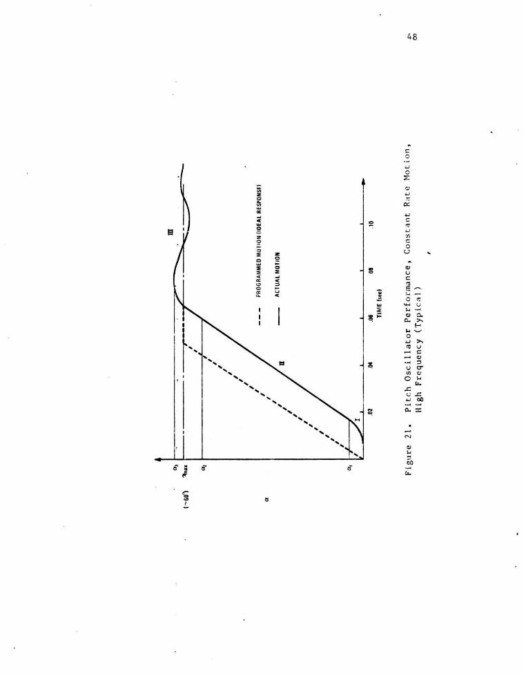
21 Pitch Oscillator Performance, Constant Rate Motion, High Frequency(Typical)
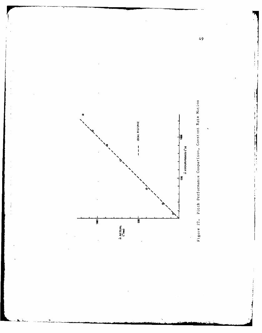
22 Pitch Performance Comparison, Constant Rate Motion
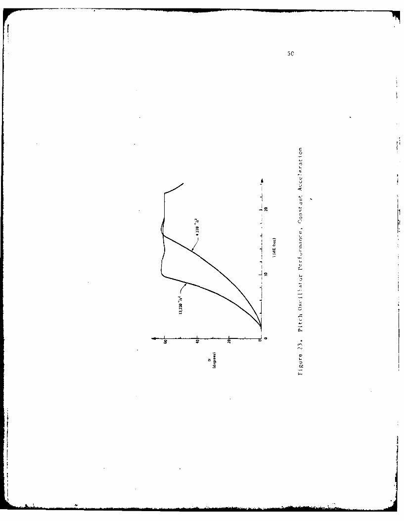
23 Pitch Oscillation Performance, Constant Acceleration
24 Pitch Performance Comparison, Constant Acceleration
25 Translational Oscillator Performance, Constant Rate Motion
26 Translational Drive Performance - Tunnel Off, Constant Rate Motion
27 Translational Drive Performance - Tunnel Off, Constant Acceleration
Performance
28 Combined Drive Performance - Illustration at High Frequency
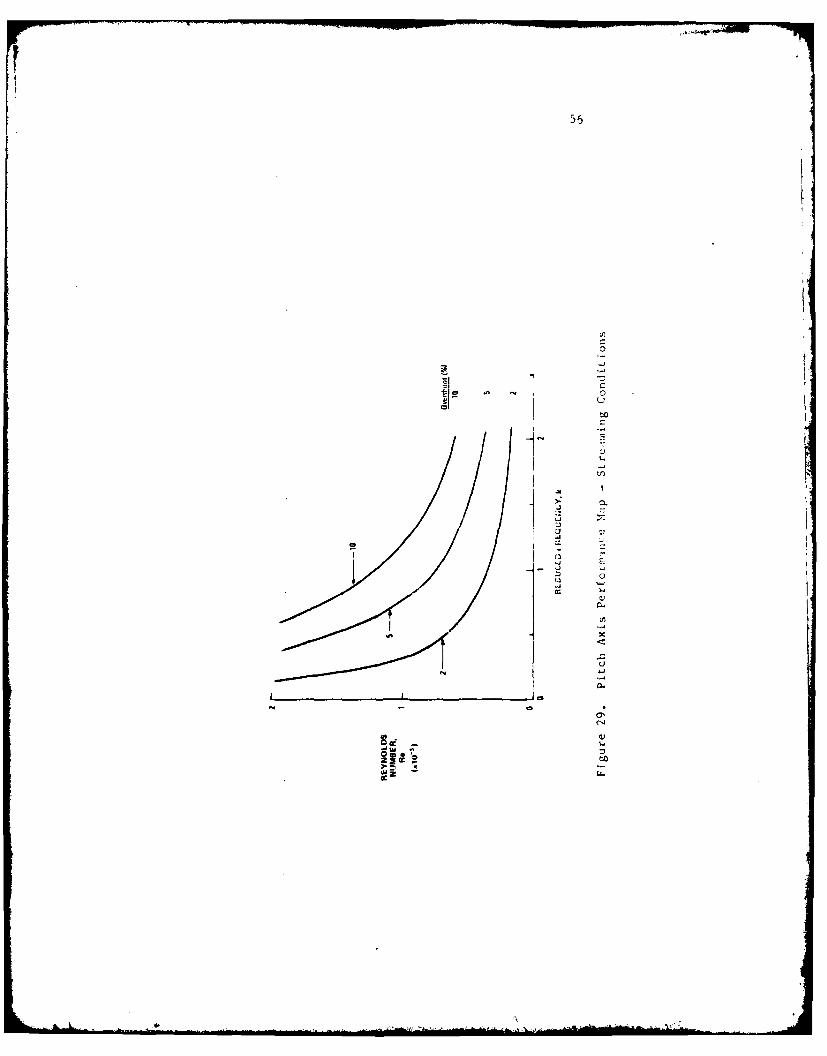
29 Pitch Axis Performance Map - Streaming Conditions
iii

I. Introduction
Recent interest in the complex flow separation phenomena which have been
observed to accompany airfoil dynamic stall has precipitated a requirement to
generate arbitrary but controlled model motions in the laboratory environment.
Numerous previous research efforts (e.g •• see References 1-5) have been
limited to examining the e~fects of nominally harmonic (sinusoidal) oscilla
tions due. in part. to the complexity involved in the design and fabrication
of a more general purpose device. Recent improvements in the response
characteristics of advance9 hybrid servo systems and. independently. the
development of the low cost microcomputer for control applications have oeen
exploited to produce a mechanism which possesses heretofore unrealized
flexibility in achieving a wide range of motion alternatives.
This report describes and discusses the design and operation of a f>'roto
type. multi-purpose oscillation apparatus capable of providing simultaneous,
independent motions of an ai~foil (or other) model in two degrees of freedom.
In combination with the measurement techniques discussed later, the concept
affords a high degree of cycle-to-cycle repeatability and a potential to
generate any of a virtually infinite variety of simultaneous complex motions
in both rotation and trans'lation.
The specific system was designed and constructed for advanced dynamic
stall studies at the Frank J. Seiler Research Laboratory and permitted
controlled repetitive motions of several small airfoil models (6- to 8-inch
chord) in both pitch and translation. Depending on the orientation of t he
test apparatus. translational motion could be produced it. either the f ree
stream or cross-stream directions. The entire apparatus was located adjacent
to and just outside of the 2 ft x 3 ft subsonic wind tunnel test section
allowing only the model to be exposed to the air stream through a slot in the
test section floor.
The oscillator system i.s functionally composed of f our e lements : (1) t he
Motion Transfer Apparatus, (2) the Model and its interface collar, (3) Dual
Hybrid Servo Drive Units ~nd (4) a Microcomputer Control System. These
elements are depicted sche~atically in Figure 1. The Motion Transfer
Apparatus is a de~ice constructed from aluminum and steel components which
serves to transform shaft displacements from the d~ive motors to desired
model motions. The model is fastened to this apparatus through a coupling on
the rotational (pitch) drive yoke. The Servo Drive Units are complex feed
back controlled positioning systems capable of accurate instantaneous rate
control which independently provide power to the Motion Transfer Apparatus in
both degrees of f reedom. Pulse width modulation techniques are employed in
these units to maximize power transfer rate and, therefore, optimize overall
system response. The Microcomputer Control System provides a preprogrammed
series of pulses to the Servo Drive Units which then effect the desired
displacements. Both units are simultaneously controlled by the same micro
computer CPU.
Each of the elements briefly described above is the subject of a separate
section of this report. While these elements and their integration remain the
primary focus of this document, the role of the entire mechanism in the over
all experimental arrangement is also addressed, especially its relat i onship to
the host data acquisition minicomputer which functions as the experiment's
central control manager . The performance characteristics of the overali
system when subjected to various test conditior.s are also discussed.
2

3
II. Mechanical Design
A. Motion Transfer Apparatus
Perhaps the least complex of the sub-systems mentioned in the preceding
section is the Motion Transfer Apparatus - a mechanical assembly which
transfers kinetic energy from the drive motors to the wind tunnel model.
This device consists of an aluminum frame on which the various drive train
components are mounted and interconnected. The entire assembly is supported
by a steel mainframe fabricated from heavy gauge angle sections and provided
with casters for portability when not in use. During operation, the unit is ..
loc~ted outside of and below the wind tunnel test section so that only the
model protrudes into the a:f.rstream. The complo!te apparatus is depicted in
Figure 2.
The drive system is configured in a dual yoke arrangement which provides
uncoupled motions in rotation (pitching motion, in this case) and translation.
The pitch drive assembly, including the pitch motor, is "piggy-backed" on the
translational drive unit. In this configuration, a much lower power require-
ment results for the pitch drive motor compared to the translational drive
unit. ·Both drives are designed to provide minimal mechanical amplificat i or.
factors for maximum dynamic response.
B. Pitch Drive Ass~~bly
Rotational, or pitch, motion is generated through the pitch yoke su~-
assembly which is depicted schematically in Figure 3. Angular Gisplacement
of the drive motor shaft is first converted to linear displacement of the
yoke assembly through a coupler device which conn~cts the motor flywheel to
the yoke cross-rod through a ball bushing encasement which is free to slide
along the cross-rod. A cylindrical bearing mounted in the coupler device is
mated to an interconnecting pin which protrudes from an off-cent~! ~ocation
4
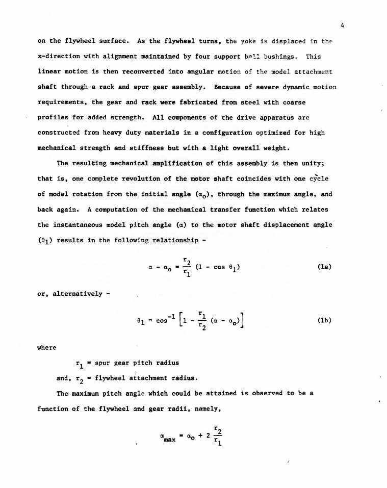
on the flywheel surface. As the flywheel turns. the yoke i s displaced i n the
x-direction with alignment maintained by four support b~!! bushings. This
linear motion is then reconverted into angular motion of the model attachment
shaft through a rack and spur gear assembly. Because of severe dynamic moti on
requirements, the gear and rack were fabricated from steel with coarse
profiles for added strength. All components of the drive apparatus are
constructed from heavy duty materials in a configuration optimized for high
mechanical strength and stiffness but with a light overall weight.
The resulting mechanical amplification of this assembly is then unity;
that is. one complete revolution of the motor shaft coincides with one cycle
of model rotation from the. initial angle (a0 ). through the maximum angle, and
back again. A computation of the mechanical transfer function which relates
the instantaneous model pftch angle (a) to the motor shaft displacement angle
(el) results in the following relati onship -
(la)
or. alternatively -
(lb)
where
r1 • spur gear pitch radius
and. r 2 • flywheel attachment radius.
The maximum pitch angle which could be attained is observed to be a
function of the flywheel and gear radii. namely,
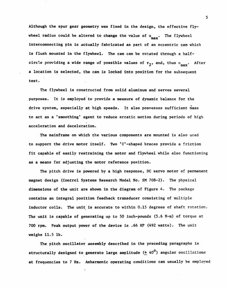
Although the spur gear geometry was fixed in the design, the effective fly-
wheel radius could be altered to change the value of a • The flywheel . max
interconnecting pin is actually fabricated as part of an eccentric cam which
is flush mounted in the flywheel. The cam can be rotated through a half-
circle providing a wide r~nge of possible values of r 2, and, thus a max After
a location is selected, the cam is locked into position for the subsequent
test.
The flywheel is constructed from solid aluminum and serves several
purposes. It is employed to provide a measure of dynamic balance for the
drive system, especially at high speeds. It also pos~esses sufficient mass
to act as a 'smoothing' agent to reduce erratic motion during periods of high
acceleration and deceleration.
The mainframe on which the various components are mounted is also used
to support the drive motor itself. Two 'U'-shaped braces provide a friction
5
fit capable of easily restraining the motor and flywheel while also functioning
as a means for adjusting the motor reference position.
The pitch drive is powered by a high response, DC servo motor of permanent
magnet design (Control Systems Research Model No. SM 708-2). The physical
dimensions of the unit are shown in the diagram of Figure 4. The package
contains an integral position feedback transducer consisting of multiple
inductor coils. The unit. is accurate to within 0.15 degrees of shaft rotation.
The unit is capable of generating up to 50 inch-pounds (5.6 N-m) of torque at
700 rpm. Peak output power of the device is .66 HP (492 watts). The unit
weighs 11.5 lb.
The pitch oscillator assembly described in the preceding paragraphs is
structurally designed to generate large amplitude (± 40°) angular oscillations
at frequencies to 7 Hz. Anharmonic operating conditions can usually be employed
6
to provide less severe loa~ing at even higher instantaneous rotation r ates -
a subject which is discussed below.
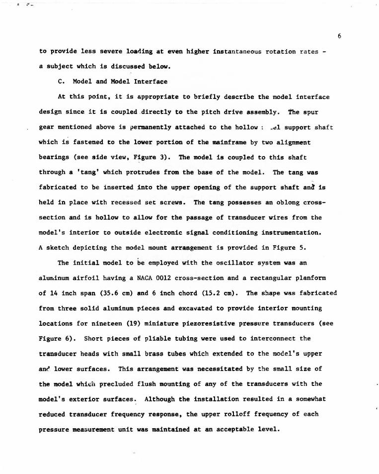
C. Model and Model Interface
At this point, it is appropriate to briefly describe the model interface
design since it is coupled .directly to the pitch drive assembly. the spur
gear mentioned above is permanently attached to the hollow ~~1 support shaft
which is fastened to the lower portion of the mainframe by two alignment
bearings (see side view, Figure 3). The model is coupled to this shaft
through a 'tang' which protrudes from the base of the model. The tang was ~
fabricated to be inserted ~nto the upper opening of the support shaft ana is
held in place with recessed set screws. The tang possesses an oblong cross-
section and is hollow to allow for the passage of transducer wires from the
model's interior to outside electronic signal conditioning instrumentation.
A sketch depicting the model mount arrangement is provided in Figure 5.
The initial model to be employed with the oscillator system was an
aluu.inum airfoil having a NACA 0012 cross-section and a rectangular planform
of 14 inch span (35.6 em) and 6 inch chord (15.2 em). The snape was fabricated
from three solid aluminum pieces and excavated to provide interior mounting
locations for nineteen (19) miniature piezoresistive pressure transducers (see
Figure 6). Short pieces of pliable tubing were used to interconnect the
transducer heads with small brass tubes which extended to the model's upper
an~ lower surfaces. This arrangement was necessitated by the small size of
the model whicu precluded flush mounting of any of the transducers with the
model's exterior surfaces. Although the installation resulted in a somewhat
reduced transducer frequency response, the upper rolloff frequency of each
pressure measurement unit was maintained at an acceptable level.
7
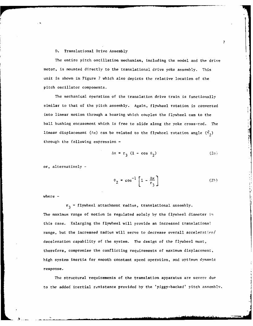
D. Translational Drive Assembly
The entire pitch oscillation mechanism, including the model and the drive
motor, is mounted directly to the translational drive yoke assembly. This
unit is shown in Figure 7 which also depicts the relative location of the
pitch oscillator components.
The mechanical operation of the translation drive train is functionally
similar to that of the pitch assembly. Again, flywheel rotation is converted
into linear motion through a bearing which couples the flywheel cam to the
ball bushing encasement which is free to slide along the yoke cross-rod. The
linear displacement (Ax) can be related to the flywheel rotation angle 4-2
through the following expression-
Ax r3 (1-cosO2 ) (2a),
or, alternatively-
(lcos l kx (2b)
where-
r flywheel attachment radius, translational assembly.
The maximum range of motion is regulated solely by the flywheel diameter in
this case. Enlarging the flywheel will provide an increased translational
range, but the increased radius will serve to decrease overall acceleration/
deceleration capability of the system. The design of the flywheel must,
therefore, compromise the conflicting requirements of maximum displacement,
high system inertia for smooth constant speed operation, and optimum dynamic
response.
The structural requirements of the translation apparatus are severe due
to the added inertial resistance provided by the 'piggy-backed' pitch assemblv.

As a result, much larger components were used in the cons truction of t his unit
including, for example, one-inch diameter rods to support the yoke frame.
Every effort was made during the initial design and f abrication to minimize
the weight of the moving asb~~~ly without compromising requisite structural
integrity. The net mass of the complete translational yoke and pitch assembly
after all modifications were completed was fixed at 24.9 kg (55 lb) with the
NACA 0012 airfoil model installed.
An obvious consequence of the dual yoke design approach described above
is the large power requirement for the translational drive stage compared to
that for the pitch mechanics. The mechanical performance requirements were
ambitiously defined to provide a capability for large amplitude translational
oscillations (12 inches, total travel) at a high steady state frequency (3Hz).
The resulting structural design was thought to strike a good balance between
maximized performance goals and necessary safety considerations.
To obtain reasonable dynamic performance, a 5 HP, DC motor (Ll86AT frame)
is employed with a regenerative drive power source (Control Systems Research,
"Systrol" Model 4200AP). The maximum motor speed is rated at 1750 rpm. 1o
provide necessary torque over the desired operating range, a 10:1 gear reduc
tion stage (Morse, Model ~5GCV10) is coupled between the motor drive shaft and
the flywheel.
E. Facility Interface
The combined drive assemblies are mounted on a rigid steel frame which i s
braced with heavy cross members for added stiffness. Four retractable legs
constructed from heavy steel angle sections with welded steel 'feet' are
anchored to the concrete floor beneath the wind tunnel during operation.
When not in use, the entire structure can be removed on its four heavy duty
casters by retracting the legs while the frame is supported by jacks. The
8

mainframe also serves as the primary support for the translational drive motor
and gearbox.
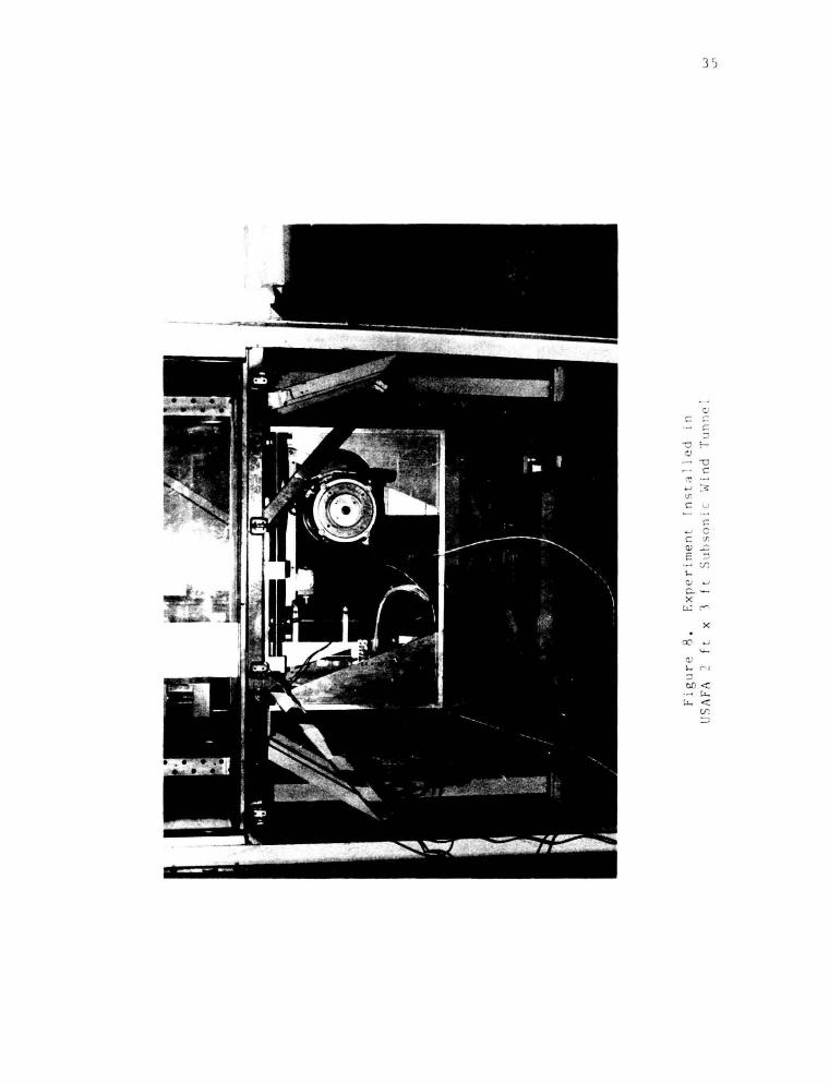
Available access to the wind tunnel test section is severely limi ted
restricting the range of possible model mounting schemes. It was for these
reasons that the apparatus was designed to provide a model attachment p.,int
through a removable portion of the test section floor (Figure 8).
The model attachment shaft coupled to th~ pitch drive assembly protrudes
into the test section through a slot which is cut in the removable floor
panel. The slot is oriented in the freestream direction and is of sufficient
length to accommodate the maximum extent of translational motion in that'
direction. It should be noted that the oscillation mechanism was designed to
alternatively permit "plu.tging" motions by rotat i ng the entire apparatus
through 90 degrees. In that case, a new floor panel with a slot orthogonal
to the freestream direction would have to be constructed.
To prevent leakage .near the base of the model and over the remainder of
the slotted region, a two~piece neoprene seal was developed. Shown in cross
section in Figure 9, the two stiffened strips of material were overlapped t o
form a "V"-configuration which was self-sealing except at t he model suppor t
shaft entrance point. Th~ material stiffness was varied on a t rial and er ror
basis to provide the best seal around the model support shaft wi thout sacr i
ficing performance in th~ open groove region. To prevent possible eff ec t s of
leakage during actual model tests, and to isolate the airfoil from unwanted
wind tunnel wall boundary layer effects, plexiglass endplates were devised
for use with the airfoil model described above.
9
III. Servo-Drive Electronics
The selection of a suitable drive concept to power the two oscillator
stages was severely impacted by two demanding performance r equirements,
namely, (1) maximization of system dynamic response, and (2) the selectable
variation of the time histories of the motion parameters, a (t) and x(t).
The first of these is attainable through the application of closed loop
control techniques. The latter requirement, it was believed, could best be
satisfied through the use of real time computer control. Ultimately, both
req~irements were met through th~ implementation of these concepts using a
device known as a "servo-translator." ..
10
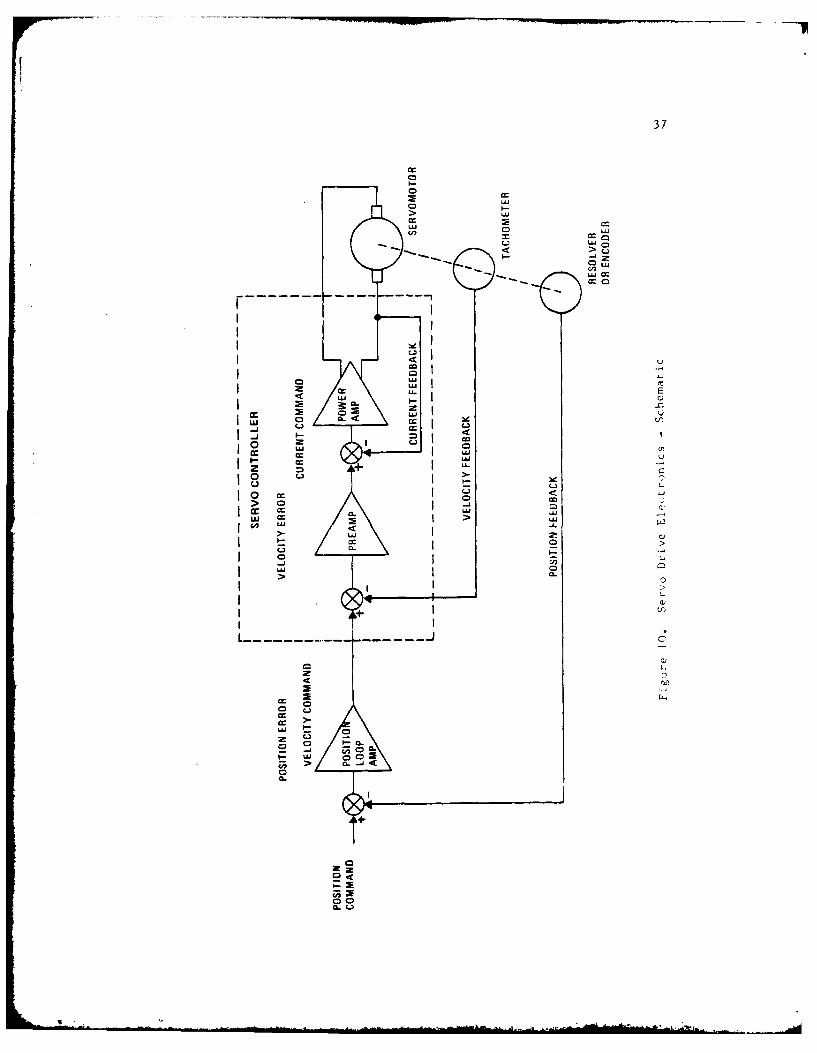
It is useful to briefly ~iscuss the operation of a servo system which
utilizes both velocity and position feedback. Such a mechanism i s shown
schematically in Figure 10. As shown, the input voltage to the servo
controller is a "velocity co1!11!1D.nd" which is ins tantaneously and continuously
compared to the velocity [ eedback signal (tachometer voltage). The difference,
the velocity-error voltage, is greatly amplified by the preamplifier and
applied ~o the power amplifier to command motor current. The current
generates torque, which , in turn, alters the motor speed to reduce the
velocity error voltage . Thus, the servo-controller is always tryi ng t o
reduce the velocity error t o zero.
The position feedback loop controls the position in the same manner that
the servo-controller controls speed. A position command generated by an
external source is compared with the position feedback signal provided by a
linear feedback transducer sensitive to position. The difference, or position
error signal, is amplified to generate the velocity command.
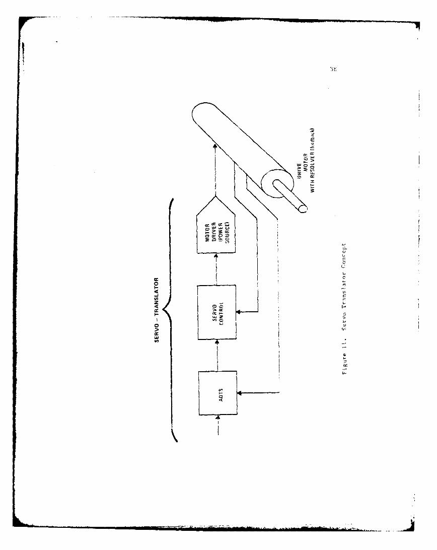
The "servo-translator, " mentioned p·,, w iously, is a device similar to the
one just discussed which employs both velocity and position feedback to

provide accurate motion control. The significant difference is the unique
design of the input stage which is shown schematically in Figure 11. Closed
loop position control is provided by a device termed an Absolute Digital
Translator Subtractor* (ADTS) which accepts command information in the form
of serial data pulses. Pulse information is compared with a feedback signal
from a non-pulse counting type of transducer (a resolver) to close the loop.
This design increases noise immunity since the requirement for encoders or
other pulse counting feedback circuits is eliminated. Errors due to
'accumulation' associated with these techniques are also eliminated.
The operating system which results is controlled in real time by th e
incoming command pulse train. Each pulse received will cause the motor to
move one increment in the selected direction, and the rate at which tlhe pule-
are received determines the instantaneous motor speed. The resolution, or
size of an angular increment, is regulated in the design of the ADTS stage
in the servo-translator. Input pulses can be generated through a number of
techniques including the output of a digital computer.
It is instructive to briefly discuss the operation of the "resol\er" -
an analog position transducer employed in conjunction with the ADTS. The
unit is brushless and utilizes a rotary transformer principle. It contains
three (3) inductive elements- windings labeled as (a) Reference, (b) Sine,
and (c) Cosine. The reference winding is located on the rotary portion (Rotor)
of the resolver while the Sine and Cosine windings are located on the stationary
section (Stator). The Reference winding is excited with a 2.5 kHz sinusoidal
reference signal provided from the servo-translator unit. With different
positions of the rotor, the Sine and Cosine windings will exhibit different
*Patent Applied For, Control Systems Research Corporation.
I

12
coupling factors. The Sine and Cosine signals are fed into the ADTS which
generates a digital command signal proportional to the sine of the difference
between the command angle and the actual Resolver (position transducer shaft)
angle.
The diverse power require~~nts of the two oscillator stages governed the
selection of the type of power amplifier employed in the two cases. A dual-
state, pulse width modulation (PWM) technique is used to provide rapid power
transfer to the pitc~l drive motor. A discussion of this concept anci i ts
advantages in high speed applications can be found in Reference 6. Because
.. of its substantially larger size and capacity, the translation drive motor
is equipped with a more conventional SCR power supply (Control Systems
Research, Systrol Model 4200AP).
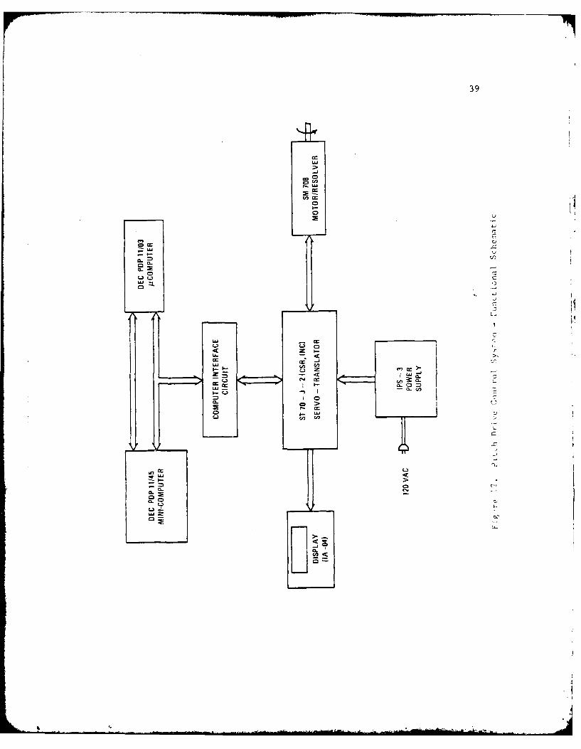
A complete schematic of the pitch drive electronics including computer
control elements is provided in Figure 12 . A de tailed interconnection
diagram is shown in Figure 13. The CSR Model ST-70J-2 Servo Translator is
the heart of the closed l ·:>Op system. The unit i.s equipped with a resolution
of 1000 steps per revolution which equates to a motor displacement resolution
of 0.36 degrees or. a mcdel pitch angle resolution of 0.21 degrees i n the worst
case with maximum amplitude cam adjustment. This factor provided for maximum
resolution and "smoothing" of motion at high speeds consistent with the
maximum output pulse rate capability of the ~omputer. A digit al display
module (CSR Model IA-04) is coupled directly to the servo-translator to
monitor displacement repeatability and possible ~rrors incurred from randomly
dropped bits. The IPS-3 direct current power supply provides power to the
drive motor through the servo power amplifier card. This unit is rated to
deliver 15 amps continuous or 45 amps peak during normal operation.
The translational drive electronics are depicted schematically in Figure 1
14 with a detailed interconnection diagram provided in Figure 15. The system
is functionally similar except for the power source. A relay interface panel
(shown in detail in Figure 16) is required to provide proper sequencing of
field and armature signals during power up and power down operations. Addi-
tional "enable" circuits are provided for added safety during the operation of
this high power system. Note that the resolver is located on the output shaft
of the gearbox. The resolution of the translational stage is set at 2500
steps per flywheel revolution providing 0.015 inches maximum resolution in
unidirectional linear travel with the cam adjusted for maximum travel.
A common feature of both drive systems is a limited capability for 'front
panel' control which is hard-wired and does not require a separate computer.
The rotation direction can be altered by a polarity control on the panel. A
constant rate puls. train-provided by an internal oscillator in the servo
translator and whose level is regulated by a potentiometer can be employed to
'JOG' the system during installation, alignm~ent and during servo system tuning.
The 'HOME' position is a designated reference location for each resolver
determined by the alignment of Its rotor and stator. This position is adju',tee,
by rotating the resolver case to any desired preset value. A 'GO HOME'
command provided through a separate pulse input can be generated either from
the computer or front panel to return the system to the reference posit-on at
the 'JOG' speed.
Only the serial data pulse inputs and respective 'GO HOME' commands hiave
been implemented through computer control in the present configuration.

14
IV. Computer Command System
A. Pulse Train Requirements
The choice of a suitable motion control computer was dict a t ed primarily
by the nature of the pulse train which must be produced as an input for the
servo-translator. In the present case, this choice was also af f ected by the
necessity to produce two independent drive signals simultaneously. An addi-
tional factor which complicated the pulse rate requirement was the non-linear
charact~r of the mechanical transfer functions (equations (1) and (2) ).
For a given drive system, the net number of pulses applied for unidirec
tional motion can be related to the flywheel angular displacement as follows -
n = K • 60 ( 3)
where -
n = number of pulses generated
K 'resolution' of the system (steps per degree )
At this point, it is useful to discuss t he concep t of 'HOME' or zero reference
position. This location i s found when t he resolver shaft and stator are
aligned to produce a 'null' reference signal. If the home position of the
resolver is aligned with the x-axis (Figure 4 or 7), the displacement angle,
AS, is equi valent t o the abs olute angl e , e. Si nce, realis tically , ther e is
always son1e degree of misalignment, it is appropriate to replace the angle
(a1 or e2
) in equations (1 ) and (2) wi th an expression wh "ch incl udes the
reference offset angle, 0 , namely -r
whP.re -
i • index, denotes the appropriate stage .
(4)
15
The pulse rate can be computed easily from equation (3) as -
dn K 5n - K6 (5)
dt s
For the pitch drive assembly, this can be expanded to obtain -
nr(t) = K (t)r2 sin [ 1sl(t) + 9r1 ] (6)
The corresponding expression for the translational drive system is
calculated as -
1 (t)n 2(t) = K2 r3 sin [es(t) + 9r2 ]
Examination of these relationships reveals, for example, that harmonic
motion of either drive output (a, or x) can be generated with a constant
pulse rate (n). To generate a rampwise behavior in time, e.g., c or x is a
constant, requires a non-linear pulse generation scheme.
It should be noted that since the control pulse trains are to be
provided through computer software, provision must also be made in programs
for acceleration and deceleration control so as not to exceed drive hardware
limitations. This is especially important when rapid motion is require,'. and
when operating near 'HOME' or its complement, i.e., when -
8 + 0 - 0 or n7
At the extrema of the cycle, infinite pulse rates are required to maintain
constant rate model motions.
B. Hardware
To produce the dual pulse trains required for simultaneous operation of
the drive systems, a Digital Equipment Corporation PDP 11/03 microcomnvter
was chosen for dedicated motion control. The unit was configured with, ?2
II

k-bytes random access memory which provided overhead {ope ra t ing sys t em) and
program support.
16
Control of the two motor drive systems was i mpl emented through a s ingl e
digital output port using select pins for the various pulse and voltage level
command functions {see Figures 13 and 15). Pulses were generated by momentary
"toggling" of th~ voltage at the appropriate output register pin from the l o\ ..
to high state. The timing of the pulses for each control channel was accom
plished in software by indexing a 'pointer' through a binary array . Each bit
is examined by software as the pointer reaches it resulting in a toggle
command to the appropriate output port if a "1" is de t ected . Bits set t'O " O"
are ignored. Succeed i ng bits are examined alt ernately f r om t he t wo arrays
which determine pi tch and translational motion. The pointer indexing r ate i s
regulated by the internal computer instruction clock, and, in this manner, a
pulse train having a pr esc ribed time his t or y, n(t), can be genera ted program
matically .
Other register pins can be employed t o control other e lements of model
motion using voltage level variations. For example, the directi on of motor
rotation could have been changed through a software command to a preselected
output pin. This option has not been exercis ed in the present case, however.
Resulting motion is t hen a single cycle pattern whi ch can be r epeated as
many times as required by relocating the poi nter to t he t op of t he arrays and
restarting the sequencing program.
Due to the high noi se environment and long control cables used in the
experiment, a two-channel, i nterface circuit was ins talled near the servo
translator input to perform pulse shaping and timing regulation. The schemati c
diagram for a single channel is provided in Figure 17. The DM74121 monostable
multivibrator chips are used to provide 'clean' pulses exhi biting rapid r ise/
17
fall rates (less than 1.0 vsec) and of precise duration (pulse width 10 Wsec,
minimum detectable is 5 wsec). The DM7416 Hex Inverter module is employed to
interface complimentary logic schemes of the computer output and servo-
translator electronics.
Although the microcomputer system described above was adequate for motion
control, the limited memory and lack of storage peripherals severely restricted
its use for program development. Since a larger, minicomputer system was
available for overall experimental control and data acquisition, a capability
was developed to interface the larger machine with the smaller one for trans-
ferring task images using a 'down-line load' technique. This simple network
allowed for program development and editing in the DEC PDP 11/45 computer
system which was equipped with magnetic disk storage capability. The sophis-
ticated operating system of this unit also provided a capability to employ
higher order languages such as FORTRAN. After the necessary control program
is developed, it can be transferred to the microcomputer via the network link.
During an actual test, the microcomputer is employed as a dedicated
motion controller which is slaved to the larger computer. The minicomputer
protocol evokes the initiation of prescribed motion through a single command
to the microcomputer, and the larger machine subsequently samples data .ro-.
the various transducers employed in the experiment. Precise timing in the
coupled computer interaction is the key to repeatable, phase-locked sampling
and accurate ensemble averages of the various data parameters.
C. Software
As of this writing, motion control programs had been developed to imple-
ment constant rate (ramp function), constant acceleration or harmonic motions
of either or both drive systems including asynchronous initiation. A chart
showing the motion selection and control algorithm is provided in Figure 18.
__A
18
After the 'RUN' command is provided through the microcomputer control
terminal, the program queries the user for the desired motion parameters
including:
{1) type of motion for pitch
(2) type of motion for acceleration
(3) rate information for both axes (e.g., a , a, or frequency)
(4)
(5)
(6)
motion initial conditions for constant acceleration (e .g ., a0 or ~0 )
maximum travel limits for both axes
timed delay for start of motion, if des i red
and,
(7) total time until a 'GO HOME' pulse is generated after motion comple tion .
The program then calculates the bits in the motion array that must be set
to obtain the desired motion . An example for constant acceleration in pitch
is illustrative. For this case, the operato~ inputs the desired pitch accel-
eration, the initial pitch rate, and the maximum angle of attack desired.
Since the time between pulses 6t is the inverse of the pulse rate, 6t = 1/n,
equation (6) is used to calculate the time increment. For this calculation,
the pitch rate is calculated from the expression -
~(t) .. a · t + a
0
In this step, any functional form for pitch rate could have been substituted.
The time increment is added to the time total to give the absolute time
after motion initiation w~en a pulse should occur. These absolute time values
are then used to determine the sequence of bits to be set in the motion array
which will result in incrementing the motor shaft angle wheL the 'RUN'
program is executed.

19
The calculation of time steps is iterative, involving a repeated computa-
tion of instantaneous pitch rate and corresponding time increment until the
maximum angle of attack is reached. The program will then branch to a routine
which will set the bits in the translational motion array in a similar fashion.
When the bits h: ve been set in both arrays, the unit will idle until a
'START MOTION' pulse command is generated by the minicomputer manager. Once
initiated, the slave computer will step through its motion arrays, outputing
pulses to the drive electronics. When motion is complete, a 'GO HOME' pulse
is generated to both drives, returning them to the 'HOME' position. The
motion can then be precisely repeated, on command, as many times as necessary.
The program is terminated-by another command from the host minicomputer.

20
v. Performance
Preliminary motion control experiments were conductef using the inte-
grated oscillator mechanics and electronic control components to evaluate
overall system performance. The tests were structured to address two areas
of concern, namely, (1) the comparison of actual .ation time histories
(dynamic response) with "prograaaed" motion, and (2) the cycle-to-cycle
repeatability of preselected motion over a range of performance conditions.
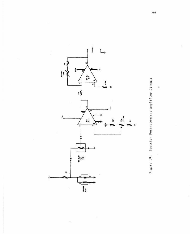
To assess performance, position variables (as functions of time) were
measured independently using precision, servo mount potentiometers as linear
position transducers. ..
A single turn, precision potentiometer equipped with a
small spur gear was interfaced to a rack assembly which was fastened to the
movable portion of the pitch yoke. When the viper of the transducer was
interfaced with the DC amplifier shown in Figure 19, the resulting voltage
output level was linearly related to yoke position, and, hence, to the instan-
taneous angle-of-attack. The principal source of error in establishing this
relationship, gear-rack backlash, was estimated to be less than 0.05% for
unidireetional motions.
A similar arrangement vas configured for the translational drive stage
using a ten turn, precision potentiometer and an appropriately sized gear.
In this case, translational position was measured directly.
Analog position signals were digitized through the LPS-11 analog/digital
converter interface available with the PDP 11/45 data acquisition system and
stored on disk. Performance tests were conducted under "no flow" conditions
for pitch-only, translation-only and combined pitch/translational conditions.
Several actual time histories obtained for a range of pitch rates are
displayed in Figures 20 and 21. The data provided in these illustrations
represent a request for a constant rate of change in angle-of-attack (a) from

214
zero degrees to a prescribed level (a ma ) with delay and a subsequent 'RETURN
HOME' command at a later time. At low to moderate rates (100/sec <
500"0 /sec), the actual motion time history was quite consistent with the
programmed "request." The linear region is observed to extend to Ca with
sharp acceleration and deceleration characteristics near motion initiation
and termination, respectively. Extensive tests did verify, however, that it
was necessary to "tune" the entire system in order to optimize performance
and to obtain faithfully reproducible response from test to test, even for
the lower oscillation rates. The tuning process included not only adjusting
the servo system gain and electronic response for critically damped behavrior
as might be expected, but also the painstaking alignment of all moving
mechanical components to eliminate friction and binding to the maximum extc-n.
possible.
At higher frequencies, inherent performance limitations were responsible
for varying degrees of degraded motion response. The curve depicted in
Figure 21 is representative of this behavior for constant rate motion. The
curve has been divided into three regions to facilitate a discussion of the
dynamic characteristics.
The initial acceleration is not "instantaneous" in this time scale of
motion as is shown in the segment labeled region I. Limitations on acce.ira-
tion capability resulted from the torque limitations of the motor gearbox
system as well as the maximum pulse frequency output of the microcomputer.
As previously mentioned, with the yoked drive arrangement employed, more
pulses were required to move a finite displacement (Act or Ax) when the yoke
was near either end of its range of motion, i.e., during the initial and
final portions of the motion cycle. There is even a slight delay in ti-

22
onset of motion (no greater than 0.02 sec) which can be a ttr i buted to the
time response of the electronics and software - a fixed delay time .
The linearity of the constant rate region (II) i s observed to be a strong
function of the rate itself. From rates in excess o f approximately 500
degrees per second to those in excess of 1,100 degrees per second (the maximum
attempted), the linear portion of the curve was f ound to extend from a start ing
angle (a1) which was typically fixed at about four degrees (well under the
static stall value) to a maximum level (a2) which was a fractional portion of
the maximum actual value. Typically -
..
In this example, a 2 a 55 degrees for a pr ogr ammed maximum o f 60 degr ees and an
actual value , a3
= 62 degrees . It should be noted that the maximum obtainable
limit with the internal cam (flywheel) adjus t ed for maximum radius (r2, from
equation (1)) wa~ a = 6·8. J degrees. The nonlinearity of this region was max
typically no worse than 4- 5% f or the hi ghes t rat es a t ta i nabl e based on a best
linear fit curve.
The deceleration phase (region III) is characterized by an overshoot of
the desired termination a~gle (a ) followed by a damped osci llat ion to max
equilibrium. The extent of t he overshoot was fixed at about 3-4% of a , max . but the damping was found to be dependent on the actual r a t e , a. This
behavior is attributable to the previously described l i mitations on the
maximum frequency and torque capabilities of the sys tem to respond to an
"instantaneous" deceleration request.
An item of concern, especially at high programmed rates, is th~ abiltty
of the drive unit to provtde the actual requested rate during the linear seg-
ment of motion. The example provided in Figure 21 does appear to indicate a
difference between the 'real' and the 'ideal' rates. These results are
summarized for a range of rates in Figure 22. The data represent actual
rates measured over the linear region only using a 'best fit' curve. The
departure from ideal motion is observed to increase with increasing rate in
a slight!~· nonlinear fashion.
23
Similar results are provided for the pitch oscillation mechanism for the
case of acceleration at constant rate, that is, a = constant, as shown in
Figure 23. After the maximum angle has been reached, the level is held until
the 'RETURN HOME' command. has been provided. These data reveal less over
shoot and oscillation during the deceleration part of the motion when colnpared
to the constant rate motion. A comparison of actual versus programmed
acceleration is provided in Figure 24 showing a closer adherence to desired
performance than that depicted for constant rate motion.
Comparable results are ptovided for the translational drive stage in
Figures 25-27. Performance indicators for thi~ unit are similar to those
discussed previously for the pitch mechanism. It must again be noted that
the inertial limitations of this unit are much more severe than for the
smaller pitch apparatus, and this is reflected in the 'frequency' range
depicted in the figures. · The maximum translational rate attempted under
"no-flow" test conditions for this report was x = .:;o inches per second. The
significance of this performance parameter is appa~ent when it is compared
with the minimum streaming velocities to which the model might be subj ected .
The USAFA subsonic wind tunnel provided test section flo~ velocities down to
32 feet per second {with special modifications) which results i n a typical
speed perturbation of approximately 16%.
An issue of equal concern to those mentioned previously is the : int egrity '
of resultant motion, or, ·cycle-to-cycle repeatability. Although the act ual

. ~~.
24
performance of both stages was observed to depart from the programmed
parameters, the measured repeatability of the resultant motion was found to
be excellent. Even after prolonged periods ( > 500 cycles), no deviat i on in
repeated oscillograph traces of the motion time histories was detectable.
The overall repeatability of the patterns, irrespective of the type of motion
or drive uni t , is estimated to be within one-half of one per cent.
Several tests involving simultaneous motion of both stages were conducted
to assess possible degradation of motion due to inertf al interference effects .
Figure 28 illustrates one example of combined motion. In this case, an axial ..
deceleration is coupled with a delayed pitch moti on at constant rate. In
these tests, no apparent alteration of the indepencent motions was observed
due to the coupling.
Finally, it is useful to discuss the performance 'map' under streaming
conditions. A typical result is provi ded for the pitch drive unit (Figure 29)
which shows the envelope of constant "quality" motion as a function of the
test section flow velocity. A diagram of this type could also be generated
for t he translational axis. Of course , this family of curves would be altered
if a different model (inertial characteristics) were employed. I f other than
constant rate motion were considered, the ordi nate would have to be redefined
to reflect the relevant performance variables.
25
VI. Summary
An oscillator mechaninm which provides complex motions in two degrees-of
freedom has been described. The device, originally designed for the investi
gation of motion variations in dynamic stall, employs a unique microcomputer
controlled, servo system concept to generate a virtually infinite combination
of motion alternatives in simultaneous rotation and translation. A prelim
inary performance evaluation indicates that the apparatus is capable of
generating relatively large amplitude dynamic motions at high frequencies.
Performance limitations have also been documented.

References
1. McAlister, K. w., Carr, L. w., and McCroskey, w. J., " Dynamic Stall Exper i -
ments on the NACA 0012 Airfoil , " NASA Technical Paper 1100, January 1978,
162 pages.
2. Parker, A. G., "Force and Pressure Measurements on an Airfoil Oscillating
Through Stall," Journal of Aircraft, Vol. 13, No. 10, October 1976, pp.
823-827.
3. St. Hilaire, A. o., Carta, F. 0., Fink, M. R., and Jepson, w. D., "The
Influence of Sweep on the Aerodynamic Loading of an Oscillating NACA. 0012 .. Airfoil," NASA Contractor Report 3092, May 1979.
4. Francis, M.s., Keesee, J. E., Lang, J . D., Sparks, G. w. , and Sisson,
G. E., "Ae rodynami c Characteristics of an Unsteady Separated Flow,"
AIAA Journal, Vol. 17, No. 12, December 1979, pp . 1332-1339.
5. Viets, H., Piatt, M., and Ball, M., "Boundary Layer Cont rol by Unsteady
Vortex Generation," Proceedings- Sympos ium on Aerodynamic s of Transporta-
tion (ASME), June 1979.
6. Kechbauch, Thomas J., "The Servodrive- it r eally does make a difference,"
Tooling ~ Productio~ Magazine, December 1976.

27
Acknowledgements
The authors wish to gratefully acknowledge the painstaking efforts of
Mr. Carl Geddes, whose talent and expertise are responsible for the fabrica-
tion and successful operation of the two degree-of-freedom oscillation
mechanism. Dr. (then, Captain) Stephen Batill and Mr. (then, Lieutenant)
Paul Duesing are to be especially comended for their contributions to the
complex mechanical design of the apparatus. Captain James Lind assisted
greatly in the development of the computer interface and control software.
The oscillator mechanism was constructed as part of a sponsored research
effort supported by the Frank J. Seiler Research Laboratory. Additional
support was also provided by the Flight Dynamics Laboratory of the Air Force
Wright Aeronautical Laboratories.

28
-J
* LJJ
- o
0 I 0'
I fI
= °
-'I o-I -
- -

Pu--
29
1'
I.
*~r.

C33

31
COC
0 0.-
522
L I I I
0 op
*~~~ 04OC 30 W
uh 000 0 z
(spumeg)~~~ Ltt W4!~
2 Ir

,2!KJ
AIRFOIL
TANG K
Side View
Bottom View
Figure 5. Model Mounting Detail

33
0~0
co~zU
16C

IjI
Lii
I cc
3 5

36
Top View
R~UB ER SEAL"
Sectionst End View
Figure q*Neoprene3 Slot Seal
37
w u4
> --
enLi
LU c)
> ciLU 0
LUu
LUcc L.
Li i V
(0 cc.
LU C
00 > ui 2* C.tU 0 >
IAJ C)
CLC
CL)
0Z
CL
41~
LU
cI-UWJ 6W
Lm)
0>C
Cdd
o or
39
CL.l
ci0CJ2
w CL-- CL D
L~i Q. c
c.n
(LAJ
CC.)
~ -..-

40
- -c
0 7I
z-
Z-
0 PFULfl
el

41
W! >
0uj cn
C* %n
.r
cc U
LA, LU
(UA.U uj
< W
> =-
Cc
C~1-.
~. LU
L&Jn
C -3

42
z z(
2~1

43
22
00 E
0 0. cu
32i
---- A
I0 -C
L.: -- -- - -- - - --
w -I 0:.
C3I
el Mai

VE
CT
OR
5
v 5
··
,----<
701(
~.20p
t ~~.
.J
L O
tpt
-r-
;;
I ... J"l
I I"
AT
HO
ME
E
22
oe
c 4
70
~D
n PO
P 11
145
~
14
13
12
11
1
0
9 8
14
13
12
11
10
9
SW1
OM
74
121
OM
74
121
A
• 1
2 3
4 5
6 1
• 1
2 3
4 5
-n A
tiA
2IF
I I
0 I
J -n
Ati
A2I
B
a PU
LSE
OU
T
A
6
~0
•ch
d
l_ .0
1p:
SW
1 PO
P 1.1
-03
B
v
!JC
OM
PUT
EII
RE
T H
OM
E
8 12
n
nlu
l ~ O
tpt
OU
TPU
T (B
ERG
CO
NN
EC
TO
R)
GN
D
H
2
1 u
u
'--
· -
1.~2
I 14
13
12
11
10
9
8 A
MP
H
~1
5-
PIN
O
M 7
411
TB2
H~
AT
HO
ME
E
21
•
I 2
3 4
5 6
7 5
J J,
IND
EX
-S
YN
ST
-IO
J R
ET
llO
ME
A
14
3
DIR
EC
TIO
N
B
16
SE
RV
O-
7 P
UL
SE
S
[I
18
TR
AN
SlA
TOR
8 9
GN
D
H
2
....._
--.,..
r •t
fttf
f' i
n p1
uns
-tr
&nd
•t•o
nal d
riv
t co
nne
tfio
n. o
thtn
-pi
tch
F i.g
u rc
l 7
. H
i.c
roco
mp
utc
r ln
tcr
f·acc
ci
rcu
it
-S
ing
le Ch
r~nne
l S
chem
ati
c
8 1 J
~ S\
'11
c
~
~

INIT
IAT
E M
OTI
ON
SE
LEC
TIO
N
PR
OG
RA
M (fi
ll A
RR
AY
S)
INP
UT
DE
SIR
ED
TIM
E D
ELA
YS
FO
R
STA
RTI
NG
PIT
CH
ITR
AN
SLA
TIO
NA
L M
OTI
ON
}
I D
RIV
EN
I
HA
RM
ON
IC M
OTI
ON
I
CO
NS
TAN
T R
ATE
I
CO
NS
TAN
T A
CC
ELE
RA
TIO
N
RE
QU
IRE
D
IN:~;s
I INON
EI I FRE
QU
EN
CY
I PITC
H R
ATE
I PITC
H A
CC
ELE
RA
TIO
N
MA
XIM
UM
AN
GLE
IN
ITIA
L PI
TCH
RA
TE
PIT
CH
O
F A
TTA
CH
M
AX
IMU
M A
NG
LE O
F A
TTA
CH
RE
QU
IRE
D
} IN
PU
TS
FOR
TR
AN
SLA
TIO
N
NO
T D
RIV
EN
(NO
NE
I
HA
RM
ON
IC M
OTI
ON
FRE
QU
EN
CY
L------L
----------
'----
----
----
----
---
• CO
NS
TAN
T R
ATE
TRA
NS
LATI
ON
RA
TE
MA
XIM
UM
EX
TEN
T O
F T
RA
VE
L
+
CO
NS
TAN
T A
CC
ELE
RA
TIO
N
TRA
NS
LATI
ON
AL
AC
CE
LER
· A
T IO
N
INIT
IAL
RA
TE
MA
XIM
UM
EX
TEN
T O
F T
RA
VE
L
~-
WAIT FO
R 'R
UN
' CO
MM
ANO
FR
OM
~COMPUTER (I
NIT
IAT
E P
ULS
E O
UTP
UTI
fig
ure
18
. S
.:lc
ct.
ion
o
f H
ot
ion
Ch
ara
cL
eri
">ti
cs
J l:
o..n
LM39
9 6.
9.
•15w
T
?"
I.S
k
SE
RV
O
POT
ISK
I
Fig
ure
1
9.
~
+1
5¥
JJI(
201C
IZ
£R
OI
11
(
·15v
~
Po
siti
on
P
ote
nti
om
ete
r A
mp
lifi
er
Cir
cu
it IS
PA
NI
10
01
(
10
OU
TP
UT
r
.,. a-

47
C
"'0
00 ~ 4
1 '.3CCC
C 3)
- C
C
U.43I -'*1-C
C)
4
r-&o
')
a
OJ
~ ..
m
I L_-
------
------
------
-~,L-'
----1'
, a1
I
/
o,
,
I , , , ,
, , ,
I , , I I I
.02
, , , I , I I , I ,
.04
PRO
GRA
MM
ED M
OTIO
N (I
DEA
L R
ESPO
NSE
I
AC
TUA
L M
OTI
ON
.06
08
.10
TIM
E h
eel
Fig
ure
21
. P
itch
O
scil
lato
r P
erf
orm
an
ce,
Co
nst
an
t Rate
M
otio
n,
Hig
h F
req
uen
cy
(Typic~
!)
-C
CX>
-w _
49
C '4'-4C
0 C) 44-4
4-4 *
a - CC
I - C,
~
0C-,
C
5-4Cd
N UN
UC-"
4 C)
U..40
Co.
~ - -~ - - -~ ~ ~ ..- -~ ~-=-..-----
I
50
L
C.)
-4
*1IC
0
2
0
U
0 C 0 0
I I I 10
'-'I
0)
C 2
I

1
51
C
I-
we -j
-~ J-JCQ
C
C-
0~'tG -~ C-,
I bi j~1

52
C
C
.1? CC)
C
U
4-I -
C-
.I~. ~'
I., 0
U
H
o *1 C
C
2.JO~ to

53
%d0
cc
cz C:
'0
4. -
% 4, . ,
' 'C
S -'
¢I

54
i'o *~
- .-. '1'4- ~
~
0Ca-->4-
'C 4-
I~.I ~z -~
-'4-I --I -
-'C~\\\\ ~
I-.C-I
3
-J
I-..
C
4.
I~.

4, 55
U
C..,
J-J
0
I,-'4
C
j
C
F0
'0'V
C-)
L
o1~
4
r
56
U,
0
~1 I.
4, 4~ -~
0
on L
14
C. I.F C'
a IC'
- C' .4CU.4 4-,a: 14
C..
U,
.4. x
U
C..
'aI- C
C'(-.4
w1..
4, 0on
4. -. 4-.. - '.4 -, -


![SEILER John SL414 - E. C. Saylor · John "Hans" SEILER and Elizabeth BLOUGH 1. John "Hans"1 SEILER [SL414+], born i, 26 Aug 1768 in Pennsylvania; died i 4 Mar 1855, son of John SEILER](https://static.fdocuments.net/doc/165x107/5b5cba237f8b9a3a718cdb1f/seiler-john-sl414-e-c-john-hans-seiler-and-elizabeth-blough-1-john-hans1.jpg)