Fractional-Order-Based ACC/CACC Algorithm for Improving ...
17
HAL Id: hal-01896558 https://hal.inria.fr/hal-01896558 Submitted on 16 Oct 2018 HAL is a multi-disciplinary open access archive for the deposit and dissemination of sci- entific research documents, whether they are pub- lished or not. The documents may come from teaching and research institutions in France or abroad, or from public or private research centers. L’archive ouverte pluridisciplinaire HAL, est destinée au dépôt et à la diffusion de documents scientifiques de niveau recherche, publiés ou non, émanant des établissements d’enseignement et de recherche français ou étrangers, des laboratoires publics ou privés. Fractional-Order-Based ACC/CACC Algorithm for Improving String Stability Carlos Flores, Vicente Milanés To cite this version: Carlos Flores, Vicente Milanés. Fractional-Order-Based ACC/CACC Algorithm for Improving String Stability. Transportation research. Part C, Emerging technologies, Elsevier, In press. hal-01896558
Transcript of Fractional-Order-Based ACC/CACC Algorithm for Improving ...

HAL Id: hal-01896558https://hal.inria.fr/hal-01896558
Submitted on 16 Oct 2018
HAL is a multi-disciplinary open accessarchive for the deposit and dissemination of sci-entific research documents, whether they are pub-lished or not. The documents may come fromteaching and research institutions in France orabroad, or from public or private research centers.
L’archive ouverte pluridisciplinaire HAL, estdestinée au dépôt et à la diffusion de documentsscientifiques de niveau recherche, publiés ou non,émanant des établissements d’enseignement et derecherche français ou étrangers, des laboratoirespublics ou privés.
Fractional-Order-Based ACC/CACC Algorithm forImproving String Stability
Carlos Flores, Vicente Milanés
To cite this version:Carlos Flores, Vicente Milanés. Fractional-Order-Based ACC/CACC Algorithm for Improving StringStability. Transportation research. Part C, Emerging technologies, Elsevier, In press. �hal-01896558�

Fractional-Order-Based ACC/CACC Algorithm for Improving StringStability
Carlos Flores and Vicente Milanes.
Carlos Flores is with the Robotics and Intelligent Transportation Systems (RITS) Team, INRIA Paris, 2 Rue Simone Iff,75012 France5
Vicente Milanes is with the Research Department, Renault SAS, 1 Avenue de Golf, 78280 Guyancourt, France
Abstract
Traffic flow optimization and driver comfort enhancement are the main contributions of an Adaptive CruiseControl (ACC) system. If communication links are added, more safety and shorter gaps can be reached per-forming a Cooperative-ACC (CACC). Although shortening the inter-vehicular distances directly improvestraffic flow, it can cause string unstable behavior. This paper presents fractional-order-based control algo-rithms to enhance the car-following and string stability performance for both ACC and CACC vehicle strings,including communication temporal delay effects. The proposed controller is compared with state-of-the-artimplementations, exhibiting better performance. Simulation and real experiments have been conducted forvalidating the approach.
Keywords: Adaptive Cruise Control, Cooperative Adaptive Cruise Control, String Stability,Fractional-Order Calculus, Cooperative Systems, Intelligent Transportation Systems
1. Introduction10
Car-following systems are of the most promising Advanced Driver Assistance System (ADAS) for im-proving both traffic safety and flow. It is based on a front range sensor for detecting the preceding vehicle,adapting the ego-vehicle speed accordingly–i.e. Adaptive Cruise Control (ACC). This technique permitsto efficiently track the preceding vehicle maintaining a desired distance. The evolution of such alreadycommercial technology is the Cooperative-ACC (CACC), which proposes to add vehicle-to-vehicle (V2V)15
communication links to maintain tigher string formations.Recent works have demonstrated CACC benefits with respect to ACC [19]. The main contributions
of CACC systems are an improvement in traffic throughput due to shorter inter-vehicle distances and theenhancement of drivers’ safety and comfort [38]. As main limitations, the V2V communications must beguaranteed for achieving these results. Moreover, the temporal delay that these links may present affects20
the dynamic performance of the car-following maneuver, threatening directly the string stability and leadingto undesirable behavior.
Platooning systems have been firstly tested on real roads by the Partners for Advanced TransportationTechnology (PATH) in 1997 [34], performing platoon formations with highly short inter-distances, whichrequired high interaction with the leader vehicle and dedicated lanes. More recently, the PATH has also25
contributed with several research works in CACC [25, 39, 37]. Other projects as Connect & Drive [6]have approached CACC considering possible interaction with other cars in highways. They have shownpositive results that demonstrate an increase in terms of safety and traffic throughput. In addition, thistechnique has gained more attention recently through research competitions as the first Grand CooperativeDriving Challenge (GCDC) 2011 [9] and the second GCDC in 2016 under the i-Game EU project1 umbrella.30
1http://www.gcdc.net/en/i-game
Preprint submitted to Transportation Research Part C: Emerging Technologies July 26, 2018

The platoon frequency response and the string stability notion are addressed by the work of [23]. Otherapproaches have applied different control structures and techniques to provide encouraging performances;such as Model Predictive Control (MPC) [14], sliding mode control [15] or H∞ controller-based approaches[31, 8]. Robust performances have been obtained when more complex topologies are used [48, 35]. Finally,one-vehicle look-ahead feedforward structures with Proportional-Derivative (PD) feedback controllers [20, 30]35
have been widely employed in the literature providing great results due to its damping properties, practicalimplementation and low computational cost.
Almost all state-of-the-art approaches that address this problem are based in integer order control (IOC),which encourages the usage of non-integer order techniques to reach even more exigent performances. Frac-tional order control has arisen as a frequently employed mathematical tool to fulfil more demanding design40
requirements, due to its capabilities to provide a more precise and adaptable frequency response [46]. Thistechnique has been already employed in car-following approaches, firstly for a hybrid ACC control design[10], a low level throttle and brake control for ACC [11] and finally a CACC controller robust against plantgain disturbances [7].
This work proposes to employ fractional control to design feedforward structures for both ACC and45
CACC, aiming to enhance the stability and achieve formations with shorter time gaps and improved systemperformance. It is proposed to profit from the more adaptable frequency response that fractional-ordercontrol (FOC) provides in comparison to classical controllers. The performance is studied through stringstability analysis of the designed controller and state-of-the-art solutions for ACC and CACC. The improve-ments in terms of string stability of the FOC approach with respect to state-of-the-art IOC solutions are50
demonstrated in simulations and real platforms tests.The rest of this paper is structured as follows: Section II introduces the concepts and definitions asso-
ciated to ACC/CACC systems. An introduction to fractional-order calculus and its applications in controlis stated in Section III. Section IV describes the model of the experimental platform that is going to beused for the controller synthesis. The proposed feedforward structure and the controller design procedure55
for ACC and CACC are presented in Section V and VI respectively. In Section VII, a comparative studyof the proposed algorithm for both ACC and CACC systems is described, including a comparison withstate-of-the-art developments. The conclusions derived from the obtained results and possible future workare stated in the Section VII.
2. Concept and definitions60
When it comes to analyze car-following string of vehicles, there are two main concepts to be considered:1) the adopted car-following policy; and 2) the string stability of the formed platoon. This section reviewsboth concepts.
Attending to the car-following policy, different strategies can be found in the literature:
1. Constant clearance was conceived as a strategy aimed mainly for platooning maneuvers [42], which65
consists on driving in highway with really close distance gaps. This approach requires dedicated lanesand low latency V2V communication links with the leader vehicle to handle very short spacing.
2. Constant Time Gap (CTG) constitutes one of the most employed and flexible spacing policies. Itsuggests to perform a vehicle tracking with non fixed distances [43]. It simulates the way how humansdrive since it proposes to set higher distances when the speed increases, using a time gap multiplied70
by the ego-speed added to a fixed standstill distance.
3. Constant safety factor is another frequently employed spacing policy [12]. This technique proposesto have a more reactive and conservative behavior in case a hard braking is executed by a forwardvehicle, adding a term that penalizes the difference between both vehicles’ speeds.
4. Variable Time Gap (VTG) is a spacing policy that has been addressed by some recent research75
works, suggesting to variate the time gap while driving, with different purposes and in function of theego-speed. For example, accomplishing improved traffic flow stability [49] or enhanced safety [47] andcomfort [18].
2

Another fundamental notion and important design requirement of car-following techniques is the stringstability, which states that every string formation must not propagate the disturbances upstream. This80
concept can be understood from the scope of Lyapunov stability, where it may be interpreted as the asymp-totic stability of a finite number of interconnected individual exponentially stable systems [41]. The mainobjective of the car-following-oriented approaches that address this phenomenon is to ensure the attenua-tion of any perturbation along the string, avoiding undesired behaviors. This concept is better described inequations:85
‖zi(t)‖∞ ≤ ‖zi−1(t)‖∞;∀ t ≥ 0; 2 ≤ i ≤ m; (1)
‖Γ(jω)‖∞ ≡∣∣∣∣∣∣∣∣ Zi(jω)
Zi−1(jω)
∣∣∣∣∣∣∣∣∞≤ 1; ∀ω > 0; (2)
where zi(t) is understood as a representative dynamic variable of the ith vehicle of an homogeneous stringof m members–i.e. spacing error, position, speed or acceleration–and Zi(jω) its frequency domain inter-pretation. Both Eq. 1 and 2 describe the fact that the ego-vehicle should not amplify the behavior of itspreceding car, so the string formation can be extended boundlessly maintaining the desired behavior. TheCTG spacing policy is employed in this work, given that it allows to determine the string stability limit of90
the system directly by surveying the minimal allowed time gap that guarantees a string stable gap-regulationcontrol.
3. Fractional-Order Calculus
When it comes to phenomena representation through mathematical modelling, the integer-order calculushas been always the main tool employed in science and engineering applications [1]. However, the necessity of95
more descriptive and precise solutions yielded that fractional-order control arised as a new tool, gaining moreand more attention due to its capability for modelling systems more accurately [2]. Some physical systemsare more exactly represented using fractional-order models [44]; for example those where the viscoelasticityis fundamental, the notion of fractal robustness [27] or the case of voltage-current relation of a semi-infinitelossy RC line [45]. Thus, the generalization of the differential and integral operator of real order results100
necessary to better describe these phenomena is:
aDαt =
dα
dtα → α ∈ R > 01→ R(α) = 0∫ ta(dτ)−α → α ∈ R < 0
(3)
where D is the operator that exist in the time range t ∈ (a, t) and α the operator order. A more descriptivenon-integer order differentiation or integration formula is required to further develop applications withfractional-order calculus. Several time-domain interpretations have been proposed to this operator, whereone of the most frequently used was proposed by Caputo [3]. It provides a solution where the initial conditions105
for the fractional differential equation take the same form as for integer-order ones and consequently, theytake a physical interpretation. The differentiation operator with respect to time t with a starting point oft = 0, proposed by Caputo is:
0Dαt =
1
Γ(m− α)
∫ t
0
f (m)(τ)
(t− τ)α−m+1(dτ), m− 1 < α < m, m ∈ N (4)
where the term Γ(n) is the Euler function. Fig. 1 shows different fractional-order operators applied over atriangular signal with a DC value. It can be appreciated how the signal manipulation changes as the order110
varies, from the unit gain (α = 0) to the first-order derivation (α = 1). This operator can be also translatedto the frequency domain as:
L{aDαt f(t)} = sαF (s) (5)
3

15 20 25 30 35 40
0
0.5
1
1.5
2
2.5
3
Time (sec)
Valu
e
Original Signal
alpha=0.25
alpha=0.75
alpha=0.5
alpha=1
Figure 1: Time plot of a different order derivation applied to a triangular signal
where f(t) and F (s) stands for the function in its time and frequency domain form respectively. As it can bededuced, it constitutes a powerful signal processing feature and consequently, it has been widely employedin the control field in state-of-the-art and industrial approaches with great results [5].115
3.1. Fractional Control
The integer-order calculus has been the most employed tool for systems control design in industrialenvironments; being the Proportional-Integral-Derivative (PID) the most employed controller [1]. AlthoughIOC has provided great results, the development of more complex control systems requires flexible andaccurate controller design methods to satisfy more challenging closed-loop performances. Different control120
techniques have been proposed that profit from the fractional-order calculus to satisfy more demandingtuning strategies. The first fractional control approach was proposed by [26] with the non-integer robustcommand (CRONE, from the french Commande Robuste d’ordre non entier) that aims to maintain thesystem open loop phase margin unvaried, achieving the so-called fractal robustness [27]. The fractional-order lead-lag compensator [21] and the Tilt-Integral-Derivative controller [17] are also other approaches of125
non-integer controllers that have provided encouraging performances.In this work, a specific fractional-order control technique is chosen to develop the gap regulation con-
troller, which is the real order generalization of the PID, the PIλDα controller [32]. This technique takesas a basis the mathematical form of the PID, stating that its integral and derivative operators (λ andα respectively) should not necessarily have order 1, but it will be possible to have both integration and130
differentiation of real order. The control law proposed by this approach is described as follows:
C(s) =E(s)
U(s)= Kp+Kd · sα +Ki · s−λ; (α, λ) > 0 (6)
where two design parameters are added (α, λ), allowing not only to modify the contribution of each integra-tion and differentiation operator respectively, but also to modify their behavior. E(s) and U(s) represent thespacing error and feedback controller output respectively. This permits to have five design parameters anda more flexible frequency response and thus, permitting to move in the plane presented in Fig. 2a instead135
of only being able to yield control actions within the 4 black points–i.e. P, PD, PI and PID controllers.Another approaches have proposed to employ controllers of the form PIλ [22] or PDα [16, 13] to achievethe desired behavior where it is not required to have all the operators of the real-order PID.
In the frequency domain, by introducing the non-integer orders of the differentiator or integrator, thedesign process can not only modify the pole/zero placement, but also the whole magnitude and phase140
contribution of the controller. For example, a differential operator with order α provides a phase increaseslope of +απ2 rad/dec and a magnitude contribution of +α20 dB/dec. The resulting controller yields abehavior as presented in Fig. 2b where the contribution of the controller zeros and poles is modified by theoperators’ real orders.
4

(a) Differentiation behavioral plane
0
20
40
60
80
100
Magnitude (
dB
)
10�4
10�3
10�2
10�1
100
101
102
103
104
90
45
0
45
90
Phase (
deg)
Bode Diagram
Frequency (rad/s)
Fractional PID
Integer PID
(b) Comparisson between a PID (green line) with the gains(Kp = Ki = Kd = 1), and a Fractional PID with the samegains but the orders λ = 0.4 and α = 0.8
Figure 2: Fractional-order control frequency effect illustration
4. Vehicle Model145
This section introduces the experimental platform that will be later used in the real tests as well as themodelling of its longitudinal response.
4.1. Cybercars
These prototypes have been conceived as an efficient mobility service for urban environments, with thepurpose of inserting the intelligent transportation systems into the cities and society [28]. They are equipped150
with on-board sensors and an embedded computer to process the gathered data, in order to generate thelateral and longitudinal commands. To provide car-following capabilities, Cybercars are equipped withfront LiDAR (Light Detection and Ranging) sensors to measure the distance between the ego-vehicle andits preceding one. They are also capable to transmit their dynamic variables through communication linksto the other string members for further processing. The experimental platform employed for this work is155
the 4-wheeled electrical prototypes Cycabs (see Fig. 3a). They were conceived to operate in urban scenarioswith frequent interaction with vulnerable road users and for this reason their maximum speed is set to 5m/s.
4.2. Model Identification
For the longitudinal model identification, a reference speed profile is given to the low level control of the160
vehicle. Fig. 3b shows the experimental identification, where the black line describes the given referencespeed, red line depicts the measured speed and blue one shows the fitted model response.
(a) Cycabs string formation
20 25 30 35 40 45 50
Time (sec)
0
1
2
3
4
Vel
ociti
es (
m/s
)
Measured speedReference speedFitted model
(b) Speed reference, vehicle real speed and model
Figure 3: Experimental platforms illustration and dynamic behavior modelling
5

For the model identification, the MATLAB toolbox ident is used. The experimental identification processdemonstrates that the longitudinal vehicle dynamics and actuator lags can be modelled using a second-ordertransfer function as:
Gp(s) =ωn
2
ωn2 + 2ξwns+ s2(7)
where ξ = 0.3391 is the damping factor and wn = 2.5754 rad/sec is the plant natural frequency.
5. ACC Control Design
This section presents the control structure for the ACC algorithm and the fractional-order controller165
design.
5.1. Control Structure
For the ACC strategy, the controller output acts as a real-time correction over the ego-speed in the innerfeedback loop. This generates the reference speed that the low-level control of the vehicle must track.
The outer feedback loop is composed by theH(s) block, which describes the spacing policy (H(s) = hs+1,170
being h the time gap). It provides the desired distance gap, that will be compared with the current measureddistance to output the spacing error, upon which the control law C(s) is further applied. The block Gp(s)represents the vehicle model identified in Sec. 4.
For the FOPD tuning process in the ACC case (see Fig. 4), the transfer function Gpfb(s) summarizesthe controlled model of the form:175
Xi(s)
Ui(s)= Gpfb(s) =
Gp(s)
s(1−Gp(s))=
ωn2
s2 (s+ 2ξωn); (8)
The block diagram in Fig. 4a shows the ACC control structure based on speed reference command. Theinner control loop can be replaced by Gpfb(s) leading to the control structure in Fig. 4b.
(a) ACC Control structure with Gp(s) (b) ACC control structure with Gpfb(s)
Figure 4: ACC Control Structure
5.2. FOPD Design Algorithm
As it was previously stated, several state-of-the-art approaches have used lead controllers as PD insteadof PID because the system damping and enhanced stability are fundamental in car-following approaches180
[20, 29]. It is proposed then to employ a non-integer-order PD controller for the gap regulation task in ACC,in other words, a Fractional-Order PD (FOPD) controller which control law is:
Ui(jω)
Ei(jω)= C(jω) = Kp ·
(1 + j
ωα
ωc
)(9)
It has been demonstrated that for some applications, the optimal FOPD outperforms the optimal integer-order PD (IOPD) [4]. This type of controller posses a non-integer derivative, which allows to have one moreparameter than IOPD to tune, and satisfy a more demanding frequency response.185
6

The FOPD controller design procedure is aimed not only to ensure the loop stability for the gap-regulation task with a desired system bandwidth and phase margin, but also to increase the string stabilitywhen applied on a homogeneous string of vehicles. To achieve so, the procedure demands to obtain theoptimal configuration of the controller gain Kp, central frequency ωc and the differentiation order α to fulfilthe three requirements: maintain the vehicle response bandwidth when closing the loop, a desired phase190
margin and guarantee the string stability for the lowest time gap possible.The estimation of the system bandwidth and phase margin when applying the CTG policy is studied
over the loop expression LACC(s) = Gpfb(s)C(s)H(s). Its gaincross frequency ωgc should be similar to thevehicle’s one (it is proposed ωgc = 3.5 ± 0.1 rad/sec), lower values of ωgc limit the system reaction speedand higher values may yield saturation and non-linearities consequently. A phase margin of φ = (60± 1)◦ is195
targeted so the system is robust and stable, but not overdamped so it loses output-to-reference convergencespeed. The string stability requirement is analysed over the closed loop expression Eq. 2, which for theACC structure in Fig. 4 results:
||ΓACC(s)||∞ =
∣∣∣∣∣∣∣∣ Xi(s)
Xi−1(s)
∣∣∣∣∣∣∣∣∞
=
∣∣∣∣∣∣∣∣ C(s)Gpfb(s)
1 + C(s)Gpfb(s)H(s)
∣∣∣∣∣∣∣∣∞≤ 1; i ≥ 2 (10)
To retrieve the controller parameters, an optimization algorithm is executed for different values of husing the Matlab command fsolve, which allows to solve multi-objective non-linear optimization problem.200
The function to minimize results from the design requirements and interpreted as follows:
F (h) = W1 · |ωgc − 3.50|+W2 · |φ−π
3|+W3 · (||ΓACC(s)||∞ − 1); (11)
where F (h) is the function to be minimized for a given time gap h. The general guideline to set the weightsW1,W2 and W3 is to define a considerably higher cost to the string stability condition, given that it isstrictly required that ||ΓACC(s)||∞ ≤ 1.
The algorithm is executed lowering the time gap until a Pareto-front is reached and one or more design205
requirements are no longer fulfilled due to the more demanding performance necessary to hold shorter timegaps. If a lower time gap is desired with string stable performance, one of the other design requirementsmust be relaxed. For the purpose of this work, the controller parameters that permits the lowest h satisfyingthe design requirements stated above is kept. The expression:
C(jω) = 2.079 ·(
1 + jω1.075
2.640
)(12)
has been obtained as the optimal controller for the proposed requirements and the vehicle dynamics described210
by Eq. 7. With a time gap of h = 0.536s, it ensures a control structure with ||ΓACC(s)||∞ = 1 and a phasemargin of φ = 59.148◦ at the gaincross frequency ωgc = 3.556 rad/sec.
6. CACC Control Design
This section introduces the control structure modifications to benefit from V2V information coming fromthe preceding vehicle. Then, the fractional-order control algorithm to deal with CACC system is presented.215
6.1. Control Structure
The experimental platforms are commanded through a reference velocity, for this reason it is sent throughthe V2V communication link to the next vehicle in the string for its further usage as feedforward term. Thisapproach is based on the inverse-model feedforward control under the assumption of homogeneous strings,permitting faster responses towards a speed change of the preceding vehicle without requiring the feedback220
loop to correct it. The proposed feedforward/feedback control structure has been also employed on severalprevious approaches, where good results have been obtained when applied in CACC [20, 24, 25]. Fig. 5depicts that the plant input results from the addition of the feedforward term and the feedback FOPDcontroller output.
7
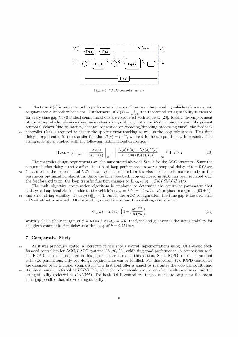
Figure 5: CACC control structure
The term F (s) is implemented to perform as a low-pass filter over the preceding vehicle reference speed225
to guarantee a smoother behavior. Furthermore, if F (s) = 1H(s) , the theoretical string stability is ensured
for every time gap h > 0 if ideal communications are considered with no delay [23]. Ideally, the employmentof preceding vehicle reference speed guarantees string stability, but since V2V communication links presenttemporal delays (due to latency, channel congestion or encoding/decoding processing time), the feedbackcontroller C(s) is required to ensure the spacing error tracking as well as the loop robustness. This time230
delay is represented in the transfer function D(s) = e−θs, where θ is the temporal delay in seconds. Thestring stability is studied with the following mathematical expression:
||ΓCACC(s)||∞ =
∣∣∣∣∣∣∣∣ Xi(s)
Xi−1(s)
∣∣∣∣∣∣∣∣∞
=
∣∣∣∣∣∣∣∣D(s)F (s) +Gp(s)C(s)
s+Gp(s)C(s)H(s)
∣∣∣∣∣∣∣∣∞≤ 1; i ≥ 2 (13)
The controller design requirements are the same stated above in Sec. 5 for the ACC structure. Since thecommunication delay directly affects the closed loop performance, a worst temporal delay of θ = 0.08 sec(measured in the experimental V2V network) is considered for the closed loop performance study in the235
parameter optimization algorithm. Since the inner feedback loop employed in ACC has been replaced withthe feedforward term, the loop transfer function changes to LCACC(s) = Gp(s)Gc(s)H(s)/s.
The multi-objective optimization algorithm is employed to determine the controller parameters thatsatisfy: a loop bandwidth similar to the vehicle’s (ωgc = 3.50 ± 0.1 rad/sec), a phase margin of (60 ± 1)◦
and strict string stability ||ΓCACC(s)||∞ ≤ 1. As for the ACC configuration, the time gap is lowered until240
a Pareto-front is reached. After executing several iterations, the resulting controller is:
C(jω) = 2.483 ·(
1 + jω1.188
3.625
)(14)
which yields a phase margin of φ = 60.031◦ at ωgc = 3.519 rad/sec and guarantees the string stability forthe given communication delay at a time gap of h = 0.254 sec.
7. Comparative Study
As it was previously stated, a literature review shows several implementations using IOPD-based feed-245
forward controllers for ACC/CACC systems [36, 20, 23], exhibiting good performance. A comparison withthe FOPD controller proposed in this paper is carried out in this section. Since IOPD controllers accountwith two parameters, only two design requirements can be fulfilled. For this reason, two IOPD controllersare designed to do a proper comparison. The first controller is aimed to guarantee the loop bandwidth andits phase margin (referred as IOPDPM ), while the other should ensure loop bandwidth and maximize the250
string stability (referred as IOPDSS). For both IOPD controllers, the solutions are sought for the lowesttime gap possible that allows string stability.
8

7.1. ACC and CACC Controllers
In Tab. 1 the FOPD and the two IOPD controllers are shown for the ACC control structure, as well asthe loop bandwidth, phase margin and minimum time gap of the system.255
Table 1: Controller parameters obtained for ACC, minimum time gap allowed and stability metrics
Controller Kp ωc α h[sec] φ[◦] ωgc[rad/sec] ||Γ(s)||∞
FOPDACC 2.079 2.640 1.075 0.536 59.148 3.556 1.000
IOPDPMACC 1.613 2.015 1.000 0.572 60.078 3.505 1.000
IOPDSSACC 1.919 2.399 1.000 0.538 54.153 3.504 1.000
All controllers produce the desired loop bandwidth, but it is observed that when designing an IOPD forthe phase margin requirement, the time gap cannot be lowered as much as if the design requirement wasmaximizing string stability. On the other hand, the FOPDACC controller is capable not only to ensurethe string stability for the same time gap than IOPDSS
ACC does, but also to provide the desired phasemargin. This demonstrates the compromise that exists when enhancing both the system performance and260
loop stability, which can be further improved profiting from the more flexible configuration of the fractional-order controller.
Such behavior is depicted as well in Fig. 6. In the left figure the frequency response of LACC(s) is showedwhen using the three controllers for their respective minimum time gap. The magnitude of their closed loopresponses is illustrated in the right figure setting a h = 0.536 sec. A clear difference is observed in the265
performance provided by the IOPDPMACC which results string unstable as the time gap set is lower than its
limit. For the other controllers, the results showed in the table are visible in Fig. 6b since their closed loopperformance results equal (a ||Γ(s)||∞=1) for the same time gap, but the phase margin is reduced in thecase of the IOPDSS
ACC (see Fig. 6a) with respect to what is provided by the FOPDACC controller.
-6
-4
-2
0
2
4
Ma
gn
itu
de
(d
B)
2.5 3 3.5 4 4.5 5 5.5 6
-140
-130
-120
-110
-100
Ph
ase
(d
eg
)
Bode Diagram
Gm = -Inf dB (at 0 rad/s) , Pm = 59.2 deg (at 3.56 rad/s)
Frequency (rad/s)
(a) Magnitude and phase of the loop response LACC(s)
0.2 0.4 0.6 0.8 1 1.2 1.4 1.6 1.8
-0.15
-0.1
-0.05
0
0.05
0.1
0.15
Magnitude (
dB
)
Bode Diagram
Frequency (rad/s)
(b) Magnitude of the closed loop response if a time gap ofh = 0.536 sec is set
Figure 6: Frequency analysis of the control structure having as feedback controller: FOPDACC (green line), IOPDSSACC (red
line) and IOPDPMACC (blue line)
For the CACC scenario, the performance evaluation is also carried out with two IOPD controllers: the270
first one optimizes the string stability and the second one the loop phase margin. In Tab. 2 the resultingcontrollers are presented, with the stability performance that they provide when a V2V temporal delay ofθ = 0.08 sec is considered.
It can be observed that if the FOPDCACC attains the three objectives for a minimum time gap ofh = 0.254 sec. On the other hand, when employing an IOPD controller for the same time gap, one must275
decide between either improving the system stability or increasing the closed loop performance with string
9

Table 2: Controller parameters obtained for CACC, minimum time gap allowed and stability metrics
Controller Kp ωc α h[sec] φ[◦] ωgc[rad/sec] ||Γ(s)||∞
FOPDCACC 2.483 3.625 1.188 0.254 60.031 3.556 1.000
IOPDPMCACC 1.613 2.395 1.000 0.308 60.103 3.507 1.000
IOPDSSCACC 2.367 3.734 1.000 0.260 42.851 3.501 1.000
stable behavior at a lower time gap. This is noticed in the properties of IOPDSSCACC controller, where even
if it ensures string stability for almost the same time gap than the FOPDCACC , the resulting phase marginis compromised. If the desired phase margin must be guaranteed with an IOPD controller, the time gapexigence must be relaxed to provide a string stable behavior. This is illustrated in Fig. 7, where the left280
figure depicts the bode response of LCACC(s) for the three mentioned controllers. In the right plot, theclosed loop magnitude response is studied using each of the three controllers with a time gap of h = 0.254 sec.In such figure, the IOPDPM
CACC controller presents string unstable behavior. For the other two controllersthe performances result almost similar, a difference is observed around ω = 0.5 rad/sec where the closedloop magnitude yielded by the IOPDSS
CACC results slightly higher than unity.285
-20
-10
0
10
Ma
gn
itu
de
(d
B)
100
101
-180
-135
-90
-45
Ph
ase
(d
eg
)
Bode Diagram
Gm = Inf dB (at Inf rad/s) , Pm = 59 deg (at 3.49 rad/s)
Frequency (rad/s)
(a) Magnitude and phase of the loop response LCACC(s)
10-1 100
-0.7
-0.6
-0.5
-0.4
-0.3
-0.2
-0.1
0
0.1
0.2
0.3
Ma
gn
itu
de
(d
B)
Bode Diagram
Frequency (rad/s)
(b) Magnitude of the closed loop response if a time gap ofh = 0.254 sec is set
Figure 7: Frequency analysis of the control structure having as feedback controller: FOPDCACC (green line), IOPDSSCACC
(red line) and IOPDPMCACC (blue line)
Since the V2V temporal delay affects directly the string stability, the minimum time gap that can be setis modified. Having the three controllers presented in Tab. 2 the communication delay in D(s) is varied asθ ∈ (0, 0.3)sec to study how the time gap must be modified to maintain the string stability. Fig. 8 shows thestudy for the three controllers designed previously. It is observed that lower time gaps require low latencycommunications as would be expected. This evidences the relevance of the feedforward term in this type290
of control structures, where ideal communications provide string stability for all time gaps higher than zero[23]. It is also worthy to mention that feedback loop robustness plays a key role for assuring string stability,overall when V2V temporal delays increase.
7.1.1. Simulations
A simulation of a string of 7 vehicles is carried out for both ACC and CACC algorithms (Fig. 9 and 10295
respectively). Three scenarios are evaluated for each technique, an IOPD controller tuned to fix the loopbandwidth and phase margin, another IOPD configured to provide the desired bandwidth and to maximizethe string stability and finally a FOPD that targets all the objectives stated before at the same time. For thesake of clarity, only the first and last vehicle performances are presented. The black solid line corresponds to
10

0.05 0.1 0.15 0.2 0.25 0.3 0.35 0.4 0.45 0.5 0.55 0.6Time gap (sec)
0
0.05
0.1
0.15
0.2
0.25
0.3V
2V m
axim
um d
elay
(se
c)
Figure 8: Maximum tolerable communication delay time for each time gap ensuring string stability for CACC strings for theFOPDCACC (green line), IOPDSS
CACC (red line) and IOPDPMCACC controllers
the leader vehicle speed profile. This profile is identical in the three simulation to allow a fair comparison.300
The red, blue and green solid lines plots the responses of the 7th IOPDPM , IOPDSS and FOPD controlledvehicles respectively.
All variables are updated at the sample frequency of the vehicle odometry f = 100Hz. For the simulationpurpose, the sensor noise has been omitted so the variables evolution is easier to visualize. For ACC andCACC scenarios, time gaps are set to 0.542 sec and 0.254 sec respectively added to a standstill distance of305
two meters. The same communication temporal delay of θ = 0.08 sec is assumed.
30 35 40 45 50 55
Time (sec)
5
10
15
Speed (
m/s
)
30 35 40 45 50 55
Time (sec)
-0.5
0
0.5
Err
ors
(m
)
30 35 40 45 50 55
Time (sec)
6
8
10
12
Spacin
g (
m)
Figure 9: Simulation tests in ACC 7-vehicle strings using three different controllers: IOPDSSACC (red line), IOPDPM
ACC (blueline) and FOPDACC (green line)
It is observed that with all the controllers, the speed changes are tracked and the spacing errors mitigatedalong time, showing stable performance. For CACC the inter-distances are smaller, and the speed changesare tracked in a faster way as a consequence of the lower time gap set. It can be highlighted that since theIOPDPM
ACC and IOPDPMCACC controllers are not designed to maximize the string stability, higher overshoots310
are observed. Such behavior is produced in both ACC and CACC and is overall visible in the spacingerror evolution. One can appreciate that although IOPDSS
ACC and IOPDSSCACC controllers present the
11
30 35 40 45 50 55
Time (sec)
5
10
15
Speed (
m/s
)
30 35 40 45 50 55
Time (sec)
-0.1
0
0.1
Err
ors
(m
)
30 35 40 45 50 55
Time (sec)
3
4
5
6
Spacin
g (
m)
Figure 10: Simulation tests in CACC 7-vehicle strings using three different controllers: IOPDSSCACC (red line), IOPDPM
CACC(blue line) and FOPDCACC (green line)
same attenuation towards speed changes than the fractional-order controllers, a more oscillating behavior isobserved (more noticeable in the CACC scenario). These simulation results are in line with the theoreticalvalues showed in Tab. 1 and 2, where for the IOPDSS a lower phase margin is obtained.315
7.2. Real Platforms Implementation
The designed controllers presented in Sec. 5 and 6 have been developed in the Laplace domain. Forits implementation in real platforms architecture, the controller is discretized. The Tustin discretizationmethod is selected due to its capability to translate continuous-time functions to the discrete domain easily.This method focuses on the translation of the differentiation operator sα to a discrete finite order filter:320
sα = (ω(z−1))α =
(2
Ts
)αCFE
{(1− z−1
1 + z−1
)α}(15)
where Ts is the sampling period of the discretization. After applying the discretization method, the functionremains as a finite order rational discrete one. The Continued Fraction Expansion (CFE) method [33, 40]is used to approximate it to a “n” finite order. Finally, the expansion results on a discrete-time transferfunction as:
sα =
(2
Ts
)α ∑nk=0 bkz
−k
1 +∑nk=1 akz
−k (16)
which coefficients ak and bk define the FIR discrete filter that results from the CFE. This manipulation is325
applied for all controllers with differential operators of fractional-order, both for ACC and CACC algorithms.As any discrete approximation of a continuous time function, the selected sample time must be short enoughto provide a frequency response as desired. After studying the frequency response, a sample frequency of20 Hz is used for the controller implementation as well as an order of n = 7. It provides a good frequencyapproximation up to 50 rad/sec, which is more than one decade above the closed loop bandwidth.330
For the real tests, a 3-vehicle string (see Fig. 3a) is used. ACC and CACC scenarios are tested to comparethe performances of the three controllers previously designed. For the sake of clarity, the graphics will show
12

the leader speed (black line) and the speed of the third vehicle in the platoon for the three experiments.With respect to spacing errors and inter-distances, second and third vehicles’ variables are depicted.
7.2.1. Adaptive Cruise Control335
For the ACC technique, a distance corresponding to a time gap of h = 0.55 sec is added to a standstilldistance of three meters. The behavior observed in the simulations is also repeated in the real experiments.
The speed evolution results very similar for the three scenarios, except the IOPDPMACC controller which
oscillations result slightly higher with respect to the others. Such behavior is more visible from the second tothe third vehicle, where the spacing error is amplified rather than attenuated, as a consequence of the weaker340
string stability limit that this controller yields. A smaller difference in the stabilization period is observedbetween the IOPDSS
ACC and FOPDACC controllers performance due to the phase margin difference. Thestring stability results similar between both controllers since their limits are equal according to the theoreticalanalysis.
32 34 36 38 40 42 44
Time (sec)
0
2
4
6
Speed (
m/s
)
32 34 36 38 40 42 44
Time (sec)
-0.5
-0.25
0
0.25
0.5
Err
or
(m)
32 34 36 38 40 42 44
Time (sec)
3
4
5
6
Spacin
g (
m)
Figure 11: Speeds, errors and inter-distances for the ACC scenario, using the IOPDPMACC (blue line), IOPDSS
ACC (red line) andFOPDACC (green line) controllers
7.2.2. Cooperative Adaptive Cruise Control345
The available communication links are now employed to perform the CACC tests. The three controllersin Tab. 2 are implemented following the proposed control structure CACC. As it was previously stated,measured communication delay is 0.08 sec. A time gap of 0.26 sec is set for all vehicles in the string with astandstill distance of three meters.
Comparing to the ACC scenario, it is clear that shorter distances and faster gap-regulation maneuvers350
are achieved, which also leads to smaller peak errors. Even though the results are observed similar in termsof speed evolution, the spacing errors of the FOPDCACC controller shows an enhanced stability with moreattenuation upstream, while the IOPDSS
CACC is at the stability limit and IOPDPMCACC shows an amplification
of the spacing error.
13

60 65 70 75 80 85
Time (sec)
0
2
4S
peed (
m/s
)
60 65 70 75 80 85
Time (sec)
-0.1
0
0.1
Err
or
(m)
60 65 70 75 80 85
Time (sec)
3
3.5
4
Spacin
g (
m)
Figure 12: CACC state variables evolution in a 3-vehicle string with controllers: IOPDSSCACC (red line), IOPDPM
CACC (blueline) and FOPDCACC (green line)
8. Conclusions355
This paper presents the design, implementation and validation through simulation and real tests offractional control algorithms for ACC and CACC techniques. Experiments are carried out using 3 Cybercarsequipped with ranging sensors and V2V communication links, with the purpose of providing robust and stringstable car-following in urban environments. A design algorithm oriented as a multi-objective optimizationprocess is described for a fractional-order Proportional-Derivative controller, both for ACC and CACC.360
The more performing configuration of this controller permits to fulfil fundamental requirements as: loopbandwidth, robustness/stability through the phase margin and string stability maximization for the lowesttime gap possible. It has been demonstrated that the fractional-order PD controller is able to optimize allcriteria for a lower time gap than an integer-order PD controller would; without compromising any of thedesign requirements. This is confirmed by frequency response studies, and further demonstrated through365
simulations of an ACC/CACC string of 7 Cybercars. Real tests show the enhancement provided by aFOPD controller in terms of string stability over IOPD-based, when applied either in feedback (for ACC)or feedforward/feedback structures (for CACC). It can be also concluded that the more the gap-regulationtask relies on the feedback loop (in the ACC case, or CACC with large communication delays), the selectionof having a performing controller becomes more important. Future works will focus on the comparison of370
different control topologies for the CACC case.
Acknowledgments
This work has been founded by French Research Agency through the VALET project (ANR-15-CE22-0013). Authors express their gratitude to the RITS team for their support in the development of thiswork.375
14

References
[1] Astrom, K.J., Hagglund, T., 2006. Advanced PID control. ISA-The Instrumentation, Systems, and Automation Society;Research Triangle Park, NC 27709.
[2] Caponetto, R., 2010. Fractional order systems: modeling and control applications. volume 72. World Scientific.[3] Caputo, M., 1966. Linear models of dissipation whose Q is almost frequency independent. Annals of Geophysics 19,380
383–393.[4] Chen, Y., 2006. Ubiquitous fractional order controls? IFAC Proceedings Volumes 39, 481–492.[5] Chen, Y., Petras, I., Xue, D., 2009. Fractional order control - a tutorial, in: Proc. American Control Conf, pp. 1397–1411.
doi:10.1109/ACC.2009.5160719.[6] El Ghouti, N., Serrarens, A., Van Sambeek, D., Ploeg, J., 2009. ”connect & drive” CACC for reducing congestion dynamics385
.[7] Flores, C., Milanes, V., Nashashibi, F., 2016. Using fractional calculus for cooperative car-following control, in: Proc.
IEEE 19th Int. Conf. Intelligent Transportation Systems (ITSC), pp. 907–912. doi:10.1109/ITSC.2016.7795663.[8] Gao, F., Li, S.E., Zheng, Y., Kum, D., 2016. Robust control of heterogeneous vehicular platoon with uncertain dynamics
and communication delay. IET Intelligent Transport Systems 10, 503–513.390
[9] Geiger, A., Lauer, M., Moosmann, F., Ranft, B., Rapp, H., Stiller, C., Ziegler, J., 2012. Team annieWAY’s entry tothe 2011 grand cooperative driving challenge. IEEE Transactions on Intelligent Transportation Systems 13, 1008–1017.doi:10.1109/TITS.2012.2189882.
[10] Hosseinnia, S.H., Tejado, I., Milanes, V., Villagra, J., Vinagre, B.M., 2014. Experimental application of hybrid fractional-order adaptive cruise control at low speed. IEEE Transactions on Control Systems Technology 22, 2329–2336. doi:10.395
1109/TCST.2014.2308837.[11] Hosseinnia, S.H., Tejado, I., Vinagre, B.M., Milanes, V., Villagra, J., . ACC of a commercial vehicle using fractional order
controllers for throttle and brake .[12] Ioannou, P.A., Chien, C.C., 1993. Autonomous intelligent cruise control. IEEE Transactions on Vehicular Technology 42,
657–672. doi:10.1109/25.260745.400
[13] Li, H., Luo, Y., Chen, Y., 2010. A fractional order proportional and derivative (FOPD) motion controller: Tuning ruleand experiments. IEEE Transactions on Control Systems Technology 18, 516–520. doi:10.1109/TCST.2009.2019120.
[14] Liu, P., Ozguner, U., Zhang, Y., 2017. Distributed MPC for cooperative highway driving and energy-economy validationvia microscopic simulations. Transportation Research Part C: Emerging Technologies 77, 80–95.
[15] Lu, X.Y., Hedrick, J.K., Drew, M., 2002. ACC/CACC control design, stability and robust performance, in: Proc. American405
Control Conf. (IEEE Cat. No.CH37301), pp. 4327–4332 vol.6. doi:10.1109/ACC.2002.1025325.[16] Luo, Y., Chen, Y., 2009. Fractional order [proportional derivative] controller for a class of fractional order systems.
Automatica 45, 2446–2450.[17] Lurie, B.J., 1994. Three-parameter tunable tilt-integral-derivative (TID) controller .[18] Martinez, J.J., de Wit, C.C., 2007. A safe longitudinal control for adaptive cruise control and stop-and-go scenarios. IEEE410
Transactions on Control Systems Technology 15, 246–258. doi:10.1109/TCST.2006.886432.[19] Milanes, V., Shladover, S.E., 2014. Modeling cooperative and autonomous adaptive cruise control dynamic responses
using experimental data. Transportation Research Part C: Emerging Technologies 48, 285–300.[20] Milanes, V., Shladover, S.E., Spring, J., Nowakowski, C., Kawazoe, H., Nakamura, M., 2014. Cooperative adaptive cruise
control in real traffic situations. IEEE Transactions on Intelligent Transportation Systems 15, 296–305. doi:10.1109/TITS.415
2013.2278494.[21] Monje, C.A., Chen, Y., Vinagre, B.M., Xue, D., Feliu-Batlle, V., 2010. Fractional-order systems and controls: fundamentals
and applications. Springer Science & Business Media.[22] Narang, A., Shah, S.L., Chen, T., 2010. Tuning of fractional PI controllers for fractional order system models with and
without time delays, in: Proc. American Control Conf, pp. 6674–6679. doi:10.1109/ACC.2010.5531353.420
[23] Naus, G., Vugts, R., Ploeg, J., v. d. Molengraft, R., Steinbuch, M., 2010a. Cooperative adaptive cruise control, designand experiments, in: Proc. American Control Conf, pp. 6145–6150. doi:10.1109/ACC.2010.5531596.
[24] Naus, G.J.L., Vugts, R.P.A., Ploeg, J., van de Molengraft, M.J.G., Steinbuch, M., 2010b. String-stable CACC designand experimental validation: A frequency-domain approach. IEEE Transactions on Vehicular Technology 59, 4268–4279.doi:10.1109/TVT.2010.2076320.425
[25] Nowakowski, C., O’Connell, J., Shladover, S.E., Cody, D., 2010. Cooperative adaptive cruise control: Driver acceptanceof following gap settings less than one second, in: Proceedings of the Human Factors and Ergonomics Society AnnualMeeting, SAGE Publications Sage CA: Los Angeles, CA. pp. 2033–2037.
[26] Oustaloup, A., Moreau, X., Nouillant, M., 1993. From the second generation CRONE control to the CRONE suspension,in: Systems, Man and Cybernetics, 1993.’Systems Engineering in the Service of Humans’, Conference Proceedings.,430
International Conference on, IEEE. pp. 143–148.[27] Oustaloup, A., Sabatier, J., Moreau, X., 1998. From fractal robustness to the CRONE approach, in: Proc., ESAIM, pp.
177–192.[28] Parent, M., Gallais, G., Alessandrini, A., Chanard, T., 2003. Cybercars: Review of first projects, in: Int. Conference on
People Movers APM.435
[29] Ploeg, J., 2014. Analysis and design of controllers for cooperative and automated driving .[30] Ploeg, J., Scheepers, B.T.M., van Nunen, E., van de Wouw, N., Nijmeijer, H., 2011. Design and experimental evaluation
of cooperative adaptive cruise control, in: Proc. 14th Int. IEEE Conf. Intelligent Transportation Systems (ITSC), pp.260–265. doi:10.1109/ITSC.2011.6082981.
15

[31] Ploeg, J., Shukla, D.P., van de Wouw, N., Nijmeijer, H., 2014. Controller synthesis for string stability of vehicle platoons.440
IEEE Transactions on Intelligent Transportation Systems 15, 854–865. doi:10.1109/TITS.2013.2291493.[32] Podlubny, I., 1999. Fractional-order systems and pi/sup/spl lambda//d/sup/spl mu//-controllers. Automatic Control,
IEEE Transactions on 44, 208–214.[33] Podlubny, I., et al., 2004. Using continued fraction expansion to discretize fractional order derivatives. Nonlinear Dyn 38,
155–170.445
[34] Rajamani, R., Shladover, S., 2001. An experimental comparative study of autonomous and co-operative vehicle-followercontrol systems. Transportation Research Part C: Emerging Technologies 9, 15–31.
[35] Salvi, A., Santini, S., Valente, A.S., 2017. Design, analysis and performance evaluation of a third order distributed protocolfor platooning in the presence of time-varying delays and switching topologies. Transportation Research Part C: EmergingTechnologies 80, 360–383.450
[36] Shaw, E., Hedrick, J.K., 2007. Controller design for string stable heterogeneous vehicle strings, in: Proc. 46th IEEE Conf.Decision and Control, pp. 2868–2875. doi:10.1109/CDC.2007.4435011.
[37] Shladover, S., Su, D., Lu, X.Y., 2012. Impacts of cooperative adaptive cruise control on freeway traffic flow. TransportationResearch Record: Journal of the Transportation Research Board , 63–70.
[38] Shladover, S.E., Nowakowski, C., Lu, X.Y., Ferlis, R., 2015. Cooperative adaptive cruise control: Definitions and operating455
concepts. Transportation Research Record: Journal of the Transportation Research Board , 145–152.[39] Shladover, S.E., Nowakowski, C., Lu, X.Y., Hoogendoorn, R., 2014. Using cooperative adaptive cruise control (CACC) to
form high-performance vehicle streams .[40] Song, B., Xu, L., Lu, X., 2014. A comparative study on tustin rule based discretization methods for fractional order
differentiator, in: Information Science and Technology (ICIST), 2014 4th IEEE International Conference on, IEEE. pp.460
515–518.[41] Swaroop, D., Hedrick, J.K., 1996. String stability of interconnected systems. IEEE Transactions on Automatic Control
41, 349–357. doi:10.1109/9.486636.[42] Swaroop, D., Huandra, R., 1998. Intelligent cruise control system design based on a traffic flow specification. Vehicle
system dynamics 30, 319–344.465
[43] Swaroop, D., Rajagopal, K.R., 2001. A review of constant time headway policy for automatic vehicle following, in: Proc.(Cat. No.01TH8585) 2001 IEEE Intelligent Transportation Systems ITSC 2001, pp. 65–69. doi:10.1109/ITSC.2001.948631.
[44] Vinagre, B., Podlubny, I., Hernandez, A., Feliu, V., 2000. Some approximations of fractional order operators used incontrol theory and applications. Fractional calculus and applied analysis 3, 231–248.
[45] Vinagre, B.M., Monje, C.A., 2006. Introduccion al control fraccionario. Revista Iberoamericana de Automatica e In-470
formatica Industrial 3, 5–23.[46] Vinagre Jara, B.M., Calderon Godoy, J., Suarez Marcelo, J.I., Monje Micharet, C.A., 2005. Teorıa de control y calculo
fraccionario. Revista de la Real Academia de Ciencias Exactas, Fısicas y Naturales 99, 241–258.[47] Zhang, J., Ioannou, P., 2005. Adaptive vehicle following control system with variable time headways, in: Proc. 44th IEEE
Conf. Decision and Control, pp. 3880–3885. doi:10.1109/CDC.2005.1582767.475
[48] Zhang, L., Orosz, G., 2016. Motif-based design for connected vehicle systems in presence of heterogeneous connectivitystructures and time delays. IEEE Transactions on Intelligent Transportation Systems 17, 1638–1651.
[49] Zhao, J., Oya, M., Kamel, A.E., 2009. A safety spacing policy and its impact on highway traffic flow, in: Proc. IEEEIntelligent Vehicles Symp, pp. 960–965. doi:10.1109/IVS.2009.5164410.
16


![Fractional Cascading Fractional Cascading I: A Data Structuring Technique Fractional Cascading II: Applications [Chazaelle & Guibas 1986] Dynamic Fractional.](https://static.fdocuments.net/doc/165x107/56649ea25503460f94ba64dd/fractional-cascading-fractional-cascading-i-a-data-structuring-technique-fractional.jpg)