For more courses visit Amplifier-1430-Exp … · experiment/lab book. 13. The power gain is the...
43
For more courses visit www.cie-wc.edu
Transcript of For more courses visit Amplifier-1430-Exp … · experiment/lab book. 13. The power gain is the...

For more courses visit www.cie-wc.edu
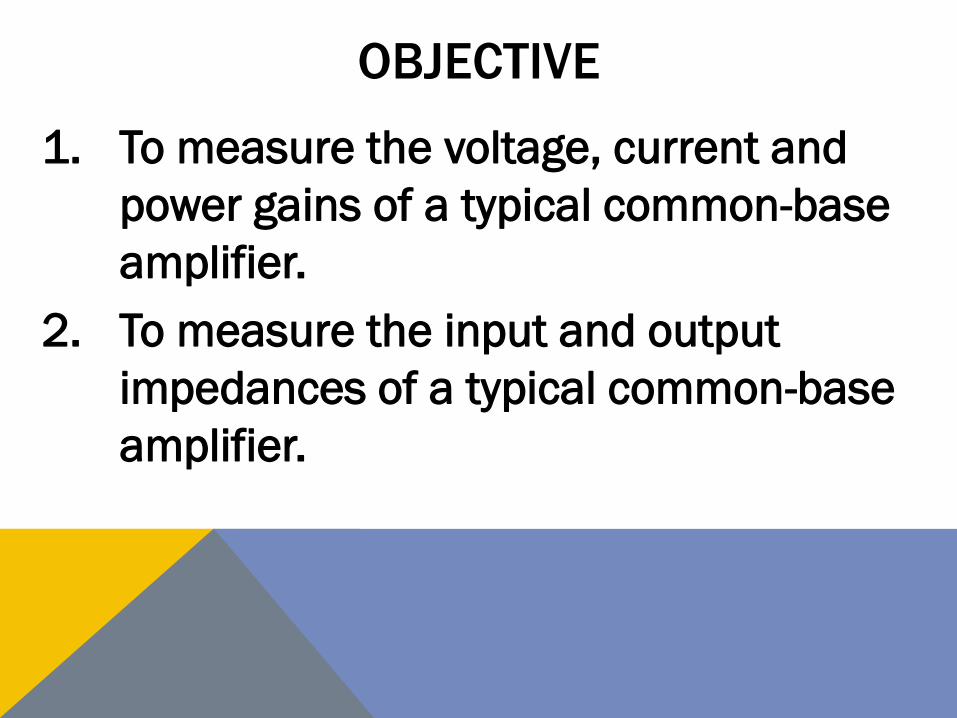
OBJECTIVE
1. To measure the voltage, current and
power gains of a typical common-base
amplifier.
2. To measure the input and output
impedances of a typical common-base
amplifier.

INTRODUCTION
• The next slide illustrates a common-
base amplifier.
• The base is biased by a voltage divider
and the emitter is biased through an
emitter resistor.

SCHEMATIC OF A COMMON-BASE AMP.
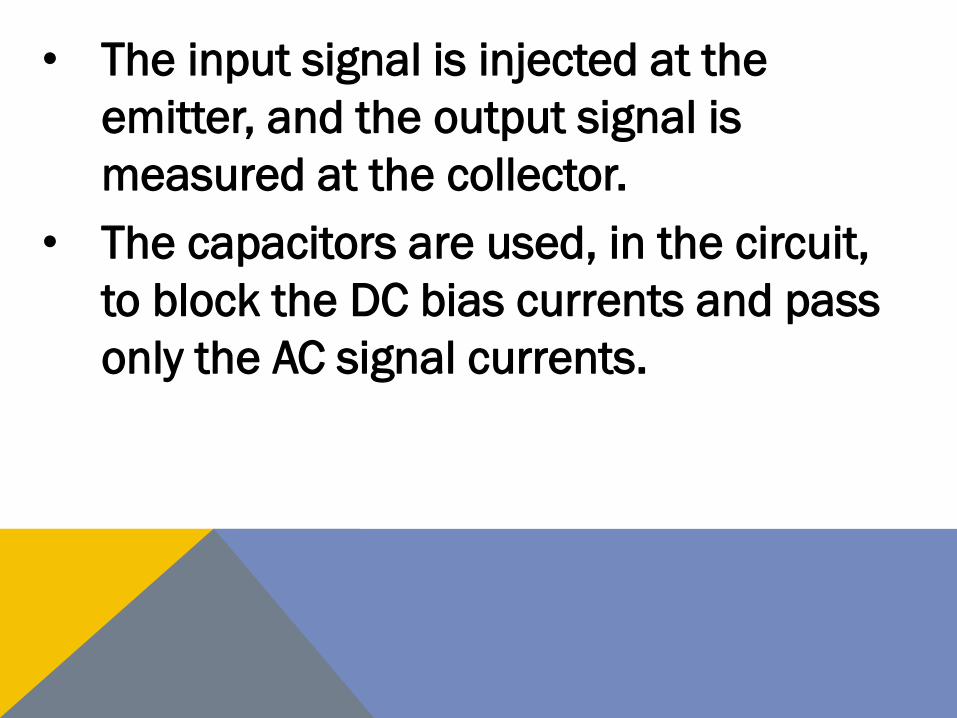
• The input signal is injected at the
emitter, and the output signal is
measured at the collector.
• The capacitors are used, in the circuit,
to block the DC bias currents and pass
only the AC signal currents.
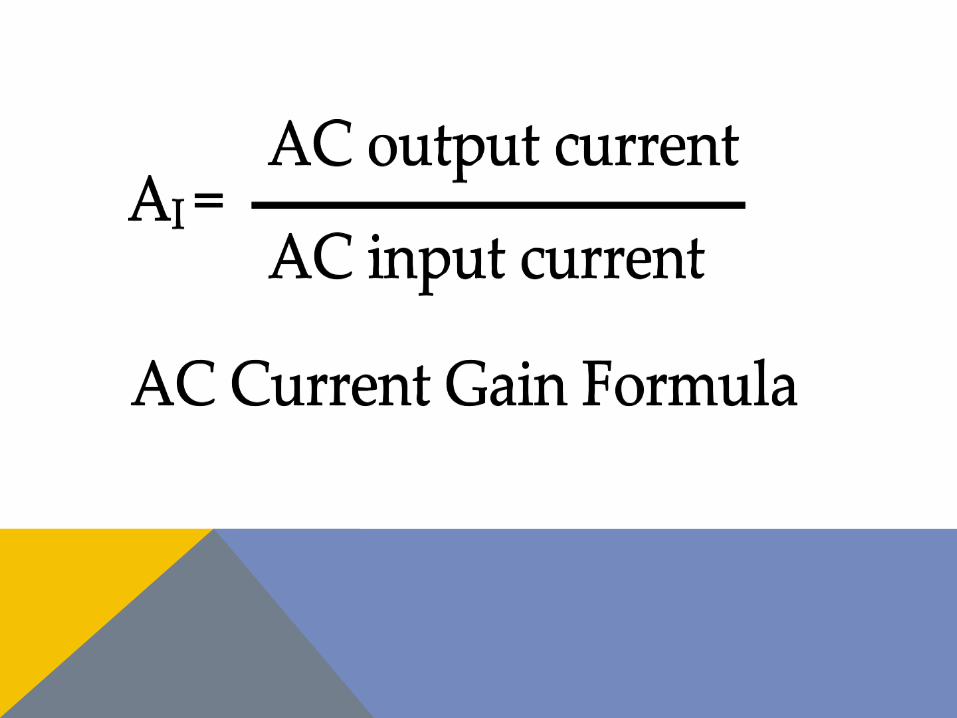
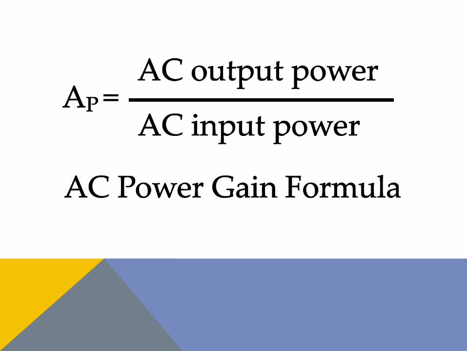
• In this experiment, we will be calculating,
using measured values, the Voltage Gain
AV, Current Gain AI and the Power Gain AP.
• The following slide illustrates the
formulas for the gains mentioned above,
• Later we will use these formulas to
compare the three basic amplifier
configurations.
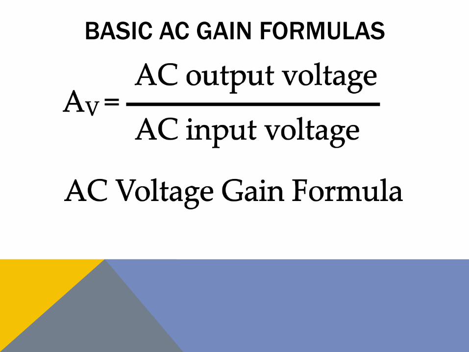
BASIC AC GAIN FORMULAS
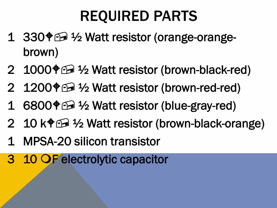
REQUIRED PARTS
1 330W, ½ Watt resistor (orange-orange-
brown)
2 1000W, ½ Watt resistor (brown-black-red)
2 1200W, ½ Watt resistor (brown-red-red)
1 6800W, ½ Watt resistor (blue-gray-red)
2 10 kW, ½ Watt resistor (brown-black-orange)
1 MPSA-20 silicon transistor
3 10 mF electrolytic capacitor
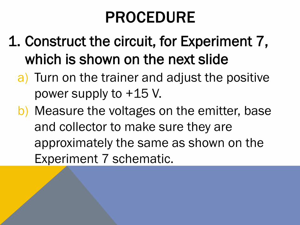
PROCEDURE
1. Construct the circuit, for Experiment 7,
which is shown on the next slide
a) Turn on the trainer and adjust the positive
power supply to +15 V.
b) Measure the voltages on the emitter, base
and collector to make sure they are
approximately the same as shown on the
Experiment 7 schematic.
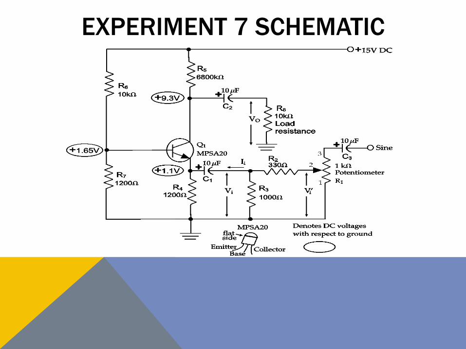
EXPERIMENT 7 SCHEMATIC

EXPERIMENT 7, CIRCUIT PICTORIAL
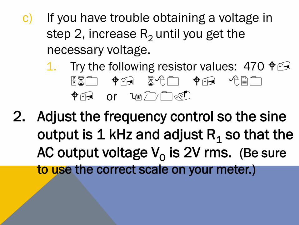
c) If you have trouble obtaining a voltage in
step 2, increase R2 until you get the
necessary voltage.
1. Try the following resistor values: 470 W,
560 W, 680 W, 820
W, or 910.
2. Adjust the frequency control so the sine
output is 1 kHz and adjust R1 so that the
AC output voltage VO is 2V rms. (Be sure
to use the correct scale on your meter.)
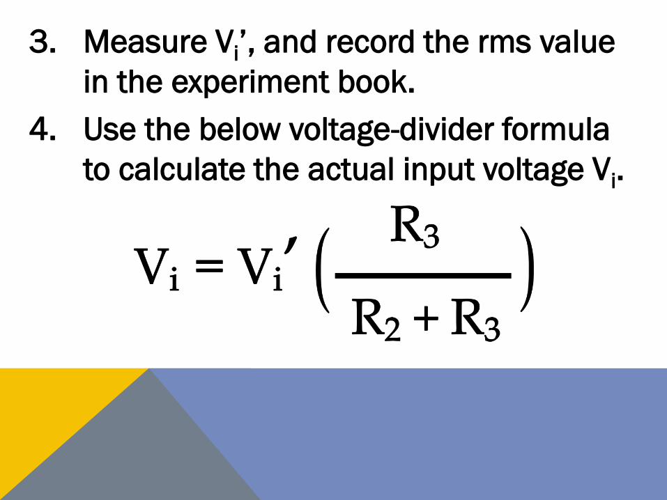
3. Measure Vi’, and record the rms value
in the experiment book.
4. Use the below voltage-divider formula
to calculate the actual input voltage Vi.
a) Record the calculated rms value in the
experiment book.
5. Calculate the voltage gain of the
amplifier using the formula VO/Vi.
a) Record the calculated value of the voltage
gain in the experiment book.
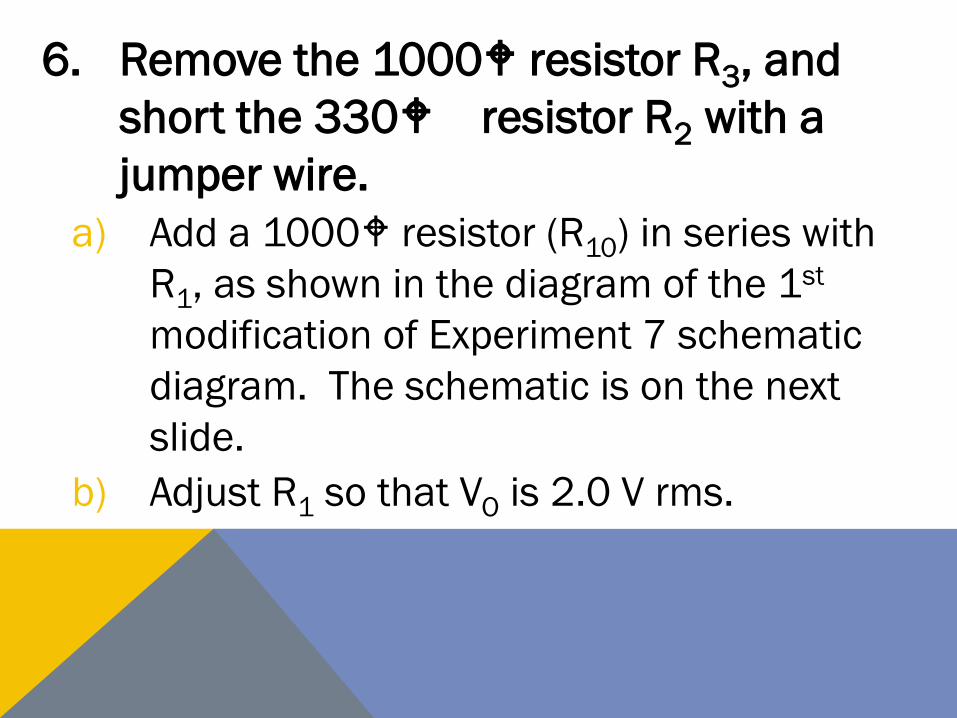
6. Remove the 1000W resistor R3, and
short the 330W resistor R2 with a
jumper wire.
a) Add a 1000W resistor (R10) in series with
R1, as shown in the diagram of the 1st
modification of Experiment 7 schematic
diagram. The schematic is on the next
slide.
b) Adjust R1 so that VO is 2.0 V rms.
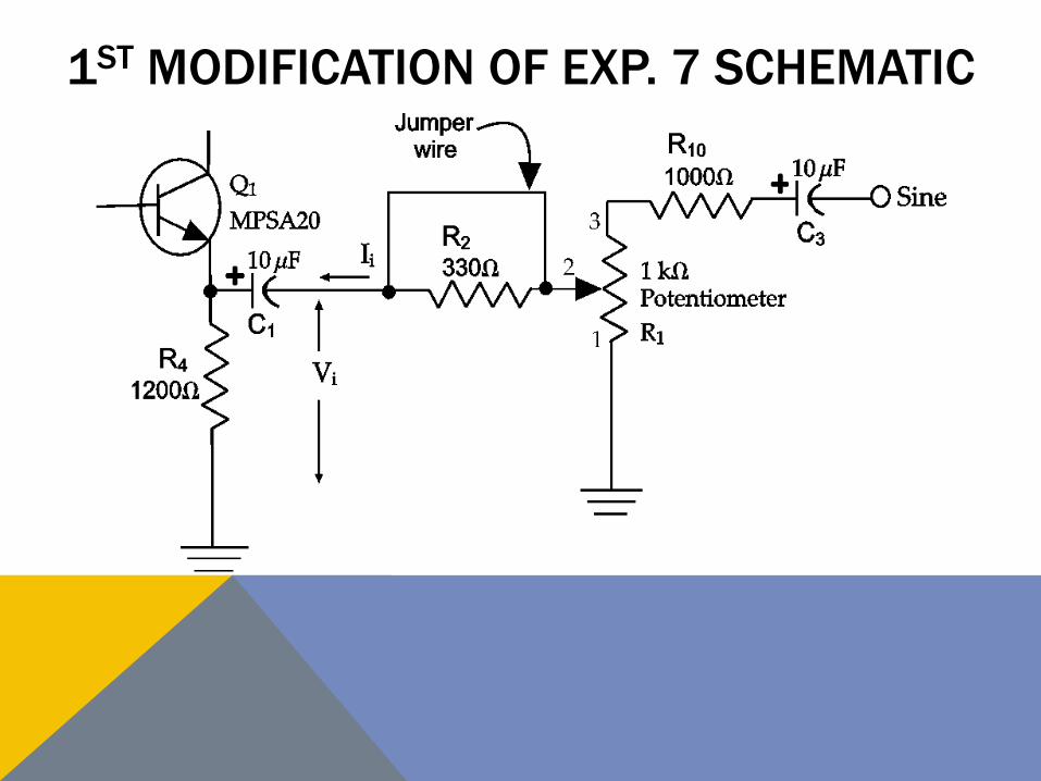
1ST MODIFICATION OF EXP. 7 SCHEMATIC

EXP. 7, 1ST MOD. CIRCUIT PICTORIAL
7. Remove the jumper wire across R2, and
measure the output voltage VO.
a) Record the rms value in the experiment
book.
8. Determine the input voltage required to
get the output voltage you recorded in
step 7.
a) Use the voltage gain you recorded in step 5.
b) Record the input voltage (rms value) in the
experiment book.
9. The voltage drop of R2 is the
difference between the voltage you
recorded in step 4 and the voltage
you calculated in step 8.
a) Record the input voltage (rms value) in the
experiment book.
10. The input current is the voltage across
resistor R2 divided by the resistance
value if R2.
a) Calculate the input current, using the
voltage you recorded in step 9.
b) Record the current value in the experiment
book. Ii = mA rms
11. The output voltage is the output voltage
VO divided by the load resistance RL
(10kW).
a) Calculate the output current, using the
voltage you recorded in step 7.
b) IO = mA rms. (Value may be in mA
rms.)
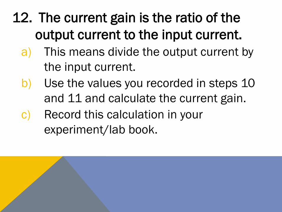
12. The current gain is the ratio of the
output current to the input current.
a) This means divide the output current by
the input current.
b) Use the values you recorded in steps 10
and 11 and calculate the current gain.
c) Record this calculation in your
experiment/lab book.
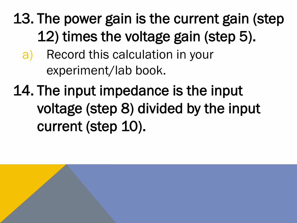
13. The power gain is the current gain (step
12) times the voltage gain (step 5).
a) Record this calculation in your
experiment/lab book.
14. The input impedance is the input
voltage (step 8) divided by the input
current (step 10).

a) Use the values you recorded in steps 8
and 10 and calculate the input
impedance.
b) Record this calculation in your
experiment/lab book.
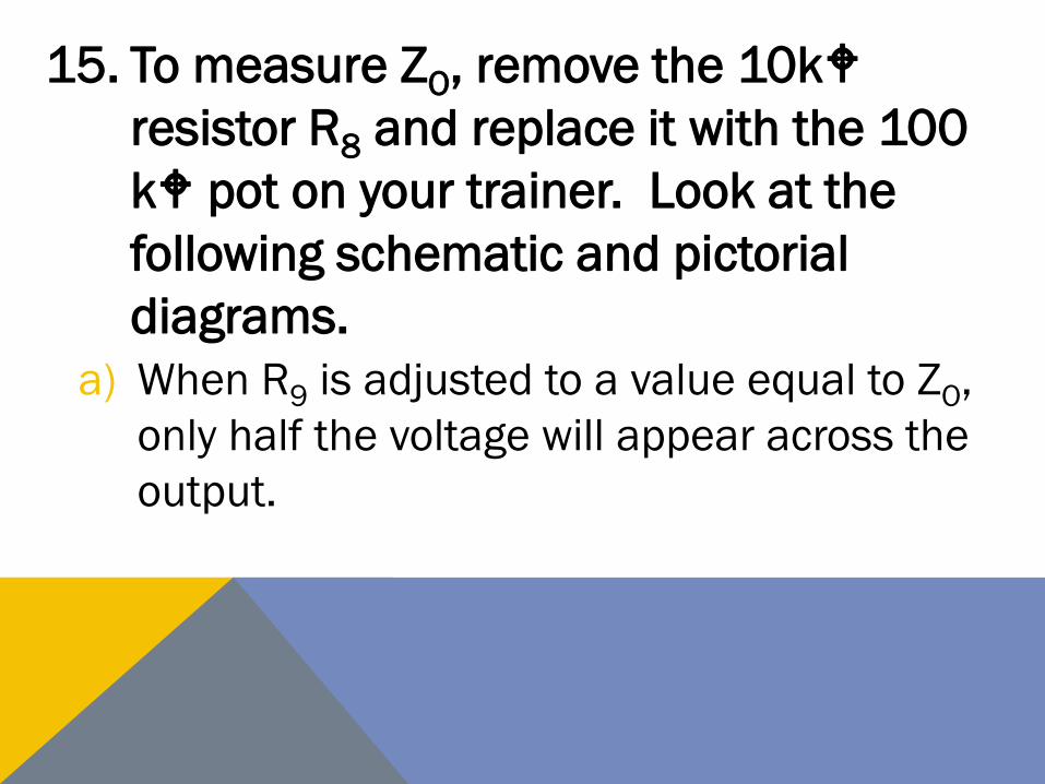
15. To measure ZO, remove the 10kW
resistor R8 and replace it with the 100
kW pot on your trainer. Look at the
following schematic and pictorial
diagrams.
a) When R9 is adjusted to a value equal to ZO,
only half the voltage will appear across the
output.
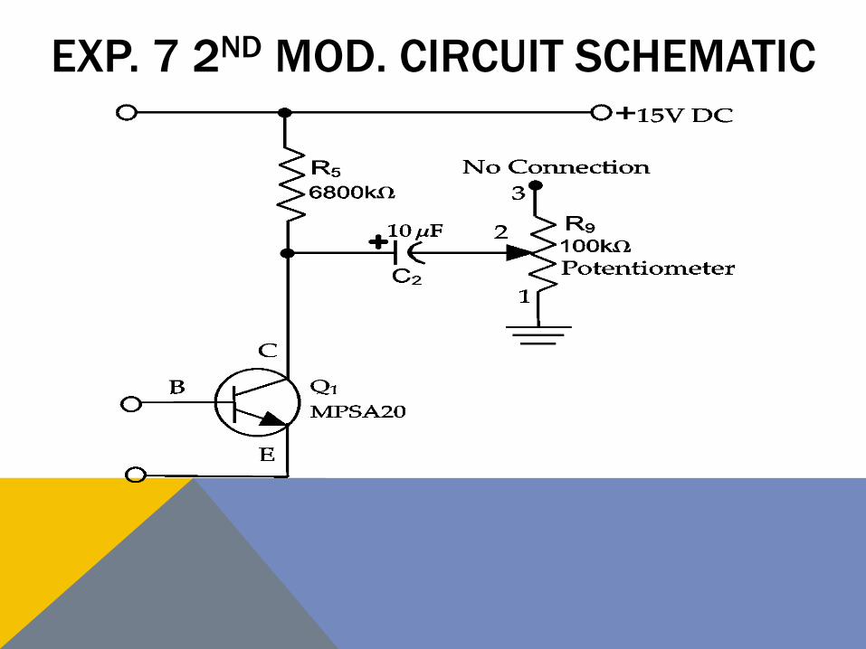
EXP. 7 2ND MOD. CIRCUIT SCHEMATIC
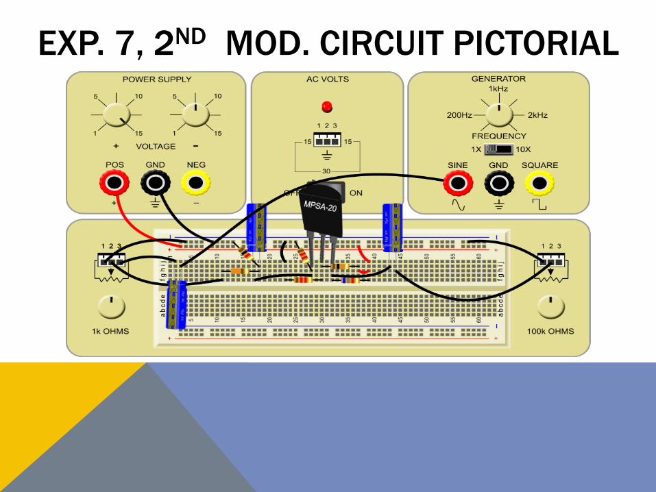
EXP. 7, 2ND MOD. CIRCUIT PICTORIAL
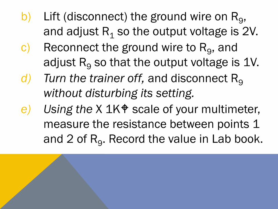
b) Lift (disconnect) the ground wire on R9,
and adjust R1 so the output voltage is 2V.
c) Reconnect the ground wire to R9, and
adjust R9 so that the output voltage is 1V.
d) Turn the trainer off, and disconnect R9
without disturbing its setting.
e) Using the X 1KW scale of your multimeter,
measure the resistance between points 1
and 2 of R9. Record the value in Lab book.
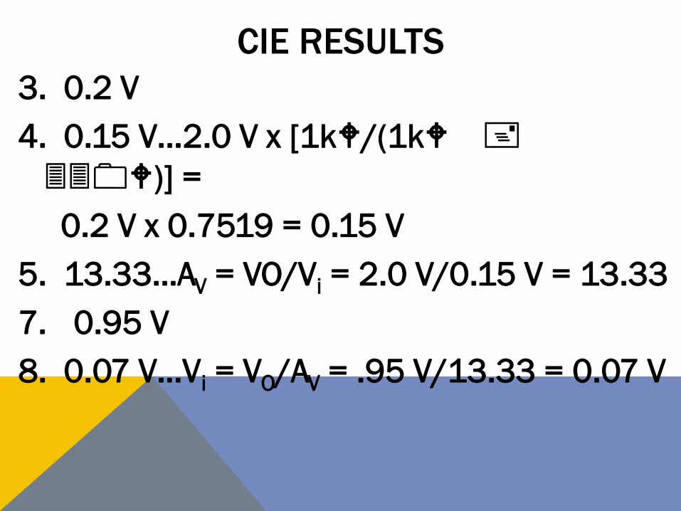
CIE RESULTS
3. 0.2 V
4. 0.15 V…2.0 V x [1kW/(1kW +
330W)] =
0.2 V x 0.7519 = 0.15 V
5. 13.33…AV = VO/Vi = 2.0 V/0.15 V = 13.33
7. 0.95 V
8. 0.07 V…Vi = VO/AV = .95 V/13.33 = 0.07 V
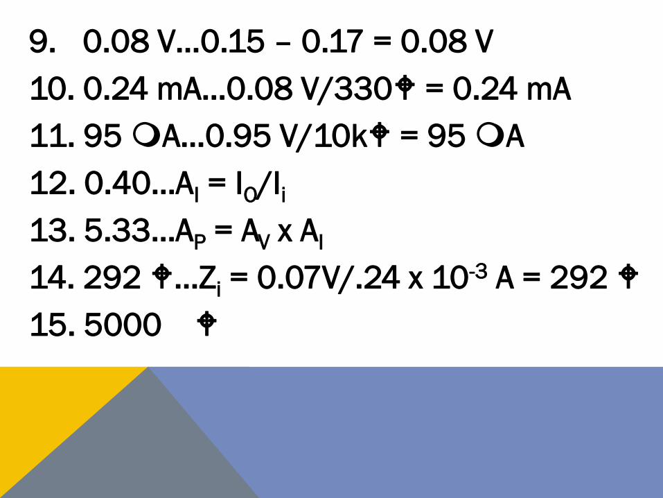
9. 0.08 V…0.15 – 0.17 = 0.08 V
10. 0.24 mA…0.08 V/330W = 0.24 mA
11. 95 mA…0.95 V/10kW = 95 mA
12. 0.40…AI = IO/Ii
13. 5.33…AP = AV x AI
14. 292 W…Zi = 0.07V/.24 x 10-3 A = 292 W
15. 5000 W
FINAL DISCUSSION
• Since the voltage gain of the amplifier
was so high, it was not possible to
measure the input voltage directly. Thus
we used a voltage divider consisting of
the 330 W resistor R2 and the 1000 W
resistor R3.

Then we could measure the voltage
going into the divider Vi’(step 3), and the
voltage coming out of the divider, Vi
(step 4). We were then able to calculate
the voltage gain (step 5).
• We then measured the input current
indirectly.
• We first adjusted the input voltage so the
output voltage was 2V (step 6).
• Then we inserted a 330 W resistor in
series with the input (step 7), and
measured the output voltage. This let us
use the voltage gain, of the amplifier. to
calculate the voltage drop across the 330
W resistor (steps 8 and 9).

• We could then calculate the current through
the 300 W resistor (step 10), since we knew
the voltage across the 300 W resistor.
• Since the 330 W resistor was in series
with the input of the amplifier, the
current through the 330 W resistor was
the same as the current through the
input of the amplifier (step 10).
• The previous steps of this experiment
gave us the voltage gain, input voltage,
output voltage and input current.
• We were then able to calculate the
current gain (step 12), power gain (step
13), and the input impedance (step 14).
• We measured the output impedance by
simply loading the output with the 100k
W potentiometer until the output voltage
was half its unloaded value.
• At this point, half the voltage was across
the output impedance of the amplifier and
half was dropped across the load resistor
(the 100 kW potentiometer).
• The measured resistance of the 100 kW
potentiometer at this setting was equal
to the output impedance of the amplifier.
While your results may differ substantially from
ours (due to variations from one transistor to
another), your conclusions should be in the same
general range as those reached in the lab at CIE.
To summarize our results, we recorded the
following: a voltage gain of 13.3; a current
gain of 0.4; a power gain of 5.33; an input
impedance of 292 W; and an output
impedance of 5000 W.

QUESTIONS?

RESOURCES
Casebeer, J.L., Cunningham, J.E. (2001).
Lesson 1430: Transistors, Part 1.
Cleveland: Cleveland Institute of
Electronics.

THE END
Developed and Produced by the
Instructors in the CIE Instruction
Department.
© Copyright 10/2012
All Rights Reserved / Oct. 2012