![gkbMªksdkcZu - NCERT · 2012. 3. 6. · gkbMªksdkcZu 363 lajpuk I rFkk II dk v.kq lw=k leku gS] ¯drq DoFkukad rFkk vU; xq.kèkeZ fHkUu gSaA blh izdkj lajpukvksa III, IV rFkk V](https://static.fdocuments.net/doc/165x107/60d72a2f12f4150f490151cd/gkbmksdkczu-ncert-2012-3-6-gkbmksdkczu-363-lajpuk-i-rfkk-ii-dk-vkq-lwk.jpg)
fo|qr rFkk bysDVªkfud ekud · bysfDVªdy rFkk bysDVªkfud ekud fo ... A magneto-optic trap has...
10
fo| q r rFkk by s DV ª kfud ekud
Transcript of fo|qr rFkk bysDVªkfud ekud · bysfDVªdy rFkk bysDVªkfud ekud fo ... A magneto-optic trap has...

fo|qr rFkk bysDVªkfud ekud

bysfDVªdy rFkk bysDVªkfud ekud
fo|qr vkSj bySDVªkWfud ekud foHkkx fofHkUu fo|qr] bySDVªkWfud vkSj pqEcdh; izkpyksa ds izkFkfed vkSj lSds.Mjh LVS.MMZ] ,l vkbZ ;wfuV dks Kkr djus] LFkkiu] vuqj{k.k vkSj foLrkj.k esa lfØ; :i ls lyaXu gSA foHkkx fofHkUu m|ksxksa] vuqla/kkuksa vkSj fodflr iz;ksx'kkykvksa] j{kk iz;ksx'kkykvksa rFkk Hkkjrh; varfj{k vuqla/kku laxBu bR;kfn dks vuqekxZ.kh;rk iznku djrk gSA ;g foHkkx vUrjkZ"Vªh; varrqZyukvksa] f}i{kh vkSj fuiq.krk ijh{k.k dk;ZØeksa esa Hkh lfØ; :Ik ls layXu gSA bl vof/k esa foHkkx dh dqN egŸoiw.kZ miyfC/k;ka gSa tks fuEufyf[kr gSaA
i. Hkkjrh; izknsf'kd usohxs'ku flLVe (IRNSS) ds fy, Rb ijek.kq ?kM+h dks fodflr djus ds fy, SAC-NPL la;qDr ifj;kstuk ds vUrxZr jk"Vªh; HkkSfrd iz;ksx'kkyk esa Rb ijek.kq ?kM+h ds fQft+Dl iSdst+ lQyrkiwoZd fodflr fd;k x;k gSA
ii. ge Cs Qkm.Vsu DykWd dks ,u ih ,y Hkkjr esa fodflr dj jgs gSaA gky esa gh VªSIM Cs ,Vksfed DykmM lfgr ,d eSXusVks&vkfIVd VSªi dk lQyrkiwoZd izn'kZu fd;k x;k gSA
iii. eksckby VsyhQksu usVodZ dk iz;ksx djrs gq, Vsyh DykWd fjlhoj ds u, izk:Ik (Version) dk fodkl fd;k x;k gS vkSj ;g rduhdh tkudkjh ,d m|ksx@laxBu dks gLrkarfjr dj nh x;h gSA izks- lehj ds czgepkjh] egk funs'kd lh ,l vkbZ vkj us 28 tqykbZ] 2009 dks tu lkekU; ds bLrseky ds fy, bl u, izk:i dk vkSipkfjd :i ls mn~?kkVu fd;kA
iv. 3X600 oksYVl vkSj 3X120 Amps ds fy, ,d ubZ cgq LFkku ¼eYVh iksft'ku½ ikoj ,oa ÅtkZ ehVj va'kkadu@ijh{k.k csap dks izfrLFkkfir fd;k x;k gSA
v. fuEu ean oksYVstksa ij AC-DC VªkalQj ekud dh eq[; rqyuk EUROMET EM-EII dh vafre fjiksVZ ls irk pyrk gS fd ,u ih ,y vkbZ vUrrqZyuk ds fy, vkjafHkd iz;ksx’kkyk }kjk fy, x, rqyuk lUnHkZ eku ds dkQh djhc gSA
vi. 11 vkSj 12 ekpZ] 2010 dks DC mPp oksYVst ij nwljk ihvj iqujh{k.k djk;k x;k FkkA fo|eku rhu CMCs esa la'kks/ku fd;k x;k vkSj DC mPp /kkjk ds fy, ikap u, CMCs dk KRISS dksfj;k ds vUrjkZ"Vªh; [;kfr izkIr rduhdh fo'ks"kKksa }kjk vuqeksnu fd;k x;kA
vii. ,aVhuk o`f) % 6-10 dB o VSWR ≤ 1-6 Qhpj lfgr 1 ls 18 GHz dh vko`fŸk lhek ds fy, ,d TEM gkWuZ ,afVuk dh ;qfDr rFkk fuekZ.k fd;k x;kA
viii. RkjaxiFkd iz.kkyh esa VNA-vk/kkfjr izfrck/kk ekiu lqfo/kk ¼baihMsal estjesaV QsflfyVh½ ds laLFkkiu ds fy, Ka-band
(26.5 to 40 GHz) vkSj Q-band (33 to 50 GHz) ÝhDosalh jsat esa ifj’kq) osoxkbM [k.Mksa vkSj ¶y'k 'kkVZl~ dks Lons'k esa gh fodflr fd;k x;k gSA
electrical and electronic standards
The electrical and electronics standards division is actively involved in the realization, establishment, maintenance and dissemination of SI unit, primary and secondary standards of various electrical, electronic and magnetic parameters. This division provides traceability to the various industries, R & D laboratories, defence labs and ISRO etc. The division is also actively involved in the international intercomparison, bilateral and proficiency testing programmes.
Some of the important achievements of the division during this period are listed below:
i. A Physics Package of Rb atomic clock has been successfully developed at National Physical Laboratory under the SAC-NPL joint project on the development of Rb Atomic clock for Indian Regional Navigation System (IRNSS).
ii. We have been developing a Cs fountain clock at NPL India. A magneto-optic trap has been successfully demonstrated with a trapped Cs atomic cloud recently.
iii. New Version of Teleclock Receiver using mobile telephone network has been developed and know –how has been transferred to one company. This new version has formally been launched for public use by Prof. Samir K. Brahmchari, DG CSIR on 28 July 2009.
iv. A new Multi position power and energy meter calibration/test bench has been installed for 3X600 Volts and 3X120 Amps.
v. The final report on the “Key Comparison EUROMET.EM- K11 on AC-DC transfer standards at low voltages”, shows that the results of NPLI are very close to the comparison reference value taken by the pilot laboratory for the intercomparison.
vi. 2nd peer review of DC High Voltage was conducted on 11th and 12th March 2010. Exsiting three CMCs were improved and five new CMCs for DC high current were approved by international renowned technical expert from KRISS Korea.
vii. A TEM horn antenna has been designed and fabricated for the frequency range 1 to 18 GHz with the features of antenna gain: 6-10 dB and VSWR ≤ 1.6.
viii. Precision waveguide sections and flush shorts in Ka-band (26.5 to 40 GHz) and Q-band (33 to 50 GHz) frequency range have been indigenously developed for the establishment of VNA-based impedance measurement facility in waveguide system.
bysfDVªdy rFkk bysDVªkfud ekud
Annual Report 2009-1032 jk"Vªh; HkkSfrd iz;ksx'kkyk
Time and Frequency StandardsA Physics Package of Rb atomic clock has
been successfully developed at National Physical Laboratory under the SAC-NPL joint project on the development of Rb Atomic clock for Indian Regional Navigation System (IRNSS). A MoU has also been signed with the Russian company for developing Rb bulbs and cells of high quality which can withstand vibration, shock, radiation and other stringent tests, making them worthy of use in high pressure and vacuum conditions in space. The vacuum system for developing Rb isotopic cells and bulbs at NPL is under development.
Fig. 2.1 Current Status of Physics package of Rb clock (SAC-NPL Project)
Fig. 2.3 Status of Time Scale UTC(NPLI) maintained by NPL
Fig. 2.2 MOT setup of Laser Cooled Cs Fountain Project
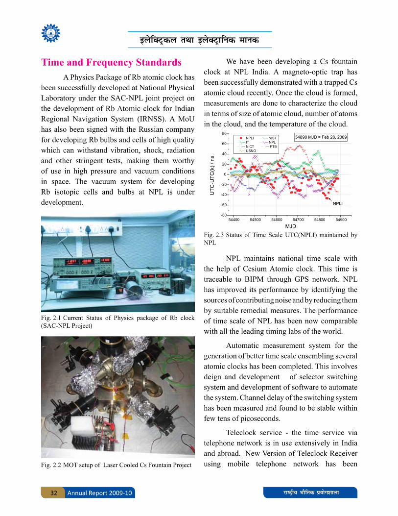
We have been developing a Cs fountain clock at NPL India. A magneto-optic trap has been successfully demonstrated with a trapped Cs atomic cloud recently. Once the cloud is formed, measurements are done to characterize the cloud in terms of size of atomic cloud, number of atoms in the cloud, and the temperature of the cloud.
NPL maintains national time scale with the help of Cesium Atomic clock. This time is traceable to BIPM through GPS network. NPL has improved its performance by identifying the sources of contributing noise and by reducing them by suitable remedial measures. The performance of time scale of NPL has been now comparable with all the leading timing labs of the world.
Automatic measurement system for the generation of better time scale ensembling several atomic clocks has been completed. This involves deign and development of selector switching system and development of software to automate the system. Channel delay of the switching system has been measured and found to be stable within few tens of picoseconds.
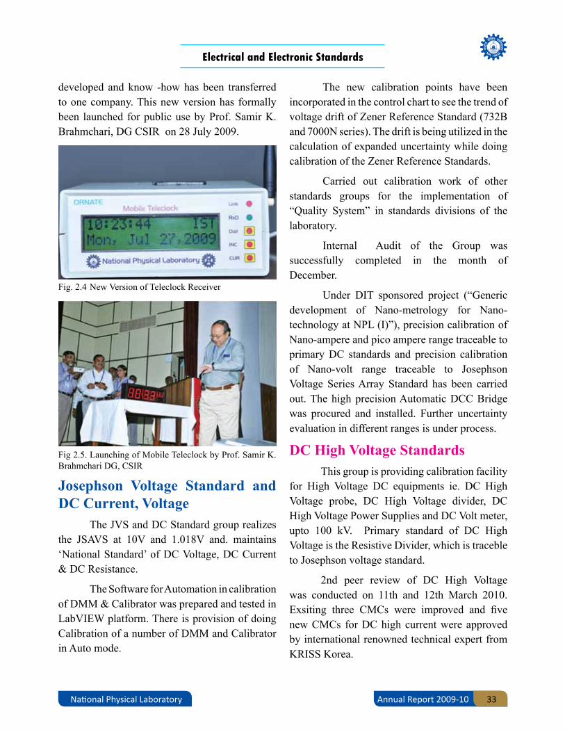
Teleclock service - the time service via telephone network is in use extensively in India and abroad. New Version of Teleclock Receiver using mobile telephone network has been
Electrical and Electronic Standards
Annual Report 2009-10 33National Physical Laboratory
Fig. 2.4 New Version of Teleclock Receiver
Fig 2.5. Launching of Mobile Teleclock by Prof. Samir K. Brahmchari DG, CSIR
developed and know -how has been transferred to one company. This new version has formally been launched for public use by Prof. Samir K. Brahmchari, DG CSIR on 28 July 2009.
Josephson Voltage Standard and DC Current, Voltage
The JVS and DC Standard group realizes the JSAVS at 10V and 1.018V and. maintains ‘National Standard’ of DC Voltage, DC Current & DC Resistance.
The Software for Automation in calibration of DMM & Calibrator was prepared and tested in LabVIEW platform. There is provision of doing Calibration of a number of DMM and Calibrator in Auto mode.
The new calibration points have been incorporated in the control chart to see the trend of voltage drift of Zener Reference Standard (732B and 7000N series). The drift is being utilized in the calculation of expanded uncertainty while doing calibration of the Zener Reference Standards.
Carried out calibration work of other standards groups for the implementation of “Quality System” in standards divisions of the laboratory.
Internal Audit of the Group was successfully completed in the month of December.
Under DIT sponsored project (“Generic development of Nano-metrology for Nano-technology at NPL (I)”), precision calibration of Nano-ampere and pico ampere range traceable to primary DC standards and precision calibration of Nano-volt range traceable to Josephson Voltage Series Array Standard has been carried out. The high precision Automatic DCC Bridge was procured and installed. Further uncertainty evaluation in different ranges is under process.
DC High Voltage StandardsThis group is providing calibration facility
for High Voltage DC equipments ie. DC High Voltage probe, DC High Voltage divider, DC High Voltage Power Supplies and DC Volt meter, upto 100 kV. Primary standard of DC High Voltage is the Resistive Divider, which is traceble to Josephson voltage standard.
2nd peer review of DC High Voltage was conducted on 11th and 12th March 2010. Exsiting three CMCs were improved and five new CMCs for DC high current were approved by international renowned technical expert from KRISS Korea.

bysfDVªdy rFkk bysDVªkfud ekud
Annual Report 2009-1034 jk"Vªh; HkkSfrd iz;ksx'kkyk
AC Power and Energy StandardAC Power & Energy Standard maintains
national standard of AC Power & Energy and is actively involved in the dissemination of traceability throughout the country.
Peer Review for the activity was held in Feb. 2009 and improvement in measurement uncertainty was sent to APMP. All the proposed CMC’s have been cleared by QS reviewer and APMP TC chair of EM has informed that the Intra Regional review of CMC’s is nearly completion and will be submitted to JCRB for Inter regional review in early September 2010.
Various clauses for testing of AC/DC abnormal magnetic influences have been included in IS specifications with a view to control energy theft.
A new Multi position power and energy meter calibration/test bench has been installed for 3X600 Volts and 3X120 Amps.
Disputed energy meters were received from court of law/Electricity boards.
These were tested and analysed for tampering and energy theft.
AC High Current and High Voltage Standards
This section is maintaining National Standards of AC High Current and High Voltage Ratios at power frequencies (50Hz) by using Reference Standard Current Transformers and Reference Standard High Voltage Ratio Measuring System. Calibration services were provided for the calibration of Current Transformers, Current Transformer Testing Sets, Clamp Meters, CT Burdens and for Voltage Transformers, Voltage Transformer Testing Sets, HV Probes, Electrostatic
Voltmeters (ESVMs), HV Break Down Test Sets and Voltage Transformer Burdens etc. As many as 80 Calibration Certificates were issued to the electrical manufacturers and utilities.
The National Standard of AC High Current Ratio Measuring System upto 5000A/1A, 5A is shown in Fig. 2.6.
Fig. 2.6 The National Standard of AC High Current Ratio Measuring System upto 5000A/1A, 5A
Fig. 2.7 The National Standard of AC High Voltage Ratio up to 100kV/100V comprising of the Compressed Gas Capacitor, Air Capacitor & the Electronic Voltage Divider (EVD)
The National Standard of AC High Voltage Ratio up to 100kV/100V comprising of the Compressed Gas Capacitor, Air Capacitor & the Electronic Voltage Divider (EVD) is shown in Fig.2.7.
Electrical and Electronic Standards
Annual Report 2009-10 35National Physical Laboratory
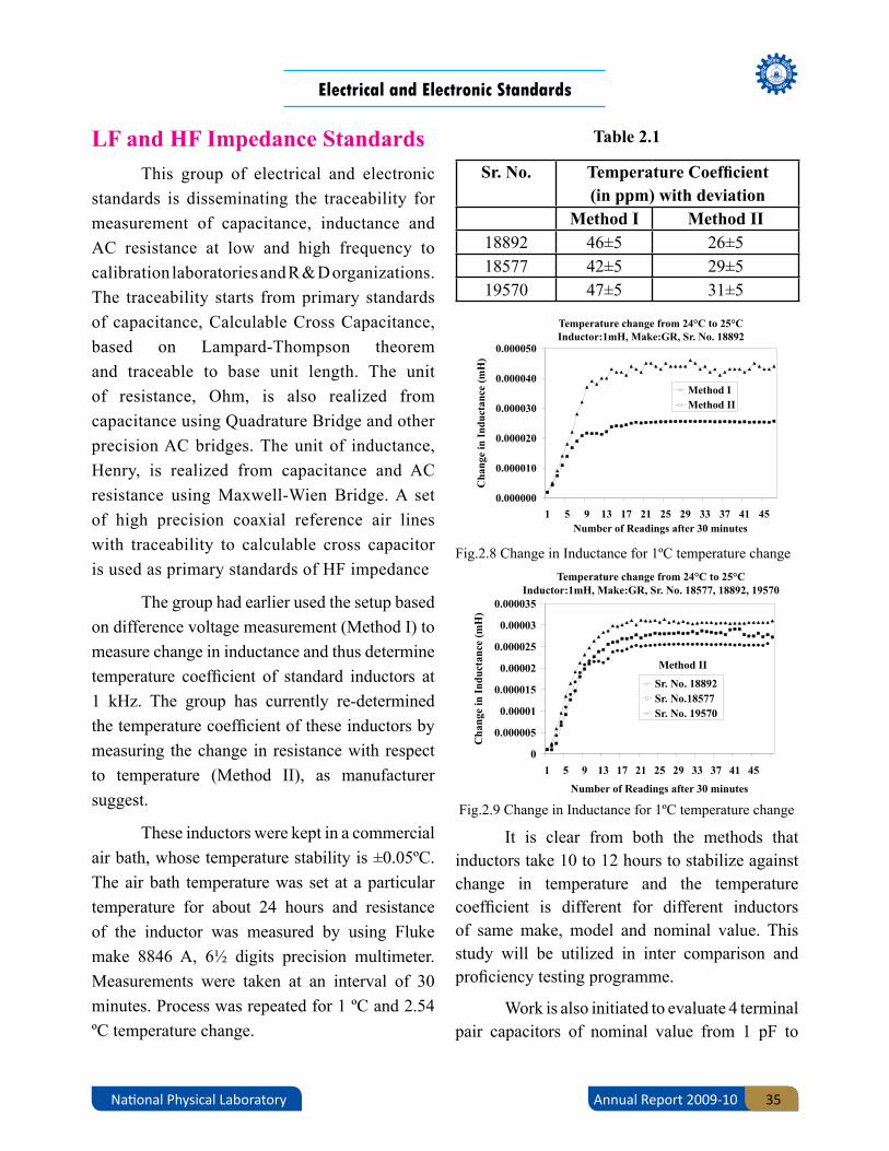
Fig.2.8 Change in Inductance for 1ºC temperature change
Fig.2.9 Change in Inductance for 1ºC temperature change
LF and HF Impedance StandardsThis group of electrical and electronic
standards is disseminating the traceability for measurement of capacitance, inductance and AC resistance at low and high frequency to calibration laboratories and R & D organizations. The traceability starts from primary standards of capacitance, Calculable Cross Capacitance, based on Lampard-Thompson theorem and traceable to base unit length. The unit of resistance, Ohm, is also realized from capacitance using Quadrature Bridge and other precision AC bridges. The unit of inductance, Henry, is realized from capacitance and AC resistance using Maxwell-Wien Bridge. A set of high precision coaxial reference air lines with traceability to calculable cross capacitor is used as primary standards of HF impedance
The group had earlier used the setup based on difference voltage measurement (Method I) to measure change in inductance and thus determine temperature coefficient of standard inductors at 1 kHz. The group has currently re-determined the temperature coefficient of these inductors by measuring the change in resistance with respect to temperature (Method II), as manufacturer suggest.
These inductors were kept in a commercial air bath, whose temperature stability is ±0.05ºC. The air bath temperature was set at a particular temperature for about 24 hours and resistance of the inductor was measured by using Fluke make 8846 A, 6½ digits precision multimeter. Measurements were taken at an interval of 30 minutes. Process was repeated for 1 ºC and 2.54 ºC temperature change.
Sr. No. Temperature Coefficient (in ppm) with deviation
Method I Method II18892 46±5 26±518577 42±5 29±519570 47±5 31±5
It is clear from both the methods that inductors take 10 to 12 hours to stabilize against change in temperature and the temperature coefficient is different for different inductors of same make, model and nominal value. This study will be utilized in inter comparison and proficiency testing programme.
Work is also initiated to evaluate 4 terminal pair capacitors of nominal value from 1 pF to
Table 2.1

bysfDVªdy rFkk bysDVªkfud ekud
Annual Report 2009-1036 jk"Vªh; HkkSfrd iz;ksx'kkyk
1000 pF to be used as high frequency impedance standards.
LF and HF Voltage, Current and RF Power Standards
Traceability of thermal voltage converters covering voltage range from 250 mV to 1000 V & frequency from 10 Hz to 1 MHz has been re-established to the primary standard of LF voltage. Traceability of thermal current converters covering the current range from 1 mA to 20 A has been re-established to the primary standard of LF current in the frequency range 10 Hz to 10 kHz.
RF Power Standards:
Successfully installed the new thermopile in the coaxial line of the microcalorimeter. To evaluate coaxial microcalorimeter correction factors, designed and developed RF short and open using an old coaxial thermistor mount.
Coaxial microcalorimeter lines losses have been evaluated which gave the attenuation factor of the calorimeter line. With all these results we have calculate the correction factors of the calorimeter by practically estimating ‘eL’, which is an additional thermopile e.m.f for an N type coaxial thermistor mount due to RF losses.
RF Voltage Standards:
Traceability of high frequency thermal converters against the primary standard of HF voltage based on calorimetric principles has been re-established in the voltage range 1V to 50 Volt upto 1000 MHz.
Intercomparison:
The final report on the “Key Comparison EUROMET.EM- K11 on AC-DC transfer standards at low voltages”, shows that the
results of NPLI are very close to the comparison reference value taken by the pilot laboratory for the intercomparison as shown in the fig.2.10
Fig 2.10: Results of the intercomparison
Automation Softwares:
Submitted three softwares for copyright to IPMD, CSIR New Delhi vide NPL ref no. NPL/IPRM/CR/3/2009 dated 17/09/2009.Two softwares are for LF Voltage & Current, one for assigning AC-DC transfer difference to thermal voltage & current converters and micro potentiometers using thermal devices and other for calibrating precision AC calibrator.
Third software measures the resistivity of the superconducting materials in the temperature range of 12 K to 325 K for Superconductivity and Cryogenics DU#7.
Establishment of free space dielectric measurement technique
Free space dielectric measurement technique has been established for RF characterization of material sheets in 8.2 to 12.4 GHz range. The technique broadly comprises of a vector network analyzer Wiltron 37247B, two X-band horn antennas and the material sheet holder.

Electrical and Electronic Standards
Annual Report 2009-10 37National Physical Laboratory
Fig.2.11 X-band horn antennas with turn tables
Fig.2.12 Ka- and Q-band waveguide standards
The technique has been verified with Teflon dielectric sheet and used to characterize Plaster of Paris (CaSO4•H2O), white rigid Polyethylene foam and yellow flexible Polyurethane foam. The calculated dielectric properties along with their uncertainties are given in Table 2.2.
Development of Ka- and Q-band waveguide standards
Precision waveguide sections and flush shorts in Ka-band (26.5 to 40 GHz) and Q-band (33 to 50 GHz) frequency range have been
Table 2.2 - Dielectric properties in the X-band frequency range
Parameter / Material
Dielectric constant ε´ Dielectric Loss ε˝ Loss tangent tanδ
Range Uncertainty Range Uncertainty Range Uncertainty
Teflon 2.0551.882
0.0550.048
0.0980.004
0.0021.72E-04
0.0510.002
1.14E-044.78E-07
Plaster of Paris
MaxMin
2.0881.869
0.0360.031
0.0996.38E-04
0.0021.54E-04
0.0513.18E-04
8.25E-053.26E-08
White Foam
MaxMin
1.0321.004
0.0140.014
0.0283.70E-04
3.84E-042.79E-05
0.0283.65E-04
2.14E-051.19E-08
Yellow Foam
MaxMin
1.0751.011
0.0140.014
0.0400.003
0.0016.25E-05
0.0400.002
4.18E-072.1E-07
indigenously developed for the establishment of VNA-based impedance measurement facility in waveguide system. These precision sections and flush shorts will be used as standards of VNA calibration kit for the calibration of waveguide components in the above frequency range which will be traceable to Dimensional metrology.
Design and development of TEM horn antenna
A TEM horn antenna has been designed and fabricated for the frequency range 1 to 18 GHz with the features of antenna gain: 6-10 dB and VSWR ≤ 1.6. This is developed for the wide applications in Broad-band communication systems, electromagnetic compatibility (EMC) measurement, detection systems.

bysfDVªdy rFkk bysDVªkfud ekud
Annual Report 2009-1038 jk"Vªh; HkkSfrd iz;ksx'kkyk
Fig.2.13 The TEM horn antenna
Extension of the attenuation measurement range:
A frequency converter model 8852 and an existing attenuator & signal calibrator model VM-7 through the software are under installation to enhance the dynamic range and uncertainty of attenuation parameter. This will enable the attenuation calibration facility upto more than 100 dB with uncertainty ± 0.02dB/10dB in comparison to the existing 60 dB with uncertainty
± 0.02 dB/10 dB in the range of 10 MHz to 18 GHz.
Magnetic StandardsPreparation and properties of new multiferroic Hexaferrite Sr3Co2Fe24O41
Multiferroics with sufficient magnetoelectric coupling at room temperature and low magnetic fields are very important for various spintronics as well as sensor applications. Recently a Z-type hexaferrite (Sr3Co2Fe24O41) is reported to be one of such important multiferroic materials. In the present work we have prepared Sr3Co2Fe24O41 compounds at various sintering temperatures and measured its structural magnetic and dielectric properties. The samples were prepared using solid state reaction route and sol-gel route. Extra phases of some different ferrite phases (Y-type & others) were also detected in some of the prepared samples. We have further planned to study the effect of additives Bi2O3, CuO and metallic silver on the preparation of these hexaferrite samples. The synthesis and the measurements on these samples are in progress.
![,sfrgkfld ’kgjksa uxjksa rFkk ’kgjh {ks=ksa ds cpko rFkk · PDF file,sfrgkfld ’kgjksa] uxjksa rFkk ’kgjh {ks=ksa ds cpko rFkk ... sA ,sfrgkfld uxjk rFkk ’kgjh {ks=ksa ,oa](https://static.fdocuments.net/doc/165x107/5a79c7507f8b9a9b4d8cf1e4/sfrgkfld-kgjksa-uxjksa-rfkk-kgjh-ksksa-ds-cpko-rfkk-sfrgkfld-kgjksa.jpg)

![Hkkjrh; ekud C;wjksokf"kZd fjiksVZ ANNUAL REPORT 2014-15 Hkkjrh; ekud C;wjks BUREAU OF INDIAN STANDARDS ekud Hkou] 9 cgknqj'kkg t++Qj ekxZ] ubZ fnYyh&110002 Manak Bhavan, 9 Bahadur](https://static.fdocuments.net/doc/165x107/5e75c6be62d6ef0e3a4a7d9f/hkkjrh-ekud-cwjks-okfkzd-fjiksvz-annual-report-2014-15-hkkjrh-ekud-cwjks.jpg)


![[kaM - National Council of Educational Research and …izko`Qfrd ladV rFkk vkink,¡ 83 rFkk Hkwfe dh dherksa osQ dkj.k rFkk rVksa ij cM+s uxjksa ,oa canjxkgksa] tSls& eqacbZ rFkk psUubZ](https://static.fdocuments.net/doc/165x107/5e5da093aaa1d830d2201ec2/kam-national-council-of-educational-research-and-izkoqfrd-ladv-rfkk-vkink.jpg)

![2015-16 - CMPDI€¦ · fo"k;&lwph Øe lañ fo"k; i`"B lañ 1- 2015&2016 ds nkSjku izcUèku 1 2- 13-06-2016 ds vuqlkj funs'kd eaMy ds lnL; 2 3- cSadlZ] vads{kd rFkk iathd`r dk;kZy;](https://static.fdocuments.net/doc/165x107/60e7b60e049c9620b673a59d/2015-16-cmpdi-foklwph-e-la-fok-ib-la-1-20152016.jpg)


![Cultural History 1Bookletccrtindia.gov.in/ccrt_publications/Pub_CH1.pdf · Hkkjr esa fo}kuksa] dykdkjksa vkSj f'k{kkfonksa us Hkkjr dh le`¼ lkaLÑfrd fojklr dks le>us rFkk mlosQ](https://static.fdocuments.net/doc/165x107/5e573e03e91c4e397329f282/cultural-history-hkkjr-esa-fokuksa-dykdkjksa-vksj-fkkkfonksa-us-hkkjr-dh-le.jpg)
![UP HIN/2002/7589 U.P./MBD-64/2013-16103.90.241.146/uploads/magazine/2015/03/CF7PV1_Aryawart_Kesari.pdffnYyhA vk;Zlekt ds ewèkZU; fo}ku] lqizfl) vk;Z usrk rFkk fnYyh vk;Z çfrfuf/k](https://static.fdocuments.net/doc/165x107/5d475fbd88c99331028b6e5b/up-hin20027589-upmbd-642013-1610390241146uploadsmagazine201503cf7pv1aryawart.jpg)

