Focussing Schlieren Systems - MAGiC NACA...
24
MINISTRY OF SUPPLY AERONAUTICAL RESEARCH COUNCIL CURRENT PAPERS Focussing Schlieren Systems R. W. Fish, M.Sc., A.R.C.S. bd k. Parnham, B.Sc. Crown Copyrrght Reserved LONDON: HIS MAJESTY’S STATIONERY OFFICE 1951 Price 3s. 6d. net.
Transcript of Focussing Schlieren Systems - MAGiC NACA...

MINISTRY OF SUPPLY
AERONAUTICAL RESEARCH COUNCIL
CURRENT PAPERS
Focussing Schlieren Systems
R. W. Fish, M.Sc., A.R.C.S.
bd k. Parnham, B.Sc.
Crown Copyrrght Reserved
LONDON: HIS MAJESTY’S STATIONERY OFFICE
1951
Price 3s. 6d. net.


Technical Note No. I.h.P.999.
Focussing Schlieren Systems
K.B. Fish, M.Sc. S.K.C.S. and
K. Parnham, B.Sc.
The substitution of grids for the usual knife edges in a Schlieren
apparatus conlers ?wxss~rq propertxs on the system. Three possible
systems are described and their optlcal limitations discussed. hohromatro
lenses are used m place of mzxors because 01' the cxoessivc off-axis
aberrations of the mirrors. some practical suggestions for the oonstruo-
tlon of the grid and the ad;ustment of the system are given.
-l-


1
2
3
4
5
6
7
a
9
IO
LIST OF CONT9ITS --
Introduction
Basic Prlnclples OP the Focussing System
Opticd Limitations ol' the ~'oc~~sslng System
Delects 1n Optical Components
Fooussmg System No.1
Focussing System No.2
Focussing SystemNo.
Application to Mirror Systems
Practical Details
CC~ClUsLOX3
References
Pa
3
3
5
6
7
9
9
11
12
13
11
LIST OF ILLUSTR4TIOKS
Conventional Schliorcn System
The rlluznnating cone
Focussing actlon
El'Y'ect of an out-of-l'ocw disturbance
Area affected by a disturbance
VJind tunnel windows ~.n Schlleren system
Single lens focussing s,ystem
%.
1
2
3
4
5
6
7
8
Y
10
11
-2-


1 IntrodUct1on _-- .-_
The forwation of ~i,iages 1.n a Schlieren system is largely lim-Lted by d~~'fractlon which: because 01' the narrowness of the beams, loads to dlf- fuse images and spurious i'rlnges at the edge 01' any discontinu-ity.
Further dillicultics arise in practice through shortcomings in materials; the windows need to be completely ~'ree from inhomogeneities, n~-rors have to roach an Extremely high standard of workmanship and even the a=r itself has to be kept free i'rom twbulenoe.
wrk rccent1y reported j2 has airnet? tit. overcoming thcsc llmitntionb by the so-called focussing systems, which gave improved deflnitlon in thr: lmag~ and allow optical components of lower qwallty. The published work, however, has not al%&ys been speclfio in outllnxq the optical condition., and the limitations or' size, i'icld etc. iI' these systems are to be suc- ccssfL*l.
'l"nz present note is Intended to xwestigate these f'oo~ss~ng systems with particular reference to their use in wind tunnels for measuring air densities.
2 The Basic Prinoiples 01‘ the Focussing Systems
The basic optical layout of the conventional Schlieren system 1s shs-n In Flg.1 xhcre the slit S is at the focus of the lens L: from which R parallel beam oi' lzght emerges. A sxond lens I,2 brings this beam to a locus and, at this position, the knife-edge K is arranged to cut or'f the image of the slit. No lqht then appears upon the screen T. Suppose now, at a position 0 in the paralle! beam, there is a region of dLscontinuity (a Schlierc) ~~1~x11 deviates the incident light ray through a small angle E, the z‘ay 01~ becoming OP'. By the usual optical theory, all m'ays passing through 0 ~11, after refraction at the lens L2, pa-s through the conju- gate point 1, The rCly Pl will no longer bs cut air' hy the knife-edge, .md the point I will appear bright upon the screen. The: lens L2 w.11 have produced an imrtgc 01' the SchlLere 0 upon the screen nt I.
In order to Lnvextlgntc the quality of th1.s optical image. we need to consisidtir the exact illwnin.lting condrtlons at the point 0 nrCi the manner in bihlch this light is pr,:scntcd to the proJection lens L2. Flg.2 repre- sents these ~llwn~nating conditions. As the ~llunnnatlng slit 1s at the i*OCUS of the iirst luns L; : parallel light emerges corresponding to each point on lhc slil ,~lthough beams irom vLwlous points on tho slit 3s': not all pnrallcl to onch other. Any point 0 1.n the ~'ield ~111 bc illum~nate3 by one ray ikom each point of the slit, Ln fact by a r'an of rays m&ing iw angle 0 where 0 is the ~n~le subtended at the lens by the slit, For small values of 8 we have
where cl 1s the slit vadth and r, is the focal length of the lens L,.
', Fig.3 no<? show@ tht same cone being focussed by the lens L2 to form an image at I. the entire fan having been deflected sui'ficrently by the dis- turbance to'prevent any cut OI'I' at the knife edge K. The maximum possible light is no-;, going into the image I. Should the movement at thc‘knife- edge be insui'fioicnt'to clear the kml'e-edge completely, it can readily bo seen that this provides an effective reduction in the slit wdth and the angle 0 ~~111 bc given by
-3-
e = a2 fl a2 -=-
f2 fl f2
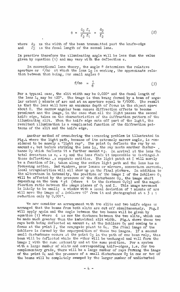
where d2 rs the width of the beam transmLtted past the knife-edge and T2 1s the focal length or' the second lens.
In practice therefore the illuminating angle ml1 be less than the value given by equation (I) and may vary with the deflection E.
In conventional lens theory, aperture or x*/no
the angle R determines the relative at which the lens L2 is working, the appronmate rela-
tion between them being, liar small angles 0
f/no = 1 I3 (3)
For a typical case, the slit width may be 0,020" and the focal length of the lens L, may be 120". The image is then bein formed by a beam of angu- lar extent & minute of arc and at an aperture equal to f/6000. The result is that the lens wrllhave an enormous depth of focus in the cbJect spare about 0. The narrow angular beam causes diffraction er'fects to become prominent and the image, in the case when all the light passes the second knifo edge, takes on the characteristics of the diffraction pattern of the illuminating slit. when the knife edge cuts off part of tho light, the resultant illumination is a nompllcated function of the diffraction pat- terns of the slit and the knife edge.
Another method of considering the rocu ssing problem is illustrated in Fig.4 where the light path, because of its extremely narrow angle, is ran- sidered to be merely a "light ray". The point 0, deflects the ray by an amounts, but before striking the lens L2, the ray meets another dlstw- , bance 02 which deflects it a further amount s2' on arrival at the lens the total deviation is E, + ~2 and the lens finds it impossible to dlstingui-h these deflections -s separate entities. The light patch at I will merely be a function of CE, taken along the entire light path and the lens has no focussuq action. Bad vrLndovrs , poor lenses or mirrors, convectron currentsz local irregularities will all shovr up in the final picture, In addition to the alteration in intensity, the position or' the image I of the Sohliere 0, will be affected by the presence of the disixwbance 02, the image shift depending on the term s2t (where t is the distance 0,02) and the magni- fication ratio between the xmage planes of 0, and I. is likely to be small;
Thxs image movement a window with a local deviation of 1 minute of arc
will move the image of rl Schllere IO” irom it and photographed at a 3 : I reduction only by 0.001".
We now consider an arrangement virlth two slits and tie knife edges so arranged that the beams from both slits are out off simult~e~sly, Fig.2 will apply sgain and the angle between the two beams ~~11 be given by equation (1) where d IS now the distance between the two slits which can be made much greatcr than the individual slit width. Fig.4 show: these tire rays both being deflected an amount e, at the Schliere 01 and coming to a focus at the point I, the con~ugato point to 0,. The r'inal image of the Schliere is forme by the superposition of these two images. If a second small drsturbance occurs at the point 02 in the path of one beam only, this beam will be deflcctcd while the nther will be unchanged and ~nll form the image I with the same Lntensity and at tie same position. For a system with a large numbLr of slits and corresponding knife-edges, i.e. for two complementary grids, there will be a large number of rays for%mng the image of the point 01 and the pr~sencc of a small disturbance 02 in one or tw of the beams will be complotcly swamped by the larger number of undisturbed
-4-

bomll::, 'Ihe syntcm now has a focussing action and the image from eve~.y slit wll only coincide exactly III position and br-ightness for dlstur- bances on the on+ plane 01, conjugate to the xmagc plane.
An altcrnatlw point of view uses the concept or' the f/no. C'ith the same lcnb ~14 previously consldercd, the single slit width of 0.020" may bu rcplncod by B 12" grid containing 100 or more slits.
The anf>le 0 subtonGed by the outer 'xams at the projection lens L2 1s now ‘about GO, ccplvalsnt to f/IO and at this relative aperture the depth of focus ~%ll be much reduced; small disturbances nearer 01‘ far- ther Imm the lens notbcing recorded. 'This 1s not exactly equivalent tc the usu,J c~iso of lens focussing as thoru 1s not necessarily any phase relationshLp between the v.~r~ous b:ams ,rn+ they k?ll therefore not intcr- i'erc to I'orm a diff7x.ction image in a11 cases.
3 Opkcal Limitations of the focussing System
ThL cxpl,xnntions ylvzn of the few ssing actlon also help to bring out some of the lzmitlng r'~lotors in this type or' optrcnl imagery.
Au thi: final image is m,tde up from ovarlapprng images formed by dzf- l'erent light rays, it 2s essential that these rays should all have the sine deviation, but unless two-dimcnslonal Schliere arc being observed, so that oth~rvu~.sc the rays arc in a unlI'orm medium, th1.s is not 10.cly to happen, Each my will pass through a diil'rerent plrt oi‘ the three dlmtin- SLOM~ P1cld. there will be small d~.lYertnccs In the deviation ol' each r?y nrd the images lormcd on the screen ~111 h.Lve ciliferent brightncssos end positions. 'The i'inal pioture will. not have the correct intensity :md rril.1 bc s1lghtl.y blwrod 11' these dU'f‘eronccs in dsvlation arc w1al1, Ails i'cr :;chlicre ol small diamei,er A mbltigle UIEI~C may be formod. This ei'x'ect :- rathcy sinnlnr to th? er'r'cct oi optical ~bcrratlons upon the rim1 ~mag:i: qu.,llity 01' a photograph.
A Luther difl'Loulty nriscs ~?rom the fact Ihat the: beams stnklng tlx Schliurc, do not 40 50 311 at the sCunc angle, and vnll therefore bc Ilevi- atcd by uncqunl amounts. Since the angle subtunded by the bwm 1s small, this diifertinoCY is unlikely to be lurgo unless the mean angle bctweon thC bcm and the dcns:lty podrent is large. This er'iect ~lwayr, exists horvevtr
and must lend to an unccrtnin relationship between the density gsadicnt and the lntonolty in the Schlieren image*
The use 01' the term 'idepth 01' focus" suggests that, outside a certain range, dzvinting ob3Lct.s will not show in th6 final picture. This is only partly tn~e,,dqcn∈: Inr~~ely upon thL L:lze of the disturbance. For a very small c?Lsturbnncc, ~~11 outside focuc, only one beam may be affected in? the loss to the film1 Lmaec mly be small. But 13 the ciisturbnnce affects a large proportion of the total beams, it will be wry noiww&i~ in the final pictwe ?:4 .in intensity difference and a very small shift in posl tion. Should 3.~ disturbance cover completely the required Schlierc then the dovinticns will bb additive, the positlon or' the lmsge on the screen will be nltercd and the intensity of the image will correspond to the comblnod dLvi,ltion %lnd will, therefore, not be a true in&cation of the deviation or‘ thz Zchlicre in focus.
?Jhile it 1s i,l-uC lh.ut the effec, of sn out of focus disturbance on the focvssed Schlierc IS mlsch leduuccd, the opposite 1s also true and an out of I'OCM disturbance x'fects the imge over a much larger area. In pig.5 a iuisturbanoc 02, r.ot in focus, would In a single slit system merely nyfcct ,m UC:I ,LB tiqml to Its mm area in the plane oi' focus. Using 3 multi-slit system >Jith ~u1 illuminating ccne 01' angle 0 an increased area p.1~1 <<ill be ,u‘fti,ct,cd by titi disturbance even though the influence of the
-5-
distmbance will be mch reduced in the original area AB. The er‘fect of the out of l'ocus disturbance is spread out and weakened.
The I'ocussing er'lect is in many ways very smilar to that seen in normal pictorial photography where objects not in focus still appear in the iin&i picture vnless they are very small. They appear to be larger than when in focus, are very diffuse and when subtending a ma.11 angle at the camera, allow other obJects to be seen through them. This is the appearance of out 011 I'oms disturbances ir? a Schlieren fz$d and iI' these disturbances are large m zrea or possess large deflections they will always be apparent in the final picture alt'lough In a diffuse manner. In the Schlieren oaso moreover there may be an rncrease in rlluminat-Lon and a slight change of the posrtion of a Schlicr 2 In the plane qf focus, due to an out oC focus rljsturbance.
In spite of these dif'liculties, In a great many cases mfomation 2bou.t a three-dimensional system oan be obtamed by takrng a series cf photographs through l'ocus. The posltion of any Schliere can then be est-L- mated by fmding the plane of sharpest magery. When sharp dlscontmuities are present, this cm be done w-th an accuracy comparable to that or' focus- sing In normal photography. In general, however, a change of focus ml1 merely alter the LntLnsiiy dlstrlbutlon rn the image, there ~111 be nothing defmite to fccus upon and the new intensity dlstrlbution will not be a reliable gulda to the actual density gradients x.n the plane of focus.
4 Der'ects In Optical Components --
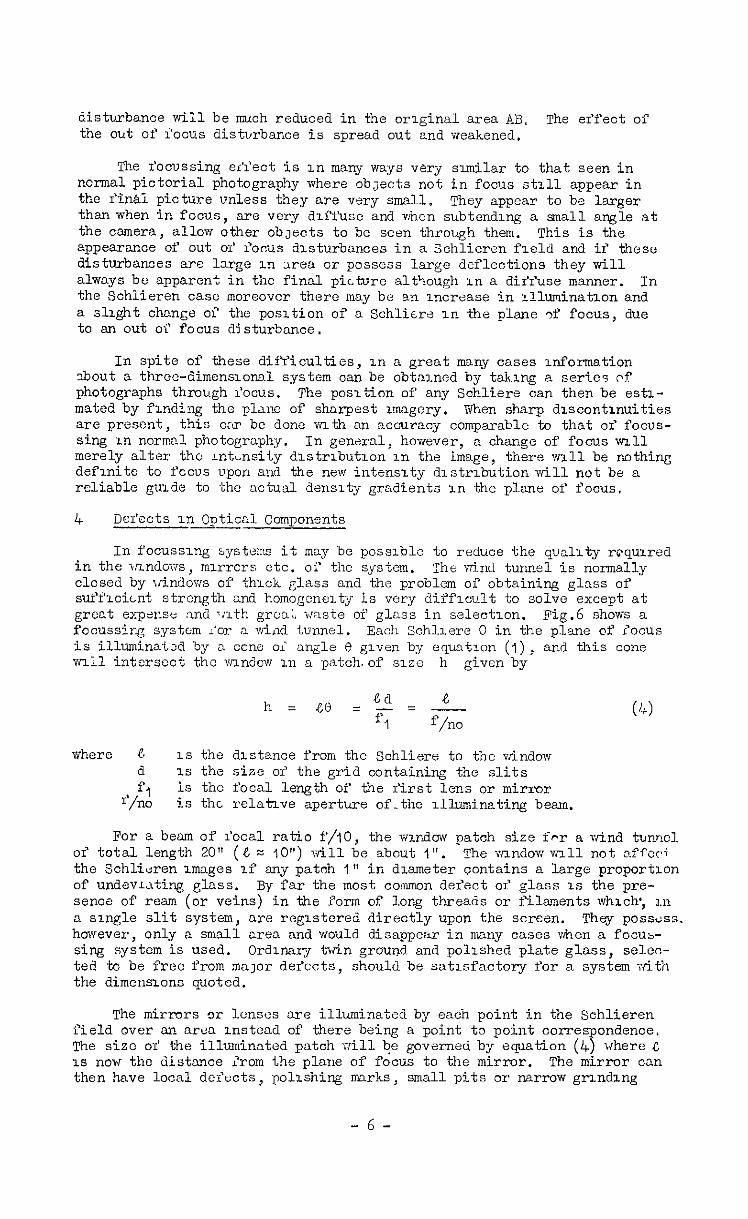
In i'ocussmg systems it may be possible to reduce the quality roqumed in the mndovs, mmcrs etc. oi' the system. The wind tunnel is normally closed by window of tkck glass and the problem of obtaining glass of sufflcimt strength and homogeneity is very diffloult to solve except at groat expense and T!lth gmxti, rmste of glass in seleotlon. Fig.6 shows a focussing system l'or n w-i,~d tunnel. Each Schllere 0 in the plane of locus is illuminated by a cone oi angle 8 grven by eqmtlon (I), and this cone ml1 intersect the endow ~1 a patch.of size h given by
h= ~0 z'~=-%.- F- 1 f/no
where P. 1s the dlstance from the Sohliere to the window d 1s the size or' the grid containing the slits
f 1 f/no
is tho focal length of the I‘irst lens or mirror is the. relative aperture of-the -Lllminating beam.
For a beam of focal ratio f/IO, the wmdow patch size i*r a wind tunwl of total length 20" (e = IO") will be about 1". The vrmdovrvnll not aff+cc+ the Schlitiren mages 1.f any patch 1" in dmmeter contains a large proportion of undevk~ting glass. By far the most comnon defect 01' glass 1s the pre- sence of ream (or veins) in the form of long threads or filaments which; m a smgle slit system, are registered directly upon the screen. They possess. however, only a small area and would disappear in many cases when a focus- sing system is used. Ordmary twin graulrd and pollshed plate glass, seleo- ted to be free from mayor der'ccts, should be satxfactory for a system -&IA the dimensions quoted.
The mirrors or lenses are illuminated by each point in the Schlieren field over an aron mstead of there being a point to point correspondence. The size oi the illuminated patch will be governeti by equation (4) where C IS now the distance irom the plane of focus to the mirror. The mirror can then have local defects, polmhing marks, small pits 01‘ narrow grmdmg
-6-

zones without arr'ectzng the image, provldlng these never cover a high pro- portion 03' this illumrnated ~63.
5 l~ocu:,simg System No .I
This, rhe mo;t ample system, consists of a single lens and 1s shown In Fig.7. Rere L IS thy lens, AB the r;rld, CD the foovsslng'plane con- tanning the Schllure, ?F the plane of the complement&j or knife-edge grid upon which 1116 lens i'ormo 2n mage ol the prmary grid. The plane GII, conpgatc to the :;chlierc plane CD, contains the screen or photographic. film upon vmlch tile xmage is recorded.
h = g NL-cl +-- L, L
, r-t i-2
In this system, then, a sizoablc ~Y.eld d'&i can be obtained with a t Lj
lens oi zero appcrture I). Using the full Yield given by equation (5) the extrme pmnts cufi'er from conulderiible vlgnettwxg and the focussing ai't'cct is aocordlngly much reduced. The largest i'ield that can be used wIthout vlgnzttlng 1s given by
L' the Schliere 1s nearer the grid cand a large grid 1s used or by
h = D(L-4) &_ci II L
0' the Schlicre is near the lens and a large lens is used. The effect of vi@xttLng LS to snake the light lnionsity loss Ln the outer parts or? the Yield. As this upsets completely the relationship, between light intense@ and deflection, and may lead to the masking of' Sohliere in the outer parts of the fzeld, vignetting is a bad f:ullt; In thew systems. It should be lnvestlgated in thti undisturbed ?ield and only thb centralunvignetted area used 111 subsequent work.
The total Illumikting cone is given 2or.small angles by the smaller value or' the i.xo expressions
These are for oorre‘sponckng conditions to those oY'equations (6a) and (Gb) above.
(8)
-7-

The sisc of the image on the screen is
This image SYZ.~ can always be made more convenient by the use of an auxxliary lens between the complementary grid and the screen.
The necessary focussing conditions are
In this equation all the terms are regarded as positive in Fig.7.
The image movement As' at the knife-edge for a deviation E at the plane 0, is given by
The total deviation to bring the image from zero to maximum intensity IS given by
(12)
where s is the width of the individual slits in the primary grid.
The black spaces in the primary grid should be large enough to pre- vent mterferenoe bekeen the individual beams at large deflections. Tho thickness of the black spaoes is given by
t = E(L-8) (13)
vherc E is the maximum deflection possible in the Schlieren system.
Equations (5) to (13) suff'roe to design or~to calculate the perfor- manoe of this type of system. AS an example WC take a system vnth a 3 : 1
reduction of the grid and a rendering or' the Schlieren field at 1 : 1 mag- nificatlon. From an application of equations (8), (9) and (10) the dimun- sions become L = 4F, 4 = 7.F and if the illuminating cone 1s to work at F/10, D = ~/IO or = F/j. The lens should have a mrnimum aperture of f/5 ‘ Ii the system is to work with a 20" wind tunnel, the Sohliere being approtimately central, then L must be above 20" i.e. 4F = 20" or F = 5" and D = 1". The system can use a 5” f/5 lens.
For practical reasons, the largest grid would appear to be about 12" square 1.e. d = 12". Application of equations (3) and (6) gives
,,=~+l+&$~ iI vignetting is permitted 4
OX- h = 6” - $1 = 53” if no vignetting is permitted.
The complementary grid at 3 : 1 reduction ~1.11 be 4” square and at this size the vidth or' the line obtainable with sufficient definition 1s about 0.003" equivalent to 0.009" slit width in the primary grid. V/i th
-8-

this slit width and the grid-Schlieren separation of IO", the total devl-
ation from zero to maximum Intensity will be 0.009 - = 3 minutes of arc. IO
Wrth the system set to mean lntenslty 3 range of 2 I& minutes of deviation oan be measured.
Thx calculated system is relatively lnsensitlve, at mean setlang a lq change ~nbrightness bang given by a 9 set deviation. The field cover is high for the &meter of the lens, an unvlgnetted field of 53” being given with 3 lens or" only I" diameter. It has therefore been called a. wide-field system. To aohiwe this wxle field, however, requires the use of large grids with line slits and th dse are not easy to make and set up.
The lens requlranant should be easily met, the system calculated re- quming n 5” lens at f/5 covering a flcld angle of 30° total. The main disadvantage uf the method 1s that the principle rays are inclined at an angle to the axis of the wind tunnel, 2nd that therefore, unless the Schliere arc approximately two-dimensional, the intensities recorded upon the sowon will not be truly reprcsatative of the density gradients of the Schllcre In fcaus.
G Focussing System No.2
The previous system reguwes n l~rgs diameter grid unlike the usual system whioh requires large dxuneter lenses. A modification to the first system nukLS USC or' a large grid prcduced optically. The nrrzngement is shown In Pig.8 in whhlch an image of the r&l grid S is formed by a lens nt n position S' ,
I,, A condenang or field lwx L2 must bc used to form an
image of the lens Lq upon kho third proJrjction lens L3 to ensure an adoquntc illuminatlne; bean. The r'unotion of this thwd lens 1s ssmil:tr to that of the lens in tho first fooussing system, namely to produce an image pf tho grid S' upon n oomplemcntnry grid S" and an Image of the Schliere 0 upon a screen nt I. Tho equations of the prcv'iou=: section govern the performance: of this part of the system. A completely symmetrical arrangement oan be wed vslth a supplumontnry lens, If required, bebvveen the complementary grid and the soroen.
This system may be more simple in USC), as it vi.11 be easier to make n large field lens L2 than a large grid, particularly as the lens need not have great aowuraoy of fxgwrc. The main disadvantage of this system 1s its lenp% for it w~llbc at,least twice 3s long as the previous system, and if the lens L2 1s to hwo n reasonable r'ocal length may be more than twice as long. It also suffers i'romthe some difficulty as the previous system lr‘ the Schliere arc not ,111 in one plnnz:, for the prlncrpnl rays are inclined to the axis.
7 Fooussinfi SyystemNo.3
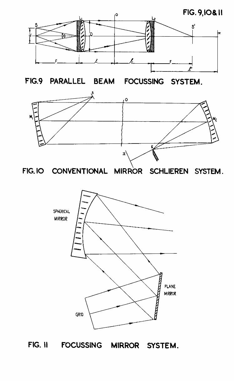
This is the counterpart of tho oormnon parallel beam Schlieren system, with grids replacing the slit ;md knife-edge. The system 1s shown in Fig.9, in which the grid S is plaoed at the focus of the lens L2, so that a paral- lelbeam pngszs through the wind At the foous of thxs lens,
tunnel to the projeotron lens L2. an image of the primary grid is formed upon the complc-
mentary'grid S'. An image of the Schliere 0 is formed upon the screen at I. >
The introduction ol? a ikxitc grid of size cl, iliuminates the Sohliero Mnth a cone of angle 0 glvan, for small values of 8, by '
e= .t = 1 F f/no
(13)
-9-

where F 1s the focal length 02 the two lenses ~/no 1s the relative aperture at which the illuminating beam works.
The diagram shows that Schllere 1~1 the plane 0 will not all be ~llu- mnated by this ;ull cone of light, that vignetting will occur and that the total dlsmeter of the field without vignetting will be grven by
h = D-CO = j,-%i E
(IL;)
where & is the dlstanoe of the Schliere frcm either lens if placed cen- trally or is the longer of the distanozs L,O JQO if unevenly spaced. The * field is therefore restricted compared vnth the usual single sht system m which a field equal. to the lens diameter D is obtained. The size of the Sohlicren.fxeld upon the screen I 1s given by
and t,’ sd c arc connected by the equation
L= 1+1 F &' J?
with both distances being regarded as positive in the diagram.
(16)
The change =n ray position As' at the oomplementary grid for a devi- atlon E 1s given by
AS' = EF (17)
and so is indcp~ndent of the separation of the two lenses ana the gchllere position. The miuclmum measurable deflection from zero to maximum inten- sity is then given by
where s is the wdth of the individual slits 1.n the gricl.
These equations (13) to (I?) allow the complete system to be designed or the performance of a given system tc be calculated.
As a numerical example we vail assume tw 36" f/6 lenses are used for the lenses L, and L2. For an illuminating cone work1 at f/j0 the grid size frcm equation (13) is d = 3.6". From equation T 16), in order to have a real image of the Schkere 0 formed upon a screen, C would nc~l to be larger than F i.e. 36" becomes the least value for G. Under such cumunstanoes i-le find
h = 3 - 36 = 5.7" - 3.6" = 2.1".
6.3 10
The field without vignettxng is much reduced and would be reduned to zero if with this arrangement the lenses had been separated by 144" to produce a I : 1 image of the Schliere upon the screen at I. However the use of an auxiliary lens placed beyond the knife-edge allows the twa lenses to be brought oloser together, and we therefore take the case of Flg.9 dth . the lenses separated by 20" and an auxiliary-lens-plaoed at L3 to focus the . Schlleren usage.
- 10 -
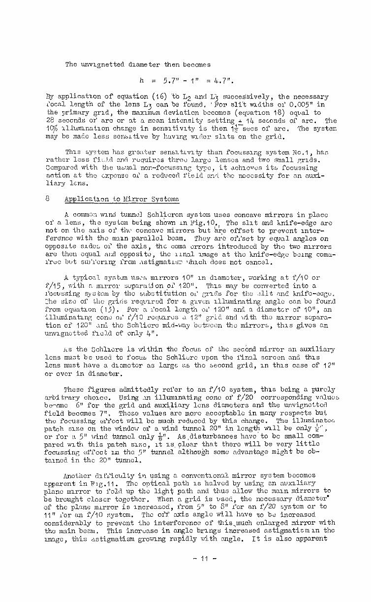
The unvlgnetted drameter then becomes
h = 5.7" - 1" = 4.7".
By application of equation (16) %b L2 and Lj succeSsively, the necessary r'ocal length of the lens L3 can be found. 'mm sli't wLdths 01' 0.005" in the primary grGl, the max-~.mum deviation becomes (equation 18) eqL*al to 28 seconds 01' arc or nt n mean intensity setting A 14 seconds of arc. The 19 lllwnlnatlon change in sensltivxty is then I&-sacs of arc. The system may be made less sensLtive by hrrving w(ler slits on the grid.
This system has gro:iter senslkvlty than focussxng system No.?, has rather less I'iLld zr~nr? ruquiros three large lenses and two small ~1~3s. Compared with the usual non-focussing typo, it achlews its focussing action at the cxpcnsc cl n reduced field snrl the necessity for nn xzi- liary ltns.
8 Applicatlgn to Mirror Systems
A commm wind tunntil Schlicren system uses concave mirrors in plscc of a lens, the not on the axis
sysiem being shbwn LII Fig.lO., The slit and hnife-edge arc or' tlu% ccnc~~c mirrors but 'are offset to prevent Inter-
ference with the rnxx~ parallel beam. They arc oll'set by equal angles on opposite sldc; cl the axis, the ccma errors i~trodwcd by the two mirrors are then cq~al nCi opposite, the lLna1 Image at the knife-edge bG,rng ccma- 1'ruc but sul'l'erlnf: l'rcm ,\stigmatls, Tghihzch does not cancel.
A typical system us?:, mxrrcrs IO" 1n dlsmcter, working at f/IO or f/15, vrith n :~IL‘TOY ;;up:*r:~ti on ,oi 120". This may be converted into CI I'ooussing s~stcm by i&c subC:tituti.cn oi gr1.d~ for the .jlit :ind knife-oag<:. The siec of the grids req~xrcd. for a g~.von xllwninsting snglc can bo found from equatron (lj), E'CY 3 loc:rl length 01' 120" and 3 diameter of IO", an illuminatln~: cone 01' f/IO rcquzws &I 1%" grid ahd with tho mxrror scpnra- tion of 120" xd the Sch'Licrc mid-way butwccn the mirrors, this gives an unv1gnottea f1old of only 4".
iis the Schlwre is within the focus of the secbnd mirror an auxiliary lens must be used to focu:. the Schlierc upon the I'iml sorcen z& this lens must have a dlzrncter as lxrg~ a6 the second grid, in th1.s case of 12" or over in diameter.
These figures admittedly refer to an f/IO system, this being EI purclg s.rbitrRry choxc. Using 223 illwmm.ting cone of f/20 corrcspcnding vnlucs be-cme 6" for the grid and .wxi+.ry lens dizmoters and the unvigne:.tcd field becomes 7". Thcsc vnlues are more ncceptable in many respects but the focussing ullcct will bc mua+ reduced by thi.s change. The illuminntca patch size on the w-indo~~ of ZI v&nd tunnel 20" in length 1~11 be only $-", or for R 5" vhl tunnel only 4". As,disturbanoes have to be small com- pared 1~1th this patch s~o, lt IS, ~lcnr that there will be very little focussing ef'l'eot I.J~ the tj" tunnel althoukh some &vantage might be ob- tanned in the 20" tunnel.
Another dlEZiculiy in using 3 conventlonll mirror system becomes apparent in F1g.11. The cpkioal path 1s halved by using: nn rxuxlliary plant m~rcr to i'old up the light path and thus allow the mxn mirrors to be brought closer togother. When a grid is ~gsed, the nocess~ry dismcter' of the plane mLrror is lncre3sod, from 5" to 8" <or sn f/20 system or to 11" ior an f/IO system. The off axis angle will hctvc to bti increased considerably to prevent i.hc interference of this,much enlarged mirror with the m&n beam. This incrvxe in Culglc brings increased nstigmmatism UI the mgc, this ristigmstism grc~ang rapidly with Enngle. It is also apparent
- 11 -
, that all the slits do not subtend the ssme angle with the axis and for .those at one edge of the grid XI ektra 3O angle 1s necessary for an f/IO system. The increwed :Istigmatism present in some of the slit Images ~a11 e?Yectively reduce the f'ocusslng action of the. system and cause 3 general loss of definition, this being accentuated by the loss due to the lnorease of the overall angle vulth the axis and consequent astxgmatism.
The sensitivity of the mirror system should not be affected by the substitution of the grid prbvldlng the slit dimensions have been correctly chosen. It seems unhkoly, however: that the full benefit of a focussly system can be obtslncd with the usual concave mirrors owxng to the large f/no's ancl because of the necessity of forming images of good quality at large angles off--3~1~. IIirrors are known to be poorly corrected for ofi- axis aberrations and, from this point of vi+w, the use of well corrected flat-field lenses of much shorter focal length seems to be necessary if the full advantage of the focussing system is to be obtained.
9 Practical Details
It is not easy to suggest the best values for all the variables of these systems, and It may well be that the Schlieren user will require a number of systems having different sensitivltles and field dlmeters, these being the m?in variables. For fields of 4-5 inches diameter with a 1% sensitivity of 2-3 sew deviation, f/6.3 1
the system of section 7 using 36" enses should give good results. Shorter focal lengths could be
used with a loss ol" field nrd sensitlvlty.
The two main lenses could be photographic lenses or even doublet lenses could be used as they have to handle a total angular field of 60. They &ould be well corrected for spherical aberration, coma and
only
chromatic aberration if the ilknination in the Schlieren f&W. is to be uniform? freu from colour, and the full focussing effect 1s to bc obto.lncd. The auxxliary lens r+quwed cannot be the usual single lens as the imagc- forrmng light 1s no longer confined to a single ray but has 6: cone working at around f/IO In the ObJect space and according to the final image SILZ~: may work at oven smaller aperture ratios in the image space. The spheri- cal aberration present In a single lens may then be sufficient to destroy the definition in the Schlieren xmagc. For an image sxze of 4" in the 36” system, the auxiliary lens has an apertur e of &', a focal length of 18"
and has to cover an image 5" In diameter. A flat field photographlc lens is neoessxy here.
The primary and complementary grids are required to match each other wxth great accuracy, and the optical system should form an image of the primary grid vsrth the highest possible defimtioo. The complementary grid may well be ma& by photography through the system using a photographic plnte in the position at vihioh the primary grid is focussed. The photo- graphic plate, after processing, becomes the complementary grid and has to be replaced In the s31ne position, Auxilxwy marks shduld be placed on the edges of the primary grid, so that the plate after processing can be re- placed and re-aligned wxth the optical ~mago of the primary grid. This method of m&ln(i the complomcntar~ grid has the advantage that any distor- tion in the lens svstem will be compcnsatcd and even though the slit image may be curved slightly, the complcmentnry grid will still match It. If the complementary grid is made by Lontract printing from the primary grid, this mltching ~~11 not occur in the prescnoe of lens dIstortions and intcn- sity errors will a-150. 9
It should also be noted that It is essential for the ocmplcmentsry grid to be roplaccd in the correct plane with great care. If this is not done, the lmagc of the primary grid will not be In focus on the comple- mentary grid and intensity differences vii11 be blurrtid over. In addition
- 12 -

the scale of the -image will be wrong, it will not be possible to have nil the slits cutting off together, the intensity dw to each slit vr~llbe different, the focussing er'fect will be reduced rind the relat-ronshlp be- twecnintensi7;y and air denzlty gradient ~'?y vary over the field. It will thcrcfore be neccsswy to pay mcrc nttentlon to the Lorrect l'ocussing and nligrm?ont 02 the complementary grid ;;hcn scttlng up the apparatus, than is usual m tho cast of ,? sjnglc knife-edgc.
As the gr5d system requires thrj optical components to grve an image over an extended frcld with a fliute aperture, lenses arc more appropriate than mirrors. They have however apprecLablc chromatic aberration and it may be ncocssary to ~orl: NLth monochromatic light perhaps from a sodium lamp or green mercury lq;ht filtcrcd from a high pressure mwcvry lamp. Unless approximately monochromatLc light 1s used the image for-mod on the complementary grid may 11avc dir'fusu coloured edges and the visual Schlicren field will have coloured patches.
lllunnnation of the pr-~m&ry grid may prcscnt a problcim as the arcn'to be illuminated is Lrgc (up to 12" square) and oath slit in the grid must llluminnte the whole of thu unvignottcd field. ii condensing lens of large diameter can be used lf the source has a large enough arca to illvminatc the cntlre field, a condition not found In the compact source type of hzgh pr‘ssuure mercury lamp. The compact source lamp is so desirable for its nearly monochrornati?, highly intense light output that It vnll largely bc used for focussIng systems w.th in opal glass diffuser close to tha grlti. This method of rlluminating loses a groat deal of light In the opal glass and the Xnal image bmghtncss of thz Schlizre upon the screen may be lowr than the brsghtncss normally met in single slit systems.
10 Conclusions
(1) The focussing effect depends upon the Lncrcased ~lluminnting nnglc obtalncd when ~;r~ds arc substituted for the usual knift-edges.
(2) The effect upon the final irmge plane of an out-of-focus Schliwc depends largely upon the amount of dcvlation caused by the Schlwrc and its area.
(3) ~rces T,ath large deviations Yr~ll always b e recorded ITI the fin,11 image even though much out of focus.
(4) The 1oLdtion oi discontin~~t~es czn be fottnd from thew plsno of best roctis.
(5) The lntcnsity distribution ln the plane in focus 1s not a reli- able guide to the rknszty gradients in that plane.
(6) Focussing systems have by normal .nnd tunnel standarCs a ~malll workmg field.
(7) For parallel beam systems the unvlgnetted flcld is considerably less than the mwror or lens diameter although the grids can be small in size.
(8) Z'or Inclined buam systems the field can be larger than the lens dimetcr althcu& ~cry lwgc grid, 0 may be required and these are difficult to m2kc and llluminatc.
dimen;;9-;y;;rd beam syst@-m = s art? at a disadvantage with three- I 'I

(10) iviirror systems are not as well suited as lens systems because of the large or"f-axis aberrations likely to be introduced. Present wind tunnel mirrors cannot effectlv<ly be adapted to t’ocussing systems.
(11) These focussi~z systems requze very great care in setting up and aa;ust!nent.
(12) There are Ilkely to be core sources of xntensity errors xn a focussing system and quantltntlvc work is not likely to be accurate.
(13) The focussing systems are not suitable for general wrnd tunnel work beceuse of their small fields but may be of use as special tools for Investigating problems in three dlmenslons.
(14) The use or' lower quality windows and optical components IS possible in focussing systems.
E. AUthO?? Title, etc.
1 Eurton, R.A. A modified Schliercn apparatus for large areas of field. J. Opt. Sot. Am, Vo1.39. November 1949.
2 Kantrcmtz, A., A sh‘arp-focussing Schlieren system. and Trlmpi, R.L. Journal of Aeronautical Sciences, 17 (1950)
2 (May) pp. 311-314.
%2078.CPSY.h’3. Prtnted rn Greo t hta%n.
- 14 -
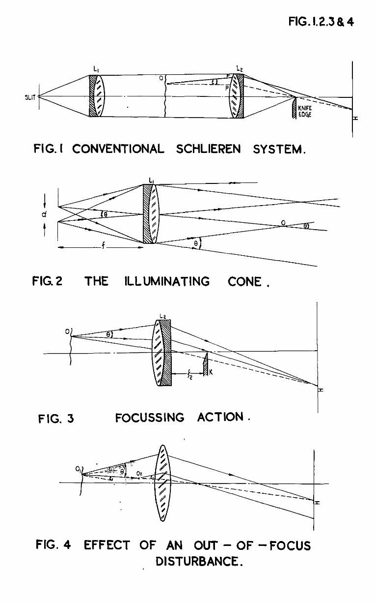
FIG.l.2.3&4
FIG. I CONVENTIONAL SCHLIEREN SYSTEM.
FIG. 2 THE ILLUMINATING CONE ,
I
FIG. 3 FOCUSSING ACTION .
FIG. 4 EFFECT OF AN OUT - OF -FOCUS DISTURBANCE .
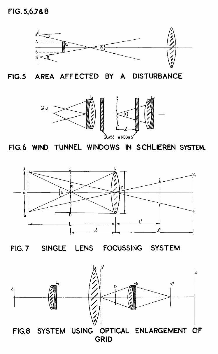
FIG. S,6,7& 8
FIG.5 AREA AFFECTED BY A DISTURBANCE
GLASS WINDOW5 /
FIG.6 WIND TUNNEL WINDOWS IN S CHLIEREN SYSTEM.
FIG. 7 SINGLE LENS FOCUSSING SYSTEM
FIG8 SYSTEM USING OPTICAL ENLARGEMENT OF GRID
L-L.-L-AI ---yTF4 1 FIG.9 PARALLEL BEAM FOCUSSING SYSTEM.
FIG. IO CONVENTIONAL MIRRbR SCHLIEREN SYSTEM.
PLANE
MIRR-OR
FIG. II FOCUSSING MIRROR SYSTEM.


C.P. No. 54 13.065
A.R C. Technical Report
York House, ffigsway, LONDON, w c 2, 429 Oxford Street. LONDON, w I, P.O. Box 569, LONDON, s E 1,
13a castle street, EDMB”RGH, 2 I St Andrew’s Crescent, CARDIFF 39 King street, MANCrnR, 2 1 Tower Lane, wusnx. I
2 Edmund Street, BIRMINOHAM, 3 80 Chzhester Streef, BELFAST, or from any Bookseller
1951 Price 3s. 6d. net
PRINTED IN GREAT BRITAIN
S.O. Code No. ?.3-9006-54