FnIO G-Series GN-9222
24
GN-9222 Specification Revision 1.07 G-Series PROFIBUS N/A Page 1 Date: 2020.07.07 FnIO G-Series GN-9222 GN-9222 (PROFIBUS Network Adapter)
Transcript of FnIO G-Series GN-9222

GN-9222Specification
Revision 1.07G-Series PROFIBUS N/A Page 1
Date: 2020.07.07
FnIO G-Series
GN-9222
GN-9222 (PROFIBUS Network Adapter)
GN-9222Specification
Revision 1.07G-Series PROFIBUS N/A Page 2
Table of ContentsDate: 2020. 4.21 ............................................................................................................................................... 1
Table of Contents .............................................................................................................................................. 2
History .............................................................................................................................................................. 4
1.Environment Specification ............................................................................................................................ 5
2.GN-9222 (PROFIBUS Network Adapter) ..................................................................................................... 6
2.1.GN-9222 Specification ........................................................................................................................... 6
2.2.GN-9222 Wiring Diagram ...................................................................................................................... 8
2.3.GN-9222 LED Indicator ......................................................................................................................... 9
2.3.1.LED Indicator .................................................................................................................................. 9
2.3.2.MOD (Module Status LED) ............................................................................................................. 9
2.3.3.NET (Network Status LED) ............................................................................................................. 9
2.3.4.DIA (Diagnostic Status LED) .......................................................................................................... 9
2.3.5.IOS LED (Expansion Module Status LED) ................................................................................... 10
2.3.6.Field Power, System Power LED (Field Power, System Power Status LED) ................................. 10
2.4.GN-9222 Electrical Interface ................................................................................................................ 11
2.4.1.PROFIBUS Connector ................................................................................................................... 11
2.4.2.Dip Switch .................................................................................................................................... 11
2.4.3.RS232 Port for MODBUS/RTU, Touch Panel or IOGuide ............................................................ 11
2.5.I/O Process Image Map ......................................................................................................................... 12
2.5.1.Example of Input Process Image (Input Register) Map ................................................................. 13
2.5.2.Example of Output Process Image (Output Register) Map ........................................................... 14
3.Parameter ..................................................................................................................................................... 15
3.1.GN-9222 ............................................................................................................................................... 15
4.DPV1 Service .............................................................................................................................................. 15
4.1.MSAC1 Read(PROFIBUS-DP Extensions to EN50170) ...................................................................... 15
4.2.MSAC1 Write(PROFIBUS-DP Extensions to EN50170) ..................................................................... 15
4.3.Error_Decode (PROFIBUS-DP Extensions to EN50170) ..................................................................... 16
4.4.Error Code_1 (PROFIBUS-DP Extensions to EN50170) ...................................................................... 16
5.Diagnostics .................................................................................................................................................. 17
6.MODBUS Interface ..................................................................................................................................... 18
6.1.MODBUS Interface Register/Bit Map .................................................................................................. 18
6.2.Surpported MODBUS Function Codes ................................................................................................. 18
6.2.1.8 (0x08) Diagnostics ...................................................................................................................... 20
6.2.2.Error Response ............................................................................................................................... 21
6.3.MODBUS Special Register Map .......................................................................................................... 21
6.3.1.Adapter Identification Special Resgister (0x1000, 4096) ............................................................... 21

GN-9222Specification
Revision 1.07G-Series PROFIBUS N/A Page 3
6.3.2.Adapter Information Special Register (0x1100, 4352) ................................................................... 22
6.3.3.Expasion Slot Information Special Resister (0x2000, 8192) .......................................................... 22
6.4.MODBUS Reference ............................................................................................................................ 23
GN-9222Specification
Revision 1.07G-Series PROFIBUS N/A Page 4
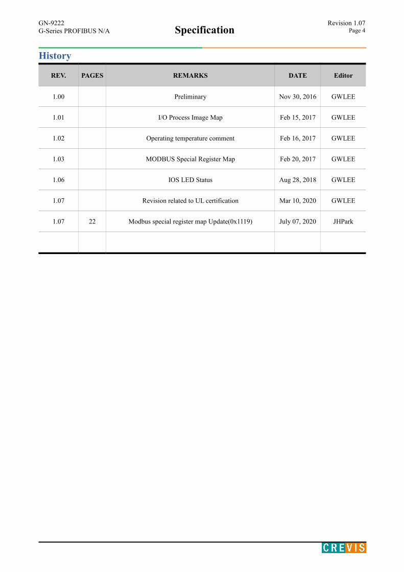
History
REV. PAGES REMARKS DATE Editor
1.00 Preliminary Nov 30, 2016 GWLEE
1.01 I/O Process Image Map Feb 15, 2017 GWLEE
1.02 Operating temperature comment Feb 16, 2017 GWLEE
1.03 MODBUS Special Register Map Feb 20, 2017 GWLEE
1.06 IOS LED Status Aug 28, 2018 GWLEE
1.07 Revision related to UL certification Mar 10, 2020 GWLEE
1.07 22 Modbus special register map Update(0x1119) July 07, 2020 JHPark
GN-9222Specification
Revision 1.07G-Series PROFIBUS N/A Page 5
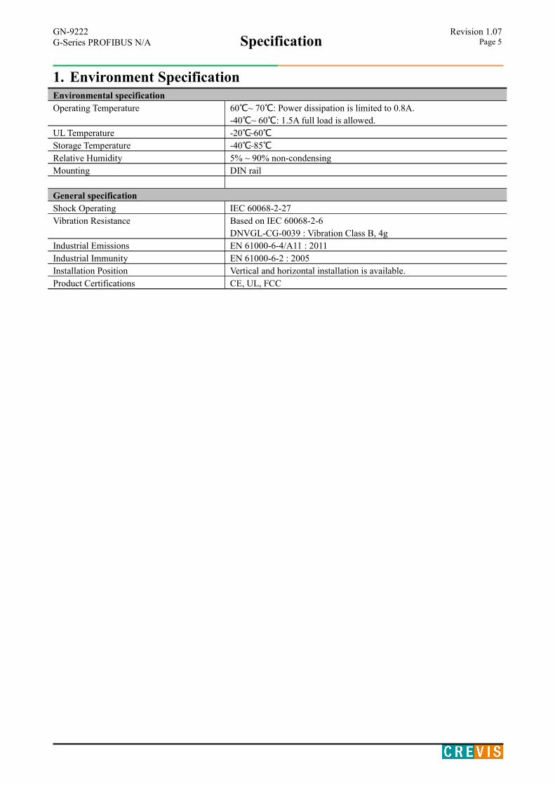
1. Environment SpecificationEnvironmental specificationOperating Temperature 60 ℃~ 70 ℃: Power dissipation is limited to 0.8A.
-40 ℃~ 60 ℃: 1.5A full load is allowed.UL Temperature -20℃~60℃Storage Temperature -40℃~85℃Relative Humidity 5% ~ 90% non-condensingMounting DIN rail
General specification Shock Operating IEC 60068-2-27Vibration Resistance Based on IEC 60068-2-6
DNVGL-CG-0039 : Vibration Class B, 4gIndustrial Emissions EN 61000-6-4/A11 : 2011Industrial Immunity EN 61000-6-2 : 2005Installation Position Vertical and horizontal installation is available.Product Certifications CE, UL, FCC
GN-9222Specification
Revision 1.07G-Series PROFIBUS N/A Page 6
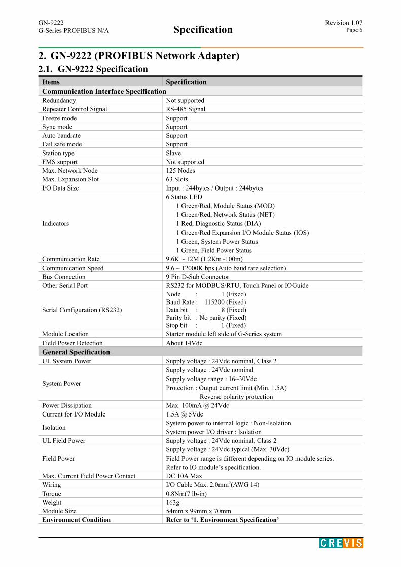
2. GN-9222 (PROFIBUS Network Adapter)2.1. GN-9222 Specification
Items SpecificationCommunication Interface SpecificationRedundancy Not supportedRepeater Control Signal RS-485 SignalFreeze mode SupportSync mode SupportAuto baudrate SupportFail safe mode SupportStation type SlaveFMS support Not supportedMax. Network Node 125 NodesMax. Expansion Slot 63 SlotsI/O Data Size Input : 244bytes / Output : 244bytes
Indicators
6 Status LED 1 Green/Red, Module Status (MOD) 1 Green/Red, Network Status (NET) 1 Red, Diagnostic Status (DIA) 1 Green/Red Expansion I/O Module Status (IOS) 1 Green, System Power Status 1 Green, Field Power Status
Communication Rate 9.6K ~ 12M (1.2Km~100m)Communication Speed 9.6 ~ 12000K bps (Auto baud rate selection)Bus Connection 9 Pin D-Sub ConnectorOther Serial Port RS232 for MODBUS/RTU, Touch Panel or IOGuide
Serial Configuration (RS232)
Node : 1 (Fixed)Baud Rate : 115200 (Fixed)Data bit : 8 (Fixed)Parity bit : No parity (Fixed)Stop bit : 1 (Fixed)
Module Location Starter module left side of G-Series systemField Power Detection About 14Vdc
General Specification UL System Power Supply voltage : 24Vdc nominal, Class 2
System Power
Supply voltage : 24Vdc nominalSupply voltage range : 16~30VdcProtection : Output current limit (Min. 1.5A) Reverse polarity protection
Power Dissipation Max. 100mA @ 24VdcCurrent for I/O Module 1.5A @ 5Vdc
IsolationSystem power to internal logic : Non-IsolationSystem power I/O driver : Isolation
UL Field Power Supply voltage : 24Vdc nominal, Class 2
Field PowerSupply voltage : 24Vdc typical (Max. 30Vdc)Field Power range is different depending on IO module series.Refer to IO module’s specification.
Max. Current Field Power Contact DC 10A MaxWiring I/O Cable Max. 2.0mm2(AWG 14)Torque 0.8Nm(7 lb-in)Weight 163gModule Size 54mm x 99mm x 70mmEnvironment Condition Refer to ‘1. Environment Specification’

GN-9222Specification
Revision 1.07G-Series PROFIBUS N/A Page 7
* Operating temperature
-40 ~ 70 temperature range specification can be guaranteed ℃ under the following conditions.- Current for I/O Modules : 0.8A below.- Otherwise, temperature specification can be guaranteed with -40 ~ 60℃.
GN-9222Specification
Revision 1.07G-Series PROFIBUS N/A Page 8
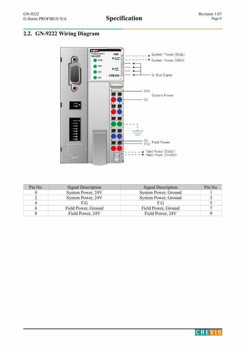
2.2. GN-9222 Wiring Diagram
Pin No. Signal Description Signal Description Pin No.0 System Power, 24V System Power, Ground 12 System Power, 24V System Power, Ground 34 F.G F.G 56 Field Power, Ground Field Power, Ground 78 Field Power, 24V Field Power, 24V 9

GN-9222Specification
Revision 1.07G-Series PROFIBUS N/A Page 9
2.3. GN-9222 LED Indicator2.3.1. LED Indicator
2.3.2. MOD (Module Status LED)Status LED To indicate
Not Powered OFF Power is not supplied to the unit.
Normal, Operational Green The unit is operating in normal condition.
Device in Standby Flashing GreenThe EEPROM parameter is not initialized yet.Serial Number is zero value (0x00000000)
Minor Fault Flashing RedThe unit has occurred recoverable fault in self-testing. - EEPROM checksum fault.
Unrecoverable Fault RedThe unit has occurred unrecoverable fault in self-testing. - Firmware fault
2.3.3. NET (Network Status LED)Status LED To indicate
Not PoweredNot On-line
OFF Device is not on-line or may not be powered
On-line, Not connected
Flashing Green
Device is on-line but has no connections in the established state. - Not allocated to a master
On-line, Connected
Green Device is on-line and allocated to a master
Connection Time-out Flashing Red One or more I/O connections are in the time-out state.
Critical Communication Failure Red Failed communication
2.3.4. DIA (Diagnostic Status LED)Status LED To indicate
Hardware Error Flashing RedDevice has hardware checking error.(with MOD led is red.)
Expansion Module Error Flashing RedDevice has expansion module error.(with IOS led is red.)
IO Configuration Error Flashing Red
Failed to initalize expansion module - Overflow Input/Output size. (244bytes / 244bytes) - Overflow Configuration data size. (244bytes / 244bytes) - Too many expansion module. (Max 63 slot) - Mismatch vendor code between adapter and expension module.
LED No. LED Function / Description LED ColorMOD Module Status Green/RedNET Network Status Green/RedDIA Diagnostic Status RedIOS Expansion Module Status Green/Red
SystemPower
System Power Enable Green
FieldPower
Field Power Enable Green
GN-9222Specification
Revision 1.07G-Series PROFIBUS N/A Page 10
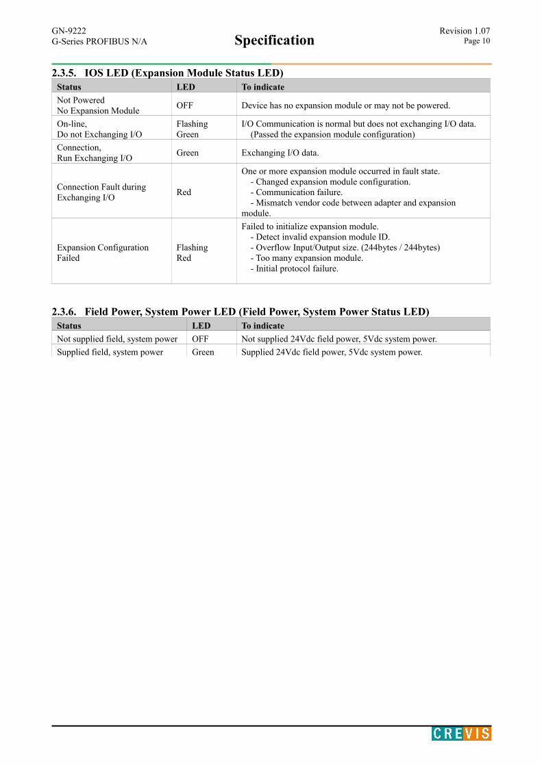
2.3.5. IOS LED (Expansion Module Status LED)Status LED To indicate
Not PoweredNo Expansion Module
OFF Device has no expansion module or may not be powered.
On-line,Do not Exchanging I/O
Flashing Green
I/O Communication is normal but does not exchanging I/O data. (Passed the expansion module configuration)
Connection,Run Exchanging I/O
Green Exchanging I/O data.
Connection Fault duringExchanging I/O
Red
One or more expansion module occurred in fault state. - Changed expansion module configuration. - Communication failure. - Mismatch vendor code between adapter and expansion module.
Expansion ConfigurationFailed
FlashingRed
Failed to initialize expansion module. - Detect invalid expansion module ID. - Overflow Input/Output size. (244bytes / 244bytes) - Too many expansion module. - Initial protocol failure.
2.3.6. Field Power, System Power LED (Field Power, System Power Status LED)Status LED To indicate
Not supplied field, system power OFF Not supplied 24Vdc field power, 5Vdc system power.
Supplied field, system power Green Supplied 24Vdc field power, 5Vdc system power.
GN-9222Specification
Revision 1.07G-Series PROFIBUS N/A Page 11
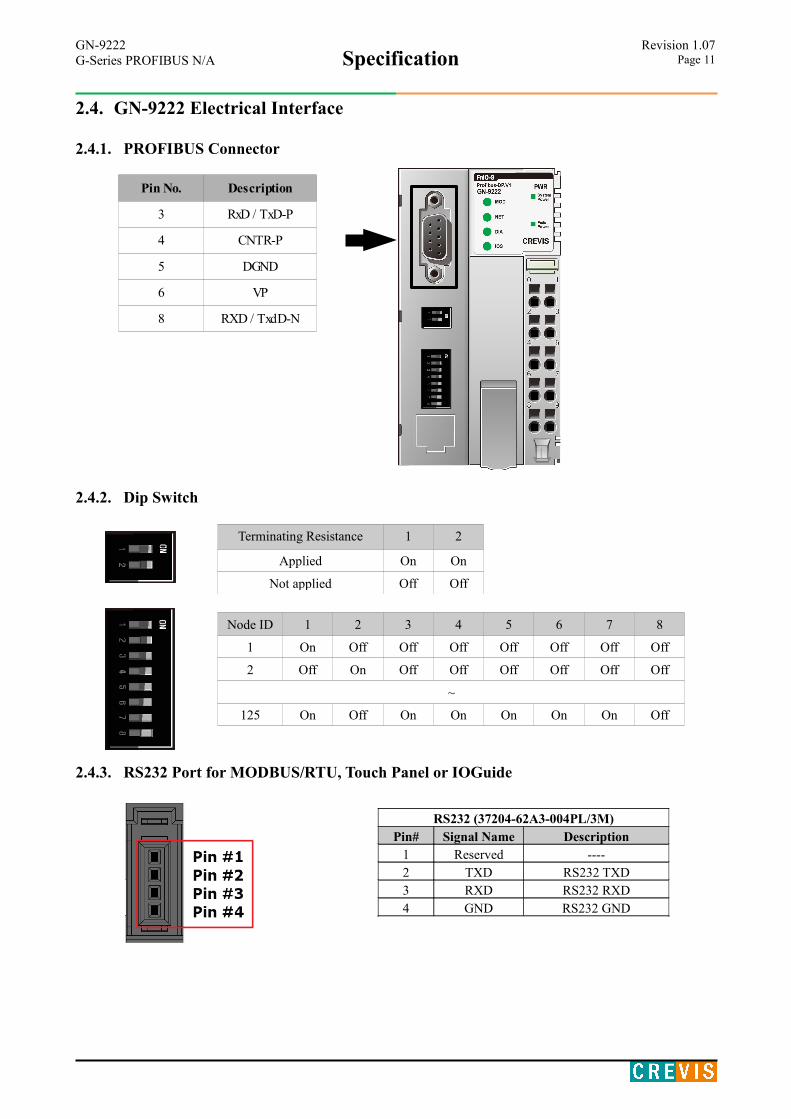
2.4. GN-9222 Electrical Interface
2.4.1. PROFIBUS Connector
2.4.2. Dip Switch
Terminating Resistance 1 2
Applied On On
Not applied Off Off
Node ID 1 2 3 4 5 6 7 8
1 On Off Off Off Off Off Off Off
2 Off On Off Off Off Off Off Off
~
125 On Off On On On On On Off
2.4.3. RS232 Port for MODBUS/RTU, Touch Panel or IOGuide
Pin No. Description
3 RxD / TxD-P
4 CNTR-P
5 DGND
6 VP
8 RXD / TxdD-N
RS232 (37204-62A3-004PL/3M)Pin# Signal Name Description
1 Reserved ----2 TXD RS232 TXD3 RXD RS232 RXD4 GND RS232 GND
GN-9222Specification
Revision 1.07G-Series PROFIBUS N/A Page 12
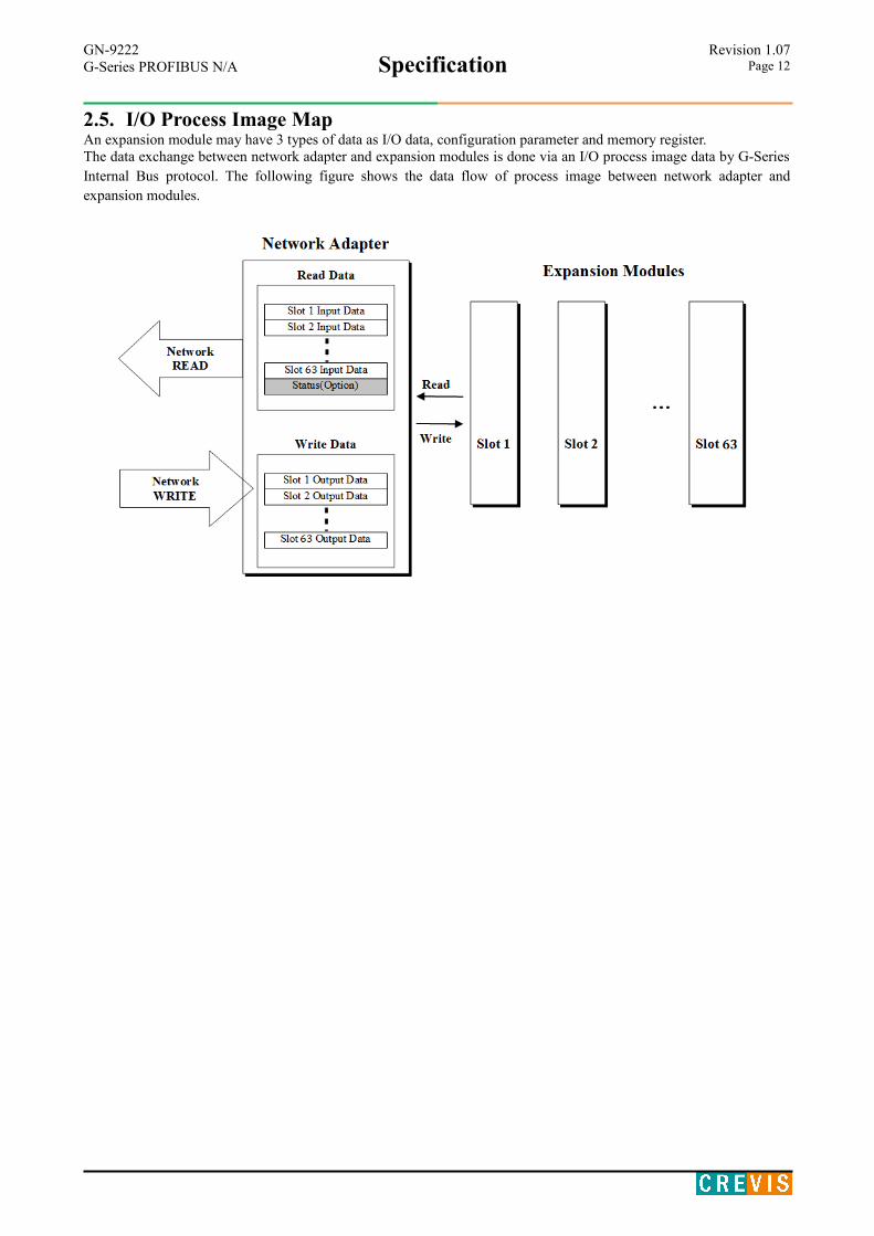
2.5. I/O Process Image MapAn expansion module may have 3 types of data as I/O data, configuration parameter and memory register.The data exchange between network adapter and expansion modules is done via an I/O process image data by G-SeriesInternal Bus protocol. The following figure shows the data flow of process image between network adapter andexpansion modules.
GN-9222Specification
Revision 1.07G-Series PROFIBUS N/A Page 13
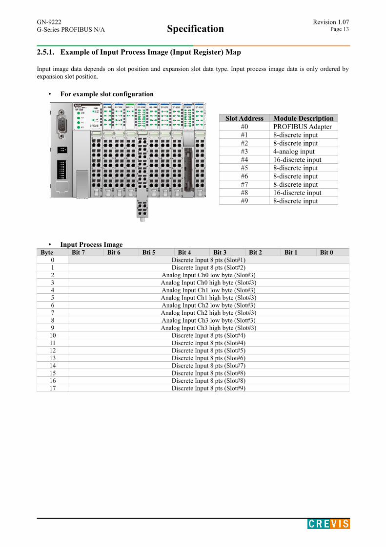
2.5.1. Example of Input Process Image (Input Register) Map
Input image data depends on slot position and expansion slot data type. Input process image data is only ordered byexpansion slot position.
• For example slot configuration
• Input Process Image Byte Bit 7 Bit 6 Bti 5 Bit 4 Bit 3 Bit 2 Bit 1 Bit 0
0 Discrete Input 8 pts (Slot#1)1 Discrete Input 8 pts (Slot#2)2 Analog Input Ch0 low byte (Slot#3)3 Analog Input Ch0 high byte (Slot#3)4 Analog Input Ch1 low byte (Slot#3)5 Analog Input Ch1 high byte (Slot#3)6 Analog Input Ch2 low byte (Slot#3)7 Analog Input Ch2 high byte (Slot#3)8 Analog Input Ch3 low byte (Slot#3)9 Analog Input Ch3 high byte (Slot#3)10 Discrete Input 8 pts (Slot#4)11 Discrete Input 8 pts (Slot#4)12 Discrete Input 8 pts (Slot#5)13 Discrete Input 8 pts (Slot#6)14 Discrete Input 8 pts (Slot#7)15 Discrete Input 8 pts (Slot#8)16 Discrete Input 8 pts (Slot#8)17 Discrete Input 8 pts (Slot#9)
Slot Address Module Description#0 PROFIBUS Adapter#1 8-discrete input#2 8-discrete input#3 4-analog input#4 16-discrete input#5 8-discrete input#6 8-discrete input#7 8-discrete input#8 16-discrete input#9 8-discrete input
GN-9222Specification
Revision 1.07G-Series PROFIBUS N/A Page 14
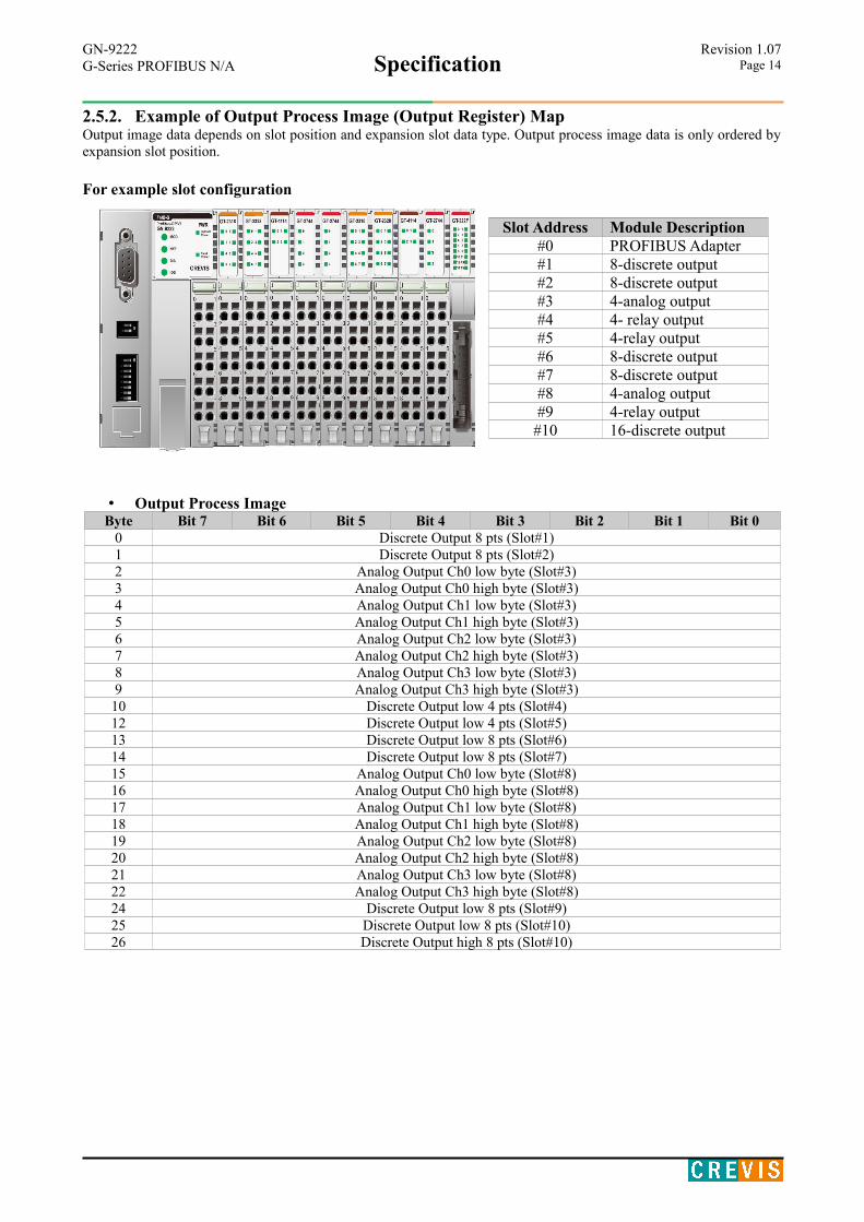
2.5.2. Example of Output Process Image (Output Register) Map Output image data depends on slot position and expansion slot data type. Output process image data is only ordered byexpansion slot position.
For example slot configuration
• Output Process Image Byte Bit 7 Bit 6 Bit 5 Bit 4 Bit 3 Bit 2 Bit 1 Bit 0
0 Discrete Output 8 pts (Slot#1)1 Discrete Output 8 pts (Slot#2)2 Analog Output Ch0 low byte (Slot#3)3 Analog Output Ch0 high byte (Slot#3)4 Analog Output Ch1 low byte (Slot#3)5 Analog Output Ch1 high byte (Slot#3)6 Analog Output Ch2 low byte (Slot#3)7 Analog Output Ch2 high byte (Slot#3)8 Analog Output Ch3 low byte (Slot#3)9 Analog Output Ch3 high byte (Slot#3)10 Discrete Output low 4 pts (Slot#4)12 Discrete Output low 4 pts (Slot#5)13 Discrete Output low 8 pts (Slot#6)14 Discrete Output low 8 pts (Slot#7)15 Analog Output Ch0 low byte (Slot#8)16 Analog Output Ch0 high byte (Slot#8)17 Analog Output Ch1 low byte (Slot#8)18 Analog Output Ch1 high byte (Slot#8)19 Analog Output Ch2 low byte (Slot#8)20 Analog Output Ch2 high byte (Slot#8)21 Analog Output Ch3 low byte (Slot#8)22 Analog Output Ch3 high byte (Slot#8)24 Discrete Output low 8 pts (Slot#9)25 Discrete Output low 8 pts (Slot#10)26 Discrete Output high 8 pts (Slot#10)
Slot Address Module Description#0 PROFIBUS Adapter#1 8-discrete output#2 8-discrete output#3 4-analog output#4 4- relay output#5 4-relay output#6 8-discrete output#7 8-discrete output#8 4-analog output#9 4-relay output#10 16-discrete output
GN-9222Specification
Revision 1.07G-Series PROFIBUS N/A Page 15
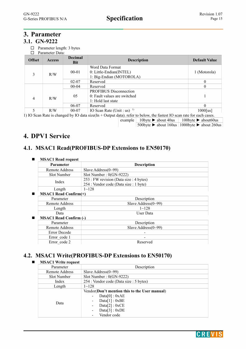
3. Parameter3.1. GN-9222
Parameter length: 3 bytes Parameter Data:
Offset AccessDecimal
BitDescription Default Value
3 R/W00-01
Word Data Format0: Little-Endian(INTEL)1: Big-Endian (MOTOROLA)
1 (Motorola)
02-07 Reserved 0
4 R/W
00-04 Reserved 0
05PROFIBUS Disconnection0: Fault values are switched1: Hold last state
1
06-07 Reserved 05 R/W 00-07 IO Scan Rate (Unit : us) 1) 1000[us]
1) IO Scan Rate is changed by IO data size(In + Output data). refer to below, the fastest IO scan rate for each cases.example 10byte ► about 40us 100byte ► about60us
500byte ► about 160us 1000byte ► about 260us
4. DPV1 Service
4.1. MSAC1 Read(PROFIBUS-DP Extensions to EN50170)
MSAC1 Read requestParameter Description
Remote Address Slave Address(0~99)Slot Number Slot Number : 0(GN-9222)
Index253 : FW revision (Data size : 4 bytes)254 : Vendor code (Data size : 1 byte)
Length 1~128 MSAC1 Read Confirm(+)
Parameter DescriptionRemote Address Slave Address(0~99)
Length 1~128Data User Data
MSAC1 Read Confirm (-)Parameter Description
Remote Address Slave Address(0~99)Error Decode -Error_code 1 -Error_code 2 Reserved
4.2. MSAC1 Write(PROFIBUS-DP Extensions to EN50170) MSAC1 Write request
Parameter DescriptionRemote Address Slave Address(0~99)
Slot Number Slot Number : 0(GN-9222)Index 254 : Vendor code (Data size : 5 bytes)
Length 1~128
Data
Vendor(Don’t mention this to the User manual)- Data[0] : 0xAE- Data[1] : 0xBE- Data[2] : 0xCE- Data[3] : 0xDE- Vendor code
GN-9222Specification
Revision 1.07G-Series PROFIBUS N/A Page 16
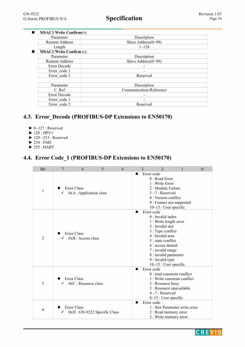
MSAC1 Write Confirm(+)Parameter Description
Remote Address Slave Address(0~99)Length 1~128
MSAC1 Write Confirm (-)Parameter Description
Remote Address Slave Address(0~99)Error Decode -Error_code 1 -Error_code 2 Reserved
Parameter DescriptionC_Ref Communication-Reference
Error Decode -Error_code 1 -Error_code 2 Reserved
4.3. Error_Decode (PROFIBUS-DP Extensions to EN50170)
► 0~127 : Reserved ► 128 : DPV1 ► 129 ~253 : Reserved ► 254 : FMS ► 255 : HART
4.4. Error Code_1 (PROFIBUS-DP Extensions to EN50170)
Bit 7 6 5 4 3 2 1 0
1 Error Class 0xA : Application class
Error code0 : Read Error1 : Write Error2 : Module Failure3 ~7 : Reserved8 : Version conflict9 : Feature not supported10~15 : User specific
2 Error Class 0xB : Access class
Error code0 : Invalid index1 : Write length error2 : Invalid slot3 : Type conflict4 : Invalid area5 : state conflict6 : access denied7 : invalid range8 : invalid parameter9 : invalid type10~15 : User specific
3 Error Class 0xC : Resource class
Error code0 : read constrain conflict1 : Write constrain conflict2 : Resource busy3 : Resource unavailable4 ~7 : Reserved8~15 : User specific
4 Error Class 0xD : GN-9222 Specific Class
Error code1 : Slot Parameter write error2 : Read memory error3 : Write memory error
GN-9222Specification
Revision 1.07G-Series PROFIBUS N/A Page 17
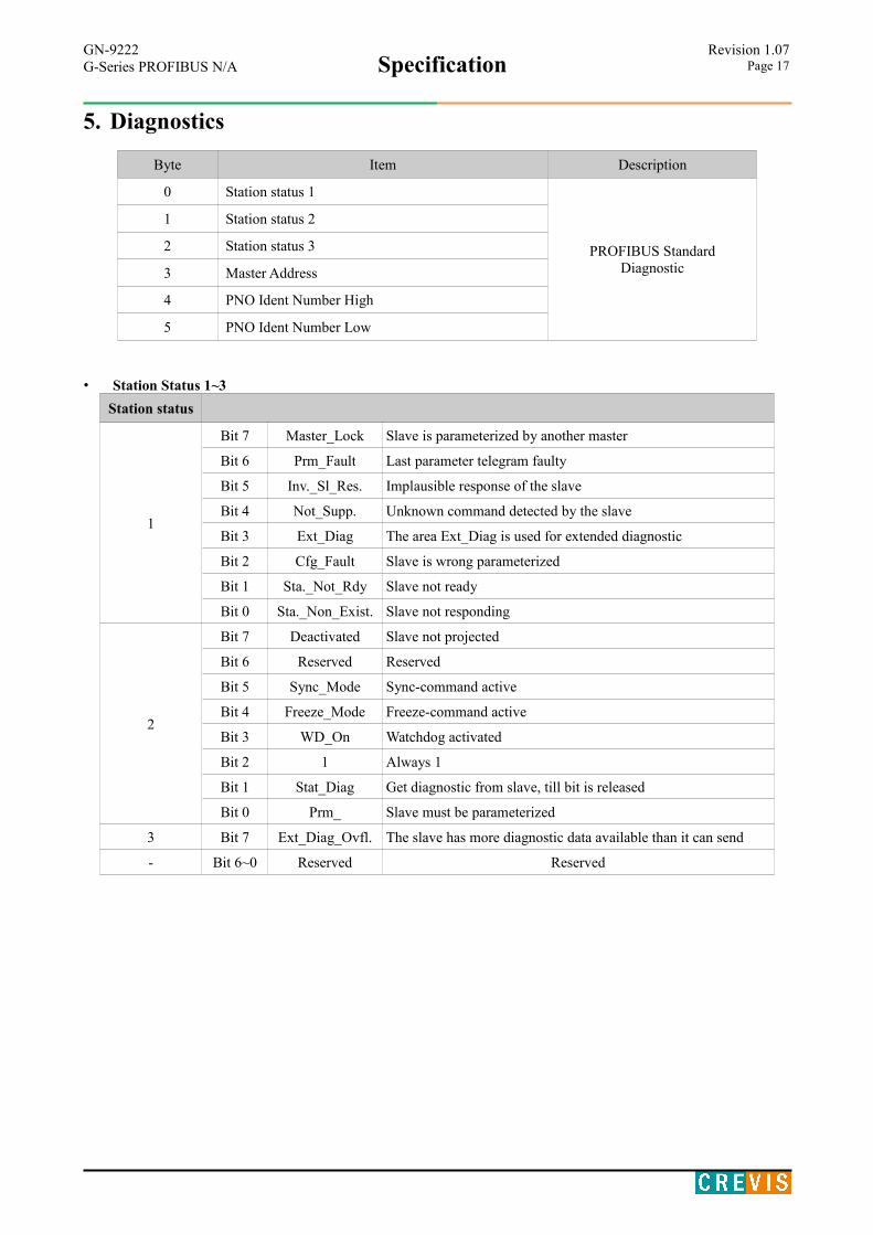
5. Diagnostics
Byte Item Description
0 Station status 1
PROFIBUS StandardDiagnostic
1 Station status 2
2 Station status 3
3 Master Address
4 PNO Ident Number High
5 PNO Ident Number Low
• Station Status 1~3
Station status
1
Bit 7 Master_Lock Slave is parameterized by another master
Bit 6 Prm_Fault Last parameter telegram faulty
Bit 5 Inv._Sl_Res. Implausible response of the slave
Bit 4 Not_Supp. Unknown command detected by the slave
Bit 3 Ext_Diag The area Ext_Diag is used for extended diagnostic
Bit 2 Cfg_Fault Slave is wrong parameterized
Bit 1 Sta._Not_Rdy Slave not ready
Bit 0 Sta._Non_Exist. Slave not responding
2
Bit 7 Deactivated Slave not projected
Bit 6 Reserved Reserved
Bit 5 Sync_Mode Sync-command active
Bit 4 Freeze_Mode Freeze-command active
Bit 3 WD_On Watchdog activated
Bit 2 1 Always 1
Bit 1 Stat_Diag Get diagnostic from slave, till bit is released
Bit 0 Prm_ Slave must be parameterized
3 Bit 7 Ext_Diag_Ovfl. The slave has more diagnostic data available than it can send
- Bit 6~0 Reserved Reserved
GN-9222Specification
Revision 1.07G-Series PROFIBUS N/A Page 18
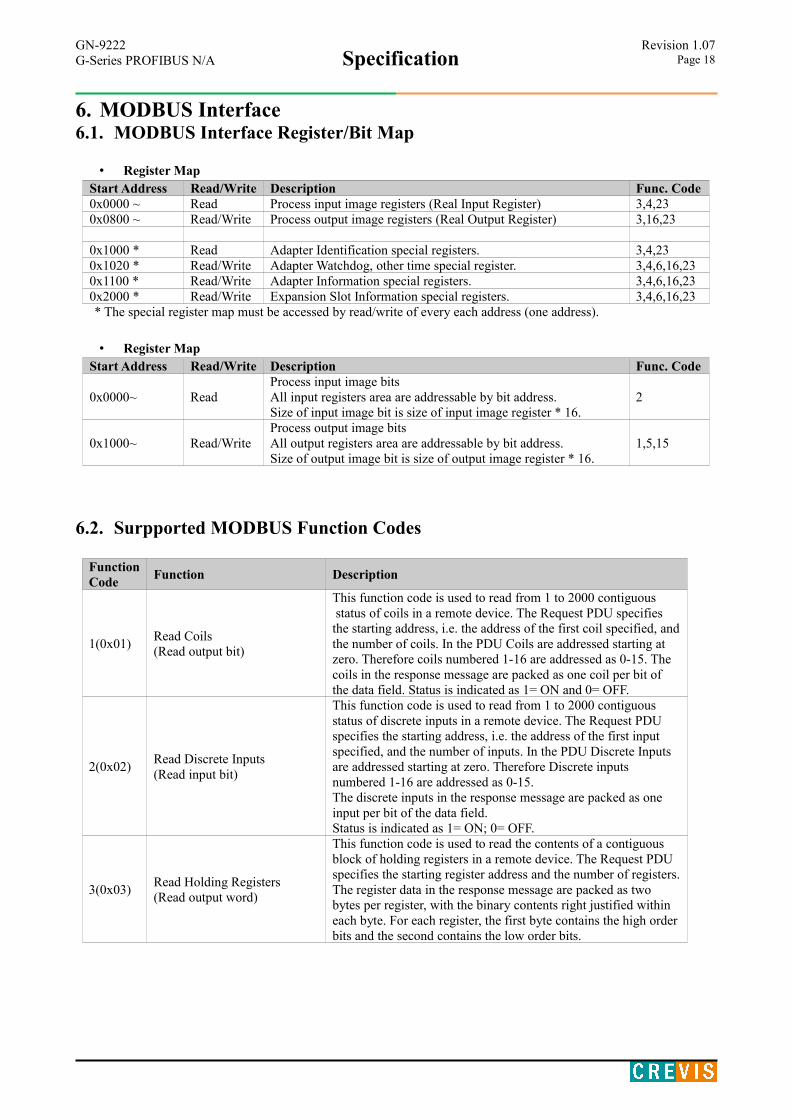
6. MODBUS Interface6.1. MODBUS Interface Register/Bit Map
• Register MapStart Address Read/Write Description Func. Code0x0000 ~ Read Process input image registers (Real Input Register) 3,4,230x0800 ~ Read/Write Process output image registers (Real Output Register) 3,16,23
0x1000 * Read Adapter Identification special registers. 3,4,230x1020 * Read/Write Adapter Watchdog, other time special register. 3,4,6,16,230x1100 * Read/Write Adapter Information special registers. 3,4,6,16,230x2000 * Read/Write Expansion Slot Information special registers. 3,4,6,16,23* The special register map must be accessed by read/write of every each address (one address).
• Register MapStart Address Read/Write Description Func. Code
0x0000~ ReadProcess input image bitsAll input registers area are addressable by bit address.Size of input image bit is size of input image register * 16.
2
0x1000~ Read/WriteProcess output image bitsAll output registers area are addressable by bit address. Size of output image bit is size of output image register * 16.
1,5,15
6.2. Surpported MODBUS Function Codes
FunctionCode
Function Description
1(0x01)Read Coils(Read output bit)
This function code is used to read from 1 to 2000 contiguous status of coils in a remote device. The Request PDU specifies the starting address, i.e. the address of the first coil specified, andthe number of coils. In the PDU Coils are addressed starting at zero. Therefore coils numbered 1-16 are addressed as 0-15. The coils in the response message are packed as one coil per bit of the data field. Status is indicated as 1= ON and 0= OFF.
2(0x02)Read Discrete Inputs(Read input bit)
This function code is used to read from 1 to 2000 contiguous status of discrete inputs in a remote device. The Request PDU specifies the starting address, i.e. the address of the first input specified, and the number of inputs. In the PDU Discrete Inputs are addressed starting at zero. Therefore Discrete inputs numbered 1-16 are addressed as 0-15.The discrete inputs in the response message are packed as one input per bit of the data field.Status is indicated as 1= ON; 0= OFF.
3(0x03)Read Holding Registers(Read output word)
This function code is used to read the contents of a contiguous block of holding registers in a remote device. The Request PDU specifies the starting register address and the number of registers.The register data in the response message are packed as two bytes per register, with the binary contents right justified within each byte. For each register, the first byte contains the high orderbits and the second contains the low order bits.
GN-9222Specification
Revision 1.07G-Series PROFIBUS N/A Page 19
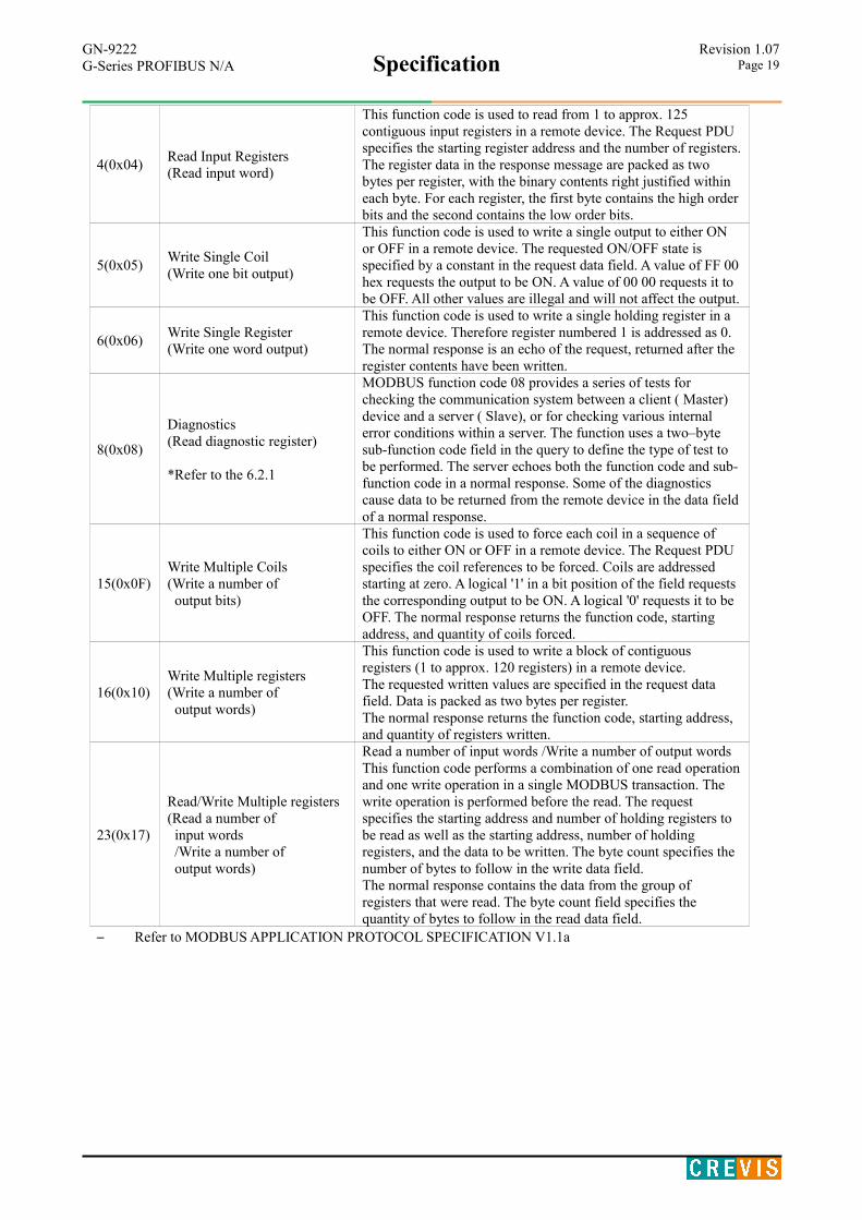
4(0x04)Read Input Registers(Read input word)
This function code is used to read from 1 to approx. 125 contiguous input registers in a remote device. The Request PDU specifies the starting register address and the number of registers.The register data in the response message are packed as two bytes per register, with the binary contents right justified within each byte. For each register, the first byte contains the high orderbits and the second contains the low order bits.
5(0x05)Write Single Coil(Write one bit output)
This function code is used to write a single output to either ON or OFF in a remote device. The requested ON/OFF state is specified by a constant in the request data field. A value of FF 00hex requests the output to be ON. A value of 00 00 requests it to be OFF. All other values are illegal and will not affect the output.
6(0x06)Write Single Register(Write one word output)
This function code is used to write a single holding register in a remote device. Therefore register numbered 1 is addressed as 0. The normal response is an echo of the request, returned after the register contents have been written.
8(0x08)
Diagnostics (Read diagnostic register)
*Refer to the 6.2.1
MODBUS function code 08 provides a series of tests for checking the communication system between a client ( Master) device and a server ( Slave), or for checking various internal error conditions within a server. The function uses a two–byte sub-function code field in the query to define the type of test to be performed. The server echoes both the function code and sub-function code in a normal response. Some of the diagnostics cause data to be returned from the remote device in the data fieldof a normal response.
15(0x0F)Write Multiple Coils(Write a number of output bits)
This function code is used to force each coil in a sequence of coils to either ON or OFF in a remote device. The Request PDU specifies the coil references to be forced. Coils are addressed starting at zero. A logical '1' in a bit position of the field requests the corresponding output to be ON. A logical '0' requests it to be OFF. The normal response returns the function code, starting address, and quantity of coils forced.
16(0x10)Write Multiple registers(Write a number of output words)
This function code is used to write a block of contiguous registers (1 to approx. 120 registers) in a remote device.The requested written values are specified in the request data field. Data is packed as two bytes per register.The normal response returns the function code, starting address, and quantity of registers written.
23(0x17)
Read/Write Multiple registers(Read a number of input words /Write a number of output words)
Read a number of input words /Write a number of output wordsThis function code performs a combination of one read operationand one write operation in a single MODBUS transaction. The write operation is performed before the read. The request specifies the starting address and number of holding registers to be read as well as the starting address, number of holding registers, and the data to be written. The byte count specifies the number of bytes to follow in the write data field.The normal response contains the data from the group of registers that were read. The byte count field specifies the quantity of bytes to follow in the read data field.
– Refer to MODBUS APPLICATION PROTOCOL SPECIFICATION V1.1a

GN-9222Specification
Revision 1.07G-Series PROFIBUS N/A Page 20
6.2.1. 8 (0x08) Diagnostics
Sub-function 0x0000(0) Return Query DataThe data passed in the request data field is to be returned (looped back) in the response. The entire response message should be identical to the request.
Sub-function Data Field (Request) Data Field (Response) Description0x0000(0) Any Echo Request Data
Sub-function 0x0001(1) Restart Communications OptionThe remote device could be initialized and restarted, and all of its communications event counters are cleared. Especially, data field 0x55AA make the remote device to restart with factory default setup of EEPROM.
Sub-function Data Field (Request) Data Field (Response) Description
0x0001(1) 0x0000, 0xFF00 Echo Request Data Reset Only
Sub-function 0x000A(10) Clear Counters and Diagnostic RegisterThe goal is to clear all counters and the diagnostic register. Counters are also cleared upon power–up.
Sub-function Data Field (Request) Data Field (Response) Description0x000A(10) 0x0000 Echo Request Data
Sub-function 0x000B(11) Return Bus Message CountThe response data field returns the quantity of messages that the remote device has detected on the communicationssystem since its last restart, clear counters operation, or power–up.
Sub-function Data Field (Request) Data Field (Response) Description0x000B(11) 0x0000 Total Message Count
Sub-function 0x000D(13) Return Bus Exception Error CountThe response data field returns the quantity of MODBUS exception responses returned by the remote device since itslast restart, clear counters operation, or power–up.Exception responses are described and listed in section 3.2.11.
Sub-function Data Field (Request) Data Field (Response) Description0x000D(13) 0x0000 Exception Error Count
Sub-function 0x000E(14) Return Slave Message CountThe response data field returns the quantity of messages addressed to the remote device, or broadcast, that the remotedevice has processed since its last restart, clear counters operation, or power–up.
Sub-function Data Field (Request) Data Field (Response) Description0x000E(14) 0x0000 Slave Message Count
Sub-function 0x000F(15) Return Slave No Response CountThe response data field returns the quantity of messages addressed to the remote device for which it has returned noresponse (neither a normal response nor an exception response), since its last restart, clear counters operation, orpower–up.
Sub-function Data Field (Request) Data Field (Response) Description0x000F(15) 0x0000 Slave No Response Count
Sub-function 0x0064(100) Return Slave ModBus, Expansion Module StatusThe response data field returns the status of ModBus and expansion module addressed to the remote device.This status values are identical with status 1word of input process image. Refer to 2.4.2.
Sub-function Data Field (Request) Data Field (Response) Description0x0064(100) 0x0000 ModBus, RBUS Status Same as status 1word
GN-9222Specification
Revision 1.07G-Series PROFIBUS N/A Page 21
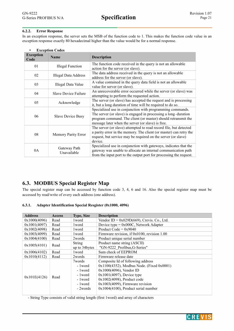
6.2.2. Error ResponseIn an exception response, the server sets the MSB of the function code to 1. This makes the function code value in anexception response exactly 80 hexadecimal higher than the value would be for a normal response.
• Exception CodesException Code
Name Description
01 Illegal FunctionThe function code received in the query is not an allowable action for the server (or slave).
02 Illegal Data AddressThe data address received in the query is not an allowable address for the server (or slave).
03 Illegal Data ValueA value contained in the query data field is not an allowable value for server (or slave).
04 Slave Device FailureAn unrecoverable error occurred while the server (or slave) was attempting to perform the requested action.
05 AcknowledgeThe server (or slave) has accepted the request and is processing it, but a long duration of time will be required to do so.
06 Slave Device Busy
Specialized use in conjunction with programming commands.The server (or slave) is engaged in processing a long–duration program command. The client (or master) should retransmit the message later when the server (or slave) is free.
08 Memory Parity Error
The server (or slave) attempted to read record file, but detected a parity error in the memory. The client (or master) can retry therequest, but service may be required on the server (or slave) device.
0AGateway PathUnavailable
Specialized use in conjunction with gateways, indicates that the gateway was unable to allocate an internal communication path from the input port to the output port for processing the request.
6.3. MODBUS Special Register MapThe special register map can be accessed by function code 3, 4, 6 and 16. Also the special register map must beaccessed by read/write of every each address (one address).
6.3.1. Adapter Identification Special Resgister (0x1000, 4096)
Address Access Type, Size Description0x1000(4096) Read 1word Vendor ID = 0x029D(669), Crevis. Co., Ltd.0x1001(4097) Read 1word Device type = 0x000C, Network Adapter0x1002(4098) Read 1word Product Code = 0x90400x1003(4099) Read 1word Firmware revision, if 0x0100, revision 1.000x1004(4100) Read 2words Product unique serial number
0x1005(4101) ReadStringup to 34bytes
Product name string (ASCII) "GN-9222_Profibus,G-Series"
0x1006(4102) Read 1word Sum check of EEPROM0x1010(4112) Read 2words Firmware release date
0x101E(4126) Read
7words - 1word - 1word - 1word - 1word - 1word - 2words
Composite Id of following address0x1100(4352), Modbus Node. (Fixed 0x0001)0x1000(4096), Vendor ID0x1001(4097), Device type0x1002(4098), Product code0x1003(4099), Firmware revision0x1004(4100), Product serial number
- String Type consists of valid string length (first 1word) and array of characters
GN-9222Specification
Revision 1.07G-Series PROFIBUS N/A Page 22
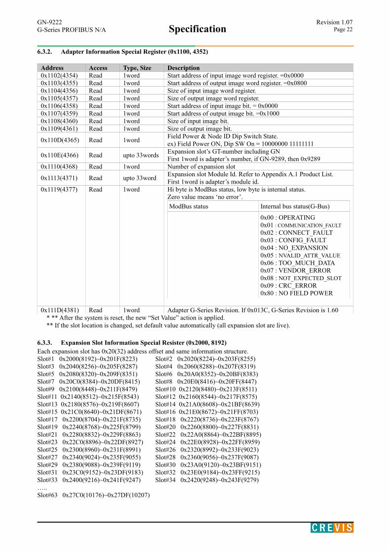
6.3.2. Adapter Information Special Register (0x1100, 4352)
Address Access Type, Size Description0x1102(4354) Read 1word Start address of input image word register. =0x00000x1103(4355) Read 1word Start address of output image word register. =0x08000x1104(4356) Read 1word Size of input image word register.0x1105(4357) Read 1word Size of output image word register.0x1106(4358) Read 1word Start address of input image bit. = 0x00000x1107(4359) Read 1word Start address of output image bit. =0x10000x1108(4360) Read 1word Size of input image bit.0x1109(4361) Read 1word Size of output image bit.
0x110D(4365) Read 1wordField Power & Node ID Dip Switch State.ex) Field Power ON, Dip SW On = 10000000 11111111
0x110E(4366) Read upto 33wordsExpansion slot’s GT-number including GNFirst 1word is adapter’s number, if GN-9289, then 0x9289
0x1110(4368) Read 1word Number of expansion slot
0x1113(4371) Read upto 33wordExpansion slot Module Id. Refer to Appendix A.1 Product List.First 1word is adapter’s module id.
0x1119(4377) Read 1word Hi byte is ModBus status, low byte is internal status. Zero value means ‘no error’.
ModBus status Internal bus status(G-Bus)
0x00 : OPERATING0x01 : COMMUNICATION_FAULT
0x02 : CONNECT_FAULT0x03 : CONFIG_FAULT0x04 : NO_EXPANSION0x05 : NVALID_ATTR_VALUE0x06 : TOO_MUCH_DATA0x07 : VENDOR_ERROR0x08 : NOT_EXPECTED_SLOT0x09 : CRC_ERROR0x80 : NO FIELD POWER
0x111D(4381) Read 1word Adapter G-Series Revision. If 0x013C, G-Series Revision is 1.60* ** After the system is reset, the new “Set Value” action is applied.** If the slot location is changed, set default value automatically (all expansion slot are live).
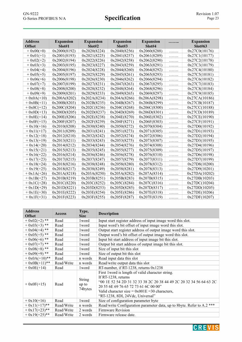
6.3.3. Expansion Slot Information Special Resister (0x2000, 8192)Each expansion slot has 0x20(32) address offset and same information structure.Slot#1 0x2000(8192)~0x201F(8223) Slot#2 0x2020(8224)~0x203F(8255)Slot#3 0x2040(8256)~0x205F(8287) Slot#4 0x2060(8288)~0x207F(8319)Slot#5 0x2080(8320)~0x209F(8351) Slot#6 0x20A0(8352)~0x20BF(8383)Slot#7 0x20C0(8384)~0x20DF(8415) Slot#8 0x20E0(8416)~0x20FF(8447)Slot#9 0x2100(8448)~0x211F(8479) Slot#10 0x2120(8480)~0x213F(8511)Slot#11 0x2140(8512)~0x215F(8543) Slot#12 0x2160(8544)~0x217F(8575)Slot#13 0x2180(8576)~0x219F(8607) Slot#14 0x21A0(8608)~0x21BF(8639)Slot#15 0x21C0(8640)~0x21DF(8671) Slot#16 0x21E0(8672)~0x21FF(8703)Slot#17 0x2200(8704)~0x221F(8735) Slot#18 0x2220(8736)~0x223F(8767)Slot#19 0x2240(8768)~0x225F(8799) Slot#20 0x2260(8800)~0x227F(8831)Slot#21 0x2280(8832)~0x229F(8863) Slot#22 0x22A0(8864)~0x22BF(8895)Slot#23 0x22C0(8896)~0x22DF(8927) Slot#24 0x22E0(8928)~0x22FF(8959)Slot#25 0x2300(8960)~0x231F(8991) Slot#26 0x2320(8992)~0x233F(9023)Slot#27 0x2340(9024)~0x235F(9055) Slot#28 0x2360(9056)~0x237F(9087)Slot#29 0x2380(9088)~0x239F(9119) Slot#30 0x23A0(9120)~0x23BF(9151)Slot#31 0x23C0(9152)~0x23DF(9183) Slot#32 0x23E0(9184)~0x23FF(9215)Slot#33 0x2400(9216)~0x241F(9247) Slot#34 0x2420(9248)~0x243F(9279)…..Slot#63 0x27C0(10176)~0x27DF(10207)
GN-9222Specification
Revision 1.07G-Series PROFIBUS N/A Page 23
AddressOffset
ExpansionSlot#1
ExpansionSlot#2
ExpansionSlot#3
ExpansionSlot#4
…….. ExpansionSlot#63
+ 0x00(+0) 0x2000(8192) 0x2020(8224) 0x2040(8256) 0x2060(8288) ……. 0x27C0(10176)+ 0x01(+1) 0x2001(8193) 0x2021(8225) 0x2041(8257) 0x2061(8289) ……. 0x27C1(10177)+ 0x02(+2) 0x2002(8194) 0x2022(8226) 0x2042(8258) 0x2062(8290) ……. 0x27C2(10178)+ 0x03(+3) 0x2003(8195) 0x2023(8227) 0x2043(8259) 0x2063(8291) ……. 0x27C3(10179)+ 0x04(+4) 0x2004(8196) 0x2024(8228) 0x2044(8260) 0x2064(8292) ……. 0x27C4(10180)+ 0x05(+5) 0x2005(8197) 0x2025(8229) 0x2045(8261) 0x2065(8293) ……. 0x27C5(10181)+ 0x06(+6) 0x2006(8198) 0x2026(8230) 0x2046(8262) 0x2066(8294) ……. 0x27C6(10182)+ 0x07(+7) 0x2007(8199) 0x2027(8231) 0x2047(8263) 0x2067(8295) ……. 0x27C7(10183)+ 0x08(+8) 0x2008(8200) 0x2028(8232) 0x2048(8264) 0x2068(8296) ……. 0x27C8(10184)+ 0x09(+9) 0x2009(8201) 0x2029(8233) 0x2049(8265) 0x2069(8297) ……. 0x27C9(10185)
+ 0x0A(+10) 0x200A(8202) 0x202A(8234) 0x204A(8266) 0x206A(8298) ……. 0x27CA(10186)+ 0x0B(+11) 0x200B(8203) 0x202B(8235) 0x204B(8267) 0x206B(8299) ……. 0x27CB(10187)+ 0x0C(+12) 0x200C(8204) 0x202C(8236) 0x204C(8268) 0x206C(8300) ……. 0x27CC(10188)+ 0x0D(+13) 0x200D(8205) 0x202D(8237) 0x204D(8269) 0x206D(8301) ……. 0x27CD(10189)+ 0x0E(+14) 0x200E(8206) 0x202E(8238) 0x204E(8270) 0x206E(8302) ……. 0x27CE(10190)+ 0x0F(+15) 0x200F(8207) 0x202F(8239) 0x204F(8271) 0x206F(8303) ……. 0x27CF(10191)+ 0x10(+16) 0x2010(8208) 0x2030(8240) 0x2050(8272) 0x2070(8304) ……. 0x27D0(10192)+ 0x11(+17) 0x2011(8209) 0x2031(8241) 0x2051(8273) 0x2071(8305) ……. 0x27D1(10193)+ 0x12(+18) 0x2012(8210) 0x2032(8242) 0x2052(8274) 0x2072(8306) ……. 0x27D2(10194)+ 0x13(+19) 0x2013(8211) 0x2033(8243) 0x2053(8275) 0x2073(8307) ……. 0x27D3(10195)+ 0x14(+20) 0x2014(8212) 0x2034(8244) 0x2054(8276) 0x2074(8308) ……. 0x27D4(10196)+ 0x15(+21) 0x2015(8213) 0x2035(8245) 0x2055(8277) 0x2075(8309) ……. 0x27D5(10197)+ 0x16(+22) 0x2016(8214) 0x2036(8246) 0x2056(8278) 0x2076(8310) ……. 0x27D6(10198)+ 0x17(+23) 0x2017(8215) 0x2037(8247) 0x2057(8279) 0x2077(8311) ……. 0x27D7(10199)+ 0x18(+24) 0x2018(8216) 0x2038(8248) 0x2058(8280) 0x2078(8312) ……. 0x27D8(10200)+ 0x19(+25) 0x2018(8217) 0x2038(8249) 0x2058(8281) 0x2078(8313) ……. 0x27D9(10201)+ 0x1A(+26) 0x201A(8218) 0x203A(8250) 0x205A(8282) 0x207A(8314) ……. 0x27DA(10202)+ 0x1B(+27) 0x201B(8219) 0x203B(8251) 0x205B(8283) 0x207B(8315) ……. 0x27DB(10203)+ 0x1C(+28) 0x201C(8220) 0x203C(8252) 0x205C(8284) 0x207C(8316) ……. 0x27DC(10204)+ 0x1D(+29) 0x201D(8221) 0x203D(8253) 0x205D(8285) 0x207D(8317) ……. 0x27DD(10205)+ 0x1E(+30) 0x201E(8222) 0x203E(8254) 0x205E(8286) 0x207E(8318) ……. 0x27DE(10206)+ 0x1F(+31) 0x201F(8223) 0x203F(8255) 0x205F(8287) 0x207F(8319) ……. 0x27DF(10207)
AddressOffset
AccessType,Size
Description
+ 0x02(+2) ** Read 1word Input start register address of input image word this slot.+ 0x03(+3) ** Read 1word Input word’s bit offset of input image word this slot.+ 0x04(+4) ** Read 1word Output start register address of output image word this slot.+ 0x05(+5) ** Read 1word Output word’s bit offset of output image word this slot.+ 0x06(+6) ** Read 1word Input bit start address of input image bit this slot.+ 0x07(+7) ** Read 1word Output bit start address of output image bit this slot.+ 0x08(+8) ** Read 1word Size of input bit this slot+ 0x09(+9) ** Read 1word Size of output bit this slot+ 0x0A(+10)** Read n words Read input data this slot+ 0x0B(+11)** Read/Write n words Read/write output data this slot+ 0x0E(+14) Read 1word RT-number, if RT-1238, returns 0x1238
+ 0x0F(+15) ReadStringup to 74bytes
First 1word is length of valid character string.If RT-1238, returns“00 1E 52 54 2D 31 32 33 38 2C 20 38 44 49 2C 20 32 34 56 64 63 2C20 55 6E 69 76 65 72 73 61 6C 00 00”Valid character size = 0x001E =30 characters,“RT-1238, 8DI, 24Vdc, Universal”
+ 0x10(+16) Read 1word Size of configuration parameter byte+ 0x11(+17)** Read/Write n words Read/write Configuration parameter data, up to 8byte. Refer to A.2 ***+ 0x17(+23)** Read/Write 2 words Firmware Revision+ 0x19(+25)** Read/Write 2 words Firmware release date.

GN-9222Specification
Revision 1.07G-Series PROFIBUS N/A Page 24
* After the system is reset, the new “Set Value” action is applied. ** Nothing of output, input, memory or configuration parameter corresponding slot returns Exception 02.
6.4. MODBUS ReferenceMODBUS Reference Documents
http://www.modbus.orgMODBUS Tools
http://www.modbustools.com, modbus pollhttp://www.win-tech.com, modscan32


![FnIO G-Series: GN-9481 / GN-9482 / GN-9483Spec] GN-9481_GN...Run-Time System Multiple PLC Tasks Program Languages IEC 61131-3 (LD, IL, ST, FBD, SFC) OPC-Server GN-9481 Not supporting](https://static.fdocuments.net/doc/165x107/5fcf359602c376594f0af992/fnio-g-series-gn-9481-gn-9482-gn-9483-spec-gn-9481gn-run-time-system-multiple.jpg)