Flutter' 'Analysis of an Airplane With Multiple Structural · The nonlinear flutter equations can...
40
NASA Technical Paper LOAN COW: RElURN TO AWL TECHNICAL LIBRARY KIRTLAND AFB, N.M. 1620 Flutter' 'Analysis of anAirplane With Multiple Structural TP 1620 c. I 1 >, ' Nonlinearities in the Control. - System Elmar J. Breitbach MARCH 1980 https://ntrs.nasa.gov/search.jsp?R=19800015832 2020-03-10T10:25:06+00:00Z
Transcript of Flutter' 'Analysis of an Airplane With Multiple Structural · The nonlinear flutter equations can...

NASA Technical Paper
LOAN COW: RElURN TO AWL TECHNICAL LIBRARY KIRTLAND AFB, N.M.
1620
Flutter' 'Analysis of an Airplane With Multiple Structural
TP 1620 c. I
1
> , ' Nonlinearities in the Control. - System
Elmar J. Breitbach
MARCH 1980
https://ntrs.nasa.gov/search.jsp?R=19800015832 2020-03-10T10:25:06+00:00Z

I I TECH LIBRARY KAFB. NY
NASA Technical Paper 1620
Flutter Analysis of an Airplane With Multiple Structural Nonlinearities in the Control System
Elmar J. Breitbach Latlgley Research Ceuter Hunzptorr, Virgiuia
National Aeronautics and Space Administration
Scientific and Technical Information Office
1980
SUMMARY
Experience has shown that the flutter prediction process for airplanes can be greatly affected by strong concentrated nonlinearities which may be local- ized in the linking elements of the control mechanism, in the pivot joints of variable-sweep-wing systems, and in the connecting points between wing- and pylon-mounted external stores. The principle of equivalent linearization offers an efficient possibility for solving the related nonlinear flutter equa- tions in the frequency domain as a complement to the well-known time domain procedures. Taking as an example an airplane with nonlinear control character- istics, it is demonstrated how the equivalent linearization approach can be extended to rather complicated systems with multiple sets of strongly inter- acting, concentrated nonlinearities.
INTRODUCTION
Routine flutter analyses generally imply linearized representation of both the structural and the aerodynamic properties. This approximation has proved to be a useful basis for the flutter clearance of a large number of aircraft prototypes. There remains, nevertheless, a significant number of flutter cases suffering from rather poor agreement between analysis and test results. Many of these disagreements can be traced to structural nonlinearities. A survey of the various types of structural nonlinearities, their physical sources, and their effects on aircraft vibration and flutter is given in reference 1, which indicates that strong concentrated nonlinearities are a common feature of the control systems of mechanically controlled airplanes. From reference 2, which presents a new experimental-numerical approach to determining the dynamic char- acteristics of hydraulic aircraft control actuators, it becomes obvious that flutter of aircraft with hydraulic controls may also be greatly affected by strong concentrated nonlinearities. References 3 and 4 focus on the special case of a modern variable-sweep-wing fighter airplane with concentrated non- linearities in the wing pivot mechanism and in the corresponding single-point external store suspension system. Reference 5 and, in particular, reference 6 describe several concepts of how the governing equations of airplanes with con- trol system nonlinearities can conveniently be formulated in terms of consis- tent sets of both measured modal data and nonlinear force-deflection diagrams. The nonlinear flutter equations can be solved in the time domain by using ana- log computer techniques (see refs. 5 and 7) or by numerical integration. In addition to this time domain approach, promising attempts have been made to solve nonlinear flutter problems in the frequency domain by employing the prin- ciple of equivalent linearization (see ref. 8 ) . The effectiveness and accuracy of this equivalent linearization approach were impressively demonstrated for a semispan wing-aileron model with a single nonlinearity in the aileron hinge; the calculated and the wind-tunnel test results agreed very well (see ref. I ) .
Application of the equivalent linearization approach to systems with more than one nonlinearity creates some additional, though still solvable, difficul-
ties. These difficulties are associated with an incompatibility between the input data representing the equivalent stiffness and damping properties of the nonlinearities involved and the corresponding output deflections. In coping with this problem, a recent investigation (ref. 9) describes the application of a method called the describing function method’ (ref. 10) to the special case of a flexible missile control surface with simple undamped free-play non- linearities in both the roll and pitch degree of freedom of the root support stiffness.
The particular concern of the present study is the extension of the equiv- alent linearization concept to the flutter analysis of complete airplanes with strong hysteresis-type nonlinearities in the control system. Antisymmetrical flutter of a sailplane involving strongly interacting rudder and aileron non- linearities is used as a realistic example to demonstrate the applicability of the method proposed.
SYMBOLS
A,B,C mass, damping, and stiffness matrices, respectively, defined in terms of physical deflections
b viscous damping coefficient of control surface hinge
C stiffness coefficient of control surface hinge
f frequency , w/Zrr
F force or moment acting on control surface
9 absolute amplitude value, see equation (31)
h bending deflection of quarter-chord line of lifting surface
j imaginary unit, 0 II ha If -chor d leng th
Mf flight Mach number
M,D,K generalized mass, damping, and stiffness matrices, respectively
AM,AD,AK generalized matrices of mass, damping, and stiffness changes, respectively
lA slightly modified form of the equivalent linearization approach.
2

N
P
9
Q
R
t
U
V
01
B
Y
r 8
5
11
A
P
T
@
@
w
number of controls involved i n f lut ter case
column matrix of external forces
colum matrix of generalized coordinates
column matrix of generalized forces
matrix of unsteady aerodynamic forces R r related to normal modes Qr
time
column matrix of physical deflections
f l i g h t speed
rotation about quarter-chord ,line of lifting surface
control surface rotation about hinge line
damping loss angle, 25
diagonal matrix of damping loss angles
matching function, see equation ( 3 0 )
damping expressed as ratio to cri t ical damping
absolute amplitude value, see equation (29)
diagonal matrix of square values of circular normal frequencies Wr = 2Tfr
air density
control surface chord length ratio (see fig. 11 )
integration variable, (fit
modal matrix of normal modes 6,
circular frequency
Subscripts :
A aileron properties
L linear properties
NL nonlinear properties
3

r normal mde index, r = 1 , 2, . . ., n
R rudder properties
VrFI,(J i nd ices of concen t r a t ed non l inea r i t i e s i nvo lved
Superscr ip ts :
F f l u t t e r speed
. T t ransposed mat r ix
0 s t a r t i n g v a l u e s
NONLINEAR EQUATIONS OF MOTION
Reference 6 o f f e r s a cho ice o f s eve ra l modal syn thes i s concep t s which can convenient ly be used to e s t a b l i s h t h e aeroelastic equat ions o f mot ion for the f l u t t e r a n a l y s i s of a i rp lanes wi th s t rong concent ra ted cont ro l sys tem nonl in- ear i t ies . In accordance with one of these concepts (concept I1 of ref. 6) , t h e o r i g i n a l l y n o n l i n e a r a i r p l a n e structure is phys ica l ly conve r t ed to an a r t i f i - c i a l l y l i n e a r i z e d test conf igu ra t ion by rep lac ing the nonl inear e lements by l i n e a r s t i f f n e s s e s w i t h low damping. The normal mode c h a r a c t e r i s t i c s of the l i n e a r i z e d test conf igu ra t ion s e rve as a c o n s i s t e n t basis f o r t h e c a l c u l a t i o n of both the unsteady aerodynamic reactions and a set of nonl inear coupl ing terms re t ransforming the test conf igu ra t ion to the ac tua l sys tem. The nonlin- earit ies can be d e t e r m i n e d s t a t i c a l l y i n t h e form of force-deflection diagrams or dynamically by direct measurement of equ iva len t stiffness and damping values versus v ibra t ion ampl i tude . The equat ions of motion of the mod i f i ed l i nea r i zed test conf igura t ion , formula ted in terms of p h y s i c a l d e f l e c t i o n s , c a n be w r i t t e n in ma t r ix no ta t ion as fol lows:
.. AU + BLU + CLU = P (1 1
where
A
BL
CL
P
U
mass matr ix
v iscous damping ma t r i x
s t i f f n e s s m a t r i x
column mat r ix of ex terna l forces , for ins tance , uns teady aerodynamic fo rces
column mat r ix o f phys i ca l de f l ec t ions ; u and u are f irst- and second-o rde r d i f f e ren t i a l s w i th r e spec t to time t
The dynamic behavior of t h e unchanged nonl inear system may be descr ibed by
Au + B; + Cu = P (2) ..
4
I
where
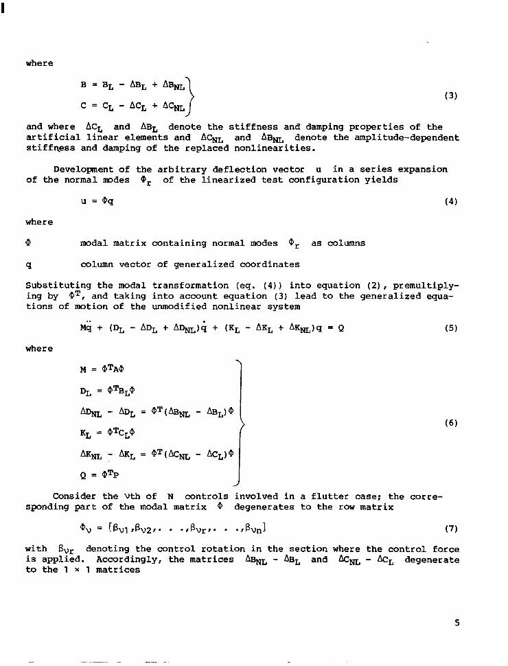
B = BL - ABL + AB& (3 )
C = CL - ACL + A C m
and where ACL and ABL denote the stiffness and damping properties of the artificial linear elements and ACNL and AB& denote the amplitude-dependent stiffnpss and damping of the replaced nonlinearities.
Development of the arbitrary deflection vector u in a series expansion of the normal m d e s 0, of the linearized test configuration yields
u = @q (4 )
where
@ modal matrix containing normal modes Qr as columns
9 column vector of generalized coordinates
Substituting the modal transformation (eq. (4)) into equation (2), premultiply- ing by QT, and taking into account equation (3) lead to the generalized equa- tions of motion of the unmodified nonlinear system
where
M = (PTA@ 7
with Bur denoting the control rotation in the section where the control force is applied. Accordingly, the matrices A%L - ABL and &NL - LkL degenerate to the 1 x 1 matrices
5

%L,V - &L,V = h L , V ( B V ) - bL,V
&m,v - &L,V = cNL,v(Bv) - CL,V 1 where cL,v and bL,V d e f i n e t h e a r t i f i c i a l h i n g e s t i f f n e s s a n d damping of t h e V t h c o n t r o l surface and %L, v ( Bv) and h, ( By) def ine the ampl i tude- dependen t s t i f fnes s and damping of the replaced n o n l i n e a r i t y o f t h e v t h c o n t r o l s u r f ace. Hence,
N N
V=l V=l AKNL - k L = E (&m,v - M L , ~ ) = x avTrm,v(Bv) - c L , v ~ ~ v
The normal modes Qr of the l i n e a r i z e d test c o n f i g u r a t i o n s a t i s f y t h e n a l i t y c o n d i t i o n ,
QTA@ = M
aTCL@ = ALM = RL
where
or t hogo-
M d iagonal mat r ix o f genera l ized masses M,
KL d iagonal mat r ix o f genera l ized s t i f fnesses K L , ~ = W L , ~ M ~
AL diagonal matr ix of square values of c i rcu lar normal f requencies uLl r
2
The genera l ized damping ma t r ix DL, which is no t necessa r i ly d i agona l , was def ined in equa t ion (6) . Without damping coupl ing, matr ix DL also becomes d iagonal wi th the genera l ized damping elements D L , ~ .
The unsteady aerodynamic forces P g e n e r a l l y depend on time t, f l i g h t Mach number M f , f l i g h t s p e e d V, and a i r d e n s i t y P. Developing P i n a series expansion of unsteady aerodynamic forces Rr related to the normal modes or leads to
Q = QT R(Mf ,V ,P , t ) q (11)
where
AS ment ioned prev ious ly , appl ica t ion of the equiva len t l inear iza t ion approach to non l inea r f l u t t e r p rob lems r equ i r e s a t ransformat ion of t h e d i f f e r e n t i a l equat ion (5) i n t o t h e f r e q u e n c y domain. Accordingly, by assuming simple har- monic motions,
6
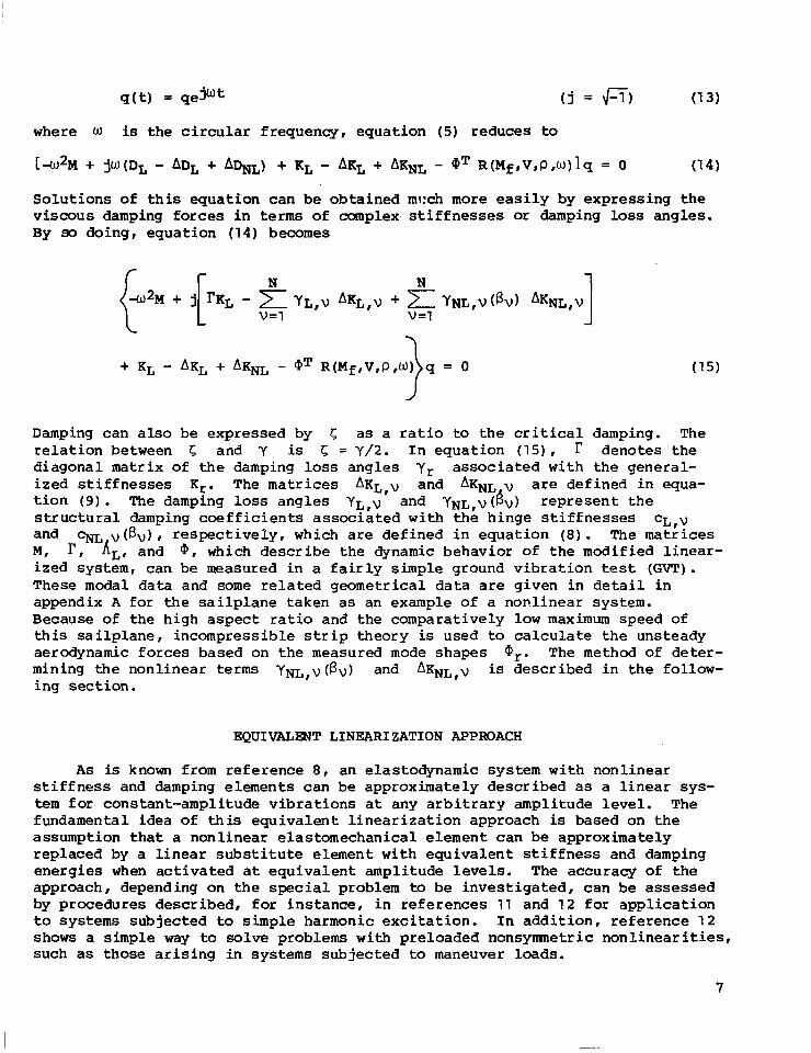
q ( t ) = qe j w t ( j = 4 7 ) (1 3)
where W is the c i r cu la r f r equency , equa t ion (5) reduces to
[ a 2 M + jU(DL - ADL + A h L ) + KL - AKL + AKNL - QT R ( M f , V , P , u ) ] q = 0 (1 4)
Solu t ions of t h i s e q u a t i o n c a n be obta ined v iscous damping forces i n terms of complex By 90 doing, equat ion (14) becomes
r N
L V=l
mcch more e a s i l y by expres s ing t he s t i f f n e s s e s or damping loss angles .
N 1
Damping can also be expressed by 5 a s a r a t io to t h e c r i t i ca l damping. The r e l a t i o n between 5 and Y is 5 = Y/2. I n equat ion (15) , denotes the d iagonal mat r ix o f the damping loss angles yr associated wi th t h e general- i z e d s t i f f n e s s e s Kr. The matrices A K ~ , v and AKNL v are de f ined i n equa- t i o n ( 9 ) . The damping loss angles YL,v and Y N L , ~ ( 6 ~ ) r ep resen t t h e s t r u c t u r a l damping c o e f f i c i e n t s associated w i t h t he h i n g e s t i f f n e s s e s CL,V and ~ N L v ( B v ) , r e spec t ive ly , which are de f ined i n equa t ion ( 8 ) . The matrices M, r , AL, and @, which describe t h e dynamic behavior of the modified l i nea r - ized system, can be measured in a f a i r l y simple ground vibrat ion test (GVT) . These modal data and some related geometr ical data are g iven i n de t a i l i n appendix A for t h e s a i l p l a n e t a k e n as an example of a nonlinear system. Because of t he high aspect ratio and the comparat ively l o w maximum speed of t h i s s a i l p l a n e , i n c o m p r e s s i b l e s t r i p t h e o r y is used to calculate t h e unsteady aerodynamic forces based on t h e measured mode shapes Qr. The method of deter- mining the nonl inear terms YNL,~(BV) and AKNL,~ is described i n t h e follow- ing sec t ion .
EQUIVALENT LINEARIZATION APPROACH
As is known from re fe rence 8 , an elastodynamic system with nonlinear s t i f f n e s s and damping elements can be approximately described as a l i nea r sys - tem for constant-ampli tude vibrat ions a t any a rb i t ra ry ampl i tude l eve l . The fundamental idea of t h i s e q u i v a l e n t l i n e a r i z a t i o n a p p r o a c h is based on the assumption that a nonl inear e las tomechanical e lement can be approximately replaced by a l i n e a r substitute e l emen t w i th equ iva len t s t i f fnes s and damping energ ies when a c t i v a t e d a t equ iva len t ampl i tude l eve l s . The accuracy of t h e approach, depending on the special problem to be inves t iga t ed , can be assessed by procedures descr ibed, for in s t ance , i n r e f e rences 1 1 and 12 for a p p l i c a t i o n to systems subjected to simple ha rmon ic exc i t a t ion . In add i t ion , r e f e rence 12 shows a simple way to solve problems with preloaded nonsymnet r ic nonl inear i t ies , such as those a r i s ing i n sys t ems sub jec t ed to maneuver loads.
7

I n accordance wi th reference 8 the equivalent linear coefficients of a nonlinear force-deflection diagram can be calculated from
where cm(B) and YNL(B) define the complex stiffness,
and where the force F is a nonlinear function of the deflection f3. Inte- gration is carried out over a f u l l period of oscillation using 4 = w t as integration variable.
I n view of the particular flutter case to be dealt w i t h subsequently, two special types of bilinear force-deflection diagrams, sketched i n figures 1 and 2, are evaluated by means of equation (16) . The diagram i n figure 1 is characterized by a low stiffness cl for
-B1 6 f3 6 B1 (1 8)
where B1 denotes the amplitude corresponding to the maximum stroke of the control surf ace. For
the stiffness assumes t h e much higher value c 2 because of kinematic limita- tion beyond the blocking p o i n t (see f igs . 1 and 2 ) . Hence it follows that
where
B1 41 = arcsin -
B
Figure 2 i l lustrates a bilinear hysteresis-type force-deflection diagram. For amplitudes belaw the blocking point according to equation ( l a ) , the equivalent stiffness and damping values are
8

where
c2 “(249 - sin 241 ) 21r
where FO is defined in figure 2. For amplitudes beyond the blocking point according to equation (19), the equivalent stiffness and damping values are
where
2B0 - B1 $1 = arccos
B
$1 42 = arcsin -
B J where Bo is defined in figure 2.
SOLUTION OF THE NONLINEAR FLUTTER EQUATIONS
Equation (15), which is usually written in the form of a complex eigen- value problem, can be solved for an arbitrary set of N equivalent stiffness and damping values qL,v (Bv) and Y&,v(&) which, because of their amplitude dependency, correspond to a definite set of deflections BvO. Stan- dard flutter calculation techniques can be applied to determine the flutter boundary which is generally characterized by an undamped harmonic oscillation of one of the generalized degrees of freedan. The corresponding generalized eigenvector qrF can be transformed into the physical deflections:
UF = QqrF

The d e f l e c t i o n s ByP of t h e d i f f e r e n t c o n t r o l s u r f a c e s w i t h n o n l i n e a r elements which are part of t h e f l u t t e r mode shape uF can be determined by
By' = QyqrF (V = 1 , 2 , . . ., N) (27)
The d e f l e c t i o n s ByF r ep resen t a c o n s i s t e n t set of s o l u t i o n s i f and only i f the fo l luwing condi t ion is satisfied:
nvF - nvo = 0 (V = 1, 2, . . ., N) (28)
where
5 0 = I BVO I rlvF = ]BvFI (29)
I n f u l f i l l i n g c o n d i t i o n ( 2 8 ) , t h e f o l l o w i n g i t e r a t i v e p r o c e d u r e may be employed. I n a f i r s t step a set of ampli tudes nvo corresponding to a set of e q u i v a l e n t s t i f f n e s s and damping va lues GL,V and y&,v, r e spec t ive ly , is selected as inpu t data f o r a n i n i t i a l f l u t t e r c a l c u l a t i o n . A t t h e f l u t t e r speed r e s u l t i n g from t h i s c a l c u l a t i o n , t h e related f l u t t e r mode d e f l e c t i o n s BVF can be c a l c u l a t e d by means of equat ion ( 2 7 ) . The d i f f e r e n c e between t h e i n i t i a l a m p l i t u d e s nvo and t h e f l u t t e r mode amplitudes nvF, both of which are def ined by equat ion (29 ) , can be set i n t o t h e more extended form
where
which means t h a t t h e amplitude of t h e pth nonl inear e lement is kept cons t an t for a l l f u r t h e r c a l c u l a t i o n s ; t h a t is,
gpF = '1po (32)
To determine an optimal change Allv of the s t a r t i n g v a l u e s nvo for t h e next i t e r a t i o n step, E is s u c c e s s i v e l y d i f f e r e n t i a t e d wi th respect to the ampli- tudes nvo:
10
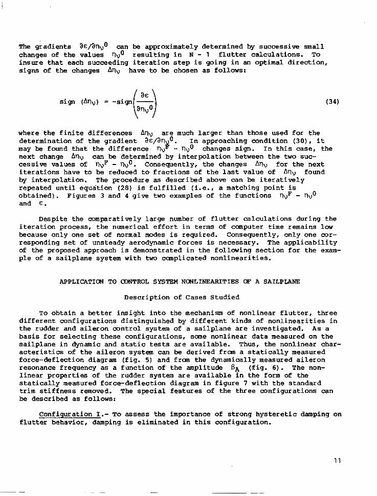
The g rad ien t s aS/aTlvo can be approximately determined by success ive small changes of the values rlvo r e s u l t i n g i n N - 1 f l u t t e r c a l c u l a t i o n s . To insu re t ha t each succeed ing i t e r a t ion step is g o i n g i n an optimal d i r e c t i o n , -
s i g n s of the changes Arlv have to
w h e r e t h e f i n i t e d i f f e r e n c e s A r l ~
be chosen as follows:
(34)
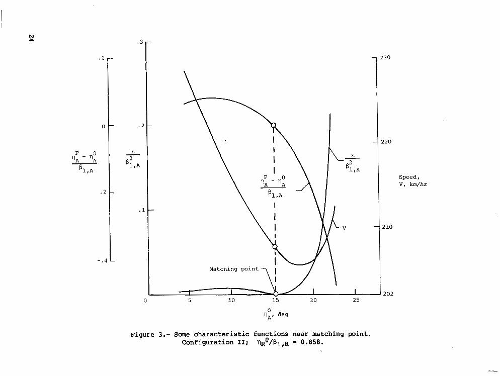
are much l a rge r t han those used for the de te rmina t ion of the g rad ien t a€/arl$o. In approaching condi t ion ( 3 0 ) , it may be found t ha t t he d i f f e rence rlv - rlvo changes sign. I n t h i s case, the next change Arlv can be determined by interpolation between t h e two suc- cessive values of rlvF - rlvo. Consequently, the changes Arlv fo r t he nex t i t e r a t i o n s h a v e to be reduced to f r a c t i o n s of t h e l a s t value of Arlv found by in t e rpo la t ion . The procedure as described above can be i t e r a t i v e l y repea ted un t i l equa t ion (28) is f u l f i l l e d (i.e., a matching point is obta ined) . F igures 3 and 4 g ive t w o examples of the functions rlyF - rlvo and E .
Despi te the compara t ive ly l a rge number of f l u t t e r ca l cu la t ions du r ing t h e i t e r a t ion p rocess , t he numer i ca l effor t i n terms of canputer time remains low because only one set of normal modes is required. Consequently, only one cor- responding set of unsteady aerodynamic forces is necessary. The a p p l i c a b i l i t y of the proposed approach is demonst ra ted in the fo l lowing sec t ion for t he exam- ple of a sa i lp l ane sys t em wi th two canplicated n o n l i n e a r i t i e s .
APPLICATION TO OONTROL SYSTEM NONLINEARITIES OF A SAILPLANE
Desc r ip t ion of Cases S tud ied
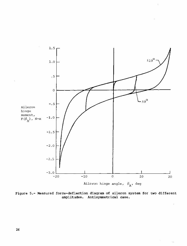
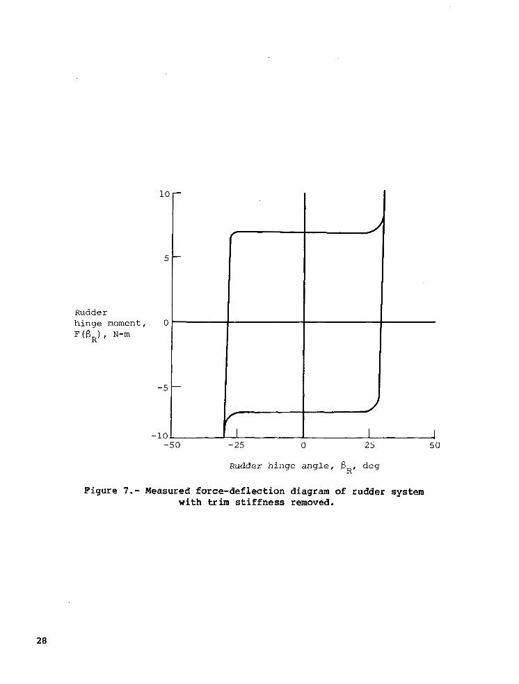
To ob ta in a better i n s i g h t i n t o t h e mechanism of n o n l i n e a r f l u t t e r , three d i f f e r e n t c o n f i g u r a t i o n s d i s t i n g u i s h e d by d i f f e r e n t k i n d s of n o n l i n e a r i t i e s i n the rudder and a i leron control system of a s a i l p l a n e are inves t iga t ed . A s a basis f o r s e l e c t i n g t h e s e c o n f i g u r a t i o n s , sane nonl inear data measured on t he s a i l p l a n e i n dynamic and s t a t i c tests are avai lable . Thus, the nonl inear char- acteristics of the a i le ron sys tem can be d e r i v e d f r a n a s t a t i c a l l y m e a s u r e d force-def lec t ion d iagram ( f ig . 5) and f ran the dynamica l ly measured a i l e r o n resonance frequency as a func t ion of the ampl i tude BA ( f i g . 6) . The non- l i n e a r properties of the rudder system are a v a i l a b l e i n the form of the s t a t i c a l l y measured fo rce -de f l ec t ion d i ag ram in f i gu re 7 wi th t he s t anda rd trim s t i f f n e s s removed. The special f ea tu res o f t he t h ree conf igu ra t ions can be described as follows:
Configurat ion I.- T o assess the impor tance o f s t rong hys te re t ic damping on f l u t t e r b e h a v i o r , damping is e l i m i n a t e d i n t h i s conf igura t ion .
11
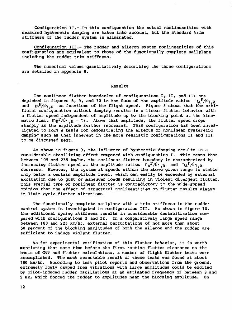
Configurat ion 11.- I n t h i s c o n f i g u r a t i o n t h e a c t u a l n o n l i n e a r i t i e s w i t h measured hys te re t ic damping are t aken i n to accoun t , bu t t he s t anda rd trim s t i f f n e s s of the rudder system is el iminated.
Conf igura t ion 111.- The rudder and a i le ron sys tem nonl inear i t ies of t h i s conf igu ra t ion are equ iva len t to those of t h e f u n c t i o n a l l y complete s a i l p l a n e inc luding the rudder trim s t i f f n e s s .
The numer ica l va lues quant i ta t ive ly descr ib ing the th ree conf igura t ions are detailed in appendix B.
Res u l ts
The nonl inear f lu t te r boundaries of configurat ions I , 11, and I11 are depicted i n f i g u r e s 8, 9 , and 10 i n t he form of t h e amplitude ratios ' I A ~ / B ~ ,A and I ' - I R ~ / ~ ~ ,R as f u n c t i o n s of t h e f l i g h t s p e e d . F i g u r e 8 shows t h a t t h e ar t i - f i c i a l c o n f i g u r a t i o n w i t h o u t damping r e s u l t s i n a l i n e a r f l u t t e r b e h a v i o r w i t h a f lu t t e r speed i ndependen t of amplitude up to the b lock ing po in t a t the kine- matic l i m i t ( T ~ R ~ / B ~ ,R = 1 ) . Above tha t ampl i tude , the f l u t t e r speed drops sha rp ly as the ampl i tude fur ther increases . This conf igura t ion has been inves- t i g a t e d to form a b a s i s f o r d e m o n s t r a t i n g t h e e f f e c t s o f n o n l i n e a r h y s t e r e t i c damping such as t h a t i n h e r e n t i n t h e more real is t ic conf igu ra t ions I1 and I11 t o be d iscussed next .
A s shown i n f i g u r e 9, t h e i n f l u e n c e of h y s t e r e t i c damping results i n a m n s i d e r a b l e s t a b i l i z i n g e f f e c t compared wi th conf igu ra t ion I. Th i s means t h a t between 195 and 235 km/hr, t he non l inea r f l u t t e r boundary is cha rac t e r i zed by i n c r e a s i n g f l u t t e r speed as the amplitude ratios T l ~ ~ f i 1 ,R and T l ~ ~ / 6 1 ,A decrease. However, the sys tem a t speeds wi th in the above g iven range is s t a b l e on ly belaw a c e r t a i n a m p l i t u d e l e v e l , which can e a s i l y be exceeded by e x t e r n a l exc i t a t ion due to g u s t or maneuver loads r e s u l t i n g i n v i o l e n t d i v e r g e n t f l u t t e r . Th i s special type of n o n l i n e a r f l u t t e r is c o n t r a d i c t o r y t o the wide-spread o p i n i o n t h a t t h e e f f e c t of s t ructural n o n l i n e a r i t i e s o n f l u t t e r results always i n limit c y c l e f l u t t e r v i b r a t i o n s .
The f u n c t i o n a l l y complete s a i l p l a n e w i t h a trim s t i f f n e s s i n t h e r u d d e r control system is i n v e s t i g a t e d i n c o n f i g u r a t i o n 111. As shown i n f i g u r e 1 0 , t h e a d d i t i o n a l s p r i n g s t i f f n e s s results i n c o n s i d e r a b l e d e s t a b i l i z a t i o n com- pared wi th conf igura t ions I and 11. I n a mmpara t ive ly l a rge speed range between 180 and 225 km/hr, e x t e r n a l p e r t u r b a t i o n s of no t more than about 50 percen t of the b locking amplitudes of bo th the a i le ron and the rudder are s u f f i c i e n t to i n d u c e v i o l e n t f l u t t e r .
A s f o r e x p e r i m e n t a l v e r i f i c a t i o n o f t h i s f l u t t e r b e h a v i o r , it is worth ment ioning tha t sane time before t h e f i r s t r o u t i n e f l u t t e r c learance on the basis of GVT and f l u t t e r c a l c u l a t i o n s , a number of f l i g h t f l u t t e r tests were accanpl ished. The most remarkable r e s u l t o f t h e s e tests was found a t about 180 km/hr. According to test pi lot reports and observa t ions f ran the g round, extremely lowly damped f r ee v ib ra t ions w i th l a rge ampl i tudes cou ld be e x c i t e d by p i lo t - induced rudde r o sc i l l a t ions a t an estimated frequency of between 3 and 5 Hz, which fo rced t he rudde r to amplitudes near the blocking amplitude. On
12

the basis of figure 10, a small increment in speed would have resulted in violent flutter. It should be mentioned that the flutterlike vibrations were eliminated by mass-balancing the rudder.
CONCLUDING REMARKS
Based on standard flutter calculation techniques in the frequency domain and on the equivalent linearization approach, a method has been developed to predict the flutter behavior of complete airplanes with multiple sets o€ concentrated nonlinearities. The applicability of the method has been demon- strated for the example of antisymmetrical flutter of a sailplane with nonlin- earities in its control systems. The results are in good agreement with obser- vations during actual flight tests of the sailplane.
In future investigations, emphasis should be placed on the following problems:
1 . Investigation of service-life-dependent alterations of concentrated structural nonlinearities.
2. Investigation of mass, damping, and stiffness alterations due to pilot feedback
3. Amendment of ground vibration test methods and flight and wind-tunnel flutter test techniques by paying more attention to nonlinear effects
4. Developnent of suitable methods for the calculation of unsteady aerody- namic forces in the time domain for all flight speed ranges
5 . Application of digital and analog time domain techniques to solve tran- sient problems such as those due to gust loads, maneuver loads, and sudden failure of control system devices
6. Investigation of the frequency-dependent dynamic properties of non- linear elements
7. Investigation of nonlinear effects on design, test, and operation of flutter suppression and vibration reduction systems
Langley Research Center National Aeronautics and Space Administration Hampton, VA 23665 February 8, 1980
1 3

APPENDIX A
MODAL DATA OF A SAILPLANE IN A MODIFIED LINEARIZED TEST CONFIGURATION
To obtain a largely linear test configuration, the nonlinear elements in the aileron, rudder, and elevator control mechanisms of a sailplane were replaced by linear lcwly damped spring elements. A, sketch of the sailplane investigated and the strip arrangement used to calculate the unsteady aerody- namic forces is shown in figure 11. Tables I, 11, and I11 list the five lowest antisymmetrical normal modes and the geometrical data of the strip scheme. As shown in figure 11, the normal mode displacements referring to the midstrip sections are split up into the quarter-chord point bending deflection h, tor- sion a, and control surface rotation B . The generalized masses M,, the nor- mal frequencies f I: = Ur/m, and the damping loss angles Yr are listed in table IV.
Since this investigation is of an antisymmetrical flutter case, only the rudder control system and the aileron control system must be taken into account. Correspondingly, in accordance with equation ( 7 ) , only the row matrices QR and QA describing the antisymmetrical hinge rotation angles B R , ~ and B A , ~ of the rudder and the aileron (v = R,A) are given in table V.
14

APPENDIX B
QUANTITATIVE DETERMINATION OF NONLINEAR CHARACTERISTICS OF
CONFIGURATIONS I , 11, AND I11
Configurat ion I
The fo l lowing va lues are chosen fo r desc r ib ing t he non l inea r i t i e s o f bo th the rudder and the a i leron system by b i l i n e a r z e r o damping fo rce -de f l ec t ion diagrams such as those shown i n f i g u r e 1 :
c1 ,A = 10 N-m/rad c1 ,R =
C2,A = 500 N-m/rad C ~ , R = 500 N-m/rad
61 ,A = 20° 61 ,R = 30°
The s t i f f n e s s e s c 2 ,A, C l , R , and C ~ , R are estimated from f i g u r e s 5 and 7, r e s p e c t i v e l y . S t i f f n e s s C1,A can be approximately calculated from
where
M2 genera l ized mass of normal mode r = 2 (see table I V )
TA ra t io of a i l e r o n chord length to wing chord length a t inboard edge -
o f a i l e r o n
36 half-chord length of the wing a t inboard edge of ai leron
fA,min minimum resonance frequency of a i le ron sys tem (see f i g . 6)
Applicat ion of equat ion ( B l ) implies t h a t t h e normal mode r = 2 fundamentally cons is t s o f mot ion of the a i le ron sys tem (see tables I, 11, and 111). The e q u i v a l e n t s t i f f n e s s e s c + J L , A ( ~ ) and CNL,R(B) of the a i le ron and the rudder system calculated by means of equat ion (20) are shown i n f i g u r e 12.
Configurat ion I1
This conf igura t ion is cha rac t e r i zed by hys te res i s - type force-def lec t ion diagrams in both the a i le ron and the rudder system. The fo rce -de f l ec t ion dia- gram of the rudder sys tem shown i n f i g u r e 7 can be approximated by a b i l i n e a r diagram of the k ind ske t ched i n f i gu re 2. Because the trim s t i f f n e s s is elimi- n a t e d i n t h i s c o n f i g u r a t i o n , t h e f o l l o w i n g q u a n t i t a t i v e data can be selected:
15
I
APPENDIX B
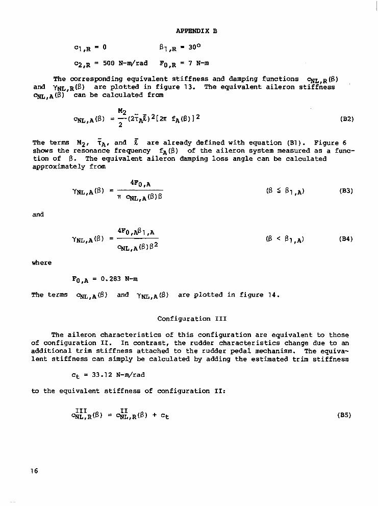
c1 ,R = B1 ,R = 30°
C2 ,R = 500 N-drad FO ,R = 7 N-m
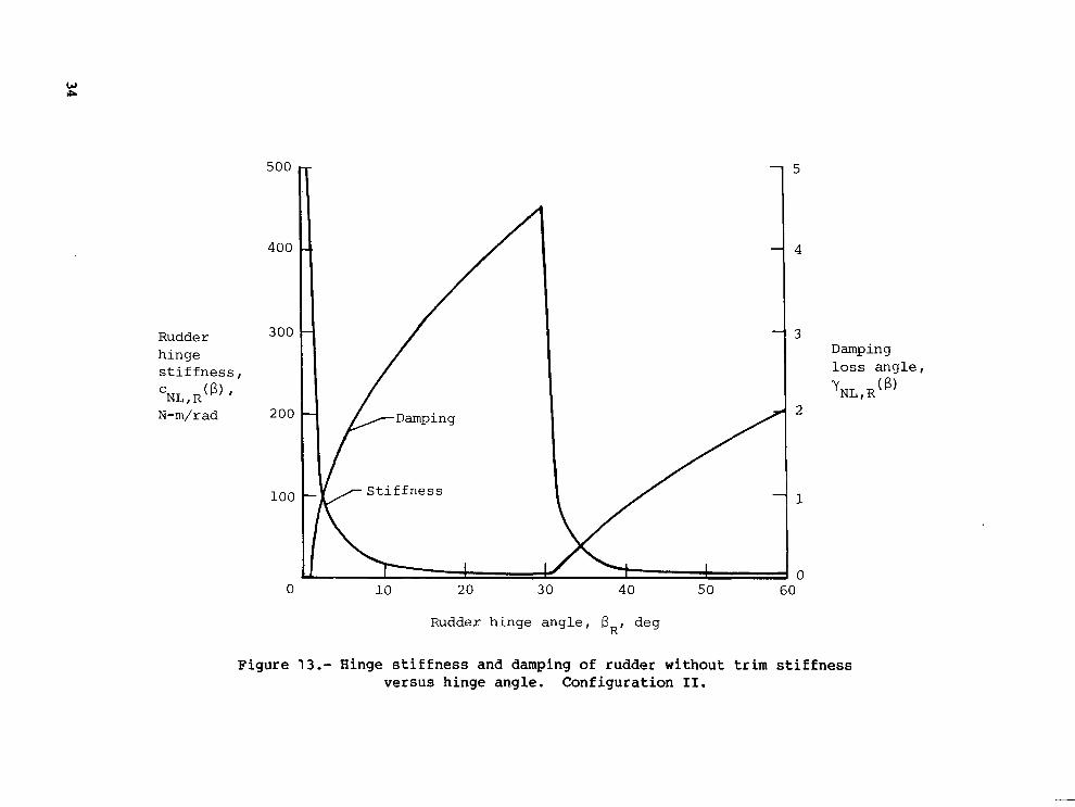
The corresponding equivalent s t i f fness and damping funct ions CNL,R(B) and YNL,R(B) are plotted i n f i g u r e 13. The e q u i v a l e n t a i l e r o n s t i f f n e s s %,A@) can. be c a l c u l a t e d from
The terms M2 , iAf and E are a l ready def ined wi th equat ion (Bl) . Figure 6 shows the resonance frequency f A ( B ) of the aileron system measured as a func- t i o n of B. The e q u i v a l e n t a i l e r o n damping loss angle can be calculated approximately from
and
where
FO,A = 0.283 N-m
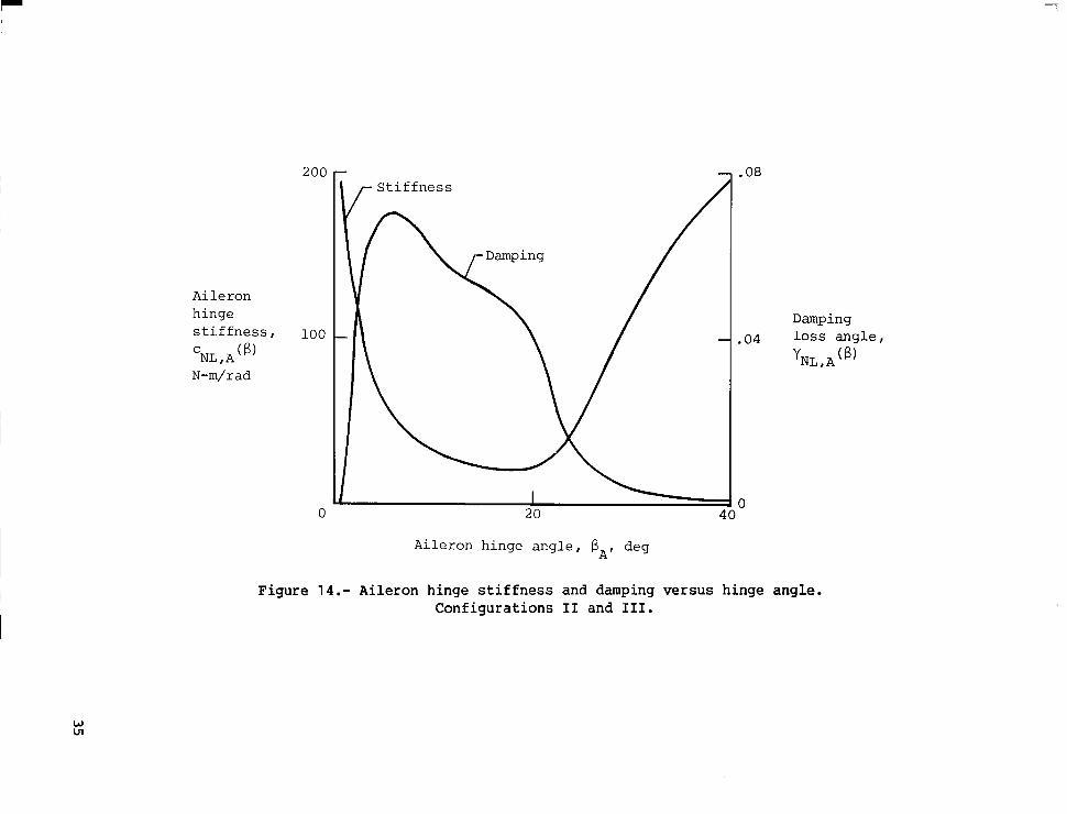
The terms %,A@) and YNL,A(B) are plotted i n f i g u r e 14.
Configurat ion 111
The a i l e r o n c h a r a c t e r i s t i c s of t h i s conf igu ra t ion are equ iva len t to those of conf igu ra t ion 11. I n c o n t r a s t , the rudder characteristics change due to an a d d i t i o n a l trim s t i f f n e s s a t t a c h e d to the rudder peda l mechanism. The equiva- l e n t s t i f f n e s s c a n s i m p l y be c a l c u l a t e d by adding the estimated trim s t i f f n e s s
ct = 33.12 N-drad
to the equ iva len t s t i f fnes s o f con f igu ra t ion 11:
16
APPENDIX B
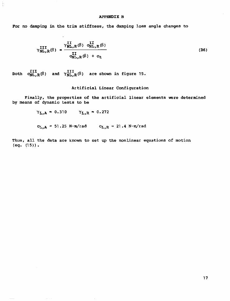
For no damping i n t h e trim s t i f f n e s s , t h e damping loss angle changes to
Both %,R(B) and YNL,R(B) are shown i n f i g u r e 15. I11 I11
A r t i f i c i a l L i n e a r C o n f i g u r a t i o n
F i n a l l y , t h e properties o f t h e a r t i f i c i a l l i nea r e l emen t s were determined by means of dynamic tests to be
YL,A m 0.310 YL,R m 0.272
CL,A = 51.25 N-m/rad CL,R = 21 .4 N-mJrad
Thus, a l l t h e data are known to set up the nonl inear equa t ions of motion (eq. ( 1 5 ) )
17
REFERENCES
1. Breitbach, E.: Effects of Structural Non-Linearities on Aircraft Vibration and Flutter. AGARD-R-665, Jan. 1978.
2. Freymann, Raymond: Bestimmung der dynamischen Aktuatorubertragungsfunk- tionen mit Hilfe eines experimentell-rechnerischen Verfahrens. 2. Flugwiss. Weltraumforsch., Bd. 2, Heft 6, 1978, pp. 405-416.
3. Haidl, G.: Non-Linear Effects in Aircraft Ground and Flight Vibration Tests. AGARD-R-652, Dec. 1976.
4. Sensburg, Otto; and Schoen, Beate: Schwingung- und Flatteranalyse von Flugzeugen mit besonderen nichtlinearen Struktureigenschaften. z. Flugwiss. Weltraumforsch., Bd. 2, Heft 6, 1978, pp. 395-404.
5. Breitbach, E.: Flattersimulation des Flugzeuges mit Hilfe des elektron- ischen Analogrechners unter besonderer Berucksichtigung struktureller Nichtlinearitaten. DLR-FB 73-30, 1973. (Available in English as ESRO TT-121, Dec. 1974.)
6. Breitbach, Elmar J.: Treatment of the Control Mechanisms of Light Airplanes in the Flutter Clearance Process. Science and Technology of Low Speed and Motorless Flight, NASA CP-2085, Pt. 11, 1979, pp. 437-466.
7. Woolston, Donald S.; Runyan, Harry L.; and Andrews, Robert E.: An Investi- gation of Effects of Certain Types of Structural Nonlinearities on Wing and Control Surface Flutter. J. Aero. Sci., vol. 24, no. 1, Jan. 1957, pp. 57-63.
8. Bogoliubov, N. N.; and Mitropolsky, Y. A.: Asymptotic Methods in the Theory of Non-Linear Oscillations. Gordon & Breach Sci. Publ., Inc., 1961.
9. Laurenson, Robert M.; and Trn, Robert M.: Flutter Analysis of Missile Con- trol Surfaces Containing Structural Nonlinearities. A Collection of Technical Papers on Design and Loads - AIAA/ASME/ASCE/AHS 20th Struc- tures, Structural Dynamics, and Materials Conference, Apr. 1979, pp. 352-359. (Available as AIAA Paper 79-0796.)
10. Gelb, Arthur; and Vander Velde, Wallace E.: Multiple-Input Describing Functions and Nonlinear System Design. McGraw-Hill Book Co., c.1968.
11. Iwan, W. D.; and Patula, E. J.: The Merit of Different Error Minimization Criteria in Approximate Analysis. Trans. ASME, Ser. E: J. Appl. Mech., vol. 39, no. 1 , Mar. 1972 , pp. 257-262.
12. Spanos, P-T. D.; and Iwan, W. D.: Harmonic Analysis of Dynamic Systems With Nonsymmetric Nonlinearities. Trans. ASME, Ser. G: J. Dyn. Syst., Meas. , & Control, vol. 101 , no. 1 , Mar. 1979, pp. 31-36.
18

TABLE I.- STRIP SCtIEME AND FIVE ANTISYMMETRICAL NORMAL MODE SEAPES FOR WING
19

TABLE 11.- STRIP SCHEME AND FIVE ANTISYMMETRIC NORMAL M3DE SHAPES FOR ELEVATOR
Strip no. . . . . . . . . . . . 1 2
Width, s, an . . . . . . . . . 7.5 32.5 ..."I_
I I
Half-chord length of elevator, 11, cm . . . . . I 25.75 I 24.5
r = 2
Mode r = 3
Mode r = 4 i I Mode
20
. - "
h, cm . . . . . . . . 0 0
a , rad. . . . . . . . 0 0
h, . . . . . . . . -0.0125 -0.0188 a, rad . . . . . . . . 0.0008 0.0008
h, cm . . . . . . . . 0.0575 0.1725
a, rad . . . . . . . . -0.0005 -0.0009
-
h, . . . . . . . . -0.0238 -0.0125
a , rad. . . . . . . .
-0.0005 0 a, rad. . . . . . . . 0.2495 0.0838 h, cm . . . . . . . .
0 0
0.3581 0.5406 0.7125
-0.0005 -0.0002 -0.0009
-0.0531 1 0.0738 I -0.0863 1 0 0 0
I I
................ ._ . .".". .... .......... ". ... ........ m ..I 111.1 I, I

TABLE 111.- STRIP SCHEME AND FIVE ANTISYMMETRIC NORMAL MDDE SHAPES
S t r i p no . . . . . . . . . . . .
FOR VERTICAL TAIL
~~ ~~~ ~~~~
Width. s f cm . . . . . . . . . .
Half-chord length of ~~ ~~ ~~~
v e r t i c a l tail. R. cm . . . . Rudder chord length
ratio, TR . . . . . . . . . I h . cm . . . . . . . .
Mode I a. rad . . . . . . . . r = l
Mode 1 a. rad . . . . . . . . r = 2
. . . . . . . "
. . . . . . . Mode I a. rad . . . . . . . . r = 3
I B. rad . . . . . . . . I h . cm . . . . . . . .
Mode I a. rad . . . . . . . . r = 4
. . . . . . . .. . . . . . . .
Mode 1 a. rad . . . . . . . . r = 5
I B. rad . . . . . . . .
1
50.64
20
0.443
0.031 3
0.0043
0.1000
-0.0625
0
0
0.2688
0.0025
0
-0.2038
-0.001 8
0.0024
-0.2063
-0.001 7
0.0064
2 3
44.73 37.00
30 40
0.450 0.459
-0.0940 -0.1565
-0.0043
-0.2750 -0.2288
0 0
0.0032 0.0025
0.6063 0.3975
0 0
0 0
-0.11 63 -0.0838
0.1000 0.1000
. -0.01 13 !
-0.001 8
0.0024 0.0024
-0.0025
-0.1325 -0.0250
-0.001 9
0.0064 0.0064
-0.001 9
4 1
28.60 22.10
0.469
-0.0940 -1 . 1 200 -0.0140
0 0 . l O O c i
0.1020
I
-0.1 525
0 0
0 0
-0.1838
0.8563
0 0
0.0085 0.0061 .
1.044
0.3400
-0.0039
0.0040
0.0938
-0.001 2
0.0064
-0.3688
-0.0025
0
0.1212
0.0058
0
21
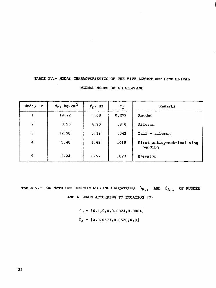
TABLE 1V.- m D A L CHARACTERISTICS OF THE FIVE LOWEST ANTISYMMETRICAL
NORMAL MODES OF A SAILPLANE
Mode, r Remarks Yr fr, Hz Mr, k g - a 2
1
2
Tail - aileron .042 5 .39 12.90 3
Aileron .310 4 .90 3.50
"
19 .22 Rudder 0.272 1 .68
4 First antisymmetrical wing . 01 9 6 .69 15.40 bending
5 Elevator .078 8 .57 3.24 L I I "I
TABLE V.- ROW MATRICES CONTAINING HINGE ROTATIONS B R , ~ AND B A , ~ OF RUDDER
AND AILERON ACCORDING TO EQUATION ( 7 )
22
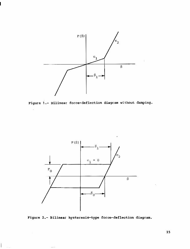
Figure 1.- Bilinear force-deflection diagram without damping.
Figure 2.- Bilinear hysteresis-type force-deflection diagram.
23
.3
. L
- E
B l l A 2
.I
J 0 5 10 1 5 2 0 2 5
230
220
Speed V I km/hr
210
202
Figure 3.- Some characteristic functions near matching point. Configuration 11; r l ~ O / B 1 ,R = 0.858.

2
1
rl; - rlA 0
'1,A 0
-1
-2
0 2 4 8 10
240
220
210
Speed, V, km/hr
200
190
180
Figure 4.- Functions ( Q A ~ - ~ ~ O ) / f 3 1 ,A and V versus nAo for special case of three different matching points. Configuration 111; n ~ O / f 3 1 , ~ = 0.5.
1.5 -
1.0 -
. 5 "
A i l e ron h inge moment I
F (8,) I N-m
- 3 . 0 -20 -10 0 10 20
Ai le ron h inge angle I f iA1 deg
Figure 5.- Measured force-deflection diagram of aileron system for two different amplitudes. Antisymmetrical case.
26

I
1 c
A i l e r o n resonance frequency, f A ( B ) I Hz
0 1 0 20
Ai l e ron h inge ang le , B A I deg
Figure 6.- Measured resonance frequency of antisymmetrical aileron vibration versus hinge angle.
27
t -50 - 2 5 0 25 5 0
Rudder hinge angle , 8,, deg
Figure 7.- Measured force-deflection diagram of rudder system with trim stiffness removed.
28

1.1
1.(
rlF
Bl
t ._
c 120
Aileron-- /
S tab le
Unstable
160 200
Speed, V I km/hr
Figure 8.- Nonlinear flutter boundary for configuration I.
240
29

1.5
1.0
. 5
0 1 2 0
S t a b l e
Uns tab le
160 200
Speed, V I km/hr
Figure 9.- Nonlinear flutter boundary for configuration 11.
240
30

1.5
1.0
- 5
120 . .
Stable
160 20G
Speed, V , km/hr
Figure 10.- Nonlinear flutter boundary for configuration 111.
31

I 11111 111 I
/Rudder ac tua t ing fo rce
1-
-
, G/ Midstr ip sec t ion
Aileron actuat ing force
/
7 g 1 0 8 1 2 4 3
I r I
- s -
L A
' 2 3 4 5
= - A 2 k
Y 2 k " q Section A - A
Figure 11.- Schematic view of a sailplane.
32

Hinge s t i f f n e s s , c (6) I NL N-m
500
400
300
200
100
- YNL , R YNL , A
- = o
- HC 0
0 0
/ 0
-
A i l e ron
- /
"""" /' I I I 10 20 3 0 40
Hinge angle I 6, deg
Figure 12.-'Hinge stiffness of rudder and aileron versus hinge angle. Configuration I.
50 60
33
W rp
500
400
Rudder hinge s t i f f n e s s ,
300
( B ) J NL,R N-m/rad 200
100
0 10 20 30 40
Rudder hinge angle, BR, deg
50
5
4
3 Damping loss a n g l e ,
YNL, R (8 , 2
1
0
Figure 13.- Hinge stiffness and damping of rudder without trim stiffness versus hinge angle. Configuration 11.
200
Aileron hinge s t i f f n e s s , 100 c ( B ) NL ,A N-m/rad
0
- S t i f f n e s s
20
08
a o 40
Damping 04 loss angle ,
YNL , A (6)
Aileron hinge angle , PA, deg
Figure 14.- Aileron hinge stiffness and damping versus hinge angle. Configurations I1 and 111.
W vl

W m
600
500
400
Rudder hinge s t i f f n e s s , c (6, I 30C
N L , R N-m/rad
20c
1.2
1.0
.8
Damping loss angle ,
. 4
. 2
0 0 10 20 30 40 50 60
Rudder hinge angle, BR, deg
Figure 15.- Hinge stiffness and damping of rudder with trim stiffness versus hinge angle. Configuration 111.

1. Report No. 2. Government Accession No. 3. Recipient's Catalog No.
NASA TP-1620 1 4. Title and Subtitle
. .. .
5. Report Date FLUTTER ANALYSIS OF AN AIRPLANE WITH MULTIPLE May 1980 STRUCTURAL NNLINEARITIES I N THE CONTROL SYSTEM I
6. Performing Organization Code
7. Author(s1 0. Performing Organization Report No.
Elmar J. B r e i t b a c h L-13356 10. Work Unit No.
9. Performing Organization Name and Address 505-33-53-01 NASA Langley Research Center Hampton, K4 23665 11. Contract or Grant No.
13. Type of Repor t and Period Covered
2. Sponsoring Agency Name and Address T e c h n i c a l Paper Nat iona l Aeronaut ics and Space A d m i n i s t r a t i o n Washington, DC 20546 14. Sponsoring Agency Code
5. pplementary N0te.s ~~
E%ar J. Bre l tbach: NRC-NASA Sen io r Res iden t Resea rch Associate, now a t DEVLR, I n s t i t u t f;;r Aeroelastik, G o t t i n g e n , West Germany.
6. Abstract
Experience has shown t h a t t h e f l u t t e r p r e d i c t i o n process f o r a i r p l a n e s c a n be r r e a t l y a f f e c t e d by s t r o n g c o n c e n t r a t e d n o n l i n e a r i t i e s which may b e l o c a l i z e d i n fie l ink ing e l emen t s of t h e c o n t r o l mechanism, i n t h e p i v o t j o i n t s of v a r i a b l e - sweep-wing systems, and in the connect ing points between wing- and pylon-mounted x t e r n a l stores. The p r i n c i p l e of e q u i v a l e n t l i n e a r i z a t i o n o f f e r s a n e f f i c i e n t ) o s s i b i l i t y for s o l v i n g t h e related n o n l i n e a r f l u t t e r e q u a t i o n s i n t h e f r e q u e n c y lomain as a complement to t h e well-known time danain procedures . Taking as an !xample an a i r p l a n e w i t h n o n l i n e a r c o n t r o l c h a r a c t e r i s t i c s , it is demonstrated LOW t h e e q u i v a l e n t l i n e a r i z a t i o n a p p r o a c h c a n be extended to r a t h e r c o m p l i c a t e d ;y s t ems w i th mu l t ip l e sets of s t r o n g l y i n t e r a c t i n g , c o n c e n t r a t e d n o n l i n e a r i t i e s .
17. Key Words (Suggested by Author(s1) 18. Distribution Statement ~~ - . .
F l u t t e r Nonl inear
U n c l a s s i f i e d - Unlimited
Con t r o l
Subject Category 08 ~ -
21. NO. of Pages 22. Rice'
For sale by the National Technical Information Service, Sprlnefield. Vlrglnla 22161 NASA-Lang1 ey , 1980

National Aeronautics and THIRD-CLASS BULK RATE Space Administration
Washington, D.C.' 20546
Postage and Fees Paid National Aeronautics and Space Administration NASA451
Official Business
Penalty for Private Use, $300
, . POSTMASTER: If Undeliverable (Section 158 Postal Manual) Do Not Return