Airplane Wing Flutter Boundary Optimization Using Coupled...
8
AASCIT Communications Volume 2, Issue 4 June 20, 2015 online ISSN: 2375-3803 Airplane Wing Flutter Boundary Optimization Using Coupled Solver Simulations J. Bruce Ralphin Rose Department of Aeronautical Engineering, Regional centre of Anna University, Tirunelveli, India R. Allocious Britto Rajkumar Department of Aeronautical Engineering, Regional centre of Anna University, Tirunelveli, India Keywords Flutter Speed, Finite Element Analysis, Computational Fluid Dynamics, CFD-CSD Coupling, Numerical Discretization n the cruising flight regime, an aircraft wing experiences severe aerodynamic forces from all directions and above the critical speeds it initializes the flutter. Flutter phenomenon is a catastrophic one that leads to temporal (or) permanent failure of airplane structural components. To delay the flutter speed boundary or occurrences, a variety of methods have been suggested by many aeroelasticians in the past few decades. This article involves in the flutter boundary optimization using coupled solver simulations especially bending-torsion flutter. Coupling is produced by combining the Computational Fluid Dynamics (CFD) solutions and Computational Structural Dynamics (CSD) solutions with the help of a system coupling through FEA procedure. Initially, it is used to predict the flutter speed of conventional airplane wing configuration and then the analysis is extended to optimize the flutter speed through various material based properties. In specific, the relation among stresses produced on the wing is considered and it is customized to reduce the forced vibration frequency for expanding the flutter boundary. Then, the wing model is aerodynamically optimized with the help of force computations, frequencies and material properties. Numerical results are presented and verified with theoretical calculations to prove the feasibility of present methodology. This iterative design process can be revised again and again until the flutter speed boundary is converged to the optimum velocities. Introduction Flutter is an unstable oscillation that leads to destructive dynamic vibrations to the airframes. Flutter occurs on surfaces of the aircraft, such as the wing, the horizontal stabilizer, as well as on control surfaces like aileron or the elevator for instance. Philippe Geuzaine et al. (2003) have reported that non-linear aero-elastic simulation technology, and perhaps other similar ones, are capable of computing in the inviscid case five flutter point solutions for a fighter in the transonic regime. They are using three field methodology method [1] in which structural equations are formulated with material coordinates and fluid equations are formulated by spatial coordinates then they are coupled with the help of Arbitrary Lagrangian Eularian method. XIE Chang Chuan et al. [2] (2012) has confirmed that the combination of lifting line method for curved high aspect ratio wing is accurate one for aeroelastic tests. They have conducted different tests like mode test, flutter test, deformation test on wing model. In conclusion, the article states that, for high aspect ratio wings, the amplitude of Limit Cycle Oscillation (LCO) is gradually growing when the system losses its stability. Zhang Jian et al. (2009) have produced MATLAB coding for the analysis of high aspect ratio flexible wings. The effects of structural non-linearity on the flight speed and drag component of an airplane is presented with detailed characteristic curves by their numerical coding techniques. [3] After few numerical simulations, it is concluded that as flight speed is relatively high and stall occurs, dynamic stall dominates the LCO behavior. [4] Giulio Romanelli et al. (2012) have used MBDyn for structural application and Aerofoam for aerodynamical application. [5] They focused on F-18 High alpha research vehicle. For the experimental purposes, they are using Benchmark Active Control Technology (BACT). [6] Its objective is to compare the low fidelity model to high fidelity BACT model. The main disadvantage of Aerofoam is, it has no density based on 2008 version. Kwan-Hwa Byun et al. (2006) has selected the F-16 aircraft for their CFD analysis and performance optimization research purposes. [7] Flutter occurs because of the wings absorbing energy from the moving airstream. I
Transcript of Airplane Wing Flutter Boundary Optimization Using Coupled...
AASCIT Communications
Volume 2, Issue 4
June 20, 2015 online
ISSN: 2375-3803
Airplane Wing Flutter Boundary Optimization Using
Coupled Solver Simulations
J. Bruce Ralphin Rose Department of Aeronautical Engineering, Regional centre of Anna University, Tirunelveli, India
R. Allocious Britto Rajkumar Department of Aeronautical Engineering, Regional centre of Anna University, Tirunelveli, India
Keywords
Flutter Speed, Finite Element Analysis, Computational Fluid Dynamics, CFD-CSD Coupling, Numerical Discretization
n the cruising flight regime, an aircraft wing experiences severe aerodynamic forces from all directions and above the
critical speeds it initializes the flutter. Flutter phenomenon is a catastrophic one that leads to temporal (or) permanent
failure of airplane structural components. To delay the flutter speed boundary or occurrences, a variety of methods have been
suggested by many aeroelasticians in the past few decades. This article involves in the flutter boundary optimization using
coupled solver simulations especially bending-torsion flutter. Coupling is produced by combining the Computational Fluid
Dynamics (CFD) solutions and Computational Structural Dynamics (CSD) solutions with the help of a system coupling
through FEA procedure. Initially, it is used to predict the flutter speed of conventional airplane wing configuration and then the
analysis is extended to optimize the flutter speed through various material based properties. In specific, the relation among
stresses produced on the wing is considered and it is customized to reduce the forced vibration frequency for expanding the
flutter boundary. Then, the wing model is aerodynamically optimized with the help of force computations, frequencies and
material properties. Numerical results are presented and verified with theoretical calculations to prove the feasibility of present
methodology. This iterative design process can be revised again and again until the flutter speed boundary is converged to the
optimum velocities.
Introduction
Flutter is an unstable oscillation that leads to destructive dynamic vibrations to the airframes. Flutter occurs on surfaces of
the aircraft, such as the wing, the horizontal stabilizer, as well as on control surfaces like aileron or the elevator for instance.
Philippe Geuzaine et al. (2003) have reported that non-linear aero-elastic simulation technology, and perhaps other similar ones,
are capable of computing in the inviscid case five flutter point solutions for a fighter in the transonic regime. They are using
three field methodology method [1]
in which structural equations are formulated with material coordinates and fluid equations
are formulated by spatial coordinates then they are coupled with the help of Arbitrary Lagrangian Eularian method.
XIE Chang Chuan et al. [2]
(2012) has confirmed that the combination of lifting line method for curved high aspect ratio wing is
accurate one for aeroelastic tests. They have conducted different tests like mode test, flutter test, deformation test on wing model.
In conclusion, the article states that, for high aspect ratio wings, the amplitude of Limit Cycle Oscillation (LCO) is gradually
growing when the system losses its stability. Zhang Jian et al. (2009) have produced MATLAB coding for the analysis of high
aspect ratio flexible wings. The effects of structural non-linearity on the flight speed and drag component of an airplane is
presented with detailed characteristic curves by their numerical coding techniques. [3]
After few numerical simulations, it is
concluded that as flight speed is relatively high and stall occurs, dynamic stall dominates the LCO behavior. [4]
Giulio Romanelli
et al. (2012) have used MBDyn for structural application and Aerofoam for aerodynamical application. [5]
They focused on F-18
High alpha research vehicle. For the experimental purposes, they are using Benchmark Active Control Technology (BACT). [6]
Its
objective is to compare the low fidelity model to high fidelity BACT model. The main disadvantage of Aerofoam is, it has no
density based on 2008 version. Kwan-Hwa Byun et al. (2006) has selected the F-16 aircraft for their CFD analysis and
performance optimization research purposes. [7]
Flutter occurs because of the wings absorbing energy from the moving airstream.
I
ISSN: 2375-3803 145
In the classical bending torsion flutter, the phase difference between the bending and the torsional motions lead to flutter [8]
. T.
K. Pradeepa et al. (2012) has studied about transonic flutter, shocks, and transonic dips and found the best mechanisms and
techniques for flutter effects.
Yamaguchi et al. [9] [10]
and Watanabe et al. [11] [12]
conducted a large number of experiments to determine the factors
influencing the critical flutter velocity. Jesse McCarthy and their colleagues have done research on flow-induced flutter of
slender cantilever high-compliance plates. [13]
They used experimental method to produce some finer and direct results. The
analyzing procedure for flutter is well established by the means of experimental tests and computational simulations from
various aeroelastic studies. From the core review on aeroelasticity, this article is proposed a flutter boundary extension analysis
with flutter prevention techniques at low flight speeds.
Materials and Modeling
Materials
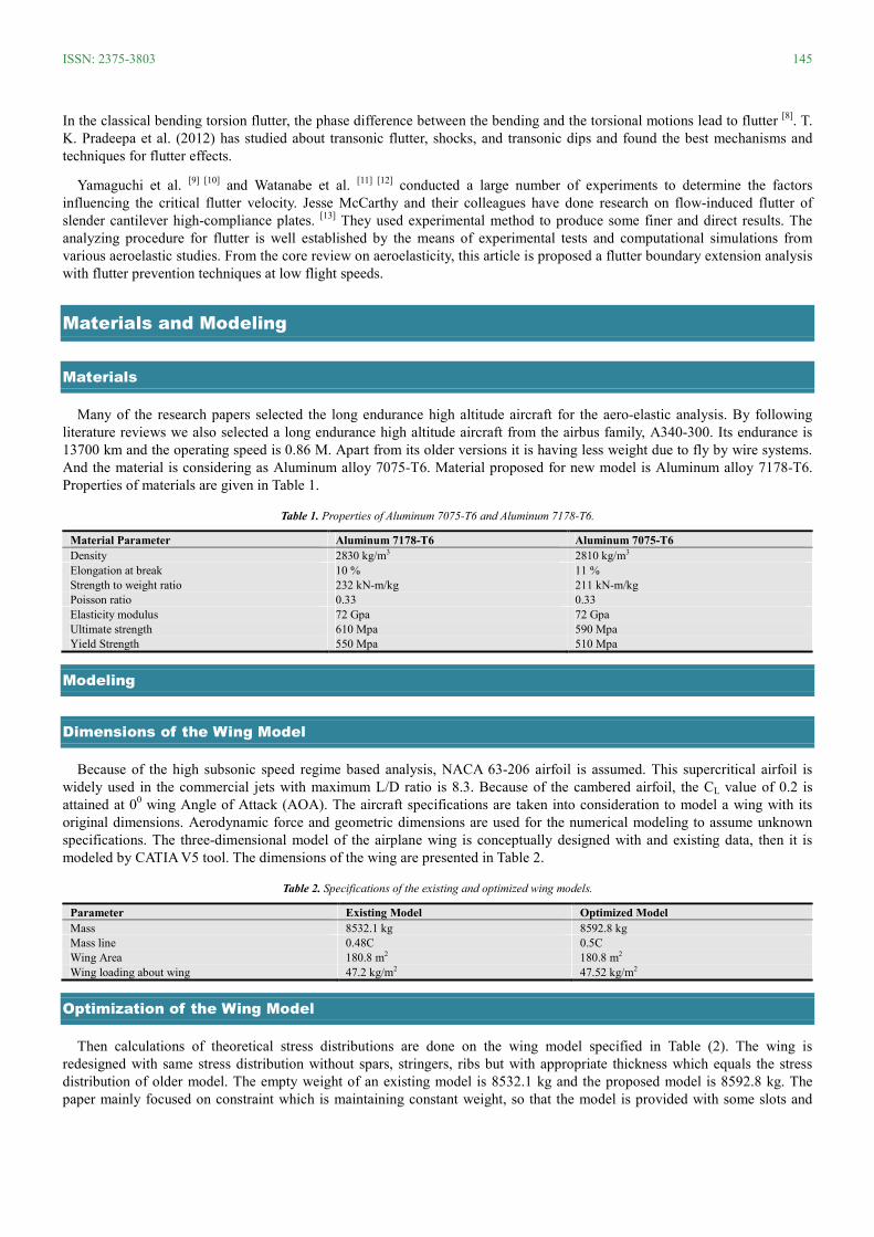
Many of the research papers selected the long endurance high altitude aircraft for the aero-elastic analysis. By following
literature reviews we also selected a long endurance high altitude aircraft from the airbus family, A340-300. Its endurance is
13700 km and the operating speed is 0.86 M. Apart from its older versions it is having less weight due to fly by wire systems.
And the material is considering as Aluminum alloy 7075-T6. Material proposed for new model is Aluminum alloy 7178-T6.
Properties of materials are given in Table 1.
Table 1. Properties of Aluminum 7075-T6 and Aluminum 7178-T6.
Material Parameter Aluminum 7178-T6 Aluminum 7075-T6
Density 2830 kg/m3 2810 kg/m3
Elongation at break 10 % 11 %
Strength to weight ratio 232 kN-m/kg 211 kN-m/kg
Poisson ratio 0.33 0.33
Elasticity modulus 72 Gpa 72 Gpa
Ultimate strength 610 Mpa 590 Mpa
Yield Strength 550 Mpa 510 Mpa
Modeling
Dimensions of the Wing Model
Because of the high subsonic speed regime based analysis, NACA 63-206 airfoil is assumed. This supercritical airfoil is
widely used in the commercial jets with maximum L/D ratio is 8.3. Because of the cambered airfoil, the CL value of 0.2 is
attained at 00 wing Angle of Attack (AOA). The aircraft specifications are taken into consideration to model a wing with its
original dimensions. Aerodynamic force and geometric dimensions are used for the numerical modeling to assume unknown
specifications. The three-dimensional model of the airplane wing is conceptually designed with and existing data, then it is
modeled by CATIA V5 tool. The dimensions of the wing are presented in Table 2.
Table 2. Specifications of the existing and optimized wing models.
Parameter Existing Model Optimized Model
Mass 8532.1 kg 8592.8 kg
Mass line 0.48C 0.5C
Wing Area 180.8 m2 180.8 m2
Wing loading about wing 47.2 kg/m2 47.52 kg/m2
Optimization of the Wing Model
Then calculations of theoretical stress distributions are done on the wing model specified in Table (2). The wing is
redesigned with same stress distribution without spars, stringers, ribs but with appropriate thickness which equals the stress
distribution of older model. The empty weight of an existing model is 8532.1 kg and the proposed model is 8592.8 kg. The
paper mainly focused on constraint which is maintaining constant weight, so that the model is provided with some slots and
146 2015; 2(4): 144-151
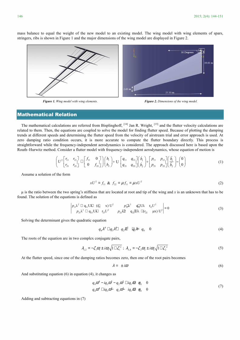
mass balance to equal the weight of the new model to an existing model. The wing model with wing elements of spars,
stringers, ribs is shown in Figure 1 and the major dimensions of the wing model are displayed in Figure 2.
Figure 1. Wing model with wing elements. Figure 2. Dimensions of the wing model.
Mathematical Relation
The mathematical calculations are referred from Bisplinghoff, [14]
Jan R. Wright, [15]
and the flutter velocity calculations are
related to them. Then, the equations are coupled to solve the model for finding flutter speed. Because of plotting the damping
trends at different speeds and determining the flutter speed from the velocity of airstream trial and error approach is used. At
zero damping ratio condition occurs, it is more accurate to compute the flutter boundary directly. This process is
straightforward while the frequency-independent aerodynamics is considered. The approach discussed here is based upon the
Routh–Hurwitz method. Consider a flutter model with frequency-independent aerodynamics, whose equation of motion is
11 12 112
21 22 22
0
0
r r fU
r r f
+
1
2
b
b
+ U 11 12 1
2 21 22
q q b
q q b
ɺ
ɺ+
1
2
11 12
21 22
p p
p p
b
b
ɺɺ
ɺɺ=
0
0
(1)
Assume a solution of the form
2
11xU f= & 2
22 11f f xUµ µ= = (2)
µ is the ratio between the two spring’s stiffness that are located at root and tip of the wing and x is an unknown that has to be
found. The solution of the equations is defined as
2 2 2 2
11 11 11 12 12 12
2 2 2
21 21 21 22 22 22
λ q Uλ ( x) U λ q Uλ r0
λ q Uλ r λ2 q Uλ ( µx) U
p r p U
p U p r
+ + + + +=
+ + + + + (3)
Solving the determinant gives the quadratic equation
4 3 2
4 3 2 1 0 0q q q q qλ λ λ λ+ + + + = (4)
The roots of the equation are in two complex conjugate pairs,
2
1,2 1 1 1 11iλ ζ ω ω ζ= − ± + ; 2
3,4 2 2 2 21iλ ζ ω ω ζ= − ± + (5)
At the flutter speed, since one of the damping ratios becomes zero, then one of the root pairs becomes
iλ ω= ± (6)
And substituting equation (6) in equation (4), it changes as
4 3 2
4 3 2 1 0
4 3 2
4 3 2 1 0
0
0
q iq q iq q
q iq q iq q
ω ω ω ωω ω ω ω
− − + + =
+ − − + = (7)
Adding and subtracting equations in (7)
ISSN: 2375-3803 147
4 2 3
4 2 0 3 10 0?q q q and iq iqω ω ω ω− + = − = (8)
Frequency at the flutter condition is given by, 1 3/ω = q q (9)
Equation (9) can be substituted into the quadratic part of equation (8) to give an expression,
2 2
4 1 1 2 3 0 3 0q q q q q q q− + = (10)
The flutter speed is obtained since the parameters in the equation are known functions of V. The same result can be obtained
by considering the Routh–Hurwitz stability criteria for the quartic equation (4), leading to the condition for stability,
2 2
1 2 3 4 1 0 3 0q q q q q q q− − > (11)
Knowing the matrix terms, it is possible to determine directly the critical flutter speeds of a flutter model using the following
procedure. Expanding the Equation (1) gives the fourth-order characteristic polynomial, where
2
2 1 0( )q x aa U= + , 3 11 22 11 22 21 12 12 21( )q q q p p q pp Uq= + − − , 4 11 22 21 12
q p p p p= − , 3
1 1 0( )b x bb U= +
2 4
0 2 1 0( )b x c xc c U= + + (12)
Substituting Equations (12) into expression (10) for the critical condition and eliminating a factor of U6, gives a quadratic
equation in terms of the unknown x such that
2 2 2 2
4 1 3 1 1 3 2 4 1 0 3 0 1 3 1 2 3 12( ) ( )b q b a q c x q b q q b a q b a cq q x− + + − − + 2 2
4 0 3 0 2 3 0 0( )b q a qq b c+ − + = (13)
The two roots of equation (13) are then put into Equation (2), giving the two critical flutter speeds between which the system
is unstable. Obviously the lowest speed is the one that is of interest, since any aircraft will probably have been destroyed long
before the second critical condition has been reached.
Numerical Simulation
Fluid Structural Interaction (FSI)
Fluid–structure interaction (FSI) problems are too complex to solve by analytical methods and consequently it should be
analyzed by means of experiments or numerical simulations. In this article, the series of events to approach the flutter
boundary optimization problem can be stated in a few steps as follows. At first, the flutter speed of the model is calculated
from the empirical relations as well as from previous studies. Then, the model is subjected to various aerodynamic simulations
at different air speeds to determine the respective flow induced stress values on the wing structure. Then the frequencies for the
model are predicted using FSI-modal coupling process. [17]
After obtaining the frequencies, the model is redesigned with major
considerations like mass balancing, change of flexural line, change of material and mass distribution line. In the presence of all
these changes, the model is subjected to same air speeds to determine the frequency and stress distributions on the optimized
wing. Thus, the relation between stress and variable airspeed (flutter) is computed to optimize the flutter boundary.
Discretization
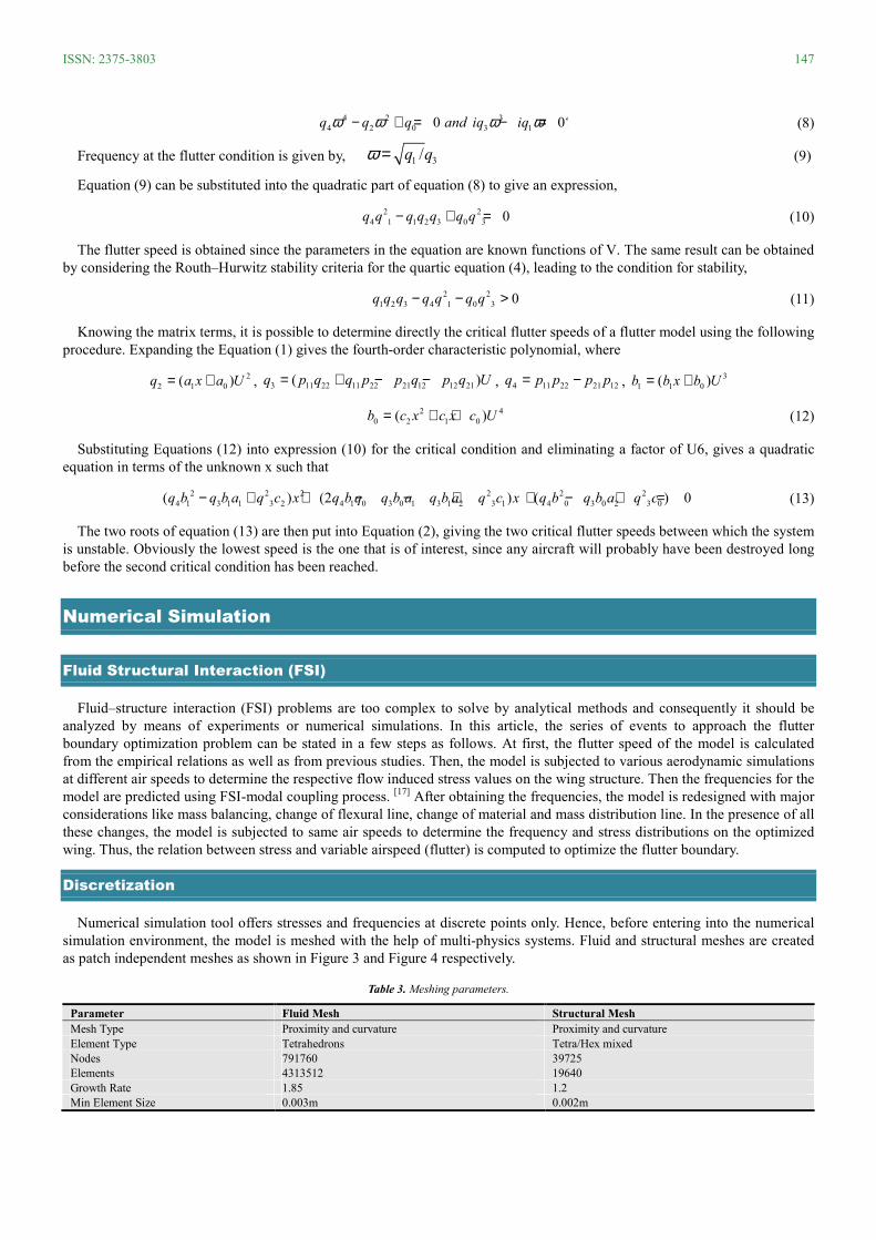
Numerical simulation tool offers stresses and frequencies at discrete points only. Hence, before entering into the numerical
simulation environment, the model is meshed with the help of multi-physics systems. Fluid and structural meshes are created
as patch independent meshes as shown in Figure 3 and Figure 4 respectively.
Table 3. Meshing parameters.
Parameter Fluid Mesh Structural Mesh
Mesh Type Proximity and curvature Proximity and curvature
Element Type Tetrahedrons Tetra/Hex mixed
Nodes 791760 39725
Elements 4313512 19640
Growth Rate 1.85 1.2
Min Element Size 0.003m 0.002m
148 2015; 2(4): 144-151
Figure 3. Fluid mesh (Wing on a fluid domain). Figure 4. Structural mesh.
The tetrahedron mesh element is used for both the type of meshes because of its accuracy on discretization of curved
boundaries. At first, for the flow analysis the structural part is suppressed for fluid meshing and for structural analysis the
process is vice versa. The meshing parameters are compared between fluid and structural mesh as shown in Table 3. Then the
boundary conditions that are derived from theoretical flutter computations are assigned to the models. The flutter velocity for
the model is given as 102.37 m/s. All other typical boundary conditions are given in Table 4.
Table 4. Boundary conditions.
Parameter Existing Model & Optimized Model
Reference flutter velocity (UR) 56.77 m/s
Theoretical flutter velocity (UR) 102.37 m/s
Experimental flutter velocity (UR) 89.55 m/s
Density of air (ρ) 0.413 kg/m3
Pressure (P) 26.426 KPa
Velocity of sound (a) 299.34 m/s
Viscosity of air (µ) 1.46E-5 kg/m/s
The relaxation factor for the convergence criteria in a fluent analysis is set to 1xE-6
for better results. If the convergence
criterion is very small the solution converging time is very high but the accuracy of the results also increases to peak values.
Results and Comparison
Structural Data Output
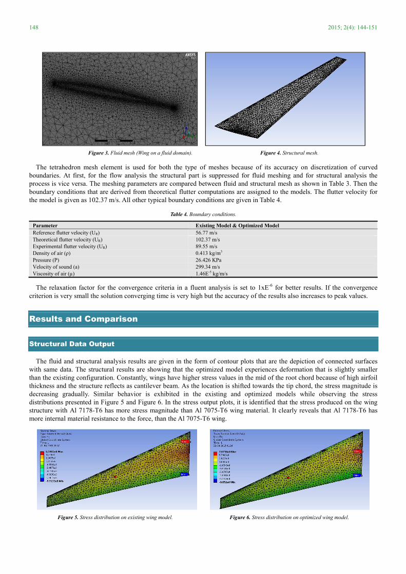
The fluid and structural analysis results are given in the form of contour plots that are the depiction of connected surfaces
with same data. The structural results are showing that the optimized model experiences deformation that is slightly smaller
than the existing configuration. Constantly, wings have higher stress values in the mid of the root chord because of high airfoil
thickness and the structure reflects as cantilever beam. As the location is shifted towards the tip chord, the stress magnitude is
decreasing gradually. Similar behavior is exhibited in the existing and optimized models while observing the stress
distributions presented in Figure 5 and Figure 6. In the stress output plots, it is identified that the stress produced on the wing
structure with Al 7178-T6 has more stress magnitude than Al 7075-T6 wing material. It clearly reveals that Al 7178-T6 has
more internal material resistance to the force, than the Al 7075-T6 wing.
Figure 5. Stress distribution on existing wing model. Figure 6. Stress distribution on optimized wing model.
ISSN: 2375-3803 149
Frequency Output
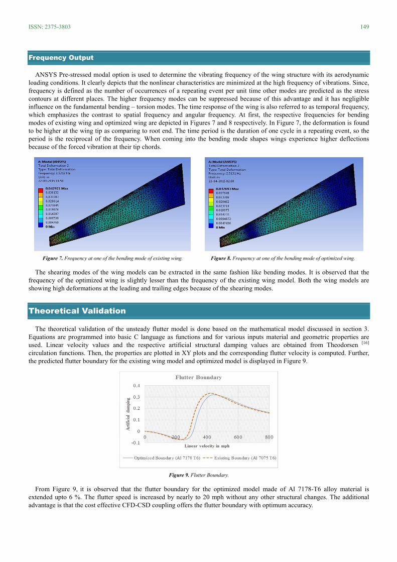
ANSYS Pre-stressed modal option is used to determine the vibrating frequency of the wing structure with its aerodynamic
loading conditions. It clearly depicts that the nonlinear characteristics are minimized at the high frequency of vibrations. Since,
frequency is defined as the number of occurrences of a repeating event per unit time other modes are predicted as the stress
contours at different places. The higher frequency modes can be suppressed because of this advantage and it has negligible
influence on the fundamental bending – torsion modes. The time response of the wing is also referred to as temporal frequency,
which emphasizes the contrast to spatial frequency and angular frequency. At first, the respective frequencies for bending
modes of existing wing and optimized wing are depicted in Figures 7 and 8 respectively. In Figure 7, the deformation is found
to be higher at the wing tip as comparing to root end. The time period is the duration of one cycle in a repeating event, so the
period is the reciprocal of the frequency. When coming into the bending mode shapes wings experience higher deflections
because of the forced vibration at their tip chords.
Figure 7. Frequency at one of the bending mode of existing wing. Figure 8. Frequency at one of the bending mode of optimized wing.
The shearing modes of the wing models can be extracted in the same fashion like bending modes. It is observed that the
frequency of the optimized wing is slightly lesser than the frequency of the existing wing model. Both the wing models are
showing high deformations at the leading and trailing edges because of the shearing modes.
Theoretical Validation
The theoretical validation of the unsteady flutter model is done based on the mathematical model discussed in section 3.
Equations are programmed into basic C language as functions and for various inputs material and geometric properties are
used. Linear velocity values and the respective artificial structural damping values are obtained from Theodorsen [16]
circulation functions. Then, the properties are plotted in XY plots and the corresponding flutter velocity is computed. Further,
the predicted flutter boundary for the existing wing model and optimized model is displayed in Figure 9.
Figure 9. Flutter Boundary.
From Figure 9, it is observed that the flutter boundary for the optimized model made of Al 7178-T6 alloy material is
extended upto 6 %. The flutter speed is increased by nearly to 20 mph without any other structural changes. The additional
advantage is that the cost effective CFD-CSD coupling offers the flutter boundary with optimum accuracy.
150 2015; 2(4): 144-151
Conclusions
An existing wing and optimized wing are analyzed for the flutter frequency at flutter velocity conditions. The wing
structural optimization is done by mass balancing and material replacement. The optimized model is having higher stress value
which is used to withstand such an applied flutter velocity over than existing model. The optimized model with the material Al
7178-T6 possesses slightly low vibrating frequency than the wing with Al 7075- T6 alloy. As the low frequency mode is taken
into account nonlinear effects are playing a vital role on it. Then, the theoretical validation is done to check the flutter
velocities both models then the boundary of flutter is depicted. When frequency is less, effects of non-linearity also less which
delays flutter velocity and enlarge the flutter boundary. By the positive results from the numerical analysis, the new optimized
model with Al 7178-T6 is proposed to delay the flutter phenomena on an airplane wing.�
J. Bruce Ralphin Rose
Dr. J. Bruce Ralphin Rose is presently working as an Assistant Professor in the Department of
Aeronautical Engineering at Anna University - Regional Centre, Tirunelveli, India. He received his
B.E and M.E degrees with First Class & Distinction in the field of Aeronautical Engineering from
Anna University, Chennai, India. He is also received his Ph.D. degree in the field of Aeroelasticity
from Anna University, Chennai during October 2014. He has published more than 25 reputed Journal
articles in the recent years in the field of active aeroelastic control. His research areas include Aircraft
structural optimization, aeroelastic tailoring with advanced composites and metals, and Aircraft design.
The goal of his research work is to develop efficient computational tools for integrated synthesis of
actively-controlled Aircraft. Dr. Bruce Ralphin Rose’s research has been supported by the Anna
University, Chennai and Defense Research and Development Organization (DRDO), India.
Email address: [email protected]
R. Allocious Britto Rajkumar
Allocious Britto Rajkumar. R, who revels in the new innovative and initiative methods to approach
Fluid Structural Interaction (FSI) problems in connection to Aircraft structures and Aerodynamics.
Flutter occurred on an airplane structural components made him more scintillation and research
interest, Hence to deeper his understanding and knowledge in the field of Aeroelasticity, he is pursuing
his Master degree in the field of Aeronautical Engineering at the Anna University, Chennai, India. He
also awarded a Bachelor degree in the field of Aeronautical Engineering in during the month of May
2012 by the Anna University, Chennai, India. His current research work is “Optimization techniques to
delay flutter” and it will give reasonable remedies to delay flutter phenomenon.
Email address: [email protected]
References
[1] Philippe Geuzaine, Gregory Brown, Chuck Harris, and Charbel Farhat. “Aeroelastic Dynamic Analysis of a Full F-16 Configuration for Various Flight Conditions”. AIAA JOURNAL Vol. 41, No. 3, March 2003
[2] XIE ChangChuan, LIU Yi & YANG Chao , “Theoretic analysis and experiment on aeroelasticity of very flexible wing”, science china journal(2012), Vol.55 No.9: 2489–2500
[3] Jinwu Xiang, Yongju Yan, Daochun Li, Recent advance in nonlinear aeroelastic analysis and control of the aircraft, Chinese Journal of Aeronautics, Volume 27, Issue 1, February 2014, Pages 12–22
[4] R. M. Bennet and J.W. Edwards, “An overview of recent developments in computational aeroelasticity”, Proceedings of the 29th AIAA Fluid Dynamics Conference, 1998.
[5] Giulio Romanelli , Tommaso Solcia , “Design and verification of flutter suppression control systems by multidisciplinary co-simulations”, 28th International congress of the aeronautical sciences,2012.
[6] M. R. Waszak, “Modeling the benchmark active control technology wind tunnel model for application to flutter suppression”, AIAA Technical Paper 3437, 1996.
[7] Kwan-Hwa Byun, Seung-Moon Jun,”Flutter analysis of f-16 aircraft utilizing test modal data”, 25th International congress of the aeronautical sciences.2006.
[8] K.H.Byun, C.Y.Park, J.H Kim. Ground Vibration Test on KF-16D. Journal of KSASS, Vol. 33, No.5, pp41-49, 2005.
ISSN: 2375-3803 151
[9] Yamaguchi N, Sekiguchi T, Yokota K, and Tsujimoto Y. “Flutter limits and behavior of a flexible thin sheet in high-speed flow—I: analytical method for prediction of the sheet behavior”. ASME Journal of Fluids Engineering. Vol. No. 122, pp 65–73, 2000.
[10] Shubov MA, ‘On fluttering modes for aircraft wing model in subsonic air flow’. Proc Math Phys Eng Sci. 2014 Dec 8;470(2172):20140582.
[11] Watanabe Y, Isogai K, Suzuki S, and Sugihara M.”A theoretical study of paper flutter”, Journal of Fluids and Structures. Vol. No. 16 (4), pp 543–560, 2002.
[12] Watanabe Y, Suzuki S, Sugihara M, and Sueoka Y. “An experimental study of paper flutter”, Journal of Fluids and Structures. Vol No. 16 (4), pp 529–542, 2002.
[13] Arvind Deivasigamani, Jesse McCarthy, Simon Watkins, Sabu John, Floreana Coman,”Flow-induced flutter of slender cantilever high-compliance plates”, 28th International congress of the aeronautical sciences, 2012.
[14] Bisplinghoff, R.L., Ashley, H. and Halfman, H., Aeroelasticity. Dover Science, 1996, ISBN 0-486-69189-6, pgs 604-632;
[15] Tuzcu, I. and Nguyen, N. (2014). "Flutter of Maneuvering Aircraft", J. Aerosp. Eng, ASCE.1943-5525
[16] Luke, Yudell L., and Dengler, Max A. Tables of the Theodorsen Function for Generalized Motion. J. Aero. Science, 18, p. 478, 1951.
[17] Rose, JBR and Jinu, GR ‘Influence of aeroelastic control reversal problem in the airplane lateral stability modes’. Proc IMechE Part G: J Aerospace Engineering, Vol. 229, No. 3, pp. 517-533, 2015.