Fluid Mechanics of Deposition of Micron Liquid Droplets on ...
32
Fluid Mechanics of Deposition of Micron Liquid Droplets on Wall in Impinging Turbulent Air Jet Tianshu Liu, J. Nink, P. Merati Department of Mechanical and Aerospace Engineering Western Michigan University, Kalamazoo, MI 49008
Transcript of Fluid Mechanics of Deposition of Micron Liquid Droplets on ...
Fluid Mechanics
of
Deposition of Micron Liquid Droplets on
Wall in Impinging Turbulent Air Jet
Tianshu Liu, J. Nink, P. Merati
Department of Mechanical and Aerospace Engineering
Western Michigan University, Kalamazoo, MI 49008

Objectives
To understand the physical mechanisms of micron
oil droplet deposition in an impinging turbulent jet
based on measurements and theoretical analysis
● Flow structures and formation of droplet
deposition ring patterns
● Droplet collisions induced by small-scale
turbulence
Techniques
Experimental Techniques:
• UV Luminescence
• Microscopy
• Global Velocity Diagnostics
• Global Skin Friction Diagnostics
Theoretical Analysis:
Probability density function (PDF) of inter-particle
separation in turbulence
Splashing, Deposition and Rebound Domains
3m/kg850 , m/N102 2 , 22 m/N10 , 5.2rmax , and
deg70 .
Rebound
Deposition
Splash
~ 1-2 microns
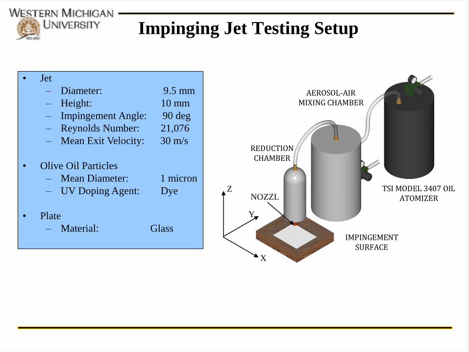
Impinging Jet Testing Setup
• Jet
– Diameter: 9.5 mm
– Height: 10 mm
– Impingement Angle: 90 deg
– Reynolds Number: 21,076
– Mean Exit Velocity: 30 m/s
• Olive Oil Particles
– Mean Diameter: 1 micron
– UV Doping Agent: Dye
• Plate
– Material: Glass
(a)
IMPINGEMENT SURFACE
TSI MODEL 3407 OIL ATOMIZER
AEROSOL-AIR MIXING CHAMBER
REDUCTION CHAMBER
NOZZL
E
Z
Y
X
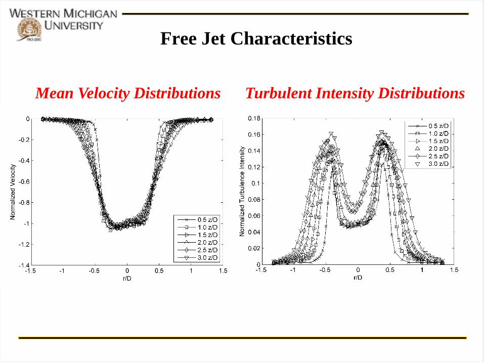
Free Jet Characteristics
Mean Velocity Distributions Turbulent Intensity Distributions
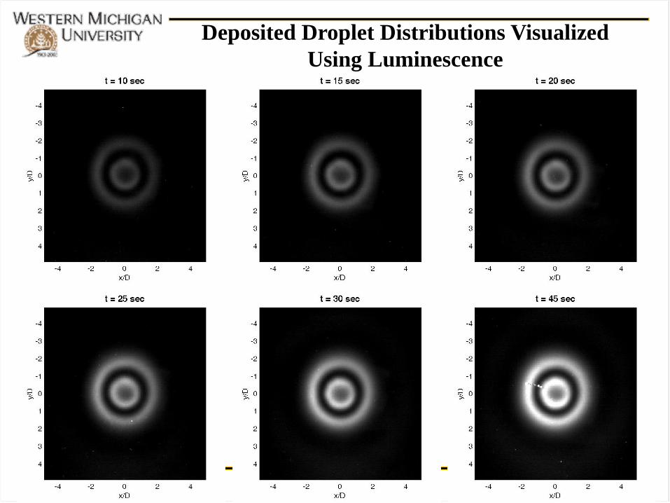
Deposited Droplet Distributions Visualized
Using Luminescence
Deposition Rings & Self-Similar Growth
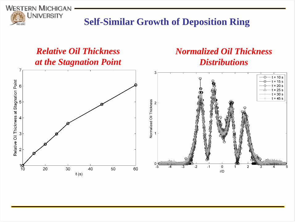
Self-Similar Growth of Deposition Ring
Relative Oil Thickness
at the Stagnation Point
Normalized Oil Thickness
Distributions

Microscopic Images at 400x of Droplet Deposition
• Microscopic inspection
shows that the ring structure
is created by discrete
individual droplets, not the
creation of an oil film.
• Image analysis will
determine oil droplet size
distribution and density
Select Sequential Line Segment -
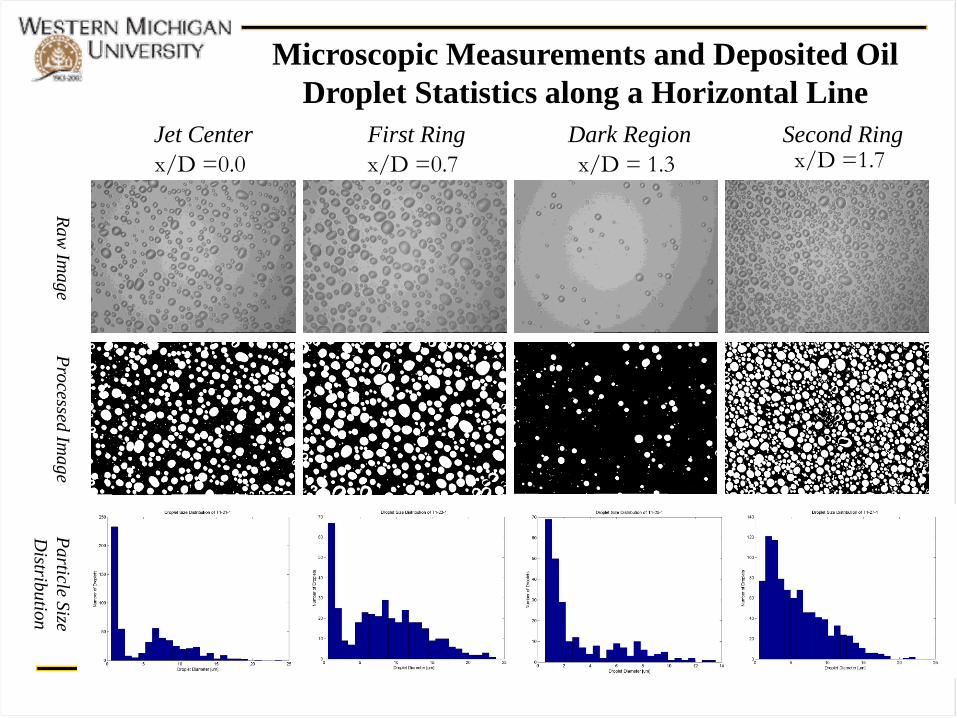
Microscopic Measurements and Deposited Oil
Droplet Statistics along a Horizontal Line
x/D =0.0 x/D =0.7 x/D =1.7 x/D = 1.3
Jet Center First Ring Dark Region Second Ring
Ra
w Im
ag
e P
rocessed
Ima
ge
Pa
rticle Size
Distrib
utio
n
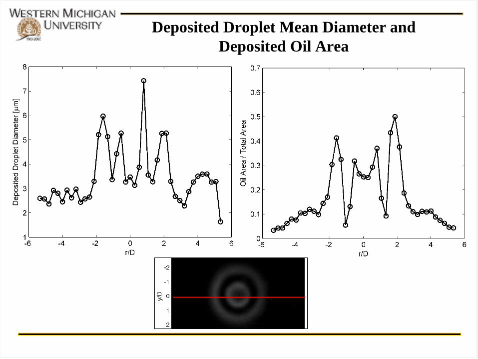
Deposited Droplet Mean Diameter and
Deposited Oil Area
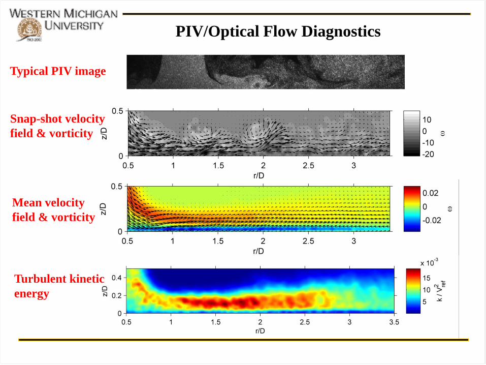
PIV/Optical Flow Diagnostics
Typical PIV image
Snap-shot velocity
field & vorticity
Mean velocity
field & vorticity
Turbulent kinetic
energy
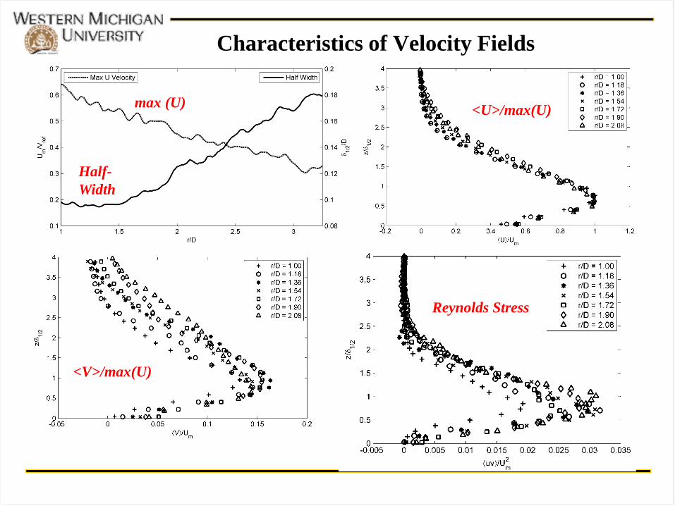
Characteristics of Velocity Fields
max (U)
Half-
Width
<U>/max(U)
<V>/max(U)
Reynolds Stress
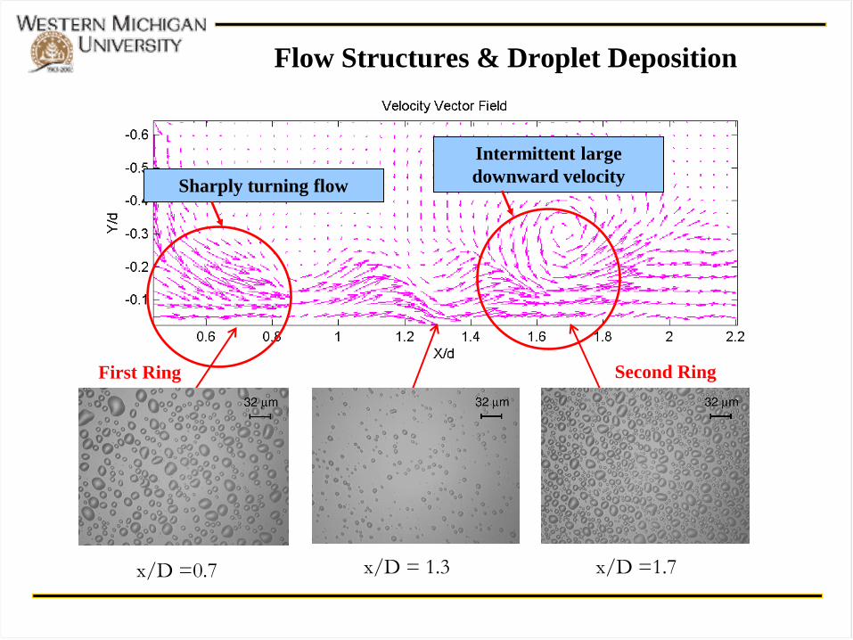
Flow Structures & Droplet Deposition
Intermittent large
downward velocity Sharply turning flow
x/D =0.7 x/D = 1.3 x/D =1.7
First Ring Second Ring
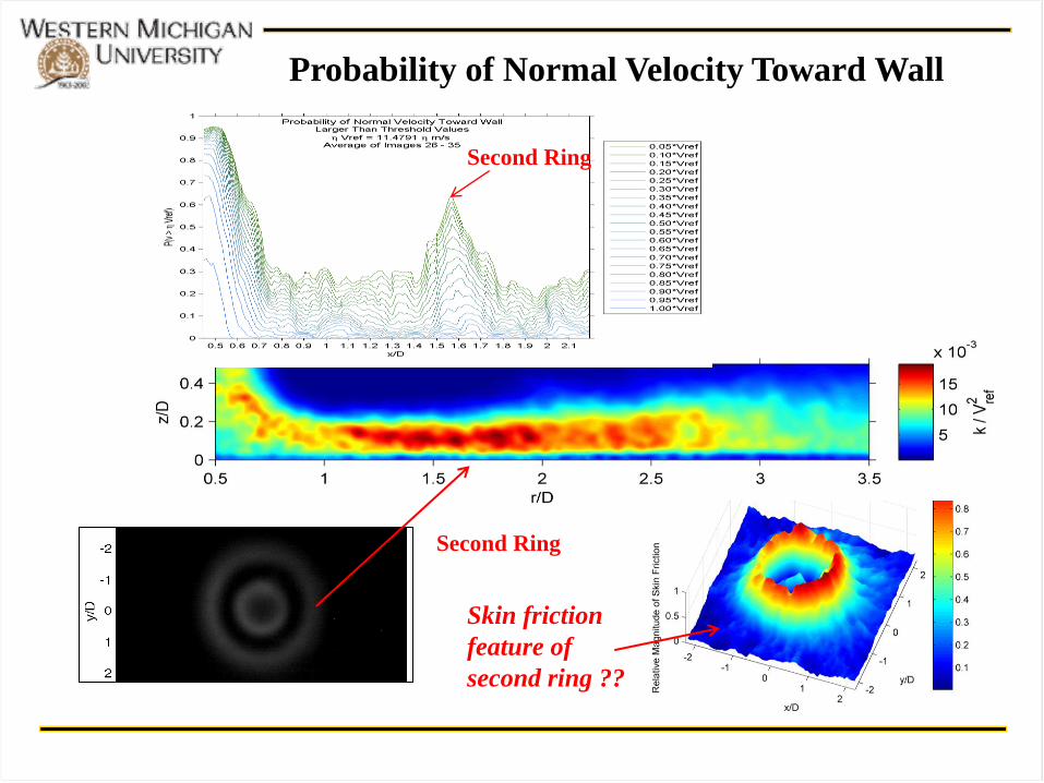
Probability of Normal Velocity Toward Wall
Second Ring
Skin friction
feature of
second ring ??
Second Ring
(a)
(b)
(c)
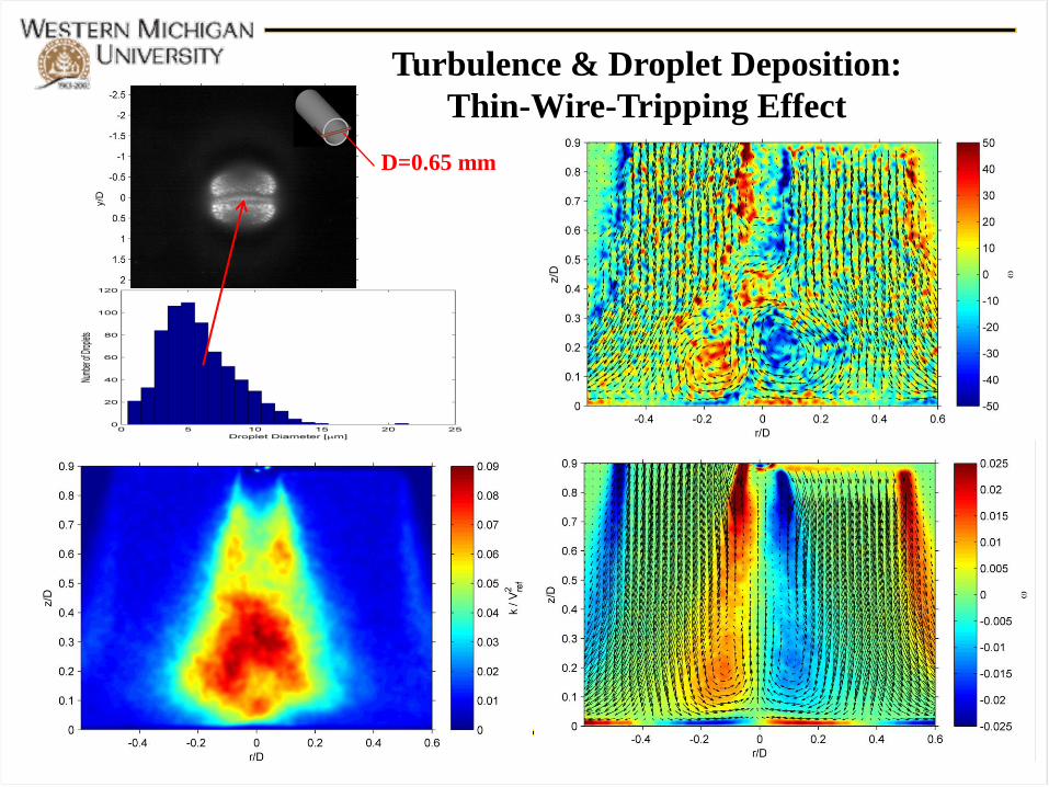
Turbulence & Droplet Deposition:
Jet Nozzle Height Effect
H/D = 0.35
H/D = 1.58
H/D = 2.63
Turbulence & Droplet Deposition:
Thin-Wire-Tripping Effect
D=0.65 mm
(a)
(b)
(c)
(d)
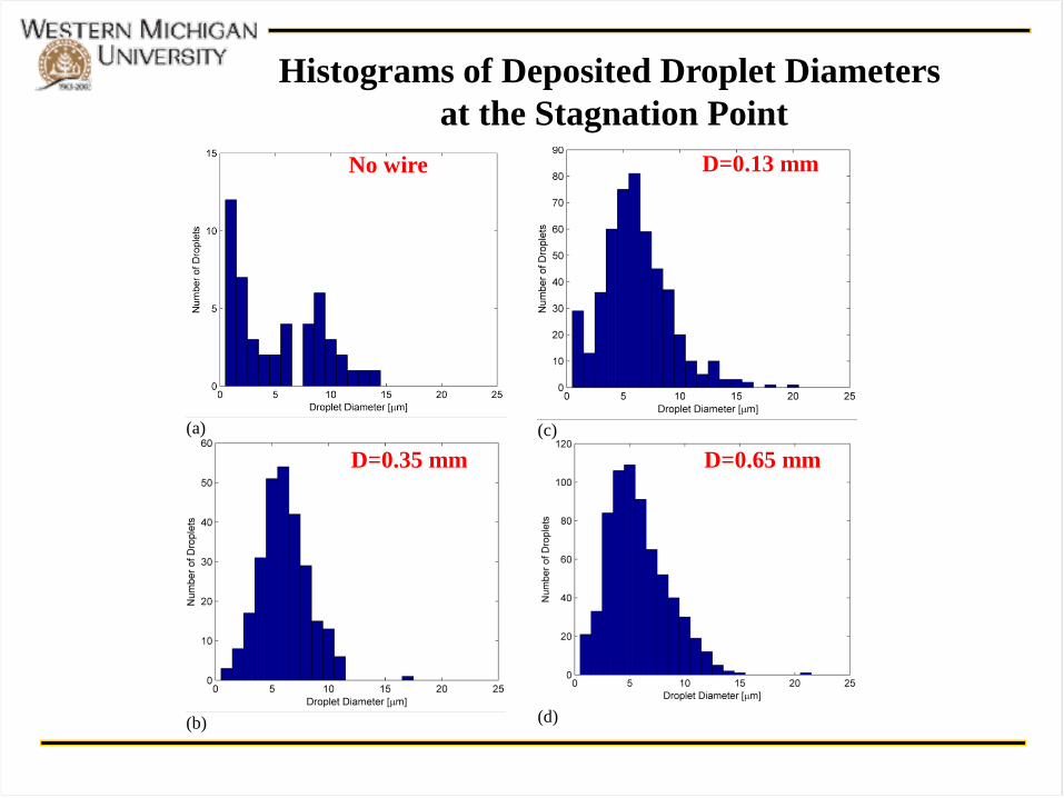
Histograms of Deposited Droplet Diameters
at the Stagnation Point
D=0.65 mm D=0.35 mm
D=0.13 mm No wire

Effect of Turbulent Kinetic Energy on Droplet
Deposition
Relative Deposited Oil Area Integral of Deposited Oil Distribution
● Inner Ring
– The inner ring is formed from sharp turning of the jet
at the wall. The larger droplets no longer follow the
airflow path due to their inertia in the turning, and
they deposit upon the wall forming the inner ring.
● Outer Ring
– The outer ring is created by high turbulence intensity
and intermittent downward velocity induced by large
vortical structures to entrain droplets to the wall.
Summary of Experimental Results
Small-scale turbulence induces droplet collision
to form larger droplets.
● Effect of Small-Scale Turbulence
Why ???
Why do small droplets tend to collide each other
to form larger ones in small-scale turbulence?
A Theoretical Problem Related to the
Experimental Observations
Probability Density Function (PDF) of
Inter-Particle Separation in Turbulence
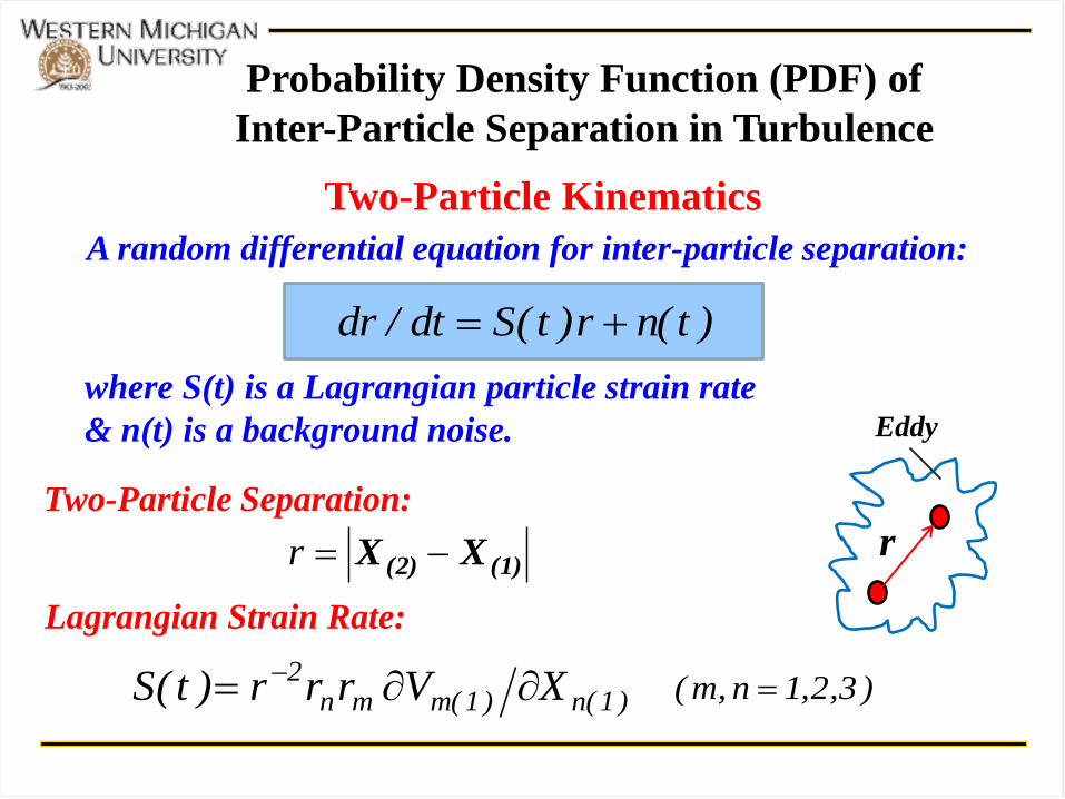
A random differential equation for inter-particle separation:
where S(t) is a Lagrangian particle strain rate
& n(t) is a background noise.
Two-Particle Kinematics
)t(nr)t(Sdt/dr
r
Eddy
)1(n)1(mmn2 XVrrr)t(S
)3,2,1n,m(
(1)(2) XX r
Two-Particle Separation:
Lagrangian Strain Rate:
r
)t,r(p)r(N
r2
1)t,r(p)r(M
r
)r(N
4
1
rt
t)p(r,
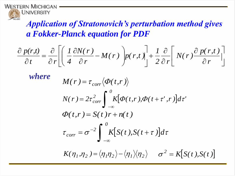
Application of Stratonovich’s perturbation method gives
a Fokker-Planck equation for PDF
)r,t()r(M corr
'd)r,'t(),r,t(K2)r(N
02corr
)t(nr)t(S)r,t(
d)t(S),t(SK
02
corr
where
)t(S),t(SK2 212121 ),(K
The Steady-State Solution for PDF
dr
arara
nrSexp
arara
C)r(p
r
r 322
12/1
322
1 0
The Pearson System
d)t(S),t(SKa
0
1
d)t(S),t(nK)t(n),t(SKa
0
2
d)t(n),t(nKa
0
3
where
13.0)t(S f 4.1corr 18.0)t(Scorr Estimates:
What is a Physically Feasible Solution for PDF ??
322
1 arara
nrS
dr
)r(glnd
The Pearson System:
Gaussian Distribution: 0aa 21 0n
Excluded Solutions:
Gamma Distribution: 0a1 3122 aa4a 0a/S 3
0a1 since it represents the integral timescale of S(t)
0S 0a3 since material lines are always stretched
in turbulence in a mean sense
3122 aa4a violates the Schwartz inequality in mathematics
Reasons:
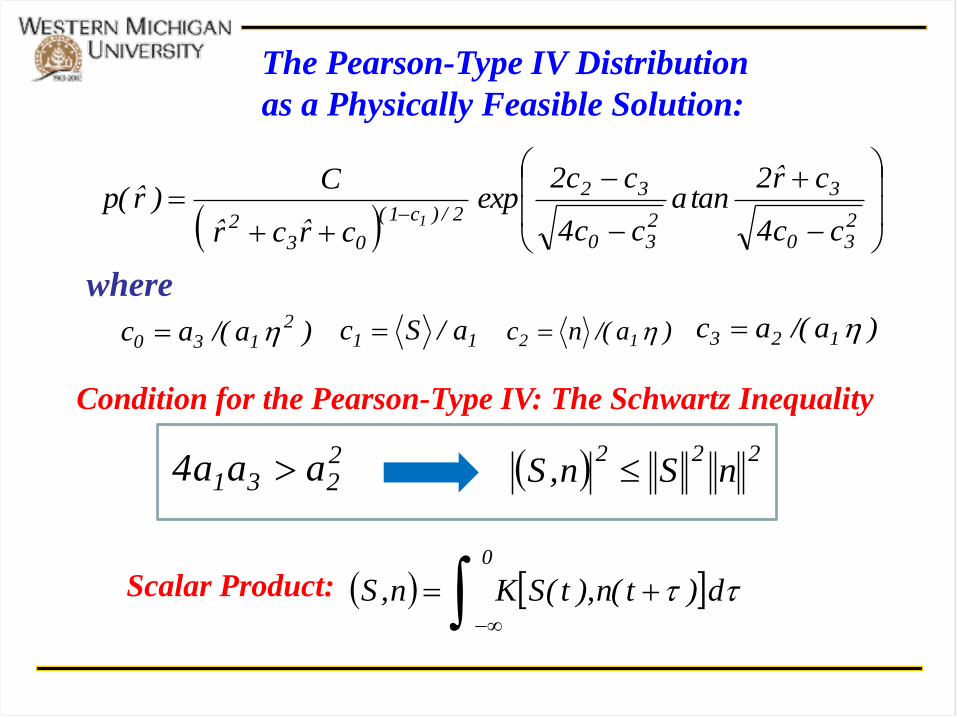
The Pearson-Type IV Distribution
as a Physically Feasible Solution:
230
3
230
32
2/)c1(
032 cc4
cr̂2tana
cc4
cc2exp
cr̂cr̂
C)r̂(p
1
)a/(ac 2130 11 a/Sc )a/(nc 12 )a/(ac 123
where
2231 aaa4 222
nSn,S
d)t(n),t(SKn,S
0
Condition for the Pearson-Type IV: The Schwartz Inequality
Scalar Product:
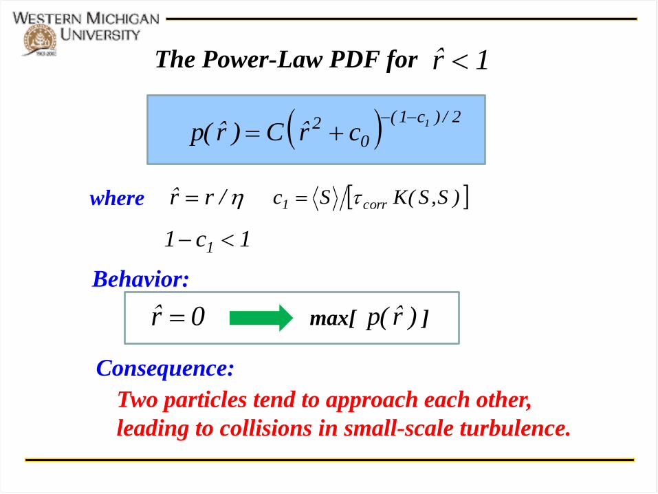
The Power-Law PDF for
where
2/)c1(
02 1
cr̂C)r̂(p
/rr̂
1r̂
)S,S(KSc corr1
1c1 1
0r̂ )r̂(pmax[ ]
Behavior:
Consequence:
Two particles tend to approach each other,
leading to collisions in small-scale turbulence.
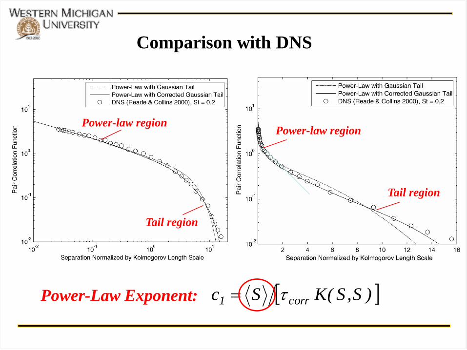
Power-law region
Tail region
Power-law region
Tail region
Comparison with DNS
)S,S(KSc corr1 Power-Law Exponent:
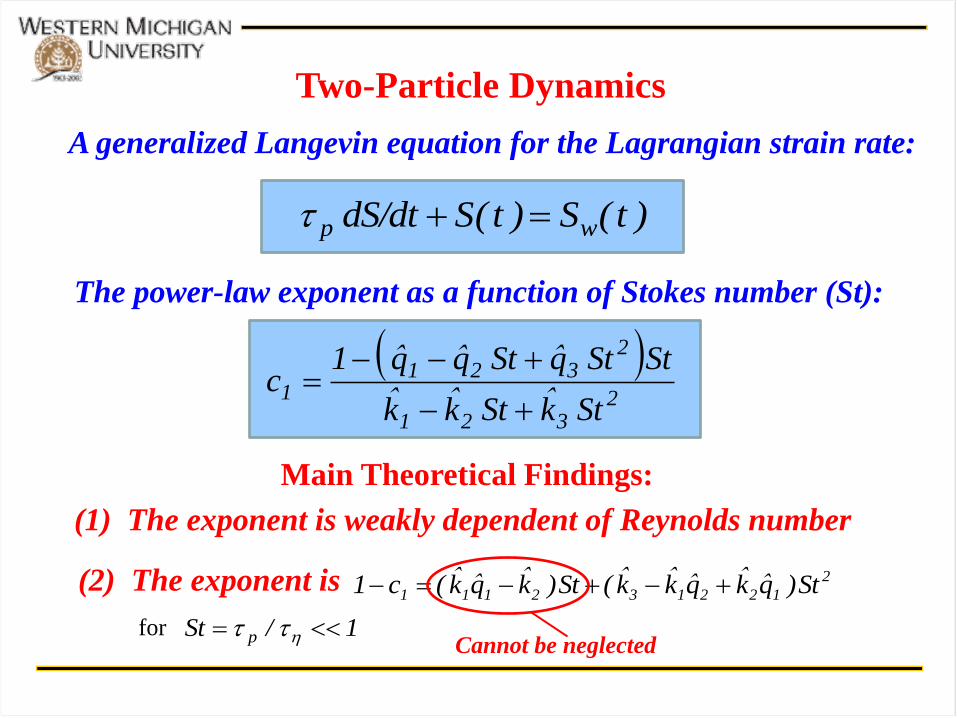
Two-Particle Dynamics
)t(S)t(SS/dtd wp
The power-law exponent as a function of Stokes number (St):
1/St p
(1) The exponent is weakly dependent of Reynolds number
(2) The exponent is 2
122132111 St)q̂k̂q̂k̂k̂(St)k̂q̂k̂(c1
for
Main Theoretical Findings:
A generalized Langevin equation for the Lagrangian strain rate:
2
321
2321
1Stk̂Stk̂k̂
StStq̂Stq̂q̂1c
Cannot be neglected
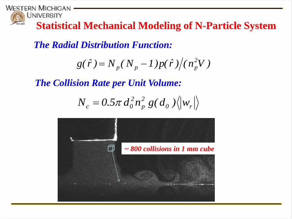
Statistical Mechanical Modeling of N-Particle System
The Radial Distribution Function:
)Vn()r̂(p)1N(N)r̂(g 2
ppp
The Collision Rate per Unit Volume:
r0
2
p
2
0c w)d(gnd5.0N
~ 800 collisions in 1 mm cube
Conclusions
The formation of the outer ring is caused by high
turbulence activities through the following
mechanisms:
(a) Large-scale vortical structures entrain droplets
toward the wall.
(b) Small-scale turbulence induces droplet collisions to
form larger droplets.