Fluid Flow in Polymer Electrolyte Membrane Fuel...
24
12 Fluid Flow in Polymer Electrolyte Membrane Fuel Cells Alfredo Iranzo, Antonio Salva and Felipe Rosa Thermal Engineering Group, Energy Engineering Department School of Engineering, University of Seville Spain 1. Introduction Polymer Electrolyte Membrane Fuel Cells (PEMFC) have attracted significant interest during the last few decades, as they are considered to be one of the most promising alternative clean power generation devices for portable, mobile and stationary applications. However, different technological barriers such as cost, durability, or heat and water management, are limiting the implementation of fuel cell systems into the global energy markets, and therefore significant research efforts and investments are being carried out. Fuel cells are devices where electrochemical reactions transform chemical energy available in fuels into electrical energy. Fuel cells are not limited by the thermodynamic restrictions of conventional power generation systems, such as the Carnot efficiency, meaning that fuel cells can be operated with higher efficiency for energy conversion. Additionally, the environmental impact is low as no combustion processes occurs and no pollutants are generated (U.S. Department of Energy [DOE], 2004). A typical fuel cell power system consists of different components: - Single cells, where the electrochemical reactions occur. - Stacks, consisting of the necessary number of cells electrically connected to provide the required power capacity. - The balance of plant, or additional equipment to provide fuel and oxidants with the appropriate conditions, thermal management, electric power conditioning, and other functions. Single or unit cells are the core of a fuel cell. They convert the chemical energy contained in a fuel into electrical energy, via electrochemical reactions. The basic configuration of a fuel cell consists of an electrolyte layer or membrane in contact with an anode and a cathode on either side. In a PEM fuel cell, hydrogen is continuously supplied to the anode or negative electrode, and an oxidant, often oxygen or air, is also continuously supplied to the cathode or positive electrode. Electrochemical reactions occur at the electrodes, generating an electric current through the electrolyte thus driving the corresponding electric current that performs the electric work on the load. At the anode, hydrogen is fed to the cell and a reaction takes place at the catalyst layer: 2 2 4 4 H H e + - → + (1) www.intechopen.com
Transcript of Fluid Flow in Polymer Electrolyte Membrane Fuel...

12
Fluid Flow in Polymer Electrolyte Membrane Fuel Cells
Alfredo Iranzo, Antonio Salva and Felipe Rosa Thermal Engineering Group, Energy Engineering Department
School of Engineering, University of Seville Spain
1. Introduction
Polymer Electrolyte Membrane Fuel Cells (PEMFC) have attracted significant interest during the last few decades, as they are considered to be one of the most promising alternative clean power generation devices for portable, mobile and stationary applications. However, different technological barriers such as cost, durability, or heat and water management, are limiting the implementation of fuel cell systems into the global energy markets, and therefore significant research efforts and investments are being carried out. Fuel cells are devices where electrochemical reactions transform chemical energy available in fuels into electrical energy. Fuel cells are not limited by the thermodynamic restrictions of conventional power generation systems, such as the Carnot efficiency, meaning that fuel cells can be operated with higher efficiency for energy conversion. Additionally, the environmental impact is low as no combustion processes occurs and no pollutants are generated (U.S. Department of Energy [DOE], 2004). A typical fuel cell power system consists of different components: - Single cells, where the electrochemical reactions occur. - Stacks, consisting of the necessary number of cells electrically connected to provide the
required power capacity. - The balance of plant, or additional equipment to provide fuel and oxidants with the
appropriate conditions, thermal management, electric power conditioning, and other functions.
Single or unit cells are the core of a fuel cell. They convert the chemical energy contained in a fuel into electrical energy, via electrochemical reactions. The basic configuration of a fuel cell consists of an electrolyte layer or membrane in contact with an anode and a cathode on either side. In a PEM fuel cell, hydrogen is continuously supplied to the anode or negative electrode, and an oxidant, often oxygen or air, is also continuously supplied to the cathode or positive electrode. Electrochemical reactions occur at the electrodes, generating an electric current through the electrolyte thus driving the corresponding electric current that performs the electric work on the load. At the anode, hydrogen is fed to the cell and a reaction takes place at the catalyst layer:
22 4 4H H e+ −→ + (1)
www.intechopen.com

Fluid Dynamics, Computational Modeling and Applications 266
The protons migrate through the polymeric membrane and react with the oxygen and the electrons at the cathode catalyst layer:
2 24 4 2O H e H O+ −+ + → (2)
Therefore, the overall reaction taking place in the cell is:
2 2 22 2H O H O+ → (3)
Fuel cells are modular, so that unit cells can be combined into a stack to achieve the voltage and power required for the specific application. This involves connecting multiple unit cells in series via electrically conductive materials. The connection is achieved via the bipolar plate (BP), that also provides a gas barrier that separates the fuel and oxidant of adjacent cells (DOE, 2004), (Larminie & Dicks, 2003), (Barbir, 2005). The channels that distribute the gas to the electrode surface are usually imprinted in the plate. The design of a fuel cell must therefore comprise a number of physical and chemical phenomena, such as electrochemical reactions, heat transfer and thermal management, material selection, fluid dynamics for laminar flow and flow in porous media, flow distribution of the reactants in the stack manifolds, and others. These phenomena are tightly coupled, making the design and optimization of a fuel cell a complicated task usually aided by numerical models and simulations, as well as by experimental techniques. A considerable effort and intense developments are being made by governments, public institutions, universities, research institutes and private companies in the field of fuel cell research. In this chapter, the fluid flow within single cells and fuel cell stacks is analysed.
2. Fluid flow in PEM fuel cells
The fluid flow characteristics within the Fuel Cell are of major importance for the final
performance of the system. This chapter deals with the main fluid flow mechanisms
occurring within a Fuel Cell at two different levels: single cells and stacks.
The flow inside a single cell comprises a number of different transport mechanisms, namely
laminar flow in channels, flow in porous media, multiphase flow with phase change, and
diffusion mechanisms. This will be addressed in section 3. On the other hand, the flow in a
Fuel Cell stack is mainly concern about the flow in the inlet/outlet stack manifolds, and the
reactant distribution over the different cells. This will be addressed in section 4.
3. Fluid flow in a single cell
3.1 Description of a single cell: Main components and processes The core of a single cell is a polymer membrane acting as an electrolyte. The membrane is a proton-conductive material, with porous electrodes on both sides of the membrane. The electrodes are porous materials to allow both reactant gases to reach the catalyst sites and products to leave the electrode. Electrochemical reactions occur at the catalyst surface on the electrodes. This multilayer assembly is called Membrane Electrode Assembly (MEA). The MEA is located between collector or separator plates called bipolar plates. Bipolar plates connect the cathode of one cell to the anode of the adjacent cell both physically and electrically. Reactant gases are fed to the Bipolar Plates, where imprinted channels distribute
www.intechopen.com
Fluid Flow in Polymer Electrolyte Membrane Fuel Cells 267
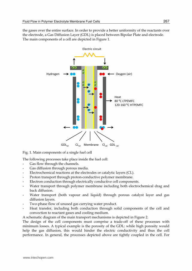
the gases over the entire surface. In order to provide a better uniformity of the reactants over the electrode, a Gas Diffusion Layer (GDL) is placed between Bipolar Plate and electrode. The main components of a cell are depicted in Figure 1.
Fig. 1. Main components of a single fuel cell
The following processes take place inside the fuel cell: - Gas flow through the channels. - Gas diffusion through porous media. - Electrochemical reactions at the electrodes or catalytic layers (CL). - Proton transport through proton-conductive polymer membrane. - Electron conduction through electrically conductive cell components. - Water transport through polymer membrane including both electrochemical drag and
back diffusion. - Water transport (both vapour and liquid) through porous catalyst layer and gas
diffusion layers. - Two-phase flow of unused gas carrying water product. - Heat transfer, including both conduction through solid components of the cell and
convection to reactant gases and cooling medium. A schematic diagram of the main transport mechanisms is depicted in Figure 2. The design of the cell components must comprise a trade-off of these processes with minimum losses. A typical example is the porosity of the GDL: while high porosity would help the gas diffusion, this would hinder the electric conductivity and thus the cell performance. In general, the processes depicted above are tightly coupled in the cell. For
Hydrogen Oxygen (air)
Electric circuit
Heat
80 ºC LTPEMFC
120-160 ºC HTPEMFC
e-e-
e-e-
e- e-
e-
e-
e-
e-
H+
H+
H+
H+
GDLan CLan Membrane Clcat GDL cat
www.intechopen.com

Fluid Dynamics, Computational Modeling and Applications 268
example, at the cathode side of the MEA a complex interrelation between various transport phenomena take place. The processes occurring at the cathode are (Djilali, 2007): - Conduction of electrons between the current collectors and the reaction sites. - Conduction of protons between the membrane and catalyst layer. - Transport of the reactants to the catalyst layer. - Transport of heat away from the reaction site primarily through the solid matrix. - Condensation/evaporation and transport of liquid water and vapour.
Fig. 2. Main processes within a single PEM fuel cell
On the cathode, the reaction is likely to suffer from mass transport limitations at high current densities, when depletion of oxygen in the air stream becomes significant. This limitation can be further extended by flooding of the electrode pores by the product water and blocking of pathways for oxygen transport to the reaction sites. Effective removal of excess water is thus essential, but must be balanced against the need to prevent drying of the adjacent proton conducting media (membrane), which not only causes deterioration in protonic conductivity (and thus higher ohmic losses and lower efficiency), but also impacts durability. The performance of a fuel cell is usually represented by means of a polarization curve I-V as shown in Figure 3. In the polarization curve, three different regions can be generally observed. The cell performance is dominated by kinetic or activation losses at low current densities, while at high current densities mass transport limitations have a major effect given the high amount of reactants required to maintain the intensity and the pore blockage produced by the water flooding the cathode. At medium current densities and voltages, ohmic losses become an important factor in the fuel cell performance.
Hydrogen Oxygen (air)
e-
e-
e-
e-e-
e-e-e-
H+
H+
H+
H+
Electro-
osmotic drag
Back-diffusion
e- e-
e-e-
e- e-
e- e-
e- e-
Channel GDL CL Mem CL* GDL Channel
O2 transport (voids): diffusion
e- transport (conductive fibers)
Water transport (voids): diffusion, capillary, phase change
H2 transport (voids): diffusion
e- transport (conductive fibers)
* Water generation (catalyst sites) and transport
Anode Membrane Cathode
www.intechopen.com

Fluid Flow in Polymer Electrolyte Membrane Fuel Cells 269
Fig. 3. Polarization curve of a single PEM fuel cell
The performance of a given fuel cell is affected by the parameters listed below (Barbir, 2005): - Temperature - Pressure - Reactant flow rates (reactant utilization) - Reactant composition (humidification, fuel and oxidant concentration) - Current density - Other parameters: reactant impurities, cell components degradation, etc. From thermodynamics and electrochemical reaction kinetics, the Fuel Cell performance is higher when the operating pressure and temperature is increased. However, the complete system and balance of plant must be considered for the appropriate selection of the operating parameters (compression power, water management, etc.). Regarding reactant flow rates, generally speaking higher flow rates result in improved performance of the fuel cell, as higher flow rate helps remove liquid water from the cell and maintain a high oxygen concentration within the catalyst layer. However, when hydrogen is considered, a too high flow rate will reduce the system efficiency as part of the hydrogen would be wasted. In Nafion membranes, reactants must be supplied humidified in order to keep the membrane sufficiently hydrated and enhance its protonic conductivity. A complex water transport and management issues arises, with water being generated at the cathode, and transported by means of different mechanisms through the cell. The degree of humidification required depends on the cell design and membrane type. For example, thinner membranes such as Nafion-111 present a better cathode to anode water transport via diffusion. Water management is one of the most active research fields in PEM Fuel Cells, and detailed reviews can be found in the work of Dai et al. (Dai et al., 2009) and Jiao and Li (Jiao & Li, 2011). The real potential obtained in a fuel cell is always less than the theoretical maximum, as certain irreversible losses exist. The main contributions to the losses are (Barbir, 2005; Mench 2008): - Activation losses:
Activation losses area caused the activation energy needed for the electrochemical reactions at the electrodes. The kinetics of the reactions results in part of the voltage generated being used as driving force for the chemical reaction.
www.intechopen.com

Fluid Dynamics, Computational Modeling and Applications 270
Therefore these losses depend on the reactions taking place, the properties of the electro-catalyst material and its microstructure, among others.
- Ohmic losses: The voltage drop caused by ohmic losses represents the resistance to the flow of electrons through the materials and contact resistance, and the ionic resistance in the electrolyte. This is mainly proportional to the current density, and also depends on the material properties, cell geometry and working temperature.
- Mass transport or concentration losses: Both fuel and oxidant must be transported to the electrodes surface as they are being consumed. There are transport limitations depending of the current density, reactant activity and electrode and GDL microstructure, and therefore the concentration of the reactants at the surface of the electrodes is reduced. At high current densities where water generation at the cathode is significant, liquid water being transported through the catalyst layer and GDL partially blocks the pores and the catalyst sites (flooding), thus leading to a limitation in the oxygen transport and reaction. This is considerably affecting the output voltage lowering the performance of the cell at high current densities (Li et al., 2008).
The high degree of coupling between all of the processes occurring within the cell makes
necessary an overall approach for the analysis of the fuel cell. A well-established approach
must account for all these processes, otherwise severe errors in the design can occur. For
example, consider a design criteria based on the reactant transport from the channel to the
catalytic layer. If no current transport is considered, no electric contact resistance between
the GDL and the BP will be included in the study, and therefore the designer will probably
reach the conclusion that a high channel-to land ratio optimises the performance. However,
with a too high channel-to land ratio, the electric contact resistance between GDL and BP is
increasing and the cell performance drops significantly.
The following subsections provide an insight into the main fluid flow phenomena within a
single cell.
3.2 Fluid flow in the bipolar plate channels The fluid flow in Bipolar Plate channels is always laminar in PEM Fuel Cells given the low
Reynolds number found, generally in the range 50-500.
Re = ρVD/┤ (4)
where Re is the Reynolds number (dimensionless), ρ and ┤ are the fluid density and
dynamic viscosity, V is the fluid velocity and D the channel hydraulic diameter. For anode
and cathode, channel square section is around 1 mm x 1mm, with gas velocities in the range
0.1-5 m/s. Laminar flow is therefore found in the flow field of Bipolar Plates.
The equations governing the general fluid flow are the Navier-Stokes equations, also known
as conservation or transport equations, which can be written in its general form as:
擢擢痛 完 貢∅穴撃蝶 + ∮ 貢∅撃 · 穴畦 =凋 ∮ Γ∇∅ · 穴畦凋 + 完 鯨∅穴撃蝶 (5)
Where φ is the transported quantity, t is the time, A the superficial area, V the volume, Γ is
transported quantity diffusivity, and Sφ is the source of φ. The first term in the equation
corresponds to the transient transport of φ, the second term to the transport by convection
www.intechopen.com

Fluid Flow in Polymer Electrolyte Membrane Fuel Cells 271
mechanism, the third term represents the transport of φ by diffusion, and the fourth term
represents the source (or sink) of φ. The different transport equations are assembled by using the appropriate variables, as shown in Table 1.
Equation Variable φ
Continuity 1
x-momentum u (velocity in x-direction)
y-momentum v (velocity in y-direction)
z-momentum w (velocity in z-direction)
Energy h (enthalpy)
Chemical specie i yi (mass fraction of i)
Table 1. Main transport equations
There are different types of flow field designs for Bipolar Plates. Pin-type and parallel flow fields are found in many fuel cells, although the most widely used design in industry is the serpentine flow field (Li & Sabir, 2005). Some experimental techniques are available for flow visualization in Bipolar Plates (Barreras et al., 2005), but numerical modelling has been established as a powerful tool for flow analysis and cell components design (Djilali, 2007). For example, Fig. 4 presents CFD results for the flow distribution in the channels of a parallel flow field Bipolar Plate. The corresponding pressure fields are depicted in Fig. 5. Preferential paths that may lead to an uneven reactant distribution over the electrode are clearly observed, enabling the researcher to redesign the flow field for the cell improvement. The results correspond to the work done by Iranzo et al. (Iranzo et al, 2010, 2011a), where a commercial 50 cm2 fuel cell was modelled by means of Computational Fluid Dynamics (CFD), and the numerical results were experimentally validated in a test station for different bipolar plate designs and operating conditions, using the real cells. The details of the CFD model, simulation, and results validation can be found in Iranzo et al. (Iranzo et al, 2010, 2011a).
Fig. 4. Computational Fluid Dynamics simulation of the velocity distribution in a 50 cm2 Bipolar Plate with parallel flow field design (cathode side). Left: 100 mA/cm2. Right: 600 mA/cm2.
www.intechopen.com

Fluid Dynamics, Computational Modeling and Applications 272
Fig. 5. Computational Fluid Dynamics simulation of pressure distribution in a 50 cm2 Bipolar Plate with parallel flow field design (cathode side). Left: 100 mA/cm2. Right: 600 mA/cm2.
However, as the physical and electrochemical phenomena within a fuel cell is highly coupled, it is in general necessary to work with a more complete model considering the fundamental phenomena, in order to accurately represent the cell. For that, the N-S equations listed above (Eq. 5) can be augmented to account for different physical and chemical phenomena relevant to fuel cells such as electrochemistry, flow in porous media and multiphase flow. An excellent review on computational heat and mass transfer modelling for PEMFCs is found in the work by Siegel (Siegel, 2008).
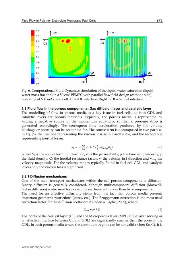
3.2.1 Multiphase flow in the bipolar plate channels The flow in the Bipolar Plate channels is not always a single flow problem. Especially at high current densities the water generation (Eq. 2, Eq. 3) can be large enough for establishing a two-phase flow. This is particularly important in the catalyst layer and GDL, as the liquid water blocks the catalyst sites and GDL pores, inducing a high resistance for the oxygen transport. Regarding the channels, liquid water emerges from the GDL and enters the channel in the form of droplets. A complex droplet dynamics is established then in the channel, where the water is dragged by the reactant flow towards the exit. Depending on the gas flow rate and the wall contact angle, the flow regime in the channel can be a mist, a plug or slug flow, or a film flow. Liquid water must be efficiently evacuated from the cell, in order to ensure an adequate path for the oxygen to reach the catalyst sites. The two-phase flow can be visualized by means of advanced experimental techniques such as neutron imaging (Park et al., 2008; Wu et al., 2008b), but again Computational Fluid Dynamics is used by many researchers for the investigation of two-phase flow in fuel cells, although it is one of the most complex modelling tasks currently (Wang, 2004). Fig.6 presents results for the liquid water concentration in a fuel cell with parallel flow field. This particular flow field design is known to be inadequate for handling liquid water, as droplets typically collapse one of the channels (red spots in the Fig. 6), the gas flow finds a high local resistance, and as other channels are still empty the flow is unable to flush the accumulated water (Li & Sabir, 2005).
www.intechopen.com
Fluid Flow in Polymer Electrolyte Membrane Fuel Cells 273
Fig. 6. Computational Fluid Dynamics simulation of the liquid water saturation (liquid water mass fraction) in a 50 cm2 PEMFC with parallel flow field design (cathode side) operating at 600 mA/cm2. Left: CL-GDL interface. Right: GDL-channel interface.
3.3 Fluid flow in the porous components: Gas diffusion layer and catalytic layer The modelling of flow in porous media is a key issue in fuel cells, as both GDL and catalytic layers are porous materials. Typically, the porous media is represented by adding a negative source in the momentum equations, so that a pressure drop is generated accordingly. The consequent flow acceleration produced by the volume blockage or porosity can be accounted for. The source term is decomposed in two parts as in Eq. (6), the first one representing the viscous loss as in Darcy´s law, and the second one representing inertial losses.
鯨沈 = −岾禎底 懸沈 + 系態 怠態 貢懸陳銚直懸沈峇 (6)
where Si is the source term in i direction, α is the permeability, µ the kinematic viscosity, ρ the fluid density, C2 the inertial resistance factor, vi the velocity in i direction and vmag the velocity magnitude. For the velocity ranges typically found in fuel cell GDL and catalytic layers only the viscous loss is significant.
3.3.1 Diffusion mechanisms One of the main transport mechanisms within the cell porous components is diffusion. Binary diffusion is generally considered, although multicomponent diffusion (Maxwell-Stefan diffusion) is also used for non-dilute mixtures with more than two components. The need for an effective diffusivity stems from the fact that porous media presents important geometric restrictions (pores, etc.). The Bruggemann correction is the most used correction factor for the diffusion coefficient (Sundén & Faghri, 2005), where:
Deff = ε1.5 D (7)
The pores of the catalyst layer (CL) and the Microporous layer (MPL, a fine layer serving as an effective interface between CL and GDL) are significantly smaller than the pores in the GDL. In such porous media where the continuum regime can be not valid (when Kn>1), it is
www.intechopen.com

Fluid Dynamics, Computational Modeling and Applications 274
necessary to account for the Knudsen diffusion mechanism. The transition is determined by the Knudsen number:
Kn = λ / dpore (8)
The diffusion coefficient is then determined from the kinetic theory of gases (Sundén & Faghri, 2005).
3.3.2 Multiphase flow in porous components: Capillary forces Multiphase flow on the cathode side represents a main concern for the practical operation
and performance of a fuel cell, given the potential flooding of the porous CL and GDL, and
represents currently one of the main areas of research in the field of PEM fuel cells.
PEM fuel cells operate under 100 °C, thus water vapour formed during the operation of the
cell may condense to liquid water. This is especially true at higher current densities when
the reaction rates are higher and therefore water production becomes important. An excess
of reactant in the cathode side helps evacuating liquid water, but increases the parasitic
power associated to gas compressors.
The production of water takes place in the cathode catalyst layer due to the oxygen
reduction reaction (ORR). Another source of water is the humidification of the reactants.
Different transport mechanisms through the membrane are available for water: electro-
osmotic drag, proportional to the protonic flux, and diffusion, proportional to the water
molar concentration gradient. Both effects operate in opposite directions and a correct
water management implies a zero net water transport so that membrane and electrodes
becomes neither flooded nor dried-out. Water management depends as well on the
membrane thickness. Thin membranes such as Gore or Nafion-111 enhances the water
back-diffusion from cathode to anode, but thick membranes such as Nafion-112 or 117
reduces the diffusion transport.
A correct amount of water is needed to keep the membrane hydrated, but excessive water
blocks the porous media and reduces the mass transport rate by diffusion and also reduces
the active reacting surface area, and therefore the cell performance. This is why correctly
modelling water formation and transport is a key issue in predicting the cell behaviour with
accuracy. Different types of multi-phase models have been used in the literature, such as the
mixture model, the multifluid model, and the saturation model. A complete revision of the
different modelling approaches can be found in the work by Wang (Wang, 2004). One of the
modelling approaches is the saturation model, where a multi-component single phase
system is resolved, with an additional equation accounting for the liquid saturation. The
conservation equation for the liquid water volume fraction or water saturation, s, is solved:
擢岫悌諦如鎚岻擢痛 + ∇ · 盤貢鎮撃鎮屎屎屎王嫌匪 = 堅栂 (9)
where the subscript l stands for liquid water, and rw is the condensation rate, modelled as a function of the difference between vapour partial pressure and saturation pressure. As a first approach the liquid velocity Vl can be assumed to be equivalent to the gas velocity inside the gas channel, so that the liquid droplets would be a fine mist. Inside the porous zones the use of the capillary diffusion term allows the replacement of the convective term in Equation (9). The capillary pressure can be calculated as a function of s, depending on the wetting phase:
www.intechopen.com

Fluid Flow in Polymer Electrolyte Membrane Fuel Cells 275
喧頂 = 畔蹄頂墜鎚提迩盤凪売匪轍.天 岫な.ねに岫な − 嫌岻 − に.なに岫な − 嫌岻態 + な.には岫な − 嫌岻戴岻肯頂 < ひど°蹄頂墜鎚提迩盤凪売匪轍.天 岫な.ねに嫌 − に.なに嫌態 + な.には嫌戴岻肯頂 > ひど° (10)
Where σ is the surface tension, ε is the porosity, θc is the contact angle and K is the absolute
permeability.
Such approach enables the modelling of various physical processes such as condensation,
vaporization, capillary diffusion, and surface tension. Also the blocking of the porous media
and the flooding of the reaction surface can be modelled by multiplying the porosity and the
active surface area by a factor (1- s), respectively.
The saturation model presented here is used by a number of groups, although it misses the
main phenomena associated to liquid water transport and multiphase flow effects. The
saturation model is in fact an enhanced multicomponent flow model, where different
species coexist in a single-phase medium, rather than a true multi-phase flow model.
Other approaches for the modelling of water transport have been developed and applied by
other research groups. Euler-Euler multiphase-flow is found in many fuel cell models
reported in the literature, as well as Lattice-Boltzmann methods.
3.4 Membrane property models In order to solve the governing equations for the fuel cell it is required to implement
expressions for the various transport properties, especially in the membrane. The membrane
phase is usually modelled as a porous media. There are many physical properties that must
be correctly modelled in order to predict the fuel cell behaviour with accuracy, in particular:
gas phase diffusivities, electrical conductivity, water diffusivity, and osmotic drag
coefficient.
As seen in the modelling equations, the water content is a key variable. It represents a
driving force and an integral part of PEMFC water management, and it is also a crucial
parameter as almost all property expressions depends on it, such as conductivity. Because of
the importance of water content, it has received more modelling attention than other
membrane properties. Such models span from simple curve fits to more elaborate
chemically based models.
There are different methods to determine the transport properties: empirically, semi-
empirically, or by means of modelling. The semi-empirical method is used by most models.
In particular, the polynomial fit of Springer et al. (Springer et al., 1991) is used in many fuel
cell models:
膏 = 犯ど.どねぬ + なば.なぱ欠 − ぬひ.ぱの欠態 + ぬは欠戴岫欠 < な岻なね + な.ね岫欠 − な岻岫欠 > な岻 (11)
where ┣ is the membrane water content, and a is the water activity, defined as Pwv/Psat.
The gas species diffusivities can be modelled as a function of the water saturation s in order
to account for the pore blockage when liquid water is present. An expression is given in Um
et al. (Um et al., 2000):
経沈 = 綱怠.泰岫な − 嫌岻追濡経沈待 岾椎轍椎 峇廷妊 岾脹脹轍峇廷禰 (12)
www.intechopen.com

Fluid Dynamics, Computational Modeling and Applications 276
where Di is the diffusivity of species i at reference temperature and pressure (P0, T0). The exponents and the pore blockage rs are model parameters. Nam and Kaviany (Nam & Kaviany, 2003) provides a detailed discussion on the values of rs. The membrane electric conductivity can be modelled with the expression:
購陳勅陳 = 綱岫ど.のなね膏 − ど.ぬには岻結怠態滞腿盤 迭典轍典貸迭畷匪 (13)
where ┣ is the water content. The membrane osmotic drag coefficient follows the expression:
糠鳥 = に.の 碇態態 (14)
3.5 Transient effects Transient phenomena, such as the dynamic response of the cell with a load change or the cell start-up, adds additional challenges to the analysis of the flow and cell performance. The different time scales associated with the main processes occurring within the cell must be considered. In fuel cells, the water transport phenomena are presenting larger timescales than electrochemical, mass transport, or gas flow timescales. Wang (Wang, 2004) compares the timescales for the different phenomena: the time constant for the electrochemical reaction is known to be typically in the range of micro- and milliseconds. Electrochemical reaction timescales can also be determined experimentally (Iranzo et al, 2011b). The time constant for the transport of the reactant gas through the GDL is estimated by its diffusion time:
2MT GDL gDτ δ= (15)
Where δGDL is the GDL thickness and Dg is the diffusion coefficient. For typical cells, the time constant is in the range between 0.1 and 1 s as stated by Wang (Wang, 2004). Finally, the time constant for the membrane hydration process, associated to multiphase and water transport effects, can be estimated by (Wang, 2004):
2
mH
I
EW F
ρδ λτ
Δ = (16)
Where EW is the membrane equivalent weight, I the intensity, F the Faraday constant, δm the membrane thickness, and λ the water content. This results in a typical time constant of several seconds. Therefore, the differences in the physical and chemical phenomena timescales in a fuel cell are at least within a 103 range.
3.6 Numerical and experimental analysis of fluid flow in PEM fuel cells The main tools available for the analysis of the fluid flow inside fuel cells are the numerical modelling of the system and specific experimental techniques.
3.6.1 Numerical modelling of PEM fuel cells Fuel cell modelling has received much attention over the past 15 years in an attempt to better understand the phenomena occurring within the cell. Models can be used for a wide range of situations and problems within fuel cells, from very simple pre-dimensioning models to complex three-dimensional models covering different physical and chemical phenomena. Therefore, very different models have been developed.
www.intechopen.com

Fluid Flow in Polymer Electrolyte Membrane Fuel Cells 277
In terms of the region of interest, numerical simulation can be divided into modelling at the electrode level or micro-modelling, or at cell or stack level (macro-modelling). The microscopic models provide the fundamental understanding of processes like diffusion and conduction in the membrane on a single-pore or even molecular level. They allow for the evaluation of small perturbations like pores heterogeneity as well as the incorporation of small-scale effects. Such models require a lot more knowledge of the microstructure. To allow modelling of entire PEFC behaviour, macroscopic models are more commonly used, where some microscopic details are included in the model. Computational Fluid Dynamics works at macro-modelling level, aiming at the optimization of different design alternatives and determining operational strategies, incorporating built-in models for the electrochemical performance of the given electrodes and electrolytes. CFD models work either for 2D or 3D problems, where during the last years a high increase in the number of 3D models have been reported in the literature. 3D models allows for a complete representation of the real fuel cell geometry, thus enabling for the evaluation of different cell geometries and for the understanding of the influence of operating conditions. Given the wide range of possible geometries and operating parameters that influence the fuel cell performance, the use of a model representing the key physical and chemical characteristics of fuel cells is in general necessary for the optimization of cell design under specific application requirements. In all 3D models, the geometry is discretised into finite elements or volumes, and different physical and chemical properties are assigned to the regions of the cell components. As discussed, single cell models are preferred for CFD analysis given the computing power requirements. Models thus focus on the representation of unit cells without considering stack or manifolding effects. However, their complexity is high as they consider in different degrees of detail the coupling between the different physical, chemical and electrochemical phenomena occurring in a fuel cell. A considerable body of literature exists for the modelling and simulation PEM fuel cells, as summarized in excellent review articles from Yao et al. (Yao et al., 2004), Biyikoglu (Biyikoglu, 2005), Cheddie and Munroe (Cheddie & Munroe, 2005), Siegel (Siegel, 2008), Djilali (Djillai, 2007), Weber and Newman (Weber & Newman, 2004), and Wang (Wang, 2004). Wang (Wang, 2004) states the necessary steps in the development of the so-called CFCD (Computational Fuel Cell Dynamics) or CFD Fuel Cell modelling. The steps are: - Physicochemical model development - Advanced numerical algorithms - Materials characterization - Model validation at detailed levels All these fronts must be developed in order to reach CFD models with a high degree of accuracy, confidence, and direct applicability to the understanding and design of advanced fuel cells.
3.6.2 Experimental techniques for PEM fuel cells Fuel cell modelling comprises a tightly coupled combination of different physical and chemical phenomena: fluid flow, flow in porous media, multiphase flow, capillary forces, electrochemical reactions, heat transfer, membrane properties, etc., mostly acting in very small space and time scales. Experimental techniques are sometimes limited due to the small scales to be resolved, but however very detailed and useful information can be obtained.
www.intechopen.com

Fluid Dynamics, Computational Modeling and Applications 278
Apart from the determination of the cell polarization curve, more detailed and advanced techniques are available for fuel cell research and design: - Electrochemical Impedance Spectroscopy Electrochemical Impedance Spectroscopy (EIS) or AC Impedance consists of sending an AC
signal through the cell and monitor the response signal for a wide range of frequencies. The
signal is recorded by a Frequency Response Analyzer (FRA). The imaginary and real
impedances of the signal can be plotted in a Nyquist diagram (ZIm vs ZRe), where the
characteristics of the diagram can be interpreted in order to assess the different phenomena
occurring within of the cell. At high frequencies, the value of ZRe at ZIm = 0 represents the
total resistance of cell (electronic of the bulk materials and contact resistances, and protonic
of the membrane). This value is known as High Frequency Resistance (HFR). The first
semicircle at medium frequencies represents the charge transfer resistance of the
electrochemical reaction, and the next semicircle at low frequencies represents the mass
transport resistance of the reactant reaching the active sites of the electrode (Mench, 2008).
EIS can be used for a wide range of fuel cell research activities (Wu et al., 2008a; Fouquet et
al., 2006), including the determination of diffusion and reactant mass transport within the
porous media.
- Current Density Mapping This technique consists of measuring the in-plane spatial distribution of the generated current.
Different technologies are used, such as the printed circuit board approach using segmented
current collectors, anode catalysts, and anode GDLs. Segmented cells are necessary as the
uneven current distribution resulting at the reaction sites in the catalyst layers can quickly
equalizes in the bipolar plates, especially if the conductivity in the in-plane direction is larger
than in the through-plane direction. To map the current distribution the measurement must be
taken using a segmented cell, where each segment is isolated from the others.
The current distribution measured in this way provides useful information about the local phenomena influencing the cell performance such as reactant starvation or electrode flooding (Higier & Liu, 2010; Hwnag et al., 2008). - Neutron Imaging Neutron imaging is a more sophisticated technique where a beam of neutrons are sent through the cell. A neutron detector provide the contrast necessary to image the hydrogen and water in the cell, allowing for real-time images that provides information about the water distribution within the cell (Park et al., 2008b; Wu et al., 2008).
4. Fluid flow in fuel cell stacks
4.1 Description of a fuel cell stack: Main components A single PEM fuel cell can provide a voltage of 0,6 -0,8 V when drawing a useful current. In
order to sufficiently increase the voltage for practical operation, many cells have to be
connected in series. A collection of fuel cells in series is known as a ``stack´´. For stack, the
total current is proportional to the active electrode area of each cell in the stack and it is the
same through all cells. The total stack voltage is the sum of the individual cell voltage.
撃鎚痛銚頂賃 = ∑ 撃珍朝頂勅鎮鎮珍退怠 ≈ 軽頂勅鎮鎮撃頂勅鎮鎮 (17)
One of the most important components in the stack are the manifolds. The stack has manifolds for feeding hydrogen over the anode, manifolds for feeding oxygen (or air) over
www.intechopen.com
Fluid Flow in Polymer Electrolyte Membrane Fuel Cells 279
the cathode and manifolds for discharge of gases (hydrogen and air or oxygen). The design of these manifolds is one of most difficult engineering design in fuel cell stacks. The manifolds must have the following three characteristics (Mench, 2008): - The manifold must be compact in order to enable high power density stacks. The
drawback is that the pressure loss increases when the volume of the manifold decrease. - The manifold must carry the same amount of flow to each cell. A flow maldistribution
decreases the performance of the stack. The flow inside an exit manifold is difficult to calculate with analytical expressions because the uneven electrochemical reaction in each cell. The presence of water liquid droplets in the flow field increases the pressure drop for droplet removal, and produces transient pressure variations between the plates in the stack.
- The manifold must be properly sealed to prevent mixing of air, fuel and coolant. Another design issue is the need to remove the heat produced by a PEM fuel cell, and prevent a too high increase of the temperature in the stack. Therefore it is necessary to use a refrigerant flow like air or water. For this reason, an additional plate is inserted to provide a coolant path between each cell, or the cooling path could be integrated in to the bipolar plate. The result is a block in which the electric current must pass efficiently through the cells. An important approach to determine the flow and the pressure distribution within the
stack is the flow network analysis. Various authors (Baschuk & Li, 2004; Ma et al., 2002; Park
& Li, 2006; Karimi et al., 2005; Chang et al., 2006; Kohn et al., 2003) have developed this type
of mathematic method to resolve this problem.
4.2 Flow network approach Apart from ageing and durability issues, the performance degradation in a fuel cell stack is
known to be caused by (Barbir, 2005):
- Non uniform distribution of reactant to each cell. - Non uniform distribution of reactant inside each cell. - Maintenance of required temperature in each cell. - High resistive losses. - Leak of reactant gases (internal between the cells or external). - Mechanical sturdiness (internal pressure, including thermal expansive, external forces
during handling and operation, including shocks and vibrations). The fuel cell performance is sensitive to the flow rate of reactants therefore it is necessary
that each cell in a stack receives approximately the same amount of reactant gases. It is
important that the manifolds that feed the gases to the cells and the manifolds that collect
the unused gases are properly sized. The cross-sectional area of the manifolds determines
the velocity of gas flow and the pressure drop. As a rule of thumb, the pressure drop
through the manifolds should be an order of magnitude lower than the pressure drop
through each cell in order to ensure uniform flow distribution (Barbir, 2005).
The problem of flow and pressure distribution within the stack is coupled, and for this
reason the mass and pressure distribution must be solved simultaneously (Baschuk & Li,
2004). Some mathematical techniques and computer software have been developed for
solving the problem of flow and pressure distribution within the stack (Baschuk & Li,
2004; Ma et al., 2022; Park & Li, 2006; Karimi et al., 2005; Chen et al., 2007; Chang et al.,
2006; Kohn et al., 2003).
www.intechopen.com

Fluid Dynamics, Computational Modeling and Applications 280
In order to resolve the flow network it is usual to considered two types of stack manifold configuration, U and Z configuration. The U and Z stack manifold configurations are shown in Figure 7.
Fig. 7. U and Z stack manifold configurations.
The equation system to solve the flow network is composed in two blocks where the mass balance and the pressure loss are formulated respectively.
4.2.1 Equations of mass balance First of all, it is important to define the different material flows that exist in the stack. Normally, there are six types of flow within the stack (see Fig. 8 for an explanation of the symbols):
- m岌 辿樽坦担叩達谷: Total mass flow at the inlet of the stack (I).
- m岌 達奪狸狸,辿樽棚: Mass flow that enters in the cell j (II).
- m岌 担誰丹棚: Mass flow in the top section of the manifold in cell j (III).
- m岌 達奪狸狸,誰探担棚: Mass flow that leaves the cell j (IV).
- m岌 但誰担担誰鱈棚: Mass flow in the bottom section of the stack manifold in cell j (V).
- ∆m岌 達誰樽坦探鱈奪辰 : Mass flow consumed in the catalyst layer (VI). In Figure 8, a schematic for Z stack manifold configuration is shown where all the fluid flows existing in a stack are represented.
Fig. 8. Schematic for Z stack manifold configuration
To determine each mass flow is necessary to solve the following system of equations:
www.intechopen.com
Fluid Flow in Polymer Electrolyte Membrane Fuel Cells 281
兼岌 沈津鎚痛銚頂賃 = ∑ 兼岌 頂勅鎮鎮,沈津珍朝頂勅鎮鎮珍退怠 (18)
兼岌 痛墜椎沈 = 兼岌 沈津鎚痛銚頂賃 − ∑ 兼岌 頂勅鎮鎮,沈津珍沈珍退怠 (19)
兼岌 長墜痛痛墜陳沈 = 班 ∑ 兼岌 頂勅鎮鎮,墜通痛珍沈珍退怠 血剣堅傑潔剣券血件訣憲堅欠建件剣券∑ 兼岌 頂勅鎮鎮,墜通痛珍朝頂勅鎮鎮珍退怠袋怠 血剣堅戟潔剣券血件訣憲堅欠建件剣券 (20)
兼岌 頂勅鎮鎮,沈津珍 = 兼岌 頂勅鎮鎮,墜通痛珍 − ∆兼岌 頂墜津鎚通陳勅鳥 (21)
∆兼岌 頂墜津鎚通陳勅鳥 = 崔 彫凋迩賑如如態庁 警張鉄 荊券建ℎ結欠券剣穴結彫凋迩賑如如替庁 警潮鉄 − 彫凋迩賑如如態庁 警張鉄潮荊券建ℎ結潔欠建剣穴結 (22)
Where I (A) is the current density, F(C/mol), is the Faraday constant, Acell (m2) is the active area and Mi (kg/kmol) is the molecular weight of species ``i´´.
4.2.2 Pressure loss The pressure balance between two cells that are connected can be formulated as:
∆鶏頂勅鎮鎮珍 − ∆鶏痛墜椎陳銚津沈捗墜鎮鳥珍 − ∆鶏頂勅鎮鎮珍袋怠 − ∆鶏長墜痛痛墜陳陳銚津沈捗墜鎮鳥珍 = ど for U configuration (23)
∆鶏頂勅鎮鎮珍 − ∆鶏痛墜椎陳銚津沈捗墜鎮鳥珍 − ∆鶏頂勅鎮鎮珍袋怠 + ∆鶏長墜痛痛墜陳陳銚津沈捗墜鎮鳥珍 = ど for Z configuration (24)
Where ∆P達奪狸狸棚 is the pressure loss within the single cell, ∆P担誰丹鱈叩樽辿脱誰狸辰棚
is the pressure loss
within the top of the manifold and ∆P但誰担担誰鱈鱈叩樽辿脱誰狸辰棚 is the pressure loss within the bottom of
the manifold. In the next sections it is shown how to calculate the manifold pressure loss and cell pressure loss respectively.
4.2.2.1 Manifold pressure loss
The pressure loss in the top or bottom can be calculated with the following expression:
∆鶏 = ∆鶏陳 + ∆鶏捗 (25)
Where ΔPm and ΔPf are the pressure loss due to the change in momentum of the fluid and to the wall friction respectively. To calculate the pressure loss due to the change in momentum of the fluid, the following expression can be used:
∆鶏陳 = 陳岌凋尿尼韮日肉任如匂 岫懸墜通痛 − 懸沈津岻 (26)
Where m岌 (kg/s) is the flow in the section of the manifold, Amanifold (m2) is the manifold cross-sectional area, and v (m/s) is the velocity of the flow in the manifold. On the other hand, to calculate the pressure loss due to the wall friction, the following expression can be used:
∆鶏捗 = 態寵肉挑尿尼韮日肉任如匂諦尼寧賑岫塚尼寧賑岻鉄提廿尿尼韮日肉任如匂 (27)
www.intechopen.com

Fluid Dynamics, Computational Modeling and Applications 282
Where Cf is the friction coefficient, Lmanifold (m) is the length of the manifold section, ρ叩旦奪 (kg/m3) is the average of the inlet and outlet density, vave (m/s) is the average of the inlet
and outlet velocity, and θ竪鱈叩樽辿脱誰狸辰 (m) is the hydraulic diameter of the stack manifold. To calculate the friction coefficient, various authors (Baschuk & Li, 2004) use the following equation that depend of the Reynolds number.
系捗 = 崕 なは岫迎結提廿岻貸怠件血迎結提廿 判 にどどどど,どばひ岫迎結提廿岻貸怠/替件血迎結提廿 半 ねどどど (28)
When the Reynolds number is between 2000 and 4000, the flow is neither laminar nor fully turbulent. In this case, it is necessary to interpolate in Equation 28 in order to obtain the friction coefficient.
4.2.2.2 Cell pressure loss
The method to calculate the cell pressure loss is similar to the manifold pressure loss. The only different is that the flow is modified due to the reaction that is produced within the cell. Hereby, the pressure loss due to momentum change can be calculated by the following expression:
∆鶏陳 = 怠凋肉如任葱迩廿尼韮韮賑如 岫兼岌 頂勅鎮鎮墜通痛懸頂勅鎮鎮墜通痛 −兼岌 頂勅鎮鎮沈津懸頂勅鎮鎮沈津岻 (29)
Where Aflow channel (m2) is the cross-sectional area of a flow channel in the cathode or anode.
The expression to calculate the loss pressure due to the wall friction is the same that have been show in section 1.2.2.1, it is only necessary to replace Lmanifold with Lflow channel (length of
a flow channel in the cathode or anode) and θ竪鱈叩樽辿脱誰狸辰 with θ竪脱狸誰歎達竪叩樽樽奪狸 (hydraulic diameter of the flow channel in the anode or cathode)
4.3 Stack heat transfer There are many approaches to calculate the heat transfer in a stack. A simple general energy balance in a stack can be formulated as Energy of fuel reacted= Electricity generated + Heat generated (Barbir, 2005):
芸追勅銚頂痛銚津痛 = 激勅鎮勅頂痛追沈頂沈痛槻 + 芸直勅津勅追銚痛勅鳥 (30)
The heat generated within a cell can be calculated by the following expression:
芸直勅津勅追銚痛勅鳥 = 券頂勅鎮鎮荊岫継痛朕 − 継頂勅鎮鎮岻 = 芸頂墜津鳥通頂痛沈墜津 + 芸頂墜津塚勅頂痛沈墜津 + 芸頂墜墜鎮銚津痛 (31)
Where ncell is the number of cells on the stack, I is the current (A), Eth (V) is the thermoneutral voltage, Ecell (V) is the real voltage in each cell, Qconduction (W) is the conduction heat transfer through the cell, Qconvection (W) is the convection heat transfer between the reactants and bipolar plates with the environment, and Qcoolant (W) is the heat dissipation. The heat conduction transfer can be calculated according to the Fourier Law:
芸頂墜津鳥通頂痛沈墜津 = 倦畦 鳥脹鳥掴 (32)
Where k (W/(mK)) is the thermal conductivity, A (m2) is the cross-sectional area, T (K) is the temperature, and x (m) is the direction through a finite cross section. The convective heat transfer between each cell to the environment can be formulated by the following expression.
www.intechopen.com
Fluid Flow in Polymer Electrolyte Membrane Fuel Cells 283
芸頂墜津塚勅頂痛沈墜津 = 畦勅津塚沈追墜陳勅津痛ℎ岫劇頂勅鎮鎮 − 劇勅津塚沈追墜陳勅津痛岻 (33)
Where h (W/(m2K) is the convection transfer coefficient, A (m2) is the area for heat transfer and T (K) is the temperature. The heat transfer from the bipolar plate to the coolant flow can be estimated by consideration of an energy balance on the fluid:
芸頂墜墜鎮銚津痛 = 兼岌 頂墜墜鎮銚津痛系椎頂墜墜鎮銚津痛岫劇墜通痛頂墜墜鎮銚津痛 − 劇沈津頂墜墜鎮銚津痛岻 (34)
Using the equations described above, it is possible to calculate the heat transfer and temperature field in the stack. The main issue is that the temperature in each cell is not uniform, and it is complicated to determinate the precise temperature distribution of each component in each cell of the stack. For this reason, a lot of mathematical models usually assume that the temperature is constant in each cell (Park & Li. 2006). To calculated the temperature field in the stack, empirical methods or Computational Fluid Dynamics tools (CFD) are typically used (Liu et al., 2006; Shimpalee et al. 2009). The main problem to obtain the temperature field by CFD tools is the high computational expense that is required. In summary, the final performance has a strong dependence on the flow and temperature distribution within the stack. For this reason, mathematical models are developed to estimate the flow and temperature fields inside the stack. In particular, the flow network approach is a well-established mathematical method able to estimate the final stack performance. Additionally, both reactant and coolant channels and manifolds must be appropriately designed for the enhanced operation of the stack.
5. Conclusion
In this chapter, the main characteristics of the fluid flow in Polymer Electrolyte Membrane (PEM) Fuel Cells have been addressed, both in single cells and in the complete stack. The fluid flow is highly coupled with other relevant phenomena in PEMFCs, such as electrochemical reactions and electric current transport, so that an analysis approach including all the phenomena is needed. Some techniques have been introduced, both at numerical (mainly analytical expressions and Computational Fluid Dynamics) and experimental levels.
6. Acknowledgment
Authors gratefully acknowledge InTech for their kind invitation to contribute with this chapter, and INTA (National Institute for Aerospace Technology) for the close collaboration in PEMFC CFD modelling and experimental validation.
7. References
Barbir, F. (2005). PEM Fuel Cells: Theory and Practice. Elsevier Academic. ISBN 9780120781423, Amsterdam, London.
Barreras, F.; Lozano, A.; Valiño, L.; Marín, C. & Pascau, A. (2005). Flow distribution in a bipolar plate of a proton exchange membrane fuel cell: experiments and numerical simulation studies. Journal of Power Sources. Vol.144, No.1, (2005), pp. 54-66, ISSN ISSN 0378-7753
www.intechopen.com
Fluid Dynamics, Computational Modeling and Applications 284
Baschuk, J & Li, X. (2004). Modeling of polymer electrolyte membrane fuel cells stacks based on a hydraulic network approach. International Journal Energy Research. Vol.28, No.8, (June 2004), pp.697-724, ISSN 1099-114X
BiyIkoglu, A. (2005). Review of proton exchange membrane fuel cell models, International Journal of Hydrogen Energy, Vol.30, No.11, (2005), pp. 1181-1212, ISSN 0360-3199
Chang, P; St-Pierre, J; Stumper, J & Wetton, B. (2006). Flow distribution in a proton exchange membrane fuel cells stacks. Journal of Power Sources, Vol.162, No.1, (November 2006), pp.340-355, ISSN 0378-7753
Cheddie, D. & Munroe N. (2005). Review and comparison of approaches to proton exchange membrane fuel cell modeling. Journal of Power Sources. Vol.147, No.1-2, (2005), pp. 72-84, ISSN 0378-7753
Chen, C; Jung, S & Yen,S. (2007). Flow distribution in the manifold of a PEM fuel cell stack. Journal of Power Sources, Vol.173, No.1, (November 2007), pp.249-263, ISSN 0378-7753
Dai, W.; Wang, H.; Yuan, X.-Z.; Martin, J.J.; Yang, D.; Qiao, J. & Ma, J. (2009). A review on water balance in the membrane electrode assembly of proton exchange membrane fuel cells. International Journal of Hydrogen Energy. Vol.34, No.23, (2009), pp. 9461-9478, ISSN 0360-3199
Department of Energy. (2004). Fuel Cell Handbook. (7th edition), ISBN 26507-0880, Morgantown, West Virginia.
Djilali, N. (2007). Computational modelling of polymer electrolyte membrane (PEM) fuel cells: Challenges and opportunities. Energy. Vol.32, No.4, (2007), 269-280, ISSN 0360-5442
Fouquet, N.; Doulet, C.; Nouillant, C.; Dauphin-Tanguy, G. & Ould-Bouamama, B. (2006). Model based PEM fuel cell state-of-health monitoring via AC impedance measurements. Journal of Power Sources. Vol.159, No.2, (2006), pp. 905-913, ISSN 0378-7753
Higier, A. & Liu, H. (2010). Optimization of PEM fuel cell flow field via local current density measurement. International Journal of Hydrogen Energy. Vol.35, No. 5, (2010), pp. 2144-2150, ISSN 0360-3199
Hwnag, J.J.; Chang, W.R.; Peng, R.G.; Chen, P.Y. & Su, A. (2008). Experimental and numerical studies of local current mapping on a PEM fuel cell. International Journal of Hydrogen Energy. Vol.33, No.20, (2008), pp. 5718-5727, ISSN 0360-3199
Iranzo, A.; Muñoz, M.; Rosa, F. & Pino, F. (2010). Numerical model for the performance prediction of a PEM fuel cell. Model results and experimental validation. International Journal of Hydrogen Energy. Vol.35, No.20, (October 2010), pp. 11533-11550, ISSN 0360-3199.
Iranzo, A.; Muñoz, M.; Pino, F.; Rosa, F. (2011a). Update on Numerical model for the performance prediction of a PEM fuel cell. International Journal of Hydrogen Energy. Vol.36, No.15, (July 2011), pp. 9123-9127, ISSN 0360-3199.
Iranzo, A.; Muñoz, M.; Pino, J.; Rosa, F. (2011b). Non-dimensional analysis of PEM fuel cell phenomena by means of AC impedance measurements. Journal of Power Sources. Vol.196, (2011), pp.4264-4269, ISSN 0378-7753
Jiao, K. & Li, X. (2011). Water transport in polymer electrolyte membrane fuel cells. Progress in Energy and Combustion Science. Vol.37, No.3 (2011), pp. 221-291, ISSN 0360-1285
www.intechopen.com

Fluid Flow in Polymer Electrolyte Membrane Fuel Cells 285
Karimi, G; Baschuk, J & Li, X. (2005). Performance analysis and optimization of a PEM fuel cell stacks using flow network approach. Journal of Power Sources. Vol.147, No.1-2, (January 2005), pp.162-177, ISSN 0378-7753
Kohn, J; Seo, H; Lee, C; Yoo, Y & Lim, H. (2002). Pressure and flow distribution in an internal gas manifolds of a fuel-cell stack. Jounal of Power Sources. Vol.115, No.1, (March 2003), pp.54-65, ISSN0378-7753
Larmine, J. & Dicks, A. (2003).Fuel cell systems explained (second edition), John Wiley & Sons, Ltd, ISNB 0-470-85857-X, Chichester, England
Li X. & Sabir I. (2005). Review of bipolar plates in PEM fuel cells: Flow-field designs. International Journal of Hydrogen Energy. Vol.30, No.4 (2005), pp. 359-371. ISSN 0360-3199
Li, H.; Tang, Y.; Wang, Z.; Shi, Z.; Wu, S.; Song, D.; Zhang, J.; Fatih, K.; Wang, H.; Liu, Z.; Abouatallah, R. & Mazza, A. (2008). A review of water flooding issues in the proton exchange membrane fuel cell. Journal of Power Sources. Vol.178, No.1, (2008), pp. 103-117, ISSN ISSN 0378-7753
Litster, S. & Djilali, N. (2005). Two-phase transport in porous gas diffusion electrodes, In: Transport Phenomena in Fuel Cells, Sundén, B & Faghri, M., pp. 175-213, WIT Press, ISBN, 1853128400, Southampton, UK; Billerica, USA.
Liu, Z; Mao, Z, Wang, C; Zhuge, W & Zhang, Y. (2006). Numerical simulation of a mini PEMFC stack. Journal of Power Sources, Vol.160, No.2 SPECISS, (October 2006), pp.1111-1121, ISSN 0378-7753
Ma,Z; Jeter,S & Abdel-Khalik, S. (2002). Flow network analysis application in fuel cells (2002). Journal of Power Sources,Vol.108, No. 1-2, (December 2001), pp. 106-112, ISSN 0378-7753
Mench, M. (2008).Fuel Cell Engines, John Wiley& Sons, Inc, ISNB 978-0-471-68958-4, Hoboken, New Jersey
Nam, J.H. & Kaviany M. (2003). Effective diffusivity and water-saturation distribution in single- and two-layer PEMFC diffusion medium. International Journal of Heat and Mass Transfer. Vol.46, No.24, (2003), pp. 4595-4611, ISSN 0017-9310
Park,J & Li,X. (2006). Effect of flow and temperature distribution on the performance of a PEM fuel cell stack. Journal of Power Sources. Vol.162, No.1, (July 2006), pp.444-459, ISSN 0378-7753
Park, J.; Li, X.; Tran, D.; Abdel-Baset, T.; Hussey, D.S.; Jacobson, D.L. & Arif, M. (2008). Neutron imaging investigation of liquid water distribution in and the performance of a PEM fuel cell. International Journal of Hydrogen Energy. Vol.33, No. 13,(2008), pp. 3373-3384, ISSN 0360-3199
Shimpalee, S; Ohashi, M; Van Zee, J; Stoeckmann, C; Sadeler, C & Hebling, C. (2009). Experimental and numerical studies of portable PEMFC stack. Electrochimica Acta. Vol.54, No. 10, (April 2009), pp.2899-2911, ISSN 0013-4686
Siegel, C. (2008) Review of computational heat and mass transfer modeling in polymer electrolyte-membrane (PEM) fuel cells. Energy. Vol.33, No.9, (2008), pp. 1331-1352, ISSN 0360-5442
Springer, T.E.; Zawodzinski, T.A. & Gottesfeld, S. (1991). Polymer electrolyte fuel cell model. Journal of the Electrochemical Society. Vol.138, No.8, (1991), pp. 2334-2342, ISSN 013-4651
www.intechopen.com

Fluid Dynamics, Computational Modeling and Applications 286
Um, S.; Wang, C.Y. & Chen, K.S. (2000). Computational fluid dynamics modeling of proton exchange membrane fuel cells. Journal of the Electrochemical Society. Vol.147, No.12 (2000), pp. 4485-4493, ISSN 0013-4651
Wang, C.Y. (2004). Fundamental models for fuel cell engineering, Chemical Reviews, Vol. 104, No.10, (2004), pp. 4727-4765, ISSN 0009-2665
Weber, A.Z. & Newman, J. (2004). Modeling transport in polymer-electrolyte fuel cells. Chemical Reviews, Vol.104, No.10 , (2004), pp. 4679-4726, ISSN 0009-2665
Wu, J.; Zi Yuan, X.; Wang, H.; Blanco, M.; Martin, J.J. & Zhang J. (2008). Diagnostic tools in PEM fuel cell research: Part I Electrochemical techniques. International Journal of Hydrogen Energy, Vol.33, No.6, (2008), pp. 1735-1746, ISSN 0360-3199
Wu, J.; Zi Yuan, X.; Wang, H.; Blanco, M.; Martin, J.J. & Zhang J. (2008) Diagnostic tools in PEM fuel cell research: Part II: Physical/chemical methods. International Journal of Hydrogen Energy, Vol.33, No.6, (2008), pp. 1747-1757, ISSN 0360-3199
Yao, K.Z.; Koran, K.; McAuley, K.B.; Oosthuizen, P.; Peppley, B. & Xie, T. (2004). A review of mathematical models for hydrogen and direct methanol polymer electrolyte membrane fuel cells, Fuel Cells, Vol.4, No.1-2, (2004), pp. 3-29, ISSN 1615-6846
www.intechopen.com

Fluid Dynamics, Computational Modeling and ApplicationsEdited by Dr. L. Hector Juarez
ISBN 978-953-51-0052-2Hard cover, 660 pagesPublisher InTechPublished online 24, February, 2012Published in print edition February, 2012
InTech EuropeUniversity Campus STeP Ri Slavka Krautzeka 83/A 51000 Rijeka, Croatia Phone: +385 (51) 770 447 Fax: +385 (51) 686 166www.intechopen.com
InTech ChinaUnit 405, Office Block, Hotel Equatorial Shanghai No.65, Yan An Road (West), Shanghai, 200040, China
Phone: +86-21-62489820 Fax: +86-21-62489821
The content of this book covers several up-to-date topics in fluid dynamics, computational modeling and itsapplications, and it is intended to serve as a general reference for scientists, engineers, and graduatestudents. The book is comprised of 30 chapters divided into 5 parts, which include: winds, building and riskprevention; multiphase flow, structures and gases; heat transfer, combustion and energy; medical andbiomechanical applications; and other important themes. This book also provides a comprehensive overviewof computational fluid dynamics and applications, without excluding experimental and theoretical aspects.
How to referenceIn order to correctly reference this scholarly work, feel free to copy and paste the following:
Alfredo Iranzo, Antonio Salva and Felipe Rosa (2012). Fluid Flow in Polymer Electrolyte Membrane Fuel Cells,Fluid Dynamics, Computational Modeling and Applications, Dr. L. Hector Juarez (Ed.), ISBN: 978-953-51-0052-2, InTech, Available from: http://www.intechopen.com/books/fluid-dynamics-computational-modeling-and-applications/fluid-flow-in-polymer-electrolyte-membrane-fuel-cells

© 2012 The Author(s). Licensee IntechOpen. This is an open access articledistributed under the terms of the Creative Commons Attribution 3.0License, which permits unrestricted use, distribution, and reproduction inany medium, provided the original work is properly cited.