FLOPPING BEHAVIOR OF SIDE-BY-SIDE CYLINDERS IN SHALLOW...
12
Ç.Ü. Fen Bilimleri Enstitüsü Yıl:2010 Cilt:22-3 - 78 - FLOPPING BEHAVIOR OF SIDE-BY-SIDE CYLINDERS IN SHALLOW FLOW * Sığ Suda Yan Yana Dizili Silindirler Arkasında Oluşan Girdap Dalgalanmasının İncelenmesi Ruken AKTAŞ Hüseyin AKILLI Makine Mühendisliği Anabilim Dalı Makine Mühendisliği Anabilim Dalı ABSTRACT In this study, flopping regime behind two and three side-by-side circular cylinders in shallow water flow was investigated by Particle Image Velocimetry Technique. During the experiments, the cylinders used was made of plexiglas material and their diameter was 40mm. Experiments were carried out at three different water heights (10mm, 20mm and 40mm) and three different spacing (10mm, 20 mm, 30 mm) between cylinders were used. The value of Reynolds number based on the cylinder diameter was Re=5000. Time-averaged flow characteristics were obtained from averaging 3000 images which were acquired at 2 Hz frequency. Flopping regime looks completely random process of flow. However, flopping occurs in between 10 and 60 seconds time period. Moreover, this time period decreases with decreasing water height. Finally, for the flows where flopping regime occurs, instantaneous flow characteristics are more informative than the time-averaged flow characteristics. Key Words : Flopping regime, Side-by-side circular cylinders, Shallow water, PIV. ÖZET Bu çalışmada, sığ su akışında yanyana dizilmiş olan iki ve üç adet silindirler arkasında oluşan girdap dalgalanması parçacık görüntülemeli hız ölçüm tekniği kullanılarak incelenmeştir. Deneylerde 40mm çapında plastik cam malzemeden yapılan silindirler kullanıldı. Deneyler üç farklı su yüksekliğinde (10mm, 20mm and 40mm) yapıldı ve silindirler arasında üç farklı aralık ( 10mm, 20mm and 30mm) kullanıldı. Reynold sayısı silindir çapına bağlı olarak Re=5000 değerindedir.Akış karakteristikleri 2 Hz sıklığında alınan 3000 anlık şekiller ile elde edildi. Girdap dalgalanması tamamen rastgele olmaktadır.Ancak girdap dalgalanmasının periyodu 10 ile 60 saniye arasında meydana gelmektedir. Bu periyot su yüksekliği azaldıkça düşmektedir. Sonuçta girdap dalgalanmasının meydana geldiği akışlar için anlık akış karekteristikleri ortalama akış karekteristiklerinden daha bilgilendiricidir. Anahtar Kelimeler : Girdap dalgalanması, Yan yana dizili silindirler, Sığ su, Parçacık görüntülemeli hız ölçüm tekniği * Yüksek Lisans Tezi-MSc. Thesis
Transcript of FLOPPING BEHAVIOR OF SIDE-BY-SIDE CYLINDERS IN SHALLOW...

Ç.Ü. Fen Bilimleri Enstitüsü Yıl:2010 Cilt:22-3
- 78 -
FLOPPING BEHAVIOR OF SIDE-BY-SIDE CYLINDERS IN SHALLOW FLOW
*
Sığ Suda Yan Yana Dizili Silindirler Arkasında Oluşan Girdap
Dalgalanmasının İncelenmesi
Ruken AKTAŞ Hüseyin AKILLI Makine Mühendisliği Anabilim Dalı Makine Mühendisliği Anabilim Dalı ABSTRACT
In this study, flopping regime behind two and three side-by-side circular cylinders in shallow water flow was investigated by Particle Image Velocimetry Technique. During the experiments, the cylinders used was made of plexiglas material and their diameter was 40mm. Experiments were carried out at three different water heights (10mm, 20mm and 40mm) and three different spacing (10mm, 20 mm, 30 mm) between cylinders were used. The value of Reynolds number based on the cylinder diameter was Re=5000. Time-averaged flow characteristics were obtained from averaging 3000 images which were acquired at 2 Hz frequency. Flopping regime looks completely random process of flow. However, flopping occurs in between 10 and 60 seconds time period. Moreover, this time period decreases with decreasing water height. Finally, for the flows where flopping regime occurs, instantaneous flow characteristics are more informative than the time-averaged flow characteristics. Key Words : Flopping regime, Side-by-side circular cylinders, Shallow water, PIV.
ÖZET
Bu çalışmada, sığ su akışında yanyana dizilmiş olan iki ve üç adet silindirler arkasında oluşan girdap dalgalanması parçacık görüntülemeli hız ölçüm tekniği kullanılarak incelenmeştir. Deneylerde 40mm çapında plastik cam malzemeden yapılan silindirler kullanıldı. Deneyler üç farklı su yüksekliğinde (10mm, 20mm and 40mm) yapıldı ve silindirler arasında üç farklı aralık ( 10mm, 20mm and 30mm) kullanıldı. Reynold sayısı silindir çapına bağlı olarak Re=5000 değerindedir.Akış karakteristikleri 2 Hz sıklığında alınan 3000 anlık şekiller ile elde edildi. Girdap dalgalanması tamamen rastgele olmaktadır.Ancak girdap dalgalanmasının periyodu 10 ile 60 saniye arasında meydana gelmektedir. Bu periyot su yüksekliği azaldıkça düşmektedir. Sonuçta girdap dalgalanmasının meydana geldiği akışlar için anlık akış karekteristikleri ortalama akış karekteristiklerinden daha bilgilendiricidir. Anahtar Kelimeler : Girdap dalgalanması, Yan yana dizili silindirler, Sığ su, Parçacık görüntülemeli hız ölçüm tekniği
* Yüksek Lisans Tezi-MSc. Thesis

Ç.Ü. Fen Bilimleri Enstitüsü Yıl:2010 Cilt:22-3
- 79 -
INTRODUCTION
A shallow flow is defined as a predominatly horizontal length scale of the flow is considirably larger than its depth. The wake regions in shallow water also occur in a variety of engineering applications, e.g. behind a bridge pier, other types of hydraulic structures, in various types of channels and reservoirs. Most of the wakes of island are said to be shallow because, the horizontal length scales of the flows are approximately two the orders of magnitude larger than their depths. Babarutsi et al.(1988) gave an example for shallow water flows such that the diameters of the island are 280m and 560m, while the water depth in the region around island are only two to three meters. Despite their practical importance, relatively little is known of detailed flow structure of shallow water vortices.
Chu et al. (1991) made a theoretical about the stability of shear flows in shallow open channels. He described a dimensionless stability number S also known as shallow wake parameter to account for the stabilizing effect of the bed friction and destabilizing effect of the transverse shear. The S parameter is S = CfD/h (denoted as ”Sc”) for the bluffbody. It is based on the ratio of the small-scale kinetic energy loss to the production of large-scale turbulence kinetic energy. Here, D is the diameter of cylinder, and h is the water depth and Cf is the friction coefficient.
Kahraman et al. (2002) searched vortex formation of a vertical cylinder in shallow water and the control technique of these vortices. In order to control vortex formation behind a cylinder, a narrow transverse strip of roughness elements having different heights was placed behind the cylinder on the bottom surface channel. They employed a technique of high-image-density particle image velocimetry (PIV) to obtain global, instantaneous representations of the flow patterns, which lead to phase- and time-averaged patterns of streamline topology, velocity, vorticity and Reynolds stress on planes above the bed.
Akıllı and Rockwell (2002) searched the near wake of a vertical, circular cylinder in shallow water using a combination of a visualization marker and particle image velocimetry technique. They located laser sheets parallel to the bed of the water channel at different heights to investigate the flow characteristics at the bed and at the various locations above it. At the bed, the time averaged streamline topology downstream of the base of the cylinder took on a form known as an owl face of the first kind, which was originally defined for a completely different exterior flow. Immediately adjacent to the base of the cylinder, an additional system of saddle points was located at either end of a nodal line. At locations above the bed, one of the two principle saddle points of the owl face of the first kind disappeared and the principle foci were transformed from a stable to an unstable state.
Akilli, et al. (2005), revealed that a detached splitter plate located at various stations downstream of the vertical cylinder in shallow water flow has a drastic effect on the suppression of the vortex shedding for the gap ratio between 0.0 and 1.75D.

Ç.Ü. Fen Bilimleri Enstitüsü Yıl:2010 Cilt:22-3
- 80 -
Flows around two and more cylinders have received considerable attention in the past because of its inherent importance and practical significance in many branches of engineering. For example turbulent wakes are found; the blades of multistage turbo–machines, tube bundles in heat exchangers, marine structures, group of tall buildings, Fuel and control guide rods in nuclear reactors, Cooling systems for nuclear power plants, Cooling tower arrays, Offshore structures, The local strong wind around a group of skyscrapers (a group of tall buildings), Bridges, Suspension bridges, Piers and bridges pilings, Chimneys, Power lines, Struts, Grids and Screen and cables.
Flow behind two side-by-side circular cylinders has been investigated extensively, which improves our understanding tremendously.( Spivac (1946); Ishigai et al. (1972); Bearman and Wadcock (1973); Williamson (1985); Kim and Durbin (1988); Sumner et al. (1999); Zhou et al (2000) ). When immersed in steady cross-flow of velocity U, two circular cylinders of equal diameter D, are known to exhibit an asymmetrical flow pattern for intermediate values of the center-to-center transverse pitch ratio T/D separating the two cylinders ( Spivack (1946); Hori (1959); Ishigai et al. (1972); Bearman & Wadcock (1973); Kamemoto (1976); Kiya et al. (1980); Williamson (1985); Jendrzejczyk & Chen (1986); Kim & Durbin (1988); Le Gal et al (1990); Sumner et al. (1997) )
Wei and Chang (1999) studied turbulence effect on the interaction of wake and base-bleed flow downstream of two circular cylinders arranged side-by-side. They found that free stream turbulence had an effect of changing the relation between the gap ratio and the wake behavior. However, the biasing characteristic of the gap flow was not substantially affected by free stream turbulence. Sumner et
al. (1999) investigated the flow in the ranges of T/D=05 and Re=500-3000, and then identified three basic wake patterns that were insensitive to the Reynolds number: single bluff-body vortex shedding at small gap spacings (0≤T/D<0.2), biased flow with synchronized vortex shedding at intermediate spacings (0.2≤T/D<1.2), and symmetric flow with synchronized vortex shedding at larger spacings (1.2≤T/D<3.5). Zhou et al. (2000) measured the velocity and temperature the velocity and temperature fluctuations at Re=1800 in the two- and three-cylinder case. They observed that the cross-stream distributions of the Reynolds stresses and heat flux varied significantly, which were ascribed to different flow patterns, as T/d reduced from 3.0 to 1.5.
The flowfields downstream of a single cylinder and a single plate have been studied in detail. However, studies of the flowfields downsream of cylinder arrays are less complete and studies of the flowfield downstream of plate arrays are even more scarce.Thus, the overall goal of the study presented here in is to extend the understanding of the flow downstream of cylinder and plate arrays and the variable concentraion field downstream of a plate array. The flow pattern about a cylinder is characterized part, by the magnitude of the base pressure coefficient
(Cp=(P-P) / (1/2U2), which always negative (hereafter, for simplicity, only the magnitude of Cp is used when geometries). Hence, the phrase “higher Cp” refers to a more negative Cp magnitude while the phrase “lower Cp” refers to a less

Ç.Ü. Fen Bilimleri Enstitüsü Yıl:2010 Cilt:22-3
- 81 -
negative Cp magnitude. “ Flopping “ is first described by Bearman and Wadcock (1973) in a study of the transitition from multiple independent wakes to a single wake of a two-cylinder array positioned normal to the flow. Bearman and Wadcock (1973) observe a critical spacing in which unequal wake sizes are formed behind each cylinder of the two-cylinder array. They find that the relative positions behind the cylinders of the wide and narrow wake may switch spontaneously or may switch only after being forced by a large perturbation to the flow field. Kim and Durbin (1988) are the first to present measurements of the base pressure coefficient as a function of cylinder spacing, Cp, of each cylinder during flopping. They define “spontaneous flopping” to be the occurrence of a wake behind each cylinder that alternates between a wide wake with a low magnitude Cp and a narrow wake with a high magnitude Cp. They determine that the time duration between transitions has a Poisson distribution and decreases as velocity
increases. Kiya et al. (1980) for the cases of 1.4 T /D 2.0 and Re = 1.58 104 , found flopping when the plane of a two-cylinder array was aligned perpendicular to the flow. When the array was ten or more degrees out of alignment, no flopping was found. They did not explicitly state whether the flopping was forced or spontaneous. Akıllı, Akar and Karakus (2004) searched the flow around two and three side-by-side circular cylinders of equal diameter in shallow water using the Particle Image Velocimetry (PIV) technique, over a transverse gap ratio in the range of G/D = 1.3-3.0 with an increment of 0.25. For two side-by-side cylinder case, it was found that the flow structure behind the cylinders is asymmetrical at small gap ratios as a result of jet-like flow between the cylinders. The jet-like flow tends to deflect toward the narrow wake region that has higher vortex shedding frequency.In the case of three cylinders, both an asymmetrical flow structure at small gap ratio (G/D = 1.25) and a symmetrical flow structure at intermediate gap
ratios (1.5G/D2.0) were observed. Bistable wake regions were obtained for the asymmetrical cases. The Reynold stress (u
ı v
ı) downsteam of the upper cylinder
was significantly attenuated for G/D = 1.25 where the jet-like flow is more effective for both two and three circular cylinder arrangements. EXPERIMENTAL STUDIES
Experiments were performed in a closed-loop water channel test-section. The test section was constructed of transparent plexiglass with upstream and downstream fiberglass reservoirs, Which have the following dimensions : a length of 8000 mm, width of 1000 mm, and a depth of 750 mm. A honeycomb screen system is located at the entrance of the contraction.These reservoirs and honeycomb screen arrangements are used to maintain the turbulence intensity below 0.5 %. An axial flow pump controlled the water flow speed,Which provide reliable test flow speeds.
The water level were (H) maintained at the depth of 10mm, 20mm and 40mm.The value of Reynolds number based on the cylinder diameter was Re = 5000. During the experiments the cylinders used was made of plexiglas material and Its diameter was D:40mm.The experiments were conducted in the water

Ç.Ü. Fen Bilimleri Enstitüsü Yıl:2010 Cilt:22-3
- 82 -
tunnel examined two cylinder confiqurations with T/D varied from 1.25 to 1.75 ,depth of water 20 mm. And varied from 1.25 to 1.5 ,depth of water 10mm, 40mm and also three cylinders configurations with T/D = 1.25 to 1.5 depth of water 10mm, 20 mm and 40mm with the spacing incremented by 0.25 in each case.All experiment were included 3000 instantaneous images.
Particle Image Velocimetry (PIV) technique can measure the velocity of entire 2-D or 3-D flow fields instantaneously, without disturbing the flow and thereby reveal the quantitative, global structure of an unsteady turbulent flow field. The flow was illuminated with a double pulsed system consisting of two Nd: Yag pulsed laser sources of a wavelength of 532nm, each with a maximum energy output of 120 mJ. Dantec FlowMap Processor which controlled the timing of the data acquisition was used to synchronize the image taking and laser units. The optimal thickness of the laser sheet in the field of view was generated by
combination of spherical and cylindrical lenses.The flow was seeded with 12 m, metallic-coated hollow plastic spheres. The movement of the particles was recorded by using a CCD camera with a resolution of 1024x 1024 pixels.The camera was equipped with a 55 mm focal-length lens. Dantec flow grabber digital PIV software employing frame-to-frame cross-correlation technique was employed to calculate the raw displacement vector field from the particle image velocity data.
Images were received from CCD camera that has resolution 1008 pixels 1016 pixels at a rate of 15 frames per second. The time delay changes from 2 ms and 3 ms between frames. Digital image was analyzed using FLOWMAP software. The image was recorded on a CDD array. A Frame Grabber in the computer read the camera image from CCD camera and stored it as the digital image file format (TIFF) in the RAM. This digital image was processed and analyzed using the FLOWMAP software. During each continuous run, a total 200 images were taken.
In order to determine the velocity field, a cross- correlation technique, with 3232-
interrogation window, was employed, with an overlap of 50. The magnification factor of lens was 1:19.022. RESULTS AND DISCUSSIONS
Figure 1. shows time-averaged velocity vector field, streamline topology and corresponding vorticity contours for two side-by-side cylinder case. In the first row, the gap between cylinders is equal to 10mm, which corresponds to T/D=1.25 and the height of the shallow water is 10mm, which corresponds to H/D=0.25. The second row depicts the flow characteristics for T/D=1.5 and H/D=0.25 case. Time-averaged flow characteristics were obtained from averaging 3000 images which were acquired at 2 Hz frequency. Namely, two images were taken in one second an done set of experiment takes approximately 25 minutes. The free stream velocity is uniform and equal to 133 mm/sec. . Velocity vector field demonstrates two separate wake regions downstream of each cylinder. Time-averaged flow characteristics show similar behavior for both gap ratios. Symmetrical flow structures were obtained downstream of two cylinders. However, wake region of the cylinder placed right hand side extends longer distance in free stream direction

Ç.Ü. Fen Bilimleri Enstitüsü Yıl:2010 Cilt:22-3
- 83 -
for T/D=1.5 case. This flow structure could also be seen from the streamline topology. Saddle point for the right side cylinder was obtained further downstream location compared to the saddle point of left side cylinder. Streamline topology shows clearly that four foci which were located in the wake region of the cylinders and two saddle points were observed downstream of the cylinders. However, streamline topology of T/D=1.25 case shows an interesting structure, such that, tow foci points were located in the wake region and other two foci were located downstream of the wake region. This kind of flow structure is probably obtained due to the flopping regime of the flow or water height. In terms of vorticity contours, vorticity layers placed outside of the cylinder elongate in free stream direction and have bigger magnitude compared to inner side vorticity layers. Moreover, outer vorticity layers do not orientate towards the wake region, but extends streamwise direction. Vorticity layers very close to the gap between cylinders orientate towards the outer vorticity layers. When, gap ratio is increased from T/D=1.25 to T/D=1.5, inner vorticity layers elongates slightly in streamwise and spanwise direction. Velocity vector fields also show the jet-like flow between two cylinders. Even though, symmetrical flow structures were obtained from the averaging of instantaneous flow field, flow visualizations showed that an unsteady flow occurred downstream of the cylinders. This unsteadiness occurs due to the flopping behavior of the flow downstream of the cylinders. Instantaneous velocity vector field and other flow data indicate the flopping; the wake behind each cylinder alternates between a wide wake and a narrow wake, clearly. The flow does not remain deflected towards the same cylinder at all times. Sometimes, deflection occurs towards the one cylinder and sometimes to other cylinder without changing any parameter that could affect the flow structure.
Figure 2. shows the flow characteristics such as time-averaged velocity vector field, streamline topology and corresponding vorticity contours for various gap ratios, T/D=1.25, 1.5 and 1.75 at H/D=0.5 case. Again, symmetrical flow structures were observed in these cases similar to H/D=0.25 case. However, the elongation of the vorticity layers is bigger for H/D=0.5 case compared to H/D=0.25 case. At T/D=1.75 it seams that both cylinder wakes do not affected from each other.

Ç.Ü. Fen Bilimleri Enstitüsü Yıl:2010 Cilt:22-3
- 84 -
Fig. 1. Average velocity vector field, vorticity contours and corresponding streamline topology for two side-by-side cylinders, H/D=0.25; T/D=1.25; T/D=1.50
Figure 2. Average velocity vector field, vorticity contours and corresponding
streamline topology for two side-by-side cylinders, H/D=0.50; T/D=1.25; T/D=1.50; T/D=1.75

Ç.Ü. Fen Bilimleri Enstitüsü Yıl:2010 Cilt:22-3
- 85 -
Figure 3. demonstrates time-averaged velocity vector field, streamline topology and corresponding vorticity contours for T/D=1.25 and 1.5 at H/D=1.0 case. Flow characteristics at this water height were slightly different from other two water height cases. Unsymmetrical flow structures were obtained at this water height. One of the wake regions is wider and it deflects towards the narrow wake region. Four foci points were obtained for T/D=1.25 and three foci were obtained for T/D=1.5 case.
Figure 3. Average velocity vector field, vorticity contours and corresponding
streamline topology for two side-by-side cylinders, H/D=1.00; T/D=1.25; T/D=1.50
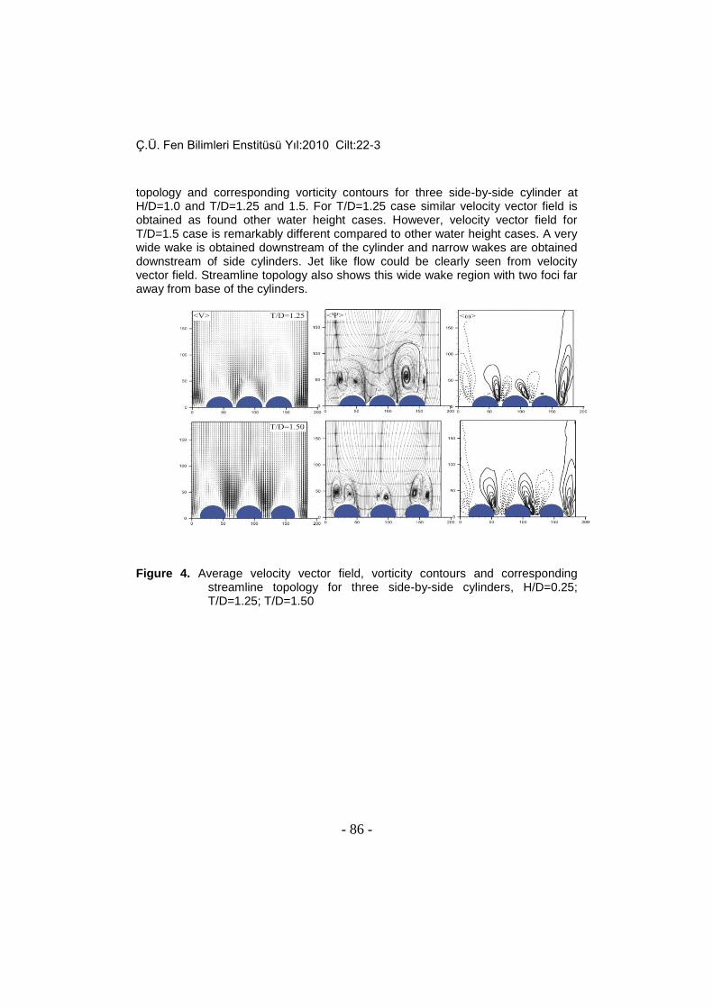
Figure 4. shows the time-averaged velocity vector field, streamline
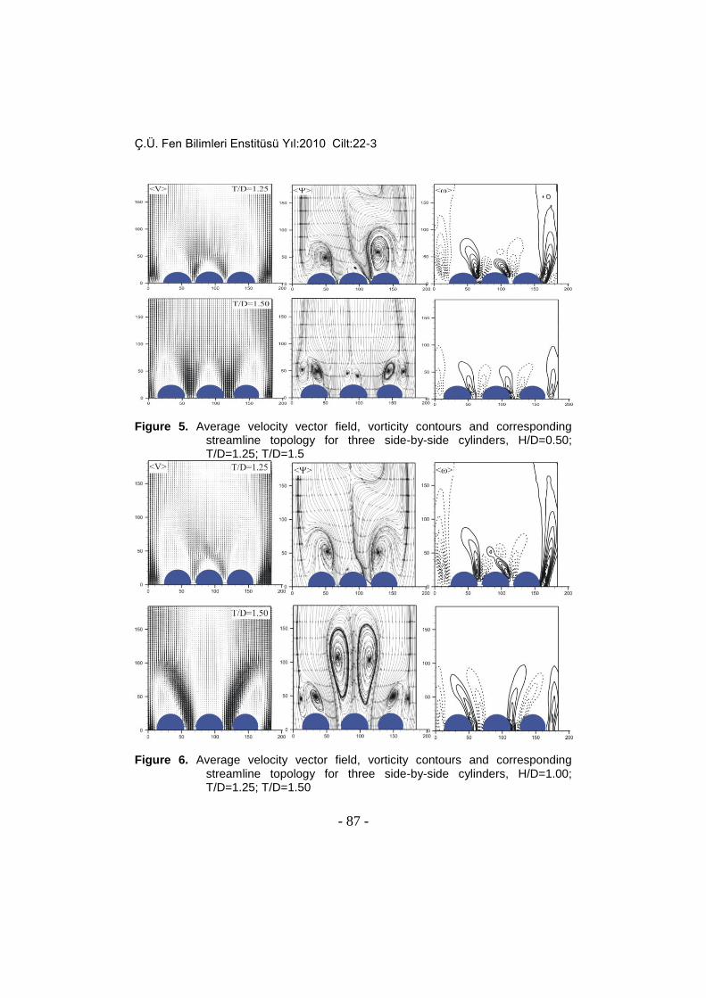
topology and corresponding vorticity contours for the case of three side-by-side circular cylinders. Here, the water height is H/D=0.25 and gap ratios are T/D=1.25 and 1.5. Similar results are obtained for both gap ratios. A narrow wake downstream of the center cylinder and two wide wakes downstream of side cylinders were obtained. Almost a symmetrical flow structure is observed. Figure 5. indicates time-averaged velocity vector field, streamline topology and corresponding vorticity contours downstream of three side-by-side cylinders for H/D=0.5 and T/D=1.25 and 1.5. Two large wake region and one very narrow wake region is evident from both velocity vector field and streamline topology for T/D=1.25 case. Streamline topology also shows unsymmetrical flow structure downstream of the cylinder. However, flow structure is symmetrical for T/D=1.5 case. The wake region of central cylinder is wider for this case compared to T/D=1.25 case. Figure 6. shows time-averaged velocity vector field, streamline
Ç.Ü. Fen Bilimleri Enstitüsü Yıl:2010 Cilt:22-3
- 86 -
topology and corresponding vorticity contours for three side-by-side cylinder at H/D=1.0 and T/D=1.25 and 1.5. For T/D=1.25 case similar velocity vector field is obtained as found other water height cases. However, velocity vector field for T/D=1.5 case is remarkably different compared to other water height cases. A very wide wake is obtained downstream of the cylinder and narrow wakes are obtained downstream of side cylinders. Jet like flow could be clearly seen from velocity vector field. Streamline topology also shows this wide wake region with two foci far away from base of the cylinders.
Figure 4. Average velocity vector field, vorticity contours and corresponding
streamline topology for three side-by-side cylinders, H/D=0.25; T/D=1.25; T/D=1.50
Ç.Ü. Fen Bilimleri Enstitüsü Yıl:2010 Cilt:22-3
- 87 -
Figure 5. Average velocity vector field, vorticity contours and corresponding
streamline topology for three side-by-side cylinders, H/D=0.50; T/D=1.25; T/D=1.5
Figure 6. Average velocity vector field, vorticity contours and corresponding
streamline topology for three side-by-side cylinders, H/D=1.00; T/D=1.25; T/D=1.50

Ç.Ü. Fen Bilimleri Enstitüsü Yıl:2010 Cilt:22-3
- 88 -
CONCLUSIONS In this study, flopping regime behind two and three side-by-side cylinders in
shallow water flow was investigated by Particle Image Velocimetry Technique. Experiments were carried out at three different water heights (10mm, 20mm and 40mm) and three different spacing (10mm, 20 mm, 30 mm) between cylinders were used. Free-stream velocity was kept constant during experiments. Namely, experiments were carried out for just one Reynolds number.
Experiments show that one wide wake region and a small wake region occur downstream of two side-by-side circular cylinders and wide wake sometimes occur downstream of left cylinder and sometimes downstream of right cylinder. This kind of flow behavior is called as flopping in literature. Both instantaneous and time-averaged velocity vector field, corresponding vorticity contours and streamline topology were obtained from PIV experiments. Time history and spectra of stream-wise velocity vector field at various locations in the flow field for different cases does not show any dominant frequency of flopping regime. Flopping regime looks completely random process of flow. However, flopping occurs in between 10 and 60 seconds time period. Moreover, this time period decreases with decreasing water height. REFERENCES CHU, H.V. and S. BABARUTSI, 1988.Confinement and bed –friction effect in
shallow turbulent mixing layers. J. Hydraulic Engineering 114: 1257-1274. CHU, H.V., WU, J.H., KHAYAT, R.E., 1991. Stability of transverse shear flows in
shallow open channels. Journal of Hydraulic Engineering, 117(10): 1370-1388.
KAHRAMAN, A., SAHIN, B., AND ROCKWELL, D., 2002. Control of vortex formation a vertical cylinder in shallow water: Effect of localized roughness elements. Experiments in Fluids, 33: 54-65.
AKILLI, H., AND ROCKWELL, D., 2002. Vortex formation from a cylinder in shallow water. Physics of Fluids, 14 (9): 2957-2967.
AKILLI, H, SAHIN, B., and TUMEN, N.F., 2005, “Suppression of vortex shedding of circular cylinder in shallow water by a splitter plate”, Flow measurement and Instrumentation, 16, pp.211-219.
SPIVACK, H.M., 1946. Vortex frequency and flow pattern in the wake of two parallel cylinders at varied spacing normal to an air stream. Journal of the Aeronautical Science, 13: 289-297.
ISHIGAI, S., NISHIKAWA, E., NISHIMURA, K., AND CHO, K., 1972. Experimental study of structures of gas flow in tube banks with tube axes normal to flow (Part I, Karman vortex flow from two tubes at various spacing). Bulletin of the JSME, 15: 949-956.
BEARMAN, P.W., AND WADCOCK, A.J., 1973. The interaction between a pair of circular cylinders normal to a stream. Journal of Fluid Mechanics, 61: 499-511.

Ç.Ü. Fen Bilimleri Enstitüsü Yıl:2010 Cilt:22-3
- 89 -
WILLIAMSON, C.H.K., 1985. Evolution of a single wake behind a pair of bluff bodies. Journal of Fluid Mechanics, 159: 1-18.
KIM, H.J., AND DURBIN, P.A., 1988. Investigation of the flow between a pair of circular cylinders in the flopping regime. Journal of Fluid Mechanics, 196: 431-448.
SUMNER, D., WANG, S.S.T., PRICE, S. J., AND PAIDOUSSIS, M.P., 1999. Fluid Behavior of side-by- side circular cylinders in steady cross-flow. Journal of Fluids and Structures 13: 309-338.
ZHOU, Y., SO, R.M.C., LIU, M.H., AND ZHANG, H.J., 2000. Complex turbulent wakes generated by two and three side-by-side cylinders. International Journal of Heat and Fluid Flow 21: 125-123.
HORI, E., 1959. Experiments on flow around a pair of parallel circular cylinders. Proceedings of the 9th Japan National congress for Applied Mechanics, Paper III-11: 231-234.
KAMEMOTO, K., 1976. Formation and interaction of two parallel vortex streets. Bulletin of the JSME, 19: 283-290.
KIYA, M., ARIE, M., TAMURA, H., AND MORI, H., 1980. Vortex shedding from two circular cylinders in staggered arrangement. Trans. ASME, Journal of Fluid Engineering, 102: 166-173.
JENDRZEJCZYK, J.A., AND CHEN, S.S., 1986. Fluid forces on two circular cylinders in cross flow. In Flow-Induced Vibration- 1986: (eds Chen, S.S., Simonis, J.C., and Shin, Y.S.,) Chicago, IL, PVP,104: 1-13.
LEGAL, P., CHAUVE, M.P., LIMA, R., AND REZENDE, J., 1990. Coupled waked behind two circular cylinder. Physical Review A, 41: 4566-4569.
SUMNER, D., WONG, S., PRICE, S.J., AND PAIDOUSSIS, M.P., 1997. Two and three side-by-side circular cylinder in steady cross-flow. Proceeding of the 16th Canadian Congress of Applied Mechanics, 1: 273-274
WEI, C.Y., AND CHANG, J.R., 1999. Study of base-bleed flow and wake downstream of two dimensional bluff bodies arranged side by side. The Sixth Military Academy Symposium on Fundamental Science, ROC.
AKILLI, H., AKAR,A. and KARAKUS, C., 2004. Flow characteristics of circular cylinders arranged side-by-side in shallow water. Flow Measurement and Instrumentation,15,187-197.