Ask A Question, Save A Life QPR For Youth ©. QPR Q uestion, P ersuade, R efer QPR For Youth ©

Single and double-acting, magnetic (QP) Double-acting magnetic, non-rotating (QPR)ø 12, 16, 20, 25, 32, 40, 50, 63, 80, 100
Short -stroke cylinders Series QP - QPR
Type of construction compact profile (QP), compact with non rotating guides (QPR)
Operation QP single and double acting, QPR double - acting
Materials aluminium body (anodized) - rolled stainless steel rod - NBR seals
Operating pressure P. min 1 bar (only double - acting) - P. max 10 bar
Operating temperature 0° ÷ 80°C (with dry air - 20°C)
Fluid clean air with or without lubrication
Standard stroke bore see table
Assembly by means of screws
T h e c o m p a n y r e s e r v e s t h e r i g h t t o v a r y m o d e l s a n d d i m e n s i o n s w i t h o u t n o t i c e .T h e s e p r o d u c t s a r e d e s i g n e d f o r i n d u s t r i a l a p p l i c a t i o n s a n d a r e n o t s u i t a b l e f o r s a l e t o t h e g e n e r a l p u b l i c .
GENERAL DATA
S E R I E SQP QPR C a t a l o g u e 2 0 0 1
1.05001
CY
LI
ND
ER
S
The Series QP and QPR short-stroke cylindersare available in 10 different bore sizes, from ø 12 to ø 100. Their compact dimensionallows the installation in small spaces. Because of their particular construction,these cylinders can be mounted by means of feet or trunnion. The guides are manufactured in the externalprofile parallel to the sliding axis on threesides. These guides are used to locate the switches that sense the piston position.
1

QP2A050A050 CY
LI
ND
ER
S
T h e c o m p a n y r e s e r v e s t h e r i g h t t o v a r y m o d e l s a n d d i m e n s i o n s w i t h o u t n o t i c e .T h e s e p r o d u c t s a r e d e s i g n e d f o r i n d u s t r i a l a p p l i c a t i o n s a n d a r e n o t s u i t a b l e f o r s a l e t o t h e g e n e r a l p u b l i c .
S E R I E SC a t a l o g u e 2 0 0 1
1
TABLE SHOWING THE OUTPUT FORCE OF SHORT-STROKE CYLINDERS SERIES QP AND QPR
ESEMPIO CODIFICA CILINDRI
SERIESQP = standardQPR = standard
antirotazione
OPERATON1 = single acting
(front spring) only QP2 = double acting3 = double acting
through rodMATERIALSA = Rolled stainless steel tube
Aluminium tube
BORE in mm
TYPE OF MOUNTINGA = standardL = cerniera maschioB = piedini
STROKE in mm
SPECIAL to be specified
ø cyl. ø rod Operating pressure in barin mm in mm Working area in cm2 1 2 3 4 5 6 7 8 9 10
Output force in N (efficiency factor = 0,9)
12 6 Thrust side 1,13 10 20 30 40 50 60 70 80 90 100Traction side 0,85 7 15 22 30 38 45 52 60 67 75
16 8 Thrust side 2,00 18 35 53 71 88 106 123 141 159 176Traction side 1,50 13 26 40 53 66 79 92 106 120 132
20 10 Thrust side 3,14 28 55 83 111 138 166 194 222 250 277Traction side 2,36 21 42 62 83 104 125 146 167 187 208
25 10 Thrust side 4,90 43 86 130 173 216 260 302 346 389 432Traction side 4,12 36 73 109 145 181 218 254 291 327 363
32 12 Thrust side 8,03 70 140 210 283 354 425 494 595 635 706Traction side 6,90 60 120 180 243 305 365 426 487 548 608
40 16 Thrust side 12,56 110 220 330 443 554 664 775 886 998 1108Traction side 10,56 93 186 280 373 465 559 652 745 838 931
50 16 Thrust side 19,62 173 346 519 692 865 1037 1210 1383 1556 1729Traction side 17,62 155 311 467 622 777 932 1088 1243 1400 1555
63 20 Thrust side 31,15 275 550 824 1098 1373 1650 1923 2198 2472 2747Traction side 28,00 247 494 740 988 1235 1480 1729 1976 2222 2470
80 25 Thrust side 50,25 443 886 1330 1772 2216 2660 3100 3545 3990 4432Traction side 45,35 400 800 1200 1600 2000 2400 2800 3200 3600 4000
100 25 Thrust side 78,50 692 1385 2077 2770 3460 4154 4847 5540 6320 6923Traction side 73,60 650 1300 1948 2608 3245 3895 4544 5193 5842 6492
TABLE SHOWING THE OUTPUT FORCE OF SINGLE-ACTING CYLINDERS SERIES QP
ø Cylinders ø 12 ø 16 ø 20 ø 25 ø 32 ø 40 ø 50 ø 63 ø 80 ø 100Strike 10 10 10 10 25 25 25 25 25 25Force of spring at rest (N) 5.2 5.2 8 9.1 9 16.2 32.4 34.3 49 85Force of compressed spring (N) 13.2 13.2 18 22 39 48.8 60 86.7 124 163
QP QPR
1.05002
Note: The brackets are supplied not mounted.

CY
LI
ND
ER
S
T h e c o m p a n y r e s e r v e s t h e r i g h t t o v a r y m o d e l s a n d d i m e n s i o n s w i t h o u t n o t i c e .T h e s e p r o d u c t s a r e d e s i g n e d f o r i n d u s t r i a l a p p l i c a t i o n s a n d a r e n o t s u i t a b l e f o r s a l e t o t h e g e n e r a l p u b l i c .
S E R I E S C a t a l o g u e 2 0 0 1
1.05003
1
Cylinders strokes in stockSerie ø 5 10 15 20 25 30 35 40 50 75 100QP 12 ■ ■ ● ■ ■ ● ■ ✖ ● ● ■
QP 16 ■ ■ ✖ ● ■ ● ■ ● ■ ✖ ● ■ ■ ■
QP 20 ■ ■ ✖ ● ■ ● ■ ● ■ ● ■ ● ■ ■ ■
QP 25 ■ ■ ✖ ● ■ ● ■ ● ■ ● ■ ● ■ ■ ● ■ ● ■
QP 32 ■ ■ ● ■ ● ■ ● ■ ✖ ● ■ ● ■ ● ■ ● ■ ● ■
QP 40 ■ ■ ● ■ ● ■ ● ■ ✖ ● ■ ■ ■ ● ■ ● ■
QP 50 ■ ● ■ ● ■ ● ■ ✖ ● ■ ● ■ ● ■ ● ■ ● ■ ●
QP 63 ■ ■ ● ■ ■ ● ■ ✖ ● ■ ■ ■ ● ■
QP 80 ■ ● ■ ● ■ ■ ✖ ● ■ ■ ■ ● ■ ●
QP 100 ■ ■ ■ ■ ■ ✖ ■ ■ ■ ● ■ ●
TABLE SHOWING THE STANDARD STROKES FOR SERIES QP CYLINDERS
MAX DEFLECTION FORCE ACCORDING TO STROKE TRANSVERSAL LOAD ACCORDING TO STROKE
x = distance from useful load baricenter
S = baricenterof useful load
F = transversal force
ø 12-16-20
ø 25-32-40
ø 50-63-80-100
X=0 mm ø 12-16-20
X=0 mm ø 25-32-40
X=0 mm ø50-63-80-100
QP QPR
■ Double-acting ✖ Single-acting ● Non-rotating
■
■
■
■ ●
■
■

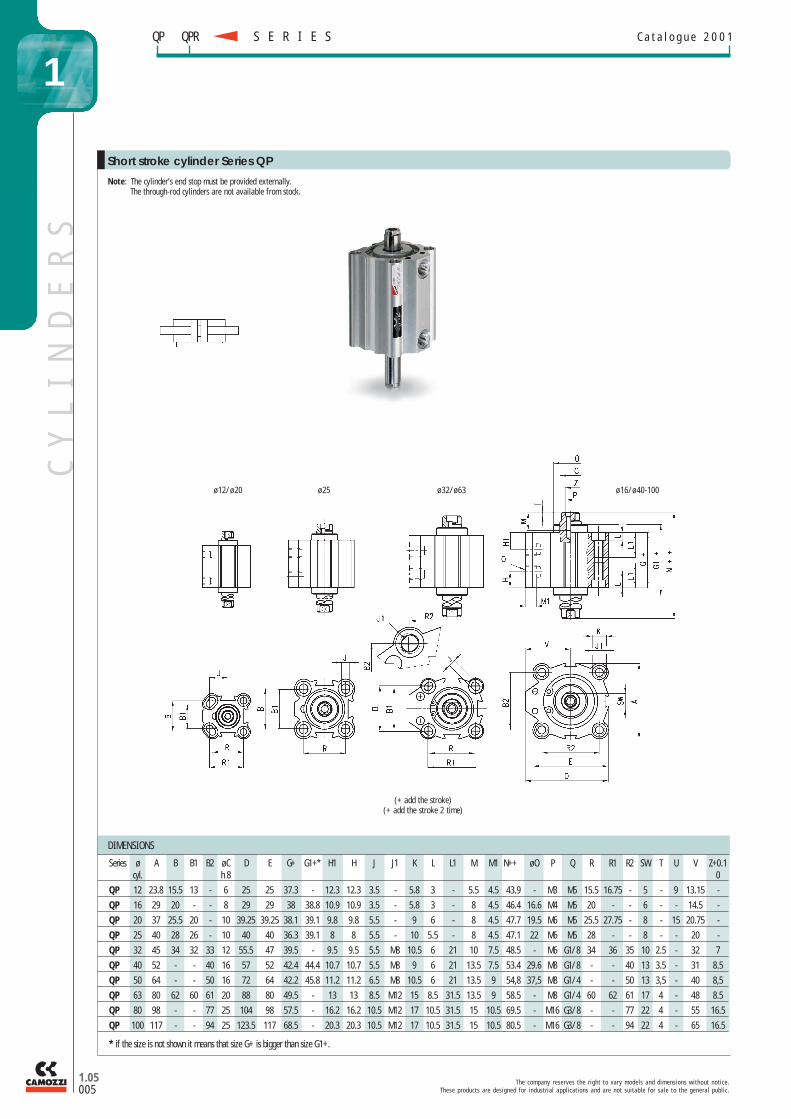
ø 12/ø 20 ø 25 ø 32/ø 63 ø 16/ø 40-100
DIMENSIONS
Series ø A B B1 B2 øC D E G+ G1+* H1 H J J1 K L L1 M M1cyl. h 8
QP 12 23.8 15.5 13 - 6 25 25 29.6 - 12.3 7.8 3.5 - 5.8 3 - 5.5 4.5
QP 16 29 20 - - 8 29 29 32 32.4 10.9 8.7 3.5 - 5.8 3 - 8 4.5
QP 20 37 25.5 20 - 10 39.25 39.25 31.2 31.7 9.8 9.8 5.5 - 9 6 - 8 4.5
QP 25 40 28 26 - 10 40 40 32.1 33.5 8 6.9 5.5 - 10 5.5 - 8 4.5
QP 32 45 34 32 33 12 55.5 47 39.5 - 9.5 9.5 5.5 M8 10.5 6 21 10 7.5
QP 40 52 - - 40 16 57 52 42.4 43.4 10.7 10.7 5.5 M8 9 6 21 13.5 7.5
QP 50 64 - - 50 16 72 64 42.2 44 11.2 11.2 6.5 M8 10.5 6 21 13.5 9
QP 63 80 62 60 61 20 88 80 49.5 - 13 13 8.5 M12 15 8.5 31.5 13.5 9
QP 80 98 - - 77 25 104 98 57.5 - 16.2 16.2 10.5 M12 17 10.5 31.5 15 10.5
QP 100 117 - - 94 25 123.5 117 68.5 - 20.3 20.3 10.5 M12 17 10.5 31.5 15 10.5
* if the size is not shown it means that size G+ is bigger than size G1+.
N++ øO P Q R R1 R2 SW T U V Z+0.10
32.9 - M3 M5 15.5 16.75 - 5 - 9 13.15 - P36.4 16.6 M4 M5 20 - - 6 - - 14.5 - P36 19.5 M6 M5 25.5 27.75 - 8 - 15 20.75 - P
37.5 22 M6 M5 28 - - 8 - - 20 - P44 - M6 G1/8 34 36 35 10 2.5 - 32 7 P
47.9 29.6 M8 G1/8 - - 40 13 3.5 - 31 8.5 P48.4 37.5 M8 G1/4 - - 50 13 3.5 - 40 8.5 P54 - M8 G1/4 60 62 61 17 4 - 48 8.5 P
63.5 - M16 G3/8 - - 77 22 4 - 55 16.5 P74.5 - M16 G3/8 - - 94 22 4 - 65 16.5 P
CY
LI
ND
ER
S
T h e c o m p a n y r e s e r v e s t h e r i g h t t o v a r y m o d e l s a n d d i m e n s i o n s w i t h o u t n o t i c e .T h e s e p r o d u c t s a r e d e s i g n e d f o r i n d u s t r i a l a p p l i c a t i o n s a n d a r e n o t s u i t a b l e f o r s a l e t o t h e g e n e r a l p u b l i c .
1.05004
S E R I E SC a t a l o g u e 2 0 0 1
1QPR
Note: The cylinder’s end stop must be provided externally.For single-acting ø 12, 16, 20 and 25 add 5 mm to sizez G+, G1+ and N+
Cilindri corsa breve Serie QP
(+ add the stroke)
QP
CY
LI
ND
ER
S
T h e c o m p a n y r e s e r v e s t h e r i g h t t o v a r y m o d e l s a n d d i m e n s i o n s w i t h o u t n o t i c e .T h e s e p r o d u c t s a r e d e s i g n e d f o r i n d u s t r i a l a p p l i c a t i o n s a n d a r e n o t s u i t a b l e f o r s a l e t o t h e g e n e r a l p u b l i c .
S E R I E S C a t a l o g u e 2 0 0 1
1.05005
1
ø 12/ø 20 ø 25 ø 32/ø 63 ø 16/ø 40-100
DIMENSIONS
Series ø A B B1 B2 øC D E G+ G1+* H1 H J J1 K L L1 M M1cyl. h 8
QP 12 23.8 15.5 13 - 6 25 25 37.3 - 12.3 12.3 3.5 - 5.8 3 - 5.5 4.5
QP 16 29 20 - - 8 29 29 38 38.8 10.9 10.9 3.5 - 5.8 3 - 8 4.5
QP 20 37 25.5 20 - 10 39.25 39.25 38.1 39.1 9.8 9.8 5.5 - 9 6 - 8 4.5
QP 25 40 28 26 - 10 40 40 36.3 39.1 8 8 5.5 - 10 5.5 - 8 4.5
QP 32 45 34 32 33 12 55.5 47 39.5 - 9.5 9.5 5.5 M8 10.5 6 21 10 7.5
QP 40 52 - - 40 16 57 52 42.4 44.4 10.7 10.7 5.5 M8 9 6 21 13.5 7.5
QP 50 64 - - 50 16 72 64 42.2 45.8 11.2 11.2 6.5 M8 10.5 6 21 13.5 9
QP 63 80 62 60 61 20 88 80 49.5 - 13 13 8.5 M12 15 8.5 31.5 13.5 9
QP 80 98 - - 77 25 104 98 57.5 - 16.2 16.2 10.5 M12 17 10.5 31.5 15 10.5
QP 100 117 - - 94 25 123.5 117 68.5 - 20.3 20.3 10.5 M12 17 10.5 31.5 15 10.5
* if the size is not shown it means that size G+ is bigger than size G1+.
N++ øO P Q R R1 R2 SW T U V Z+0.10
43.9 - M3 M5 15.5 16.75 - 5 - 9 13.15 - P46.4 16.6 M4 M5 20 - - 6 - - 14.5 - P47.7 19.5 M6 M5 25.5 27.75 - 8 - 15 20.75 - P47.1 22 M6 M5 28 - - 8 - - 20 - P48.5 - M6 G1/8 34 36 35 10 2.5 - 32 7 P53.4 29.6 M8 G1/8 - - 40 13 3.5 - 31 8.5 P54,8 37,5 M8 G1/4 - - 50 13 3,5 - 40 8,5 P58.5 - M8 G1/4 60 62 61 17 4 - 48 8.5 P69.5 - M16 G3/8 - - 77 22 4 - 55 16.5 P80.5 - M16 G3/8 - - 94 22 4 - 65 16.5 P
Note: The cylinder’s end stop must be provided externally.The through-rod cylinders are not available from stock.
Short stroke cylinder Series QP
(+ add the stroke)(+ add the stroke 2 time)
QP QPR

DIMENSIONS
Series ø cyl. A B D E G+ H1 H J K L L1 N+ N1+ Q R SW V AA
QPR 12 23.8 15.5 25 25 29.6 12.3 7.8 3.5 5.8 3 - 32.9 37.9 M5 15.5 5 13.15 5
QPR 16 29 20 29 29 32 10.9 8.7 3.5 5.8 3 - 36.4 41.4 M5 20 6 14.5 5
QPR 20 37 25.5 39.25 39.25 31.2 9.8 9.8 5.5 9 6 - 36 46 M5 25.5 8 20.75 10
QPR 25 40 28 40 40 32.1 8 6.9 5.5 10 5.5 - 37.5 47.5 M5 28 8 20 10
QPR 32 45 33 55.5 47 39.5 9.5 9.5 M8 10.5 6 21 44 54 G1/8 35 10 32 10
QPR 40 52 40 57 52 42.4 10.7 10.7 M8 9 6 21 47.9 57.9 G1/8 40 13 31 10
QPR 50 64 50 72 64 42.2 11.2 11.2 M8 10.5 6 21 48.4 60.4 G1/4 50 13 40 12
QPR 63 80 61 88 80 49.5 13 13 M12 15 8.5 31.5 54 66 G1/4 61 17 48 12
QPR 80 98 77 104 98 57.5 16.2 16.2 M12 17 10.5 31.5 63.5 78.5 G3/8 77 22 55 15
QPR 100 117 94 123.5 117 68.5 20.3 20.3 M12 17 10.5 31.5 74.5 89.5 G3/8 94 22 65 15
* Cylinders with only one guide.
BB øCC øDD EE FF LL MM NN RR VV
3.5 6.2 3.2 5.8 M3 15.5 25 24 15.5 12 P3.5 6.2 3.2 6.5 M3 20 28 28 20 - P4.6 8 4.2 9 M4 25.5 38.5 36 25.5 18 P4.6 8 4.2 10 M4 27 40 40 28 - P6 9 5.5 9 M5 32 47 45 36 - P6 9 5.5 9 M5 40 52 50 40 - P
6.8 10.5 6.5 10 M6 50 65 65 50 - P8.5 14 9 15 M6 62 80 80 62 - P10 16.5 11 17 M8 77 100 100 77 - P10 16.5 11 17 M8 94 115 115 94 - P
CY
LI
ND
ER
S
T h e c o m p a n y r e s e r v e s t h e r i g h t t o v a r y m o d e l s a n d d i m e n s i o n s w i t h o u t n o t i c e .T h e s e p r o d u c t s a r e d e s i g n e d f o r i n d u s t r i a l a p p l i c a t i o n s a n d a r e n o t s u i t a b l e f o r s a l e t o t h e g e n e r a l p u b l i c .
1.05006
S E R I E SC a t a l o g u e 2 0 0 1
1
ø 12/ø 20 ø 16/ø 25/ø 32-100
Note: The cylinder’s end stop must be provided externally.
Short stroke cylinder Series QPR
(+ add the stroke)
QP QPR
*
*

DIMENSIONS
Series øcyl. A B D E G+ H1 H J K L L1 N++ N1++ Q R SW V AA
QPR 12 23.8 15.5 25 25 37.3 12.3 12.3 3.5 5.8 3 - 43.9 48.9 M5 15.5 5 13.15 5
QPR 16 29 20 29 29 38 10.9 10.9 3.5 5.8 3 - 46.4 51.4 M5 20 6 14.5 5
QPR 20 37 25.5 39.25 39.25 38.1 9.8 9.8 5.5 9 6 - 47.7 57.5 M5 25.5 8 20.75 10
QPR 25 40 28 40 40 36.3 8 8 5.5 10 5.5 - 47.1 57.1 M5 28 8 20 10
QPR 32 45 33 55.5 47 39.5 9.5 9.5 M8 10.5 6 21 48.5 58.5 G1/8 35 10 32 10
QPR 40 52 40 57 52 42.4 10.7 10.7 M8 9 6 21 53.4 63.4 G1/8 40 13 31 10
QPR 50 64 50 72 64 42.2 11.2 11.2 M8 10.5 6 21 54.8 66.8 G1/4 50 13 40 12
QPR 63 80 61 88 80 49.5 13 13 M12 15 8.5 31.5 58.5 70.5 G1/4 61 17 48 12
QPR 80 98 77 104 98 57.5 16.2 16.2 M12 17 10.5 31.5 69.5 84.5 G3/8 77 22 55 15
QPR 100 117 94 123.5 117 68.5 20.3 20.3 M12 17 10.5 31.5 80.5 95.5 G3/8 94 22 65 15
* Cylinders with only one guide.
BB øCC øDD EE FF LL MM NN RR VV
3.5 6.2 3.2 5.8 M3 15.5 25 24 15.5 12 P3.5 6.2 3.2 6.5 M3 20 28 28 20 - P4.6 8 4.2 9 M4 25.5 38.5 36 25.5 18 P4.6 8 4.2 10 M4 27 40 40 28 - P6 9 5.5 9 M5 32 47 45 36 - P6 9 5.5 9 M5 40 52 50 40 - P
6.8 10.5 6.5 10 M6 50 65 65 50 - P8.5 14 9 15 M6 62 80 80 62 - P10 16.5 11 17 M8 77 100 100 77 - P10 16.5 11 17 M8 94 115 115 94 - P
CY
LI
ND
ER
S
T h e c o m p a n y r e s e r v e s t h e r i g h t t o v a r y m o d e l s a n d d i m e n s i o n s w i t h o u t n o t i c e .T h e s e p r o d u c t s a r e d e s i g n e d f o r i n d u s t r i a l a p p l i c a t i o n s a n d a r e n o t s u i t a b l e f o r s a l e t o t h e g e n e r a l p u b l i c .
S E R I E S C a t a l o g u e 2 0 0 1
1.05007
1QP QPR
ø 12/ø 20 ø 16/ø 25/ø 32-100
Note: The cylinder’s end stop must be provided externally.
Short stroke cylinder Series QPR
(+ add the stroke)
*
*

CY
LI
ND
ER
S
T h e c o m p a n y r e s e r v e s t h e r i g h t t o v a r y m o d e l s a n d d i m e n s i o n s w i t h o u t n o t i c e .T h e s e p r o d u c t s a r e d e s i g n e d f o r i n d u s t r i a l a p p l i c a t i o n s a n d a r e n o t s u i t a b l e f o r s a l e t o t h e g e n e r a l p u b l i c .
1.05008
S E R I E SC a t a l o g u e 2 0 0 1
1QP QPR
DIMENSIONS
Mod. øcyl. C SA XA SB XB TR G AB AH AOB - QP - 32 32 3 61.9 55.2 23.1 35.8 57 71 6.6 30 8.8B - QP - 40 40 3 64.8 59.1 26 39.7 64 78 6.6 33 8.8B - QP - 50 50 4 71.6 63.1 20.8 37.7 79 95 9 39 10.3B - QP - 63 63 4 81.9 70.2 25.1 41.8 95 113 11 46 13.8B - QP - 80 80 6 96.5 83 28.5 49 118 140 13 59 10.5B - QP -100 100 6 114.5 97.5 22.5 51.5 137 162 13 71 17
DIMENSIONS
Mod. øcyl. DC H 9 MR L C XD F G EWL - QP - 32 32 10 9 12 22 66 33 35 26L - QP - 40 40 12 13 15 25 73 40 40 28L - QP - 50 50 12 13 15 27 75.5 50 50 32L - QP - 63 63 16 15 20 32 86 61 61 40L - QP - 80 80 16 15 24 36 99.5 77 77 50L - QP -100 100 20 18 29 41 115.5 94 94 60
Feet bracket Mod. B...
Male trunnion bracket Mod. L ...
(+ add the stroke)
(+ add the stroke)